KR20200087676A - Combination valve - Google Patents
Combination valve Download PDFInfo
- Publication number
- KR20200087676A KR20200087676A KR1020190173038A KR20190173038A KR20200087676A KR 20200087676 A KR20200087676 A KR 20200087676A KR 1020190173038 A KR1020190173038 A KR 1020190173038A KR 20190173038 A KR20190173038 A KR 20190173038A KR 20200087676 A KR20200087676 A KR 20200087676A
- Authority
- KR
- South Korea
- Prior art keywords
- valve
- piston
- valve seat
- stem
- piston rod
- Prior art date
Links
- 239000002131 composite material Substances 0.000 claims description 81
- 239000012530 fluid Substances 0.000 description 7
- 230000007257 malfunction Effects 0.000 description 5
- 230000007423 decrease Effects 0.000 description 3
- 238000003780 insertion Methods 0.000 description 2
- 230000037431 insertion Effects 0.000 description 2
- 239000000203 mixture Substances 0.000 description 2
- 238000000926 separation method Methods 0.000 description 2
- 230000007704 transition Effects 0.000 description 2
- 229920000742 Cotton Polymers 0.000 description 1
- OAICVXFJPJFONN-UHFFFAOYSA-N Phosphorus Chemical compound [P] OAICVXFJPJFONN-UHFFFAOYSA-N 0.000 description 1
- 230000004308 accommodation Effects 0.000 description 1
- 238000007599 discharging Methods 0.000 description 1
- 238000004519 manufacturing process Methods 0.000 description 1
- 230000000149 penetrating effect Effects 0.000 description 1
- 230000002093 peripheral effect Effects 0.000 description 1
- 229910052698 phosphorus Inorganic materials 0.000 description 1
- 239000011574 phosphorus Substances 0.000 description 1
- 239000004065 semiconductor Substances 0.000 description 1
Images


Classifications
-
- F—MECHANICAL ENGINEERING; LIGHTING; HEATING; WEAPONS; BLASTING
- F16—ENGINEERING ELEMENTS AND UNITS; GENERAL MEASURES FOR PRODUCING AND MAINTAINING EFFECTIVE FUNCTIONING OF MACHINES OR INSTALLATIONS; THERMAL INSULATION IN GENERAL
- F16K—VALVES; TAPS; COCKS; ACTUATING-FLOATS; DEVICES FOR VENTING OR AERATING
- F16K31/00—Actuating devices; Operating means; Releasing devices
- F16K31/12—Actuating devices; Operating means; Releasing devices actuated by fluid
- F16K31/122—Actuating devices; Operating means; Releasing devices actuated by fluid the fluid acting on a piston
- F16K31/1221—Actuating devices; Operating means; Releasing devices actuated by fluid the fluid acting on a piston one side of the piston being spring-loaded
-
- F—MECHANICAL ENGINEERING; LIGHTING; HEATING; WEAPONS; BLASTING
- F16—ENGINEERING ELEMENTS AND UNITS; GENERAL MEASURES FOR PRODUCING AND MAINTAINING EFFECTIVE FUNCTIONING OF MACHINES OR INSTALLATIONS; THERMAL INSULATION IN GENERAL
- F16K—VALVES; TAPS; COCKS; ACTUATING-FLOATS; DEVICES FOR VENTING OR AERATING
- F16K15/00—Check valves
- F16K15/02—Check valves with guided rigid valve members
- F16K15/06—Check valves with guided rigid valve members with guided stems
- F16K15/063—Check valves with guided rigid valve members with guided stems the valve being loaded by a spring
-
- F16K15/186—
-
- F—MECHANICAL ENGINEERING; LIGHTING; HEATING; WEAPONS; BLASTING
- F16—ENGINEERING ELEMENTS AND UNITS; GENERAL MEASURES FOR PRODUCING AND MAINTAINING EFFECTIVE FUNCTIONING OF MACHINES OR INSTALLATIONS; THERMAL INSULATION IN GENERAL
- F16K—VALVES; TAPS; COCKS; ACTUATING-FLOATS; DEVICES FOR VENTING OR AERATING
- F16K17/00—Safety valves; Equalising valves, e.g. pressure relief valves
- F16K17/02—Safety valves; Equalising valves, e.g. pressure relief valves opening on surplus pressure on one side; closing on insufficient pressure on one side
- F16K17/04—Safety valves; Equalising valves, e.g. pressure relief valves opening on surplus pressure on one side; closing on insufficient pressure on one side spring-loaded
-
- F—MECHANICAL ENGINEERING; LIGHTING; HEATING; WEAPONS; BLASTING
- F16—ENGINEERING ELEMENTS AND UNITS; GENERAL MEASURES FOR PRODUCING AND MAINTAINING EFFECTIVE FUNCTIONING OF MACHINES OR INSTALLATIONS; THERMAL INSULATION IN GENERAL
- F16K—VALVES; TAPS; COCKS; ACTUATING-FLOATS; DEVICES FOR VENTING OR AERATING
- F16K31/00—Actuating devices; Operating means; Releasing devices
- F16K31/12—Actuating devices; Operating means; Releasing devices actuated by fluid
- F16K31/122—Actuating devices; Operating means; Releasing devices actuated by fluid the fluid acting on a piston
- F16K31/1225—Actuating devices; Operating means; Releasing devices actuated by fluid the fluid acting on a piston with a plurality of pistons
-
- F—MECHANICAL ENGINEERING; LIGHTING; HEATING; WEAPONS; BLASTING
- F16—ENGINEERING ELEMENTS AND UNITS; GENERAL MEASURES FOR PRODUCING AND MAINTAINING EFFECTIVE FUNCTIONING OF MACHINES OR INSTALLATIONS; THERMAL INSULATION IN GENERAL
- F16K—VALVES; TAPS; COCKS; ACTUATING-FLOATS; DEVICES FOR VENTING OR AERATING
- F16K31/00—Actuating devices; Operating means; Releasing devices
- F16K31/12—Actuating devices; Operating means; Releasing devices actuated by fluid
- F16K31/14—Actuating devices; Operating means; Releasing devices actuated by fluid for mounting on, or in combination with, hand-actuated valves
- F16K31/143—Actuating devices; Operating means; Releasing devices actuated by fluid for mounting on, or in combination with, hand-actuated valves the fluid acting on a piston
-
- F—MECHANICAL ENGINEERING; LIGHTING; HEATING; WEAPONS; BLASTING
- F16—ENGINEERING ELEMENTS AND UNITS; GENERAL MEASURES FOR PRODUCING AND MAINTAINING EFFECTIVE FUNCTIONING OF MACHINES OR INSTALLATIONS; THERMAL INSULATION IN GENERAL
- F16K—VALVES; TAPS; COCKS; ACTUATING-FLOATS; DEVICES FOR VENTING OR AERATING
- F16K31/00—Actuating devices; Operating means; Releasing devices
- F16K31/44—Mechanical actuating means
- F16K31/50—Mechanical actuating means with screw-spindle or internally threaded actuating means
-
- F—MECHANICAL ENGINEERING; LIGHTING; HEATING; WEAPONS; BLASTING
- F16—ENGINEERING ELEMENTS AND UNITS; GENERAL MEASURES FOR PRODUCING AND MAINTAINING EFFECTIVE FUNCTIONING OF MACHINES OR INSTALLATIONS; THERMAL INSULATION IN GENERAL
- F16K—VALVES; TAPS; COCKS; ACTUATING-FLOATS; DEVICES FOR VENTING OR AERATING
- F16K31/00—Actuating devices; Operating means; Releasing devices
- F16K31/44—Mechanical actuating means
- F16K31/60—Handles
-
- F—MECHANICAL ENGINEERING; LIGHTING; HEATING; WEAPONS; BLASTING
- F16—ENGINEERING ELEMENTS AND UNITS; GENERAL MEASURES FOR PRODUCING AND MAINTAINING EFFECTIVE FUNCTIONING OF MACHINES OR INSTALLATIONS; THERMAL INSULATION IN GENERAL
- F16K—VALVES; TAPS; COCKS; ACTUATING-FLOATS; DEVICES FOR VENTING OR AERATING
- F16K7/00—Diaphragm valves or cut-off apparatus, e.g. with a member deformed, but not moved bodily, to close the passage ; Pinch valves
- F16K7/12—Diaphragm valves or cut-off apparatus, e.g. with a member deformed, but not moved bodily, to close the passage ; Pinch valves with flat, dished, or bowl-shaped diaphragm
- F16K7/14—Diaphragm valves or cut-off apparatus, e.g. with a member deformed, but not moved bodily, to close the passage ; Pinch valves with flat, dished, or bowl-shaped diaphragm arranged to be deformed against a flat seat
- F16K7/16—Diaphragm valves or cut-off apparatus, e.g. with a member deformed, but not moved bodily, to close the passage ; Pinch valves with flat, dished, or bowl-shaped diaphragm arranged to be deformed against a flat seat the diaphragm being mechanically actuated, e.g. by screw-spindle or cam
-
- F—MECHANICAL ENGINEERING; LIGHTING; HEATING; WEAPONS; BLASTING
- F16—ENGINEERING ELEMENTS AND UNITS; GENERAL MEASURES FOR PRODUCING AND MAINTAINING EFFECTIVE FUNCTIONING OF MACHINES OR INSTALLATIONS; THERMAL INSULATION IN GENERAL
- F16K—VALVES; TAPS; COCKS; ACTUATING-FLOATS; DEVICES FOR VENTING OR AERATING
- F16K7/00—Diaphragm valves or cut-off apparatus, e.g. with a member deformed, but not moved bodily, to close the passage ; Pinch valves
- F16K7/12—Diaphragm valves or cut-off apparatus, e.g. with a member deformed, but not moved bodily, to close the passage ; Pinch valves with flat, dished, or bowl-shaped diaphragm
- F16K7/14—Diaphragm valves or cut-off apparatus, e.g. with a member deformed, but not moved bodily, to close the passage ; Pinch valves with flat, dished, or bowl-shaped diaphragm arranged to be deformed against a flat seat
- F16K7/17—Diaphragm valves or cut-off apparatus, e.g. with a member deformed, but not moved bodily, to close the passage ; Pinch valves with flat, dished, or bowl-shaped diaphragm arranged to be deformed against a flat seat the diaphragm being actuated by fluid pressure
Abstract
Description
본 발명은, 파일럿밸브기구와 수동기구를 일체화한 복합밸브에 관한 것이다.The present invention relates to a composite valve in which a pilot valve mechanism and a manual mechanism are integrated.
예를 들어, 반도체 제조장치와 같은 가스설비에서는, 파일럿밸브가 가스배관에 배설되어, 가스의 제어를 행하고 있다. 파일럿밸브는, 예를 들어 가스배관을 교환하는 작업 중에 오동작에 의해 가스누설을 발생시키는 것을 방지하기 위해, 안전장치가 필요시된다. 한편, 가스설비를 컴팩트하게 하기 위해, 가스설비를 구성하는 장치에는 소형화가 요구되고 있다. 이에, 종래, 파일럿밸브기구와, 파일럿밸브기구의 오동작을 방지하는 안전장치로서 동작하는 수동기구를 일체화한 복합밸브가, 가스설비에 이용되고 있다(예를 들어, 특허문헌 1, 특허문헌 2, 특허문헌 3, 특허문헌 4 참조).For example, in a gas facility such as a semiconductor manufacturing apparatus, a pilot valve is disposed in a gas pipe to control gas. The pilot valve requires a safety device, for example, in order to prevent gas leakage due to malfunction during operation of replacing the gas pipe. On the other hand, in order to make the gas facility compact, the apparatus constituting the gas facility is required to be miniaturized. Thus, conventionally, a composite valve in which a pilot valve mechanism and a manual mechanism that functions as a safety device for preventing malfunction of the pilot valve mechanism are integrated is used in gas equipment (for example,
예를 들어 특허문헌 1에 기재되는 복합밸브에서는, 부세부재에 의해 밸브시트방향으로 부세되고 있는 피스톤이 공기압에 의해 반밸브시트방향으로 가압되고, 밸브체와 밸브시트를 이간시키고 있는 경우에, 핸들이 회전되면, 핸들에 결합된 수동스템이, 나사부에 의해 밸브시트방향으로 이동하고, 서브로드에 당접한다. 서브로드는, 수동스템의 밸브시트방향으로의 이동에 따라, 피스톤에 일체적으로 부착된 피스톤로드를 압하하고, 밸브체를 밸브시트에 당접시킨다. 이 상태에 있어서, 피스톤로드가 수동스템에 의해 반밸브시트방향으로 이동하는 것이 제한되어 있으므로, 복합밸브는, 공기압의 공급에 상관없이, 밸브체와 밸브시트가 당접되어 있는 상태가 유지된다.For example, in the composite valve described in
예를 들어, 특허문헌 2, 특허문헌 3, 특허문헌 4에 기재되는 복합밸브에서는, 파일럿기구의 가압실에 조작에어를 공급하여 밸브체와 밸브시트를 이간시키고 있는 경우에, 핸들을 조작하면, 가압실의 조작에어가 배출된다. 가압실의 내압이 저하되면, 조작에어에 의해 가압되어 있던 피스톤이 스프링의 부세력에 의해 밸브시트방향으로 이동하고, 피스톤로드를 개재하여 밸브체를 밸브시트에 당접시킨다. 핸들이 회전되면, 핸들에 결합된 수동스템이 밸브시트방향으로 이동하여 피스톤로드의 이동을 제한하고, 조작에어의 공급에 상관없이, 밸브체와 밸브시트가 당접되어 있는 상태를 유지한다.For example, in the composite valve described in
그러나, 상기 종래기술에는, 이하의 문제가 있었다. 즉, 특허문헌 1에 기재되는 복합밸브에서는, 밸브체가 밸브시트로부터 이간되어 있는 상태에서 핸들을 회전시키는 경우, 피스톤에 작용하는 반밸브시트방향의 공기압이, 피스톤로드를 개재하여 나사부에 작용한다. 이 때문에, 특허문헌 1에 기재되는 복합밸브의 핸들은, 공기압에 저항하여 회전시켜야 하므로, 핸들을 돌릴 때에 큰 힘이 필요했다.However, the prior art has the following problems. That is, in the composite valve described in
특허문헌 2, 특허문헌 3, 특허문헌 4에 기재되는 복합밸브에서는, 핸들을 회전시킬 때에, 가압실의 조작에어를 배출하여 가압실의 내압을 저하시키고 있으므로, 특허문헌 1에 기재되는 복합밸브보다 작은 힘으로 핸들을 돌릴 수 있다. 그러나, 핸들의 조작에 따라 가압실의 조작에어를 배출하기 위한 유로나 부재가 필요해지고, 복합밸브의 구조가 복잡해졌다.In the composite valves described in
본 발명은, 상기 문제점을 해결하기 위하여 이루어진 것으로, 밸브체와 밸브시트가 이간되어 있는 경우에 핸들을 회전시키는 힘을, 간단한 구조로, 작게 할 수 있는 복합밸브를 제공하는 것을 목적으로 한다.The present invention has been made to solve the above problems, and an object of the present invention is to provide a composite valve capable of reducing the force of rotating the handle when the valve body and the valve seat are separated with a simple structure.
본 발명의 일태양은, 다음과 같은 구성을 갖고 있다. (1) 밸브시트와, 밸브체와, 공기압을 이용하여 상기 밸브체를 상기 밸브시트에 자동적으로 당접 또는 이간시키는 파일럿기구와, 상기 밸브체와 상기 밸브시트가 당접되어 있는 상태를 상기 공기압의 공급에 상관없이 유지하는 수동기구를 구비하는 복합밸브에 있어서, 상기 파일럿기구는, 피스톤과, 상기 피스톤을 밸브시트방향으로 부세하는 제1 부세부재와, 상기 피스톤에 슬라이드이동가능하게 관통되고, 상기 제1 부세부재의 부세력을 상기 피스톤으로부터 전달받아 상기 밸브체를 상기 밸브시트에 당접시키는 피스톤로드를 갖는 것, 상기 수동기구는, 상기 피스톤로드와 동축 상에 배치된 수동스템과, 상기 수동스템에 결합되는 핸들과, 상기 핸들의 회전에 따라 상기 수동스템을 축선방향으로 이동시키는 나사부를 갖는 것, 상기 피스톤로드는, 상기 밸브체와 상기 밸브시트가 이간되어 있는 상태에서 상기 수동스템을 밸브시트방향으로 이동시키도록 상기 핸들이 회전된 경우, 상기 피스톤에 대하여 상대적으로 밸브시트방향으로 이동하도록 배치되어 있는 것을 특징으로 한다.One aspect of the present invention has the following configuration. (1) Supply of the air pressure to a valve seat, a valve body, a pilot mechanism for automatically contacting or separating the valve body from the valve seat using air pressure, and a state in which the valve body and the valve seat are in contact with each other. In the composite valve having a manual mechanism for maintaining regardless of the pilot mechanism, the pilot mechanism, the piston, the first biasing member for biasing the piston in the valve seat direction, and the slide through the piston slidably, the said 1 having a piston rod receiving the biasing force of the biasing member from the piston to abut the valve body to the valve seat, the manual mechanism comprising: a manual stem disposed coaxially with the piston rod, and the manual stem Having a handle to be coupled, and a screw portion for moving the manual stem in the axial direction according to the rotation of the handle, the piston rod, the valve body and the valve seat in the state that the valve seat is spaced apart from the manual stem When the handle is rotated to move to, it is characterized in that it is arranged to move in the valve seat direction relative to the piston.
상기 구성의 복합밸브에 있어서는, 밸브체가 밸브시트로부터 이간되어 있는 경우에, 핸들을 회전시켜, 피스톤로드를 밸브시트방향으로 이동시킬 때, 공기압이 반밸브시트방향으로 작용하고 있는 피스톤으로부터 피스톤로드가 분리되므로, 피스톤에 작용하고 있는 공기압이 피스톤로드를 개재하여 나사부에 작용하지 않는다. 따라서, 상기 구성의 복합밸브는, 피스톤로드가 피스톤에 일체적으로 마련되고, 피스톤에 작용하고 있는 공기압이 피스톤로드를 개재하여 나사부에 작용하는 종래의 복합밸브(예를 들어 특허문헌 1 참조)보다, 핸들을 돌리는 힘이 작아진다. 또한, 상기 구성의 복합밸브는, 피스톤에 작용하는 공기압을 저하시키기 위한 유로나 부재를 필요로 하지 않으므로, 구조가 간단하다. 따라서, 상기 구성의 복합밸브에 따르면, 밸브체와 밸브시트가 이간되어 있는 경우에 핸들을 회전시키는 힘을, 간단한 구조로, 작게 할 수 있다.In the composite valve of the above configuration, when the valve body is separated from the valve seat, when the piston rod is moved by moving the handle to move the piston rod in the valve seat direction, the piston rod from the piston acting in the anti-valve seat direction Since it is separated, the air pressure acting on the piston does not act on the screw portion via the piston rod. Therefore, in the composite valve of the above configuration, the piston rod is integrally provided with the piston, and the air pressure acting on the piston is applied to the threaded portion via the piston rod (for example, see Patent Document 1). , The power to turn the handle becomes smaller. In addition, the composite valve of the above configuration is simple in structure because it does not require a flow path or member for reducing the air pressure acting on the piston. Therefore, according to the composite valve of the above configuration, when the valve body and the valve seat are separated, the force for rotating the handle can be reduced with a simple structure.
(2) (1)에 기재된 복합밸브에 있어서, 상기 피스톤로드는, 상기 피스톤의 밸브시트측에 위치하는 면에 당접 또는 이간하는 것이 가능한 당접부를 갖는 것, 상기 제1 부세부재보다 부세력이 작고, 상기 피스톤로드를 반밸브시트방향으로 부세하는 제2 부세부재를 갖는 것이 바람직하다.(2) In the composite valve according to (1), the piston rod has a contact portion capable of being abutted or separated from a surface located on the valve seat side of the piston, and has less force than the first biasing member. , It is preferable to have a second biasing member for biasing the piston rod in the anti-valve seat direction.
상기 구성의 복합밸브에 따르면, 파일럿기구를 이용하여 밸브체와 밸브시트를 당접 또는 이간시키는 경우에, 피스톤로드가 피스톤에 추종하여 이동하므로, 유체를 응답성 좋게 제어할 수 있다. 또한, 상기 구성의 복합밸브에 따르면, 제2 부세부재의 부세력이 제1 부세부재의 부세력보다 작으므로, 밸브체와 밸브시트가 이간되어 있는 경우에 핸들을 회전시키는 힘을 작게 할 수 있다.According to the composite valve of the above configuration, when the valve body and the valve seat are contacted or separated using a pilot mechanism, the piston rod moves following the piston, so that the fluid can be controlled responsively. Further, according to the composite valve of the above configuration, since the biasing force of the second biasing member is smaller than the biasing force of the first biasing member, it is possible to reduce the force of rotating the handle when the valve body and the valve seat are separated. .
(3) (2)에 기재된 복합밸브에 있어서, 상기 피스톤은, 반밸브시트방향으로 돌상(突狀)으로 마련된 오목부를 갖는 것, 상기 제2 부세부재는, 상기 오목부의 내측에 배치되어 있는 것이 바람직하다.(3) In the composite valve according to (2), the piston has a concave portion provided in a protruding direction in the half-valve seat direction, and the second biasing member is disposed inside the concave portion. desirable.
상기 구성의 복합밸브에 따르면, 제2 부세부재를 컴팩트하게 배치하여, 밸브사이즈를 제어할 수 있다.According to the composite valve of the above configuration, the second biasing member can be compactly arranged to control the valve size.
(4) (1) 내지 (3) 중 어느 하나에 기재된 복합밸브에 있어서, 상기 수동스템은, 핸들과 일체적으로 회전동작만 행하도록 배치된 제1 스템과, 상기 나사부의 나사이송에 의해 축선방향으로 이동하는 제2 스템과, 상기 제1 스템을 상기 제2 스템에 계합시키는 계합부를 갖는 것, 상기 계합부에 여유가 마련되어 있는 것이 바람직하다.(4) In the composite valve according to any one of (1) to (3), the manual stem comprises a first stem arranged to perform only a rotational operation integrally with a handle, and an axis line by screwing the screw portion. It is preferable to have a second stem moving in the direction, an engaging portion for engaging the first stem with the second stem, and a margin provided in the engaging portion.
상기 구성의 복합밸브에 따르면, 핸들의 조작에 여유를 마련하여, 오작동을 방지할 수 있다.According to the composite valve of the above configuration, it is possible to provide a margin for the operation of the handle and prevent malfunction.
본 발명에 따르면, 간단한 구조로, 밸브체와 밸브시트가 이간되어 있는 경우에 핸들을 회전시키는 힘을 작게 할 수 있는 복합밸브를 제공할 수 있다.According to the present invention, a simple structure, it is possible to provide a composite valve capable of reducing the force of rotating the handle when the valve body and the valve seat are separated.
도 1은 본 발명의 실시형태에 따른 복합밸브의 단면도로서, 수동기구가 안전기구 해제상태, 파일럿기구가 자동폐쇄상태, 밸브기구가 밸브폐쇄상태인 복합밸브를 나타낸다.
도 2는 도 1에 나타내는 복합밸브의 평면도이다.
도 3은 도 1의 A부 확대도이다.
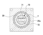
도 4는 도 1의 B-B단면도이다.
도 5는 복합밸브의 단면도로서, 수동기구가 안전기구 해제상태, 파일럿기구가 자동개방상태, 밸브기구가 밸브개방상태인 복합밸브를 나타낸다.
도 6은 복합밸브의 단면도로서, 수동기구가 안전기구 세트상태, 파일럿기구가 자동개방상태, 밸브기구가 밸브폐쇄상태인 복합밸브를 나타낸다.
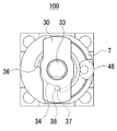
도 7은 도 6에 나타내는 복합밸브의 평면도이다.
도 8은 복합밸브의 단면도로서, 수동기구가 안전기구 세트상태, 파일럿기구가 자동폐쇄상태, 밸브기구가 밸브폐쇄상태인 복합밸브를 나타낸다.1 is a cross-sectional view of a composite valve according to an embodiment of the present invention, showing a composite valve in which the manual mechanism is in a safety mechanism release state, the pilot mechanism is in an automatic closing state, and the valve mechanism is in a valve closing state.
FIG. 2 is a plan view of the composite valve shown in FIG. 1.
3 is an enlarged view of part A of FIG. 1.
4 is a cross-sectional view taken along line BB of FIG. 1.
5 is a cross-sectional view of a composite valve, showing a composite valve in which the manual mechanism is in the safety mechanism release state, the pilot mechanism is in the automatic open state, and the valve mechanism is in the valve open state.
6 is a cross-sectional view of a composite valve, showing a composite valve in which the manual mechanism is a safety mechanism set state, the pilot mechanism is an automatic open state, and the valve mechanism is a valve closed state.
7 is a plan view of the composite valve shown in FIG. 6.
8 is a cross-sectional view of a composite valve, showing a composite valve in which the manual mechanism is a safety mechanism set state, the pilot mechanism is an automatic closing state, and the valve mechanism is a valve closing state.
이하에, 본 발명에 따른 복합밸브의 실시형태에 대하여 도면에 기초하여 설명한다. 도 1은, 본 발명의 실시형태에 따른 복합밸브(100)의 단면도로서, 수동기구(102)가 안전기구 해제상태, 파일럿기구(101)가 자동폐쇄상태, 밸브기구(103)가 밸브폐쇄상태인 복합밸브(100)를 나타낸다. 도 2는, 도 1에 나타내는 복합밸브(100)의 평면도이다. 도 3은, 도 1의 A부 확대도이다. 도 4는, 도 1의 B-B단면도이다. 도 5는, 복합밸브(100)의 단면도로서, 수동기구(102)가 안전기구 해제상태, 파일럿기구(101)가 자동개방상태, 밸브기구(103)가 밸브개방상태인 복합밸브(100)를 나타낸다. 도 6은, 복합밸브(100)의 단면도로서, 수동기구(102)가 안전기구 세트상태, 파일럿기구(101)가 자동개방상태, 밸브기구(103)가 밸브폐쇄상태인 복합밸브(100)를 나타낸다. 도 7은, 도 6에 나타내는 복합밸브(100)의 평면도이다. 도 8은, 복합밸브(100)의 단면도로서, 수동기구(102)가 안전기구 세트상태, 파일럿기구(101)가 자동폐쇄상태, 밸브기구(103)가 밸브폐쇄상태인 복합밸브를 나타낸다. 한편, 본 형태에 있어서, 「상방」이란 복합밸브(100)의 핸들(30)측, 「하방」이란 복합밸브(100)의 밸브본체(1)측을 가리키는 것으로 한다. 또한, 도 2에 나타내는 핸들(30)의 위치(방향)를 「자동개폐가능위치」, 도 7에 나타내는 핸들(30)의 위치(방향)를 「자동개폐불가능위치」로 한다.EMBODIMENT OF THE INVENTION Hereinafter, embodiment of the composite valve which concerns on this invention is demonstrated based on drawing. 1 is a cross-sectional view of a
(복합밸브의 전체구성)(Overall configuration of the composite valve)
도 1에 나타낸 바와 같이, 복합밸브(100)는, 밸브본체(1), 하부커버(4), 하부실린더(2), 상부실린더(3), 상부커버(7)가 일체가 되어 구성되어 있다. 복합밸브(100)는, 유체의 흐름을 제어하는 밸브기구(103)와, 공기압을 이용하여 밸브기구(103)를 자동적으로 개폐하는 파일럿기구(101)와, 밸브기구(103)의 밸브폐쇄상태를 공기압의 공급에 상관없이 유지하고, 파일럿기구(101)의 오동작을 방지하는 안전장치로서 기능하는 수동기구(102)를 구비한다.As shown in Fig. 1, the
(밸브기구의 구성)(Configuration of valve mechanism)
밸브기구(103)는, 밸브본체(1)와, 다이어프램밸브체(16)와, 밸브시트(13)와, 입력포트(11)와, 출력포트(12)를 구비한다. 밸브본체(1)는, 입력포트(11)와 출력포트(12)가 연통부(14)를 개재하여 연통하도록 형성되어 있다. 다이어프램밸브체(16)는, 밸브본체(1)와 스템유지체(5)의 사이에서 외연부가 협지되고, 밸브시트(13)에 당접 또는 이간한다. 밸브본체(1)와 하부커버(4)는, 다이어프램밸브체(16)에 의해 기밀하게 구획되고, 연통부(14)를 흐르는 유체가 하부커버(4)측으로 누설되지 않는다.The
스템(6)은, 통형상의 스템유지체(5)의 내부에 슬라이드이동가능하게 배치되어 있다. 스템(6)의 하면은, 다이어프램밸브체(16)에 당접하고 있다. 다이어프램밸브체(16)는, 스템(6)에 의해 하방(밸브시트방향)으로 부세되지 않는 경우에는 밸브시트(13)와 이간하고, 스템(6)에 의해 하방으로 부세되는 경우에는 밸브시트(13)에 당접하도록, 배치되어 있다.The
(파일럿기구의 구성)(Pilot mechanism composition)
파일럿기구(101)는, 하부실린더(2)와, 상부실린더(3)와, 상부커버(7)와, 제1 피스톤(20)과, 제2 피스톤(21)과, 피스톤로드(26)와, 제1 스프링(24b)과, 제2 스프링(24a)을 구비한다. 제1 피스톤(20)과 제2 피스톤(21)은, 「피스톤」의 일 예이다. 제1 스프링(24b)과 제2 스프링(24a)은, 「제1 부세부재」의 일 예이다. 한편, 본 형태의 파일럿기구(101)는, 피스톤을 2개 구비하나, 피스톤을 스프링과 쌍으로 1개 또는 3개 이상 구비할 수도 있다.The
하부실린더(2)와 상부실린더(3)는, 분리부(28)에 의해 기밀하게 분리되어 있다. 제1 피스톤(20)은, 상부실린더(3)에 슬라이드이동가능하게 장전되어 있다. 상부실린더(3)의 내부공간은, 제1 피스톤(20)에 의해 상하 2실로 기밀하게 분할되고, 하실이 1 가압실(22a)로 되어 있다. 제2 피스톤(21)은, 하부실린더(2)에 슬라이드이동가능하게 장전되어 있다. 하부실린더(2)의 내부공간은, 제2 피스톤(21)에 의해 상하 2실로 기밀하게 구획되고, 하실이 제2 가압실(22b)로 되어 있다.The
상부커버(7)는, 조작에어를 급배기하기 위한 조작포트(23)가 개설되고, 이음매(46)가 조작포트(23)에 장착되어 있다. 조작포트(23)는, 하부스템(29)에 형성된 연통유로(53), 피스톤로드(26)에 형성된 중앙유로(54), 제1 바이패스유로(55)를 개재하여 제1 가압실(22a)에 연통하고, 그리고, 피스톤로드(26)에 형성된 제2 바이패스유로(56)를 개재하여 제2 가압실(22b)에 연통하고 있다.In the
제1 스프링(24b)은, 제1 피스톤(20)의 상방에 축설되고, 제1 피스톤(20)을 하방으로 상시 부세하고 있다. 또한, 제2 스프링(24a)은, 제2 피스톤(21)의 상방에 축설되고, 제2 피스톤(21)을 하방으로 상시 부세하고 있다.The
피스톤로드(26)는, 제1 피스톤(20)과 제2 피스톤(21)에 상하방향으로 슬라이드이동가능하게 관통되어 있다. 피스톤로드(26)는, 제1 축받이(44b)를 개재하여 상부실린더(3)의 상부관통구멍(39)에 상하방향으로 이동가능하게 유지되고, 제2 축받이(44a)를 개재하여 하부실린더(2)의 하부관통구멍(27)에 상하방향으로 이동가능하게 유지되어 있다. 피스톤로드(26)는, O링(25b)을 개재하여 상부관통구멍(39)에 끼워져 통과(嵌揷)되고, O링(25a)을 개재하여 하부관통구멍(27)에 끼워져 통과되고 있으며, 상부실린더(3) 내와 하부실린더(2) 내를 기밀하게 슬라이드이동한다. 피스톤로드(26)는, 하단부가 밸브본체(1)측까지 연장되고, 선단부가 스템(6)의 근방에 배치된다.The
도 3에 나타낸 바와 같이, 피스톤로드(26)는, 제1 피스톤(20)의 하측(밸브시트(13)측)이 되는 위치에 단차부(262)가 마련되고, 제2 피스톤(21)의 하측이 되는 위치에 당접부(261)가 마련되어 있다. 피스톤로드(26)는, 제1 스프링(24b)으로 부세된 제1 피스톤(20)이 단차부(262)에 당접하고, 제2 스프링(24a)으로 부세된 제2 피스톤(21)이 당접부(261)에 당접하고 있으며, 제1 스프링(24b)의 탄성력과 제2 스프링(24a)의 탄성력의 합력에 의해 하방으로 부세되어 있다. 단차부(262)와 당접부(261)는, 「당접부」의 일 예이다.As shown in FIG. 3, the
피스톤로드(26)는, 당접부(261)와 하부실린더(2)의 사이에 제3 스프링(61)이 축설되고, 제3 스프링(61)의 탄성력에 의해 상방(밸브시트(13)와 반대방향인 반밸브시트방향)으로 부세되어 있다. 제3 스프링(61)의 탄성력은, 제1 스프링(24b)의 탄성력과 제2 스프링(24a)의 탄성력의 합력보다 작다. 제3 스프링(61)은, 「제2 부세부재」의 일 예이다. 이 때문에, 피스톤로드(26)는, 제1 가압실(22a)과 제2 가압실(22b)이 가압되지 않은 경우, 하방으로 이동하고, 스템(6)을 개재하여 다이어프램밸브체(16)를 밸브시트(13)에 당접시키고 있다.In the
제2 피스톤(21)은, 중앙부(211)가 상방으로 돌출된 오목형상으로 형성되고, 오목부(212)를 구비한다. 오목부(212)의 중앙에는, 중앙관통구멍(215)이 형성되어 있다. 피스톤로드(26)는, 당접부(261)를 오목부(212)가 형성된 중앙부(211)의 내벽에 당접시키도록, O링(25e)을 개재하여 중앙관통구멍(215)에 끼워져 통과되고, 제2 피스톤(21)을 기밀하게 슬라이드이동할 수 있다. 오목부(212)는, 제3 스프링(61)을 수용하는 수용공간(213)을 형성한다.The
하부실린더(2)는, 상방으로 돌출하도록 마련된 보스부(2a)를 구비하고, 보스부(2a)가 오목부(212)의 내측에 배치되어 있다. 보스부(2a)의 외경은, 오목부(212)의 내경보다 작아지도록 설정되고, 오목부(212)의 내측면과 보스부(2a)의 외주면의 사이에 공극부(214)가 환상으로 마련되어 있다. 피스톤로드(26)는, 당접부(261)보다 하측에 제2 바이패스유로(56)가 형성되어 있다. 이 때문에, 조작에어는, 제2 피스톤(21)의 상방으로 누설되지 않도록, 제2 바이패스유로(56)로부터 수용공간(213)과 공극부(214)와 제2 가압실(22b)에 충전되고, 제2 피스톤(21)을 상방으로 가압한다.The
(수동기구의 구성)(Composition of manual mechanism)
도 1에 나타낸 바와 같이, 수동기구(102)는, 수동스템(31)과, 핸들(30)과, 나사부(41)를 구비한다. 수동스템(31)은, 캠부재(33)와 상부스템(32)과 하부스템(29)에 의해 구성되어 있다. 상부스템(32)은 「제1 스템」의 일 예이며, 하부스템(29)은 「제2 스템」의 일 예이다.As shown in Fig. 1, the
상부스템(32)은, 상부커버(7)의 삽입통과구멍(48)에 삽통되고, 하부스템(29)의 상방에 배치되어 있다. 상부스템(32)은, C링(43, 42)을 개재하여 상부커버(7)에 부착되고, 회전동작만을 행하도록 삽입통과구멍(48)에 배치되어 있다.The
도 6에 나타낸 바와 같이, 캠부재(33)는, 상부커버(7)로부터 돌출하는 상부스템(32)의 상단부에, 정지나사(47)를 이용하여 고정되어 있다. 도 7에 나타낸 바와 같이, 핸들(30)은, 캠부재(33)에 대하여 회전정지된 상태로 연결되어 있다. 따라서, 상부스템(32)과 캠부재(33)와 핸들(30)은, 일체적으로 회전한다. 도 1 및 도 6에 나타낸 바와 같이, 상부스템(32)은, 계합부(70)를 개재하여 하부스템(29)에 계합되고, 핸들(30)의 회전에 따라 하부스템(29)을 회전시킨다.As shown in Fig. 6, the
도 1에 나타낸 바와 같이, 상부스템(32)은, 상부커버(7)에 형성된 바닥이 있는 구멍부(52) 내에 돌출하는 하단부에, 계합편(72)이 하방으로 돌출하도록 마련되어 있다. 하부스템(29)은, 밸브시트(13)와 반대측에 위치하는 상면에 계합홈(71)이 형성되고, 계합편(72)이 계합홈(71)에 유감(遊嵌)되어 있다. 계합편(72)과 계합홈(71)에 의해, 계합부(70)가 구성되어 있다.As shown in FIG. 1, the
예를 들어, 도 4에 나타낸 바와 같이, 계합홈(71)과 계합편(72)은 마이너스형상으로 마련되고, 상부스템(32)과 하부스템(29)이 일체적으로 회전할 수 있도록 계합된다. 계합부(70)는, 계합홈(71)의 내벽과 계합편(72)의 사이에 클리어런스가 마련되고, 상부스템(32)의 회전을 하부스템(29)에 전달하지 않는 여유의 영역을 구비한다.For example, as shown in FIG. 4, the engaging
도 1에 나타낸 바와 같이, 상부실린더(3)의 상면에는, 상부관통구멍(39)과 동축이 되도록, 개구부(40)가 형성되어 있다. 하부스템(29)은, 개구부(40)의 내부에 배치되고, 나사부(41)를 개재하여 상부실린더(3)에 상하방향으로 이동가능하게 부착되어 있다. 하부스템(29)은, 밸브시트(13)측에 위치하는 하면의 중앙부에, 스토퍼부(291)가 돌설되어 있다. 스토퍼부(291)는, 상부관통구멍(39)에 슬라이드이동가능하게 감합되고, 상부관통구멍(39)의 내부에서 피스톤로드(26)의 상부에 당접할 수 있도록 배치되어 있다.1, an
하부스템(29)에는, 연통유로(53)가 축선방향으로 관통하여 형성되어 있다. 연통유로(53)는, 상부관통구멍(39)을 개재하여, 피스톤로드(26)의 상단부에 개구하는 중앙유로(54)에 연통하고 있다. 상기 서술한 바와 같이, 계합홈(71)의 내벽과 계합편(72)의 사이에는 클리어런스가 마련되어 있다. 그 클리어런스를 이용하여, 연통유로(53)는, 바닥이 있는 구멍부(52)와 연통하고 있다. 조작포트(23)로부터 바닥이 있는 구멍부(52)에 공급된 조작에어가 외부에 누설되지 않도록 하기 위해, 상부커버(7)와 상부실린더(3)의 사이에는 O링(25c)이 배설되고, 상부커버(7)와 상부스템(32)의 사이에는 O링(25d)이 배설되어 있다.In the
도 2 및 도 7에 나타낸 바와 같이, 캠부재(33)는, 상부커버(7)의 상면에 입설된 핀(38)에 계지됨으로써, 수동기구(102)의 회전을 제한하는 캠면(34)을 구비한다. 캠면(34)은, 핀(38)에 계지되는 제1 정지부(36)와 제2 정지부(37)를 가진다. 도 1 및 도 2에 나타낸 바와 같이, 제1 정지부(36)는, 밸브기구(103)가 밸브폐쇄상태인 경우에 하부스템(29)에 마련된 스토퍼부(291)의 하면을 피스톤로드(26)의 상단면으로부터 이간시키는 안전기구 해제위치(R)에서, 핸들(30)의 회전을 제한하는 위치에, 마련되어 있다. 도 6 및 도 7에 나타낸 바와 같이, 제2 정지부(37)는, 밸브기구(103)가 밸브폐쇄상태인 경우에 하부스템(29)에 마련된 스토퍼부(291)의 하면을 피스톤로드(26)의 상단면에 당접시키는 안전기구 세트위치(S)에서, 핸들(30)의 회전을 제한하는 위치에, 마련되어 있다.2 and 7, the
(동작설명: 통상동작)(Operation description: Normal operation)
도 1에서는, 핸들(30)이 자동개폐가능위치에 배치되고, 하부스템(29)이 피스톤로드(26)로부터 소정량 이간되어 있다. 이와 같이, 밸브기구(103)가 밸브폐쇄상태일 때에, 하부스템(29)과 피스톤로드(26)를 이간시키고, 스토퍼부(291)를 안전기구 해제위치(R)에 배치하는 수동기구(102)의 상태를, 「안전기구 해제상태」라고 정의한다.In Fig. 1, the
도 1에서는, 제1 피스톤(20)과 제2 피스톤(21)이, 제1 스프링(24b)과 제2 스프링(24a)에 의해 하방으로 부세되어 있다. 피스톤로드(26)는, 단차부(262)와 당접부(261)가 제1 피스톤(20)과 제2 피스톤(21)에 의해 하방으로 압압되고, 제3 스프링(61)을 압축한 상태로 스템(6)에 당접되어 있다. 다이어프램밸브체(16)는, 스템(6)에 의해 밸브시트(13)에 당접한다. 따라서, 연통부(14)가 다이어프램밸브체(16)에 의해 차단되어, 입력포트(11)에 입력한 유체가 출력포트(12)로 흐르지 않는다.In Fig. 1, the
이와 같이, 제1 피스톤(20)과 제2 피스톤(21)이 제1 스프링(24b)과 제2 스프링(24a)으로 부세되어 하방으로 이동하고 있는 파일럿기구(101)의 상태를, 「자동폐쇄상태」라고 정의한다. 또한, 다이어프램밸브체(16)를 밸브시트(13)에 당접시키고 있는 밸브기구(103)의 상태를, 「밸브폐쇄상태」라고 정의한다.As described above, the state of the
도 5에 나타낸 바와 같이, 수동기구(102)를 안전기구 해제상태로 하여, 다이어프램밸브체(16)를 밸브시트(13)로부터 이간시키는 경우, 조작포트(23)에 조작에어가 공급된다. 조작에어는, 조작포트(23)로부터 바닥이 있는 구멍부(52), 연통유로(53), 중앙유로(54)로 흐른다. 그리고, 조작에어는, 중앙유로(54)로부터 제1 바이패스유로(55)를 개재하여 제1 가압실(22a)에 유입하고, 제1 가압실(22a)의 내압을 상승시킨다. 또한, 조작에어는, 중앙유로(54)로부터 제2 바이패스유로(56)를 개재하여 제2 가압실(22b)에 유입하고, 제2 가압실(22b)의 내압을 상승시킨다.As shown in Fig. 5, when the
제1 가압실(22a)의 내압과 제2 가압실(22b)의 내압이 상승함으로써, 제1 피스톤(20)과 제2 피스톤(21)은, 상부실린더(3) 내와 하부실린더(2) 내를 각각 슬라이드이동하고, 제1 스프링(24b)과 제2 스프링(24a)의 부세력에 저항하여 상승한다.As the internal pressure of the
제1 피스톤(20)과 제2 피스톤(21)의 상승에 수반하여, 피스톤로드(26)는, 하방에 대한 부세력이 완화된다. 그러면, 제3 스프링(61)이 신장한다. 이에 따라, 피스톤로드(26)는, 단차부(262)를 제1 피스톤(20)에 당접시키고, 당접부(261)를 제2 피스톤(21)에 당접시킨 상태로, 제1 피스톤(20)과 제2 피스톤(21)에 추종하여 상승한다. 제1 피스톤(20)과 제2 피스톤(21)은, 피스톤로드(26)의 상단면을 하부스템(29)의 스토퍼부(291)의 하면에 당접시키는 위치까지 상승하면, 상부실린더(3)와 분리부(28)에 당접하고, 그 이상, 상승할 수 없게 된다.With the rise of the
피스톤로드(26)가 상승하여 스템(6)으로부터 이간하면, 다이어프램밸브체(16)는, 하방으로 부세되지 않게 되고, 밸브시트(13)로부터 이간한다. 이에 따라, 입력포트(11)와 출력포트(12)가 연통부(14)를 개재하여 연통하고, 입력포트(11)에 입력한 유체가 출력포트(12)로 흐르게 된다.When the
이와 같이, 제1 피스톤(20)과 제2 피스톤(21)이 공기압에 의해 제1 스프링(24b)과 제2 스프링(24a)에 저항하여 반밸브시트방향으로 이동하고 있는 파일럿기구(101)의 상태를, 「자동개방상태」라고 정의한다. 또한, 다이어프램밸브체(16)를 밸브시트(13)에 이간시키고 있는 밸브기구(103)의 상태를, 「밸브개방상태」라고 정의한다.As described above, the
제1 가압실(22a)과 제2 가압실(22b)에 있는 조작에어가, 제1 바이패스유로(55), 제2 바이패스유로(56), 중앙유로(54), 연통유로(53), 바닥이 있는 구멍부(52), 조작포트(23)를 개재하여 배출되면, 제1 가압실(22a)과 제2 가압실(22b)의 내압이 저하된다. 그러면, 제1 피스톤(20)과 제2 피스톤(21)은, 제1 스프링(24b)의 부세력과 제2 스프링(24a)의 부세력에 의해 상부실린더(3) 내와 하부실린더(2) 내를 하방으로 슬라이드이동한다. 피스톤로드(26)는, 제3 스프링(61)의 탄성력에 의해 단차부(262)와 당접부(261)를 각각 제1 피스톤(20)과 제2 피스톤(21)의 밸브시트측에 위치하는 하면에 당접시키고 있다. 이 때문에, 피스톤로드(26)는, 제1 피스톤(20)과 제2 피스톤(21)에 추종하여 밸브시트방향으로 이동하여, 스템(6)을 하방으로 부세하고, 다이어프램밸브체(16)를 밸브시트(13)에 당접시킨다.The operating air in the
따라서, 수동기구(102)가 안전기구 해제상태인 경우에는, 파일럿기구(101)는, 공기압에 의해 밸브기구(103)를 응답성 좋게 작동시킬 수 있다.Therefore, when the
다음에, 도 5에 나타낸 바와 같이 밸브기구(103)가 밸브개방상태일 때에, 도 6에 나타낸 바와 같이, 수동기구(102)에 의해 밸브기구(103)를 밸브폐쇄상태로 하는 경우에 대하여 설명한다.Next, when the
핸들(30)은, 도 2에 나타내는 자동개폐가능위치로부터, 도 7에 나타내는 자동개폐불가능위치까지, 핸들(30)의 상면에서 봤을 때 시계방향으로 회전된다. 상부스템(32)은, 캠부재(33)를 개재하여 핸들(30)과 일체적으로 회전한다. 하부스템(29)은, 계합부(70)를 개재하여 상부스템(32)으로부터 회전력이 부여되면, 나사부(41)의 나사이송에 의해 하방으로 이동하고, 스토퍼부(291)의 하면을 안전기구 해제위치(R)로부터 안전기구 세트위치(S)까지 이동시키고, 피스톤로드(26)를 하방으로 압압한다.The
도 6에 나타낸 바와 같이, 피스톤로드(26)는, 하부스템(29)으로부터 받는 하방향의 힘에 의해, 조작에어에 의해 가압되어 있는 제1 피스톤(20)과 제2 피스톤(21)의 위치를 바꾸지 않고, 제3 스프링(61)을 압축시키면서 하방으로 압하되고, 스템(6)을 하방으로 부세한다. 다이어프램밸브체(16)는, 피스톤로드(26)로부터 받는 힘에 의해 밸브시트(13)에 당접한다. 이에 따라, 다이어프램밸브체(16)에 의해 연통부(14)가 차단되고, 입력포트(11)로부터 출력포트(12)로 유체가 흐르지 않게 된다.As shown in Fig. 6, the
도 7에 나타낸 바와 같이, 핸들(30)은, 제2 정지부(37)를 핀(38)에 당접시키면, 그 이상 시계방향으로 회전할 수 없게 된다. 따라서, 하부스템(29)은, 안전기구 세트위치(S)를 넘어 하방으로 이동하지 않고, 피스톤로드(26)와 스템(6)을 개재하여 다이어프램밸브체(16)를 밸브시트(13)에 과잉으로 누르지 않는다. 이에 따라, 밸브기구(103)가 파손되거나, 밸브시트(13)가 닳아 없어지는 것이 회피되고, 복합밸브(100)의 내구성이 향상된다. 이와 같이, 다이어프램밸브체(16)와 밸브시트(13)가 당접하고 있는 상태로 하부스템(29)의 스토퍼부(291)를 안전기구 세트위치(S)까지 이동시켜 피스톤로드(26)에 당접시키는 수동기구(102)의 상태를, 「안전기구 세트상태」라고 정의한다.As shown in Fig. 7, when the
도 5 및 도 6에 나타낸 바와 같이, 파일럿기구(101)가 자동개방상태일 때에, 수동기구(102)가, 하부스템(29)을 안전기구 해제위치(R)로부터 안전기구 세트위치(S)까지 하강시키고, 밸브기구(103)를 강제적으로 밸브개방상태로부터 밸브폐쇄상태로 하는 경우, 피스톤로드(26)는, 단차부(262)와 당접부(261)가 제1 피스톤(20)과 제2 피스톤(21)으로부터 각각 이간하고, 제1 피스톤(20)과 제2 피스톤(21)으로부터 분리된 상태로 하방으로 이동한다. 이 때문에, 나사부(41)에는, 제3 스프링(61)이 피스톤로드(26)를 밀어올리는 탄성력만이 작용한다. 제3 스프링(61)의 탄성력은, 제1 스프링(24b)의 탄성력과 제2 스프링(24a)의 탄성력의 합력보다 작다. 따라서, 복합밸브(100)는, 예를 들어 특허문헌 1에 기재된 바와 같이, 피스톤을 반밸브시트방향으로 가압하는 공기압이 나사부에 작용하는 복합밸브보다, 나사부(41)에 발생하는 마찰저항이 작아지고, 핸들(30)을 시계방향으로 돌리는 힘이 작아진다.5 and 6, when the
도 6에 나타낸 상태의 복합밸브(100)에서는, 제1 가압실(22a)과 제2 가압실(22b)에 있는 조작에어가 배출되어, 제1 가압실(22a)과 제2 가압실(22b)의 내압이 저하되면, 제1 피스톤(20)과 제2 피스톤(21)이, 제1 스프링(24b)과 제2 스프링(24a)에 의해 하방으로 부세된다. 피스톤로드(26)는, 단차부(262)와 당접부(261)가 제1 피스톤(20)과 제2 피스톤(21)과 각각 이간되어 있다. 이 때문에, 도 8에 나타낸 바와 같이, 파일럿기구(101)는, 제1 피스톤(20)과 제2 피스톤(21)이 피스톤로드(26)의 위치를 바꾸지 않고 하방으로 이동하고, 자동폐쇄상태가 된다. 따라서, 복합밸브(100)는, 다이어프램밸브체(16)를 밸브시트(13)에 당접시키는 씰힘을 변동시키지 않고, 파일럿기구(101)를 자동개방상태로부터 자동폐쇄상태로 천이시킬 수 있다.In the
도 8에 나타낸 상태의 복합밸브(100)에서는, 조작에어가 제1 가압실(22a)과 제2 가압실(22b)에 공급되고, 제1 피스톤(20)과 제2 피스톤(21)이 상방으로 가압되어도, 피스톤로드(26)가 하부스템(29)의 스토퍼부(291)에 당접하여 상방으로의 이동이 제한되어 있다. 이 때문에, 도 6에 나타낸 바와 같이, 제1 피스톤(20)과 제2 피스톤(21)은, 피스톤로드(26)의 위치를 바꾸지 않고 상승한다. 따라서, 복합밸브(100)는, 공기압이 공급되어도, 나사부(41)에 부하를 가하지 않고 밸브기구(103)의 밸브폐쇄상태를 유지할 수 있다.In the
이와 같이, 복합밸브(100)는, 수동기구(102)가 안전기구 세트상태인 경우에는, 조작에어의 공급에 상관없이 밸브기구(103)의 밸브폐쇄상태를 안정적으로 유지할 수 있다. 또한, 복합밸브(100)는, 수동기구(102)가 안전기구 세트상태인 경우에, 제3 스프링(61)의 탄성력만이 나사부(41)에 작용되므로, 나사부(41)를 작게 하여 밸브사이즈를 작게 할 수 있다.As described above, when the
그런데, 계합부(70)에는 여유가 마련되어 있다. 이 때문에, 도 7에 나타낸 자동개폐불가능위치에 핸들(30)이 배치되어 있는 경우에, 예를 들어, 작업자의 손이 잘못 핸들(30)에 닿거나, 핸들(30)을 회전시켜도, 하부스템(29)이 즉시 회전하지 않고, 밸브기구(103)를 밸브폐쇄상태로부터 밸브개방상태로 천이시키지 않는다.However, a margin is provided in the engaging
한편, 복합밸브(100)는, 도 1에 나타내는 상태에 있어서, 핸들(30)의 상면에서 봤을 때 시계방향으로 핸들(30)을 회전시킴으로써, 도 8에 나타낸 바와 같이, 수동기구(102)를 안전기구 해제상태로부터 안전기구 세트상태로 천이시킬 수 있다. 이 경우에도, 복합밸브(100)가 공기압의 공급에 상관없이 밸브기구(103)의 밸브폐쇄상태를 유지할 수 있는 것은 말할 필요도 없다.On the other hand, in the state shown in FIG. 1, the
이상, 설명한 바와 같이, 본 형태의 복합밸브(100)는, 밸브시트(13)와, 다이어프램밸브체(16)와, 공기압을 이용하여 다이어프램밸브체(16)를 밸브시트(13)에 자동적으로 당접 또는 이간시키는 파일럿기구(101)와, 다이어프램밸브체(16)와 밸브시트(13)가 당접되어 있는 상태를 공기압의 공급에 상관없이 유지하는 수동기구(102)를 구비하는 복합밸브(100)에 있어서, 파일럿기구(101)는, 제1 피스톤(20) 및 제2 피스톤(21)과, 제1 피스톤(20) 및 제2 피스톤(21)을 밸브시트방향으로 부세하는 제1 스프링(24b) 및 제2 스프링(24a)과, 제1 피스톤(20)과 제2 피스톤(21)에 슬라이드이동가능하게 관통되고, 제1 스프링(24b)과 제2 스프링(24a)의 부세력을 제1 피스톤(20) 및 제2 피스톤(21)으로부터 전달받아 다이어프램밸브체(16)를 밸브시트(13)에 당접시키는 피스톤로드(26)를 갖는 것, 수동기구(102)는, 피스톤로드(26)와 동축 상에 배치된 수동스템(31)과, 수동스템(31)에 결합되는 핸들(30)과, 핸들(30)의 회전에 따라 수동스템(31)을 축선방향으로 이동시키는 나사부(41)를 갖는 것, 피스톤로드(26)는, 다이어프램밸브체(16)와 밸브시트(13)가 이간되어 있는 상태로 수동스템(31)을 밸브시트방향으로 이동시키도록 핸들(30)이 회전된 경우, 제1 피스톤(20) 및 제2 피스톤(21)에 대하여 상대적으로 밸브시트방향으로 이동하도록 배치되어 있는 것을 특징으로 한다.As described above, as described above, the
이러한 복합밸브(100)는, 다이어프램밸브체(16)가 밸브시트(13)로부터 이간되어 있는 경우에, 핸들(30)을 회전시켜, 피스톤로드(26)를 밸브시트방향으로 이동시킬 때, 공기압이 반밸브시트방향으로 작용하고 있는 제1 피스톤(20) 및 제2 피스톤(21)으로부터 피스톤로드(26)가 분리되므로, 제1 피스톤(20) 및 제2 피스톤(21)에 작용하고 있는 공기압이 피스톤로드(26)를 개재하여 나사부(41)에 작용하지 않는다. 따라서, 복합밸브(100)는, 피스톤로드가 피스톤에 일체적으로 마련되고, 피스톤에 작용되고 있는 공기압이 피스톤로드를 개재하여 나사부에 작용하는 종래의 복합밸브(예를 들어 특허문헌 1 참조)로부터, 핸들(30)을 돌리는 힘이 작아진다. 또한, 복합밸브(100)는, 제1 피스톤(20) 및 제2 피스톤(21)에 작용하는 공기압을 저하시키기 위한 유로나 부재를 필요로 하지 않으므로, 구조가 간단하다. 따라서, 본 형태의 복합밸브(100)에 따르면, 다이어프램밸브체(16)와 밸브시트(13)가 이간되어 있는 경우에 핸들(30)을 회전시키는 힘을, 간단한 구조로, 작게 할 수 있다.When the
또한, 본 형태의 복합밸브(100)에 있어서, 피스톤로드(26)는, 제2 피스톤(21)의 밸브시트측에 위치하는 면(217)에 당접 또는 이간하는 것이 가능한 당접부(261)를 갖고, 제3 스프링(61)은, 그 부세력이, 제1 스프링(24b)의 탄성력과 제2 스프링(24a)의 탄성력의 합력보다 작고, 피스톤로드(26)를 반밸브시트방향으로 부세하고 있다.In addition, in the
이러한 복합밸브(100)에 따르면, 파일럿기구(101)을 이용하여 다이어프램밸브체(16)와 밸브시트(13)를 당접 또는 이간시키는 경우에, 피스톤로드(26)가 제1 피스톤(20)과 제2 피스톤(21)에 추종하여 이동하므로, 유체를 응답성 좋게 제어할 수 있다. 또한, 본 형태의 복합밸브(100)에 따르면, 제3 스프링(61)의 부세력이 제1 스프링(24b)의 부세력과 제2 스프링(24a)의 부세력과의 합력보다 작으므로, 다이어프램밸브체(16)와 밸브시트(13)가 이간되어 있는 경우에 핸들(30)을 회전시키는 힘을 작게 할 수 있다.According to the
또한, 본 형태의 복합밸브(100)에 있어서, 수동스템(31)은, 핸들(30)과 일체적으로 회전동작만 행하도록 배치된 상부스템(32)과, 나사부(41)의 나사이송에 의해 축선방향으로 이동하는 하부스템(29)과, 상부스템(32)을 하부스템(29)에 계합시키는 계합부(70)를 갖고, 계합부(70)에 여유가 마련되어 있다. 따라서, 본 형태의 복합밸브(100)에 따르면, 핸들(30)의 조작에 여유를 마련하고, 오작동을 방지할 수 있다.In addition, in the composite valve (100) of the present embodiment, the manual stem (31), the upper stem (32) and the threaded portion (41) arranged to perform only a rotational motion integrally with the handle (30) Thereby, the
한편, 본 발명은, 상기 실시형태로 한정되지 않고, 여러 가지 응용이 가능하다.On the other hand, the present invention is not limited to the above embodiment, and various applications are possible.
예를 들어, 상부스템(32)과 하부스템(29)이 일체로 형성되고, 상부스템(32)을 회전가능하고 또한 상하방향으로 이동가능하게 배치해도 된다. 단, 상부스템(32)과 하부스템(29)을 분리하여 계합편(72)과 계합홈(71)을 계합시켜 계합부(70)를 구성하고, 계합부(70)에 여유를 마련함으로써, 간단한 구조로, 수동기구(102)의 조작성을 양호하게 할 수 있다.For example, the
예를 들어, 계합편(72)과 계합홈(71)은, 상부스템(32)으로부터 하부스템(29)에 회전력을 전달할 수 있는 형상이면, 마이너스형상으로 한정되지 않고, 플러스형상이나 다각형형상 등이어도 된다.For example, the engaging
예를 들어, 조작포트(23)는, 상부실린더(3)에 마련해도 된다. 단, 상기 형태와 같이, 상부커버(7)의 상면측으로부터 조작포트(23)에 배관을 접속할 수 있도록 함으로써, 복합밸브(100)의 배관스페이스를 작게 할 수 있다. 또한, 조작포트(23)를 수동스템(31)의 상면에 마련하고, 수동스템(31)에 조작포트와 피스톤로드(26)의 중앙유로(54)를 연통시키는 연통유로를 형성해도 된다.For example, the
예를 들어, 상부스템(32)과 핸들(30)을 직접 결합하고, 캠부재(33)를 생략해도 된다. 단, 캠부재(33)를 마련하고, 핸들(30)의 회전을 제한함으로써, 수동기구(102)를 안전기구 세트상태로 한 경우에, 다이어프램밸브체(16)를 밸브시트(13)에 과잉으로 누르는 것을 회피하고, 복합밸브(100)의 내구성을 향상시킬 수 있다.For example, the
예를 들어, 복합밸브(100)는, 포펫밸브여도 된다.For example, the
예를 들어, 하부실린더(2)에 보스부(2a)를 마련하지 않아도 된다. 그러나, 보스부(2a)를 마련함으로써, 하부실린더(2)의 상하방향의 사이즈를 바꾸지 않고, 제2 축받이(44a)를 O링(25a)과 나란히 배설할 수 있고, 복합밸브(100)의 밸브사이즈를 억제할 수 있다.For example, it is not necessary to provide the
13: 밸브시트
16: 다이어프램밸브체
20: 제1 피스톤
21: 제2 피스톤
24b: 제1 스프링
24a: 제2 스프링
26: 피스톤로드
29: 하부스템
30: 핸들
31: 수동스템
32: 상부스템
61: 제3 스프링
70: 계합부
100: 복합밸브
101: 파일럿기구
102: 수동기구
103: 밸브기구
212: 오목부
217: 면
261: 당접부13: valve seat
16: Diaphragm valve body
20: first piston
21: second piston
24b: first spring
24a: second spring
26: piston rod
29: lower system
30: handle
31: Manual Stem
32: upper stem
61: third spring
70: engaging portion
100: composite valve
101: pilot mechanism
102: manual mechanism
103: valve mechanism
212: recess
217: cotton
261: contact
Claims (4)
상기 파일럿기구는,
피스톤과,
상기 피스톤을 밸브시트방향으로 부세하는 제1 부세부재와,
상기 피스톤에 슬라이드이동가능하게 관통되고, 상기 제1 부세부재의 부세력을 상기 피스톤으로부터 전달받아 상기 밸브체를 상기 밸브시트에 당접시키는 피스톤로드를 갖는 것,
상기 수동기구는,
상기 피스톤로드와 동축 상에 배치된 수동스템과,
상기 수동스템에 결합되는 핸들과,
상기 핸들의 회전에 따라 상기 수동스템을 축선방향으로 이동시키는 나사부를 갖는 것,
상기 피스톤로드는, 상기 밸브체와 상기 밸브시트가 이간되어 있는 상태에서 상기 수동스템을 밸브시트방향으로 이동시키도록 상기 핸들이 회전된 경우, 상기 피스톤에 대하여 상대적으로 밸브시트방향으로 이동하도록 배치되어 있는 것,
을 특징으로 하는 복합밸브.
A valve seat, a valve body, a pilot mechanism for automatically contacting or separating the valve body from the valve seat using air pressure, and a state in which the valve body and the valve seat are in contact, regardless of the supply of the air pressure In the composite valve having a manual mechanism for maintaining,
The pilot mechanism,
Pistons,
A first biasing member for biasing the piston in the valve seat direction;
Having a piston rod that slides through the piston to be slidable and receives the biasing force of the first biasing member from the piston to abut the valve body to the valve seat,
The manual mechanism,
A manual stem disposed coaxially with the piston rod,
A handle coupled to the manual stem,
Having a screw portion for moving the manual stem in the axial direction according to the rotation of the handle,
The piston rod is arranged to move in the valve seat direction relative to the piston when the handle is rotated to move the manual stem in the valve seat direction while the valve body and the valve seat are separated. There is,
Composite valve characterized in that.
상기 피스톤로드는, 상기 피스톤의 밸브시트측에 위치하는 면에 당접 또는 이간하는 것이 가능한 당접부를 갖는 것,
상기 제1 부세부재보다 부세력이 작고, 상기 피스톤로드를 반밸브시트방향으로 부세하는 제2 부세부재를 갖는 것,
을 특징으로 하는 복합밸브.
According to claim 1,
The piston rod, having a contact portion that can be in contact with or separated from the surface located on the valve seat side of the piston,
Having a smaller biasing force than the first biasing member, and having a second biasing member for biasing the piston rod in the anti-valve seat direction,
Composite valve characterized in that.
상기 피스톤은, 반밸브시트방향으로 돌상으로 마련된 오목부를 갖는 것,
상기 제2 부세부재는, 상기 오목부의 내측에 배치되어 있는 것,
을 특징으로 하는 복합밸브.
According to claim 2,
The piston, having a concave portion provided in a protrusion in the direction of the half valve seat,
The second biasing member is disposed inside the recess,
Composite valve characterized in that.
상기 수동스템은,
핸들과 일체적으로 회전동작만 행하도록 배치된 제1 스템과,
상기 나사부의 나사이송에 의해 축선방향으로 이동하는 제2 스템과,
상기 제1 스템을 상기 제2 스템에 계합시키는 계합부를 갖는 것,
상기 계합부에 여유가 마련되어 있는 것,
을 특징으로 하는 복합밸브.The method according to any one of claims 1 to 3,
The manual stem,
A first stem disposed to integrally rotate with the handle, and
A second stem which moves in the axial direction by screw movement of the screw part,
Having an engaging portion for engaging the first stem with the second stem,
A space provided in the engaging portion,
Composite valve characterized in that.
Applications Claiming Priority (2)
| Application Number | Priority Date | Filing Date | Title |
|---|---|---|---|
| JP2019003235A JP7227770B2 (en) | 2019-01-11 | 2019-01-11 | compound valve |
| JPJP-P-2019-003235 | 2019-01-11 |
Publications (1)
| Publication Number | Publication Date |
|---|---|
| KR20200087676A true KR20200087676A (en) | 2020-07-21 |
Family
ID=71517500
Family Applications (1)
| Application Number | Title | Priority Date | Filing Date |
|---|---|---|---|
| KR1020190173038A KR20200087676A (en) | 2019-01-11 | 2019-12-23 | Combination valve |
Country Status (4)
| Country | Link |
|---|---|
| US (1) | US11067194B2 (en) |
| JP (1) | JP7227770B2 (en) |
| KR (1) | KR20200087676A (en) |
| CN (1) | CN111434963A (en) |
Citations (4)
| Publication number | Priority date | Publication date | Assignee | Title |
|---|---|---|---|---|
| JP3752586B2 (en) | 2003-06-13 | 2006-03-08 | 株式会社フジキン | Fluid controller |
| JP4108596B2 (en) | 2003-12-04 | 2008-06-25 | 株式会社キッツエスシーティー | Compound automatic valve with manual operation mechanism |
| JP4261282B2 (en) | 2003-07-14 | 2009-04-30 | シーケーディ株式会社 | Compound valve |
| US8656953B2 (en) | 2003-01-17 | 2014-02-25 | Applied Materials, Inc. | Combination manual/pneumatic shut-off valve |
Family Cites Families (17)
| Publication number | Priority date | Publication date | Assignee | Title |
|---|---|---|---|---|
| US620287A (en) * | 1899-02-28 | Blow-off cock | ||
| US1477346A (en) * | 1921-11-17 | 1923-12-11 | Gen Electric | Valve mechanism |
| US1970963A (en) * | 1931-08-28 | 1934-08-21 | Atwood & Morrill Co Inc | Valve |
| US2890014A (en) * | 1955-12-19 | 1959-06-09 | Worthington Corp | Pressure responsive valve |
| GB1102146A (en) * | 1965-06-03 | 1968-02-07 | Nancy Elizabeth Willis | Fluid flow valve mechanisms |
| US3378224A (en) * | 1965-06-28 | 1968-04-16 | Otis Eng Co | Well tools |
| US4008735A (en) * | 1973-10-05 | 1977-02-22 | Elkhart Brass Manufacturing Co., Inc. | Pressure reducing fire valve |
| US4359203A (en) * | 1974-02-08 | 1982-11-16 | Electro Nucleonics, Inc. | Valve assembly |
| BR7404428A (en) * | 1974-05-30 | 1976-02-03 | M Thomas | VALVE FOR GAS FLOW CONTROL UNDER HIGH PRESSURE APPLICABLE TO CONTAINERS (CYLINDERS) OR PIPES |
| JP3825360B2 (en) * | 2002-04-30 | 2006-09-27 | Smc株式会社 | Flow control valve with indicator |
| TWI324664B (en) | 2004-02-10 | 2010-05-11 | Fujikin Kk | Fluid controller |
| EP2017514B1 (en) * | 2007-07-02 | 2018-11-14 | Luxembourg Patent Company S.A. | Closing valve integrated into a pressure-reducing valve |
| JP4971405B2 (en) * | 2009-09-29 | 2012-07-11 | シーケーディ株式会社 | Compound valve |
| SG11201509861PA (en) * | 2013-10-30 | 2015-12-30 | Fujikin Kk | Vacuum valve |
| US9885427B2 (en) * | 2014-06-06 | 2018-02-06 | Ckd Corporation | Manual opening/closing valve |
| KR20190058693A (en) * | 2016-01-26 | 2019-05-29 | 가부시키가이샤 후지킨 | Fluid controller |
| JP6307557B2 (en) * | 2016-06-17 | 2018-04-04 | Ckd株式会社 | Fluid control valve |
-
2019
- 2019-01-11 JP JP2019003235A patent/JP7227770B2/en active Active
- 2019-12-02 US US16/700,146 patent/US11067194B2/en active Active
- 2019-12-23 KR KR1020190173038A patent/KR20200087676A/en not_active Application Discontinuation
- 2019-12-26 CN CN201911369412.1A patent/CN111434963A/en active Pending
Patent Citations (4)
| Publication number | Priority date | Publication date | Assignee | Title |
|---|---|---|---|---|
| US8656953B2 (en) | 2003-01-17 | 2014-02-25 | Applied Materials, Inc. | Combination manual/pneumatic shut-off valve |
| JP3752586B2 (en) | 2003-06-13 | 2006-03-08 | 株式会社フジキン | Fluid controller |
| JP4261282B2 (en) | 2003-07-14 | 2009-04-30 | シーケーディ株式会社 | Compound valve |
| JP4108596B2 (en) | 2003-12-04 | 2008-06-25 | 株式会社キッツエスシーティー | Compound automatic valve with manual operation mechanism |
Also Published As
| Publication number | Publication date |
|---|---|
| US11067194B2 (en) | 2021-07-20 |
| US20200224787A1 (en) | 2020-07-16 |
| JP7227770B2 (en) | 2023-02-22 |
| JP2020112206A (en) | 2020-07-27 |
| CN111434963A (en) | 2020-07-21 |
Similar Documents
| Publication | Publication Date | Title |
|---|---|---|
| US10690259B2 (en) | Manually actuated valve with over-travel feature | |
| KR101096832B1 (en) | Fluid controller | |
| US3981479A (en) | Check valve | |
| US8342201B2 (en) | Pressure reducing valve | |
| KR101504378B1 (en) | suck back valve | |
| JP2007507671A (en) | Pressure supply valve | |
| US3706325A (en) | Simple control valves | |
| EP2395267A2 (en) | Shut-off trim including spring loaded check valve | |
| US6588724B2 (en) | On-off valves for high pressure fluids | |
| US7131629B2 (en) | Composite valve for gas supply system | |
| EP1255044B1 (en) | Variable pressure control device | |
| KR20200087676A (en) | Combination valve | |
| JP4332041B2 (en) | Compound valve | |
| JPH01158286A (en) | Pressure-resistant coupling type coupling | |
| JPH03178874A (en) | Accumulator filling valve | |
| US3411523A (en) | Pressure regulator | |
| EP3680491A1 (en) | Control valve | |
| JP2019157949A (en) | Control valve | |
| JPH10122426A (en) | Pressure reducing valve | |
| JP3300644B2 (en) | Slow-acting on-off valve | |
| CN117685265A (en) | Pressure reducing valve and hydraulic system | |
| JP2008309318A (en) | Slow return device | |
| CN116324246A (en) | Pressure release valve with checking function | |
| JPH11304037A (en) | Valve | |
| JPH0755045A (en) | Valve actuator |
Legal Events
| Date | Code | Title | Description |
|---|---|---|---|
| A201 | Request for examination | ||
| E902 | Notification of reason for refusal |