KR20200085137A - Installation method of solar panel and frame for solar panel - Google Patents
Installation method of solar panel and frame for solar panel Download PDFInfo
- Publication number
- KR20200085137A KR20200085137A KR1020190001286A KR20190001286A KR20200085137A KR 20200085137 A KR20200085137 A KR 20200085137A KR 1020190001286 A KR1020190001286 A KR 1020190001286A KR 20190001286 A KR20190001286 A KR 20190001286A KR 20200085137 A KR20200085137 A KR 20200085137A
- Authority
- KR
- South Korea
- Prior art keywords
- rail
- solar panel
- module frame
- solar
- carrier
- Prior art date
Links
- 238000000034 method Methods 0.000 title claims abstract description 23
- 238000009434 installation Methods 0.000 title claims description 10
- 230000008878 coupling Effects 0.000 claims abstract description 33
- 238000010168 coupling process Methods 0.000 claims abstract description 33
- 238000005859 coupling reaction Methods 0.000 claims abstract description 33
- 238000012546 transfer Methods 0.000 claims description 17
- 230000006378 damage Effects 0.000 description 12
- 208000027418 Wounds and injury Diseases 0.000 description 7
- 208000014674 injury Diseases 0.000 description 7
- 238000003780 insertion Methods 0.000 description 6
- 230000037431 insertion Effects 0.000 description 6
- 238000010248 power generation Methods 0.000 description 4
- CURLTUGMZLYLDI-UHFFFAOYSA-N Carbon dioxide Chemical compound O=C=O CURLTUGMZLYLDI-UHFFFAOYSA-N 0.000 description 2
- 239000012530 fluid Substances 0.000 description 2
- 239000006227 byproduct Substances 0.000 description 1
- 229910002092 carbon dioxide Inorganic materials 0.000 description 1
- 239000001569 carbon dioxide Substances 0.000 description 1
- 238000002485 combustion reaction Methods 0.000 description 1
- 238000011161 development Methods 0.000 description 1
- 238000005516 engineering process Methods 0.000 description 1
- 239000000446 fuel Substances 0.000 description 1
- 238000010438 heat treatment Methods 0.000 description 1
- 238000011900 installation process Methods 0.000 description 1
- 238000012986 modification Methods 0.000 description 1
- 230000004048 modification Effects 0.000 description 1
- 239000004065 semiconductor Substances 0.000 description 1
- 230000002123 temporal effect Effects 0.000 description 1
- 239000002699 waste material Substances 0.000 description 1
Images


Classifications
-
- H—ELECTRICITY
- H02—GENERATION; CONVERSION OR DISTRIBUTION OF ELECTRIC POWER
- H02S—GENERATION OF ELECTRIC POWER BY CONVERSION OF INFRARED RADIATION, VISIBLE LIGHT OR ULTRAVIOLET LIGHT, e.g. USING PHOTOVOLTAIC [PV] MODULES
- H02S30/00—Structural details of PV modules other than those related to light conversion
- H02S30/10—Frame structures
-
- Y—GENERAL TAGGING OF NEW TECHNOLOGICAL DEVELOPMENTS; GENERAL TAGGING OF CROSS-SECTIONAL TECHNOLOGIES SPANNING OVER SEVERAL SECTIONS OF THE IPC; TECHNICAL SUBJECTS COVERED BY FORMER USPC CROSS-REFERENCE ART COLLECTIONS [XRACs] AND DIGESTS
- Y02—TECHNOLOGIES OR APPLICATIONS FOR MITIGATION OR ADAPTATION AGAINST CLIMATE CHANGE
- Y02E—REDUCTION OF GREENHOUSE GAS [GHG] EMISSIONS, RELATED TO ENERGY GENERATION, TRANSMISSION OR DISTRIBUTION
- Y02E10/00—Energy generation through renewable energy sources
- Y02E10/50—Photovoltaic [PV] energy
Abstract
Description
본 발명은 태양광패널 설치방법 및 태양광모듈프레임에 관한 것이다.The present invention relates to a solar panel installation method and a solar module frame.
태양광 발전은 태양으로부터 전해지는 빛을 전기에너지로 변환하는 발전방식을 의미한다. 이러한 태양광 발전은 주로 P-N 결합된 반도체로 구성된 태양광패널에 의해 이뤄지는데, 태양광패널에 빛이 조사되면 빛으로부터 에너지를 얻어 여기된 전자가 모듈 내부에서 이동하게 되고, 이로 인해 전류가 흐르는 방식이다. Photovoltaic power generation means a power generation method that converts light transmitted from the sun into electrical energy. The photovoltaic power generation is mainly achieved by a photovoltaic panel composed of PN-coupled semiconductors. When light is irradiated to the photovoltaic panel, energy is obtained from the light, and the excited electrons move inside the module, thereby causing a current flow to be.
태양광 발전은 기존의 화력이나 원자력 발전과 다르게 연료가 연소되며 발생한 열에너지로 유체를 가열시키고, 가열시킨 유체로 터빈을 돌리는 등의 복잡한 과정 없이 태양광으로부터 바로 전기 에너지를 생성할 수 있어 발전 과정이 간소하고, 이산화탄소나 핵폐기물 등의 발전 과정에서 발생하는 부산물이 없어 친환경적이라는 장점이 있다.Unlike conventional thermal power or nuclear power, photovoltaic power generation generates electrical energy directly from sunlight without complicated processes such as heating the fluid with heat energy generated by fuel combustion and turning the turbine with the heated fluid. It has the advantage of being simple and eco-friendly because there are no by-products generated during the development of carbon dioxide or nuclear waste.
이때, 통상적인 300 W 태양광패널은 1985 mm x 1000 mm 면적에 무게는 대략 18 kg 내지 20 kg 정도이다. 이러한 무게 및 크기로 인해 작업자 혼자서는 태양광패널의 이송 및 설치 작업이 어려운 실정이다. 따라서, 다수의 작업자가 동시에 모듈을 나르거나, 크레인 등의 중장비를 동원하여 설치하곤 하였다.At this time, a typical 300 W solar panel weighs approximately 18 kg to 20 kg in an area of 1985 mm x 1000 mm. Due to such weight and size, it is difficult for the worker to carry out and install the solar panel alone. Therefore, a large number of workers would carry the module at the same time, or use heavy equipment such as a crane to install it.
통상적으로 태양광패널은 지면에서 7m 높이에서 작업이 진행되는 바, 이러한 태양광패널을 높게 위치한 프레임에 올리는 과정에서 태양광패널이 지면으로 낙하하여 태양광패널의 파손이나 작업자의 부상이 일어날 우려가 있었다. Normally, the solar panel is operated at a height of 7m from the ground, and in the process of raising the solar panel to a frame located at a high level, the solar panel may fall to the ground, causing damage to the solar panel or injury to workers. there was.
예를 들면, 지면에 태양광을 설치하는 것 이외에 옥상이나, 지붕에 태양광패널을 설치 할 경우, 작업 공간 협소로 인해 시간적 손해 및 부상의 위험이 더 증가하게 되며, 중장비 또는 다수의 작업자가 투입됨으로 인해 설치비 상승의 문제가 있었다.For example, if solar panels are installed on the roof or roof, in addition to installing sunlight on the ground, the risk of temporal damage and injury is increased due to a narrow working space, and heavy equipment or multiple workers are involved. As a result, there was a problem of an increase in installation cost.
상기와 같은 기술적 배경을 바탕으로 안출된 것으로, 본 발명은 태양광패널의 손상을 방지하면서 동시에 작업자의 부상을 방지할 수 있는 태양광패널 설치 방법 및 태양광모듈프레임을 제공하고자 한다.Based on the technical background as described above, the present invention is to provide a solar panel installation method and a solar module frame that can prevent the injury of the operator while preventing damage to the solar panel.
본 발명의 실시예에 따른 태양광패널 설치방법은, 태양광패널을 지면과 경사지게 설치된 태양광모듈프레임에 가결합하는 배치단계, 상기 태양광패널을 상기 지면과 평행한 방향으로 이동시키는 제1 이동단계 및 상기 태양광패널을 상기 태양광모듈프레임에 고정하는 고정단계를 포함할 수 있다. The method of installing a solar panel according to an embodiment of the present invention includes an arrangement step of temporarily coupling a solar panel to a photovoltaic module frame installed obliquely to the ground, and a first moving step of moving the solar panel in a direction parallel to the ground. And a fixing step of fixing the solar panel to the solar module frame.
상기 제1 이동단계와 상기 고정단계 사이에, 상기 태양광패널을 상기 태양광모듈프레임을 따라 하부, 중간부 및 상부로 이동시키는 제2 이동단계를 더 포함할 수 있다. Between the first moving step and the fixing step, a second moving step of moving the solar panel to the lower, middle and upper portions along the solar module frame may be further included.
상기 제2 이동단계는, 상기 태양광패널이 상기 태양광모듈프레임 일측으로 이동이 완료된 후 이뤄질 수 있다. The second moving step may be performed after the solar panel is moved to one side of the solar module frame.
상기 제2 이동단계는, 상기 태양광패널이 상기 태양광모듈프레임의 하부에서 중간부로 이동되었을때, 상기 지면과 평행하며, 상기 제1 이송방향과 반대방향으로 이동시키는 제3 이동단계를 포함할 수 있다. The second moving step may include a third moving step that is parallel to the ground and moves in a direction opposite to the first transfer direction when the solar panel is moved from the lower portion to the middle portion of the solar module frame. Can.
상기 제3 이동단계는, 상기 태양광패널이 상기 태양광모듈프레임의 중간부에서 상부로 이동되었을때, 상기 지면과 평행하며, 상기 제1 이송방향과 반대방향으로 이동시키는 제4 이동단계를 포함할 수 있다. The third moving step includes a fourth moving step parallel to the ground and moving in a direction opposite to the first transfer direction when the solar panel is moved upward from the middle of the solar module frame. can do.
상기 배치단계 전에, 상기 태양광모듈프레임에 캐리어를 가결합하는 단계, 상기 태양광패널을 상기 캐리어에 안착시키는 단계를 더 포함할 수 있다. Before the placement step, the step of temporarily coupling the carrier to the photovoltaic module frame, may further include the step of seating the photovoltaic panel on the carrier.
상기 고정단계 전에, 상기 캐리어의 손잡이를 탈거하는 단계, 상기 태양광패널을 상기 캐리어 일측으로 이동시키는 단계, 상기 캐리어를 상기 태양광모듈프레임으로부터 제거하는 단계를 더 포함할 수 있다. Before the fixing step, the step of removing the handle of the carrier, the step of moving the solar panel to the side of the carrier, may further include the step of removing the carrier from the photovoltaic module frame.
본 발명의 일 실시예에 따른 태양광모듈프레임은, 지면에 연결되는 포스트와 상기 포스트 상부에 연결되어 상기 지면으로 이어지는 지지프레임 및 상기 포스트와 상기 지지프레임을 경사프레임을 포함하는 프레임부 및 상기 지지프레임에 서로 이격되어 배치되며, 배치방향으로 레일바닥면이 형성된 복수개의 레일브라켓으로 이루어진 레일브라켓부를 포함할 수 있다.The photovoltaic module frame according to an embodiment of the present invention includes a post connected to the ground and a support frame connected to the post and leading to the ground, and a frame portion including the post and the support frame and an inclined frame and the support It may be disposed spaced apart from each other in the frame, and may include a rail bracket portion formed of a plurality of rail brackets having a rail bottom surface in the arrangement direction.
복수개의 상기 레일브라켓의 배치방향으로 연결되는 수직브라켓을 포함할 수 있다. It may include a vertical bracket that is connected in the arrangement direction of the plurality of rail brackets.
상기 레일브라켓부는, 상기 레일바닥면이 형성된 제1 레일브라켓, 상기 제1 레일브라켓과 이격되어 설치되며 양측에 상기 레일바닥면에 대응되는 위치로 돌출된 제2 레일바닥면을 가지는 제2 레일브라켓 및 상기 제2 레일브라켓과 이격되며 상기 제2 레일바닥면을 향하여 돌출된 제3레일바닥면을 가지는 제3 레일브라켓을 포함할 수 있다. The rail bracket portion, the first rail bracket having the rail bottom surface is installed, spaced apart from the first rail bracket, the second rail bracket having a second rail bottom surface protruding to a position corresponding to the rail bottom surface on both sides And a third rail bracket spaced apart from the second rail bracket and having a third rail bottom surface protruding toward the second rail bottom surface.
상기 레일브라켓과 인접한 레일브라켓 사이로 위치하는 이송부, 상기 이송부 하부로 연결되어 상기 레일바닥면에 접촉되는 제1 롤러와 상기 제1 롤러 측면방향으로 연결되어 상기 레일바닥면의 측벽에 접촉되는 제2 롤러를 가지는 롤러부, 상기 이송부의 상부에 탈착되도록 연결된 손잡이부 및 상기 이송부의 상부에 연결되는 베어링부를 가지는 캐리어를 더 포함할 수 있다.A transfer part positioned between the rail bracket and an adjacent rail bracket, a first roller connected to the lower part of the transfer part and contacting the rail bottom surface, and a second roller connected in the lateral direction of the first roller and contacting a side wall of the rail bottom surface It may further include a carrier having a roller portion, a handle portion connected to be detachably attached to the upper portion of the transfer portion, and a bearing portion connected to the upper portion of the transfer portion.
본 발명의 일 실시예에 따른 태양광패널 설치방법 및 이에 따른 태양광모듈프레임은, 태양광패널의 손상을 방지하면서 동시에 작업자의 부상을 방지할 수 있으며, 특히 협소한 공간에서 더욱 큰 장점을 발휘할 수 있다. The method for installing a solar panel according to an embodiment of the present invention and the solar module frame according to the present invention can prevent an injury to a worker while simultaneously preventing damage to the solar panel, and particularly exhibit greater advantages in a narrow space. Can.
도 1은 본 발명의 일 실시예에 따른 태양광패널설치방법의 순서도이다.
도 2는 본 발명의 일 실시예에 따른 태양광모듈프레임이다.
도 3은 도 2에 도시된 태양광모듈프레임의 A를 확대한 도면이다.
도 4는 도 3에 도시한 결합부의 사시도이다.
도 5는 도 2에 도시된 수직프레임의 사시도이다.
도 6은 도 2에 도시된 캐리어의 사시도이다.1 is a flow chart of a solar panel installation method according to an embodiment of the present invention.
2 is a solar module frame according to an embodiment of the present invention.
3 is an enlarged view of A of the solar module frame shown in FIG. 2.
4 is a perspective view of the coupling portion shown in FIG. 3.
5 is a perspective view of the vertical frame shown in FIG. 2.
6 is a perspective view of the carrier shown in FIG. 2.
이하, 첨부한 도면을 참고로 하여 본 발명의 실시예에 대하여 본 발명이 속하는 기술 분야에서 통상의 지식을 가진 자가 용이하게 실시할 수 있도록 상세히 설명한다. 본 발명은 여러 가지 상이한 형태로 구현될 수 있으며 여기에서 설명하는 실시예에 한정되지 않는다.Hereinafter, exemplary embodiments of the present invention will be described in detail with reference to the accompanying drawings so that those skilled in the art to which the present invention pertains can easily practice. The present invention can be implemented in many different forms and is not limited to the embodiments described herein.
본 발명을 명확하게 설명하기 위해서 설명과 관계없는 부분은 생략하였으며, 명세서 전체를 통하여 동일 또는 유사한 구성요소에 대해서는 동일한 참조 부호를 붙이도록 한다.In order to clearly describe the present invention, parts irrelevant to the description are omitted, and the same reference numerals are assigned to the same or similar elements throughout the specification.
또한, 도면에서 나타난 각 구성의 크기 및 두께는 설명의 편의를 위해 임의로 나타내었으므로, 본 발명이 반드시 도시된 바에 한정되지 않는다.In addition, since the size and thickness of each component shown in the drawings are arbitrarily shown for convenience of description, the present invention is not necessarily limited to what is illustrated.
또한, 명세서 전체에서, 어떤 부분이 어떤 구성요소를 "포함" 한다고 할 때, 이는 특별히 반대되는 기재가 없는 한 다른 구성요소를 제외하는 것이 아니라 다른 구성요소를 더 포함할 수 있는 것을 의미한다.In addition, throughout the specification, when a part "includes" a certain component, this means that other components may be further included instead of excluding other components unless specifically stated to the contrary.
도 1은 본 발명의 일 실시예에 따른 태양광패널설치방법의 순서도이다. 1 is a flow chart of a solar panel installation method according to an embodiment of the present invention.
도 1을 참고하면, 태양광패널설치방법은, 태양광패널을 태양광모듈프레임에 가결합하는 배치단계(S10)를 포함할 수 있다. 이를 통해 태양광패널을 태양광모듈프레임을 따라서 움직여 이동 시킬수 있다. 예를 들면, 태양광패널을 태양광모듈프레임에 가결합 시킬 수 있다. 태양광패널과 태양광모듈프레임사이에는 바퀴 등이 위치할 수 있다. 다른 예로, 태양광패널과 태양광모듈프레임 사이에 캐리어를 위치시킬 수 있다. 예를 들면, 태양광패널을 태양광모듈프레임에 배치시켜 이동시킬 수도 있으나, 보다 용이하게 이동시키고, 태양광패널의 손상을 방지하기 위해 캐리어를 사용하여 태양광패널을 이동시킬 수 있다. Referring to FIG. 1, a method for installing a solar panel may include an arrangement step (S10) of temporarily coupling the solar panel to the solar module frame. Through this, the solar panel can be moved by moving it along the solar module frame. For example, the solar panel can be temporarily coupled to the solar module frame. A wheel or the like may be located between the solar panel and the solar module frame. As another example, a carrier may be positioned between the solar panel and the solar module frame. For example, the photovoltaic panel may be disposed on the photovoltaic module frame and moved, but the photovoltaic panel may be moved using a carrier to more easily move and prevent damage to the photovoltaic panel.
배치단계 전에는, 태양광모듈프레임에 캐리어를 가결합시키고, 태양광패널을캐리어에 안착시킬 수 있다. 이후, 캐리어의 손잡이를 설치할 수 있다. 캐리어는 양측에 손잡이가 결합될 수 있다. 손잡이와 손잡이 사이에는 베어링이 연결될 수 있다. 즉, 베어링 상부로 태양광패널이 안착되며, 태양광패널은 베어링에 의해 캐리어의 상부에서 일측방향으로 이동될 수 있다. 태양광패널이 캐리어에 안착되어 이동할 때, 손잡이를 통해 태양광패널을 고정시킬 수 있다. 캐리어는 돌출부가 형성될 수 있다. 즉, 태양광패널이 이동중에 지면을 향해 미끄러지는 것은 돌출부를 통해 방지하고, 이동방향으로 미끄러지는 것은 손잡이를 통해 방지하게 된다. Before the placement step, a carrier may be temporarily coupled to the photovoltaic module frame, and the photovoltaic panel may be mounted on the carrier. Thereafter, the handle of the carrier can be installed. The carrier can be coupled to the handle on both sides. A bearing can be connected between the handle and the handle. That is, the photovoltaic panel is seated on the top of the bearing, and the photovoltaic panel can be moved in one direction from the top of the carrier by the bearing. When the solar panel is mounted on the carrier and moved, the solar panel can be fixed through the handle. The carrier may be formed with a protrusion. That is, the sliding of the solar panel toward the ground during movement is prevented through the protrusion, and the sliding in the moving direction is prevented through the handle.
태양광패널을 지면과 평행한 방향으로 이동시키는 제1 이동단계(S20)를 포함할 수 있다. 제1 이동단계에서는 먼저, 태양광패널을 지면과 평행한 방향으로 이동시킬 수 있다. 또한, 태양광패널을 태양광모듈프레임을 따라 하부, 중간부 및 상부로 이동시키는 제2 이동단계를 포함할 수 있다. It may include a first moving step (S20) for moving the solar panel in a direction parallel to the ground. In the first moving step, first, the solar panel may be moved in a direction parallel to the ground. In addition, it may include a second moving step of moving the solar panel to the lower, middle and upper portions along the solar module frame.
예를 들면, 태양광패널을 지면을 따라 수평한 방향으로 먼저 이동시킨 뒤, 수직한 방향으로 이동시킬 수 있다. 태양광모듈프레임은 지면과 상부의 높이 차가 약 7m 정도로 높이차가 매우 크다. 이때, 작업자들이 고소 작업을 하게 되며, 작업자들의 낙상사고 또는 태양광패널이 떨어지는 사고가 발생할 수 있다. 따라서, 태양광패널을 태양광모듈프레임에 배치시킨 뒤, 태양광패널을 태양광모듈프레임에 지지하면서 이동시켜, 태양광패널의 낙하사고를 방지할 수 있다. 또한, 과거 작업자들이 태양광패널을 고정위치까지 들어서 이동시켰던 고소작업의 위험도를 크게 낮춰 작업자들의 부상위험을 크게 낮출 수 있다. For example, the solar panel may be first moved in a horizontal direction along the ground, and then moved in a vertical direction. The height difference between the ground and the top of the photovoltaic module frame is very large, about 7m. At this time, workers are suing, and accidents of falling or falling of solar panels may occur. Therefore, after the solar panel is placed on the solar module frame, the solar panel can be moved while supporting the solar module frame, thereby preventing the solar panel from falling. In addition, it is possible to significantly reduce the risk of injury to workers by significantly lowering the risk of aerial work in which past workers lifted and moved solar panels to a fixed position.
태양광패널의 이동방향은 먼저 지면과 평행하게 이동시킨 뒤 태양광모듈프레임의 일측으로 태양광패널을 이동시키고, 이후, 태양광패널을 수직으로 이송시킨다. 이후, 태양광패널이 태양광모듈프레임의 하부에서 중간부로 이동되었을 때, 지면과 평행하고 제1 이송방향과 반대방향으로 이동시키는 제3 이동단계를 거칠 수 있다. 또한, 태양광패널이 태양광모듈프레임의 중간부에서 상부로 이동되었을 때, 지면과 평행하며, 제1 이송방향과 반대방향으로 이동시키는 제4 이동단계를 포함할 수 있다. 예를 들면, 태양광모듈프레임은, 일반적으로 3단으로 이뤄진다. 이에 따라, 태양광모듈프레임에서 태양광패널이 설치되는 위치에 따라 하부, 중간부 및 상부로 구역을 나눌 수 있다. 먼저, 하부에서는 태양광패널을 좌측에서 우측을 향하여 이동시킬 수 있다. 이에 따라, 태양광모듈프레임 우측에서는 태양광패널을 위로 이동시킬 수 있다. 하부에서 중간부로, 중간부에서 상부로 단계적으로 이동시킬 수 있으며, 중간부에 위치한 태양광패널을 제1 이동방향과 반대방향으로 이동시켜 태양광패널을 이동시킬 수 있다. 즉, 태양광패널은 태양광모듈프레임 우측에서 좌측으로 이동되며 좌측부터 하나씩 태양광패널이 고정되면서 설치될 수 있다. The moving direction of the solar panel is first moved parallel to the ground, and then the solar panel is moved to one side of the solar module frame, and thereafter, the solar panel is vertically transferred. Then, when the photovoltaic panel is moved from the lower portion of the photovoltaic module frame to the middle portion, a third movement step of parallel to the ground and moving in a direction opposite to the first transfer direction may be performed. In addition, when the solar panel is moved from the middle of the photovoltaic module frame to the top, it may be parallel to the ground, and may include a fourth moving step of moving in a direction opposite to the first transport direction. For example, the photovoltaic module frame is generally composed of three stages. Accordingly, a region may be divided into a lower portion, an intermediate portion, and an upper portion according to a location where the solar panel is installed in the solar module frame. First, in the lower portion, the solar panel can be moved from left to right. Accordingly, the solar panel can be moved upward from the right side of the solar module frame. It can be moved step by step from the bottom to the middle and from the middle to the top, and the photovoltaic panel located in the middle can be moved in a direction opposite to the first movement direction to move the photovoltaic panel. That is, the solar panel is moved from the right to the left of the photovoltaic module frame, and can be installed while the solar panels are fixed one by one from the left.
다음으로, 태양광패널은 중간부에서 상부로 이동시켜 다시 제1 이동방향과 반대방향으로 이동시킬 수 있다. 이를 통해 상부에서도 좌측부터 하나씩 태양광패널이 고정되면서 설치될 수 있다. 이후, 상부에서 하부 방향으로 태양광패널을 설치하면서 태양광패널을 설치하게 된다. 이러한 설치과정에서 태양광패널은 모두 태양광모듈프레임을 지지하면서 이동하게 되고, 작업자는 태양광패널을 직접 들지 않아도 되므로, 부상의 위험이 크게 줄어들 수 있다. Next, the solar panel may be moved from the middle portion to the upper portion to move again in a direction opposite to the first moving direction. Through this, the photovoltaic panels can be installed one by one from the left, even from the top. Thereafter, a solar panel is installed while installing the solar panel from the top to the bottom. In the installation process, all of the photovoltaic panels move while supporting the photovoltaic module frame, and the operator does not have to lift the photovoltaic panels directly, so the risk of injury can be greatly reduced.
캐리어를 통해 이동시킨 태양광패널은 캐리어의 일측의 손잡이를 탈거한뒤, 태양광패널을 탈거된 손잡이 방향으로 이동시켜 태양광패널을 캐리어로부터 제거할 수 있다. 캐리어와 태양광패널 사이에는 베어링이 위치하고, 베어링에 의해 태양광패널은 캐리어로부터 자연스럽게 미끄러지면서 제거될 수 있다. 이를 통해, 태양광패널을 캐리어로부터 높이 이격시키지 않아도 되어 작업자들의 작업 효율을 극대화할 수 있고, 고소작업을 통한 부상을 방지할 수 있다. 또한, 태양광패널이 캐리어 및 태양광모듈프레임에 지지되면서 이동되므로, 태양광패널이 떨어지는 것이 방지될 수 있다. The solar panel moved through the carrier can be removed from the carrier by removing the handle on one side of the carrier and then moving the solar panel in the direction of the removed handle. A bearing is positioned between the carrier and the solar panel, and the solar panel can be removed by sliding naturally from the carrier by the bearing. Through this, the solar panel does not need to be spaced high from the carrier, thereby maximizing the work efficiency of workers, and preventing injury through high-altitude work. In addition, since the solar panel is moved while being supported by the carrier and the solar module frame, the solar panel can be prevented from falling.
마지막으로, 태양광패널이 태양광모듈프레임에서 정위치에 위치하게 되면 고정하는 단계를 포함할 수 있다. Finally, when the photovoltaic panel is positioned in place in the photovoltaic module frame, it may include fixing.
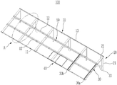
도 2는 본 발명의 일 실시예에 따른 태양광모듈프레임이다. 2 is a solar module frame according to an embodiment of the present invention.
도 2를 참고하면, 태양광모듈프레임(100)은, 레일브라켓부(10) 및 프레임부(20)를 포함할 수 있다. Referring to FIG. 2, the
레일브라켓부(10)는 프레임부(20)를 따라 복수개가 평행하게 설치될 수 있다. 레일브라켓부(10)는 지면과 이격되어 설치될 수 있다. 레일브라켓부(10)는 복수개의 레일브라켓(11, 12, 13)을 포함할 수 있다. 복수개의 레일브라켓(11, 12, 13)은 서로 이격될 수 있다. 레일브라켓(11, 12, 13)과 인접한 레일브라켓(11, 12, 13) 사이로 태양광패널이 위치할 수 있다. 다른 예로 태양광패널은 레일브라켓(11,12,13) 상부에서 레일브라켓(11,12,13)에 연결될 수 있다. A plurality of
프레임부(20)는 포스트(21), 지지프레임(22) 및 경사프레임(23)을 포함할 수 있다. 프레임부(20)는 복수개가 서로 이격되어 설치될 수 있다. 즉, 프레임부(20)는 레일브라켓(11,12,13)을 지지하는 기초로써, 레일브라켓(11,12,13)에 안착되는 태양광패널의 무게를 지지하기 위해 복수개가 설치될 수 있다. The
포스트(21)는 수직으로 연결될 수 있다. 포스트(21)는 지면과 연결되며 경사지도록 형성될 수도 있다. 예를 들면, 포스트(21) 상단은 대략 지면으로부터 7m 정도로 형성된다. 빌딩의 크기와 태양광패널의 설치수에 따라 포스트(21)의 높이는 더 크게 형성될 수 있다. The
지지프레임(22)은 포스트(21) 상단에 연결되고 지면과 연결될 수 있다. 즉 지지프레임(22)은 포스트(21)를 지면으로부터 지지할 수 있다. 예를 들면, 지지프레임(22)은 포스트(21)상단에서 경사져 지면을 향해 지면과 연결될 수 있다. 포스트(21)와 지지프레임(22) 연결로, 태양광모듈프레임(100)의 전체적인 형상이 삼각형일 수 있다. 지지프레임(22)에 복수개의 레일브라켓(11, 12, 13)이 서로 이격되어 배치되고 연결될 수 있다. 경사프레임(23)은 포스트(21)와 지지프레임(22) 사이를 연결할 수 있다. 포스트(21)의 상부와 이격된 위치에서 지지프레임(22)의 중간 위치에 연결될 수 있다. 이를 통해, 지지프레임(22)에 연결된 레일브라켓부(10)의 자중 및 레일브라켓부(10)에 연결되는 태양광패널의 무게를 견딜 수 있다. The
지지프레임(22)은 레일브라켓부(10)의 배치방향과 수직한 방향으로 배치되며, 상기 레일브라켓부(10) 하단으로 연결될 수 있다. 프레임부(20)는 레일브라켓부(10)를 지지하며, 지면에 연결될 수 있다. 예를 들면, 프레임부(20)의 포스트(21)는 지면, 지붕 또는 건물에 연결될 수 있다. 포스트(21)는 지면으로부터 수직하고 지지프레임(22)에 연결되는 경사프레임을 포함할 수 있다. The
결합부(50)는 레일브라켓 중간에 위치할 수 있다. 즉, 일정 길이의 레일브라켓(11, 12, 13)은 여러 개가 결합부(50)를 매개로 연결될 수 있다. 이를 통해 수평적으로 매우 긴 태양광모듈프레임(100)을 형성할 수 있다. 결합부(50)의 위치는 태양광패널의 고정위치와 상이한 위치에 형성할 수 있다. Coupling
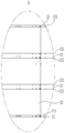
도 3은 도 2에 도시된 태양광모듈프레임의 A를 확대한 도면이다. 3 is an enlarged view of A of the solar module frame shown in FIG. 2.
도 3을 참고하면, 레일브라켓부(10)는 복수개의 레일브라켓(11, 12, 13)을 포함할 수 있다. 제1 레일브라켓(11)은 지면과 인접하게 설치될 수 있다. 제1 레일브라켓(11)은 지면을 향하는 방향과 반대방향으로 돌출된 레일바닥면(111)이 형성될 수 있다. 레일바닥면(111)은 제1 레일브라켓(11)의 상부와 단차가 형성될 수 있다. 예를 들면, 제1 레일브라켓(11)은 사각파이프의 하면에 레일바닥면(111)이 측면으로 돌출된 형태일 수 있다. 레일바닥면(111)은 제1 레일브라케(11)으로부터 2~ 5cm로 돌출된다. 레일바닥면(111)에는 태양광패널이 가결합되어 이동될 수 있다. 다른 예로, 레일바닥면(111)과 태양광패널 사이에는 바퀴가 위치할 수 있으며, 또 다른예로, 레일바닥면(111)에는 캐리어(40)가 연결될 수 있다. 이때, 레일바닥면(111)에는 캐리어(40)의 롤러부(43)가 안착될 수 있다. Referring to Figure 3, the
제2 레일브라켓(12)은 제1 레일브라켓(11)과 이격되어 배치될 수 있다. 제2 레일브라켓(12)은 양측에 제2 레일바닥면(121)이 돌출될 수 있다. 이에 따라 제2 레일브라켓(12)과 제1 레일브라켓(11)이 마주보는 면에 제2 레일바닥면(121)이 제2 레일브라켓(12)의 양측으로 형성될 수 있다. 제2 레일바닥면(121)는 태양광패널이 안착될 수 있다. 다른 예로, 제2 레일바닥면(121)에는 캐리어(40)가 안착될 수 있다. The
제2 레일브라켓(12)은 복수개일 수 있다. 즉, 태양광모듈프레임(100)에 태양광패널이 복수의 단으로 형성될 수 있다. 예를 들면, 일반 가정의 경우에는 2단으로 설치될 수 있으며, 공공기관등에는 3단 또는 빌딩의 경우 4단 내지 5단으로 설치될 수 있다. 이때, 제2 레일브라켓(12)은 태양광패널이 설치되는 단에 따라 복수개로 형성될 수 있다. The
제3 레일브라켓(13)은 제2 레일브라켓(12)과 이격되어 배치될 수 있다. 제3 레일브라켓(13)의 형상은 제1 레일브라켓(11)과 동일하게 형성될 수 있다. 즉, 제3 레일브라켓(13)은 프레임부(20)의 포스트(21)의 상부에 연결될 수 있다. 제3 레일브라켓(13)은 제2 레일브라켓(12)을 향하는 방향으로 제3 레일바닥면(131)이 형성될 수 있다. The
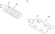
도 4는 도 3에 도시한 결합부의 사시도이다. 4 is a perspective view of the coupling portion shown in FIG. 3.
한편, 도 4를 참고하면, 결합부(50)는 제1 결합부재(50a) 및 제2 결합부재(50b)를 포함할 수 있다. 제1 결합부재(50a)는 제1 결합판(51) 및 제2 결합판(52)을 포함할 수 있다. 제1 결합판(51)과 제2 결합판(52)은 수직하게 연결될 수 있다. Meanwhile, referring to FIG. 4, the
제2 결합부재(50b)는 중심부가 상방을 향해 절곡된 제2 돌출턱(56) 및 제2 돌출턱(56)의 양 측면에서 돌출 형성된 제3 결합판(55)을 포함할 수 있다.The
제2 결합부재(50b)는 복수개의 제2 레일브라켓(12)과 결합될 수 있다. 예를 들어, 제2 돌출턱(56)은 제2 레일브라켓(12)에 삽입되며, 제3 결합판(55)은 제2 레일바닥면(121)과 연결될 수 있다.The
제1 결합부재(50a) 및 제2 결합부재(50b)에 형성된 복수개의 피스홀(53, 57)을 통해 나사나 결합 수단을 관통시켜 제1 레일브라켓(11)과 제3 레일브라켓(13) 및 제2 레일브라켓(12)은 복수개가 연결될 수 있다. The
태양광모듈프레임(100)은 결합부(50)의 개수를 상황에 따라 다르게 함으로써, 태양광 모듈을 설치하려는 지역 및 생산하려는 전력의 크기 등 상황에 따라 레일브라켓부(10) 열 길이를 결정할 수 있다. 설치 지역의 넓이가 넓을 경우, 길이를 연장할 수 있고, 설치 지역의 넓이가 좁을 경우 결합부를 통해 열의 길이를 줄일 수 있다.The
이를 통해, 태양광모듈프레임(100)은 상황에 따라 태양광 모듈이 설치되는 면적을 조절할 수 있다.Through this, the
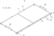
도 5는 도 2에 도시된 수직프레임의 사시도이다. 5 is a perspective view of the vertical frame shown in FIG. 2.
도 5를 참고하면, 태양광모듈프레임(100)은 수직레일(30)을 더 포함할 수 있다.5, the
수직레일(30)은 레일브라켓부(10)의 길이 방향과 수직한 방향으로 연장 형성될 수 있다. 수직레일(30)은 제1 수직레일(30a) 및 제2 수직레일(30b)를 포함할 수 있다. 제1 수직레일(30a)과 제2 수직레일(30b)은 서로 이격되어 레일브라켓부(10)에 연결되며, 제1 수직레일(30a)과 제2 수직레일(30b)에 캐리어(40)의 롤러부(43)가 안착되어 이동할 수 있다. The
수직레일(30)은 레일몸체(31), 걸림턱(38), 제1 경사면(330), 제2 경사면(35) 및 제3 경사면(37)을 포함할 수 있다.The
레일몸체(31)는 레일브라켓부(10)의 길이 방향과 수직한 방향으로 연장 형성된 기둥 형태로 형성될 수 있다. 또한, 레일몸체(31)의 일측면에는 복수개의 레일벽체(311)가 돌출 형성될 수 있다.The
복수개의 레일벽체(311)는 상호간 이격되어 위치하여, 레일벽체(311)의 사이에는 레일홈(313)이 형성될 수 있다. 이때, 레일홈(313)의 폭은 캐리어(40)의 제1 롤러(431)에 대응되도록 구성될 수 있다.The plurality of
또한, 레일몸체(31)의 양 단부에는 레일벽체(311)가 돌출된 방향과 반대 방향으로 걸림턱(38)이 형성될 수 있다. 상단부의 걸림턱(38)은 레일브라켓부(10)의 제3 레일브라켓(13) 또는 제2 레일브라켓(12)에 접하는 방식으로 수직레일(30)이 레일브라켓부(10)에 걸리도록 할 수 있다. 또한, 하단부의 걸림턱(38)은 제1 레일브라켓(11)에 접하며 수직레일(30)이 레일브라켓부(10)에 의해 지지되도록 할 수 있다.In addition, the locking
제1 경사면(330)은 레일몸체(31)의 하단부에서 레일브라켓부(10)의 길이 방향으로 연장 형성될 수 있다. 이때, 제1 경사면(330)은 일단부가 레일브라켓부(10)의 레일바닥면(111, 121, 131)에 접하도록 비스듬하게 연장 형성될 수 있다.The first
또한, 제1 경사면(330)이 형성된 위치에 인접하게 위치한 레일벽체(311)에는 캐리어(40)의 제1 롤러(431)가 레일몸체(31)의 레일홈(313)에 삽입될 수 있도록 제1 삽입공간(331)이 형성될 수 있다.In addition, the
제3 경사면(37)은 레일몸체(31)의 상단부에서 레일브라켓부(10)의 길이 방향으로 연장 형성될 수 있다. 이때, 제3 경사면(37)은 일단부가 레일브라켓부(10)의 제2 레일바닥면(121) 또는 제3 레일바닥면(131)와 접하도록 비스듬하게 연장 형성될 수 있다.The third
또한, 제3 경사면(37)이 형성된 위치에 인접하게 위치한 레일벽체(311)에는 캐리어(40)의 제1 롤러(431)가 레일몸체(31)의 레일홈(313)에 삽입될 수 있도록 제3 삽입공간(371)이 형성될 수 있다.In addition, the
제2 경사면(35)은 제1 경사면(330) 또는 제3 경사면(37) 사이의 레일브라켓부(10)의 길이 방향으로 연장 형성될 수 있다. 이때, 제2 경사면(35)은 일단부가 레일브라켓부(10)의 제3 레일바닥면(131)와 접하도록 비스듬하게 연장 형성될 수 있다.The second
또한, 제2 경사면(35)이 형성된 위치에 인접하게 위치한 레일벽체(611)에는 캐리어(40)의 제1 롤러(431)가 레일몸체(31)의 레일홈(313)에 삽입될 수 있도록 제2 삽입공간(351)이 형성될 수 있다.In addition, the
레일브라켓부(10)의 길이 방향을 따라 슬라이딩 이동되는 캐리어(40)는 제1 경사면(330), 제2 경사면(35) 또는 제3 경사면(37)을 통해 제1 롤러(431)가 레일몸체(31)의 상면으로 이동될 수 있다.The
이후, 캐리어(40)를 수직레일(30)의 길이 방향으로 이동되도록 하면, 제1 롤러(431)는 회전판에 의해 회전하며 수직레일(30)의 길이 방향으로 회전하게 된다.Then, when the
이를 통해, 태양광모듈프레임(100)은 수직레일(30)로 캐리어(40)가 레일브라켓부(10)의 길이 방향뿐만 아니라, 레일브라켓부(10)와 수직한 방향으로 이동되도록 할 수 있다.Through this, the
도 6은 도 2에 도시된 캐리어의 사시도이다. 6 is a perspective view of the carrier shown in FIG. 2.
도 5를 참고하면, 캐리어(40)는 이송부(41), 롤러부(43) 및 손잡이부(44)를 포함할 수 있다. 이송부(41)는, 레일브라켓(11,12,13)과 인접한 레일브라켓(11,12,13) 사이로 위치할 수 있다. 롤러부(43)는 이송부(41) 하부로 연결되어 레일브라켓(11,12,13)의 레일바닥면(111,121,131)에 접촉될 수 있다. 롤러부(43)는 제1 롤러(431)와 제2 롤러(432)를 포함할 수 있다. 제1 롤러(431)는 레일바닥면(111)을 향하여 레일바닥면(111)에 접촉되고 제2 롤러(432)는 제1 롤러(431)의 측면으로 연결되어 레일바닥면(111)의 측벽에 접촉될 수 있다. 이를 통해 캐리어(40)는 레일브라켓(11,12,13)과 인접한 레일브라켓(11,12,13) 사이에서 안정적으로 이동될 수 있다. 즉, 캐리어(40)는 태양광패널의 무게를 지탱하면서 태양광모듈프레임(100)에 연결되면서 이동될 수 있다. Referring to FIG. 5, the
손잡이부(44)는 캐리어(40) 상부에 형성될 수 있으며, 작업자에게 보다 용이하게 캐리어(40)를 이동시킬 수 있는 수단을 제공할 수 있다. 또한, 양측으로 형성된 손잡이부(44)에 의해 태양광패널은 캐리어(40)로부터 이탈되지 않고 이동될 수 있다. 태양광패널이 이동된 뒤, 손잡이부(44)는 탈거될 수 있다. The handle portion 44 may be formed on the
지지부(45)는 캐리어(40) 상부에 형성되고, 태양광패널은 지지부(45)에 의해 캐리어(40)에 보다 안정적으로 안착될 수 있다. 즉, 태양광패널의 자중에 의해 지면을 향하여 태양광패널이 이동되는 것을 지지부에 의해 방지할 수 있다. The
제1 손잡이(441)와 제2 손잡이(442) 사이로 복수개의 베어링(42)이 연결될 수 있다. 베어링(42)은 이송부(41)에 연결되며, 베어링(42) 상부로 태양광패널이 안착될 수 있다. 태양광패널은 베어링(42)에 의해 캐리어(40)에서 미끌어져 제거될 수 있다. A plurality of
본 발명을 앞서 기재한 바에 따라 바람직한 실시예를 통해 설명하였지만, 본 발명은 이에 한정되지 않으며 다음에 기재하는 특허청구범위의 개념과 범위를 벗어나지 않는 한, 다양한 수정 및 변형이 가능하다는 것을 본 발명이 속하는 기술 분야에 종사하는 자들은 쉽게 이해할 것이다.Although the present invention has been described through preferred embodiments as described above, the present invention is not limited to this, and the present invention shows that various modifications and variations are possible without departing from the concept and scope of the following claims. Those in the field of technology to which they belong will readily understand.
100: 태양광모듈프레임
10: 레일브라켓부
11: 제1 레일브라켓
111: 레일바닥면
12: 제2 레일브라켓
121: 제2 레일바닥면
13: 제3 레일브라켓
131: 제3 레일바닥면
20: 프레임부
21: 포스트
22: 지지프레임
23: 경사프레임
30: 수직레일
30a: 제1 수직레일
30b: 제2 수직레일
31: 레일몸체
311: 레일벽체
313: 레일홈
330: 제1 경사면
331: 제1 삽입공간
35: 제2 경사면
351: 제2 삽입공간
37: 제3 경사면
371: 제3 삽입공간
38: 걸림턱
50: 결합부
50a: 제1 결합부재
50b: 제2 결합부재
51: 제1 결합판
52: 제2 결합판
53, 57: 피스홀
55: 제3 결합판
56: 제2 돌출턱
40: 캐리어
41: 이송부
42: 베어링
43: 롤러부
431: 제1 롤러
432: 제2 롤러
44: 손잡이부
441: 제1 손잡이
442: 제2 손잡이
45: 지지부100: solar module frame 10: rail bracket part
11: first rail bracket 111: rail bottom surface
12: second rail bracket 121: second rail bottom surface
13: third rail bracket 131: third rail bottom surface
20: frame part 21: post
22: Support frame 23: Inclined frame
30:
30b: second vertical rail 31: rail body
311: rail wall 313: rail groove
330: first slope 331: first insertion space
35: second slope 351: second insertion space
37: 3rd slope 371: 3rd insertion space
38: engaging jaw 50: engaging portion
50a: first coupling
51: first coupling plate 52: second coupling plate
53, 57: Peace hole 55: Third coupling plate
56: second protrusion
40: carrier 41: transfer unit
42: bearing 43: roller
431: first roller 432: second roller
44: handle 441: first handle
442: second handle 45: support
Claims (11)
상기 태양광패널을 상기 지면과 평행한 방향으로 이동시키는 제1 이동단계; 및
상기 태양광패널을 상기 태양광모듈프레임에 고정하는 고정단계를 포함하는 태양광패널 설치방법. An arrangement step of temporarily coupling the photovoltaic panel to the photovoltaic module frame installed obliquely to the ground;
A first moving step of moving the solar panel in a direction parallel to the ground; And
A method of installing a solar panel comprising a fixing step of fixing the solar panel to the solar module frame.
상기 제1 이동단계와 상기 고정단계 사이에,
상기 태양광패널을 상기 태양광모듈프레임을 따라 하부, 중간부 및 상부로 이동시키는 제2 이동단계를 더 포함하는 태양광패널 설치방법. According to claim 1,
Between the first moving step and the fixing step,
A method of installing a photovoltaic panel further comprising a second movement step of moving the photovoltaic panel to the lower, middle and upper portions along the photovoltaic module frame.
상기 제2 이동단계는,
상기 태양광패널이 상기 태양광모듈프레임 일측으로 이동이 완료된 후 이뤄지는 태양광패널 설치방법. According to claim 2,
The second moving step,
A method of installing a photovoltaic panel after the photovoltaic panel is moved to one side of the photovoltaic module frame.
상기 제2 이동단계는,
상기 태양광패널이 상기 태양광모듈프레임의 하부에서 중간부로 이동되었을때, 상기 지면과 평행하며, 상기 제1 이송방향과 반대방향으로 이동시키는 제3 이동단계를 포함하는 태양광패널 설치방법. According to claim 2,
The second moving step,
When the solar panel is moved from the lower portion to the middle of the photovoltaic module frame, the solar panel installation method comprising a third moving step parallel to the ground, and moving in a direction opposite to the first transfer direction.
상기 제3 이동단계는,
상기 태양광패널이 상기 태양광모듈프레임의 중간부에서 상부로 이동되었을때, 상기 지면과 평행하며, 상기 제1 이송방향과 반대방향으로 이동시키는 제4 이동단계를 포함하는 태양광패널 설치방법. According to claim 4,
The third moving step,
When the solar panel is moved from the middle of the photovoltaic module frame to the top, the solar panel installation method comprising a fourth movement step of moving in the direction opposite to the first transfer direction, parallel to the ground.
상기 배치단계 전에,
상기 태양광모듈프레임에 캐리어를 가결합하는 단계; 및
상기 태양광패널을 상기 캐리어에 안착시키는 단계를 포함하는 태양광패널 설치방법. According to claim 1,
Before the placement step,
Temporarily coupling a carrier to the solar module frame; And
A method of installing a solar panel comprising the step of seating the solar panel on the carrier.
상기 고정단계 전에,
상기 캐리어의 손잡이를 탈거하는 단계;
상기 태양광패널을 상기 캐리어 일측으로 이동시키는 단계;
상기 캐리어를 상기 태양광모듈프레임으로부터 제거하는 단계를 더 포함하는 태양광패널 설치방법. The method of claim 6,
Before the fixing step,
Removing the handle of the carrier;
Moving the solar panel to one side of the carrier;
And removing the carrier from the photovoltaic module frame.
상기 지지프레임에 서로 이격되어 배치되며, 배치방향으로 레일바닥면이 형성된 복수개의 레일브라켓으로 이루어진 레일브라켓부를 포함하는 태양광모듈프레임. A frame part including a post connected to the ground, a support frame connected to the upper portion of the post and leading to the ground, and an inclined frame of the post and the support frame; And
A solar module frame comprising a rail bracket part formed of a plurality of rail brackets spaced apart from each other on the support frame and having a rail bottom surface in the arrangement direction.
복수개의 상기 레일브라켓의 배치방향으로 연결되는 수직브라켓을 포함하는 태양광모듈프레임.The method of claim 8,
A photovoltaic module frame including a vertical bracket connected to a plurality of rail brackets in an arrangement direction.
상기 레일브라켓부는,
상기 레일바닥면이 형성된 제1 레일브라켓;
상기 제1 레일브라켓과 이격되어 설치되며 양측에 상기 레일바닥면에 대응되는 위치로 돌출된 제2 레일바닥면을 가지는 제2 레일브라켓; 및
상기 제2 레일브라켓과 이격되며 상기 제2 레일바닥면을 향하여 돌출된 제3레일바닥면을 가지는 제3 레일브라켓을 포함하는 태양광모듈프레임. The method of claim 9,
The rail bracket portion,
A first rail bracket on which the rail bottom surface is formed;
A second rail bracket spaced apart from the first rail bracket and having second rail bottom surfaces protruding to positions corresponding to the rail bottom surfaces on both sides; And
A solar module frame including a third rail bracket spaced apart from the second rail bracket and having a third rail bottom surface protruding toward the second rail bottom surface.
상기 레일브라켓과 인접한 레일브라켓 사이로 위치하는 이송부;
상기 이송부 하부로 연결되어 상기 레일바닥면에 접촉되는 제1 롤러와 상기 제1 롤러 측면방향으로 연결되어 상기 레일바닥면의 측벽에 접촉되는 제2 롤러를 가지는 롤러부;
상기 이송부의 상부에 탈착되도록 연결된 손잡이부; 및
상기 이송부의 상부에 연결되는 베어링부를 가지는 캐리어를 더 포함하는 태양광모듈프레임.The method of claim 8,
A transfer part positioned between the rail bracket and an adjacent rail bracket;
A roller unit having a first roller connected to the lower portion of the transfer unit and contacting the rail bottom surface and a second roller connected in a side direction of the first roller and contacting a side wall of the rail bottom surface;
A handle portion connected to be detached from the upper portion of the transfer portion; And
Solar module frame further comprises a carrier having a bearing portion connected to the upper portion of the transport.
Priority Applications (1)
| Application Number | Priority Date | Filing Date | Title |
|---|---|---|---|
| KR1020190001286A KR102236909B1 (en) | 2019-01-04 | 2019-01-04 | Installation method of solar panel and frame for solar panel |
Applications Claiming Priority (1)
| Application Number | Priority Date | Filing Date | Title |
|---|---|---|---|
| KR1020190001286A KR102236909B1 (en) | 2019-01-04 | 2019-01-04 | Installation method of solar panel and frame for solar panel |
Publications (2)
| Publication Number | Publication Date |
|---|---|
| KR20200085137A true KR20200085137A (en) | 2020-07-14 |
| KR102236909B1 KR102236909B1 (en) | 2021-04-06 |
Family
ID=71526890
Family Applications (1)
| Application Number | Title | Priority Date | Filing Date |
|---|---|---|---|
| KR1020190001286A KR102236909B1 (en) | 2019-01-04 | 2019-01-04 | Installation method of solar panel and frame for solar panel |
Country Status (1)
| Country | Link |
|---|---|
| KR (1) | KR102236909B1 (en) |
Cited By (1)
| Publication number | Priority date | Publication date | Assignee | Title |
|---|---|---|---|---|
| KR102366428B1 (en) | 2021-04-19 | 2022-02-23 | 조현석 | Solar rotary module |
Families Citing this family (1)
| Publication number | Priority date | Publication date | Assignee | Title |
|---|---|---|---|---|
| KR102434849B1 (en) | 2021-05-28 | 2022-08-23 | 신라대학교 산학협력단 | Polymer compositions having high flame retardancy with high strength and high radiating properties and solar system frame thereof |
Citations (2)
| Publication number | Priority date | Publication date | Assignee | Title |
|---|---|---|---|---|
| JP2011124317A (en) * | 2009-12-09 | 2011-06-23 | Toshiba Plant Systems & Services Corp | Device and method for mounting solar cell module |
| JP2014190033A (en) * | 2013-03-27 | 2014-10-06 | Green Technology Institute & Co Ltd | Trestle for installing solar battery panels and installation method |
-
2019
- 2019-01-04 KR KR1020190001286A patent/KR102236909B1/en active IP Right Grant
Patent Citations (2)
| Publication number | Priority date | Publication date | Assignee | Title |
|---|---|---|---|---|
| JP2011124317A (en) * | 2009-12-09 | 2011-06-23 | Toshiba Plant Systems & Services Corp | Device and method for mounting solar cell module |
| JP2014190033A (en) * | 2013-03-27 | 2014-10-06 | Green Technology Institute & Co Ltd | Trestle for installing solar battery panels and installation method |
Cited By (1)
| Publication number | Priority date | Publication date | Assignee | Title |
|---|---|---|---|---|
| KR102366428B1 (en) | 2021-04-19 | 2022-02-23 | 조현석 | Solar rotary module |
Also Published As
| Publication number | Publication date |
|---|---|
| KR102236909B1 (en) | 2021-04-06 |
Similar Documents
| Publication | Publication Date | Title |
|---|---|---|
| KR101813068B1 (en) | Building integrated photovoltaic in wall | |
| KR101733976B1 (en) | Solar cell module mounting apparatus for installation on veranda | |
| US20120167957A1 (en) | Solar panel installation systems and methods | |
| KR101902126B1 (en) | Solar panel mounting deviec | |
| KR20200085137A (en) | Installation method of solar panel and frame for solar panel | |
| KR20130116085A (en) | A roof fixing type support structure of solar panel | |
| KR20130116084A (en) | A roof fixing type support structure of solar panel | |
| JP2012054420A (en) | Solar cell panel frame and solar cell device | |
| KR101176993B1 (en) | Apparatus for supporting solar module | |
| KR101915465B1 (en) | Clamp for solar module | |
| JP2014140302A (en) | Solar power generating apparatus and triangular metal fitting for inclination angle setting | |
| CN215474717U (en) | Photovoltaic board cleans machine people transition device | |
| KR101215625B1 (en) | Apparatus for supporting solar module | |
| KR102085325B1 (en) | Mounter for sola module | |
| KR101389112B1 (en) | Waterside solar photovoltaic system | |
| KR101326798B1 (en) | Solar photovoltatic power generation | |
| KR102210126B1 (en) | Supporting structure of solar panel | |
| CN219087053U (en) | Photovoltaic power generation device convenient to install | |
| CN216180314U (en) | Solar photovoltaic flexible support maintenance device | |
| CN220811612U (en) | Hoisting tool | |
| CN207251525U (en) | A kind of color steel tile photovoltaic mounting assembly and color steel tile | |
| CN218829723U (en) | Photovoltaic power generation board mounting bracket | |
| CN219213647U (en) | Automatic erect and prop installation device that punches | |
| JP2017133294A (en) | Installation structure of functional panel | |
| KR102216763B1 (en) | Lightweight prefabricated structures for installation of solar modules |
Legal Events
| Date | Code | Title | Description |
|---|---|---|---|
| E902 | Notification of reason for refusal | ||
| AMND | Amendment | ||
| E601 | Decision to refuse application | ||
| X091 | Application refused [patent] | ||
| AMND | Amendment | ||
| X701 | Decision to grant (after re-examination) | ||
| GRNT | Written decision to grant |