KR20200080276A - Spatial and temporal encoding of acoustic waveforms for whole composite transmission aperture imaging - Google Patents
Spatial and temporal encoding of acoustic waveforms for whole composite transmission aperture imaging Download PDFInfo
- Publication number
- KR20200080276A KR20200080276A KR1020207015032A KR20207015032A KR20200080276A KR 20200080276 A KR20200080276 A KR 20200080276A KR 1020207015032 A KR1020207015032 A KR 1020207015032A KR 20207015032 A KR20207015032 A KR 20207015032A KR 20200080276 A KR20200080276 A KR 20200080276A
- Authority
- KR
- South Korea
- Prior art keywords
- waveforms
- transmission
- acoustic
- transducer
- delay
- Prior art date
Links
- 230000005540 biological transmission Effects 0.000 title claims abstract description 243
- 239000002131 composite material Substances 0.000 title claims abstract description 75
- 238000003384 imaging method Methods 0.000 title claims abstract description 35
- 230000002123 temporal effect Effects 0.000 title claims abstract description 17
- 238000000034 method Methods 0.000 claims abstract description 147
- 230000008054 signal transmission Effects 0.000 claims abstract description 9
- 239000000523 sample Substances 0.000 claims description 74
- 238000012545 processing Methods 0.000 claims description 42
- 230000001934 delay Effects 0.000 claims description 41
- 238000004891 communication Methods 0.000 claims description 15
- 230000003111 delayed effect Effects 0.000 claims description 9
- 238000009827 uniform distribution Methods 0.000 claims description 8
- 230000006835 compression Effects 0.000 claims description 5
- 238000007906 compression Methods 0.000 claims description 5
- 238000002592 echocardiography Methods 0.000 abstract description 14
- 238000005070 sampling Methods 0.000 abstract description 9
- 238000002059 diagnostic imaging Methods 0.000 abstract description 4
- 239000013598 vector Substances 0.000 description 47
- 230000000875 corresponding effect Effects 0.000 description 38
- 239000011159 matrix material Substances 0.000 description 30
- 230000008569 process Effects 0.000 description 28
- 238000010586 diagram Methods 0.000 description 21
- 238000012285 ultrasound imaging Methods 0.000 description 20
- 238000005516 engineering process Methods 0.000 description 18
- 230000006870 function Effects 0.000 description 17
- 238000002604 ultrasonography Methods 0.000 description 11
- 230000001427 coherent effect Effects 0.000 description 9
- 238000005457 optimization Methods 0.000 description 9
- 230000033001 locomotion Effects 0.000 description 8
- IUVCFHHAEHNCFT-INIZCTEOSA-N 2-[(1s)-1-[4-amino-3-(3-fluoro-4-propan-2-yloxyphenyl)pyrazolo[3,4-d]pyrimidin-1-yl]ethyl]-6-fluoro-3-(3-fluorophenyl)chromen-4-one Chemical compound C1=C(F)C(OC(C)C)=CC=C1C(C1=C(N)N=CN=C11)=NN1[C@@H](C)C1=C(C=2C=C(F)C=CC=2)C(=O)C2=CC(F)=CC=C2O1 IUVCFHHAEHNCFT-INIZCTEOSA-N 0.000 description 7
- 238000000926 separation method Methods 0.000 description 7
- 238000003491 array Methods 0.000 description 6
- 230000002596 correlated effect Effects 0.000 description 5
- 230000006872 improvement Effects 0.000 description 5
- 238000004422 calculation algorithm Methods 0.000 description 4
- 230000003902 lesion Effects 0.000 description 4
- 230000035515 penetration Effects 0.000 description 4
- 230000015572 biosynthetic process Effects 0.000 description 3
- 238000013461 design Methods 0.000 description 3
- 238000010801 machine learning Methods 0.000 description 3
- 230000004044 response Effects 0.000 description 3
- 238000001228 spectrum Methods 0.000 description 3
- 238000013459 approach Methods 0.000 description 2
- 230000006399 behavior Effects 0.000 description 2
- 238000004364 calculation method Methods 0.000 description 2
- 230000008859 change Effects 0.000 description 2
- 230000000295 complement effect Effects 0.000 description 2
- 238000009826 distribution Methods 0.000 description 2
- 230000000694 effects Effects 0.000 description 2
- 238000001914 filtration Methods 0.000 description 2
- 238000000819 phase cycle Methods 0.000 description 2
- 238000004088 simulation Methods 0.000 description 2
- 238000012549 training Methods 0.000 description 2
- 230000000007 visual effect Effects 0.000 description 2
- 241001465754 Metazoa Species 0.000 description 1
- 241000699670 Mus sp. Species 0.000 description 1
- 239000004677 Nylon Substances 0.000 description 1
- 230000003044 adaptive effect Effects 0.000 description 1
- 238000004458 analytical method Methods 0.000 description 1
- 230000002238 attenuated effect Effects 0.000 description 1
- 230000008901 benefit Effects 0.000 description 1
- 230000010267 cellular communication Effects 0.000 description 1
- 230000021615 conjugation Effects 0.000 description 1
- 238000013500 data storage Methods 0.000 description 1
- 230000001066 destructive effect Effects 0.000 description 1
- 230000001627 detrimental effect Effects 0.000 description 1
- 230000005284 excitation Effects 0.000 description 1
- 238000010295 mobile communication Methods 0.000 description 1
- 229920001778 nylon Polymers 0.000 description 1
- 238000012634 optical imaging Methods 0.000 description 1
- 230000008447 perception Effects 0.000 description 1
- 238000012805 post-processing Methods 0.000 description 1
- 230000000644 propagated effect Effects 0.000 description 1
- 230000002441 reversible effect Effects 0.000 description 1
- 238000009738 saturating Methods 0.000 description 1
- 101150075118 sub1 gene Proteins 0.000 description 1
- 208000024891 symptom Diseases 0.000 description 1
- 238000003786 synthesis reaction Methods 0.000 description 1
- 238000012546 transfer Methods 0.000 description 1
Images


Classifications
-
- G—PHYSICS
- G01—MEASURING; TESTING
- G01S—RADIO DIRECTION-FINDING; RADIO NAVIGATION; DETERMINING DISTANCE OR VELOCITY BY USE OF RADIO WAVES; LOCATING OR PRESENCE-DETECTING BY USE OF THE REFLECTION OR RERADIATION OF RADIO WAVES; ANALOGOUS ARRANGEMENTS USING OTHER WAVES
- G01S15/00—Systems using the reflection or reradiation of acoustic waves, e.g. sonar systems
- G01S15/88—Sonar systems specially adapted for specific applications
- G01S15/89—Sonar systems specially adapted for specific applications for mapping or imaging
- G01S15/8906—Short-range imaging systems; Acoustic microscope systems using pulse-echo techniques
- G01S15/8959—Short-range imaging systems; Acoustic microscope systems using pulse-echo techniques using coded signals for correlation purposes
-
- A—HUMAN NECESSITIES
- A61—MEDICAL OR VETERINARY SCIENCE; HYGIENE
- A61B—DIAGNOSIS; SURGERY; IDENTIFICATION
- A61B8/00—Diagnosis using ultrasonic, sonic or infrasonic waves
- A61B8/44—Constructional features of the ultrasonic, sonic or infrasonic diagnostic device
- A61B8/4483—Constructional features of the ultrasonic, sonic or infrasonic diagnostic device characterised by features of the ultrasound transducer
- A61B8/4488—Constructional features of the ultrasonic, sonic or infrasonic diagnostic device characterised by features of the ultrasound transducer the transducer being a phased array
-
- A—HUMAN NECESSITIES
- A61—MEDICAL OR VETERINARY SCIENCE; HYGIENE
- A61B—DIAGNOSIS; SURGERY; IDENTIFICATION
- A61B8/00—Diagnosis using ultrasonic, sonic or infrasonic waves
- A61B8/52—Devices using data or image processing specially adapted for diagnosis using ultrasonic, sonic or infrasonic waves
- A61B8/5207—Devices using data or image processing specially adapted for diagnosis using ultrasonic, sonic or infrasonic waves involving processing of raw data to produce diagnostic data, e.g. for generating an image
-
- A—HUMAN NECESSITIES
- A61—MEDICAL OR VETERINARY SCIENCE; HYGIENE
- A61B—DIAGNOSIS; SURGERY; IDENTIFICATION
- A61B8/00—Diagnosis using ultrasonic, sonic or infrasonic waves
- A61B8/52—Devices using data or image processing specially adapted for diagnosis using ultrasonic, sonic or infrasonic waves
- A61B8/5269—Devices using data or image processing specially adapted for diagnosis using ultrasonic, sonic or infrasonic waves involving detection or reduction of artifacts
-
- A—HUMAN NECESSITIES
- A61—MEDICAL OR VETERINARY SCIENCE; HYGIENE
- A61B—DIAGNOSIS; SURGERY; IDENTIFICATION
- A61B8/00—Diagnosis using ultrasonic, sonic or infrasonic waves
- A61B8/58—Testing, adjusting or calibrating the diagnostic device
- A61B8/587—Calibration phantoms
-
- G—PHYSICS
- G01—MEASURING; TESTING
- G01S—RADIO DIRECTION-FINDING; RADIO NAVIGATION; DETERMINING DISTANCE OR VELOCITY BY USE OF RADIO WAVES; LOCATING OR PRESENCE-DETECTING BY USE OF THE REFLECTION OR RERADIATION OF RADIO WAVES; ANALOGOUS ARRANGEMENTS USING OTHER WAVES
- G01S15/00—Systems using the reflection or reradiation of acoustic waves, e.g. sonar systems
- G01S15/88—Sonar systems specially adapted for specific applications
- G01S15/89—Sonar systems specially adapted for specific applications for mapping or imaging
- G01S15/8906—Short-range imaging systems; Acoustic microscope systems using pulse-echo techniques
- G01S15/8909—Short-range imaging systems; Acoustic microscope systems using pulse-echo techniques using a static transducer configuration
- G01S15/8915—Short-range imaging systems; Acoustic microscope systems using pulse-echo techniques using a static transducer configuration using a transducer array
- G01S15/8927—Short-range imaging systems; Acoustic microscope systems using pulse-echo techniques using a static transducer configuration using a transducer array using simultaneously or sequentially two or more subarrays or subapertures
-
- G—PHYSICS
- G01—MEASURING; TESTING
- G01S—RADIO DIRECTION-FINDING; RADIO NAVIGATION; DETERMINING DISTANCE OR VELOCITY BY USE OF RADIO WAVES; LOCATING OR PRESENCE-DETECTING BY USE OF THE REFLECTION OR RERADIATION OF RADIO WAVES; ANALOGOUS ARRANGEMENTS USING OTHER WAVES
- G01S15/00—Systems using the reflection or reradiation of acoustic waves, e.g. sonar systems
- G01S15/88—Sonar systems specially adapted for specific applications
- G01S15/89—Sonar systems specially adapted for specific applications for mapping or imaging
- G01S15/8906—Short-range imaging systems; Acoustic microscope systems using pulse-echo techniques
- G01S15/8997—Short-range imaging systems; Acoustic microscope systems using pulse-echo techniques using synthetic aperture techniques
-
- G—PHYSICS
- G10—MUSICAL INSTRUMENTS; ACOUSTICS
- G10K—SOUND-PRODUCING DEVICES; METHODS OR DEVICES FOR PROTECTING AGAINST, OR FOR DAMPING, NOISE OR OTHER ACOUSTIC WAVES IN GENERAL; ACOUSTICS NOT OTHERWISE PROVIDED FOR
- G10K11/00—Methods or devices for transmitting, conducting or directing sound in general; Methods or devices for protecting against, or for damping, noise or other acoustic waves in general
- G10K11/18—Methods or devices for transmitting, conducting or directing sound
- G10K11/26—Sound-focusing or directing, e.g. scanning
- G10K11/34—Sound-focusing or directing, e.g. scanning using electrical steering of transducer arrays, e.g. beam steering
- G10K11/341—Circuits therefor
- G10K11/346—Circuits therefor using phase variation
Abstract
개구 내의 어레이 요소들의 수 이하일 수 있는 더 적은 신호 전송들로 의료 촬영 응용들을 위한 최적의 공간 및 콘트라스트 해상도와 큰 신호 대 잡음비를 달성하는 전체 합성 전송 개구 촬영에서 전송의 공간 및 시간 인코딩을 위한 기술들, 시스템들 및 디바이스들이 개시된다. 일부 양태들에서, 진폭 및 위상, 및/또는 지연 인코딩을 이용하는 고유한, 무작위의, 및/또는 최적화된 파형들의 조합들을 갖는 복수의 요소들 상의 하나 이상의 세트의 전송들의 시퀀스를 포함하는 신호 전송 방법이 개시된다. 시퀀스에 대응하는 에코들의 세트들은, 개구 내의 어레이 요소들의 수보다 더 적은 전송들이 필요하도록 하면서, 동일한 개구 상의 전체 세트의 합성 전송 개구 전송들에 따라 마치 샘플링된 것처럼 개구의 완전한 공간 샘플링을 유지하도록 빔형성된다.Techniques for spatial and temporal encoding of transmission in full composite transmission aperture imaging to achieve optimal spatial and contrast resolution and large signal-to-noise ratios for medical imaging applications with fewer signal transmissions that may be less than the number of array elements in the aperture. , Systems and devices are disclosed. In some aspects, a signal transmission method comprising a sequence of one or more sets of transmissions on a plurality of elements having unique, random, and/or optimized combinations of waveforms using amplitude and phase, and/or delay encoding. This is disclosed. The sets of echoes corresponding to the sequence beam to maintain full spatial sampling of the aperture as if sampled according to the entire set of composite transmission aperture transmissions on the same aperture, while requiring fewer transmissions than the number of array elements in the aperture. Is formed.

Description
관련 출원의 상호참조Cross-reference of related applications
본 특허 문서는, 2017년 10월 27일 출원된 발명의 명칭이 "SPATIAL AND TEMPORAL ENCODING OF TRANSMISSION FOR FULL SYNTHETIC TRANSMIT APERTURE IMAGING"인 미국 가출원 번호 62/578,351호의 우선권을 주장한다. 앞서 언급된 특허 출원의 전체 내용은 참조에 의해 본 문서의 개시내용의 일부로서 포함된다.This patent document claims the priority of U.S. Provisional Application No. 62/578,351 entitled "SPATIAL AND TEMPORAL ENCODING OF TRANSMISSION FOR FULL SYNTHETIC TRANSMIT APERTURE IMAGING" filed October 27, 2017. The entire contents of the aforementioned patent applications are incorporated by reference as part of the disclosure of this document.
본 특허 문서는 다양한 의료 촬영 방식들에 적용가능한 촬영 기술들을 위한 시스템들, 디바이스들 및 프로세스들에 관한 것이다.This patent document relates to systems, devices and processes for imaging techniques applicable to various medical imaging methods.
레이더(radar), 라이더(lidar), 광학, 전자기, 마이크로파, 테라헤르츠, 소나(sonar) 및 광음향 촬영 등의 다양한 촬영 방식 중에서, 음향 촬영은 시각적 이미지를 렌더링하기 위해 매체를 통해 이동하는 음파의 속성을 이용하는 안전하고 비교적 저렴한 촬영 방식이다. 고주파 음향 촬영은 동물 및 인간의 내부 구조와 기능을 보기 위해 다양한 생체의학 분야에서 수 십년 동안 촬영 방식으로서 이용되어 왔다. 기본적으로, 초음파 촬영은, 하나 이상의 음향파를 전송하여 구조물로부터의 하나 이상의 에코를 수신 및 처리하여 이미지를 형성하는 SONAR(sound navigation and ranging)와 동일한 원리로 동작한다. 불충분한 공간 해상도 및 조직 구분을 포함한 몇 가지 요인으로 인해, 기존의 초음파 촬영 기술을 이용하여 원하는 이미지 품질을 달성할 수 없어서, 많은 임상 증상이나 응용에 대한 그 이용이 제한될 수 있다.Among various shooting methods, such as radar, lidar, optics, electromagnetics, microwaves, terahertz, sonar, and optoacoustic imaging, acoustic imaging is the sound wave that travels through the medium to render a visual image. It is a safe and relatively inexpensive shooting method that uses attributes. High-frequency acoustic imaging has been used as a method of imaging for several decades in various biomedical fields to view the internal structures and functions of animals and humans. Basically, ultrasound imaging operates on the same principle as sound navigation and ranging (SONAR), which transmits one or more acoustic waves to receive and process one or more echoes from a structure to form an image. Due to several factors, including insufficient spatial resolution and tissue division, it is not possible to achieve the desired image quality using conventional ultrasound imaging techniques, and its use for many clinical symptoms or applications may be limited.
더 적은 신호 전송들로 의료 촬영을 위한 공간 및 콘트라스트 해상도를 달성하기 위해 전체 합성 전송 개구 촬영에서 전송의 공간 및 시간 인코딩을 위한 기술, 시스템 및 디바이스가 개시된다.Techniques, systems and devices for spatial and temporal encoding of transmissions in full composite transmission aperture imaging to achieve spatial and contrast resolution for medical imaging with fewer signal transmissions are disclosed.
일부 양태에서, 합성 개구 음향 촬영에서 음향 파형들의 공간 및 시간 인코딩을 위한 방법은, (i) 고유한 세트의 코딩된 파형들, (ii) 표적 체적에 전송될 음향 파형들에 대한 시간 지연들의 전송 지연 패턴, 또는 (iii) 표적 체적에 전송될 음향 파형들의 전송 진폭 및 위상 패턴 중 하나 이상을 생성하는 단계를 포함하는, 표적 체적을 향한 전송을 위해 한 세트의 공간 및 시간 인코딩된 음향 파형들을 생성하는 단계; 음향 프로브 디바이스의 하나 이상의 변환기 세그먼트에 대한 변환기 요소들의 어레이 상에 형성된 공간적으로 샘플링된 개구를 이용하여, 공간 및 시간 인코딩된 음향 파형들을 상기 표적 체적을 향해 코히어런트 전송하는 단계, ―전송에 이용되는 각각의 변환기 요소에는 제1 인덱스 번호 1 내지 i가 할당되고, i는 변환기 요소들의 총수 이하의 수임―; 공간적으로 샘플링된 개구 상에서 상기 귀환된 인코딩된 음향 파형들을 수신하는 단계 ―여기서, 변환기 요소들에는 제2 인덱스 번호 1 내지 j가 할당되고, j는 변환기 요소들의 총수 이하인 수임―; 상기 표적 체적의 한 세트의 이미지 포인트들에 대응하는 상기 j번째 수신에서 상기 i번째 전송을 분리하기 위해 상기 귀환된 인코딩된 음향 파형들을 디코딩하는 단계; 및 상기 표적 체적의 이미지 포인트들의 세트 중의 각각의 이미지 포인트에 대해 분리된 에코 샘플들을 빔형성하기 위해 상기 디코딩된 귀환된 인코딩된 음향 파형들을 처리하는 단계를 포함한다.In some aspects, a method for spatial and temporal encoding of acoustic waveforms in composite aperture acoustic imaging includes: (i) a unique set of coded waveforms, (ii) transmission of time delays for acoustic waveforms to be transmitted to a target volume. Generating a set of spatial and time encoded acoustic waveforms for transmission towards the target volume, comprising generating one or more of a delay pattern, or (iii) a transmission amplitude and phase pattern of acoustic waveforms to be transmitted to the target volume To do; Coherently transmitting spatially and temporally encoded acoustical waveforms towards the target volume using spatially sampled apertures formed on an array of transducer elements for one or more transducer segments of an acoustic probe device, for use in transmission The
일부 양태에서, 생물학적 대상의 신체 구조와 인터페이싱하는 프로브 디바이스가 개시된다. 이 프로브 디바이스는, 변환기 요소들의 어레이를 포함하는 하나 이상의 변환기 세그먼트, 및 변환기 요소들의 어레이와 통신하여 파형들을 전송할 어레이의 변환기 요소들의 제1 서브세트를 선택하고, 귀환된 파형들을 수신할 어레이의 변환기 요소들의 제2 서브세트를 선택하는 프로브 제어기를 포함하고, 여기서, 변환기 요소들의 제1 서브세트는 생물학적 대상 내의 표적 체적을 향해 파형들을 전송하도록 배열되고, 변환기 요소들의 제2 서브세트는 표적 체적의 적어도 일부로부터 귀환하는 귀환된 파형들을 수신하도록 배열된다. 파형들은, 미리결정된 (i) 고유한 세트의 파형들, (ii) 전송 지연 패턴, 및/또는 (iii) 표적 체적에 전송되는 파형들을 공간적으로 및 시간적으로 인코딩하는 전송 진폭 및 위상 패턴을 생성하는 인코딩 방법에 따라 전송된다; 따라서, 디코딩 방법에 의한 처리 후에, 각각의 전송 변환기 요소에 대응하는 파형 성분들이 각각의 수신 변환기 요소 상의 파형들로부터 분리되어 전체 합성 전송 개구 취득을 나타내는 한 세트의 파형이 획득된다.In some aspects, a probe device is disclosed that interfaces with a biological subject's body structure. The probe device includes one or more transducer segments comprising an array of transducer elements, and a transducer of the array to communicate with the array of transducer elements and select a first subset of transducer elements of the array to transmit waveforms to receive the returned waveforms. And a probe controller that selects a second subset of elements, wherein the first subset of transducer elements is arranged to transmit waveforms towards the target volume in the biological object, and the second subset of transducer elements is the target volume. Arranged to receive the returned waveforms from at least a portion. The waveforms generate transmission amplitude and phase patterns that spatially and temporally encode predetermined (i) unique sets of waveforms, (ii) transmission delay patterns, and/or (iii) waveforms transmitted to the target volume. Transmitted according to the encoding method; Thus, after processing by the decoding method, a waveform set corresponding to each transmit converter element is separated from the waveforms on each receive converter element to obtain a set of waveforms representing the overall synthesis transmission aperture acquisition.
일부 양태에서, 음향 신호 전송을 인코딩하기 위한 방법이 개시된다. 이 방법은, 제1 변환기 요소와 연관된 시간 지연 후, 생물학적 대상 내의 표적 체적을 향해 파형들을 제1 변환기 요소에 의해 전송하는 단계; 제1 변환기 요소와 제2 변환기 요소 사이의 왕복 시간 후에, 표적 체적의 적어도 일부로부터 귀환하는 귀환된 파형들을 제2 변환기 요소에 의해 수신하는 단계; 시간 지연 및 왕복 시간에 기초하여 귀환된 음향 파형들에 기여하는 제1 변환기 요소를 식별하는 단계; 및 생물학적 대상 내의 표적 체적의 이미지를 생성하기 위해 제1 변환기 요소의 식별에 기초하여 귀환된 파형들을 처리하는 단계를 포함한다.In some aspects, a method for encoding acoustic signal transmission is disclosed. The method comprises: after a time delay associated with the first transducer element, transmitting waveforms by the first transducer element towards a target volume in the biological subject; After the round-trip time between the first transducer element and the second transducer element, receiving the returned waveforms from at least a portion of the target volume by the second transducer element; Identifying a first transducer element contributing to the returned acoustic waveforms based on the time delay and round trip time; And processing the returned waveforms based on the identification of the first transducer element to create an image of the target volume within the biological object.
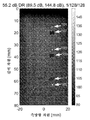
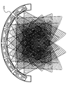
도 1은 전체 합성 전송 개구를 통해 획득된 예시적인 이미지를 도시한다.
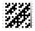
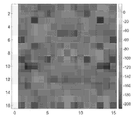
도 2a는 각각의 행에서 전송 벡터들을 갖는 n=16에 대응하는 예시적인 Hadamard 행렬 도면을 도시한다.
도 2b는 도 2a에 도시된 n=16 Hadamard 행렬 행들의 이산 푸리에 변환의 크기에 대한 예시적인 도면을 도시하며, 여기서, DC 값은 각각의 행에서 최좌측에 있다.
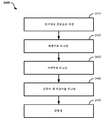
도 3은 개시된 기술에 따른 합성 개구 음향 촬영에서 음향 파형들의 공간 및 시간 인코딩과 디코딩을 위한 한 예시적인 방법의 도면을 도시한다.
도 4는 개시된 기술에 따른 합성 개구 음향 촬영에서 음향 파형들의 공간 및 시간 인코딩을 위한 시스템의 한 예시적인 실시예의 도면을 도시한다.
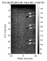
도 5a 및 도 5b는, 각각, 128개 지연들의 128개 세트에 대해 전체 합성 전송 개구 및 지연 인코딩된 합성 전송 개구를 통해 획득된 예시적인 이미지들을 도시한다.
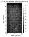
도 6a 및 도 6b는, 각각, 128개 지연들의 16개 세트에 대해 전체 합성 전송 개구 및 지연 인코딩된 합성 전송 개구를 통해 획득된 예시적인 이미지들을 도시한다.
도 7a 및 7b는, 각각, 0 내지 1 파장에 걸친 128개 세트의 지연들에 대해 전체 합성 전송 개구 및 지연 인코딩된 합성 전송 개구를 통해 획득된 예시적인 이미지들을 도시한다.
도 8a 및 도 8b는, 각각, 0 내지 1 파장에 걸친 16개 세트의 지연들에 대해 전체 합성 전송 개구 및 지연 인코딩된 합성 전송 개구를 통해 획득된 예시적인 이미지들을 도시한다.
도 9a는, 16개의, 길이 16 무작위 진폭 및 위상 전송 공간 인코딩 벡터들의 수치적으로 최적화된 세트의 한 예를 도시한다.
도 9b는 도 9a에 대응하는 이산 푸리에 변환의 크기의 한 예를 도시한다.
도 9c는 도 9a에 대응하는 공간 인코딩들의 원형 자기상관(circular autocorrelation)의 한 예를 도시한다.
도 10 및 도 11은, 지연 인코딩만으로 빔형성된, 및 진폭 및 위상 인코딩과 결합된 지연 인코딩으로 빔형성된, 9개의 포인트 표적들의 예시적인 이미지를 도시한다.
도 12는 개시된 기술의 합성 전송 개구 음향 시스템의 한 예시적인 실시예의 블록도를 도시한다.
도 13은 프로브의 180° 곡률을 따라 복수의 전송 위치로부터 합성 전송 개구 빔을 형성하는 복수의 변환기 세그먼트 상의 변환기 어레이들에 의해 생성된 예시적인 복합 초음파 빔들의 도면을 도시한다.
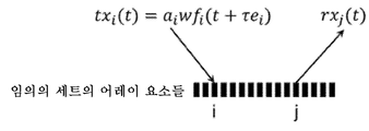
도 14는 공간 및 시간 전송 인코딩된 파형들 및 디코딩 전의 수신 파형들의 수학적 서술에 대응하는 임의의 세트의 변환기 어레이 요소들의 도면을 도시한다.
도 15는 일정한 지연을 갖는 16-요소 어레이에서의 전송의 한 예를 나타내는 변환기 어레이 요소들의 도면을 도시한다.
도 16은 무작위 인코딩된 지연을 갖는 16-요소 어레이에서의 전송의 한 예를 나타내는 변환기 어레이 요소들의 도면을 도시한다.
도 17은 단일 표적 포인트 p에 대한 인코딩, 디코딩 및 빔형성을 위한 지오메트리에 대응하는 임의의 세트의 변환기 어레이 요소들의 도면을 도시한다.
도 18은 파형 인코딩에 이용되는 16개의 상이한 파형을 나타내는 도면을 도시한다.
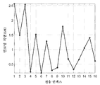
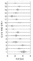
도 19는 지연 인코딩에 대한 16개의 무작위 지연을 나타내는 플롯을 도시한다.
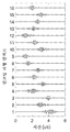
도 20은 도 19에 대응하는 지연 인코딩을 갖는 16개의 상이한 파형을 나타내는 도면을 도시한다.
도 21은 진폭 및 위상 인코딩에 대한 16개의 진폭 및 위상 값들의 예시적인 시퀀스를 나타내는 플롯을 도시한다.
도 22는 도 21의 시퀀스의 원형 자기상관을 나타내는 플롯을 도시한다.
도 23은 도 19에 대응하는 지연 인코딩 및 도 21에 대응하는 진폭 및 위상 인코딩을 갖는 16개의 상이한 파형들을 나타내는 도면을 도시한다.
도 24는 본 기술에 따른 디코딩 방법에 대한 한 예시적인 실시예의 도면을 도시한다.1 shows an exemplary image obtained through the entire composite transmission aperture.
2A shows an exemplary Hadamard matrix diagram corresponding to n=16 with transmission vectors in each row.
FIG. 2B shows an exemplary diagram for the magnitude of the discrete Fourier transform of n=16 Hadamard matrix rows shown in FIG. 2A, where the DC value is at the leftmost in each row.
3 shows a diagram of an exemplary method for spatial and temporal encoding and decoding of acoustic waveforms in composite aperture acoustic imaging according to the disclosed technology.
4 shows a diagram of one exemplary embodiment of a system for spatial and temporal encoding of acoustic waveforms in composite aperture acoustic imaging according to the disclosed technology.
5A and 5B show example images obtained through a full composite transmission aperture and a delay encoded composite transmission aperture for 128 sets of 128 delays, respectively.
6A and 6B show example images obtained through a full composite transmission aperture and a delay encoded composite transmission aperture for 16 sets of 128 delays, respectively.
7A and 7B show example images obtained through a full composite transmission aperture and a delay encoded composite transmission aperture for 128 sets of delays spanning 0 to 1 wavelength, respectively.
8A and 8B show example images obtained through a full composite transmission aperture and a delay encoded composite transmission aperture for 16 sets of delays spanning 0 to 1 wavelength, respectively.
9A shows an example of a numerically optimized set of 16,
9B shows an example of the magnitude of the discrete Fourier transform corresponding to FIG. 9A.
9C shows an example of circular autocorrelation of spatial encodings corresponding to FIG. 9A.
10 and 11 show exemplary images of nine point targets, beamformed with only delay encoding, and beamformed with delay encoding combined with amplitude and phase encoding.
12 shows a block diagram of one exemplary embodiment of a composite transmission aperture acoustic system of the disclosed technology.
13 shows a diagram of exemplary composite ultrasonic beams generated by transducer arrays on a plurality of transducer segments forming a composite transmission aperture beam from a plurality of transmission locations along the 180° curvature of the probe.
FIG. 14 shows a diagram of any set of transducer array elements corresponding to a mathematical description of spatial and temporal transmission encoded waveforms and received waveforms before decoding.
FIG. 15 shows a diagram of transducer array elements representing an example of transmission in a 16-element array with constant delay.
FIG. 16 shows a diagram of converter array elements representing an example of transmission in a 16-element array with randomly encoded delay.
17 shows a diagram of any set of transducer array elements corresponding to geometry for encoding, decoding and beamforming for a single target point p.
18 shows a diagram representing 16 different waveforms used for waveform encoding.
19 shows a plot showing 16 random delays for delay encoding.
20 shows a diagram showing 16 different waveforms with delay encoding corresponding to FIG.
21 shows a plot showing an exemplary sequence of 16 amplitude and phase values for amplitude and phase encoding.
FIG. 22 shows a plot showing circular autocorrelation of the sequence of FIG. 21.
FIG. 23 shows a diagram showing 16 different waveforms with delay encoding corresponding to FIG. 19 and amplitude and phase encoding corresponding to FIG. 21.
24 shows a diagram of an exemplary embodiment of a decoding method according to the present technology.
음향 촬영은, 조직(tissue)을 포함한 생물학적 매체 등의 물리적 탄성 매체 내에서 음향 파형(예를 들어, 펄스)을 방출함으로써 수행될 수 있다. 음향 파형은, (예를 들어, 변환기 요소들의 어레이의) 변환기 요소로부터 관심대상의 표적 체적(VOI; volume of interest)을 향해 전송된다. 종래의 실제 개구 초음파 촬영 시스템에서, 이미지의 품질은 초음파 시스템의 변환기에 의해 생성된 음장(acoustic field)에 직접적으로 의존하고, 이미지는 통상적으로, 한번에 하나의 축 방향 이미지 라인씩 순차적으로 취득된다(즉, 표적 영역 범위의 슬라이스별 스캔). 이것은, 예를 들어 움직이는 표적의 촬영을 포함한, 다양한 실시간 초음파 촬영 응용에서 해로울 수 있는, 촬영 동안의 프레임 레이트에 대한 제한을 설정한다.Acoustic imaging may be performed by emitting acoustic waveforms (eg, pulses) in physical elastic media, such as biological media including tissue. The acoustic waveform is transmitted from the transducer element (eg, of an array of transducer elements) towards a target volume of interest (VOI). In a conventional real aperture ultrasound imaging system, the quality of the image directly depends on the acoustic field generated by the transducer of the ultrasound system, and the image is typically acquired sequentially, one axial image line at a time ( That is, scanning by slice of the target region range). This sets limits on the frame rate during imaging, which can be detrimental to various real-time ultrasound imaging applications, including, for example, imaging of moving targets.
종래의 실제 개구 초음파 촬영에서의 제한을 해결하기 위해, 합성 개구 초음파 촬영을 이용하여 초음파 이미지의 품질을 향상시킬 수 있다. "합성 개구(synthetic aperture)"는, 위상 중심이 특정한 또는 임의의 형상의 알려진 1차원(1D), 2차원(2D), 및/또는 3차원(3D) 경로를 따라 움직이는, VOI를 검사하기 위한 하나 이상의 더 작은 실제의 개구(서브개구)를 연속적으로 이용하여 이미지 취득을 위한 더 큰 유효(비-실제) 개구를 실현하기 위해 구현되는 개념이다. 합성 개구는, 전기-음향 변환기(예를 들어, 변환기 어레이)의 공간적 위치를 연속적인 빔 전송 및/또는 수신 위치들로 기계적으로 변경함으로써, 또는 전기 음향 변환기 어레이 상의 연속적인 빔 전송 및/또는 수신 위치들의 위상 중심을 전자적으로 변경함으로써, 또는 그 둘의 조합에 의해 형성될 수 있다. 합성 개구-기반의 촬영은, 원래, 레이더 시스템에서, 상공으로부터 관심 영역을 스캔하는 항공기로부터 지상의 넓은 지역을 촬영하기 위해 이용되었다. 초음파 촬영에서 합성 개구 포커싱은, 초음파 전송 요소로부터 VOI 위치까지의 기하학적 거리 및 그 위치로부터 다시 초음파 수신 요소까지의 거리에 기초한다. 초음파 촬영에서, 합성 개구의 이용은, 모든 방향으로부터 복수의 전송기 및 수신기 위치들 각각에서 기록된, 귀환 에코(예를 들어, 단안정적(mono-static) 및 쌍안정적(bi-static) 에코)의 수신된 진폭 및 위상 데이터를 분석함으로써 표적 영역 내의 한 포인트 상의 포커싱을 가능케하여, 전체 영역에 대한 정보를 제공한다. 귀환된 에코의 방향은 하나의 수신기 채널만으로 결정될 수 없기 때문에, 많은 수신기 채널들이 이용되어, 채널들의 일부 또는 전부에 걸쳐 처리되는 귀환 에코에 포함된 정보를 결정하여, 궁극적으로 표적 영역의 이미지를 생성하는데 이용되는 정보를 렌더링한다.In order to solve the limitations in the conventional actual aperture ultrasound imaging, it is possible to improve the quality of the ultrasound image using synthetic aperture ultrasound imaging. A “synthetic aperture” is intended to examine a VOI whose phase center moves along a known one-dimensional (1D), two-dimensional (2D), and/or three-dimensional (3D) path of a specific or arbitrary shape. It is a concept implemented to realize a larger effective (non-real) aperture for image acquisition by successively using one or more smaller actual apertures (sub apertures). The synthetic apertures mechanically change the spatial position of the electro-acoustic transducer (eg, transducer array) to successive beam transmission and/or reception locations, or successive beam transmission and/or reception on the electroacoustic transducer array. It can be formed by electronically changing the phase center of the positions, or by a combination of the two. Composite aperture-based imaging was originally used in radar systems to image large areas of the ground from aircraft scanning areas of interest from above. Synthetic aperture focusing in ultrasound imaging is based on the geometric distance from the ultrasound transmitting element to the VOI position and from that position back to the ultrasound receiving element. In ultrasound imaging, the use of synthetic apertures is a method of return echo (eg, mono-static and bi-static echo) recorded at each of a plurality of transmitter and receiver positions from all directions. Analysis of the received amplitude and phase data enables focusing on one point in the target area, providing information about the entire area. Since the direction of the returned echo cannot be determined by only one receiver channel, many receiver channels are used to determine the information contained in the returned echo processed over some or all of the channels, ultimately creating an image of the target area It renders the information used to do it.
전체 합성 전송 개구 촬영의 일부 구현에서, 전체 세트의 전송기들 내의 각각의 전송기는, 순차적으로, 별개로, 이어서, 연속적으로 및 개별적으로 여기될 수 있다. 에코는, 각각의 전송기 공간 위치에 대해 전체 세트의 수신기들 상에서 기록된다. 공간 위치를 공유하거나 공유하지 않을 수 있는 한 세트의 M개의 전송기들 및 N개의 수신기들을 고려하면, 결과적인 초음파 에코의 수는 M x N과 동일하다. 예를 들어, 128-요소 초음파 어레이의 경우, 에코의 총수는 16384와 동일하다. 에코는, 이미지를 포함하는 공간에서 한 세트의 포인트들을 빔형성하기 위해 적용되는 지연-및-합산 빔형성기에 공급되며, 결과 이미지는 공간 해상도에 대한 "황금 표준(gold standard)"으로서 간주된다. 전체 합성 전송 개구의 속성은, 수신 개구와 전송 개구의 콘볼루션(convolution)으로 인해 물리적 개구의 가상 확장과 결합된 전송 및 수신 양쪽 모두 상의 (예를 들어, 변환기 요소에 의해 제공되는) 이용가능한 모든 공간 샘플의 이용과 관련된다. 전송 및 수신 양쪽 모두에 동일한 개구가 이용되는 경우, 유효 개구는 물리적 개구의 크기의 2배이므로, 유효 f-수(f-number) 및 공간 해상도는 2배 감소된다.In some implementations of full composite transmission aperture imaging, each transmitter in the entire set of transmitters can be excited sequentially, separately, then continuously and individually. The echo is recorded on the entire set of receivers for each transmitter spatial location. Considering a set of M transmitters and N receivers that may or may not share a spatial location, the resulting number of ultrasonic echoes is equal to M x N. For example, for a 128-element ultrasonic array, the total number of echoes is equal to 16384. The echo is fed to a delay-and-sum beamformer that is applied to beamform a set of points in the space containing the image, and the resulting image is considered a "gold standard" for spatial resolution. The properties of the overall composite transmission aperture are all available on both the transmission and reception (eg, provided by the transducer element) combined with the virtual extension of the physical aperture due to the convolution of the reception aperture and the transmission aperture. Related to the use of spatial samples. If the same aperture is used for both transmission and reception, the effective aperture is twice the size of the physical aperture, so the effective f-number and spatial resolution are reduced by 2 times.
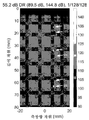
도 1은 전체 합성 전송 개구를 통해 획득된 예시적인 이미지(100)를 도시한다. Verasonics 초음파 촬영 시스템에 접속된 5MHz에서 동작하는 Philips/ATL L7-4 선형 어레이를 이용하여 생성된, 이 예시적인 이미지는, CIRS Model 044 초음파 팬텀(ultrasound phantom)이고 전체 합성 전송 개구 빔형성을 통해 획득되었으며, 55.2 dB의 동적 범위를 가진다. 이미지는, 각각, 15mm, 35mm 및 65mm 깊이 부근에서 볼 수 있는 3개의 100 마이크로미터 나일론 와이어 표적(101, 103, 105로 라벨링됨)을 도시한다. 마찬가지로, 이미지는 각각 20mm, 40mm, 60mm 및 80mm 깊이 부근에서 볼 수 있는 4개의 무반향 표적(107, 109, 111로 라벨링되고 하나는 도시되지 않음)을 도시한다. 공간 해상도는, 약 30mm를 초과하는 고도 빔(elevation beam)의 디포커싱과 결합된 깊이와 함께 선형으로 증가하는 f-수로 인한 증가하는 깊이에 따라 악화된다.1 shows an
전체 합성 전송 개구 촬영을 위해 주어진 이미지 포인트에 대응하는 공간 샘플들(예를 들어, 변환기 요소들)의 대부분은 중복될 수 있거나 및/또는 대체로 유사한 정보를 포함할 수 있다는 것이 합성 개구 촬영 분야의 통상의 기술자들에게 널리 알려져 있다. 사실상, 이러한 중복성은, 공간 해상도에서의 희생에도 불구하고, SNR 및 속도 취득을 개선하기 위해 합성 전송 개구가 2개 이상의 인접한 요소들의 감소된 세트의 서브개구들을 포함할 때 종종 활용된다. 추가로, 감소된-중복성 공간 샘플링 방식은 잘 알려져 있고, 공간 영역에서 선형 콘볼루션을 통해 전송 및 수신 개구, 및 대응하는 전송 수신 개구 응답의 k-공간 표현들의 곱을 이용하여 쉽게 공식화된다.It is common in the field of composite aperture imaging that most of the spatial samples (eg, transducer elements) corresponding to a given image point for full composite transmission aperture imaging may be redundant and/or generally contain similar information. It is widely known to the technicians. In fact, this redundancy is often utilized when the composite transmission aperture includes a reduced set of sub-apertures of two or more adjacent elements to improve SNR and speed acquisition, despite sacrifices in spatial resolution. Additionally, the reduced-duplication spatial sampling scheme is well known and is easily formulated using the product of the k-space representations of the transmit and receive apertures and the corresponding transmit and receive aperture response through linear convolution in the spatial domain.
합성 전송 개구 촬영에서의 중요한 중복성은 음향 상호성(acoustic reciprocity)의 원리에 기초한다, 예를 들어, 요소 i에서의 전송 및 요소 j에서의 수신으로부터 발생하는 에코는 요소 j에서의 전송 및 요소 i에서의 수신으로부터 발생하는 에코와 실질적으로 동일하며, 이에 의해, 전송기 및 수신기 조합의 대략 절반이 동일한 것으로 가정된다. 예를 들어, Tx, Rx 조합(i,j)에 대한 지식으로, Tx, Rx 조합(j,i)이 복구, 추정 및/또는 교체될 수 있다. 더욱이, N2개의 에코 샘플들, 즉, 주어진 이미지 포인트에 대한 모든 가능한 전송기 및 수신기 조합들 중 2N-1개만이 거의 균등한 이미지를 형성하는데 필요하다는 것이 잘 알려져 있다. 예를 들어, 모든 Tx, Rx 조합(i,j)으로부터, 완전-공간적으로 샘플링된 이미지 형성에 요구되는 2N-1개의 에코 샘플은, 총 2N-1개의 에코 샘플에 대해, (N개의 에코 샘플에 대응하는) i=j인 조합들과 (N-1개의 에코 샘플에 대응하는) i=j+1인 조합들을 포함한다.Significant redundancy in composite transmission aperture imaging is based on the principle of acoustic reciprocity, e.g. echoes resulting from transmission at element i and reception at element j are transmitted at element j and at element i It is assumed to be substantially the same as the echo resulting from the reception of, whereby approximately half of the transmitter and receiver combinations are identical. For example, with knowledge of the Tx, Rx combination (i,j), the Tx, Rx combination (j,i) can be recovered, estimated and/or replaced. Moreover, it is well known that only N 2 echo samples, i.e. 2N-1 of all possible transmitter and receiver combinations for a given image point, are needed to form an almost uniform image. For example, from all Tx, Rx combinations (i,j), the 2N-1 echo samples required for the formation of a fully-spatially sampled image, for a total of 2N-1 echo samples, (N echo samples I=j) and i=j+1 (corresponding to N-1 echo samples).
그러나, 합성 전송 개구 촬영에서 중복성을 이용하기 위한 공지된 기술은 많은 수의 전송(N)으로 인해 느린 취득 속도를 초래한다. 따라서, 합성 전송 개구 촬영에서 중복성을 활용하여 N개의 전송으로부터 N개보다 상당히 적은 전송으로 취득을 가속화할 기회가 존재한다.However, known techniques for utilizing redundancy in composite transmission aperture imaging result in slow acquisition rates due to the large number of transmissions (N). Therefore, there is an opportunity to accelerate acquisition from N transmissions to considerably fewer than N transmissions by utilizing redundancy in composite transmission aperture imaging.
또한, 한 번에 하나의 요소에서 전송하는 프로세스는, 사운드 속도와 관심 깊이에 의해 결정되는, 왕복 시간에 의해 제한된다. 또한, 한 번에 하나의 요소에서의 전송은, 평면파 전송, 가상 소스 전송 및 서브개구 전송을 포함한 그러니 이것으로 제한되지 않는, 하나보다 많은 요소를 이용한 포커싱된 전송 또는 다른 조율된 전송 모드에 비해 전송되는 에너지의 양을 크게 제한한다. 따라서, 전체 합성 전송 개구 촬영은 불량한 SNR 및 침투 깊이를 겪는다.Also, the process of transmitting from one element at a time is limited by the round-trip time, which is determined by the sound speed and depth of interest. In addition, the transmission in one element at a time, compared to other coordinated transmission modes or focused transmission using more than one element, including but not limited to, plane wave transmission, virtual source transmission and sub-aperture transmission. It greatly limits the amount of energy that is produced. Thus, the overall composite transmission aperture imaging suffers from poor SNR and penetration depth.
코딩된 개구 전송은, 전송 개구를 인코딩하는 직교 벡터들의 세트들을 이용함으로써 전송되는 에너지의 양을 크게 개선시킨다. Hadamard 행렬은, 2상 값들, -1 및 1만으로 구성된 한 세트의 선형 독립 벡터들에 기초하여 코딩된 개구 전송에서 이용될 수 있다. 모든 Hadamard 행렬들은 차원이 n×n인 정사각형이고, 여기서 n은 세트 2k에서 나올 수 있으며, k는 음이 아닌 정수이다. n의 많은 다른 값들도 Hadamard 행렬 속성을 갖는다고 역시 알려져 있다. H를 차수 n인 Hadamard 행렬이라고 하자. H의 전치행렬(transpose)은 다음과 같이 그 역과 밀접한 관련이 있다:Coded aperture transmission greatly improves the amount of energy transmitted by using sets of orthogonal vectors encoding the transmission aperture. The Hadamard matrix can be used in coded aperture transmission based on a set of linear independent vectors composed of only two-phase values, -1 and 1. All Hadamard matrices are squares of dimension n×n, where n can come from set 2k and k is a nonnegative integer. It is also known that many other values of n also have Hadamard matrix properties. Let H be the Hadamard matrix of order n. H's transpose is closely related to the inverse:
![]()
![]()
여기서 In은 n×n 항등 행렬이고 HT는 H의 전치행렬이다. 수학식 (1)은, H의 행과 열이 모두 실수 필드에 걸쳐 직교 벡터이며 각각의 벡터의 길이 ![]()
![]()
![]()
![]()
전형적으로, 변환기 어레이는 쌍극 전송기 (-1,1)의 경우에 Hadamard 행렬의 직교 벡터를 이용하여 여기된다; 또는, 변환기 어레이는, 단극 2진 전송기 (0,1)의 경우, 관련된 2진 버전의 Hadamard 행렬, 예를 들어, S-행렬(산란 행렬)를 이용하여 여기될 수 있다. S-행렬은 Hadamard 행렬보다 약간 열등하게 하는 작은 제한을 갖지만, 일부 응용에서는, 예를 들어, 전송기 출력이 반전될 수 없는 때에는 유용하다.Typically, the array of transducers is excited using the orthogonal vector of the Hadamard matrix in the case of the bipolar transmitter (-1,1); Alternatively, the converter array can be excited using a binary version of the Hadamard matrix, eg, an S-matrix (scattering matrix), in the case of a unipolar binary transmitter (0,1). The S-matrix has a small limitation that makes it slightly inferior to the Hadamard matrix, but is useful in some applications, for example, when the transmitter output cannot be inverted.
Hadamard 행렬은 제로-지연 공간 위상 인코딩 방식을 가능케한다. 따라서, 공간 인코딩 및 디코딩 프로세스는, 직교 벡터들의 전송들 사이에 작은 지연이 있다고 가정한다. 다시 말해서, 전송들 사이에 어떠한 움직임 또는 변화도 발생하지 않는다고 가정하고, 전송들 사이의 유일한 변수는 전송되는 H의 특정한 행(또는 열)이라고 가정하고, 음향 에코가 디코딩된다. 디코딩은 빔형성기에서의 지연-및-합산 동작과는 독립적이다. 이 방법은 또한, 각각의 직교 벡터의 요소들은, 각각의 직교 벡터를 포함하는 전송들 사이에 지연이 없도록 하는 이상적인 타이밍으로 동시에 전송된다고 가정한다. 따라서, Hadamard 행렬의 직교 벡터들에 대응하는 음향 에코들의 세트는, 행들 또는 열들 사이 또는 Hadamard 행렬의 임의의 요소들 사이의 제로 지연 또는 위상을 가정하여, 동시에 디코딩된다.The Hadamard matrix enables a zero-delay spatial phase encoding scheme. Thus, the spatial encoding and decoding process assumes there is a small delay between transmissions of orthogonal vectors. In other words, it is assumed that no movement or change occurs between the transmissions, and that the only variable between the transmissions is a specific row (or column) of H being transmitted, and the acoustic echo is decoded. Decoding is independent of the delay-and-add operation in the beamformer. The method also assumes that the elements of each orthogonal vector are transmitted at the same time with an ideal timing such that there is no delay between transmissions containing each orthogonal vector. Thus, the set of acoustic echoes corresponding to orthogonal vectors of the Hadamard matrix are decoded simultaneously, assuming zero delay or phase between rows or columns or between any elements of the Hadamard matrix.
Hadamard 인코딩 방식이 전체 합성 전송 개구 전송과 공유하는 한 가지 주요 단점은, n개의 전송을 요구하며, 이것은, 진정한 리프레시 레이트를, 펄스 반복 주파수(PRF; pulse repetition frequency)를 n으로 나눈 값으로 제한한다는 것이다. 마지막 전송된 Hadamard 직교 벡터에 대응하는 에코 세트가 빔형성 전에 교체될 때 피상 리프레시 레이트는 PRF와 동일하다; 그러나, 움직임의 완전하고 적절한 샘플링은 PRF/n에 의해 제한되므로, 1 파장의 PRF/n배 정도의 속도들에 대해 움직임 흐림(motion blur) 아티팩트들을 초래한다. Hadamard 공간 인코딩의 또 다른 단점은 특정한 크기의 제곱 행렬로 제한된다는 것이다. Hadamard 공간 인코딩의 또 다른 단점은 전체 세트의 취득 시간을 감소시키기 위해 시간 코딩을 이용하지 않는다는 것이다.One major drawback that the Hadamard encoding scheme shares with the overall composite transmission aperture transmission, requires n transmissions, which limits the true refresh rate to the value of pulse repetition frequency (PRF) divided by n. will be. The apparent refresh rate is the same as the PRF when the echo set corresponding to the last transmitted Hadamard orthogonal vector is replaced before beamforming; However, complete and proper sampling of motion is limited by PRF/n, resulting in motion blur artifacts for speeds on the order of PRF/n times one wavelength. Another disadvantage of Hadamard spatial encoding is that it is limited to a square matrix of a certain size. Another disadvantage of Hadamard spatial encoding is that it does not use time coding to reduce the acquisition time of the entire set.
Hadamard 공간 인코딩은 또한, 추가적인 SNR 개선을 위해, 상보적인 코딩된 파형, 예를 들어 Golay 코딩된 파형의 이용으로 확장되었다. 그럼에도 불구하고, 기본 동작 및 연관된 제한은 주로 Hadamard 공간 인코딩의 것을 따른다.Hadamard spatial encoding has also been extended with the use of complementary coded waveforms, for example Golay coded waveforms, for further SNR improvement. Nevertheless, the basic behavior and associated limitations mainly follow that of Hadamard spatial encoding.
Hadamard 공간 인코딩은 또한, 상당히 큰 디코딩 복잡도를 가짐에도, 위상 인코딩 대신에 지연 인코딩된 전송의 이용으로 확장되었다. 그럼에도 불구하고, 기본 동작 및 연관된 제한은 주로 Hadamard 공간 인코딩의 것을 따른다.Hadamard spatial encoding has also been extended to the use of delay-encoded transmission instead of phase encoding, although it has a fairly large decoding complexity. Nevertheless, the basic behavior and associated limitations mainly follow that of Hadamard spatial encoding.
최상의 가능한 촬영 속도 및 해상도를 달성하기 위해, 시간 변화의 영향, 예를 들어 조직 움직임을 완화하기 위하여 모든 공간 주파수가 동시에 또는 거의 동시에 여기되어야만 한다. Hadamard 공간 인코딩은 모든 공간 주파수를 여기시키지만, 동시에 모두 여기되지는 않는다. 전체 세트의 직교 벡터들의 선형 조합이 고려될 때만(예를 들어, 수학식 (1) 참조) 모든 공간 주파수가 여기된다. 이것은, Hadamard 행렬의 푸리에 변환이, 도 2a에 도시된 Hadamard 행렬에 대해 도 2b에 도시된 바와 같이 각각의 전송 벡터에 대해 일정한 값이 아니라는 사실에 의해 입증된다 - 전송 벡터는 각각의 행에 있다.In order to achieve the best possible shooting speed and resolution, all spatial frequencies must be excited simultaneously or almost simultaneously in order to alleviate the effects of temporal changes, eg tissue movement. Hadamard spatial encoding excites all spatial frequencies, but not all at the same time. All spatial frequencies are excited only when a linear combination of the entire set of orthogonal vectors is considered (see, for example, equation (1)). This is evidenced by the fact that the Fourier transform of the Hadamard matrix is not a constant value for each transmission vector as shown in Figure 2b for the Hadamard matrix shown in Figure 2a-the transmission vector is in each row.
도 2a 및 도 2b는 각각의 행에서 전송 벡터들을 갖는 n=16에 대응하는 예시적인 Hadamard 행렬의 도면(도 2a) 및 DC 값이 각각의 행에서 최좌측에 있는 도 2a로부터의 n=16 Hadamard 행렬 행들에 대한 이산 푸리에 변환의 도면(도 2b)을 도시한다. 예를 들어, 모든 공간 주파수를 복구하기 위해 전체 세트가 전송되어야 하기 때문에, Hadamard 공간 인코딩은 움직임 아티팩트들에 매우 취약하다.2A and 2B are diagrams of an exemplary Hadamard matrix corresponding to n=16 with transmission vectors in each row (FIG. 2A) and n=16 Hadamard from FIG. 2A with a DC value leftmost in each row. Shows a diagram of the discrete Fourier transform for the matrix rows (FIG. 2B). Hadamard spatial encoding is very vulnerable to motion artifacts, for example, because the entire set must be transmitted to recover all spatial frequencies.
움직임에 덜 취약한 인코딩 전략은, 각각의 전송 벡터에 대해 모든 공간 주파수를 동등하게 여기시키는 공간 인코딩 방식을 이용할 것이다. 모든 공간 주파수가 동시에 여기된다는 추가적인 제약과 함께, 수학식 (1)과 유사한 완벽한 선형 분리를 갖는 다른 공간 인코딩 방식이 실현될 수 있다. 이러한 전략은 N개 전송의 제한을 여전히 받을 수 있지만, 공간 샘플링 정보의 중복성은 움직임에 대한 더 적은 취약성을 보장할 것이다.An encoding strategy that is less susceptible to motion will use a spatial encoding scheme that excites all spatial frequencies equally for each transmission vector. With the additional constraint that all spatial frequencies are excited simultaneously, other spatial encoding schemes with perfect linear separation similar to equation (1) can be realized. This strategy may still be limited by N transmissions, but the redundancy of spatial sampling information will ensure less vulnerability to movement.
더 적은 신호 전송들로 의료 촬영을 위한 공간 및 콘트라스트 해상도를 달성하기 위해 전체 합성 전송 개구 촬영에서 전송의 공간 및 시간 인코딩을 위한 기술, 시스템 및 디바이스가 개시된다.Techniques, systems and devices for spatial and temporal encoding of transmissions in full composite transmission aperture imaging to achieve spatial and contrast resolution for medical imaging with fewer signal transmissions are disclosed.
일부 예시적인 실시예에서, 프로브 디바이스는, 변환기 요소들의 어레이를 포함하는 하나 이상의 변환기 세그먼트, 및 변환기 요소들의 어레이와 통신하여 파형들을 전송할 어레이의 변환기 요소들의 제1 서브세트를 선택하고, 귀환된 파형들을 수신할 어레이의 변환기 요소들의 제2 서브세트를 선택하는 프로브 제어기를 포함하고, 여기서, 변환기 요소들의 제1 서브세트는 생물학적 대상 내의 표적 체적을 향해 파형들을 전송하도록 배열되고, 변환기 요소들의 제2 서브세트는 표적 체적의 적어도 일부로부터 귀환하는 귀환된 파형들을 수신하도록 배열된다. 프로브 디바이스는, 미리결정된 (i) 고유한 세트의 파형들, (ii) 전송 지연 패턴, 및/또는 (iii) 전송 진폭 및 위상 패턴을 포함하는 공간적으로 및 시간적으로 인코딩된 파형들을 표적 체적에 전송하도록 동작가능하고; 따라서, 표적으로부터 귀환된 음향 파형들을 수신한 후, 귀환된 파형들은, 각각의 전송 변환기 요소에 대응하는 파형 성분들을 각각의 수신 변환기 요소 상의 파형들로부터 분리되도록 처리함으로써 전체 합성 전송 개구 취득을 나타내는 한 세트의 파형들을 획득함으로써 디코딩된다.In some demonstrative embodiments, the probe device selects one or more transducer segments comprising an array of transducer elements, and a first subset of transducer elements in the array to transmit waveforms in communication with the array of transducer elements, and the returned waveform And a probe controller that selects a second subset of transducer elements of the array to receive them, wherein the first subset of transducer elements is arranged to transmit waveforms towards a target volume within the biological object, and the second of transducer elements The subset is arranged to receive returned waveforms that return from at least a portion of the target volume. The probe device transmits spatially and temporally encoded waveforms to the target volume, including predetermined (i) unique sets of waveforms, (ii) transmission delay patterns, and/or (iii) transmission amplitude and phase patterns. Operable; Thus, after receiving the acoustic waveforms returned from the target, the returned waveforms represent the overall composite transmission aperture acquisition by processing the waveform components corresponding to each transmission transducer element to be separated from the waveforms on each reception transducer element. It is decoded by acquiring a set of waveforms.
일부 예시적인 실시예에서, 음향 신호 전송을 인코딩하기 위한 방법이 개시된다. 이 방법은, 제1 변환기 요소와 연관된 시간 지연 후, 생물학적 대상 내의 표적 체적을 향해 파형들을 제1 변환기 요소에 의해 전송하는 단계; 제1 변환기 요소와 제2 변환기 요소 사이의 왕복 시간 후에, 표적 체적의 적어도 일부로부터 귀환하는 귀환된 파형들을 제2 변환기 요소에 의해 수신하는 단계; 시간 지연 및 왕복 시간에 기초하여 귀환된 음향 파형들에 기여하는 제1 변환기 요소를 식별하는 단계; 및 생물학적 대상 내의 표적 체적의 이미지를 생성하기 위해 제1 변환기 요소의 식별에 기초하여 귀환된 파형들을 처리하는 단계를 포함한다.In some demonstrative embodiments, a method for encoding acoustic signal transmission is disclosed. The method comprises: after a time delay associated with the first transducer element, transmitting waveforms by the first transducer element towards a target volume in the biological subject; After the round-trip time between the first transducer element and the second transducer element, receiving the returned waveforms from at least a portion of the target volume by the second transducer element; Identifying a first transducer element contributing to the returned acoustic waveforms based on the time delay and round trip time; And processing the returned waveforms based on the identification of the first transducer element to create an image of the target volume within the biological object.
도 3은 개시된 기술에 따른 합성 개구 음향 촬영에서 음향 파형들의 공간 및 시간 인코딩을 위한 방법(200)의 한 예시적인 실시예의 도면을 도시한다. 이 방법(200)은, 표적 체적을 향한 전송을 위한 한 세트의 공간적으로 및 시간적으로 인코딩된 음향 파형들을 생성하는 프로세스(210)를 포함하고, 여기서 인코딩은, (i) 고유한 인코딩된 파형 세트, (ii) 표적 체적에 전송되는 파형 세트 중의 파형들의 전송 지연을 위한 패턴, 및/또는 (iii) 표적 체적에 전송될 파형 세트의 전송 진폭 및 위상 패턴 중 하나 이상을 생성하는 것을 포함한다. 이 방법(200)은, 음향 프로브 디바이스의 하나 이상의 변환기 세그먼트에 대한 변환기 요소들의 어레이 상에 형성된 공간적으로 샘플링된 개구 상에서 표적 체적을 향해 파형들을 코히어런트 전송(coherently transmit)하는 프로세스(220)를 포함하고, 여기서 각각의 변환기 요소는 인덱싱된다(예를 들어, 1, 2, … i). 이 방법(200)은, 공간적으로 샘플링된 개구 상에서, 전송된 인코딩된 음향 신호에 기초하는 귀환된 음향 파형들을 수신하는 프로세스(230)를 포함하고, 여기서 각각의 변환기 요소는 j 인덱싱된다(예를 들어, 1, 2… j). 이 방법(200)은, 표적 체적의 한 세트의 이미지 포인트들에 대한 j번째 수신 상의 i번째 전송을 분리하기 위해 귀환된 (인코딩된) 음향 파형들을 디코딩하는 프로세스(240)를 포함한다. 디코딩 프로세스(240)의 일부 예시적인 구현은, 도 24와 관련하여 후술되는 방법(240)을 포함한다. 이 방법(200)은, 표적 체적의 이미지 포인트들의 세트 중의 각각의 이미지 포인트에 대해 분리된 에코 샘플들을 빔형성하고, 표적 체적의 빔형성된 이미지를 형성하도록 처리될 수 있는 데이터 세트를 생성하는 프로세스(250)를 포함한다.FIG. 3 shows a diagram of one exemplary embodiment of a
이 방법(200)의 일부 구현에서, 프로세스(210)는, 전송을 위한 한 세트의 인코딩된 파형들을 생성하는 단계를 포함한다. 이러한 구현에서, 이들 인코딩된 파형들은, 특정한 속성을 갖는 코드, 즉, 숫자 세트로부터 도출된다. 예를 들어, 인코딩된 파형의 유용한 속성은, 디코딩될 때 범위 로브(range lobe)가 작거나 0에 가깝고 디코딩된 파형의 진폭이 인코딩된 파형보다 높은 것이다. 디코딩 프로세스는, 이 예의 경우, 범위 압축 또는 정합된 필터링을 포함할 수 있다. 2개 이상의 인코딩된 파형의 또 다른 예시적인 속성은 2개 이상의 인코딩된 파형이 직교하는 것이다. 예를 들어, 한 세트의 2개의 인코딩된 파형들이 주어지면, 제1 파형이 제2 파형에 대한 디코딩 방법으로 디코딩된다면, 출력은 이상적으로 0이다. 마찬가지로, 제2 파형이 제1 파형에 대한 디코딩 방법으로 디코딩된다면, 출력은 이상적으로 0이다. 마찬가지로, 직교성은 선형성 및 시불변성을 따르고, 예를 들어, 스케일링, 가산, 감산 및/또는 지연을 포함하는 동작들을 통해 제1 및 제2 파형의 선형 조합으로부터 형성된 복합 파형이 디코딩될 수 있다. 바람직하게는, 프로세스(201)에 의해 생성된 고유한 세트의 인코딩된 파형들은, 이상적으로 압축적이고 이상적으로 직교하는 2개 이상의 인코딩된 파형들을 포함한다. 이들 파형들의 세트는 주파수-코딩된 및/또는 위상-코딩된 파형들을 포함할 수 있지만, 이러한 주파수-코딩 및/또는 위상 코딩은 선택사항이며, 고유한 세트의 인코딩된 파형들은 범위 압축 및 직교성의 속성들을 동시에 충족시키는 임의의 파형을 포함할 수 있다. 실제로, 2개보다 많은 파형에 대해 동시에 및 이상적으로 양쪽 속성을 모두 달성하기는 어렵기 때문에, 절충이 이루어져야 한다. 범위 압축 및/또는 직교성의 비이상적인 성질은, 공간 지연 및/또는 공간 진폭 및 위상 인코딩을 포함함으로써 감소될 수 있으며, 이들 기술들은 프로세스(210)의 구현에 포함될 수 있다.In some implementations of this
도 4는 전체 합성 전송 개구 음향 촬영에서 음향 파형들의 공간 및 시간 인코딩을 위한 시스템(300)의 한 예시적인 실시예의 도면을 도시한다. 시스템(300)은, 전송 파형을 공간적으로 및 시간적으로 인코딩하고, 귀환된 인코딩된 파형들을 디코딩하여 빔형성된 이미지를 생성하기 위한 방법(200)을 구현하도록 동작가능하다. 일부 구현에서, 시스템(300)은, 확산 스펙트럼, 넓은 순간 대역폭, 코히어런트, 의사-랜덤 잡음 특성, 및 코딩을 포함하는 복합 음향 파형의 형태로 공간적으로 및 시간적으로 인코딩된 파형들을 생성하도록 동작가능하다. 예시적인 시스템(300)은, 개시된 기술에 따른 많은 시스템 설계 중 하나를 도시한다.FIG. 4 shows a diagram of one exemplary embodiment of a
도 4의 예에 도시된 바와 같이, 시스템(300)은, 합성 개구 음향 파형(SAAW; synthetic aperture acoustic waveform) 처리 디바이스(310) 및 SAAW 처리 디바이스(310)와 통신하는 음향 프로브 디바이스(320)를 포함한다. 시스템(300)은 SAAW 처리 디바이스(310)와 통신하는 컴퓨터(330)를 포함하고, 컴퓨터(330)는, 처리 유닛(미도시), 디스플레이(331), 및 시스템(300)의 동작을 위해 데이터 입력을 수신하고 및 데이터 출력을 디스플레이하기 위한 사용자 인터페이스 모듈(333)을 포함한다. 컴퓨터(330)는, 개인용 컴퓨터(PC), 랩탑, 태블릿, 및 모바일 통신 디바이스 아키텍쳐 등의 다양한 데이터 처리 아키텍쳐들 중 하나로서 구현될 수 있다. 일부 예에서, 사용자 인터페이스(333)는, 다양한 유형의 키보드, 마우스, 음성 명령, 터치 패드 및 두뇌-머신 인터페이스 장치들을 포함하는 많은 적절한 인터페이스를 포함할 수 있다.As shown in the example of FIG. 4,
SAAW 처리 디바이스(310)는, 데이터 처리 유닛을 포함하는 시스템 제어기(313)를 포함한다. 시스템 제어기(313)의 데이터 처리 유닛은, 데이터를 처리하는 프로세서, 프로세서와 통신하며 데이터를 저장하는 메모리, 및 프로세서 및/또는 메모리를, 전자 유닛의 다른 모듈, 유닛 또는 디바이스에 또는 외부 디바이스에 인터페이싱하는 입력/출력 유닛(I/O)을 포함한다. 예를 들어, 프로세서는, 중앙 처리 유닛(CPU), 마이크로제어기 유닛(MCU), 또는 기타의 프로세서 유닛을 포함할 수 있다. 예를 들어, 프로세서는, ASIC(application-specific integrated circuit), FPGA(field-programmable gate array), DSP(digital signal processor), AsAP(asynchronous array of simple processor), 및 기타 유형의 데이터 처리 아키텍쳐를 포함할 수 있다. 예를 들어, 메모리는, 프로세서에 의해 실행될 때, 예를 들어 정보, 명령 및/또는 데이터 수신, 정보 및 데이터 처리, 음향 프로브 디바이스(320) 및/또는 컴퓨터(330)로의 정보/데이터의 전송 또는 제공 등의, 다양한 동작을 수행하도록 데이터 처리 유닛을 구성하는 프로세서-실행가능한 코드를 포함하고 저장할 수 있다. 일부 구현에서, 시스템 제어기(313)의 데이터 처리 유닛(및/또는 컴퓨터(330)의 처리 유닛)은, 하나 이상의 원격 계산 처리 디바이스(예를 들어, 클라우드 내의 서버)를 포함하는 ('클라우드'라고 지칭되는) 인터넷을 통해 액세스가능한 컴퓨터 시스템 또는 통신 네트워크에 원시 및/또는 처리된 데이터를 전송할 수 있다. 데이터 처리 유닛의 다양한 기능을 지원하기 위해, 메모리는, 명령어, 소프트웨어, 값, 이미지, 및 프로세서에 의해 처리되거나 참조되는 기타의 데이터 등의, 정보 및 데이터를 저장할 수 있다. 예를 들어, 다양한 유형의 RAM(Random Access Memory) 디바이스, ROM(Read Only Memory) 디바이스, 플래시 메모리 디바이스, 및 기타 적절한 저장 매체가 메모리의 저장 기능을 구현하는데 이용될 수 있다. 시스템 제어기(313)의 데이터 처리 유닛(및/또는 컴퓨터(330)의 처리 유닛)의 I/O는, 예를 들어, Bluetooth, Bluetooth low energy, Zigbee, IEEE 802.11, WLAN(Wireless Local Area Network), WPAN(Wireless Personal Area Network), WWAN(Wireless Wide Area Network), WiMAX, IEEE 802.16 (Worldwide Interoperability for Microwave Access (WiMAX)), 3G/4G/LTE 셀룰러 통신 방법, NFC(Near Field Communication), 및 병렬 인터페이스를 포함한 그러나 이것으로 제한되지 않는, 무선 전송기/수신기(Tx/Rx) 유닛을 통해, 다른 디바이스와의 데이터 처리 유닛의 통신에 이용될 수 있는, 전형적인 데이터 통신 표준과 호환되는 다양한 유형의 유선 또는 무선 인터페이스를 이용하기 위해 데이터 처리 유닛을 무선 통신 유닛과 인터페이싱할 수 있다. 데이터 처리 유닛의 I/O는 또한, 다른 외부 인터페이스, 데이터 저장 소스, 및/또는 시각 또는 오디오 디스플레이 디바이스 등과 인터페이싱하여, 프로세서에 의해 처리되거나, 메모리에 저장되거나, 출력 유닛 또는 외부 디바이스 상에 표시될 수 있는 데이터 및 정보를 회수 및 전송할 수 있다.The SAAW processing device 310 includes a
SAAW 처리 디바이스(310)는, 개시된 공간적으로 및 시간적으로 인코딩된 합성 음향 전송 개구 기술에 따라 하나 이상의 디지털 파형을 생성하기 위해 시스템 제어기(313)에 의해 제어될 수 있는 파형 생성기(311)를 포함한다. 파형 생성기(311)는, 음향 프로브 디바이스가, 예를 들어 공간적으로 및 시간적으로 인코딩된 복합 음향 파형을 포함한 음향 파형으로서 변환하는 하나 이상의 디지털 파형에 대응하는 아날로그 전자 신호를 생성하는, 파형 합성기들 및 빔 제어기들의 어레이를 포함한다. 파형 생성기(311)는, 함수 생성기 또는 임의의 파형 생성기(AWG; arbitrary waveform generator)를 포함할 수 있다. 예를 들어, 파형 생성기(311)는, 파형 합성기 및 빔 제어기가 개개의 아날로그 파형 및/또는 복합 아날로그 파형으로서 합성하기 위한 임의의 디지털 파형을 생성하는 AWG로서 구성될 수 있다. 일부 구현에서, 파형 생성기(311)는, 디지털 파형의 생성에 이용되는 미리 저장된 파형 및 계수 데이터 및 정보를 저장할 수 있는 메모리 유닛을 포함할 수 있다.SAAW processing device 310 includes a
일부 구현에서, 파형 생성기(311)의 파형 합성기 및 빔 제어기는 I개의 어레이 요소를 포함한다. 한 예에서, 파형 합성기 및 빔 제어기는, I개의 어레이 파형 합성기들의 각각의 라인 상에 적어도 하나의 파형 합성기 요소를 포함하도록 구성될 수 있다. 또 다른 예에서, 파형 합성기 및 빔 제어기는, I개의 어레이 빔 제어기의 각각의 라인 상에 적어도 하나의 빔 제어기 요소를 포함할 수 있다. 또 다른 예에서, 파형 합성기 및 빔 제어기는, I개의 어레이 파형 합성기들 및 빔 제어기들의 각각의 라인 상에 적어도 하나의 파형 합성기 요소 및 빔 제어기 요소를 포함할 수 있다. 파형 합성기 및 빔 제어기는, 전자 신호, 예를 들어 무선 주파수(RF) 파형의 생성을 위한 위상-고정 루프 시스템을 포함할 수 있다. 예시적인 RF 파형은, 파형 합성기 및 빔 제어기의 어레이 요소들에서 생성된 개개의 파형으로부터 파형 합성기 및 빔 제어기에 의해 합성될 수 있다, 예를 들어 하나의 개개 RF 파형은, 파형 합성기 및 빔 제어기의 다른 어레이 요소들에 의해 생성된 다른 모든 개개의 파형과 실질적으로 동시에 하나의 어레이 요소에서 생성될 수 있다. 각각의 개개 직교 RF 파형은 주파수 성분 또는 '칩'이라고도 하는 특정한 주파수 대역에 대해 정의될 수 있고, 각각의 개개 직교 파형의 파형 속성은, 칩에 대응하는 적어도 하나의 진폭 값 및 적어도 하나의 위상 값을 포함할 수 있는 파형 생성기(311)에 의해 결정될 수 있다. 파형 생성기(311)는 명령을 내리고, 파형 합성기 및 빔 제어기에 의해 복합 RF 파형을 형성하기 위해 함께 결합될 수 있는 개개의 직교 RF 파형의 생성을 위해, 각각의 개개 직교 파형의 속성에 관한 정보를 포함하는 파형 데이터를 파형 합성기 및 빔 제어기에 전송할 수 있다.In some implementations, the waveform synthesizer and beam controller of
일부 실시예에서, SAAW 처리 디바이스(310)는, 파형 생성기(311)에서 생성된 발생된 파형, 예를 들어 개개의 직교 RF 파형 및/또는 파형 합성기 및 빔 제어기에 의해 생성된 복합 RF 파형을 수정하는 증폭기(317)를 포함한다. 예를 들어, 증폭기(317)는, 이득의 증폭 및/또는 파형의 위상 시프팅을 위해 각각 동작가능한 I개의 증폭기들의 어레이를 포함할 수 있다. 일부 예에서, 증폭기들의 어레이는 선형 증폭기로서 구성된다. 증폭기(317)가 SAAW 처리 디바이스(310)의 일부로서 도시되어 있지만, 증폭기(317)는, 또한 또는 대안으로서, 음향 프로브 디바이스(320)에 포함될 수 있다.In some embodiments, the SAAW processing device 310 modifies the generated waveform generated by the
일부 실시예에서, 시스템 제어기(313)는, 예를 들어 제어 버스를 통한 접속을 통해, 시스템(300)의 모듈들의 일부 또는 전부를 제어할 수 있다. 일부 실시예들에서, 시스템 제어기(313)는, 시간 동기화를 위한 마스터 클록을 포함한다. 예를 들어, 마스터 클록은 시스템 제어기(313)와 인터페이싱할 수 있고 시스템(300)의 다른 모듈들은 서로와의 동작을 동기화한다. 다양한 구현에서, 예를 들어, SAAW 처리 디바이스(310)는, 방법(200)의 프로세스들(210, 220, 230, 240 및/또는 250)을 구현하도록 동작가능하다. 다양한 구현에서, 예를 들어, 음향 프로브 디바이스(320)는, SAAW 처리 디바이스(310)와 연계하여 방법(200)의 프로세스들(220 및/또는 230)을 구현하도록 동작가능하다.In some embodiments,
음향 프로브 디바이스(320)는, 변환기 요소들의 어레이를 포함할 수 있는 하나 이상의 변환기 세그먼트를 포함한다. 음향 프로브 디바이스(320)는, 하나 이상의 변환기 세그먼트와 통신하며(예를 들어, 변환기 요소들의 어레이와 통신하는) 파형을 전송할 어레이의 변환기 요소들의 제1 서브세트를 선택하고 귀환된 파형들을 수신할 어레이의 변환기 요소들의 제2 서브세트를 선택하는 프로브 제어기를 포함한다. 일부 구현에서, 변환기 요소들의 제1 서브세트는 생물학적 대상(예를 들어, 살아있는 유기체) 내의 표적 체적을 향해 파형들을 전송하도록 배열되고, 변환기 요소들의 제2 서브세트는 표적 체적의 적어도 일부로부터 귀환하는 귀환된 파형들을 수신하도록 배열되며, 파형들은, 귀환된 파형들 각각이 구별가능하도록 미리결정된 전송 지연 패턴에 따라 전송된다.The acoustic probe device 320 includes one or more transducer segments, which may include an array of transducer elements. The acoustic probe device 320 communicates with one or more transducer segments (eg, in communication with an array of transducer elements) and selects a first subset of transducer elements of the array to transmit waveforms to and receives the returned waveforms And a probe controller for selecting a second subset of the transducer elements of the. In some implementations, the first subset of transducer elements is arranged to transmit waveforms towards a target volume in a biological object (eg, a living organism), and the second subset of transducer elements return from at least a portion of the target volume Arranged to receive the returned waveforms, the waveforms are transmitted according to a predetermined transmission delay pattern so that each of the returned waveforms is distinguishable.
일부 예에서, 변환된 음향 파는 음향 파형 버스트 형태로 방출될 수 있다. 예를 들어, (변환기 세그먼트의) 예시적인 변환기 어레이의 선택된 어레이 요소는, 파형 생성기(311)에 의해 결정되고 복합 음향 파형을 형성하기 위해 공간적으로 결합되는 개개의 직교 파형에 대응하는 2개 이상의 개개 직교 음향 파형을 생성(예를 들어, 변환)할 수 있다. 예로서, 선택된 어레이 요소는 파형 생성기(311)에 의해 결정된 복합 파형에 대응하는 하나 이상의 복합 음향 파형을 생성(예를 들어, 변환)할 수 있다.In some examples, the converted acoustic waves can be emitted in the form of acoustic waveform bursts. For example, selected array elements of an exemplary transducer array (of transducer segments) are two or more individual corresponding to individual orthogonal waveforms determined by the
일부 실시예에서, 예를 들어, 음향 프로브 디바이스(320)는, 음향 프로브가 전송 및 수신 모드 양쪽 모두에서 동일한 변환기 요소(들)를 이용하는 것을 허용하도록 구성된 전송/수신(T/R) 스위치를 포함한다. 예를 들어, 전송 모드에서, 예시적인 변환되고 전송된 공간적으로 및 시간적으로 인코딩된 복합 음향 파형은, 표적, 예를 들어 생물학적 조직에 관한 변환기 어레이의 복수의 위치로부터 표적 영역을 향해 전송될 수 있고, 변환되고 전송된 음향 파형은 공간적으로 결합된 음향 파형을 형성한다. 전송된 공간적으로 및 시간적으로 인코딩된 복합 음향 파형은, 예를 들어, 전송된 음향 파형을 부분적으로 투과하고 부분적으로 반사하는 하나 이상의 불균일한 매체를 가질 수 있는 표적 매체 내로 전파될 수 있다. 예를 들어, 음향 파형이 전송된 후, T/R 스위치는 수신 모드로 구성될 수 있다. 표적에 의해 (적어도 부분적으로) 반사되는 예시적인 복합 음향 파형은 변환기 어레이에 의해 수신될 수 있다, 예를 들어 공간적으로 및 시간적으로 인코딩된 음향 파형으로 귀환될 수 있다. 일부 예들에서, 개개의 직교 파형(예를 들어, 주파수 칩)에 대응하는 귀환된 음향 파형은, 아날로그 RF 파형으로 변환될 수 있다. 일부 예에서, 선택된 변환기 요소는, 전송된 복합 파형에 대응하는 귀환된 음향 파형(들)을 수신하고 이를 복합 아날로그 RF 파형으로 변환하도록 구성될 수 있다.In some embodiments, for example, acoustic probe device 320 includes a transmit/receive (T/R) switch configured to allow the acoustic probe to use the same transducer element(s) in both transmit and receive modes. do. For example, in transmission mode, an exemplary transformed and transmitted spatially and temporally encoded composite acoustic waveform can be transmitted from a plurality of locations of a target, eg, a transducer array relative to a biological tissue, towards a target region and , The converted and transmitted acoustic waveforms form spatially coupled acoustic waveforms. The transmitted spatially and temporally encoded composite acoustic waveform can be propagated into a target medium, which may have one or more non-uniform media that partially transmit and partially reflect the transmitted acoustic waveform, for example. For example, after the acoustic waveform is transmitted, the T/R switch can be configured in a receive mode. Exemplary complex acoustic waveforms (at least partially) reflected by the target can be received by the transducer array, for example, spatially and temporally encoded acoustic waveforms. In some examples, the returned acoustic waveform corresponding to an individual orthogonal waveform (eg, frequency chip) can be converted to an analog RF waveform. In some examples, the selected transducer element can be configured to receive the returned acoustic waveform(s) corresponding to the transmitted composite waveform and convert it to a composite analog RF waveform.
일부 구현에서, 예를 들어, 프로브 디바이스(320)는, 시스템(300)을 이용한 초음파 촬영 구현 동안에 합성 개구를 생성하기 위해 (하나 이상의 변환기 세그먼트의) 변환기 어레이를 공간적으로 이동시킴으로써, 1차원, 2차원, 및/또는 3차원의 데이터 샘플링/초음파 스캐닝 위치들로 기계적으로 병진된 빔 위상 중심(들)을 가질 수 있다. 추가적으로 또는 대안으로서, 일부 구현에서, 예를 들어, 프로브 디바이스(320)는 정지 상태로 유지될 수 있고, 예를 들어, 시스템 제어기(313)로부터의 제어 신호에 기초하여, 시스템(300)을 이용한 초음파 촬영 구현 동안 합성 개구를 생성하는 데이터 샘플링/초음파 스캐닝 위치로서 변환기 요소들을 순차적으로 또는 무작위로 개별적으로 어드레싱함으로써, 빔 위상 중심(들)은, (하나 이상의 변환기 세그먼트) 정지 변환기 어레이를 따라 1차원, 2차원 및/또는 3차원으로 전자적으로 병진될 수 있다. 예를 들어, 시스템(300)은, 초음파 촬영 구현 동안 합성 개구를 생성하는 1차원, 2차원 및/또는 3차원의 데이터 샘플링/초음파 스캐닝 위치로 위상 중심을 기계적으로 및 전자적으로 병진시킬 수 있다. 음향 프로브 디바이스(320)의 하나 이상의 변환기 세그먼트의 예시적인 실시예는 도 12 및 13과 관련하여 나중에 논의된다.In some implementations, for example, the probe device 320 is one-dimensional, two-dimensional, by spatially moving the transducer array (of one or more transducer segments) to create a composite aperture during ultrasound imaging implementation using the
개시된 기술, 시스템 및 디바이스는, 제로-지연 공간 인코딩/디코딩 기술로부터의 대안적인 솔루션을 제시한다. 개시된 기술은, 유사한 공간 해상도 및 콘트라스트 해상도를 여전히 유지하면서 다른 코딩된 개구 방식에 요구되는 것보다 적은 전송으로 부분 또는 전체 합성 전송 개구 촬영을 달성하기 위해 복수의 초음파 변환기에서 코히어런트 전송을 공간적으로 및 시간적으로 인코딩하기 위한 기술을 포함한다.The disclosed technologies, systems and devices present alternative solutions from zero-delay spatial encoding/decoding techniques. The disclosed technique spatially coherent transmission in multiple ultrasound transducers to achieve partial or full synthetic transmission aperture imaging with less transmission than is required for other coded aperture schemes while still maintaining similar spatial resolution and contrast resolution. And techniques for temporal encoding.
파형, 진폭 및 위상, 및/또는 지연에서 인코딩된 전송 개구를 고려하고, 대응하는 음향 에코는 공간 내의 각각의 포인트에 대해 디코딩된다. 개시된 기술을 이용하여, 공간 내의 한 포인트에 대응하는 각각의 음향 샘플은, 디코딩될 때 전체 합성 전송 개구 지연-및-합산 빔형성이 결과로서 나오도록, 그 파형, 진폭 및 위상, 및/또는 지연에 따라 고유한 전송기 및 수신기의 특정한 조합에 관련된다. 개시된 기술은, 디코딩이 이미지 형성과는 독립적으로, 수신 개구에 걸쳐 및 직교 전송 벡터에 걸쳐 정확히 동일한 지연으로 에코 샘플 세트에 걸쳐 발생하는, 공간 Hadamard-기반 방식과 현저히 상이하다.Considering the transmission aperture encoded in waveform, amplitude and phase, and/or delay, the corresponding acoustic echo is decoded for each point in space. Using the disclosed technique, each acoustic sample corresponding to a point in space is decoded in its waveform, amplitude and phase, and/or delay so that when decoded, the overall combined transmission aperture delay-and-summing beamforming results. It is related to a specific combination of transmitter and receiver. The disclosed technique differs significantly from the spatial Hadamard-based approach, where decoding occurs across a set of echo samples with exactly the same delay across the receive aperture and across the orthogonal transmission vector, independent of image formation.
무한 전송 대역폭 및 한 세트의 포인트 전송기들의 경우를 고려하면, 한 세트의 전송 이벤트들은 매우 특정한 상황에서만 공간 내의 단일의 포인트와 중첩될 수 있다. 예를 들어, 한 세트의 전송 이벤트들은, 공간 내의 동일한 포인트에 동시에 도달하게끔 모두 지연되도록 하는 것이다, 예를 들어 한 포인트에 기하학적 포커싱된다. 공간 내에 어떠한 다른 포인트도 없다면, 모든 전송은 앨리어싱을 야기하는 널리 알려진 공간 샘플링 상태 외에도 동시에 도착한다. 초점을 제외한 공간 내의 다른 모든 위치로부터의 에코들은 하나 이상의 전송과 일치할 수 있지만, 완전히 중첩되거나 구조적으로 간섭하지는 않는다. 촬영은 초점에서 증폭되고, 어느 전송기가 특정한 수신기에서 어느 에코 샘플에 기여하는지에 대해서는 구분이 없다.Considering the case of infinite transmission bandwidth and a set of point transmitters, a set of transmission events can overlap with a single point in space only in very specific situations. For example, a set of transmission events are all delayed to reach the same point in space simultaneously, for example geometrically focused on a point. If there are no other points in space, all transmissions arrive at the same time in addition to the well-known spatial sampling state causing aliasing. Echoes from all other locations in the space except focus can match one or more transmissions, but do not overlap completely or structurally interfere. Shooting is amplified at the focus, and there is no distinction as to which transmitter contributes which echo sample at a particular receiver.
대조적으로, 동일한 임펄스 및 포인트 소스 전송 상황의 경우, 수신된 에코들이 개시된 기술에 따른 구현에서의 전송기들과 연관된 고유한 세트의 지연들에 따라 지연될 때 공간 내의 한 포인트 표적으로부터 수신된 에코들이 개개의 전송기들과 일치하도록 전송 세트가 고유한 지연 패턴을 수반하여 발생할 수 있다. 표적으로부터 생성된 에코는 사운드 임펄스의 독립적인 포인트 소스로서 간주될 수 있고, 각각 고유한 전송기 지연에 따라 고유한 지연을 수반하여 수신기들의 어레이에 도달한다. 공간 내의 모든 포인트가 동등하게 취급되므로, 전체 표적 공간의 촬영을 가능케하고, 전송기와 수신기의 특정한 조합에 대한 전송 지연과 왕복 시간의 고유한 조합에 기초하여 어느 전송기가 특정한 수신기에서의 어느 에코 샘플에 기여하는지의 분리가 있으므로, 모든 공간 주파수들이 여기되고 잠재적으로 복구가능하다.In contrast, for the same impulse and point source transmission situation, the echoes received from a point target in space are individual when the received echoes are delayed according to a unique set of delays associated with transmitters in an implementation according to the disclosed technology. The transmission set may occur with a unique delay pattern to match the transmitters of. The echo generated from the target can be considered as an independent point source of the sound impulse, each reaching an array of receivers with a unique delay according to the unique transmitter delay. Since all points in the space are treated equally, it enables imaging of the entire target space, and based on the unique combination of transmission delay and round-trip time for a specific combination of transmitter and receiver, which transmitter can transmit to which echo sample at a specific receiver. Since there is a separation of whether they contribute, all spatial frequencies are excited and potentially recoverable.
일부 실시예에서, 전송은 한 세트의 무작위 시간 지연에 따라 복수의 변환기 요소에서 발생한다. 여기서, "무작위"라는 용어는, 난수라고도 하는, 컴퓨터 생성된 의사-난수들의 세트를 말한다. 난수는, 균일(normal), 가우스(Gaussian), 코시(Cauchy), 지수 및/또는 카이-제곱(chi-squared)을 포함한 그러나 이것으로 제한되지 않는 확률 분포에 따라 생성될 수 있다. 난수 세트들은 통계적으로 독립적일 수 있다, 즉, 세트들은 통계적으로 상관되지 않는다. 일부 난수 세트는 다른 것들보다 더 양호하게 기능할 수 있으므로, 난수 세트 또는 난수에 의해 또는 시딩되는 세트들을 선택, 조작 및/또는 최적화하는 것은 더 양호한 결과를 용이화한다.In some embodiments, transmission occurs in a plurality of converter elements according to a set of random time delays. Here, the term “random” refers to a set of computer-generated pseudo-random numbers, also called random numbers. Random numbers can be generated according to probability distributions including, but not limited to, normal, Gaussian, Cauchy, exponential, and/or chi-squared. The random number sets can be statistically independent, that is, the sets are not statistically correlated. Some random number sets may function better than others, so selecting, manipulating and/or optimizing a random number set or sets by or seeded with random numbers facilitates better results.
유한 시간 대역폭 및 유한 공간 대역폭과 결합된 전송 지연의 무작위 속성으로 인해, 공간 내의 한 포인트와 일치하는 전송 및 수신 이벤트의 원하지 않는 중첩은 단일 세트의 무작위 전송 지연들을 고려하는 방법에 대해 문제를 야기한다. 예를 들어, 시간 지연들의 복수의 무작위 세트들의 복수의 전송을 고려하면, 중첩 에코들이 무작위로 발생하므로, 에코 샘플들은 복수의 세트에 걸쳐 상관되지 않고, 따라서, 지연-및-합산 빔형성기에서 더욱 용이하게 차단된다. 각각의 세트가 전자(former)와 통계적으로 독립적이므로, SNR은 전송 횟수가 무한에 가까워짐에 따라 단조 향상된다. 예를 들어, 실제 응용의 경우, 전송 횟수는 무한이 될 수 없다; 그러나 SNR은 독립된 전송 횟수의 제곱근으로 향상된다.Due to the random nature of the transmission delay combined with the finite time bandwidth and the finite space bandwidth, the undesired overlapping of transmission and reception events that match one point in space poses a problem for how to consider a single set of random transmission delays. . For example, considering multiple transmissions of multiple random sets of time delays, since superposed echoes occur randomly, echo samples are not correlated across multiple sets, and therefore, further in the delay-and-sum beamforming. It is easily blocked. Since each set is statistically independent of the former, SNR improves monotonically as the number of transmissions approaches infinity. For example, in actual application, the number of transmissions cannot be infinite; However, SNR is improved by the square root of the number of independent transmissions.
무작위 시간 지연들의 세트는, 소정의 범위의 지연에 걸친 실수들, 예를 들어 0 내지 200 파장 범위에 걸친 실수들의 균일한 무작위 분포로부터 선택될 수 있다. 지연의 범위는, 주로, 전송에 의해, 전송 동안의 수신 크로스토크, 및 최대 지연에 의해 결정되는 대응하는 최대 용인 스탠드오프 거리(standoff distance), 예를 들어 이전 예에서와 같이 200 파장으로 제한된다. 동일한 범위로부터 무작위로 샘플링된 복수 세트의 지연 값들은, 명시된 PRF에서 순차적으로 발생하는 일련의 전송을 포함한다. 지연의 범위는 바람직하게는 0 내지 최대 용인 스탠드오프 거리까지 이른다.The set of random time delays can be selected from a uniform random distribution of real numbers over a range of delays, for example real numbers over the 0 to 200 wavelength range. The range of delay is mainly limited to 200 wavelengths as in the previous example, for example, in the previous example, the corresponding maximum acceptable standoff distance determined by the transmission, the received crosstalk during transmission, and the maximum delay. . Multiple sets of delay values randomly sampled from the same range include a series of transmissions that occur sequentially in the specified PRF. The range of delay preferably ranges from 0 to the maximum allowable standoff distance.
다양한 인코딩된 지연을 이용하는 예시적인 결과를 포함한, 개시된 공간적 및 시간적 인코딩 기술의 예시적인 구현이 아래에서 설명된다. 예시적인 구현에서, 어레이 지오메트리는 요구되는 스탠드오프 거리를 수용하도록 적절히 최적화된다, 예를 들어, 1차원 선형 어레이 지오메트리에 대한 고도에서의 초점 거리의 최적화.Exemplary implementations of the disclosed spatial and temporal encoding techniques, including example results using various encoded delays, are described below. In an exemplary implementation, the array geometry is properly optimized to accommodate the required standoff distance, eg, optimization of the focal length at altitude for a one-dimensional linear array geometry.
도 5a 및 도 5b는, 각각, 128개 지연들의 128개 세트에 대해 전체 합성 전송 개구 및 지연 인코딩된 합성 전송 개구를 통해 획득된 예시적인 이미지들을 도시한다. 도 5a는 도 1에 도시된 것과 동일한 이미지를 도시하며, 도 5b에 도시된 이미지와의 비교 목적으로 여기 도 5a에서 제공된다. 앞서 논의된 바와 같이, 도 1은, 비교를 위해 55.2 dB의 동적 범위로 캡처된 전체 합성 전송 개구 이미지의 한 예를 도시한다.5A and 5B show example images obtained through a full composite transmission aperture and a delay encoded composite transmission aperture for 128 sets of 128 delays, respectively. FIG. 5A shows the same image as shown in FIG. 1 and is provided here in FIG. 5A for comparison purposes with the image shown in FIG. 5B. As discussed above, FIG. 1 shows an example of a full composite transmission aperture image captured with a dynamic range of 55.2 dB for comparison.
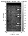
도 5b는 128개 지연들의 128개 세트에 대한 지연 인코딩된 합성 전송 개구를 나타내는 예시적인 이미지를 도시한다. 도 5b에 도시된 예시적인 지연 인코딩된 합성 전송 개구 이미지는 또한, Verasonics 초음파 촬영 시스템에 접속된 5 MHz에서 동작하는 Philips/ATL L7-5 선형 어레이를 이용하여 생성된, 예시적인 CIRS 모델 044 초음파 팬텀이다. 이미지는 54.0 dB의 동적 범위를 디스플레이한다. 이미지는 0 내지 30 파장에 걸친 128개 세트의 무작위 지연 인코딩 벡터들에 관한 코히어런트 합산의 결과이다. 도 5a와 비교할 때 상단 이미지의 상단 무반향 병변에서의 약간의 감소된 콘트라스트와 3개의 와이어 표적 각각의 위 및 아래의 아티팩트들이 있다. 주목할 점은, 예를 들어, 균등한 공간 샘플링으로 인해 이미지들 사이에는 약간의 유사성이 있다. 절대 이미지 밝기 레벨의 최상단 범위 187.0 dB는 144.8 dB에 비해 훨씬 크다. 또한, 지연 인코딩된 이미지에 대해 노이즈가 없는 침투 깊이가 훨씬 개선되어, 도 5a에 도시되지 않았지만, 80mm 깊이에서 무반향 표적(501로 라벨링된 박스로 도시됨)을 드러낸다.5B shows an example image showing a delay encoded composite transmission aperture for 128 sets of 128 delays. The example delay encoded composite transmission aperture image shown in FIG. 5B is also generated using an Philips/ATL L7-5 linear array operating at 5 MHz connected to a Verasonics ultrasound imaging system, an exemplary CIRS Model 044 ultrasound phantom. to be. The image displays a dynamic range of 54.0 dB. The image is the result of coherent summation for 128 sets of random delay encoding vectors spanning 0-30 wavelengths. There is a slight reduced contrast in the top anechoic lesion of the top image compared to FIG. 5A and artifacts above and below each of the three wire targets. Note that there is some similarity between the images due to, for example, uniform spatial sampling. The uppermost range of absolute image brightness level 187.0 dB is much larger than 144.8 dB. In addition, the noise-free penetration depth for the delay-encoded image is much improved, revealing an anechoic target (shown with a box labeled 501) at 80 mm depth, although not shown in FIG. 5A.
도 6a 및 도 6b는, 각각, 128개 지연들의 16개 세트에 대해 전체 합성 전송 개구 및 지연 인코딩된 합성 전송 개구를 통해 획득된 예시적인 이미지들을 도시한다. 도 6a는 다시, 도 6b와의 비교를 위해 55.2 dB의 동적 범위로 캡처된 전체 합성 전송 개구 이미지(즉, 도 1과 동일)를 도시한다. 도 6b는, Verasonics 초음파 촬영 시스템에 접속된 5 MHz에서 동작하는 Philips/ATL L7-5 선형 어레이를 이용하여 생성된 예시적인 CIRS 모델 044 초음파 팬텀의 지연 인코딩된 합성 전송 개구 이미지를 도시한다. 도 6b의 이미지에는, 52.0 dB의 동적 범위가 디스플레이되어 있다. 도 6b의 이미지는, (예를 들어, 도 5b의 128개 지연 세트에 비해) 0 내지 30 파장에 걸쳐 있는 16개 세트의 무작위 지연 인코딩 벡터들에 대한 코히어런트 합산의 결과이다. 예를 들어, 이미지에 도시된 바와 같이, 무작위 지연 패턴의 최적화는 없음에도 불구하고 공간 정보는 대체로 보존되지만, 중첩하는 에코들로 인해 모든 병변에서 콘트라스트가 감소한다. 예를 들어 도 6a에 비해, 지연 인코딩된 이미지에 대해 노이즈가 없는 침투 깊이가 훨씬 더 향상되어, 예를 들어, 8x 프레임 레이트 속도에도 불구하고, 80mm 깊이에서 무반향 표적(601로 라벨링된 박스로 도시됨)을 보여준다.6A and 6B show example images obtained through a full composite transmission aperture and a delay encoded composite transmission aperture for 16 sets of 128 delays, respectively. FIG. 6A again shows the overall composite transmission aperture image (ie, the same as FIG. 1) captured with a dynamic range of 55.2 dB for comparison with FIG. 6B. 6B shows a delay encoded composite transmission aperture image of an exemplary CIRS Model 044 ultrasound phantom generated using a Philips/ATL L7-5 linear array operating at 5 MHz connected to a Verasonics ultrasound imaging system. In the image of Fig. 6B, a dynamic range of 52.0 dB is displayed. The image of FIG. 6B is the result of coherent summation for 16 sets of random delay encoding vectors spanning 0-30 wavelengths (eg, compared to the 128 delay sets of FIG. 5B). For example, as shown in the image, although there is no optimization of the random delay pattern, spatial information is largely preserved, but the contrast is reduced in all lesions due to overlapping echoes. For example, compared to FIG. 6A, the noise-free penetration depth is much improved for delay-encoded images, for example, shown as an anechoic target (box labeled 601) at 80 mm depth despite the 8x frame rate. Will be displayed).
도 7a 및 7b는, 각각, 0 내지 1 파장에 걸친 128개 세트의 지연들에 대해 전체 합성 전송 개구 및 지연 인코딩된 합성 전송 개구를 통해 획득된 예시적인 이미지들을 도시한다. 도 7a는 비교를 위해 55.2 dB의 동적 범위로 캡처한 전체 합성 전송 개구 이미지(도 1과 동일)를 도시한다. 도 7b는, Verasonics 초음파 촬영 시스템에 접속된 5 MHz에서 동작하는 Philips/ATL L7-5 선형 어레이를 이용하여 생성된 예시적인 CIRS 모델 044 초음파 팬텀의 지연 인코딩된 합성 전송 개구 이미지를 도시한다. 도 7b의 이미지에는, 55.5 dB의 동적 범위가 디스플레이되어 있다. 도 7b의 이미지는 0 내지 1 파장에 걸친 128개 세트의 무작위 지연 인코딩 벡터들에 관한 코히어런트 합산의 결과이다. 이미지에 도시된 바와 같이, 예를 들어, 60mm 및 80mm 깊이의 무반향 병변에서의 콘트라스트는 도 5b에 이용된 30개 파장 인코딩된 지연에 비해 감소된다. 따라서, 도 5b에서의 80mm 깊이의 무반향 표적(501)은 도 7b에서 명백하지 않다.7A and 7B show example images obtained through a full composite transmission aperture and a delay encoded composite transmission aperture for 128 sets of delays spanning 0 to 1 wavelength, respectively. 7A shows the overall composite transmission aperture image (same as FIG. 1) captured with a dynamic range of 55.2 dB for comparison. 7B shows a delay encoded composite transmission aperture image of an exemplary CIRS model 044 ultrasound phantom generated using a Philips/ATL L7-5 linear array operating at 5 MHz connected to a Verasonics ultrasound imaging system. In the image of Fig. 7B, a dynamic range of 55.5 dB is displayed. The image in FIG. 7B is the result of coherent summation for 128 sets of random delay encoding vectors spanning 0 to 1 wavelength. As shown in the image, for example, contrast in anechoic lesions of 60 mm and 80 mm depth is reduced compared to the 30 wavelength encoded delay used in FIG. 5B. Thus, the 80 mm deep
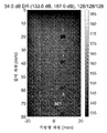
도 8a 및 도 8b는, 각각, 0 내지 1 파장에 걸친 16개 세트의 지연들에 대해 전체 합성 전송 개구 및 지연 인코딩된 합성 전송 개구를 통해 획득된 예시적인 이미지들을 도시한다. 도 8a는 비교를 위해 55.2 dB의 동적 범위로 캡처한 전체 합성 전송 개구 이미지(도 1과 동일)를 도시한다. 도 8b는, Verasonics 초음파 촬영 시스템에 접속된 5 MHz에서 동작하는 Philips/ATL L7-5 선형 어레이를 이용하여 생성된 예시적인 CIRS 모델 044 초음파 팬텀의 지연 인코딩된 합성 전송 개구 이미지를 도시한다. 도 8b의 이미지에는, 52.5 dB의 동적 범위가 디스플레이되어 있다. 도 8b의 이미지는 0 내지 1 파장에 걸친 16개 세트의 무작위 지연 인코딩 벡터들에 관한 코히어런트 합산의 결과이다. 예를 들어, 이미지에 도시된 바와 같이, 도 6b에서 이용된 30개의 파장 인코딩된 지연에 비해 와이어 주변에서 아티팩트들의 약간의 개선이 있지만, 60mm 및 80mm에서의 2개의 가장 깊은 병변의 콘트라스트는 감소한다. 깊이에 걸친 스트라이핑 아티팩트들은, 비최적의 지연 선택으로부터의 약간의 파괴적 간섭에 기인한 것이다. 또한, 8x의 프레임 레이트 속도를 갖더라도, 예를 들어, 도 8a에 비해, 지연 인코딩된 이미지에 대해 잡음이 없는 침투 깊이가 여전히 훨씬 개선된다.8A and 8B show example images obtained through a full composite transmission aperture and a delay encoded composite transmission aperture for 16 sets of delays spanning 0 to 1 wavelength, respectively. 8A shows the overall composite transmission aperture image (same as FIG. 1) captured with a dynamic range of 55.2 dB for comparison. 8B shows a delay encoded composite transmission aperture image of an exemplary CIRS model 044 ultrasound phantom generated using a Philips/ATL L7-5 linear array operating at 5 MHz connected to a Verasonics ultrasound imaging system. In the image of Fig. 8B, a dynamic range of 52.5 dB is displayed. The image in FIG. 8B is the result of coherent summation for 16 sets of random delay encoding vectors spanning 0 to 1 wavelength. For example, as shown in the image, there is a slight improvement in artifacts around the wire compared to the 30 wavelength encoded delay used in FIG. 6B, but the contrast of the two deepest lesions at 60mm and 80mm is reduced. . Striping artifacts across the depth are due to some destructive interference from non-optimal delay selection. Also, even with a frame rate of 8x, the noise-free penetration depth is still much improved for a delay encoded image, for example, compared to FIG. 8A.
개시된 방법들의 일부 실시예에서, 예를 들어 크로스토크가 결과적인 이미지에서 인지가능한 아티팩트들을 초래하지 않도록, 전송은 수신기로부터 전기적으로 음향적으로 격리된다. 전송 지연은 공간 및 시간 양쪽 모두에서 임의적일 수 있다. 예를 들어, 무작위로 지연된 전송들은 모든 요소들에 관해 독립적으로 무작위 펄스-반복 간격들로 진행할 수 있다. 게다가, 펄스 반복 간격은, 초음파 촬영에서 전형적으로 시행되는 바와 같이, 전송으로부터 수신까지의 왕복 시간과 같거나 이를 초과할 필요가 없다. 추가로, 전송은 공간 및 시간에 걸쳐 임의로 분산될 수 있기 때문에, 일부 실시예는 또한, 전송 멀티플렉서와 결합된 하나의 오직 한 세트의 전송기들만을 이용하여 전송 요소의 임의의 고속 선택을 허용하는 것을 포함한다. 전송기는 임의의 파형을 전송하도록 최적화될 수 있다. 일부 실시예에서, 수신기는, 프리 러닝(free running)될 수 있다, 예를 들어 빔형성기 하드웨어 내로 지속적으로 향하는 에코를 지속적으로 기록할 수 있다.In some embodiments of the disclosed methods, the transmission is electrically acoustically isolated from the receiver, for example, so that crosstalk does not result in recognizable artifacts in the resulting image. Transmission delay can be arbitrary in both space and time. For example, randomly delayed transmissions can proceed at random pulse-repeat intervals independently for all elements. Moreover, the pulse repetition interval need not be equal to or exceed the round-trip time from transmission to reception, as is typically done in ultrasound imaging. Additionally, because transmissions can be randomly distributed over space and time, some embodiments also allow for any high-speed selection of a transmission element using only one set of transmitters combined with a transmission multiplexer. Includes. The transmitter can be optimized to transmit arbitrary waveforms. In some embodiments, the receiver can be free running, for example continuously recording echoes that are continuously directed into the beamformer hardware.
개시된 방법들의 일부 실시예에서, 예를 들어, 전송 및 수신 양쪽 모두에 대해 동일한 어레이를 이용하여, 동시 동작을 위해 전송기 및 수신기를 전기적으로 분리하는 것이 가능하지 않을 수 있는 경우, 수신기들의 전부 또는 서브세트 상의 회로는 전송 크로스토크 신호를 말소하거나 임계값 아래로 감쇠시켜 이미지 아티팩트들을 인지 임계값 아래로 감소시킨다. 예를 들어, 전송과 동시에, 하나 이상의 수신기들은, 예를 들어 PIN 스위칭 다이오드 또는 유사한 고속, 고 대역폭 스위치를 이용하여 개별적으로 스위칭 오프되므로, 전송 신호가 수신기 전자회로를 포화시키는 것을 방지한다.In some embodiments of the disclosed methods, it may not be possible to electrically separate the transmitter and receiver for simultaneous operation, eg, using the same array for both transmission and reception, all or sub of the receivers Circuitry on the set either expunges the transmit crosstalk signal or attenuates below the threshold to reduce image artifacts below the perception threshold. For example, at the same time as the transmission, one or more receivers are individually switched off using, for example, a PIN switching diode or similar high-speed, high-bandwidth switch, thereby preventing the transmission signal from saturating the receiver electronics.
개시된 방법들의 일부 실시예에서, 수신기 채널들의 전부 또는 서브세트의 ADC 출력들은, 조정가능한 지연 및 지속 시간으로, 각각의 전송과 일치하여 나타나는 전송 크로스토크 신호를 말소하도록 디지털적으로 시그널링될 수 있다.In some embodiments of the disclosed methods, ADC outputs of all or a subset of the receiver channels can be digitally signaled to cancel the transmit crosstalk signal that appears in accordance with each transmission, with adjustable delay and duration.
개시된 방법들의 일부 실시예에서, 빔형성 전에, 전송 크로스토크 신호는 신호 처리를 이용하여 차단된다. 더욱이, 차단된 신호는, 신호 처리를 이용하여, 예를 들어, 보간법의 적용을 통해, 또는 하나 이상의 독립적인 전송 실현에 관한 하나 이상의 전송기 및/또는 수신기 조합에 걸쳐 공간적으로(예를 들어, 상호성) 및/또는 시간적으로 상관된 신호(예를 들어, 필터링)에 기초하여 누락된 샘플을 추정하는데 유용한 임의의 방법이나 알고리즘의 적용을 통해 복구될 수 있다.In some embodiments of the disclosed methods, prior to beamforming, the transmit crosstalk signal is blocked using signal processing. Moreover, the blocked signal may be spatially (eg, reciprocal), using signal processing, eg, through the application of interpolation, or across one or more transmitter and/or receiver combinations relating to one or more independent transmission realizations. ) And/or any method or algorithm useful for estimating missing samples based on temporally correlated signals (eg, filtering).
개시된 방법들의 일부 실시예에서, 지연-및-합산 빔형성기에서, 이미지 포인트까지의 중첩하는 도달 시간을 초래하는 특정한 전송기, 수신기 및/또는 지연 조합에 대응하는 에코 샘플은, 메모리에 저장되거나 빔형성기 내에서 계산된 미리결정된 패턴에 기초하여, 차단되거나, 생략되거나, 가중된다. 더욱이, 차단된 신호는, 신호 처리를 이용하여, 예를 들어, 보간법의 적용, 또는 하나 이상의 독립적인 전송 실현에 관한 하나 이상의 전송기 및/또는 수신기 조합에 걸쳐 공간적으로 및/또는 시간적으로 상관된 신호에 기초하여 누락된 샘플을 추정하는데 유용한 임의의 방법의 적용을 통해 복구될 수 있다.In some embodiments of the disclosed methods, in delay-and-sum beamformers, echo samples corresponding to specific transmitter, receiver and/or delay combinations resulting in overlapping arrival times to the image point are stored in memory or beamformer. Based on a predetermined pattern calculated within, it is blocked, omitted, or weighted. Moreover, the intercepted signal is spatially and/or temporally correlated across one or more transmitter and/or receiver combinations, e.g., with interpolation, or with one or more independent transmission realizations, using signal processing. Based on this, it can be recovered through the application of any method useful for estimating missing samples.
전송된 파형의 진폭 및/또는 위상 양쪽 모두의 고려를 통해 추가적인 공간 인코딩이 가능하게 된다. 진폭 인코딩은, 요소 인덱스 또는 공간 요소 위치에 대한 전송된 파형의 진폭을 변조함으로써 달성된다. 위상 인코딩은, 요소 인덱스 또는 공간 요소 위치에 대한 전송된 파형의 위상을 변조함으로써 달성된다. 일부 구현에서, 진폭 인코딩 및 위상 인코딩은, 음향 파형을 시간적으로 및 공간적으로 인코딩하기 위한 방법의 동일한 프로세스에서 달성될 수 있다. 예를 들어, 4-요소 2진 위상 인코딩 시퀀스 [1 -1 1 -1]와 결합된, 예컨대 [0.5 1.0 0.0 0.75]에 의해 주어진 4-요소 진폭 인코딩 시퀀스는, 4-요소 진폭 및 위상 인코딩된 시퀀스 [0.5 -1.0 0.0 -0.75]를 생성한다, 즉, 위상 시퀀스와의 진폭 시퀀스의 요소별 곱에 의해 생성된다.Additional spatial encoding is possible through consideration of both the amplitude and/or phase of the transmitted waveform. Amplitude encoding is achieved by modulating the amplitude of the transmitted waveform relative to the element index or spatial element position. Phase encoding is achieved by modulating the phase of the transmitted waveform relative to the element index or spatial element position. In some implementations, amplitude encoding and phase encoding can be achieved in the same process of the method for temporally and spatially encoding acoustic waveforms. For example, a 4-element amplitude encoding sequence combined with a 4-element binary phase encoding sequence [1 -1 1 -1], such as given by [0.5 1.0 0.0 0.75], is 4-element amplitude and phase encoded The sequence [0.5 -1.0 0.0 -0.75] is generated, that is, by the element-wise multiplication of the amplitude sequence with the phase sequence.
앞서 논의된 바와 같이, 움직임 효과를 완화하기 위해 모든 공간 주파수가 동시에 또는 거의 동시에 여기될 때 최상의 가능한 촬영 속도 및 해상도가 달성된다. 지연 인코딩은 준-동시 여기(nearly simultaneous excitation)로의 한 경로이지만, 더 많은 통계적으로 독립적인 지연된 에코 샘플들이 평균될 때 결국 평균으로 수렴되는 바람직하지 않은 중첩 에코들로부터 노이즈를 도입할 수 있다.As discussed above, the best possible shooting speed and resolution is achieved when all spatial frequencies are excited simultaneously or nearly simultaneously to mitigate the effects of motion. Delay encoding is one path to near-simultaneous simultaneous excitation, but may introduce noise from undesirable overlapping echoes that eventually converge to an average when more statistically independent delayed echo samples are averaged.
전송된 파형들의 진폭 및 위상은, 그들이 모든 공간 주파수를 동시에 인코딩하도록 및 그들이 상당한 SNR 이득으로 정확하게 또는 거의 정확한 방식으로 디코딩될 수 있도록 하는 고유한 방식으로 각각의 전송에 대해 변할 수 있다. 예를 들어, 4-요소 개구의 경우, 전송은, 정확히 진폭 4의 Kronecker 델타 함수인, 대응하는 원형 자기상관 [4 0 0 0]을 갖는, 2상 시퀀스 [1 -1 1 1]에 대응하는 공간 진폭 및 위상을 가질 수 있다. 마찬가지로, 8-요소 개구의 경우, 예를 들어 [1.00000 -0.91546 0.75184 0.99877 0.91478 0.23430 -0.50953 -0.31760]에 의해 주어지는 2상 진폭 변조된 시퀀스는, 예를 들어, 대략 진폭 4.6531의 Kronecker 델타 함수인, [4.6531 4.3314e-09 -9.2177e-10 6.1084e-09 1.6652e-08 6.1084e-09 -9.2177e-10 4.3314e-09]에 의해 주어지는 원형 자기상관을 갖는다.The amplitude and phase of the transmitted waveforms can be varied for each transmission in a unique way so that they encode all spatial frequencies simultaneously and that they can be decoded in a precise or nearly accurate manner with significant SNR gain. For example, in the case of a four-element aperture, the transmission corresponds to a two-phase sequence [1 -1 1 1], with a corresponding circular autocorrelation [4 0 0 0], which is exactly the Kronecker delta function of
일부 구현에서, 임의의 길이 시퀀스는, 래그-제로(lag-zero) 원형 자기상관을 최대화하고 다른 모든 래그를 최소화하도록 수치적으로 최적화될 수 있다. 16개의, 길이 16 무작위 진폭 및 위상 전송 공간 인코딩 벡터들의 수치적으로 최적화된 세트의 한 예가 도 9a에 도시되어 있고, 여기서, 전송 벡터들은 각각의 행에 있다. 이산 푸리에 변환의 대응하는 크기가 도 9b에 도시되어 있다. DC 값은 각각의 행에서 최좌측에 있다. 스펙트럼은 모든 인코딩 벡터들에 걸쳐 모든 공간 주파수들에 대해 ![]()
![]()
일부 구현에서, 임의의 길이 시퀀스는 또한, 예를 들어 2D 어레이에 관해 인코딩된 전송을 달성하기 위해 2차원 행렬에 대해 최적화될 수도 있다. 또한, 시퀀스는, 3차원 인코딩을 달성할 수 있는, 2개의 공간 차원 + 시간 차원에서의 인코딩된 전송을 달성하기 위해 3차원 행렬에 대해 최적화될 수 있다. 디코딩은 인코딩 벡터/행렬과의 직접 원형 정합된 필터 콘볼루션을 통해 적용될 수 있거나, 또는 이산 푸리에 변환, 또는 동등하게는, 계산적으로 바람직한 경우 고속 푸리에 변환의 이용을 통해, 주파수 영역에서 적용될 수 있다.In some implementations, any length sequence may also be optimized for a two-dimensional matrix, eg, to achieve encoded transmission for a 2D array. In addition, the sequence can be optimized for a three-dimensional matrix to achieve encoded transmission in two spatial dimensions + temporal dimension, which can achieve three-dimensional encoding. Decoding can be applied through direct circular matched filter convolution with an encoding vector/matrix, or, in the frequency domain, through the use of a discrete Fourier transform, or, equivalently, a fast Fourier transform if computationally desirable.
임의의 길이 시퀀스는 또한, 광학 촬영에 주로 적용되는 마스크 패턴인, 균일 중복 어레이(URA; uniformly redundant array)와 밀접한 관계가 있다. URA들은 2진이며, 이들은 그들의 정합되는 패턴과 상관될 때 유사한 Kronecker 델타 속성을 공유한다. URA들은 본질적으로, 훨씬 더 큰 개구를 이용하여 핀홀형 촬영 해상도를 가능케하여, 훨씬 더 많은 수신된 광과 더 높은 SNR을 제공한다. URA들은 주로 원격장 촬영(far field imaging)으로 제한된다; 그러나, 초음파 촬영은 개구의 근접장(near field)에서 발생하는 것으로 잘 알려져 있다.The arbitrary length sequence is also closely related to a uniformly redundant array (URA), a mask pattern mainly applied to optical imaging. URAs are binary, and they share similar Kronecker delta properties when correlated with their matching pattern. URAs essentially enable pinhole imaging resolution using a much larger aperture, providing much more received light and higher SNR. URAs are primarily limited to far field imaging; However, ultrasound imaging is well known to occur in the near field of the aperture.
개시된 기술은 초음파 촬영에서 이전에는 고려되지 않은 근접장 촬영 문제를 해결하기 위해 원격장 공간 인코딩 전략을 활용하는 고유한 속성을 갖는다. 지연-및-합산 빔형성기의 지연 컴포넌트가 근접장 에코를 원격장 균등물로 변환할 때, 공간 디코딩은 합산 전에 지연된 에코 샘플에 적용된다. 개시된 기술은 지연-및-합산 빔형성기의 샘플 지연 단계에서의 합산 전에 디코딩을 적용할 수 있다, 즉, 디코딩은 상이한 지연들을 갖는 에코 샘플들에 적용되며, 이것은, 디코딩이 동일한 지연으로 에코 샘플들에 적용되는 Hadamard 공간 인코딩에 관하여 전통적인 공간 인코딩/디코딩으로부터의 근본적인 이탈을 나타낸다.The disclosed technology has the unique property of utilizing a remote field spatial encoding strategy to solve the near field imaging problem not previously considered in ultrasound imaging. When the delay component of the delay-and-sum beamformer transforms the near-field echo to a remote field equivalent, spatial decoding is applied to the delayed echo sample before summation. The disclosed technique may apply decoding prior to summing in the sample delay stage of the delay-and-sum beamforming, i.e., decoding is applied to echo samples with different delays, which means that decoding is equal to the echo samples with the same delay. Represents a fundamental departure from traditional spatial encoding/decoding with respect to Hadamard spatial encoding applied to.
일부 실시예에서, 인코딩 벡터들은 상보적일 수 있다. 예를 들어, 인코딩 및 디코딩 벡터들은 동일하지 않을 수 있지만, 이들의 원형 상호상관이 Kronecker 델타 함수를 야기하는 반면, 그들의 개개의 원형 자기상관은 Kronecker 델타 함수가 아니다. 이것은 또한, 역공학(reverse engineering)으로부터의 관찰가능한 인코딩 벡터의 난독화(obfuscation)를 제공하여, 벡터 스크램블링, 다른 무작위 벡터와의 콘볼루션 등의 다른 난독화 기술에 대한 대안을 제공할 수 있다.In some embodiments, encoding vectors may be complementary. For example, encoding and decoding vectors may not be the same, but their circular cross-correlation results in the Kronecker delta function, while their individual circular autocorrelation is not the Kronecker delta function. It can also provide obfuscation of observable encoding vectors from reverse engineering, providing an alternative to other obfuscation techniques such as vector scrambling and convolution with other random vectors.
개시된 진폭 및 위상 및 지연 인코딩 전략의 예시적인 구현이, 0 내지 227.5 파장에 걸친 128개 세트의 무작위 지연 인코딩 벡터들과 결합된 128개 세트의 진폭 및 위상 인코딩 벡터들에 대해, 포인트 9 표적들에 대한 예시적인 시뮬레이션에서 테스트되었다. 시뮬레이션된 어레이는 5MHz에서 작동하는 Philips L7-4 선형 어레이를 이용했으며, 시뮬레이션은 Verasonics 촬영 시스템 소프트웨어 시뮬레이터를 이용하여 수행되었다.An exemplary implementation of the disclosed amplitude and phase and delay encoding strategy is to point 9 targets for 128 sets of amplitude and phase encoding vectors combined with 128 sets of random delay encoding vectors spanning 0 to 227.5 wavelengths. Was tested in an exemplary simulation. The simulated array used a Philips L7-4 linear array operating at 5 MHz, and the simulation was performed using a Verasonics imaging system software simulator.
도 10 및 도 11은, 지연 인코딩만으로 빔형성된(도 10), 및 진폭 및 위상 인코딩과 결합된 지연 인코딩으로 빔형성된(도 11) 9개의 포인트 표적들의 예시적인 이미지를 도시한다. 도 10은, 100 dB 동적 범위가 디스플레이된, 지연 인코딩만으로 빔형성된 9개의 포인트 표적들의 이미지를 도시한다. 측방향 차원(801로 라벨링됨)과 깊이 차원(803으로 라벨링됨)에서 에코 중첩으로 인한 아티팩트들(예를 들어, 산란 회색 픽셀들)에 유의한다. 도 11은, 100 dB 동적 범위가 디스플레이된, 진폭 및 위상 인코딩과 결합된 지연 인코딩으로 빔형성된 9개의 포인트 표적의 이미지를 도시한다. 예를 들어, 도 11에 도시된 바와 같이, 아티팩트들은 측방향 차원(805로 라벨링됨)에서 크게 감소되고, 예를 들어, 진폭 및 위상 공간 인코딩으로 인해 깊이 차원(807로 라벨링됨)에서 아티팩트 감소가 존재한다. 또한, 117.9 dB에 대한 123.2 dB의 더 큰 절대 이미지 크기가 있다는 점에 유의한다. 일부 실시예에서, 결합된 인코딩이 또한, 구현될 수 있다.10 and 11 show exemplary images of nine point targets beamformed with delay encoding alone (FIG. 10), and beamformed with delay encoding combined with amplitude and phase encoding (FIG. 11). 10 shows an image of nine point targets beamformed with only delay encoding, with a 100 dB dynamic range displayed. Note the artifacts due to echo overlap (eg scattered gray pixels) in the lateral dimension (labeled 801) and the depth dimension (labeled 803). 11 shows an image of 9 point targets beamformed with delay encoding combined with amplitude and phase encoding, with a 100 dB dynamic range displayed. For example, as shown in FIG. 11, artifacts are greatly reduced in the lateral dimension (labeled 805), and artifacts are reduced in the depth dimension (labeled 807) due to, for example, amplitude and phase space encoding. Exists. Also note that there is a larger absolute image size of 123.2 dB for 117.9 dB. In some embodiments, combined encoding can also be implemented.
진폭, 위상 및 지연 인코딩의 조합은, 공간 지연 인코딩의 앞서 언급된 모든 실시예에서 데이터 취득 속도를 개선하고 이미지 아티팩트들을 감소시키는데 이용될 수 있다. 예를 들어, 주어진 시야에 대해, 인코딩 지연은 전체 이미지에 걸쳐 중첩 에코의 평균 발생을 최소화하도록 최적화될 수 있다. 또한, 인터프레임 및 인트라프레임 이미지 후처리에서의 개선은, 개시된 실시예들에 대한 중대한 변경없이 이미지 품질을 개선하는데 큰 영향을 미칠 수 있다.The combination of amplitude, phase and delay encoding can be used to improve data acquisition speed and reduce image artifacts in all of the aforementioned embodiments of spatial delay encoding. For example, for a given field of view, the encoding delay can be optimized to minimize the average occurrence of overlapping echoes over the entire image. In addition, improvements in interframe and intraframe image post-processing can have a major impact on improving image quality without significant changes to the disclosed embodiments.
개시된 방법 및 시스템은 코딩된 파형과 완벽하게 호환되며, 코딩된 파형 전송들의 채널 분리 및 파형 다양성 양태로부터 혜택을 받을 것이다.The disclosed method and system is fully compatible with coded waveforms and will benefit from channel separation and waveform diversity aspects of coded waveform transmissions.
도 12는, 개시된 기술을 수용할 수 있는 하나의 예시적인 합성 전송 개구 음향 시스템의 블록도를 도시한다. 도 12에 도시된 바와 같이, 시스템은 음향 프로브 디바이스(920) 및 데이터 처리 유닛 또는 컴퓨터(930)와 전기적으로 통신하는 전송/수신 전자 모듈(910)을 포함한다. 전송/수신 전자 모듈(910)은, 개개의 생성된 코딩된 파형에 기초하여 하나 이상의 복합 파형(예를 들어, 코히어런트, 확산-스펙트럼, 순간-광대역, 코딩된 파형들)을 전송 및 수신하기 위한 프로브 디바이스(920)에 전달되는 복수의 채널 상에 개개의 코딩된 파형을 생성하도록 구성된다. 프로브 디바이스(920)는, 각각의 프로브 변환기 세그먼트와 통신하는 프로브 인터페이스 유닛과 통신하는 프로브 제어기 유닛을 포함한다. 전송의 경우, 프로브 제어기는, 전송/수신 전자 모듈(910)로부터, 프로브 변환기 세그먼트 상의 변환기 요소에 의해 변환된, 복수의 통신 채널을 통해 운반된 생성된 이산 파형들의 파형 정보를 수신하도록 동작할 수 있다. 프로브 인터페이스는, 파형 신호를 선택된 변환기 요소에 라우팅하는 회로를 포함한다. 프로브 디바이스(920)는, 신체 구조와 접촉하는 특정한 지오메트리를 갖는 하우징 몸체의 섹션 상에 배열된 하나의 변환기 세그먼트 또는 복수의 변환기 세그먼트의 어레이를 포함할 수 있다. 일부 실시예에서, 예를 들어, 섹션은, 납작한 형상을 포함할 수 있는 반면, 다른 실시예에서는 섹션은 만곡형 형상을 포함할 수 있다.12 shows a block diagram of one exemplary synthetic transmission aperture acoustic system that can accommodate the disclosed technology. As shown in FIG. 12, the system includes an
도 13는 프로브(920)의 180° 곡률을 따라 복수의 전송 위치로부터 합성 전송 개구 빔을 형성하는 복수의 변환기 세그먼트 상의 변환기 서브-어레이들에 의해 생성된 예시적인 복합 초음파 빔들의 도면을 도시한다. 도면에 도시된 바와 같이, 프로브(920)는 변환기 세그먼트들 중 하나 이상에 있는 하나 이상의 실제 개구 서브-어레이들 Sub1, Sub2, ... Sub N을 형성하는데 이용되는 복수의 변환기 세그먼트를 포함한다. 변환기 어레이를 형성하는 변환기 요소들의 일부 또는 전부는, 초음파 촬영을 위한 합성 전송 개구를 형성하는 복수의 서브-어레이 위상 중심 위치들로부터 표적에 전송되는, 개개의, 상호직교하는, 코딩된 음향 파형들의 하나 이상의 복합 음향 파형을 (예를 들어, 순차적으로, 동시에 또는 무작위로) 전송할 수 있다. 일부 구현에서, 변환기 세그먼트 상의 상이한 변환기 요소들은 (개개의, 상호직교하는, 코딩된 음향 파형에 기초하여 형성된) 전송된 음향 파형에 대응하는 귀환된 음향 파형들을 수신하는 수신 어레이를 형성하도록 선택될 수 있고, 여기서, 수신된 음향 파형은 표적의 적어도 일부로부터 산란되어 (예를 들어, 반사, 굴절, 회절, 지연 및/또는 감쇠되어) 귀환된다. 반면, 일부 구현 예에서, 전송 어레이를 형성하는 변환기 요소들의 일부 또는 전부는 또한, 전송된 음향 파형에 대응하는 귀환된 음향 파형들을 수신할 수 있다. 수신된 개개의 음향 파형들은 이로써 전송된 복합 음향 파형에 대응하는 하나 이상의 수신된 복합 파형을 형성한다.13 shows a diagram of exemplary complex ultrasound beams generated by transducer sub-arrays on a plurality of transducer segments forming a composite transmission aperture beam from a plurality of transmission locations along the 180° curvature of the
도 14는 임의의 세트의 어레이 요소들 상의 인코딩된 전송의 수학적 표현을 도시한다. 파형 ![]()
![]()
![]()
![]()
![]()
![]()
![]()
![]()
![]()
![]()
도 15는 16개의 어레이 요소로부터 전파 속도 c를 갖는 매체로의 코히어런트 전송의 예시적인 묘사를 도시한다. 도시된 파면(wavefront)들 각각은, 개구를 가로질러 일정한 지연을 수반한 단일 요소로부터 나온다. 각각의 파면은 고유 파형 인코딩 및/또는 진폭 및 위상 인코딩에 대응할 수 있다.15 shows an exemplary depiction of coherent transmission from 16 array elements to a medium with propagation rate c. Each of the wavefronts shown comes from a single element with a constant delay across the opening. Each wavefront can correspond to a unique waveform encoding and/or amplitude and phase encoding.
도 16는 16개의 어레이 요소로부터 전파 속도 c를 갖는 매체로의 코히어런트 전송의 예시적인 묘사를 도시한다. 도시된 파면(wavefront)들 각각은, 개구를 가로질러 무작위 지연 인코딩을 수반한 단일 요소로부터 나온다. 각각의 파면은 또한, 고유 파형 인코딩 및/또는 진폭 및 위상 인코딩에 대응할 수 있다.16 shows an exemplary depiction of coherent transmission from 16 array elements to a medium with propagation rate c. Each of the wavefronts shown comes from a single element with random delay encoding across the aperture. Each wavefront can also correspond to native waveform encoding and/or amplitude and phase encoding.
도 17은 임의의 세트의 어레이 요소들에 대한 빔형성 지오메트리를 도시한다. 벡터들 ![]()
![]()
빔형성기에서, 기하학적 포커싱 지연은, 다음과 같이, i번째 전송 요소로부터 이미지 포인트까지 및 다시 j번째 수신 요소로의 왕복 거리를 매체 속도 c로 나눈 값에 따라 계산된다 :In the beamformer, the geometric focusing delay is calculated according to the median speed c divided by the round trip distance from the i th transmission element to the image point and back to the j th reception element:
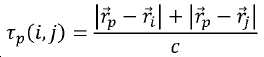
여기서, ![]()
![]()
![]()
![]()
도 18은, 각각이 중심 주파수 5MHz 및 -6 dB의 부분 대역폭 70%를 가지며 각각이 거의 이상적인 선형 자기상관 속성, 예를 들어 -60 dB 미만의 범위 로브를 갖는, 16개의 독립적인 인코딩 파형들의 예시적인 세트를 도시한다.FIG. 18 is an illustration of 16 independent encoding waveforms, each having a center frequency of 5 MHz and a partial bandwidth of 70% of -6 dB and each having nearly ideal linear autocorrelation properties, eg, a range lobe of less than -60 dB. Shows a set.
도 19는 0.196 마이크로초 내지 2.56 마이크로초 범위의 균일하고 무작위로 분포된 인코딩 지연들의 예시적인 시퀀스를 도시한다.19 shows an exemplary sequence of uniform and randomly distributed encoding delays ranging from 0.196 microseconds to 2.56 microseconds.
도 20은 도 19에 도시된 지연 인코딩을 갖는 도 18에 도시된 16개의 인코딩 파형들의 예시적인 세트를 도시한다.20 shows an exemplary set of 16 encoding waveforms shown in FIG. 18 with the delay encoding shown in FIG. 19.
도 21은 거의 이상적인 원형 자기상관 속성을 갖는 16개의 진폭 및 위상 인코딩 값들의 예시적인 시퀀스를 도시한다.21 shows an exemplary sequence of 16 amplitude and phase encoding values with near ideal circular autocorrelation properties.
도 22는 도 20에 도시된 시퀀스의 원형 자기상관을 도시하며, 2.09e-08 미만의 비제로 래그 값 및 래그 제로에서 선형 이득 8을 갖는 시퀀스의 거의 이상적인 Kronecker 델타 속성을 도시한다.FIG. 22 shows the circular autocorrelation of the sequence shown in FIG. 20 and shows the nearly ideal Kronecker delta property of a sequence with a non-zero lag value of less than 2.09e-08 and a linear gain of 8 at lag zero.
도 23은 도 21에 도시된 진폭 및 위상 인코딩을 갖는 도 20에 도시된 16개의 인코딩 파형들의 예시적인 세트를 도시한다.FIG. 23 shows an exemplary set of 16 encoding waveforms shown in FIG. 20 with the amplitude and phase encoding shown in FIG. 21.
도 24는 본 기술에 따른 디코딩 방법(2400)에 대한 예시적인 실시예의 도면을 도시한다. 일부 구현에서, 예를 들어, 방법(2400)은, 방법(200)의 프로세스 240에서 구현될 수 있다. 방법(2400)의 다양한 구현에서, 예를 들어, 어떤 인코딩 전략이 이용되는지에 따라, 예시적인 디코딩 방법(2400)은, (i) 코딩된 파형 디코딩(예를 들어, 범위 압축 및 직교성의 속성들을 동시에 충족시키는 임의의 파형, 및/또는 주파수 코딩된 및/또는 위상 코딩된 파형을 포함할 수 있는, 고유한 세트의 인코딩된 파형들의 디코딩), (ii) 전송 지연 패턴 디코딩, 및 (iii) 예를 들어, 방법(200)의 프로세스 210에서 상응하는 인코딩 기술들 중 어느 것이 이용되는지에 기초하여, 코딩된 파형 디코딩 스테이지, 전송 지연 패턴 디코딩 스테이지, 및/또는 전송 진폭 및 위상 패턴 디코딩 스테이지가 선택되는, 전송 진폭 및 위상 패턴 디코딩으로 구성된 최대 3개의 스테이지를 포함할 수 있다.24 shows a diagram of an exemplary embodiment of a
인코딩된 음향 신호를 수신한 후, 도 24의 도면의 2410에서, 디코딩 방법(2400)은, 이 예에서는 코딩된 파형들을 디코딩하는 프로세스(2420)를 구현하는 제1 디코딩 국면을 포함할 수 있다. 디코딩 방법(2400)은, 이 예에서는 전송 지연을 디코딩하는 프로세스(2430)를 구현하는 제2 디코딩 국면을 포함할 수 있다. 디코딩 방법(2400)은, 이 예에서는 진폭 및 위상을 디코딩하는 프로세스(2440)를 구현하는 제3 디코딩 국면을 포함할 수 있다. 디코딩 방법(2400)은 빔형성 프로세스(2450)를 포함할 수 있다. 예시적인 디코딩 방법의 프로세스들이 아래에서 설명된다.After receiving the encoded acoustic signal, at 2410 of the drawing of FIG. 24, the
도 24에 도시된 예시적인 절차는, 인코딩된 파형의 디코딩, 전송 지연의 디코딩, 및 진폭 및 위상의 디코딩을 포함한, 방법(2400)의 디코딩 스테이지들의 한 순서를 제시한다; 그러나, 절차는, 특정한 디코딩 순서, 또는 디코딩의 특정한 방법, 또는 특정한 디코딩 알고리즘으로 제한되지 않는다.The example procedure shown in FIG. 24 presents one sequence of decoding stages of
도 24에 도시된 예시적인 디코딩 방법(2400)에서, 제1 스테이지는, j번째 수신된 에코가 i번째 전송 파형의 시간 역전되고 및 켤레쌍 버전으로 필터링되어, 다음과 같은, 부분적으로 디코딩된 세트의 파형들을 생성하는 파형 디코딩을 포함한다 :In the
![]()
![]()
여기서, ![]()
![]()
![]()
![]()
![]()
![]()
![]()
![]()
디코딩 방법(2400)의 제2 스테이지는 지연 디코딩 프로세스를 포함할 수 있다. 파형 디코딩 스테이지의 출력은, 다음에 따라, 도 14에 도시된 인코딩 지연 ![]()
![]()
![]()
![]()
여기서, 윗첨자(d2)는 두번째 디코딩을 나타낸다. 여기서, ![]()
![]()
디코딩 방법(2400)의 제3 스테이지는 진폭 및 위상 디코딩을 포함할 수 있다. 지연 디코딩 스테이지의 출력은, 진폭 및 위상 인코딩 벡터 ![]()
![]()
![]()
![]()
![]()
![]()
여기서, 한 가능한 실시예에서, ![]()
![]()
![]()
![]()
![]()
![]()
![]()
![]()
![]()
![]()
예시적인 실시예에서, 포인트 p에 대한 빔형성된 샘플은 다음과 같이 모든 디코딩된 전송기 및 수신기 조합들에 대한 가중 합산에 의해 획득된다 :In the exemplary embodiment, the beamformed sample for point p is obtained by weighted summation for all decoded transmitter and receiver combinations as follows:
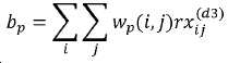
가중 또는 아포다이제이션(apodization) 함수 ![]()
![]()
![]()
![]()
예시적인 실시예에서, 빔형성된 샘플 ![]()
![]()
![]()
![]()

여기서 ![]()
![]()
![]()
![]()
마찬가지로, 빔형성된 샘플 시퀀스 ![]()
![]()
앞서 언급된 인코딩 및 디코딩 방식은 묵시적으로 1D 어레이에 대해 설명되었지만, 간단히, 적절한 어레이 요소 인덱싱 방식을 적용함으로써 임의의 지오메트리로 확장될 수 있다.The aforementioned encoding and decoding schemes have been implicitly described for 1D arrays, but can be simply extended to any geometry by applying an appropriate array element indexing scheme.
일부 예시적인 구현에서, 전체 인코딩 및 디코딩 프로세스를 미세 조정하기 위해 최적화가 수행될 수 있다. 예를 들어, 파형 인코딩, 진폭 인코딩, 및/또는 지연 인코딩은 오브젝트 함수(objection function)의 값을 최소화하기 위해 최적화기에 의해 수치적으로 변화될 수 있다. 오브젝션 함수는, 예를 들어, ![]()
![]()
![]()
![]()
여기서 합산은 모든 이미지 샘플들의 크기 제곱에 대해 취해진다. 비선형 최적화기는, 예를 들어, 전술된 디코딩 절차에 따라, 고정된 디코딩 절차가 주어지면 최상의 인코딩 파라미터들을 해결한다.Here the summation is taken for the squared size of all image samples. The nonlinear optimizer solves the best encoding parameters given a fixed decoding procedure, for example according to the decoding procedure described above.
예시적인 최적화는 또한, 고유한 세트들의 ![]()
![]()
![]()
![]()
![]()
![]()
예시적인 최적화는 비선형 머신 학습 알고리즘을 이용하여 달성될 수 있다. 예를 들어, 전체 합성 개구에 기초한 훈련 이미지 세트와 인코딩된 합성 개구 이미지 세트 사이의 에러가 최소화되도록 머신 러닝 알고리즘을 이용하여 한 세트의 인코딩 파라미터들이 학습된다.Exemplary optimization can be achieved using a nonlinear machine learning algorithm. For example, a set of encoding parameters are learned using a machine learning algorithm to minimize errors between a set of training images based on the entire composite aperture and a set of encoded composite aperture images.
예시적인 최적화는 훈련 이미지 세트 및 출력 이미지 세트 양쪽 모두를 생성하기 위해 최적화 또는 머신 학습 루프 내에서 촬영 시스템을 이용하여 온라인으로 달성될 수 있다.Exemplary optimization can be achieved online using an imaging system within an optimization or machine learning loop to generate both a training image set and an output image set.
예시적인 최적화는, 인위적으로 부과된 파형 인코딩, 진폭 및 위상 인코딩, 및 지연 인코딩과 함께 전체 합성 개구 데이터 세트를 이용하여 오프라인으로 달성될 수도 있다.Exemplary optimization may be achieved offline using the entire composite aperture data set with artificially imposed waveform encoding, amplitude and phase encoding, and delay encoding.
예들Examples
본 기술(예 A1)에 따른 일부 실시예에서, 생물학적 대상의 신체 구조와 인터페이싱하는 프로브 디바이스는, 변환기 요소들의 어레이를 포함하는 하나 이상의 변환기 세그먼트, 및 변환기 요소들의 어레이와 통신하여 파형들을 전송할 어레이의 변환기 요소들의 제1 서브세트를 선택하고, 귀환된 파형들을 수신할 어레이의 변환기 요소들의 제2 서브세트를 선택하는 프로브 제어기를 포함하고, 여기서, 변환기 요소들의 제1 서브세트는 생물학적 대상 내의 표적 체적을 향해 파형들을 전송하도록 배열되고, 변환기 요소들의 제2 서브세트는 표적 체적의 적어도 일부로부터 귀환하는 귀환된 파형들을 수신하도록 배열되며, 파형들은 미리결정된 전송 지연 패턴에 따라 전송된다. 프로브 디바이스는, 미리결정된 (i) 고유한 세트의 파형들, (ii) 전송 지연 패턴, 및/또는 (iii) 전송 진폭 및 위상 패턴을 포함하는 공간적으로 및 시간적으로 인코딩된 파형들을 표적 체적에 전송하도록 동작가능하고; 따라서, 표적으로부터 귀환된 음향 파형들을 수신한 후, 귀환된 파형들은, 각각의 전송 변환기 요소에 대응하는 파형 성분들을 각각의 수신 변환기 요소 상의 파형들로부터 분리되도록 처리함으로써 전체 합성 전송 개구 취득을 나타내는 한 세트의 파형들을 획득함으로써 디코딩된다.In some embodiments according to the present technology (Example A1), a probe device that interfaces with a biological subject's body structure includes one or more transducer segments comprising an array of transducer elements, and an array to transmit waveforms in communication with the array of transducer elements. And a probe controller that selects a first subset of transducer elements and selects a second subset of transducer elements of the array to receive the returned waveforms, wherein the first subset of transducer elements is a target volume within the biological object. Arranged to transmit the waveforms toward, a second subset of transducer elements are arranged to receive the returned waveforms from at least a portion of the target volume, and the waveforms are transmitted according to a predetermined transmission delay pattern. The probe device transmits spatially and temporally encoded waveforms to the target volume, including predetermined (i) unique sets of waveforms, (ii) transmission delay patterns, and/or (iii) transmission amplitude and phase patterns. Operable; Thus, after receiving the acoustic waveforms returned from the target, the returned waveforms represent the overall composite transmission aperture acquisition by processing the waveform components corresponding to each transmission transducer element to be separated from the waveforms on each reception transducer element. It is decoded by acquiring a set of waveforms.
예 A2는 예 A1의 프로브 디바이스를 포함하고, 미리결정된 전송 지연 패턴은 한 세트의 무작위 시간 지연들을 포함한다.Example A2 includes the probe device of Example A1, and the predetermined transmission delay pattern includes a set of random time delays.
예 A3은 예 A2의 프로브 디바이스를 포함하고, 상기 무작위 시간 지연들의 세트는 0 내지 상기 변환기 요소들의 어레이의 최대 용인 스탠드오프 거리까지에 걸친 범위 내에서 무작위 값들의 균일한 분포이다.Example A3 includes the probe device of Example A2, wherein the set of random time delays is a uniform distribution of random values within a range from 0 to the maximum acceptable standoff distance of the array of transducer elements.
예 A4는 예 A1의 프로브 디바이스를 포함하고, 상기 변환기 요소들의 제1 서브세트는 상기 변환기 요소들의 제2 서브세트와는 상이하다.Example A4 includes the probe device of Example A1, wherein the first subset of transducer elements is different from the second subset of transducer elements.
예 A5는 예 A1의 프로브 디바이스를 포함하고, 상기 변환기 요소들의 제1 서브세트는 상기 변환기 요소들의 제2 서브세트와 동일하다.Example A5 includes the probe device of Example A1, wherein the first subset of transducer elements is the same as the second subset of transducer elements.
예 A6은 예 A5의 프로브 디바이스를 포함하고, 상기 변환기 요소들의 제2 서브세트는 이미지 아티팩트들을 감소시키기 위해 전송 크로스토크 신호를 감쇠시킨다.Example A6 includes the probe device of Example A5, wherein the second subset of transducer elements attenuate the transmit crosstalk signal to reduce image artifacts.
예 A7은 예 A1의 프로브 디바이스를 포함하고, 상기 파형들은 각각의 전송에 대해 상이한 진폭들을 갖는다.Example A7 includes the probe device of Example A1, wherein the waveforms have different amplitudes for each transmission.
예 A8은 예 A1의 프로브 디바이스를 포함하고, 상기 파형들은 각각의 전송에 대해 상이한 위상들을 갖는다.Example A8 includes the probe device of Example A1, wherein the waveforms have different phases for each transmission.
예 A9는 예 A1의 프로브 디바이스를 포함하고, 각각의 전송에 대해 상이한 파형들이 이용된다.Example A9 includes the probe device of Example A1, and different waveforms are used for each transmission.
본 기술(실시예 A10)에 따른 일부 실시예에서, 신호 전송의 방법은, 제1 변환기 요소와 연관된 시간 지연 후에, 상기 제1 변환기 요소에 의해 생물학적 대상 내의 표적 체적을 향해 파형들을 전송하는 단계; 상기 제1 변환기 요소와 제2 변환기 요소 사이의 왕복 시간 후에, 상기 표적 체적의 적어도 일부로부터 귀환하는 귀환된 파형들을 상기 제2 변환기 요소에 의해 수신하는 단계; 상기 시간 지연 및 상기 왕복 시간에 기초하여 상기 귀환된 음향 파형들에 기여하는 상기 제1 변환기 요소를 식별하는 단계; 및 상기 생물학적 대상 내의 상기 표적 체적의 이미지를 생성하기 위해 상기 제1 변환기 요소의 식별에 기초하여 상기 귀환된 파형들을 처리하는 단계를 포함한다.In some embodiments according to the present technology (Embodiment A10), the method of signal transmission comprises: after a time delay associated with a first transducer element, transmitting waveforms by the first transducer element toward a target volume in a biological object; After the round-trip time between the first transducer element and the second transducer element, receiving, by the second transducer element, returned waveforms returning from at least a portion of the target volume; Identifying the first transducer element contributing to the returned acoustic waveforms based on the time delay and the round trip time; And processing the returned waveforms based on the identification of the first transducer element to create an image of the target volume in the biological object.
예 A11은 예 A10의 방법을 포함하고, 상기 시간 지연은 한 세트의 무작위 시간 지연들로부터 선택된다.Example A11 includes the method of Example A10, wherein the time delay is selected from a set of random time delays.
예 A12는 예 A11의 방법을 포함하고, 무작위 시간 지연들의 세트는, 0 내지, 상기 제1 및 제2 변환기 요소들의 최대 용인 스탠드오프 거리까지에 걸친 범위 내에서 무작위 값들의 균일한 분포이다.Example A12 includes the method of example A11, wherein the set of random time delays is a uniform distribution of random values within a range from 0 to the maximum tolerable standoff distance of the first and second transducer elements.
예 A13은 예 A10의 방법을 포함하고, 상기 제1 변환기 요소들은 상기 제2 변환기 요소들과는 상이하다.Example A13 includes the method of Example A10, wherein the first transducer elements are different from the second transducer elements.
예 A14는 예 A10의 방법을 포함하고, 상기 제1 변환기 요소들은 상기 제2 변환기 요소들과 동일하다.Example A14 includes the method of Example A10, wherein the first transducer elements are the same as the second transducer elements.
예 A15는 예 A14의 방법을 포함하고, 상기 제2 변환기 요소들은 이미지 아티팩트들을 감소시키기 위해 전송 크로스토크 신호를 감쇠시킨다.Example A15 includes the method of example A14, wherein the second transducer elements attenuate the transmit crosstalk signal to reduce image artifacts.
예 A16은 예 A10의 방법을 포함하고, 상기 파형들은 각각의 전송에 대해 상이한 진폭들을 갖는다.Example A16 includes the method of Example A10, wherein the waveforms have different amplitudes for each transmission.
예 A17은 예 A10의 방법을 포함하고, 상기 파형들은 각각의 전송에 대해 상이한 위상들을 갖는다.Example A17 includes the method of Example A10, wherein the waveforms have different phases for each transmission.
예 A18은 예 A10의 방법을 포함하고, 각각의 전송에 대해 상이한 파형들이 이용된다.Example A18 includes the method of Example A10, and different waveforms are used for each transmission.
본 기술(실시예 B1)에 따른 일부 실시예에서, 합성 개구 음향 촬영에서 음향 파형들의 공간 및 시간 인코딩을 위한 방법은, (i) 고유한 세트의 코딩된 파형들, (ii) 표적 체적에 전송될 음향 파형들에 대한 시간 지연들의 전송 지연 패턴, 또는 (iii) 표적 체적에 전송될 음향 파형들의 전송 진폭 및 위상 패턴 중 하나 이상을 생성하는 단계를 포함하는, 표적 체적을 향한 전송을 위해 한 세트의 공간 및 시간 인코딩된 음향 파형들을 생성하는 단계; 음향 프로브 디바이스의 하나 이상의 변환기 세그먼트에 대한 변환기 요소들의 어레이 상에 형성된 공간적으로 샘플링된 개구를 이용하여, 공간 및 시간 인코딩된 음향 파형들을 상기 표적 체적을 향해 코히어런트 전송하는 단계, ―전송에 이용되는 각각의 변환기 요소에는 제1 인덱스 번호 1 내지 i가 할당되고, i는 변환기 요소들의 총수 이하의 수임 ―; 공간적으로 샘플링된 개구 상에서 귀환된 인코딩된 음향 파형들을 수신하는 단계, ―여기서, 변환기 요소들에는 제2 인덱스 번호 1 내지 j가 할당되고, j는 변환기 요소들의 총수 이하인 수임―; 상기 표적 체적의 한 세트의 이미지 포인트들에 대응하는 상기 j번째 수신에서 상기 i번째 전송을 분리하기 위해 상기 귀환된 인코딩된 음향 파형들을 디코딩하는 단계; 및 상기 표적 체적의 이미지 포인트들의 세트 중의 각각의 이미지 포인트에 대해 분리된 에코 샘플들을 빔형성하기 위해 상기 디코딩된 귀환된 인코딩된 음향 파형들을 처리하는 단계를 포함한다.In some embodiments according to the present technology (Example B1), the method for spatial and temporal encoding of acoustic waveforms in composite aperture acoustic imaging comprises: (i) a unique set of coded waveforms, (ii) transmission to a target volume One set for transmission towards the target volume, comprising generating one or more of a transmission delay pattern of time delays for the acoustic waveforms to be, or (iii) a transmission amplitude and phase pattern of acoustic waveforms to be transmitted to the target volume. Generating spatial and time-encoded acoustic waveforms; Coherently transmitting spatially and temporally encoded acoustical waveforms towards the target volume using spatially sampled apertures formed on an array of transducer elements for one or more transducer segments of an acoustic probe device, for use in transmission The
예 B2는 예 B1의 방법을 포함하고, 상기 빔형성된 분리된 에코 샘플들과 연관된 데이터를 처리함으로써 상기 표적 체적의 이미지를 형성하는 단계를 더 포함한다.Example B2 includes the method of Example B1, further comprising forming an image of the target volume by processing data associated with the beamformed separated echo samples.
예 B3은 예 B1의 방법을 포함하고, 상기 전송될 음향 파형들에 대한 전송 지연 패턴에서의 각각의 시간 지연은 한 세트의 무작위 시간 지연들로부터 선택된다.Example B3 includes the method of example B1, wherein each time delay in the transmission delay pattern for the acoustic waveforms to be transmitted is selected from a set of random time delays.
예 B4는 예 B3의 방법을 포함하고, 무작위 시간 지연들의 세트는, 0 내지 2개 이상의 변환기 요소들 사이의 최대 용인 스탠드오프 거리까지에 걸친 범위 내에서 무작위 값들의 균일한 분포를 포함한다.Example B4 includes the method of example B3, and the set of random time delays includes a uniform distribution of random values within a range ranging from 0 to 2, the maximum tolerable standoff distance between two or more transducer elements.
예 B5는 예 B1의 방법을 포함하고, 음향 파형들에 대한 시간 지연들의 전송 지연 패턴을 생성하는 단계는, 하나 이상의 변환기 세그먼트에 대한 상기 어레이의 모든 변환기 요소들에 대해 독립적으로 무작위 펄스 반복 간격들에서의 음향 파형들의 전송을 허용하기 위해 무작위로 지연된 전송 시간들을 생성하는 단계를 포함한다.Example B5 includes the method of example B1, and generating a transmission delay pattern of time delays for acoustic waveforms comprises: random pulse repetition intervals independently for all transducer elements of the array for one or more transducer segments. And generating randomly delayed transmission times to allow transmission of acoustic waveforms at.
예 B6은 예 B1의 방법을 포함하고, 음향 파형들의 전송 진폭 및 위상 패턴을 생성하는 단계는, 변환기 요소 인덱스 또는 상기 변환기 요소의 공간 위치에 관하여 전송될 각각의 음향 파형에 대한 진폭을 변조하고 위상을 변조하는 단계를 포함한다.Example B6 includes the method of Example B1, wherein generating the transmission amplitude and phase pattern of the acoustic waveforms modulates and phases the amplitude for each acoustic waveform to be transmitted relative to the transducer element index or spatial location of the transducer element. It includes the step of modulating.
예 B7은 예 B1의 방법을 포함하고, 인코딩된 음향 파형들은 각각의 전송에 대해 상이한 진폭들을 갖는다.Example B7 includes the method of example B1, and the encoded acoustic waveforms have different amplitudes for each transmission.
예 B8은 예 B1의 방법을 포함하고, 인코딩된 음향 파형들은 각각의 전송에 대해 상이한 위상들을 갖는다.Example B8 includes the method of Example B1, and the encoded acoustic waveforms have different phases for each transmission.
예 B9는 예 B1의 방법을 포함하고, 고유한 세트의 코딩된 파형들은 범위 압축 및 직교성의 속성들을 동시에 충족시키는 임의의 파형들을 포함한다.Example B9 includes the method of example B1, and the unique set of coded waveforms includes arbitrary waveforms that simultaneously meet the properties of range compression and orthogonality.
본 기술(예 B10)에 따른 일부 실시예에서, 생물학적 대상의 신체 구조와 인터페이싱하는 음향 프로브 디바이스는, 변환기 요소들의 어레이를 포함하는 하나 이상의 변환기 세그먼트, 및 변환기 요소들의 어레이와 통신하여 음향 파형들을 전송할 어레이의 변환기 요소들의 제1 서브세트를 선택하고, 귀환된 음향 파형들을 수신할 어레이의 변환기 요소들의 제2 서브세트를 선택하는 프로브 제어기를 포함하고, 여기서, 변환기 요소들의 제1 서브세트는 생물학적 대상 내의 표적 체적을 향해 음향 파형들을 전송하도록 배열되고, 변환기 요소들의 제2 서브세트는 표적 체적의 적어도 일부로부터 귀환하는 귀환된 음향 파형들을 수신하도록 배열되며, 상기 프로브 디바이스는, 상기 귀환된 음향 파형들 각각이 서로 구별가능하도록 전송 파형들을 공간 및 시간 인코딩하는 미리결정된 전송 지연 패턴에 따라 상기 음향 파형들을 전송하도록 동작가능하다.In some embodiments according to the present technology (Example B10), an acoustic probe device that interfaces with a biological subject's body structure communicates with one or more transducer segments comprising an array of transducer elements, and an array of transducer elements to transmit acoustic waveforms. And a probe controller that selects a first subset of transducer elements of the array and selects a second subset of transducer elements of the array to receive the returned acoustic waveforms, wherein the first subset of transducer elements is a biological object. Arranged to transmit acoustic waveforms towards a target volume within, a second subset of transducer elements is arranged to receive returned acoustic waveforms from at least a portion of the target volume, and the probe device is configured to: It is operable to transmit the acoustic waveforms according to a predetermined transmission delay pattern that spatially and temporally encodes the transmission waveforms so that each is distinguishable from each other.
예 B11은 예 B10의 디바이스를 포함하고, 상기 미리결정된 전송 지연 패턴은 한 세트의 무작위 시간 지연들을 포함한다.Example B11 includes the device of Example B10, and the predetermined transmission delay pattern includes a set of random time delays.
예 B12는 예 B11의 디바이스를 포함하고, 상기 무작위 시간 지연들의 세트는 0 내지 상기 변환기 요소들의 어레이의 최대 용인 스탠드오프 거리까지에 걸친 범위 내에서 무작위 값들의 균일한 분포를 포함한다.Example B12 includes the device of Example B11, wherein the set of random time delays comprises a uniform distribution of random values within a range from 0 to the maximum acceptable standoff distance of the array of transducer elements.
예 B13은 예 B10의 디바이스를 포함하고, 상기 변환기 요소들의 제1 서브세트는 상기 변환기 요소들의 제2 서브세트와는 상이하다.Example B13 includes the device of Example B10, wherein the first subset of transducer elements is different from the second subset of transducer elements.
예 B14는 예 B10의 디바이스를 포함하고, 상기 변환기 요소들의 제1 서브세트는 상기 변환기 요소들의 제2 서브세트와 동일하다.Example B14 includes the device of Example B10, wherein the first subset of transducer elements is the same as the second subset of transducer elements.
예 B15는 예 B14의 디바이스를 포함하고, 상기 변환기 요소들의 제2 서브세트는 이미지 아티팩트들을 감소시키기 위해 전송 크로스토크 신호를 감쇠시킨다.Example B15 includes the device of example B14, wherein the second subset of transducer elements attenuate the transmit crosstalk signal to reduce image artifacts.
예 B16은 예 B10의 디바이스를 포함하고, 상기 음향 파형들은 각각의 전송에 대해 상이한 진폭들을 갖는다.Example B16 includes the device of Example B10, wherein the acoustic waveforms have different amplitudes for each transmission.
예 B17은 예 B10의 디바이스를 포함하고, 상기 음향 파형들은 각각의 전송에 대해 상이한 위상들을 갖는다.Example B17 includes the device of Example B10, wherein the acoustic waveforms have different phases for each transmission.
예 B18은 예 B10의 디바이스를 포함하고, 각각의 전송에 대해 상이한 주파수-코딩된 또는 위상-코딩된 파형들이 이용된다.Example B18 includes the device of Example B10, and different frequency-coded or phase-coded waveforms are used for each transmission.
본 기술(실시예 B19)에 따른 일부 실시예에서, 신호 전송의 방법은, 제1 변환기 요소와 연관된 시간 지연 후에, 상기 제1 변환기 요소에 의해 생물학적 대상 내의 표적 체적을 향해 음향 파형들을 전송하는 단계; 상기 제1 변환기 요소와 제2 변환기 요소 사이의 왕복 시간 후에, 상기 표적 체적의 적어도 일부로부터 귀환하는 귀환된 음향 파형들을 상기 제2 변환기 요소에 의해 수신하는 단계; 상기 시간 지연 및 상기 왕복 시간에 기초하여 상기 귀환된 음향 파형들에 기여하는 상기 제1 변환기 요소를 식별하는 단계; 및 상기 생물학적 대상 내의 상기 표적 체적의 이미지를 생성하기 위해 상기 제1 변환기 요소의 식별에 기초하여 상기 귀환된 음향 파형들을 처리하는 단계를 포함한다.In some embodiments according to the present technology (Embodiment B19), the method of signal transmission comprises, after a time delay associated with a first transducer element, transmitting acoustic waveforms by the first transducer element toward a target volume in a biological object. ; Receiving, after the round-trip time between the first transducer element and the second transducer element, the returned acoustic waveforms from at least a portion of the target volume by the second transducer element; Identifying the first transducer element contributing to the returned acoustic waveforms based on the time delay and the round trip time; And processing the returned acoustic waveforms based on the identification of the first transducer element to create an image of the target volume in the biological object.
예 B20은 예 B19의 방법을 포함하고, 상기 시간 지연은 무작위 시간 지연들의 세트로부터 선택된다.Example B20 includes the method of Example B19, wherein the time delay is selected from a set of random time delays.
예 B21은 예 B20의 방법을 포함하고, 무작위 시간 지연들의 세트는, 0 내지, 상기 제1 및 제2 변환기 요소들의 최대 용인 스탠드오프 거리까지에 걸친 범위 내에서 무작위 값들의 균일한 분포를 포함한다.Example B21 includes the method of example B20, and the set of random time delays includes a uniform distribution of random values within a range from 0 to the maximum tolerable standoff distance of the first and second transducer elements. .
예 B22는 예 B19의 방법을 포함하고, 상기 제1 변환기 요소는 상기 제2 변환기 요소와는 상이하다.Example B22 includes the method of Example B19, wherein the first transducer element is different from the second transducer element.
예 B23은 예 B19의 방법을 포함하고, 상기 제1 변환기 요소는 상기 제2 변환기 요소와 동일하다.Example B23 includes the method of Example B19, wherein the first transducer element is the same as the second transducer element.
예 B24는 예 B23의 방법을 포함하고, 상기 제2 변환기 요소는 이미지 아티팩트들을 감소시키기 위해 전송 크로스토크 신호를 감쇠시킨다.Example B24 includes the method of example B23, wherein the second transducer element attenuates the transmit crosstalk signal to reduce image artifacts.
예 B25는 예 B19의 방법을 포함하고, 상기 음향 파형들은 각각의 전송에 대해 상이한 진폭들을 갖는다.Example B25 includes the method of Example B19, wherein the acoustic waveforms have different amplitudes for each transmission.
예 B26은 예 B19의 방법을 포함하고, 상기 음향 파형들은 각각의 전송에 대해 상이한 위상들을 갖는다.Example B26 includes the method of Example B19, wherein the acoustic waveforms have different phases for each transmission.
예 B27은 예 B19의 방법을 포함하고, 각각의 전송에 대해 상이한 주파수-코딩된 또는 위상-코딩된 파형들이 이용된다.Example B27 includes the method of Example B19, and different frequency-coded or phase-coded waveforms are used for each transmission.
본 설명에서, "예시적인"이라는 용어는, 예, 사례, 또는 예시로서 역할한다는 것을 의미하기 위해 사용된다. 여기서 "예시적인"이라고 설명된 임의의 실시예 또는 설계는 다른 실시예 또는 설계에 비해 반드시 바람직하거나 유익한 것으로 해석되는 것은 아니다. 오히려, 예시적인이라는 용어의 사용은 개념을 구체적인 방식으로 제시하기 위한 것이다.In this description, the term "exemplary" is used to mean serving as an example, instance, or example. Any embodiment or design described herein as “exemplary” is not necessarily interpreted as being advantageous or advantageous over other embodiments or designs. Rather, the use of the term exemplary is intended to present concepts in a concrete manner.
본 명세서는 도면과 함께 단지 예시적인 것으로 간주되며, 예시라는 말은 한 예를 의미하는 것으로 의도된다. 본 명세서에서 사용될 때, 단수 형태, "a", "an", "the"는, 문맥상 명확하게 달리 표시하지 않는 한, 복수 형태도 역시 포함하는 것을 의도한다. 추가적으로, "또는"의 사용은, 문맥상 명백하게 달리 나타내지 않는 한, "및/또는"을 포함하는 것으로 의도된다.This specification is considered to be illustrative only with the drawings, and the word illustration is intended to mean one example. As used herein, singular forms, "a", "an", and "the" are intended to include plural forms also, unless the context clearly indicates otherwise. Additionally, the use of “or” is intended to include “and/or” unless the context clearly dictates otherwise.
본 특허 문서가 많은 특정한 사항들을 포함하지만, 이들은 본 발명의 범위의 또는 청구 범위에 관한 제한으로서 해석되어서는 안 되고, 특정한 발명의 특정한 실시예들 고유의 피쳐들의 설명으로서 해석되어야 한다. 별개의 실시예들의 정황에서 본 특허 문서에서 설명된 소정 피쳐들은 또한, 단일의 실시예에서 조합하여 구현될 수 있다. 역으로, 단일 실시예의 정황에서 설명된 다양한 피쳐들은 또한, 복수의 실시예에서 별개로 구현되거나 임의의 적절한 하위조합(subcombination)으로 구현될 수 있다. 게다가, 피쳐들이 상기에서 소정 조합으로 작용하는 것으로 설명되거나 심지어 그와 같이 처음 청구되더라도, 청구된 조합으로부터의 하나 이상의 피쳐들은 일부 경우에는 그 조합으로부터 삭제될 수도 있고, 청구된 조합은 하위조합이나 하위조합의 변형에 관한 것일 수도 있다.Although this patent document includes many specific matters, they should not be construed as limitations of the scope of the invention or as claims, but as a description of features unique to specific embodiments of the particular invention. Certain features that are described in this patent document in the context of separate embodiments may also be implemented in combination in a single embodiment. Conversely, various features described in the context of a single embodiment may also be implemented separately in multiple embodiments or in any suitable subcombination. Moreover, even if features are described above acting in a given combination, or even first billed as such, one or more features from the claimed combination may in some cases be deleted from the combination, and the claimed combination may be a subcombination or sub It may also be about a variation of the combination.
유사하게, 동작들이 도면에서 특정 순서로 도시되더라도, 이것은, 바람직한 결과를 달성하기 위해 이러한 동작들이 도시된 특정 순서로 또는 순차적 순서로 수행될 것을 요구하거나, 도시된 모든 동작들이 수행될 것을 요구하는 것으로 이해되어서는 안 된다. 또한, 본 특허 문서에서 설명된 실시예들에서의 다양한 시스템 컴포넌트들의 분리는 모든 실시예에서 이러한 분리를 요구하는 것으로 이해되어서는 안 된다.Similarly, although the operations are shown in a specific order in the drawings, this requires that these actions be performed in a specific order or in a sequential order shown, or that all actions shown are performed to achieve the desired result. It should not be understood. Also, the separation of various system components in the embodiments described in this patent document should not be understood as requiring such separation in all embodiments.
단지 몇 개의 구현 및 예들만이 설명되었지만, 본 특허 문서에서 설명되고 예시된 내용에 기초하여 다른 구현, 개선 및 변형이 이루어질 수 있다.Although only a few implementations and examples have been described, other implementations, improvements and variations can be made based on the content described and illustrated in this patent document.
Claims (27)
(i) 고유한 세트의 코딩된 파형들, (ii) 표적 체적에 전송될 음향 파형들에 대한 시간 지연들의 전송 지연 패턴, 또는 (iii) 상기 표적 체적에 전송될 음향 파형들의 전송 진폭 및 위상 패턴 중에서, 하나 이상을 생성하는 단계를 포함하는, 상기 표적 체적을 향한 전송을 위한 한 세트의 공간 및 시간 인코딩된 음향 파형들을 생성하는 단계;
음향 프로브 디바이스의 하나 이상의 변환기 세그먼트에 대한 변환기 요소들의 어레이 상에 형성된 공간적으로 샘플링된 개구를 이용하여, 공간 및 시간 인코딩된 음향 파형들을 상기 표적 체적을 향해 코히어런트 전송(coherently transmit)하는 단계, ―상기 전송에 이용되는 각각의 변환기 요소에는 제1 인덱스 번호 1 내지 i가 할당되고, i는 변환기 요소들의 총수 이하의 수임 ―;
상기 공간적으로 샘플링된 개구 상에서 귀환된 인코딩된 음향 파형들을 수신하는 단계, ―상기 변환기 요소들에는 제2 인덱스 번호 1 내지 j가 할당되고, j는 변환기 요소들의 총수 이하인 수임―;
상기 표적 체적의 한 세트의 이미지 포인트들에 대응하는 상기 j번째 수신에서 상기 i번째 전송을 분리하기 위해 상기 귀환된 인코딩된 음향 파형들을 디코딩하는 단계; 및
상기 표적 체적의 상기 이미지 포인트들의 세트 중의 각각의 이미지 포인트에 대해 분리된 에코 샘플들을 빔형성하기 위해 상기 디코딩된 귀환된 인코딩된 음향 파형들을 처리하는 단계
를 포함하는 방법.A method for spatial and temporal encoding of acoustic waveforms in composite aperture acoustic imaging,
(i) a unique set of coded waveforms, (ii) a transmission delay pattern of time delays for acoustic waveforms to be transmitted to a target volume, or (iii) a transmission amplitude and phase pattern of acoustic waveforms to be transmitted to the target volume. Among them, generating one or more sets of spatial and time encoded acoustic waveforms for transmission towards the target volume, comprising generating one or more;
Coherently transmitting spatially and temporally encoded acoustical waveforms towards the target volume, using spatially sampled apertures formed on an array of transducer elements for one or more transducer segments of an acoustic probe device, -Each converter element used for the transmission is assigned a first index number 1 to i, and i is a number equal to or less than the total number of converter elements;
Receiving encoded acoustic waveforms returned on the spatially sampled aperture, wherein the converter elements are assigned second index numbers 1 to j, and j is a number equal to or less than the total number of converter elements;
Decoding the returned encoded acoustic waveforms to separate the i-th transmission from the j-th reception corresponding to the set of image points of the target volume; And
Processing the decoded returned encoded acoustic waveforms to beamform separate echo samples for each image point in the set of image points of the target volume.
How to include.
변환기 요소들의 어레이를 포함하는 하나 이상의 변환기 세그먼트; 및
상기 변환기 요소들의 어레이와 통신하여 음향 파형들을 전송할 상기 어레이의 변환기 요소들의 제1 서브세트의 선택, 및 귀환된 음향 파형들을 수신할 상기 어레이의 변환기 요소들의 제2 서브세트의 선택을 인에이블하는 프로브 제어기를 포함하고,
상기 변환기 요소들의 제1 서브세트는 상기 생물학적 대상 내의 표적 체적을 향해 상기 음향 파형들을 전송하도록 배열되고, 상기 변환기 요소들의 제2 서브세트는 상기 표적 체적의 적어도 일부로부터 귀환하는 귀환된 음향 파형들을 수신하도록 배열되며,
상기 음향 프로브는, 상기 귀환된 음향 파형들 각각이 서로 구별가능하도록 전송 파형들을 공간 및 시간 인코딩하는 미리결정된 전송 지연 패턴에 따라 상기 음향 파형들을 전송하도록 동작가능한, 음향 프로브.Acoustic probe that interfaces with the body structure of a biological object,
One or more transducer segments comprising an array of transducer elements; And
A probe in communication with the array of transducer elements to enable selection of a first subset of transducer elements of the array to transmit acoustic waveforms, and selection of a second subset of transducer elements of the array to receive returned acoustic waveforms Including a controller,
The first subset of transducer elements are arranged to transmit the acoustic waveforms towards a target volume in the biological object, and the second subset of transducer elements receive returned acoustic waveforms from at least a portion of the target volume Is arranged,
And the acoustic probe is operable to transmit the acoustic waveforms according to a predetermined transmission delay pattern that spatially and temporally encodes the transmitted waveforms so that each of the returned acoustic waveforms is distinguishable from each other.
제1 변환기 요소와 연관된 시간 지연 후, 생물학적 대상 내의 표적 체적을 향해 음향 파형들을 제1 변환기 요소에 의해 전송하는 단계;
상기 제1 변환기 요소와 제2 변환기 요소 사이의 왕복 시간 후에, 상기 표적 체적의 적어도 일부로부터 귀환하는 귀환된 음향 파형들을 상기 제2 변환기 요소에 의해 수신하는 단계;
상기 시간 지연 및 상기 왕복 시간에 기초하여 상기 귀환된 음향 파형들에 기여하는 상기 제1 변환기 요소를 식별하는 단계; 및
생물학적 대상 내의 상기 표적 체적의 이미지를 생성하기 위해 상기 제1 변환기 요소의 식별에 기초하여 상기 귀환된 음향 파형들을 처리하는 단계
를 포함하는 방법.As a signal transmission method,
After a time delay associated with the first transducer element, transmitting acoustic waveforms by the first transducer element towards a target volume in the biological object;
Receiving, after the round-trip time between the first transducer element and the second transducer element, the returned acoustic waveforms from at least a portion of the target volume by the second transducer element;
Identifying the first transducer element contributing to the returned acoustic waveforms based on the time delay and the round trip time; And
Processing the returned acoustic waveforms based on the identification of the first transducer element to create an image of the target volume in a biological object.
How to include.
Applications Claiming Priority (3)
| Application Number | Priority Date | Filing Date | Title |
|---|---|---|---|
| US201762578351P | 2017-10-27 | 2017-10-27 | |
| US62/578,351 | 2017-10-27 | ||
| PCT/US2018/057891 WO2019084526A1 (en) | 2017-10-27 | 2018-10-27 | Spatial and temporal encoding of acoustic waveforms for full synthetic transmit aperture imaging |
Publications (1)
| Publication Number | Publication Date |
|---|---|
| KR20200080276A true KR20200080276A (en) | 2020-07-06 |
Family
ID=66247046
Family Applications (1)
| Application Number | Title | Priority Date | Filing Date |
|---|---|---|---|
| KR1020207015032A KR20200080276A (en) | 2017-10-27 | 2018-10-27 | Spatial and temporal encoding of acoustic waveforms for whole composite transmission aperture imaging |
Country Status (6)
| Country | Link |
|---|---|
| US (1) | US11860273B2 (en) |
| EP (1) | EP3701279A4 (en) |
| JP (1) | JP2021500966A (en) |
| KR (1) | KR20200080276A (en) |
| CA (1) | CA3080561A1 (en) |
| WO (1) | WO2019084526A1 (en) |
Cited By (1)
| Publication number | Priority date | Publication date | Assignee | Title |
|---|---|---|---|---|
| KR20220168728A (en) * | 2021-06-17 | 2022-12-26 | 국방과학연구소 | Apparatus and method for generating a range-doppler map using data correlation in a rader system |
Families Citing this family (6)
| Publication number | Priority date | Publication date | Assignee | Title |
|---|---|---|---|---|
| EP2771712B1 (en) | 2011-10-28 | 2023-03-22 | Decision Sciences International Corporation | Spread spectrum coded waveforms in ultrasound imaging |
| US9844359B2 (en) | 2013-09-13 | 2017-12-19 | Decision Sciences Medical Company, LLC | Coherent spread-spectrum coded waveforms in synthetic aperture image formation |
| WO2022104230A1 (en) * | 2020-11-13 | 2022-05-19 | Decision Sciences Medical Company, LLC | Systems and methods for synthetic aperture ultrasound imaging of an object |
| EP4243696A1 (en) * | 2020-11-13 | 2023-09-20 | Decision Sciences Medical Company, LLC | Systems and methods for synthetic aperture ultrasound imaging of an object |
| US20240077455A1 (en) * | 2021-02-24 | 2024-03-07 | Evident Canada, Inc. | Small-footprint acquisition scheme for acoustic inspection |
| WO2023034263A1 (en) * | 2021-08-30 | 2023-03-09 | The Regents Of The University Of Colorado, A Body Corporate | Decoding multipulse ultrasound data |
Family Cites Families (28)
| Publication number | Priority date | Publication date | Assignee | Title |
|---|---|---|---|---|
| US4159462A (en) | 1977-08-18 | 1979-06-26 | General Electric Company | Ultrasonic multi-sector scanner |
| JPS5551351A (en) | 1978-09-22 | 1980-04-15 | Agency Of Ind Science & Technol | Sound stereoscopic image pickup system |
| JPS58195550A (en) | 1982-05-08 | 1983-11-14 | 株式会社東芝 | Ultrasonic diagnostic apparatus |
| JPS6048736A (en) | 1983-08-29 | 1985-03-16 | 株式会社東芝 | Ultrasonic diagnostic apparatus |
| WO1996023387A1 (en) * | 1995-01-23 | 1996-08-01 | Commonwealth Scientific And Industrial Research Organisation | Phase and/or amplitude aberration correction for imaging |
| US6936008B2 (en) * | 1999-08-20 | 2005-08-30 | Zonare Medical Systems, Inc. | Ultrasound system with cableless coupling assembly |
| KR100406098B1 (en) | 2001-12-26 | 2003-11-14 | 주식회사 메디슨 | Ultrasound imaging system and method based on simultaneous multiple transmit-focusing using the weighted orthogonal chirp signals |
| KR100419806B1 (en) | 2001-12-31 | 2004-02-21 | 주식회사 메디슨 | Synthetic aperture focusing method for ultrasound imaging based on planar waves |
| JP3920194B2 (en) | 2002-10-30 | 2007-05-30 | 独立行政法人科学技術振興機構 | Ultrasonic measuring device |
| US20050101867A1 (en) | 2003-10-28 | 2005-05-12 | Johnson Jeremy A. | Apparatus and method for phased subarray imaging |
| US7207943B2 (en) | 2004-03-24 | 2007-04-24 | Siemens Medical Solutions Usa, Inc. | Synthetic elevation aperture for ultrasound systems and methods |
| US8002705B1 (en) * | 2005-07-22 | 2011-08-23 | Zonaire Medical Systems, Inc. | Continuous transmit focusing method and apparatus for ultrasound imaging system |
| US20070239002A1 (en) | 2005-12-28 | 2007-10-11 | Alam Sheikh K | Superfast, High-Resolution Ultrasonic Imaging Using Coded Excitation |
| US8220334B2 (en) | 2006-11-10 | 2012-07-17 | Penrith Corporation | Transducer array imaging system |
| US8235906B2 (en) * | 2007-12-31 | 2012-08-07 | The Brigham And Women's Hospital, Inc. | System and method for accelerated focused ultrasound imaging |
| WO2011103303A2 (en) | 2010-02-18 | 2011-08-25 | Maui Imaging, Inc. | Point source transmission and speed-of-sound correction using mult-aperture ultrasound imaging |
| EP3211447B1 (en) | 2011-05-06 | 2020-09-30 | Hadal, Inc. | Systems and methods for synthetic aperture sonar |
| EP2771712B1 (en) | 2011-10-28 | 2023-03-22 | Decision Sciences International Corporation | Spread spectrum coded waveforms in ultrasound imaging |
| WO2013109965A1 (en) * | 2012-01-19 | 2013-07-25 | Brigham And Women's Hospital, Inc. | Data reconstruction for improved ultrasound imaging |
| WO2013116809A1 (en) | 2012-02-03 | 2013-08-08 | Los Alamos National Security, Llc | Ultrasound waveform tomography with tv regularization |
| US11116474B2 (en) * | 2013-07-23 | 2021-09-14 | Regents Of The University Of Minnesota | Ultrasound image formation and/or reconstruction using multiple frequency waveforms |
| US9844359B2 (en) | 2013-09-13 | 2017-12-19 | Decision Sciences Medical Company, LLC | Coherent spread-spectrum coded waveforms in synthetic aperture image formation |
| WO2015048321A1 (en) * | 2013-09-25 | 2015-04-02 | Georgia Tech Research Corporation | Mri compatible 3-d intracardiac echography catheter and system |
| CA2902122A1 (en) | 2014-09-01 | 2016-03-01 | Yuan Xu | Improved synthetic aperture imaging methods and systems |
| US9941989B2 (en) | 2014-09-03 | 2018-04-10 | The Governors Of The University Of Alberta | Coded imaging and multi-user communications systems |
| FR3026493B1 (en) | 2014-09-26 | 2021-02-12 | Centre Nat Rech Scient | ACOUSTIC IMAGING PROCESS AND DEVICE. |
| US10092192B2 (en) * | 2014-12-24 | 2018-10-09 | Bahman LASHKARI | Methods for generating multiple mismatched coded excitation signals |
| JP2018508309A (en) * | 2015-03-18 | 2018-03-29 | ディスィジョン サイエンシズ メディカル カンパニー,エルエルシー | Synthetic aperture ultrasound system |
-
2018
- 2018-10-27 KR KR1020207015032A patent/KR20200080276A/en not_active Application Discontinuation
- 2018-10-27 EP EP18871063.6A patent/EP3701279A4/en active Pending
- 2018-10-27 WO PCT/US2018/057891 patent/WO2019084526A1/en unknown
- 2018-10-27 JP JP2020523797A patent/JP2021500966A/en active Pending
- 2018-10-27 CA CA3080561A patent/CA3080561A1/en active Pending
- 2018-10-27 US US16/759,565 patent/US11860273B2/en active Active
Cited By (1)
| Publication number | Priority date | Publication date | Assignee | Title |
|---|---|---|---|---|
| KR20220168728A (en) * | 2021-06-17 | 2022-12-26 | 국방과학연구소 | Apparatus and method for generating a range-doppler map using data correlation in a rader system |
Also Published As
| Publication number | Publication date |
|---|---|
| CA3080561A1 (en) | 2019-05-02 |
| EP3701279A1 (en) | 2020-09-02 |
| US20200284902A1 (en) | 2020-09-10 |
| JP2021500966A (en) | 2021-01-14 |
| WO2019084526A1 (en) | 2019-05-02 |
| US11860273B2 (en) | 2024-01-02 |
| EP3701279A4 (en) | 2021-08-04 |
Similar Documents
| Publication | Publication Date | Title |
|---|---|---|
| US11860273B2 (en) | Spatial and temporal encoding of transmission for full synthetic transmit aperture imaging | |
| AU2018203912B2 (en) | Coherent spread-spectrum coded waveforms in synthetic aperture image formation | |
| US11899141B2 (en) | Ultrasound system for high-speed and high resolution imaging applications | |
| JP6257096B2 (en) | Beamforming method for grating lobe suppression by phase coherence | |
| CN107550517B (en) | Method and system for performing backtracking dynamic transmit focusing beamforming on ultrasound signals | |
| CN107613877B (en) | Method and system for coded excitation imaging by impulse response estimation and retrospective acquisition | |
| US8672846B2 (en) | Continuous transmit focusing method and apparatus for ultrasound imaging system | |
| US8241216B2 (en) | Coherent image formation for dynamic transmit beamformation | |
| AU2017204431A1 (en) | Spread spectrum coded waveforms in ultrasound imaging | |
| JP5864894B2 (en) | Subject information acquisition apparatus and signal processing apparatus | |
| US9504449B2 (en) | Ultrasonic imaging device with image acquisition rate optimization | |
| CN109363714B (en) | Ultrasonic imaging equipment and ultrasonic imaging method thereof | |
| CN108120988B (en) | Adaptive post-beamforming synthesizer for ultrasonic imaging | |
| US20070083109A1 (en) | Adaptive line synthesis for ultrasound | |
| JP2015163087A (en) | ultrasonic imaging apparatus | |
| Gammelmark et al. | Multi-element synthetic transmit aperture imaging using temporal encoding | |
| JP2003220059A (en) | Combined opening focusing method in ultrasonic photographic system | |
| TW201344188A (en) | Method for increasing depth of field and ultrasound imaging system using the same | |
| WO2003079047A2 (en) | High resolution radiation imaging | |
| Lehtonen | Medical ultrasound imaging using sparse arrays | |
| JP2020509853A (en) | Method and system for filtering ultrasound image clutter | |
| Nikolov et al. | Real-time synthetic aperture imaging: opportunities and challenges | |
| Kim et al. | Hybrid beamformation for volumetric ultrasound imaging scanners using 2-D array transducers | |
| Soozande et al. | Virtually Extended Array Imaging Improves Lateral Resolution in High Frame Rate Volumetric Imaging | |
| KR20220119959A (en) | Apparatus of ultrasound imaging using random interference and method of the same |
Legal Events
| Date | Code | Title | Description |
|---|---|---|---|
| A201 | Request for examination | ||
| E902 | Notification of reason for refusal |