KR20200079688A - Control method of gas furnace - Google Patents
Control method of gas furnace Download PDFInfo
- Publication number
- KR20200079688A KR20200079688A KR1020180169081A KR20180169081A KR20200079688A KR 20200079688 A KR20200079688 A KR 20200079688A KR 1020180169081 A KR1020180169081 A KR 1020180169081A KR 20180169081 A KR20180169081 A KR 20180169081A KR 20200079688 A KR20200079688 A KR 20200079688A
- Authority
- KR
- South Korea
- Prior art keywords
- gas
- gas valve
- manifold
- signal
- detected
- Prior art date
Links
- 238000000034 method Methods 0.000 title claims abstract description 54
- 239000007789 gas Substances 0.000 claims abstract description 236
- 239000002737 fuel gas Substances 0.000 claims abstract description 75
- 238000010438 heat treatment Methods 0.000 claims abstract description 70
- 230000006698 induction Effects 0.000 claims abstract description 32
- 239000000567 combustion gas Substances 0.000 claims abstract description 21
- 238000002485 combustion reaction Methods 0.000 claims abstract description 10
- 230000005856 abnormality Effects 0.000 claims description 24
- 230000002159 abnormal effect Effects 0.000 claims description 12
- 238000007689 inspection Methods 0.000 claims description 6
- 238000012544 monitoring process Methods 0.000 claims description 5
- 230000004044 response Effects 0.000 claims description 5
- 239000000203 mixture Substances 0.000 claims description 3
- 230000007257 malfunction Effects 0.000 abstract description 10
- 238000001514 detection method Methods 0.000 description 10
- 238000004880 explosion Methods 0.000 description 6
- 238000007664 blowing Methods 0.000 description 5
- 230000008878 coupling Effects 0.000 description 4
- 238000010168 coupling process Methods 0.000 description 4
- 238000005859 coupling reaction Methods 0.000 description 4
- 108010063955 thrombin receptor peptide (42-47) Proteins 0.000 description 4
- 239000003949 liquefied natural gas Substances 0.000 description 3
- 239000003915 liquefied petroleum gas Substances 0.000 description 3
- XLYOFNOQVPJJNP-UHFFFAOYSA-N water Substances O XLYOFNOQVPJJNP-UHFFFAOYSA-N 0.000 description 3
- 238000010586 diagram Methods 0.000 description 2
- 238000007599 discharging Methods 0.000 description 2
- 239000000411 inducer Substances 0.000 description 2
- VNWKTOKETHGBQD-UHFFFAOYSA-N methane Chemical compound C VNWKTOKETHGBQD-UHFFFAOYSA-N 0.000 description 2
- 230000008569 process Effects 0.000 description 2
- 238000003491 array Methods 0.000 description 1
- 239000006227 byproduct Substances 0.000 description 1
- 230000008859 change Effects 0.000 description 1
- 238000001816 cooling Methods 0.000 description 1
- 238000013461 design Methods 0.000 description 1
- 239000000428 dust Substances 0.000 description 1
- 230000000694 effects Effects 0.000 description 1
- 238000012986 modification Methods 0.000 description 1
- 230000004048 modification Effects 0.000 description 1
- 239000003345 natural gas Substances 0.000 description 1
- 238000012545 processing Methods 0.000 description 1
- 238000007670 refining Methods 0.000 description 1
- 239000000126 substance Substances 0.000 description 1
- 238000012546 transfer Methods 0.000 description 1
Images


Classifications
-
- F—MECHANICAL ENGINEERING; LIGHTING; HEATING; WEAPONS; BLASTING
- F24—HEATING; RANGES; VENTILATING
- F24H—FLUID HEATERS, e.g. WATER OR AIR HEATERS, HAVING HEAT-GENERATING MEANS, e.g. HEAT PUMPS, IN GENERAL
- F24H9/00—Details
- F24H9/20—Arrangement or mounting of control or safety devices
- F24H9/2064—Arrangement or mounting of control or safety devices for air heaters
- F24H9/2085—Arrangement or mounting of control or safety devices for air heaters using fluid fuel
-
- F—MECHANICAL ENGINEERING; LIGHTING; HEATING; WEAPONS; BLASTING
- F23—COMBUSTION APPARATUS; COMBUSTION PROCESSES
- F23N—REGULATING OR CONTROLLING COMBUSTION
- F23N1/00—Regulating fuel supply
- F23N1/06—Regulating fuel supply conjointly with draught
- F23N1/062—Regulating fuel supply conjointly with draught using electronic means
-
- F—MECHANICAL ENGINEERING; LIGHTING; HEATING; WEAPONS; BLASTING
- F23—COMBUSTION APPARATUS; COMBUSTION PROCESSES
- F23N—REGULATING OR CONTROLLING COMBUSTION
- F23N5/00—Systems for controlling combustion
- F23N5/18—Systems for controlling combustion using detectors sensitive to rate of flow of air or fuel
- F23N5/184—Systems for controlling combustion using detectors sensitive to rate of flow of air or fuel using electronic means
-
- F—MECHANICAL ENGINEERING; LIGHTING; HEATING; WEAPONS; BLASTING
- F23—COMBUSTION APPARATUS; COMBUSTION PROCESSES
- F23D—BURNERS
- F23D14/00—Burners for combustion of a gas, e.g. of a gas stored under pressure as a liquid
- F23D14/02—Premix gas burners, i.e. in which gaseous fuel is mixed with combustion air upstream of the combustion zone
-
- F—MECHANICAL ENGINEERING; LIGHTING; HEATING; WEAPONS; BLASTING
- F23—COMBUSTION APPARATUS; COMBUSTION PROCESSES
- F23D—BURNERS
- F23D14/00—Burners for combustion of a gas, e.g. of a gas stored under pressure as a liquid
- F23D14/46—Details, e.g. noise reduction means
- F23D14/72—Safety devices, e.g. operative in case of failure of gas supply
-
- F—MECHANICAL ENGINEERING; LIGHTING; HEATING; WEAPONS; BLASTING
- F23—COMBUSTION APPARATUS; COMBUSTION PROCESSES
- F23N—REGULATING OR CONTROLLING COMBUSTION
- F23N5/00—Systems for controlling combustion
- F23N5/24—Preventing development of abnormal or undesired conditions, i.e. safety arrangements
-
- F—MECHANICAL ENGINEERING; LIGHTING; HEATING; WEAPONS; BLASTING
- F24—HEATING; RANGES; VENTILATING
- F24H—FLUID HEATERS, e.g. WATER OR AIR HEATERS, HAVING HEAT-GENERATING MEANS, e.g. HEAT PUMPS, IN GENERAL
- F24H15/00—Control of fluid heaters
- F24H15/10—Control of fluid heaters characterised by the purpose of the control
- F24H15/104—Inspection; Diagnosis; Trial operation
-
- F—MECHANICAL ENGINEERING; LIGHTING; HEATING; WEAPONS; BLASTING
- F24—HEATING; RANGES; VENTILATING
- F24H—FLUID HEATERS, e.g. WATER OR AIR HEATERS, HAVING HEAT-GENERATING MEANS, e.g. HEAT PUMPS, IN GENERAL
- F24H15/00—Control of fluid heaters
- F24H15/20—Control of fluid heaters characterised by control inputs
- F24H15/238—Flow rate
-
- F—MECHANICAL ENGINEERING; LIGHTING; HEATING; WEAPONS; BLASTING
- F24—HEATING; RANGES; VENTILATING
- F24H—FLUID HEATERS, e.g. WATER OR AIR HEATERS, HAVING HEAT-GENERATING MEANS, e.g. HEAT PUMPS, IN GENERAL
- F24H15/00—Control of fluid heaters
- F24H15/30—Control of fluid heaters characterised by control outputs; characterised by the components to be controlled
- F24H15/305—Control of valves
- F24H15/31—Control of valves of valves having only one inlet port and one outlet port, e.g. flow rate regulating valves
-
- F—MECHANICAL ENGINEERING; LIGHTING; HEATING; WEAPONS; BLASTING
- F24—HEATING; RANGES; VENTILATING
- F24H—FLUID HEATERS, e.g. WATER OR AIR HEATERS, HAVING HEAT-GENERATING MEANS, e.g. HEAT PUMPS, IN GENERAL
- F24H15/00—Control of fluid heaters
- F24H15/30—Control of fluid heaters characterised by control outputs; characterised by the components to be controlled
- F24H15/355—Control of heat-generating means in heaters
- F24H15/36—Control of heat-generating means in heaters of burners
-
- F—MECHANICAL ENGINEERING; LIGHTING; HEATING; WEAPONS; BLASTING
- F24—HEATING; RANGES; VENTILATING
- F24H—FLUID HEATERS, e.g. WATER OR AIR HEATERS, HAVING HEAT-GENERATING MEANS, e.g. HEAT PUMPS, IN GENERAL
- F24H15/00—Control of fluid heaters
- F24H15/30—Control of fluid heaters characterised by control outputs; characterised by the components to be controlled
- F24H15/395—Information to users, e.g. alarms
-
- F—MECHANICAL ENGINEERING; LIGHTING; HEATING; WEAPONS; BLASTING
- F24—HEATING; RANGES; VENTILATING
- F24H—FLUID HEATERS, e.g. WATER OR AIR HEATERS, HAVING HEAT-GENERATING MEANS, e.g. HEAT PUMPS, IN GENERAL
- F24H3/00—Air heaters
- F24H3/02—Air heaters with forced circulation
- F24H3/06—Air heaters with forced circulation the air being kept separate from the heating medium, e.g. using forced circulation of air over radiators
- F24H3/065—Air heaters with forced circulation the air being kept separate from the heating medium, e.g. using forced circulation of air over radiators using fluid fuel
-
- F—MECHANICAL ENGINEERING; LIGHTING; HEATING; WEAPONS; BLASTING
- F23—COMBUSTION APPARATUS; COMBUSTION PROCESSES
- F23N—REGULATING OR CONTROLLING COMBUSTION
- F23N1/00—Regulating fuel supply
- F23N1/007—Regulating fuel supply using mechanical means
-
- F—MECHANICAL ENGINEERING; LIGHTING; HEATING; WEAPONS; BLASTING
- F23—COMBUSTION APPARATUS; COMBUSTION PROCESSES
- F23N—REGULATING OR CONTROLLING COMBUSTION
- F23N2231/00—Fail safe
- F23N2231/10—Fail safe for component failures
-
- F—MECHANICAL ENGINEERING; LIGHTING; HEATING; WEAPONS; BLASTING
- F23—COMBUSTION APPARATUS; COMBUSTION PROCESSES
- F23N—REGULATING OR CONTROLLING COMBUSTION
- F23N2231/00—Fail safe
- F23N2231/20—Warning devices
-
- F—MECHANICAL ENGINEERING; LIGHTING; HEATING; WEAPONS; BLASTING
- F23—COMBUSTION APPARATUS; COMBUSTION PROCESSES
- F23N—REGULATING OR CONTROLLING COMBUSTION
- F23N2239/00—Fuels
- F23N2239/04—Gaseous fuels
-
- F—MECHANICAL ENGINEERING; LIGHTING; HEATING; WEAPONS; BLASTING
- F24—HEATING; RANGES; VENTILATING
- F24H—FLUID HEATERS, e.g. WATER OR AIR HEATERS, HAVING HEAT-GENERATING MEANS, e.g. HEAT PUMPS, IN GENERAL
- F24H15/00—Control of fluid heaters
- F24H15/20—Control of fluid heaters characterised by control inputs
- F24H15/242—Pressure
-
- F—MECHANICAL ENGINEERING; LIGHTING; HEATING; WEAPONS; BLASTING
- F24—HEATING; RANGES; VENTILATING
- F24H—FLUID HEATERS, e.g. WATER OR AIR HEATERS, HAVING HEAT-GENERATING MEANS, e.g. HEAT PUMPS, IN GENERAL
- F24H15/00—Control of fluid heaters
- F24H15/20—Control of fluid heaters characterised by control inputs
- F24H15/254—Room temperature
-
- F—MECHANICAL ENGINEERING; LIGHTING; HEATING; WEAPONS; BLASTING
- F24—HEATING; RANGES; VENTILATING
- F24H—FLUID HEATERS, e.g. WATER OR AIR HEATERS, HAVING HEAT-GENERATING MEANS, e.g. HEAT PUMPS, IN GENERAL
- F24H15/00—Control of fluid heaters
- F24H15/40—Control of fluid heaters characterised by the type of controllers
- F24H15/414—Control of fluid heaters characterised by the type of controllers using electronic processing, e.g. computer-based
-
- F—MECHANICAL ENGINEERING; LIGHTING; HEATING; WEAPONS; BLASTING
- F24—HEATING; RANGES; VENTILATING
- F24H—FLUID HEATERS, e.g. WATER OR AIR HEATERS, HAVING HEAT-GENERATING MEANS, e.g. HEAT PUMPS, IN GENERAL
- F24H9/00—Details
- F24H9/0052—Details for air heaters
- F24H9/0073—Arrangement or mounting of means for forcing the circulation of air
-
- F—MECHANICAL ENGINEERING; LIGHTING; HEATING; WEAPONS; BLASTING
- F24—HEATING; RANGES; VENTILATING
- F24H—FLUID HEATERS, e.g. WATER OR AIR HEATERS, HAVING HEAT-GENERATING MEANS, e.g. HEAT PUMPS, IN GENERAL
- F24H9/00—Details
- F24H9/18—Arrangement or mounting of grates or heating means
- F24H9/1854—Arrangement or mounting of grates or heating means for air heaters
- F24H9/1877—Arrangement or mounting of combustion heating means, e.g. grates or burners
- F24H9/1881—Arrangement or mounting of combustion heating means, e.g. grates or burners using fluid fuel
Abstract
Description
본 발명은 가스 난방기의 제어 방법에 관한 것으로, 보다 상세하게는 가스밸브 및 유량센서 각각의 이상 동작을 감지하여 사용자에게 알릴 수 있는 가스 난방기의 제어 방법에 관한 것이다.The present invention relates to a control method of a gas heater, and more particularly, to a control method of a gas heater that can detect and inform a user of an abnormal operation of each of the gas valve and the flow sensor.
일반적으로 가스 난방기(Gas furnace)는 연료가스의 연소 시 발생되는 화염 및 고온의 연소가스와 열교환된 공기를 실내로 공급함으로써, 실내를 난방하는 기기이다.In general, a gas heater is a device that heats a room by supplying air generated by combustion of fuel gas and heat exchanged with high temperature combustion gas to the room.
연료가스의 공급량을 조절하는 가스밸브가 오작동되면, 난방 정지 중임에도 열교환기로 연료가스가 공급되어 이후에 난방 운전을 위한 점화 시 가스 폭발되는 사고를 일으킬 수 있다.If the gas valve that controls the supply amount of fuel gas malfunctions, the fuel gas is supplied to the heat exchanger even when the heating is stopped, and a gas explosion may occur during ignition for heating operation.
종래 기술에 따른 가스 난방기의 제어 방법은 가스밸브의 개폐 또는 개방 정도를 조절하는 방법만을 개시할 뿐, 가스밸브의 오작동을 감지할 수 있는 방법에 대해서는 제시하지 못하였다.The control method of the gas heater according to the prior art only discloses a method of adjusting the opening or closing of the gas valve, and a method for detecting a malfunction of the gas valve has not been presented.
또한, 매니폴드 내 연료가스의 유량이, 가스밸브의 개방 정도를 조절하는 신호에 대응하는지를 모니터링하는 방법에 대해서도 제시하지 못하였다.In addition, a method for monitoring whether the flow rate of the fuel gas in the manifold corresponds to a signal for adjusting the opening degree of the gas valve has not been proposed.
본 발명이 해결하고자 하는 제1 과제는, 가스밸브의 오작동을 감지할 수 있는 가스 난방기의 제어 방법을 제공하는 데 있다.The first problem to be solved by the present invention is to provide a control method of a gas heater capable of detecting a malfunction of a gas valve.
본 발명이 해결하고자 하는 제2 과제는, 가스밸브의 개방 정도가 제어 신호에 대응하는지를 지속적으로 모니터링할 수 있는 가스 난방기의 제어 방법을 제공하는 데 있다.The second problem to be solved by the present invention is to provide a control method of a gas heater capable of continuously monitoring whether the opening degree of a gas valve corresponds to a control signal.
본 발명의 과제들은 이상에서 언급한 과제로 제한되지 않으며, 언급되지 않은 또 다른 과제들은 아래의 기재로부터 통상의 기술자에게 명확하게 이해될 수 있을 것이다.The problems of the present invention are not limited to the problems mentioned above, and other problems not mentioned will be clearly understood by those skilled in the art from the following description.
본 발명은 매니폴드에 연료가스를 공급하는 가스밸브; 상기 매니폴드로부터 배출된 연료가스가 통과하는 버너; 상기 버너를 통과한 연료가스와 공기의 혼합기를 점화시키는 점화기; 및 상기 혼합기가 연소되어 생성된 연소가스가 열교환기를 거쳐 배기관으로 배출되는 유동을 일으키는 유도팬을 포함하고, 난방 신호에 따라 난방 운전되거나 정지 신호에 따라 난방 정지되는 가스 난방기의 제어 방법에 관한 것이다.The present invention is a gas valve for supplying fuel gas to the manifold; A burner through which fuel gas discharged from the manifold passes; An igniter that ignites a mixture of fuel gas and air that has passed through the burner; And it relates to a control method of a gas heater that includes the induction fan that causes the flow of the combustion gas generated by combustion of the mixer is discharged to the exhaust pipe via a heat exchanger, the heating operation according to the heating signal or stop heating according to the stop signal.
상기 과제를 해결하기 위하여, 본 발명에 따른 가스 난방기의 제어 방법은, (a) 상기 난방 신호 및 정지 신호 중 어느 하나를 수신하는 단계; (b) 상기 난방 신호가 수신되면, 상기 유도팬이 동작되도록 신호를 발령하는 단계; (c) 상기 점화기를 동작시키는 단계; (d) 상기 가스밸브가 개방되도록 신호를 발령하는 단계; (e) 상기 가스밸브의 개폐 여부를 감지하는 단계; (f) 상기 매니폴드 내 연료가스의 유량을 감지하는 단계; 및 (g) 상기 (e) 및 (f) 단계에서 감지된 정보를 토대로, 상기 난방 운전의 정상 작동 여부를 표시하는 단계를 포함한다.In order to solve the above problems, a control method of a gas heater according to the present invention includes: (a) receiving any one of the heating signal and the stop signal; (b) when the heating signal is received, issuing a signal to operate the induction fan; (c) operating the igniter; (d) issuing a signal to open the gas valve; (e) detecting whether the gas valve is opened or closed; (f) sensing the flow rate of fuel gas in the manifold; And (g) displaying whether the heating operation is normally performed based on the information detected in steps (e) and (f).
상기 (f) 단계는, 상기 매니폴드에 설치된 유량센서를 이용해, 상기 매니폴드 내 연료가스의 유량을 감지하는 단계일 수 있다.The step (f) may be a step of sensing a flow rate of fuel gas in the manifold using a flow sensor installed in the manifold.
상기 (g) 단계는, 상기 (e) 단계에서 상기 가스밸브가 개방된 것으로 감지되고, 상기 (f) 단계에서 상기 매니폴드 내 연료가스의 유량이 ‘0’을 초과한 것으로 감지되면, 상기 난방 운전의 정상 작동을 표시하는 단계를 포함할 수 있다.In step (g), when it is sensed that the gas valve is opened in step (e), and in step (f) it is detected that the flow rate of fuel gas in the manifold exceeds '0', the heating It may include the step of indicating the normal operation of the driving.
상기 (g) 단계는, 상기 (e) 단계에서 상기 가스밸브가 개방된 것으로 감지되고, 상기 (f) 단계에서 상기 매니폴드 내 연료가스의 유량이 ‘0’인 것으로 감지되면, 상기 유량센서의 이상을 표시하는 단계를 포함할 수 있다.In step (g), when it is sensed that the gas valve is opened in step (e), and in step (f) it is detected that the flow rate of fuel gas in the manifold is '0', the flow sensor And displaying an abnormality.
상기 (g) 단계는, 상기 (e) 단계에서 상기 가스밸브가 폐쇄된 것으로 감지되고, 상기 (f) 단계에서 상기 매니폴드 내 연료가스의 유량이 ‘0’을 초과한 것으로 감지되면, 상기 가스밸브의 이상을 표시하는 단계를 포함할 수 있다.In step (g), when it is sensed that the gas valve is closed in step (e), and in step (f) it is detected that the flow rate of fuel gas in the manifold exceeds '0', the gas And displaying an abnormality of the valve.
상기 (g) 단계는, 상기 (e) 단계에서 상기 가스밸브가 폐쇄된 것으로 감지되고, 상기 (f) 단계에서 상기 매니폴드 내 연료가스의 유량이 ‘0’인 것으로 감지되면, 상기 가스밸브 및 유량센서의 이상을 표시하는 단계를 포함할 수 있다.In step (g), when it is sensed that the gas valve is closed in step (e), and in step (f), when the flow rate of fuel gas in the manifold is sensed as '0', the gas valve and And displaying an abnormality of the flow sensor.
상기 가스밸브 및 유량센서 중 적어도 하나에 이상이 있는 경우, (h) 상기 점화기의 동작을 정지시키고, 상기 가스밸브가 폐쇄되도록 하되, 상기 유도팬의 동작은 유지되도록 함으로써 상기 난방 운전을 정지시키는 단계를 더 포함할 수 있다.When there is an abnormality in at least one of the gas valve and the flow sensor, (h) stopping the operation of the igniter and allowing the gas valve to be closed, but maintaining the operation of the induction fan to stop the heating operation. It may further include.
상기 가스밸브 및 유량센서 중 적어도 하나에 이상이 있는 경우, 상기 (h) 단계에서의 상기 점화기의 동작 정지는, 상기 가스밸브 및 유량센서의 점검이 완료되어야 해제 가능할 수 있다.When there is an abnormality in at least one of the gas valve and the flow sensor, the operation stop of the igniter in step (h) may be canceled only after the inspection of the gas valve and the flow sensor is completed.
상기 (d) 단계는, 상기 가스 난방기의 소정의 필요 화력에 대응하여 상기 가스밸브가 단계적으로 개방되도록 신호를 발령하는 단계이고, 상기 (f) 단계에서 감지된 상기 매니폴드 내 연료가스의 유량이, 상기 (d) 단계에서 발령된 신호에 대응하는지를 모니터링하는 단계를 더 포함할 수 있다.The step (d) is a step of issuing a signal to open the gas valve stepwise in response to a predetermined required thermal power of the gas heater, and the flow rate of the fuel gas in the manifold detected in step (f) is And, it may further include the step of monitoring whether it corresponds to the signal issued in the step (d).
상기 (a) 단계 이후에, (i) 상기 정지 신호가 수신되면, 상기 점화기의 동작을 정지시키는 단계; (j) 상기 가스밸브가 폐쇄되도록 신호를 발령하는 단계; (k) 상기 가스밸브의 개폐 여부를 감지하는 단계; (l) 상기 매니폴드 내 연료가스의 유량을 감지하는 단계; 및 (m) 상기 (k) 및 (l) 단계에서 감지된 정보를 토대로, 상기 난방 정지의 정상 작동 여부를 표시하는 단계를 더 포함할 수 있다.After the step (a), (i) when the stop signal is received, stopping the operation of the igniter; (j) issuing a signal so that the gas valve is closed; (k) detecting whether the gas valve is opened or closed; (l) sensing the flow rate of fuel gas in the manifold; And (m) based on the information detected in steps (k) and (l), further comprising displaying whether the heating stop is normally operated.
상기에서 언급되지 않은 과제의 해결수단은 본 발명의 실시예에 관한 설명으로부터 충분히 도출될 수 있을 것이다.The solving means of the problems not mentioned above can be sufficiently derived from the description of the embodiments of the present invention.
본 발명에 따르면 다음과 같은 효과가 하나 혹은 그 이상 있다.According to the present invention, there are one or more of the following effects.
첫째, 매니폴드에 설치된 유량센서를 통해 가스밸브의 오작동을 감지하여 가스 폭발의 위험성을 최소화할 수 있다.First, it is possible to minimize the risk of gas explosion by detecting a malfunction of the gas valve through the flow sensor installed on the manifold.
둘째, 유량센서를 통해 매니폴드 내 연료가스의 유량을 감지함으로써 가스밸브의 개방 정도가 제어 신호에 대응하는지를 지속적으로 모니터링할 수 있다.Second, by detecting the flow rate of the fuel gas in the manifold through the flow sensor, it is possible to continuously monitor whether the opening degree of the gas valve corresponds to the control signal.
도 1은 본 발명의 실시예에 따른 가스 난방기의 사시도,
도 2는 도 1의 가스 난방기의 일부 구성을 도시한 도면,
도 3은 본 발명의 실시예에 다른 가스 난방기의 제어 블록도,
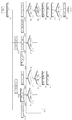
도 4는 본 발명의 실시예에 따른 가스 난방기의 제어 방법을 간략히 도시한 순서도,
도 5는 본 발명의 실시예에 따른 가스 난방기의 제어 방법을 상세히 도시한 순서도.1 is a perspective view of a gas heater according to an embodiment of the present invention,
2 is a view showing a partial configuration of the gas heater of FIG. 1,
3 is a control block diagram of a gas heater according to an embodiment of the present invention,
4 is a flowchart briefly showing a control method of a gas heater according to an embodiment of the present invention,
5 is a flow chart showing in detail a control method of a gas heater according to an embodiment of the present invention.
본 발명의 이점 및 특징, 그리고 그것들을 달성하는 방법은 첨부되는 도면과 함께 상세하게 후술되어 있는 실시예들을 참조하면 명확해질 것이다. 그러나 본 발명은 이하에서 개시되는 실시예들에 한정되는 것이 아니라 서로 다른 다양한 형태로 구현될 수 있으며, 단지 본 실시예들은 본 발명의 개시가 완전하도록 하고, 본 발명이 속하는 기술분야에서 통상의 지식을 가진 자에게 발명의 범주를 완전하게 알려주기 위해 제공되는 것이며, 본 발명은 청구항의 범주에 의해 정의될 뿐이다. 명세서 전체에 걸쳐 동일 참조 부호는 동일 구성 요소를 지칭한다.Advantages and features of the present invention, and methods for achieving them will be clarified with reference to embodiments described below in detail together with the accompanying drawings. However, the present invention is not limited to the embodiments disclosed below, but may be implemented in various different forms, and only the embodiments allow the disclosure of the present invention to be complete, and common knowledge in the technical field to which the present invention pertains. It is provided to completely inform the person having the scope of the invention, and the present invention is only defined by the scope of the claims. The same reference numerals refer to the same components throughout the specification.
이하, 도 1 및 도 2를 참조하여, 본 발명의 실시예에 따른 가스 난방기를 설명한다.Hereinafter, a gas heater according to an embodiment of the present invention will be described with reference to FIGS. 1 and 2.
도 1은 본 발명의 실시예에 따른 가스 난방기의 사시도이고, 도 2는 도 1의 가스 난방기의 일부 구성을 도시한 도면이다.1 is a perspective view of a gas heater according to an embodiment of the present invention, and FIG. 2 is a view showing a partial configuration of the gas heater of FIG. 1.
가스 난방기(Gas furnace)(1)는 연료가스(R)의 연소 시 발생되는 화염 및 고온의 연소가스(P)와 열교환된 공기를 실내로 공급함으로써, 실내를 난방하는 기기이다.A
도 1에 도시된 바와 같이, 가스 난방기(1)는 매니폴드(8)에 연료가스(R)를 공급하는 가스밸브(7), 매니폴드(8)로부터 배출된 연료가스(R)가 통과하는 버너(9), 버너(9)를 통과한 연료가스(R)와 공기의 혼합기를 점화시키는 점화기(16) 및 상기 혼합기가 연소되어 생성된 연소가스(P)가 열교환기(2)를 거쳐 배기관(5)으로 배출되는 유동을 일으키는 유도팬(4)을 포함한다.As shown in FIG. 1, the
가스밸브(7)를 통해 공급되는 연료가스(R)로는 천연가스를 냉각하여 액화한 액화천연가스(LNG; Liquefied Natural Gas) 또는 석유 정제 공정의 부산물로 얻은 가스를 가압하여 액화한 액화석유가스(LPG; Liquefied Petroleum Gas)를 사용할 수 있다.The fuel gas (R) supplied through the gas valve (7) is liquefied natural gas (LNG; Liquefied Natural Gas) liquefied by cooling natural gas or liquefied petroleum gas liquefied by pressurizing the gas obtained as a by-product of the oil refining process ( LPG; Liquefied Petroleum Gas) may be used.
가스밸브(7)의 개폐에 따라 매니폴드(8)로 연료가스(R)가 공급되거나 차단될 수 있고, 가스밸브(7)의 개방 정도를 조절하여 매니폴드(8)로 연료가스(R)가 공급되는 양을 조절할 수 있다. 이로써, 가스밸브(7)는 가스 난방기(1)의 화력을 조절할 수 있다.Depending on the opening and closing of the
매니폴드(8)는 가스관(미부호)을 매개로 가스밸브(7)와 연결될 수 있다. 매니폴드(8)에는 연료가스(R)를 배출하는 적어도 하나의 배출 포트가 형성될 수 있다.The
매니폴드(8)에 공급된 연료가스(R)는 상기 배출 포트를 거쳐 노즐로 유입될 수 있다. 상기 노즐은 연료가스(R)를 후술하는 버너(9)를 향해 분사할 수 있다.The fuel gas R supplied to the
도 1 및 도 2에 도시된 바와 같이, 버너(9)에는 매니폴드(8)로부터 배출된 연료가스(R)가 유입될 수 있다. 보다 정확히는, 버너(9)의 벤츄리 튜브(15)로 연료가스(R)가 유입될 수 있다. 연료가스(R)는 벤츄리 튜브(15)를 통과하며 공기와 혼합되어 혼합기를 형성할 수 있다.1 and 2, the fuel gas R discharged from the
버너(9) 또는 벤츄리 튜브(15)를 통과한 상기 혼합기는 벤츄리 튜브(15)의 상측에 설치된 점화기(16)(미도시)의 불꽃 점화로 인해 연소될 수 있다. 이 경우, 상기 혼합기는 연소되어 화염 및 고온의 연소가스(P)가 생성될 수 있다.The mixer, which has passed through the
실내에 공급되는 공기를 화염 및 연소가스(P)가 통과하는 열교환기(2) 주위로 통과시킴으로써, 실내를 난방할 수 있다.By passing the air supplied to the room around the heat exchanger 2 through which the flame and combustion gas P pass, the room can be heated.
열교환기(2)는 제1차 열교환기와, 제2차 열교환기로 구성될 수 있다.The heat exchanger 2 may include a primary heat exchanger and a secondary heat exchanger.
상기 제1차 열교환기는 일단이 버너(9)와 인접하게 배치될 수 있다. 상기 제1차 열교환기의 일단과 반대되는 타단은, 커플링 박스(미도시)에 결합될 수 있다. 상기 제1차 열교환기의 일단으로부터 타단으로 통과하는 연소가스(P)는 상기 커플링 박스를 통해 상기 제2차 열교환기로 전달될 수 있다.One end of the primary heat exchanger may be disposed adjacent to the
상기 제2차 열교환기의 일단은 상기 커플링 박스와 연결될 수 있다. 상기 제1차 열교환기를 통과한 연소가스(P)는 상기 제2차 열교환기의 일단으로 유입되어, 상기 제2차 열교환기를 통과할 수 있다.One end of the second heat exchanger may be connected to the coupling box. The combustion gas P that has passed through the primary heat exchanger may flow into one end of the secondary heat exchanger and pass through the secondary heat exchanger.
상기 제2차 열교환기는 상기 제1차 열교환기를 통과한 연소가스(P)를 상기 제2차 열교환기 주위를 통과하는 공기와 다시 한번 열교환시킬 수 있다.The secondary heat exchanger may once again exchange the combustion gas (P) passing through the primary heat exchanger with air passing around the secondary heat exchanger.
즉, 상기 제2차 열교환기를 통해 상기 제1차 열교환기를 통과한 연소가스(P)의 열에너지를 추가로 이용함으로써, 가스 난방기(1)의 효율이 향상될 수 있다.That is, the efficiency of the
상기 제2차 열교환기를 통과하는 연소가스(P)는 상기 제2차 열교환기 주위를 통과하는 공기와의 열전달 과정을 통해 응축되어, 응축수를 생성할 수 있다. 다시 말해, 연소가스(P)에 포함된 수증기가 응축되어 응축수로 상태 변화할 수 있다.The combustion gas P passing through the second heat exchanger may be condensed through a heat transfer process with air passing around the second heat exchanger to generate condensed water. In other words, the water vapor contained in the combustion gas P may be condensed to change the state to condensed water.
이러한 이유 때문에, 상기 제1차 열교환기 및 상기 제2차 열교환기를 구비한 가스 난방기(1)는, 콘덴싱(condensing) 가스 난방기로도 불리운다.For this reason, the
이때 생성된 응축수는 응축수 수집부(미부호)에 수집될 수 있다. 이를 위해, 상기 제2차 열교환기의 일단과 반대되는 타단은 상기 응축수 수집부의 일측면에 연결될 수 있다.At this time, the generated condensate may be collected in a condensate collection unit (not shown). To this end, the other end opposite to one end of the second heat exchanger may be connected to one side of the condensate collection unit.
상기 응축수 수집부의 타측면에는 후술하는 유도팬(인듀서, inducer)(4)이 결합될 수 있다. 이하에서는, 간략한 설명을 위하여 유도팬(4)이 상기 응축수 수집부에 결합되는 것으로 설명하나, 유도팬(4)은 상기 응축수 수집부가 결합된 마운팅 플레이트에 결합될 수도 있다.An induction fan (inducer, inducer) 4 described later may be coupled to the other side of the condensate collection unit. Hereinafter, for simplicity, the induction fan 4 is described as being coupled to the condensate collection unit, but the induction fan 4 may be coupled to the mounting plate to which the condensate collection unit is coupled.
상기 응축수 수집부에는 개구부가 형성될 수 있다. 상기 응축수 수집부에 형성된 개구부를 매개로, 상기 제2차 열교환기의 타단과 유도팬(4)은 서로 연통될 수 있다.An opening may be formed in the condensate collection unit. The other end of the second heat exchanger and the induction fan 4 may communicate with each other through an opening formed in the condensate collection unit.
즉, 상기 제2차 열교환기의 타단을 통과한 연소가스(P)는, 상기 응축수 수집부에 형성된 개구부를 통해 유도팬(4)으로 빠져나간 후, 배기관(5)을 거쳐 가스 난방기(1)의 외부로 배출될 수 있다.That is, the combustion gas (P) that has passed through the other end of the second heat exchanger, passes through the induction fan 4 through the opening formed in the condensate collection section, and then passes through the exhaust pipe 5 to the
상기 제2차 열교환기에서 생성된 응축수는, 상기 응축수 수집부를 통해 응축수 트랩(6)으로 빠져나간 후, 토출구를 거쳐 가스 난방기(1)의 외부로 배출될 수 있다.The condensate generated in the second heat exchanger may be discharged to the outside of the
이때, 응축수 트랩(6)은 상기 응축수 수집부의 타측면에 결합될 수 있다. 응축수 트랩(6)은 상기 제2차 열교환기에서 생성된 응축수뿐만 아니라, 유도팬(4)에 연결된 배기관(5)에서 생성된 응축수도 함께 수집하여 배출할 수 있다.At this time, the
즉, 상기 제2차 열교환기의 타단에서 미처 응축되지 못한 연소가스(P)가, 배기관(5)을 통과하며 응축되는 경우에 생성되는 응축수도 응축수 트랩(6)으로 수집되어 상기 토출구를 거쳐 가스 난방기(1) 외부로 배출될 수 있다.That is, the condensate generated when the combustion gas P that is not condensed at the other end of the second heat exchanger passes through the exhaust pipe 5 and is condensed is also collected by the
유도팬(4)은 상기 응축수 수집부에 형성된 개구부를 매개로, 상기 제2차 열교환기의 타단과 연통될 수 있다.The induction fan 4 may communicate with the other end of the secondary heat exchanger through an opening formed in the condensate collection unit.
유도팬(4)의 일단은 상기 응축수 수집부의 타측면에 결합되며, 유도팬(4)의 타단은 배기관(5)에 결합될 수 있다.One end of the induction fan 4 is coupled to the other side of the condensate collection unit, the other end of the induction fan 4 may be coupled to the exhaust pipe (5).
유도팬(4)은 연소가스(P)가 상기 제1차 열교환기, 상기 커플링 박스 및 상기 제2차 열교환기를 통과하여, 배기관(5)으로 배출되는 유동을 일으킬 수 있다. 이 점에서, 유도팬(4)은 IDM(Induced Draft Motor)으로 이해될 수 있다.The induction fan 4 may cause a flow through which the combustion gas P passes through the primary heat exchanger, the coupling box, and the secondary heat exchanger, and is discharged to the exhaust pipe 5. In this regard, the induction fan 4 can be understood as an IDM (Induced Draft Motor).
가스 난방기용 송풍팬(블로어, blower)(3)은 가스 난방기(1)의 하부에 위치할 수 있다. 실내에 공급되는 공기는, 송풍팬(3)에 의하여 가스 난방기(1)의 하부로부터 상부로 이동할 수 있다. 이 점에서, 송풍팬(3)은 IBM(Indoor Blower Motor)으로 이해될 수 있다.The blower fan (blower, blower) 3 for the gas heater may be located under the
송풍팬(3)은 열교환기(2) 주위로 공기를 통과시킬 수 있다.The blowing
송풍팬(3)에 의하여 열교환기(2) 주위를 통과하는 공기는, 열교환기(2)를 매개로 고온의 연소가스(P)로부터 열에너지를 전달 받아 온도가 상승될 수 있다. 상기 온도가 상승된 공기가 실내에 공급됨으로써, 실내가 난방될 수 있다.The air passing around the heat exchanger 2 by the blowing
가스 난방기(1)는 케이스(미부호)를 포함할 수 있다. 상기한 가스 난방기(1)의 구성들은 상기 케이스 내부에 수용될 수 있다. 상기 케이스 하부에는 송풍팬(3)과 인접한 측면에 하부측 개구부(미부호)가 형성될 수 있다. 상기 하부측 개구부를 통해 열교환기(2) 주위를 통과하는 공기가 상기 케이스 내부로 유입될 수 있다.The
상기 케이스 상부에는, 배기관(5)이 관통하는 배기관용 개구부(미부호)가 형성될 수 있으나, 위치가 이에 한정되는 것은 아니다.The upper portion of the case may be formed with an opening (unsigned) for the exhaust pipe through which the exhaust pipe 5 passes, but the position is not limited thereto.
상기 케이스 상부에는, 열교환기(2) 상측과 인접한 측면에 상부측 개구부(미부호)가 형성될 수 있다. 상기 상부측 개구부를 통해 열교환기(2) 주위를 통과하며 온도가 상승한 공기가 상기 케이스 외부로 배출되어 실내로 공급될 수 있다.An upper side opening (unsigned) may be formed on a side of the case adjacent to the upper side of the heat exchanger 2. Air passing through the heat exchanger 2 through the upper side opening and the temperature rises may be discharged outside the case and supplied to the room.
상기 하부측 개구부 및 상기 상부측 개구부에는, 난방 대상 공간인 실내 공간과 가스 난방기(1)를 연통시키는 덕트(미부호)가 설치될 수 있다.The lower side opening and the upper side opening may be provided with a duct (unsigned) communicating the indoor space, which is a space to be heated, with the
상기 하부측 개구부와 이에 설치되는 상기 덕트 사이에는 공기에 존재하는 먼지 등의 이물질을 걸러내는 필터(filter)(미도시)가 설치될 수 있다.A filter (not shown) may be installed between the lower side opening and the duct installed in the filter to filter out foreign substances such as dust present in the air.
상기한 대로, 상기 제2차 열교환기는 상기 제1차 열교환기를 통과한 연소가스(P)의 열에너지를 추가로 이용하는 구성이므로, 상기 제1차 열교환기만을 적용한 가스 난방기에 비하여, 상기 제1차 열교환기 및 상기 제2차 열교환기를 적용한 가스 난방기의 효율이 우수할 것임을 쉽게 이해할 수 있다.As described above, since the second heat exchanger is configured to additionally use the thermal energy of the combustion gas P that has passed through the first heat exchanger, compared to the gas heater that applies only the first heat exchanger, the first heat exchanger It can be easily understood that the efficiency of the gas heater applied to the group and the second heat exchanger will be excellent.
본 발명의 실시예에 따른 가스 난방기의 제어 방법은 상기 제1차 열교환기만 적용한 가스 난방기뿐만 아니라, 상기 제1차 열교환기 및 상기 제2차 열교환기를 적용한 가스 난방기에 적용할 수 있다.The control method of the gas heater according to the embodiment of the present invention can be applied to the gas heater to which the primary heat exchanger and the secondary heat exchanger are applied, as well as the gas heater to which only the primary heat exchanger is applied.
상기한 대로, 가스밸브(7)의 개폐 또는 개방 정도에 따라, 매니폴드(8) 또는 벤츄리 튜브(15)로 공급되는 연료가스(R)의 양이 결정되므로, 가스 난방기(1)의 난방 운전 신호 또는 화력 조절 신호와 같은 제어 신호에 따르지 않고 가스밸브(7)가 오작동되면 사용자가 원하는 정도로 난방이 되지 않거나, 열교환기(2) 내에 연소되지 않은 연료가스(R)가 가득 쌓이게 되어 가스 폭발할 위험이 생길 수 있다.As described above, the amount of the fuel gas R supplied to the
이에, 가스밸브(7)의 오작동을 감지하고, 이를 사용자에게 알려 적절한 안전상의 조치를 취하도록 유도함과 아울러, 안전성이 확보될 때까지 조건부적으로 시스템을 운용하는 것이 필요하다. 본 발명은 상기한 과제를 해결하기 위해 안출되었다.Accordingly, it is necessary to detect the malfunction of the
이하, 도 1 내지 도 5를 참조하여, 본 발명의 실시예에 따른 가스 난방기의 제어 방법을 보다 상세하게 설명한다.Hereinafter, a control method of a gas heater according to an embodiment of the present invention will be described in more detail with reference to FIGS. 1 to 5.
도 3은 본 발명의 실시예에 다른 가스 난방기의 제어 블록도, 도 4는 본 발명의 실시예에 따른 가스 난방기의 제어 방법을 간략히 도시한 순서도, 도 5는 본 발명의 실시예에 따른 가스 난방기의 제어 방법을 상세히 도시한 순서도이다.3 is a control block diagram of a gas heater according to an embodiment of the present invention, FIG. 4 is a flowchart briefly showing a control method of a gas heater according to an embodiment of the present invention, and FIG. 5 is a gas heater according to an embodiment of the present invention It is a flow chart showing the control method in detail.
도 3에 도시된 바와 같이, 후술하는 본 발명의 실시예에 따른 가스 난방기의 제어 방법을 구성하는 각각의 단계들은, 가스 난방기(1)에 구비된 제어부(18)를 통해 수행될 수 있다.As shown in FIG. 3, each of the steps constituting the control method of the gas heater according to the embodiment of the present invention described below may be performed through the
제어부(18)는 ASICs(application specific integrated circuits), DSPs(digital signal processors), DSPDs(digital signal processing devices), PLDs(programmable logic devices), FPGAs(field programmable gate arrays), 프로세서(processors), 제어기(controllers), 마이크로 컨트롤러(micro-controllers), 마이크로 프로세서(microprocessors), 기타 기능 수행을 위한 전기적 유닛 중 적어도 하나를 이용하여 구현될 수 있다.The
후술하는 본 발명의 실시예에 따른 가스 난방기의 제어 방법은 가스 난방기(1)의 전원을 ON하는 단계(S1)가 실행된 후이자, 가스 난방기(1)의 전원 OFF하는 단계(S9)가 실행되기 전에 수행될 수 있다.The control method of the gas heater according to an embodiment of the present invention described later is after the step of turning on the power of the gas heater 1 (S1), and the step of turning off the power of the gas heater 1 (S9) is executed. Before it can be done.
가스 난방기(1)의 전원이 ON된 상태에서, 가스 난방기(1)는 운전 중이거나 미운전 중일 수 있다.In the state where the power of the
여기서, 가스 난방기(1)가 운전 중이라는 것은, 가스밸브(7)가 개방되어 매니폴드(8) 및 벤츄리 튜브(15)로 연료가스(R)가 유입되고, 상기 유입된 연료가스(R)가 연소되어 생성된 화염 및 고온의 연소가스(P)가 열교환기(2) 내부를 통과하고 있는 경우를 말한다.Here, that the
반대로, 가스 난방기(1)가 미운전 중이라는 것은, 가스밸브(7)가 폐쇄되어 매니폴드(8) 및 벤츄리 튜브(15)로의 연료가스(R)의 유입이 차단되고 있는 경우를 말한다.Conversely, that the
본 발명은 난방 신호(R1)에 따라 난방 운전되거나 정지 신호(R2)에 따라 난방 정지되는 가스 난방기의 제어 방법에 관한 것이다. 여기서, 난방 신호(R1)는 상기한 가스 난방기(1)의 운전 상태로의 진입을 명령하는 신호이고, 정지 신호(R2)는 상기한 가스 난방기(1)의 미운전 상태로의 진입을 명령하는 신호이다.The present invention relates to a control method of a gas heater that is operated to be heated according to the heating signal R1 or stopped to be heated according to the stop signal R2. Here, the heating signal R1 is a signal instructing the
도 4 및 도 5에 도시된 바와 같이, 본 발명의 실시예에 따른 가스 난방기의 제어 방법은 신호 수신 단계(S10), 가스밸브 개폐 명령 단계(S40, S60), 정상 작동 여부 감지 단계(S100), 정상 작동 여부 표시 단계를 포함한다.4 and 5, the control method of the gas heater according to the embodiment of the present invention is a signal receiving step (S10), gas valve opening and closing command steps (S40, S60), normal operation detection step (S100) In addition, it includes a step of indicating whether or not the normal operation.
신호 수신 단계(S10)는 난방 신호(R1) 및 정지 신호(R2) 중 어느 하나를 수신하는 단계이다. 신호 수신 단계(S10)는 난방 신호(R1)를 수신하는 단계(S11)와, 정지 신호(R2)를 수신하는 단계(S12)를 포함할 수 있다.The signal receiving step S10 is a step of receiving one of the heating signal R1 and the stop signal R2. The signal receiving step S10 may include a step S11 of receiving a heating signal R1 and a step S12 of receiving a stop signal R2.
난방 신호(R1) 및 정지 신호(R2)는 난방 대상 공간인 실내에 설치된 써모스탯(thermostat)(20)으로부터 가스 난방기(1)에 발령된 신호일 수 있다. 써모스탯(20)에는 실내 온도(Tr)를 측정할 수 있는 써모커플(thermocouple)이 내장될 수 있고, 실내 온도(Tr) 및 난방 설정 온도(Th)를 재실자에게 표시해주는 온도 표시부(21)와, 재실자가 난방 설정 온도(Th)를 조절할 수 있는 온도 조절부(22)와, 후술하는 상태 알림부(23)를 포함할 수 있다.The heating signal R1 and the stop signal R2 may be signals issued to the
실내 온도(Tr)와 난방 설정 온도(Th)의 차이에 따라, 가스 난방기(1)의 화력을 조절하는 것이 필요하므로, 난방 신호(R1)는 약난방 신호와 강난방 신호 등으로 세분화될 수 있다. 이 경우, 난방 신호(R1)의 난방 세기에 대응해 가스밸브(7)의 개방 정도가 결정되어 가스 난방기(1)의 화력을 조절할 수 있다.According to the difference between the indoor temperature Tr and the heating set temperature Th, it is necessary to adjust the thermal power of the
이 경우 써모스탯(20)은 실내 온도(Tr)와 난방 설정 온도(Th)의 차이가 소정값 미만이면 가스 난방기(1)에 상기 약난방 신호를 발령하고, 상기 차이가 상기 소정값 이상이면 가스 난방기(1)에 상기 강난방 신호를 발령할 수 있다.In this case, the
한편, 본 발명의 실시예에 있어서는 써모스탯(20)이 실내 온도(Tr)와 난방 설정 온도(Th)를 비교하여 가스 난방기(1)에 상기 약난방 신호 및 강난방 신호 중 어느 하나를 발령하나, 이에 국한되지 않고 수동 입력을 통해 재실자가 직접 가스 난방기(1)에 상기 약난방 신호 및 강난방 신호 중 어느 하나를 발령할 수도 있다.On the other hand, in the embodiment of the present invention, the
<난방 신호(R1)를 수신하는 경우><When receiving a heating signal (R1)>
S11 단계에서 난방 신호(R1)가 수신되면, 유도팬(4)이 동작되도록 신호를 발령하는 단계(S20)가 수행될 수 있다.When the heating signal R1 is received in step S11, a step S20 of issuing a signal to operate the induction fan 4 may be performed.
후술하는 점화기(16)의 점화, 가스밸브(7)의 개방 동작에 앞서, S20 단계를 통해 유도팬(4)을 먼저 동작시키는 것은, 이전 가스 난방기(1)의 운전에 따라 열교환기(2) 내부에 잔류하고 있는 가스, 이물질 등을 배기관(5)을 통해 외부로 배출시킴으로써 가스 폭발 등의 안전상의 위험을 최소화하기 위함이다.Prior to the ignition of the
S20 단계 이후에, 점화기(16)를 동작시키는 단계(S30)가 수행될 수 있다. 여기서 점화기(16)의 동작은, 이후에 벤츄리 튜브(15)를 통과한 상기 혼합기의 연소를 위해 불꽃 점화를 일으키는 것을 말한다.After step S20, step S30 of operating the
이때, 점화기(16)의 동작에 따른 점화로 인해 상기 혼합기가 연소되면 화염 및 연소가스(P)가 생성되고, 벤츄리 튜브(15)의 상측에 설치된 화염 감지부(17)를 통해 화염을 감지함으로써 상기한 연소 반응이 잘 이루어졌는지를 알 수 있다.At this time, when the mixer is burned due to ignition according to the operation of the
화염 감지부(17)에서 화염을 감지하는 수단으로는 일반적인 기술이 적용될 수 있으므로, 본 명세서에서는 자세한 설명을 생략한다.As a means for detecting the flame in the
한편, 본 발명은 가스밸브(7) 및 유량센서(14)의 이상 점검을 통한 가스 난방기(1)의 안전성 확보에 주안점이 있으므로, 점화기(16)의 오작동 여부는 본 발명에서 특별히 문제 삼지 않는다.On the other hand, the present invention has a main focus on securing the safety of the
즉, 난방 신호(R1) 또는 정지 신호(R2)가 수신됨에 따라 수행되는 상기 또는 후술하는 단계들에서는, 점화기(16)는 정상적으로 동작되거나 정지되는 것으로 간주되고, 나아가 난방 신호(R1)에서는 화염 감지부(17)에서 화염이 감지된 것을 전제로 하고, 정지 신호(R2)에서는 화염 감지부(17)에서 화염이 미감지된 것을 전제로 한다.That is, in the above or below steps performed when the heating signal R1 or the stop signal R2 is received, the
다만, 본 발명이 점화기(16)의 오작동 여부까지 감지하여 재실자에게 알리는 발명에도 적용될 수 있음은 물론이고, 단지 본 발명의 사상을 명확히 설명하기 위해 점화기(16)의 오작동 여부를 특별히 문제 삼지 않는 것임을 다시 한번 밝혀둔다.However, the present invention can be applied not only to the invention that detects whether the
S30 단계 이후에, 가스밸브 개방 명령 단계(S40)가 수행될 수 있다. 가스밸브 개방 명령 단계(S40)는 가스밸브(7)가 개방되도록 신호를 발령하는 단계이다. S40 단계에서 발령되는 신호는 상기한 약난방 및 강난방 신호를 포함할 수 있고, 제어 설계에 따라 보다 세분화하여 가스 난방기(1)의 화력을 단계적으로 조절하는 신호일 수 있다.After step S30, a gas valve opening command step S40 may be performed. The gas valve opening command step S40 is a step of issuing a signal so that the
먼저 S40 단계에서 발령된 신호에 대응해 가스밸브(7)의 오작동 여부를 감지하고 작동 이상을 외부에 표시하는 방법을 설명하고, 이후에 가스밸브(7)가 개방된 정도가 S40 단계에서 발령된 신호에 대응하는지를 모니터링하는 방법을 설명하도록 한다.First, in response to the signal issued in step S40, a method of detecting whether the
S40 단계 이후에, 정상 작동 여부 감지 단계(S100)가 수행될 수 있다. 보다 구체적으로, S40 단계 이후에, 가스밸브(7) 개폐 여부를 감지하는 단계(S110)와, 매니폴드(8) 내 연료가스(R)의 유량을 감지하는 단계(S120)가 수행될 수 있다.After step S40, a normal operation detection step S100 may be performed. More specifically, after step S40, the step of detecting whether the
본 발명의 실시예에서는 S110 단계 이후에 S120 단계가 수행되나, 동시에 수행되거나 역순으로 수행되는 것도 가능하다.In the embodiment of the present invention, step S120 is performed after step S110, but it is also possible to perform simultaneously or in the reverse order.
S110 단계는 소정의 압력, 유량 센서를 통해 가스밸브(7)의 개폐 여부를 감지하는 단계일 수 있다. 상기 센서로는 밸브의 개방, 폐쇄를 감지할 수 있는 일반적인 센서가 적용될 수 있으므르, 본 명세서에서는 자세한 설명을 생략한다.Step S110 may be a step of detecting whether the
도 2에 도시된 바와 같이, 본 발명의 실시예에 따른 가스밸브(7)는 솔레노이드 밸브(11)와 스탭 모터(12)를 포함할 수 있다.2, the
솔레노이드 밸브(11)는 솔레노이드 코일에 소정의 전류가 흘러 자기장이 형성되면, 상기 솔레노이드 코일 내부에 위치한 플런저가 상기 자기장의 방향으로 이동되는 원리를 이용한 밸브로서, 관로를 개방 또는 폐쇄할 수 있는 밸브이다.The
솔레노이드 밸브(11)와 스탭 모터(12)를 조합한 가스밸브(7)는 상기 관로를 개방 또는 폐쇄할 수 있을 뿐만 아니라, 상기 관로의 개방 정도를 조절할 수 있는 리니어 밸브로 이해될 수 있고, 가스 난방기(1)의 화력을 단계적으로 조절할 수 있다.The
매니폴드(8) 내 연료가스(R)의 유량을 감지하는 단계(S120)는 유량센서(14)를 통해 매니폴드(8) 내 연료가스(R)의 유량을 감지하는 단계일 수 있고, 유량센서(14)는 매니폴드(8)에 설치될 수 있다.The step (S120) of detecting the flow rate of the fuel gas R in the
S120 단계는 S110 단계에서 가스밸브(7)가 개방된 것으로 감지되면 수행되는 매니폴드(8) 내 연료가스(R)의 유량을 감지하는 단계(S121)와, S110 단계에서 가스밸브(7)가 폐쇄된 것으로 감지되면 수행되는 매니폴드(8) 내 연료가스(R)의 유량을 감지하는 단계(S122)를 포함할 수 있다.Step S120 is a step (S121) of detecting the flow rate of the fuel gas (R) in the manifold (8) is performed when the gas valve (7) is detected in step S110, and the gas valve (7) in step S110 It may include the step (S122) of sensing the flow rate of the fuel gas (R) in the manifold (8) is performed when it is detected as closed.
즉, 본 발명은 가스밸브(7)의 개폐 여부를 감지할 수 있는 수단 외에도 매니폴드(8)에 설치된 유량센서(14)를 통해 가스밸브(7)의 오작동을 감지할 수 있다는 데 특징이 있고, 이로써 가스 난방기(1)의 안전성을 보다 향상시킬 수 있다.That is, the present invention is characterized in that it is possible to detect a malfunction of the
정상 작동 여부 감지 단계(S100) 이후에, 정상 작동 여부 표시 단계(S200)가 수행될 수 있다. 정상 작동 여부 표시 단계(S200)는 S100 단계에서 감지된 정보를 토대로, 난방 운전의 정상 작동 여부를 표시하는 단계일 수 있고, 보다 구체적으로 설명하면 다음과 같다.After the normal operation detection step (S100), a normal operation display operation (S200) may be performed. The normal operation display step (S200) may be a step of displaying the normal operation of the heating operation based on the information detected in the step S100, and will be described in more detail as follows.
정상 작동 여부 표시 단계(S200)는 S110 단계에서 가스밸브(7)가 개방된 것으로 감지되고, S121 단계에서 매니폴드(8) 내 연료가스(R)의 유량이 '0'을 초과한 것으로 감지되면, 상기 난방 운전의 정상 작동을 표시하는 단계(S210)를 포함할 수 있다.If the normal operation or not indication step (S200) is detected in step S110, the
정상 작동 여부 표시 단계(S200)는 S110 단계에서 가스밸브(7)가 개방된 것으로 감지되고, S121 단계에서 매니폴드(8) 내 연료가스(R)의 유량이 ‘0’인 것으로 감지되면, 유량센서(14)의 이상을 표시하는 단계(S220)를 포함할 수 있다.If the normal operation or not indication step (S200) is detected in step S110, the
정상 작동 여부 표시 단계(S200)는 S110 단계에서 가스밸브(7)가 폐쇄된 것으로 감지되고, S122 단계에서 매니폴드(8) 내 연료가스(R)의 유량이 ‘0’을 초과한 것으로 감지되면, 가스밸브(7)의 이상을 표시하는 단계(S230)를 포함할 수 있다.If the normal operation or not indication step (S200) is detected in step S110, the
정상 작동 여부 표시 단계(S200)는 S110 단계에서 가스밸브(7)가 폐쇄된 것으로 감지되고, S122 단계에서 매니폴드(8) 내 연료가스(R)의 유량이 ‘0’인 것으로 감지되면, 가스밸브(7) 및 유량센서(14)의 이상을 표시하는 단계(S240)를 포함할 수 있다.If the normal operation or not indication step (S200) is detected in step S110, the
S220, S230, S240 단계 각각의 이후에는, 비정상 운전 정지 단계(S400)가 수행될 수 있다. 비정상 운전 정지 단계(S400)는 가스밸브(7) 및 유량센서(14) 중 적어도 하나에 이상이 있는 경우, 상기 난방 운전을 정지시키는 단계이다.After each of the steps S220, S230, and S240, an abnormal operation stop step S400 may be performed. The abnormal operation stop step S400 is a step of stopping the heating operation when there is an abnormality in at least one of the
S400 단계는 점화기(16)의 동작을 정지시키고, 가스밸브(7)가 폐쇄되도록 하되, 유도팬(4)의 동작은 유지되도록 하는 단계일 수 있다.In step S400, the operation of the
즉, S400 단계는 가스밸브(7)를 폐쇄하여 연료가스(R)의 공급을 차단하고, 점화기(16)의 동작을 정지시켜 연료가스(R)의 연소를 중지시키면서, 유도팬(4)은 계속 동작시켜 열교환기(2) 내부에 잔류하고 있는 가스를 배기관(5)을 통해 외부로 배출시키는 단계일 수 있다. 이로써, 가스밸브(7) 및 유량센서(14)의 이상 작동으로 인한 가스 폭발 등의 안전상 위험을 제거할 수 있다.That is, in step S400, the
이 경우, 점화기(16)의 동작 정지는 가스밸브(7) 및 유량센서(14)의 점검이 완료되어야 해제 가능할 수 있다. 즉, 가스밸브(7) 및 유량센서(14) 중 적어도 하나에 이상이 있어, 점화기(16)의 동작이 정지된 후에는, 상기 점검이 있기 전에는 난방 신호(R1)가 수신되더라도 점화기(16)가 동작되지 않을 수 있고, 이는 가스 난방기(1)의 안전이 확보되기 전에는 다시 운전되는 것을 방지하기 위함이다.In this case, the operation stop of the
본 발명의 실시예에서는 S220, S230, S240 단계 각각 이후에 S400 단계가 수행되나, 동시에 수행되거나 역순으로 수행되는 것도 가능하다.In the embodiment of the present invention, steps S400, S230, and S240 are performed after each of the steps, but it is also possible to perform simultaneously or in the reverse order.
한편, S40 단계는 가스 난방기(1)의 소정의 필요 화력에 대응하여 가스밸브(7)가 단계적으로 개방되도록 신호를 발령하는 단계일 수 있고, 상기 신호에 따라 가스밸브(7)의 개방 정도가 조절될 수 있다.Meanwhile, step S40 may be a step of issuing a signal such that the
이 경우, S121 단계에서 감지된 매니폴드(8) 내 연료가스(R)의 유량이, S40 단계에서 발령된 신호에 대응하는지를 모니터링하는 단계(S600)를 더 포함할 수 있다.In this case, the step (S600) of monitoring whether the flow rate of the fuel gas (R) in the
즉, 실제로 가스밸브(7)의 개방 정도가, S40 단계에서 발령된 신호에 대응한지를 S121 단계에서 감지된 연료가스(R)의 유량을 통해 확인할 수 있고, 양자가 서로 대응하는 경우(즉, 정상 작동) 또는 대응하지 않는 경우(즉, 비정상 작동) 각각을 써모스탯의 상태 알림부(23)를 통해 재실자에게 알릴 수 있다.That is, in fact, it is possible to check whether the opening degree of the
<정지 신호(R2)를 수신하는 경우><When a stop signal (R2) is received>
S12 단계에서 정지 신호(R2)가 수신되면, 점화기(16)의 동작을 정지시키는 단계(S50)가 수행될 수 있다. 여기서 점화기(16)의 동작 정지는, 상기한 점화기(16)에 의한 불꽃 점화가 일어나지 않도록 하는 것을 말한다.When the stop signal R2 is received in step S12, step S50 of stopping the operation of the
이때, 화염 감지부(17)를 통해 화염이 생성되지 않았음을 감지함으로써 상기 연소 반응이 이루어지지 않고 있다는 것을 알 수 있다.At this time, it can be seen that the combustion reaction is not achieved by detecting that no flame is generated through the
S50 단계 이후에, 가스밸브 폐쇄 명령 단계(S60)가 수행될 수 있다. 가스밸브 폐쇄 명령 단계(S60)는 가스밸브(7)가 폐쇄되도록 신호를 발령하는 단계이다.After step S50, the gas valve closing command step S60 may be performed. The gas valve closing command step S60 is a step of issuing a signal so that the
S60 단계 이후에, 정상 작동 여부 감지 단계(S100)가 수행될 수 있다. 보다 구체적으로, S60 단계 이후에, 가스밸브(7)의 개폐 여부를 감지하는 단계(S130)와, 매니폴드(8) 내 연료가스(R)의 유량을 감지하는 단계(S140)가 수행될 수 있다.After step S60, a normal operation detection step (S100) may be performed. More specifically, after step S60, the step of detecting whether the
본 발명의 실시예에서는 S130 단계 이후에 S140 단계가 수행되나, 동시에 수행되거나 역순으로 수행되는 것도 가능하다.In the embodiment of the present invention, step S140 is performed after step S130, but it is also possible to perform simultaneously or in the reverse order.
S130 단계는 소정의 압력, 유량 센서를 통해 가스밸브(7)의 개폐 여부를 감지하는 단계일 수 있다. 상기 센서로는 밸브의 개방, 폐쇄를 감지할 수 있는 일반적인 센서가 적용될 수 있으므르, 본 명세서에서는 자세한 설명을 생략한다.Step S130 may be a step of detecting whether the
S130 단계는 가스밸브(7)의 개방 상태가 소정 시간이 경과하도록 지속되면 가스밸브(7)가 개방된 것으로 감지하는 단계(S131, S132)일 수 있다.Step S130 may be a step (S131, S132) of detecting that the
일 예로써, 상기 소정 시간이 10초인 경우, 가스밸브(7)의 개방 상태에서의 지속 시간(t)이 8초이고 그후에는 폐쇄 상태이면 "가스밸브(7)가 폐쇄된 것으로 감지"하고, 가스밸브(7)의 개방 상태에서의 지속 시간(t)이 10초를 경과하면 "가스밸브(7)가 개방된 것으로 감지"한다.As an example, when the predetermined time is 10 seconds, if the duration t in the open state of the
S130 단계에서 가스밸브(7)의 개방 상태를 상기 소정 시간을 기준으로 판별하는 이유는, S60 단계에서 발령된 신호에 따라 실제로 가스밸브(7)가 폐쇄되기 까지의 필요한 시간을 고려한 것으로 이해될 수 있다.The reason for determining the open state of the
매니폴드(8) 내 연료가스(R)의 유량을 감지하는 단계(S140)는 유량센서(14)를 통해 매니폴드(8) 내 연료가스(R)의 유량을 감지하는 단계일 수 있고, 유량센서(14)는 매니폴드(8)에 설치될 수 있다.The step (S140) of detecting the flow rate of the fuel gas (R) in the manifold (8) may be a step of sensing the flow rate of the fuel gas (R) in the manifold (8) through the flow sensor (14), The
즉, 본 발명은 가스밸브(7)의 개폐 여부를 감지할 수 있는 수단 외에도 매니폴드(8)에 설치된 유량센서(14)를 통해 가스밸브(7)의 오작동을 감지할 수 있다는 데 특징이 있고, 이로써 난방 정지 중임에도 열교환기(2) 내부로 연료가스(R)가 공급되어 이후에 난방 운전을 위한 점화 시 가스 폭발되는 사고를 미연에 방지할 수 있다.That is, the present invention is characterized in that it is possible to detect a malfunction of the
한편, 도 5에 도시된 바와 같이 본 발명의 실시예에서는, S130 단계에서 가스밸브(7)가 폐쇄된 것으로 감지되는 경우에만 S140 단계가 수행되는 것으로 설명하나, 이와 달리 S130 단계에서 가스밸브(7)가 개방된 것으로 감지되는 경우에도 매니폴드(8) 내 연료가스(R)의 유량을 감지하는 단계가 수행될 수도 있다.On the other hand, in the embodiment of the present invention as shown in Figure 5, it is described that the step S140 is performed only when it is detected that the
정상 작동 여부 감지 단계(S100) 이후에, 정상 작동 여부 표시 단계(S300)가 수행될 수 있다. 정상 작동 여부 표시 단계(S300)는 S100 단계에서 감지된 정보를 토대로, 난방 정지의 정상 작동 여부를 표시하는 단계일 수 있고, 보다 구체적으로 설명하면 다음과 같다.After the normal operation detection step S100, the normal operation display step S300 may be performed. The normal operation display step (S300) may be a step of displaying the normal operation of the heating stop, based on the information detected in step S100, and will be described in more detail as follows.
정상 작동 여부 표시 단계(S300)는 S130 단계에서 가스밸브(7)가 폐쇄된 것으로 감지되고, S140 단계에서 매니폴드(8) 내 연료가스(R)의 유량이 '0'인 것으로 감지되면, 난방 정지의 정상 작동을 표시하는 단계(S310)를 포함할 수 있다.In operation S300, if the
정상 작동 여부 표시 단계(S300)는 S130 단계에서 가스밸브(7)가 폐쇄된 것으로 감지되고, S140 단계에서 매니폴드(8) 내 연료가스(R)의 유량이 ‘0’을 초과한 것으로 감지되면, 가스밸브(7) 또는 유량센서(14)의 이상을 표시하는 단계(S320)를 포함할 수 있다.If the normal operation or not indication step (S300) is detected in step S130, the
S320 단계에서 가스밸브(7) '또는' 유량센서(14)의 이상이 표시되는 이유를 설명하면, S50 단계에서 점화기(16)의 동작이 정지되어 화염이 생성되지 않는 상황에서는, 가스밸브(7) 및 유량센서(14) 중 어느 것이 제대로 작동하는지를 정확히 가려내기 어려우므로 보수적으로 가스밸브(7) '또는' 유량센서(14)의 이상으로 표시하는 것으로 이해될 수 있다.When explaining the reason why the abnormality of the gas valve 7'or' the
즉, S130 단계에서 가스밸브(7)가 폐쇄된 것으로 감지되고, S140 단계에서 매니폴드(8) 내 연료가스(R)의 유량이 ‘0’을 초과한 것으로 감지되어 정보가 서로 모순되는 상황에서, 가스밸브(7) 및 유량센서(14) 중, (i) 유량센서(14)만이 정상 작동하는 경우(즉, 가스밸브(7)는 실제로 개방 상태), (ii) 가스밸브(7)만이 정상 작동하는 경우(즉, 매니폴드(8) 내 연료가스(R)의 실제 유량은 '0') 모두 가능하나, 양자 모두 화염 감지부(17)에서 화염이 감지되지 않는다는 점에서는 차이가 없어 실제 어떤 경우인지를 파악하기 어려우므로 S320 단계는 "가스밸브(7) '또는' 유량센서(14)의 이상으로 표시"하는 것이 바람직할 수 있다.That is, in step S130, it is sensed that the
정상 작동 여부 표시 단계(S300)는 S130 단계에서 가스밸브(7)가 개방된 것으로 감지되면, 가스밸브(7) 이상을 표시하는 단계(S330)를 포함할 수 있다.In operation S130, if the
S320, S330 단계 각각 이후에는, 비정상 정지 단계(S500)가 수행될 수 있다. 비정상 정지 단계(S500)는 가스밸브(7) 및 유량센서(14) 중 적어도 하나에 이상이 있는 경우, 유도팬(4)을 동작시킨채 난방 운전을 정지시키는 단계이다.After each of steps S320 and S330, an abnormal stop step S500 may be performed. The abnormal stop step S500 is a step of stopping the heating operation while operating the induction fan 4 when there is an abnormality in at least one of the
즉, S500 단계는 가스밸브(7) 및 유량센서(14) 중 적어도 하나에 이상이 있어 S60 단계에서의 가스밸브 폐쇄 명령 신호에도 불구하고 열교환기(2) 내부로 연료가스(R)가 공급되고 있으므로, 유도팬(4)을 동작시켜 열교환기(2) 내부에 잔류하고 있는 가스를 배기관(5)을 통해 외부로 배출시키는 단계일 수 있다. 이로써, 가스밸브(7) 및 유량센서(14)의 이상 작동으로 인한 가스 폭발 등의 안전상 위험을 제거할 수 있다.That is, in step S500, there is an abnormality in at least one of the
이 경우, S500 단계는 정지 신호(R2)가 수신되기 전에 난방 운전 중이어서 유도팬(4)이 동작되고 있던 경우라면 유도팬(4)의 동작이 유지되도록 하고, 정지 신호(R2)가 수신되기 전에도 난방 정지 중이어서 유도팬(4)이 동작되고 있지 않던 경우라면 유도팬(4)의 동작이 개시되도록 하는 단계일 수 있다.In this case, in step S500, when the induction fan 4 is operating because the heating operation is in operation before the stop signal R2 is received, the operation of the induction fan 4 is maintained, and the stop signal R2 is received. If the induction fan 4 was not operating because the heating was stopped before, it may be a step of starting the operation of the induction fan 4.
또한, S50 단계에서 수행된 점화기(16)의 동작 정지는 가스밸브(7) 및 유량센서(14)의 점검이 완료되어야 해제될 수 있다. 즉, 가스밸브(7) 및 유량센서(14) 중 적어도 하나에 이상이 있는 경우에는, 상기 점검이 있기 전에는 난방 신호(R1)가 수신되더라도 점화기(16)가 동작되지 않을 수 있고, 이는 가스 난방기(1)의 안전이 확보되기 전에는 다시 운전되는 것을 방지하기 위함이다.In addition, the operation stop of the
본 발명의 실시예에서는 S320, S330 단계 각각 이후에 S500 단계가 수행되나, 동시에 수행되거나 역순으로 수행되는 것도 가능하다.In the embodiment of the present invention, steps S320 and S330 are performed after steps S500, respectively, but it is also possible to perform simultaneously or in the reverse order.
이상, 본 발명의 실시예에 따른 드라이어를 첨부도면을 참조하여 설명하였다. 그러나, 본 발명은 상기 실시예에 한정되는 것은 아니고, 본 발명의 요지를 벗어나지 않는 범위 내에서 본 발명이 속하는 기술분야에서 통상의 지식을 가진자가 예측할 수 있는 다양한 변형이나 균등한 범위내에서의 실시가 가능함은 물론이다.The dryer according to the embodiment of the present invention has been described above with reference to the accompanying drawings. However, the present invention is not limited to the above embodiments, and is implemented within various modifications or equivalent ranges predictable by those skilled in the art to which the present invention pertains without departing from the gist of the present invention. Of course it is possible.
1: 가스 난방기
2: 열교환기
3: 송풍팬
4: 유도팬
5: 배기관
6: 응축수 트랩
7: 가스밸브
8: 매니폴드
9: 버너
14: 유량센서
R1: 난방 신호
R2: 정지 신호
S10: 신호 수신 단계
S40: 가스밸브 개방 명령 단계
S60: 가스밸브 폐쇄 명령 단계
S100: 정상 작동 여부 감지 단계
S200, S300: 정상 작동 여부 표시 단계1: gas heater 2: heat exchanger
3: Blowing fan 4: Induction fan
5: exhaust pipe 6: condensate trap
7: Gas valve 8: Manifold
9: Burner 14: Flow sensor
R1: Heating signal R2: Stop signal
S10: Signal receiving step S40: Gas valve opening command step
S60: Gas valve closing command step S100: Normal operation detection step
S200, S300: Normal operation status display step
Claims (17)
(a) 상기 난방 신호 및 정지 신호 중 어느 하나를 수신하는 단계;
(b) 상기 난방 신호가 수신되면, 상기 유도팬이 동작되도록 신호를 발령하는 단계;
(c) 상기 점화기를 동작시키는 단계;
(d) 상기 가스밸브가 개방되도록 신호를 발령하는 단계;
(e) 상기 가스밸브의 개폐 여부를 감지하는 단계;
(f) 상기 매니폴드 내 연료가스의 유량을 감지하는 단계; 및
(g) 상기 (e) 및 (f) 단계에서 감지된 정보를 토대로, 상기 난방 운전의 정상 작동 여부를 표시하는 단계를 포함하는 가스 난방기의 제어 방법.A gas valve supplying fuel gas to the manifold; A burner through which fuel gas discharged from the manifold passes; An igniter that ignites a mixture of fuel gas and air that has passed through the burner; And an induction fan for causing the flow of the combustion gas generated by combustion of the mixer to be discharged to an exhaust pipe through a heat exchanger, and in a control method of a gas heater that is heated to stop according to a heating signal or stops heating according to a stop signal,
(A) receiving any one of the heating signal and the stop signal;
(b) when the heating signal is received, issuing a signal to operate the induction fan;
(c) operating the igniter;
(d) issuing a signal to open the gas valve;
(e) detecting whether the gas valve is opened or closed;
(f) sensing the flow rate of fuel gas in the manifold; And
(g) based on the information detected in steps (e) and (f), the control method of the gas heater comprising the step of displaying whether the heating operation is normal.
상기 (f) 단계는,
상기 매니폴드에 설치된 유량센서를 이용해, 상기 매니폴드 내 연료가스의 유량을 감지하는 단계인 가스 난방기의 제어 방법.According to claim 1,
Step (f) is,
A method of controlling a gas heater, which is a step of sensing a flow rate of fuel gas in the manifold using a flow sensor installed in the manifold.
상기 (g) 단계는,
상기 (e) 단계에서 상기 가스밸브가 개방된 것으로 감지되고, 상기 (f) 단계에서 상기 매니폴드 내 연료가스의 유량이 '0'을 초과한 것으로 감지되면, 상기 난방 운전의 정상 작동을 표시하는 단계를 포함하는 가스 난방기의 제어 방법.According to claim 2,
Step (g) is,
If it is detected in step (e) that the gas valve is open, and in step (f) it is detected that the flow rate of fuel gas in the manifold exceeds '0', indicating normal operation of the heating operation. Method of controlling a gas heater comprising a step.
상기 (g) 단계는,
상기 (e) 단계에서 상기 가스밸브가 개방된 것으로 감지되고, 상기 (f) 단계에서 상기 매니폴드 내 연료가스의 유량이 '0'인 것으로 감지되면, 상기 유량센서의 이상을 표시하는 단계를 포함하는 가스 난방기의 제어 방법.According to claim 3,
Step (g) is,
If it is detected in step (e) that the gas valve is opened, and step (f) detects that the flow rate of the fuel gas in the manifold is '0', the method includes displaying an abnormality in the flow sensor. The control method of the gas heater.
상기 (g) 단계는,
상기 (e) 단계에서 상기 가스밸브가 폐쇄된 것으로 감지되고, 상기 (f) 단계에서 상기 매니폴드 내 연료가스의 유량이 '0'을 초과한 것으로 감지되면, 상기 가스밸브의 이상을 표시하는 단계를 포함하는 가스 난방기의 제어 방법.According to claim 2,
Step (g) is,
If it is detected in step (e) that the gas valve is closed, and in step (f) it is detected that the flow rate of the fuel gas in the manifold exceeds '0', displaying an abnormality of the gas valve. Control method of the gas heater comprising a.
상기 (g) 단계는,
상기 (e) 단계에서 상기 가스밸브가 폐쇄된 것으로 감지되고, 상기 (f) 단계에서 상기 매니폴드 내 연료가스의 유량이 '0'인 것으로 감지되면, 상기 가스밸브 및 유량센서의 이상을 표시하는 단계를 포함하는 가스 난방기의 제어 방법.The method of claim 5,
Step (g) is,
If it is detected in step (e) that the gas valve is closed, and in step (f) it is detected that the flow rate of fuel gas in the manifold is '0', indicating an abnormality in the gas valve and flow sensor. Method of controlling a gas heater comprising a step.
상기 가스밸브 및 유량센서 중 적어도 하나에 이상이 있는 경우,
(h) 상기 점화기의 동작을 정지시키고, 상기 가스밸브가 폐쇄되도록 하되, 상기 유도팬의 동작은 유지되도록 함으로써 상기 난방 운전을 정지시키는 단계를 더 포함하는 가스 난방기의 제어 방법.The method according to any one of claims 4 to 6,
When there is an abnormality in at least one of the gas valve and the flow sensor,
(h) stopping the operation of the igniter, allowing the gas valve to close, and maintaining the operation of the induction fan to stop the heating operation, thereby further controlling the gas heater.
상기 가스밸브 및 유량센서 중 적어도 하나에 이상이 있는 경우,
상기 (h) 단계에서의 상기 점화기의 동작 정지는,
상기 가스밸브 및 유량센서의 점검이 완료되어야 해제 가능한 가스 난방기의 제어 방법.The method of claim 7,
When there is an abnormality in at least one of the gas valve and the flow sensor,
The operation stop of the igniter in the step (h),
Control method of the gas heater that can be released only after the inspection of the gas valve and the flow sensor is completed.
상기 (d) 단계는,
상기 가스 난방기의 소정의 필요 화력에 대응하여 상기 가스밸브가 단계적으로 개방되도록 신호를 발령하는 단계이고,
상기 (f) 단계에서 감지된 상기 매니폴드 내 연료가스의 유량이, 상기 (d) 단계에서 발령된 신호에 대응하는지를 모니터링하는 단계를 더 포함하는 가스 난방기의 제어 방법.According to claim 1,
Step (d) is,
Issuing a signal to open the gas valve step by step in response to a predetermined required thermal power of the gas heater,
And monitoring whether the flow rate of the fuel gas in the manifold detected in step (f) corresponds to the signal issued in step (d).
상기 (a) 단계 이후에,
(i) 상기 정지 신호가 수신되면, 상기 점화기의 동작을 정지시키는 단계;
(j) 상기 가스밸브가 폐쇄되도록 신호를 발령하는 단계;
(k) 상기 가스밸브의 개폐 여부를 감지하는 단계;
(l) 상기 매니폴드 내 연료가스의 유량을 감지하는 단계; 및
(m) 상기 (k) 및 (l) 단계에서 감지된 정보를 토대로, 상기 난방 정지의 정상 작동 여부를 표시하는 단계를 더 포함하는 가스 난방기의 제어 방법.According to claim 1,
After step (a),
(i) when the stop signal is received, stopping the operation of the igniter;
(j) issuing a signal so that the gas valve is closed;
(k) detecting whether the gas valve is opened or closed;
(l) sensing the flow rate of fuel gas in the manifold; And
(m) based on the information detected in steps (k) and (l), the control method of the gas heater further comprising the step of displaying whether the heating stop is normal.
상기 (l) 단계는,
상기 매니폴드에 설치된 유량센서를 이용해, 상기 매니폴드 내 연료가스의 유량을 감지하는 단계인 가스 난방기의 제어 방법.The method of claim 10,
Step (l) is,
A method of controlling a gas heater, which is a step of sensing a flow rate of fuel gas in the manifold using a flow sensor installed in the manifold.
상기 (k) 단계는,
상기 가스밸브의 개방 상태가 소정 시간이 경과하도록 지속되면 상기 가스밸브가 개방된 것으로 감지하는 단계인 가스 난방기의 제어 방법.The method of claim 11,
Step (k) is,
A control method of a gas heater that is a step of detecting that the gas valve is open when the open state of the gas valve continues to pass a predetermined time.
상기 (m) 단계는,
상기 (k) 단계에서 상기 가스밸브가 폐쇄된 것으로 감지되고, 상기 (l) 단계에서 상기 매니폴드 내 연료가스의 유량이 '0'인 것으로 감지되면, 상기 난방 정지의 정상 작동을 표시하는 단계를 포함하는 가스 난방기의 제어 방법.The method of claim 12,
Step (m) is,
If it is detected in step (k) that the gas valve is closed and in step (l) it is detected that the flow rate of the fuel gas in the manifold is '0', displaying the normal operation of the heating stop. Control method of gas heater containing.
상기 (m) 단계는,
상기 (k) 단계에서 상기 가스밸브가 폐쇄된 것으로 감지되고, 상기 (l) 단계에서 상기 매니폴드 내 연료가스의 유량이 '0'을 초과한 것으로 감지되면, 상기 가스밸브 또는 상기 유량센서의 이상을 표시하는 단계를 포함하는 가스 난방기의 제어 방법.The method of claim 13,
Step (m) is,
If it is detected in step (k) that the gas valve is closed, and in step (l) it is detected that the flow rate of the fuel gas in the manifold exceeds '0', the gas valve or the flow sensor is abnormal. Control method of a gas heater comprising the step of displaying.
상기 (m) 단계는,
상기 (k) 단계에서 상기 가스밸브가 개방된 것으로 감지되면, 상기 가스밸브의 이상을 표시하는 단계를 포함하는 가스 난방기의 제어 방법.The method of claim 12,
Step (m) is,
And detecting an abnormality of the gas valve when the gas valve is detected to be open in the step (k).
상기 가스밸브 및 유량센서 중 적어도 하나에 이상이 있는 경우,
(n) 상기 유도팬을 동작시킨채 상기 난방 운전을 정지시키는 단계를 더 포함하는 가스 난방기의 제어 방법.The method of claim 14 or 15,
When there is an abnormality in at least one of the gas valve and the flow sensor,
(n) The control method of the gas heater further comprising the step of stopping the heating operation while operating the induction fan.
상기 가스밸브 및 유량센서 중 적어도 하나에 이상이 있는 경우,
상기 (i) 단계에서의 상기 점화기의 동작 정지는,
상기 가스밸브 및 유량센서의 점검이 완료되어야 해제 가능한 가스 난방기의 제어 방법.The method of claim 16,
When there is an abnormality in at least one of the gas valve and the flow sensor,
The operation stop of the igniter in the step (i),
Control method of the gas heater that can be released only after the inspection of the gas valve and the flow sensor is completed.
Priority Applications (3)
| Application Number | Priority Date | Filing Date | Title |
|---|---|---|---|
| KR1020180169081A KR20200079688A (en) | 2018-12-26 | 2018-12-26 | Control method of gas furnace |
| US16/726,368 US11624504B2 (en) | 2018-12-26 | 2019-12-24 | Control method of gas furnace |
| EP19219774.7A EP3674624B1 (en) | 2018-12-26 | 2019-12-27 | Control method of gas furnace |
Applications Claiming Priority (1)
| Application Number | Priority Date | Filing Date | Title |
|---|---|---|---|
| KR1020180169081A KR20200079688A (en) | 2018-12-26 | 2018-12-26 | Control method of gas furnace |
Publications (1)
| Publication Number | Publication Date |
|---|---|
| KR20200079688A true KR20200079688A (en) | 2020-07-06 |
Family
ID=69055713
Family Applications (1)
| Application Number | Title | Priority Date | Filing Date |
|---|---|---|---|
| KR1020180169081A KR20200079688A (en) | 2018-12-26 | 2018-12-26 | Control method of gas furnace |
Country Status (3)
| Country | Link |
|---|---|
| US (1) | US11624504B2 (en) |
| EP (1) | EP3674624B1 (en) |
| KR (1) | KR20200079688A (en) |
Families Citing this family (2)
| Publication number | Priority date | Publication date | Assignee | Title |
|---|---|---|---|---|
| US20210278143A1 (en) * | 2020-03-09 | 2021-09-09 | Carrier Corporation | System and method for capturing waste heat in an hvac system |
| EP4276356A1 (en) * | 2022-05-09 | 2023-11-15 | BDR Thermea Group B.V. | Method for controlling the operation of a combustion appliance |
Family Cites Families (8)
| Publication number | Priority date | Publication date | Assignee | Title |
|---|---|---|---|---|
| US4348169A (en) | 1978-05-24 | 1982-09-07 | Land Combustion Limited | Control of burners |
| US5997280A (en) * | 1997-11-07 | 1999-12-07 | Maxon Corporation | Intelligent burner control system |
| US6257870B1 (en) | 1998-12-21 | 2001-07-10 | American Standard International Inc. | Gas furnace with variable speed draft inducer |
| US20050155535A1 (en) * | 2004-01-16 | 2005-07-21 | Carrier Corporation | Method and components for draining and trapping |
| US9689569B2 (en) * | 2014-10-30 | 2017-06-27 | Emerson Electric Co. | Universal furnace controller and method of installing same |
| US20190032961A1 (en) * | 2017-07-31 | 2019-01-31 | Ecofurn, LLC | Furnace accessory |
| CN108302537A (en) | 2018-02-01 | 2018-07-20 | 杭州富尔顿热能设备有限公司 | A kind of condensation Hot water units and boiler controller system system |
| US11226053B2 (en) * | 2018-08-28 | 2022-01-18 | Johnson Controls Tyco IP Holdings LLP | Valve assembly with pressure disturbance rejection and fault detection and diagnosis |
-
2018
- 2018-12-26 KR KR1020180169081A patent/KR20200079688A/en not_active Application Discontinuation
-
2019
- 2019-12-24 US US16/726,368 patent/US11624504B2/en active Active
- 2019-12-27 EP EP19219774.7A patent/EP3674624B1/en active Active
Also Published As
| Publication number | Publication date |
|---|---|
| EP3674624B1 (en) | 2021-06-09 |
| US11624504B2 (en) | 2023-04-11 |
| EP3674624A1 (en) | 2020-07-01 |
| US20200208839A1 (en) | 2020-07-02 |
Similar Documents
| Publication | Publication Date | Title |
|---|---|---|
| JPS63125428A (en) | Heating device for vehicle | |
| US6318150B1 (en) | Apparatus for sampling gas in a combustion appliance | |
| EP3674624B1 (en) | Control method of gas furnace | |
| JP6101180B2 (en) | Water heater | |
| KR100598548B1 (en) | Complex heat source machine with one fan | |
| KR102580544B1 (en) | Control method of gas furnace | |
| TWI690678B (en) | Gas stove system and its control method | |
| JP2005009688A (en) | Gas fan heater and its control method | |
| KR102527356B1 (en) | Gas furnace and control method for the same | |
| TWI540289B (en) | Combustion control method of gas appliance | |
| JP6173161B2 (en) | Combustion device | |
| KR20200079687A (en) | Control method of gas furnace | |
| JP2000111157A (en) | Hot water supplier provided with heat insulating function | |
| JP2018013300A (en) | Water heater | |
| KR960000677B1 (en) | Combustion control method and the device for gas boiler | |
| KR20020047842A (en) | Apparatus and method for controlling preheat of biler | |
| CN210921831U (en) | Heating combustion system of gas wall-mounted boiler and wall-mounted boiler | |
| JP6879849B2 (en) | Combustion system and malfunction determination device | |
| KR101786551B1 (en) | How to prevent moisture condensation within the heat exchanger of the boiler and water heater | |
| JP4858915B2 (en) | Gas combustion equipment | |
| JP3417383B2 (en) | Safety control device for combustion equipment | |
| JP3403862B2 (en) | Gas water heater | |
| JP6981798B2 (en) | Combustion system and malfunction determination device | |
| JP5273966B2 (en) | Water heater | |
| JPH08170826A (en) | Gas water heater |
Legal Events
| Date | Code | Title | Description |
|---|---|---|---|
| A201 | Request for examination | ||
| E902 | Notification of reason for refusal | ||
| E601 | Decision to refuse application |