KR20200078718A - High luminance projection displays and associated methods - Google Patents
High luminance projection displays and associated methods Download PDFInfo
- Publication number
- KR20200078718A KR20200078718A KR1020207018479A KR20207018479A KR20200078718A KR 20200078718 A KR20200078718 A KR 20200078718A KR 1020207018479 A KR1020207018479 A KR 1020207018479A KR 20207018479 A KR20207018479 A KR 20207018479A KR 20200078718 A KR20200078718 A KR 20200078718A
- Authority
- KR
- South Korea
- Prior art keywords
- light
- highlight
- projector
- image
- fourier
- Prior art date
Links
- 238000000034 method Methods 0.000 title claims description 37
- 230000003287 optical effect Effects 0.000 claims description 23
- 230000001427 coherent effect Effects 0.000 claims description 11
- 230000000694 effects Effects 0.000 claims description 3
- 230000001131 transforming effect Effects 0.000 claims 2
- 235000019557 luminance Nutrition 0.000 description 54
- 238000012545 processing Methods 0.000 description 22
- 238000010586 diagram Methods 0.000 description 12
- 230000006978 adaptation Effects 0.000 description 7
- 239000003086 colorant Substances 0.000 description 6
- 230000008569 process Effects 0.000 description 4
- 238000013500 data storage Methods 0.000 description 3
- 238000005516 engineering process Methods 0.000 description 3
- 230000007246 mechanism Effects 0.000 description 3
- 238000007792 addition Methods 0.000 description 2
- 238000004458 analytical method Methods 0.000 description 2
- 238000001914 filtration Methods 0.000 description 2
- 230000006870 function Effects 0.000 description 2
- 239000004973 liquid crystal related substance Substances 0.000 description 2
- 230000004048 modification Effects 0.000 description 2
- 238000012986 modification Methods 0.000 description 2
- 230000000007 visual effect Effects 0.000 description 2
- 101100521334 Mus musculus Prom1 gene Proteins 0.000 description 1
- XUIMIQQOPSSXEZ-UHFFFAOYSA-N Silicon Chemical compound [Si] XUIMIQQOPSSXEZ-UHFFFAOYSA-N 0.000 description 1
- 238000003491 array Methods 0.000 description 1
- 230000008901 benefit Effects 0.000 description 1
- 230000000903 blocking effect Effects 0.000 description 1
- 238000004364 calculation method Methods 0.000 description 1
- 230000008859 change Effects 0.000 description 1
- 230000003203 everyday effect Effects 0.000 description 1
- 239000011521 glass Substances 0.000 description 1
- 238000009434 installation Methods 0.000 description 1
- 230000003993 interaction Effects 0.000 description 1
- 230000001678 irradiating effect Effects 0.000 description 1
- 238000013021 overheating Methods 0.000 description 1
- 229940125730 polarisation modulator Drugs 0.000 description 1
- 230000010287 polarization Effects 0.000 description 1
- 238000003672 processing method Methods 0.000 description 1
- 230000004044 response Effects 0.000 description 1
- 230000000452 restraining effect Effects 0.000 description 1
- 229910052710 silicon Inorganic materials 0.000 description 1
- 239000010703 silicon Substances 0.000 description 1
- 238000004088 simulation Methods 0.000 description 1
- 230000003595 spectral effect Effects 0.000 description 1
- 230000007480 spreading Effects 0.000 description 1
- 230000002123 temporal effect Effects 0.000 description 1
- 230000007704 transition Effects 0.000 description 1
- 238000011144 upstream manufacturing Methods 0.000 description 1
- 229910052724 xenon Inorganic materials 0.000 description 1
- FHNFHKCVQCLJFQ-UHFFFAOYSA-N xenon atom Chemical compound [Xe] FHNFHKCVQCLJFQ-UHFFFAOYSA-N 0.000 description 1
Images


Classifications
-
- H—ELECTRICITY
- H04—ELECTRIC COMMUNICATION TECHNIQUE
- H04N—PICTORIAL COMMUNICATION, e.g. TELEVISION
- H04N9/00—Details of colour television systems
- H04N9/12—Picture reproducers
- H04N9/31—Projection devices for colour picture display, e.g. using electronic spatial light modulators [ESLM]
- H04N9/3141—Constructional details thereof
- H04N9/3147—Multi-projection systems
-
- H—ELECTRICITY
- H04—ELECTRIC COMMUNICATION TECHNIQUE
- H04N—PICTORIAL COMMUNICATION, e.g. TELEVISION
- H04N9/00—Details of colour television systems
- H04N9/12—Picture reproducers
- H04N9/31—Projection devices for colour picture display, e.g. using electronic spatial light modulators [ESLM]
-
- G—PHYSICS
- G03—PHOTOGRAPHY; CINEMATOGRAPHY; ANALOGOUS TECHNIQUES USING WAVES OTHER THAN OPTICAL WAVES; ELECTROGRAPHY; HOLOGRAPHY
- G03B—APPARATUS OR ARRANGEMENTS FOR TAKING PHOTOGRAPHS OR FOR PROJECTING OR VIEWING THEM; APPARATUS OR ARRANGEMENTS EMPLOYING ANALOGOUS TECHNIQUES USING WAVES OTHER THAN OPTICAL WAVES; ACCESSORIES THEREFOR
- G03B21/00—Projectors or projection-type viewers; Accessories therefor
-
- G—PHYSICS
- G03—PHOTOGRAPHY; CINEMATOGRAPHY; ANALOGOUS TECHNIQUES USING WAVES OTHER THAN OPTICAL WAVES; ELECTROGRAPHY; HOLOGRAPHY
- G03H—HOLOGRAPHIC PROCESSES OR APPARATUS
- G03H1/00—Holographic processes or apparatus using light, infrared or ultraviolet waves for obtaining holograms or for obtaining an image from them; Details peculiar thereto
- G03H1/0005—Adaptation of holography to specific applications
-
- G—PHYSICS
- G03—PHOTOGRAPHY; CINEMATOGRAPHY; ANALOGOUS TECHNIQUES USING WAVES OTHER THAN OPTICAL WAVES; ELECTROGRAPHY; HOLOGRAPHY
- G03H—HOLOGRAPHIC PROCESSES OR APPARATUS
- G03H1/00—Holographic processes or apparatus using light, infrared or ultraviolet waves for obtaining holograms or for obtaining an image from them; Details peculiar thereto
- G03H1/04—Processes or apparatus for producing holograms
- G03H1/08—Synthesising holograms, i.e. holograms synthesized from objects or objects from holograms
- G03H1/0891—Processes or apparatus adapted to convert digital holographic data into a hologram
-
- G—PHYSICS
- G03—PHOTOGRAPHY; CINEMATOGRAPHY; ANALOGOUS TECHNIQUES USING WAVES OTHER THAN OPTICAL WAVES; ELECTROGRAPHY; HOLOGRAPHY
- G03H—HOLOGRAPHIC PROCESSES OR APPARATUS
- G03H1/00—Holographic processes or apparatus using light, infrared or ultraviolet waves for obtaining holograms or for obtaining an image from them; Details peculiar thereto
- G03H1/04—Processes or apparatus for producing holograms
- G03H1/16—Processes or apparatus for producing holograms using Fourier transform
-
- G—PHYSICS
- G03—PHOTOGRAPHY; CINEMATOGRAPHY; ANALOGOUS TECHNIQUES USING WAVES OTHER THAN OPTICAL WAVES; ELECTROGRAPHY; HOLOGRAPHY
- G03H—HOLOGRAPHIC PROCESSES OR APPARATUS
- G03H1/00—Holographic processes or apparatus using light, infrared or ultraviolet waves for obtaining holograms or for obtaining an image from them; Details peculiar thereto
- G03H1/22—Processes or apparatus for obtaining an optical image from holograms
- G03H1/2249—Holobject properties
-
- G—PHYSICS
- G03—PHOTOGRAPHY; CINEMATOGRAPHY; ANALOGOUS TECHNIQUES USING WAVES OTHER THAN OPTICAL WAVES; ELECTROGRAPHY; HOLOGRAPHY
- G03H—HOLOGRAPHIC PROCESSES OR APPARATUS
- G03H1/00—Holographic processes or apparatus using light, infrared or ultraviolet waves for obtaining holograms or for obtaining an image from them; Details peculiar thereto
- G03H1/22—Processes or apparatus for obtaining an optical image from holograms
- G03H1/2294—Addressing the hologram to an active spatial light modulator
-
- G—PHYSICS
- G06—COMPUTING; CALCULATING OR COUNTING
- G06T—IMAGE DATA PROCESSING OR GENERATION, IN GENERAL
- G06T11/00—2D [Two Dimensional] image generation
- G06T11/001—Texturing; Colouring; Generation of texture or colour
-
- H—ELECTRICITY
- H04—ELECTRIC COMMUNICATION TECHNIQUE
- H04N—PICTORIAL COMMUNICATION, e.g. TELEVISION
- H04N5/00—Details of television systems
- H04N5/74—Projection arrangements for image reproduction, e.g. using eidophor
-
- H—ELECTRICITY
- H04—ELECTRIC COMMUNICATION TECHNIQUE
- H04N—PICTORIAL COMMUNICATION, e.g. TELEVISION
- H04N9/00—Details of colour television systems
- H04N9/12—Picture reproducers
- H04N9/31—Projection devices for colour picture display, e.g. using electronic spatial light modulators [ESLM]
- H04N9/3141—Constructional details thereof
- H04N9/315—Modulator illumination systems
- H04N9/3161—Modulator illumination systems using laser light sources
-
- H—ELECTRICITY
- H04—ELECTRIC COMMUNICATION TECHNIQUE
- H04N—PICTORIAL COMMUNICATION, e.g. TELEVISION
- H04N9/00—Details of colour television systems
- H04N9/12—Picture reproducers
- H04N9/31—Projection devices for colour picture display, e.g. using electronic spatial light modulators [ESLM]
- H04N9/3179—Video signal processing therefor
- H04N9/3182—Colour adjustment, e.g. white balance, shading or gamut
-
- G—PHYSICS
- G03—PHOTOGRAPHY; CINEMATOGRAPHY; ANALOGOUS TECHNIQUES USING WAVES OTHER THAN OPTICAL WAVES; ELECTROGRAPHY; HOLOGRAPHY
- G03H—HOLOGRAPHIC PROCESSES OR APPARATUS
- G03H1/00—Holographic processes or apparatus using light, infrared or ultraviolet waves for obtaining holograms or for obtaining an image from them; Details peculiar thereto
- G03H1/0005—Adaptation of holography to specific applications
- G03H2001/0088—Adaptation of holography to specific applications for video-holography, i.e. integrating hologram acquisition, transmission and display
-
- G—PHYSICS
- G03—PHOTOGRAPHY; CINEMATOGRAPHY; ANALOGOUS TECHNIQUES USING WAVES OTHER THAN OPTICAL WAVES; ELECTROGRAPHY; HOLOGRAPHY
- G03H—HOLOGRAPHIC PROCESSES OR APPARATUS
- G03H1/00—Holographic processes or apparatus using light, infrared or ultraviolet waves for obtaining holograms or for obtaining an image from them; Details peculiar thereto
- G03H1/22—Processes or apparatus for obtaining an optical image from holograms
- G03H1/2202—Reconstruction geometries or arrangements
- G03H1/2205—Reconstruction geometries or arrangements using downstream optical component
- G03H2001/221—Element having optical power, e.g. field lens
-
- G—PHYSICS
- G03—PHOTOGRAPHY; CINEMATOGRAPHY; ANALOGOUS TECHNIQUES USING WAVES OTHER THAN OPTICAL WAVES; ELECTROGRAPHY; HOLOGRAPHY
- G03H—HOLOGRAPHIC PROCESSES OR APPARATUS
- G03H1/00—Holographic processes or apparatus using light, infrared or ultraviolet waves for obtaining holograms or for obtaining an image from them; Details peculiar thereto
- G03H1/22—Processes or apparatus for obtaining an optical image from holograms
- G03H1/2202—Reconstruction geometries or arrangements
- G03H1/2205—Reconstruction geometries or arrangements using downstream optical component
- G03H2001/2213—Diffusing screen revealing the real holobject, e.g. container filed with gel to reveal the 3D holobject
- G03H2001/2215—Plane screen
-
- G—PHYSICS
- G03—PHOTOGRAPHY; CINEMATOGRAPHY; ANALOGOUS TECHNIQUES USING WAVES OTHER THAN OPTICAL WAVES; ELECTROGRAPHY; HOLOGRAPHY
- G03H—HOLOGRAPHIC PROCESSES OR APPARATUS
- G03H1/00—Holographic processes or apparatus using light, infrared or ultraviolet waves for obtaining holograms or for obtaining an image from them; Details peculiar thereto
- G03H1/22—Processes or apparatus for obtaining an optical image from holograms
- G03H1/2202—Reconstruction geometries or arrangements
- G03H1/2205—Reconstruction geometries or arrangements using downstream optical component
- G03H2001/2213—Diffusing screen revealing the real holobject, e.g. container filed with gel to reveal the 3D holobject
- G03H2001/2221—Screen having complex surface, e.g. a structured object
-
- G—PHYSICS
- G03—PHOTOGRAPHY; CINEMATOGRAPHY; ANALOGOUS TECHNIQUES USING WAVES OTHER THAN OPTICAL WAVES; ELECTROGRAPHY; HOLOGRAPHY
- G03H—HOLOGRAPHIC PROCESSES OR APPARATUS
- G03H1/00—Holographic processes or apparatus using light, infrared or ultraviolet waves for obtaining holograms or for obtaining an image from them; Details peculiar thereto
- G03H1/22—Processes or apparatus for obtaining an optical image from holograms
- G03H1/2249—Holobject properties
- G03H2001/2284—Superimposing the holobject with other visual information
-
- G—PHYSICS
- G03—PHOTOGRAPHY; CINEMATOGRAPHY; ANALOGOUS TECHNIQUES USING WAVES OTHER THAN OPTICAL WAVES; ELECTROGRAPHY; HOLOGRAPHY
- G03H—HOLOGRAPHIC PROCESSES OR APPARATUS
- G03H2225/00—Active addressable light modulator
- G03H2225/30—Modulation
- G03H2225/32—Phase only
-
- G—PHYSICS
- G03—PHOTOGRAPHY; CINEMATOGRAPHY; ANALOGOUS TECHNIQUES USING WAVES OTHER THAN OPTICAL WAVES; ELECTROGRAPHY; HOLOGRAPHY
- G03H—HOLOGRAPHIC PROCESSES OR APPARATUS
- G03H2240/00—Hologram nature or properties
- G03H2240/50—Parameters or numerical values associated with holography, e.g. peel strength
- G03H2240/51—Intensity, power or luminance
Abstract
투사 디스플레이들은 하이라이트 프로젝터와 메인 프로젝터를 포함한다. 하이라이트 프로젝터에 의해 투사된 하이라이트들은 메인 프로젝터에 의해 투사된 베이스 이미지의 하이라이트 영역들에서 휘도를 증가시킨다. 조종 가능한 빔들을 포함한 다양한 하이라이트 프로젝터들, 홀로그램 프로젝터들 및 공간 광 변조기들이 설명되어 있다. Projection displays include a highlight projector and a main projector. Highlights Projected highlights by the projector increase luminance in highlight areas of the base image projected by the main projector. Various highlight projectors, holographic projectors and spatial light modulators are described, including steerable beams.
Description
본 출원은 2011년 4월 19일에 출원된 미국 특허 가출원 N0. 61/476,949호에 대해 우선권을 주장하고, 본 출원은 그 전체에 있어서 참조에 의해 본원에 통합된다.This application is filed on April 19, 2011, United States Patent Application No. N0. Priority is claimed on 61/476,949, the application of which is incorporated herein by reference in its entirety.
본 발명은 투사형 디스플레이들에 관한 것이다. 하나의 예시적인 실시예는 디지털 시네마 디스플레이를 제공한다. 다른 실시예들은 텔레비전들, 컴퓨터 디스플레이들과 같은 디스플레이들 및 광고 디스플레이들, 가상 현실 디스플레이들, 게임 디스플레이들 및 의학 화상 디스플레이들과 같은 특별한 목적의 디스플레이들을 제공한다.The present invention relates to projection displays. One exemplary embodiment provides a digital cinema display. Other embodiments provide special purpose displays such as televisions, computer displays and advertisement displays, virtual reality displays, game displays and medical image displays.
진짜처럼 보이는 이미지들을 재생할 수 있는 디스플레이들을 제공하는 데에 있어서 관심이 증가하고 있다. 실제의 이미지들을 성취하는 것의 하나의 양태는 높은 피크 휘도와 큰 동적 범위를 제공하는 것이다. 일반적인 자연 풍경은 예를 들어, 하늘의 태양 및 밝게 조명된 물체들의 하이라이트들과 같이 매우 밝은 영역들뿐만 아니라 예를 들어, 그림자들 속의 물체들과 같이 어두운 영역들을 포함한다. 일반적인 풍경들의 실제 이미지들을 성취하는 것은 높은 피크 휘도를 낼 수 없는 디스플레이들에서 가능하지 않다. There is increasing interest in providing displays that can reproduce images that look authentic. One aspect of achieving real images is to provide high peak luminance and large dynamic range. A typical natural landscape includes very bright areas, for example highlights of the sky's sun and brightly lit objects, as well as dark areas, for example objects in shadows. Achieving real images of typical landscapes is not possible in displays that cannot produce high peak luminance.
현재의 투사 기술은 높은 휘도를 효율적으로 변경(scale)하지 않는다. 예를 들어, 많은 흔한 프로젝터 설계들에서, 크세논 램프와 같은 광원은 하나 이상의 공간 광 변조기들을 조명한다. 공간 광 변조기들은 다른 광을 흡수하거나 또는 재배향하는 동안 스크린 상에 몇몇의 광을 조사한다. 높은 휘도를 성취하는 것은 광원의 전력의 세기를 높이는 것을 필요로 한다. 광원의 전력 소비를 증가시키는 것은 자연 풍경들을 대표하는 레벨에서 피크 휘도를 제공하는 데 충분한 레벨들에 대해 광원의 밝기를 증가시키는 것에 대한 장애물이 된다. 게다가, 강한 광원은 공간 광 변조기들 및 프로젝터의 다른 구성 요소들을 과열하는 것과 같은 문제들을 다른 문제들 사이에서 야기할 수 있다. Current projection technology does not scale high luminance efficiently. For example, in many common projector designs, a light source such as a xenon lamp illuminates one or more spatial light modulators. Spatial light modulators irradiate some light on the screen while absorbing or redirecting other light. Achieving high luminance requires increasing the power of the light source. Increasing the power consumption of the light source is an obstacle to increasing the brightness of the light source for levels sufficient to provide peak luminance at a level representative of natural landscapes. In addition, a strong light source can cause problems, such as overheating spatial light modulators and other components of the projector, among other problems.
하나의 예로서, 현재의 디지털 시네마 프로젝터는 48 니트(48 cd/m2)의 피크 휘도를 생성하는 넓은 스크린을 조명하도록 8 kW의 전력을 소비하는 광원을 가질 수 있다. 12,000 니트(일상생활에서 흔히 마주하는 휘도)의 피크 휘도를 성취하도록, 광원의 전력은 2 mW 이상으로 스케일링될 필요가 있을 것이다. 이는 대부분의 경우들에서 분명히 비현실적이다.As one example, current digital cinema projectors can have a light source that consumes 8 kW of power to illuminate a wide screen that produces a peak brightness of 48 nits (48 cd/m 2 ). In order to achieve a peak luminance of 12,000 nits (brightness commonly encountered in everyday life), the power of the light source will need to be scaled to more than 2 mW. This is clearly unrealistic in most cases.
많은 종래의 투사형 디스플레이들의 피크 휘도에서의 상당한 증가들을 방지하는 다른 문제는 콘트라스트(contrast)가 피크 휘도와 함께 증가하지 않는다는 것이다. 많은 이러한 디스플레이들에서, 증가된 피크 휘도를 성취하도록 광원의 강도를 증가시키는 것은 또한 블랙 레벨(black level)을 상승시킨다. 따라서, 임계치 이상으로 피크 휘도를 증가시키려는 시도들은 받아들이기 어려울 정도로 높은 블랙 레벨을 야기할 것이다. Another problem preventing significant increases in peak brightness of many conventional projection displays is that contrast does not increase with peak brightness. In many such displays, increasing the intensity of the light source to achieve increased peak brightness also raises the black level. Thus, attempts to increase the peak luminance above the threshold will result in an unacceptably high black level.
현재의 실제 이미지들에 대해 높은 충분한 휘도를 가진 디스플레이들을 제공하는 데에 있어서의 다른 장애물은 광에 대한 인간 시각 시스템의 응답이 거의 대수(logarithmic)라는 것이다. 대조적으로, 전력 필요 조건들은 휘도와 거의 선형으로 스케일링된다. 이미지의 휘도를 2배로 만드는 것은 광원의 동일한 효율을 가정하여, 전력을 2배로 만드는 것을 요구한다. 그러나, 휘도를 2배로 만드는 것은 밝기가 2배로서 뷰어(viewer)에 의해 인지될 것인 이미지를 초래하지 않는다. 외관상의 밝기를 2배로 만드는 것은 휘도를 대략 스퀘어링(squaring)하는 것을 필요로 한다. Another obstacle in providing displays with high enough brightness for current real images is that the human visual system's response to light is almost logarithmic. In contrast, power requirements are scaled almost linearly with luminance. Double the luminance of the image, assuming the same efficiency of the light source, requires doubling the power. However, doubling the luminance does not result in an image whose brightness will be doubled and perceived by the viewer. To double the apparent brightness requires roughly squaring the brightness.
연관된 기술 분야의 상술한 예들과 기술 분야에 연관된 제한들은 실례가 되고 배타적이지 않은 것으로 의도된다. 연관 기술 분야의 다른 제한들은 사양의 판독과 도면들의 연구에 대해 기술 분야의 숙련자들에게 명백해질 것이다.The above-described examples of related technical fields and limitations related to the technical field are intended to be illustrative and not exclusive. Other limitations in the art will be apparent to those skilled in the art for reading specifications and studying drawings.
본 발명은 양태들의 범위를 갖는다. 본 발명의 실시예들은 투사형 디스플레이들, 투사형 디스플레이들을 작동하기 위한 방법들, 듀얼-변조 디스플레이들, 데이터 프로세서에 의해 실행될 때, 데이터 프로세서가 본 발명에 따라 방법을 실행하도록 하는, 컴퓨터-판독 가능 명령들을 포함한 미디어, 이미지들을 디스플레이하기 위한 방법들 및 다른 것들 사이에서, 디스플레이를 위해 이미지 데이터를 처리하기 위한 방법들을 제공한다. The present invention has a range of aspects. Embodiments of the present invention are computer-readable instructions, when executed by a projection display, methods for operating the projection displays, dual-modulated displays, data processor, causing the data processor to execute the method according to the invention Media, including methods for displaying images, and among others, methods for processing image data for display.
본 발명의 하나의 예시적인 양태는: 스크린 상에 베이스 이미지 데이터에 의해 규정된 이미지를 투사하도록 배열된 메인 프로젝터(main projector)와 상기 베이스 이미지를 등록하여 스크린 상에 하이라이트 이미지 데이터에 의해 규정된 하이라이트 이미지를 투사하도록 배열된 하이라이트 프로젝터를 포함한 디스플레이 시스템을 제공한다. 이미지 프로세서는 상기 하이라이트 이미지 데이터를 생성하기 위해 상기 이미지 데이터를 처리하도록 구성된다.One exemplary aspect of the present invention is: a main projector arranged to project an image defined by base image data on a screen, and a main projector arranged to register the base image and highlight defined by the highlight image data on the screen It provides a display system including a highlight projector arranged to project an image. The image processor is configured to process the image data to generate the highlight image data.
몇몇의 실시예들에서, 하이라이트 프로젝터는 스캐닝 빔 프로젝터를 포함한다. 스캐닝 빔 프로젝터는 예를 들어, 복수의 주요 색들의 레이저 빔들(예를 들어, 빨간색, 초록색 및 파란색 빔들)을 제공할 수 있다. 빔들은 하이라이트 영역들이 원하는 명백한 밝기와 색들을 갖도록 하기 위해 함께 또는 독립적으로 스캔될 수 있다. 다른 실시예들에서 스캐닝 빔 프로젝터는 백색광의 스캔 가능한 빔을 제공한다.In some embodiments, the highlight projector includes a scanning beam projector. The scanning beam projector can provide, for example, laser beams of a plurality of primary colors (eg, red, green and blue beams). Beams can be scanned together or independently to ensure that the highlight areas have the desired apparent brightness and colors. In other embodiments the scanning beam projector provides a scannable beam of white light.
몇몇의 실시예들에서 하이라이트 프로젝터는 2D 홀로그램 프로젝터를 포함한다. In some embodiments, the highlight projector includes a 2D hologram projector.
또 다른 양태는 하이라이트 이미지를 생성하기 위해 이미지 데이터를 처리하리하도록 구성된 이미지 프로세서와; 베이스 이미지를 등록하여 하이라이트 이미지에 따라 광을 투사하도록 작동 가능한 광 프로젝터를 포함하는 하이라이트 프로젝터 시스템을 제공한다.Another aspect is an image processor configured to process image data to generate a highlight image; It provides a highlight projector system including an optical projector operable to register a base image to project light according to the highlight image.
또 다른 예시적인 양태는 공간 광 변조기를 조명하도록 배열된 공간적으로-변조된 광의 광원을 포함하는 디스플레이를 제공하고 공간적으로 변조된 광의 소스(source)는 2D 홀로그램 광원을 포함한다.Another exemplary aspect provides a display comprising a light source of spatially-modulated light arranged to illuminate a spatial light modulator and a source of spatially modulated light includes a 2D hologram light source.
또 다른 예시적인 양태는 이미지 데이터에 의해 규정된 이미지를 디스플레이하기 위한 방법을 제공한다. 방법은 이미지 데이터에 기초한 방법으로 공간적으로-변조되었던 광을 생성하도록 광원으로부터 광을 집중시키는 단계와; 상기 공간적으로-변조된 광으로 공간 광 변조기를 조명하는 단계와; 상기 이미지 데이터에 따라 상기 이미지를 디스플레이하도록 상기 공간 광 변조기를 제어하는 단계를 포함한다. 광을 집중시키는 단계는 예를 들어, 컴퓨터로-생성된 2D 홀로그램을 생성시키는 단계를 포함할 수 있다. 몇몇의 실시예들에서, 광은 코히어런트 광(coherent light)을 포함하고 상기 광을 집중시키는 단계는 광학 시스템의 푸리에 평면(Fourier plane)에서 광의 위상들을 조정하는 단계를 포함한다.Another exemplary aspect provides a method for displaying an image defined by image data. The method comprises focusing light from a light source to produce spatially-modulated light in a method based on image data; Illuminating a spatial light modulator with the spatially-modulated light; And controlling the spatial light modulator to display the image according to the image data. Concentrating the light may include, for example, generating a computer-generated 2D hologram. In some embodiments, the light comprises coherent light and focusing the light includes adjusting the phases of the light in the Fourier plane of the optical system.
또 다른 예시적인 양태는 이미지 데이터에 따라 이미지를 디스플레이하기 위한 방법을 제공한다. 방법은 베이스 이미지와 하이라이트 픽셀들을 포함한 하이라이트 이미지를 생성하도록 상기 이미지 데이터를 처리하는 단계와; 상기 베이스 이미지를 디스플레이하도록 메인 프로젝터를 작동하는 단계와; 상기 베이스 이미지와 겹쳐진 상기 하이라이트 이미지를 디스플레이하도록 상기 하이라이트 프로젝터를 작동하는 단계를 포함한다. Another exemplary aspect provides a method for displaying an image according to image data. The method comprises processing the image data to generate a highlight image comprising a base image and highlight pixels; Operating a main projector to display the base image; And operating the highlight projector to display the highlight image superimposed with the base image.
예시적인 양태들과 상술한 실시예들 외에, 다른 양태들과 실시예들이 도면들을 참조하여 그리고 다음의 상세한 설명들을 연구하여 명백해질 것이다. In addition to the exemplary aspects and embodiments described above, other aspects and embodiments will become apparent with reference to the drawings and by studying the following detailed description.
수반된 도면들은 본 발명의 비-제한적인 실시예들을 도시한다.The accompanying drawings show non-limiting embodiments of the invention.
도 1은 예시적인 실시예에 따른 디스플레이 시스템의 개략도.
도 1a는 다른 예시적인 실시예에 따른 디스플레이 시스템의 개략도.
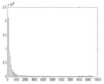
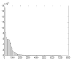
도 2a 및 도 2b는 밝은 이미지와 어두운 이미지 각각에 대한 픽셀들의 휘도에 따른 이미지의 픽셀들의 수를 도시한 예시적인 히스토그램들.
도 3은 하이라이트 프로젝터와 메인 프로젝터를 결합하는 예시적인 장치의 개략도.
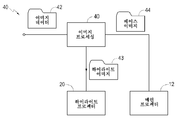
도 4는 예시적인 실시예에 따라 디스플레이 시스템의 이미지 데이터 처리 구성 요소들을 도시한 블록도.
도 5는 예시적인 실시예에 따라 광-재배향 프로젝터를 포함한 하이라이트 프로젝터를 도시한 개략도로서, 도 5에 도시된 형태의 하이라이트 프로젝터들은 예를 들어, 스크린, 메인 프로젝터의 구성 요소 또는 공간 광 변조기로 광을 투사하도록 구성될 수 있는, 하이라이트 프로젝터를 도시한 개략도.
도 6a는 덤프(dump)를 재배향하거나 또는 하이라이트 영역들의 외부의 이미지 영역들에서 광을 흡수하도록 제어되는, 공간 광 변조기로 원하는 하이라이트 이미지를 투사하도록 구성된 예시적인 홀로그램 프로젝터를 도시한 개략도.
도 6b는 예시적인 실시예에 따라 메인 프로젝터의 공간 광 변조기로 직접 하이라이트 이미지를 투사하도록 구성된 홀로그램 프로젝터를 도시한 개략도.
도 7은 예시적인 실시예에 따라 누출 광(leakage light)을 제거하기 위해 푸리에 평면의 공간 필터와 함께 2D 공간 광 변조기를 조명하도록 배열된 광원을 포함한 하이라이트 프로젝터를 도시한 개략도.
도 8은 예시적인 실시예에 따라 공간 광 변조기를 조명하는 광원을 포함한 하이라이트 프로젝터를 도시한 개략도.
도 9는 다른 실시예에 따른 디스플레이를 도시한 도면으로서, 도 9에 개략적으로 도시된 전체 아키텍처(architecture)를 가진 디스플레이들은 독립 디스플레이들로서 (예를 들어, 텔레비전, 컴퓨터 모니터, 특정한 목적의 디스플레이 등으로서) 또는 하이라이트 프로젝터를 포함하는 디스플레이 시스템의 부분으로서 사용될 수 있는, 디스플레이를 도시한 도면.1 is a schematic diagram of a display system according to an exemplary embodiment.
1A is a schematic diagram of a display system according to another exemplary embodiment.
2A and 2B are exemplary histograms showing the number of pixels of an image according to the luminance of pixels for each of a light image and a dark image.
3 is a schematic diagram of an exemplary device combining a highlight projector and a main projector.
Fig. 4 is a block diagram showing image data processing components of a display system according to an exemplary embodiment.
Fig. 5 is a schematic diagram showing a highlight projector including a light-reorienting projector according to an exemplary embodiment, wherein the highlight projectors of the type shown in Fig. 5 are, for example, screens, components of the main projector, or spatial light modulators. Schematic diagram showing a highlight projector, which can be configured to project light.
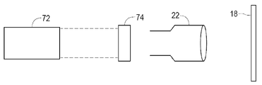
6A is a schematic diagram showing an exemplary hologram projector configured to project a desired highlight image with a spatial light modulator, which is controlled to redirect a dump or to absorb light in image regions outside of the highlight regions.
Fig. 6B is a schematic diagram showing a hologram projector configured to project a highlight image directly to the spatial light modulator of the main projector according to an exemplary embodiment.
Fig. 7 is a schematic diagram showing a highlight projector including a light source arranged to illuminate a 2D spatial light modulator with a Fourier plane spatial filter to remove leakage light according to an exemplary embodiment.
Fig. 8 is a schematic diagram showing a highlight projector including a light source illuminating a spatial light modulator according to an exemplary embodiment.
9 is a view showing a display according to another embodiment, and the displays having the overall architecture schematically shown in FIG. 9 are independent displays (eg, a television, a computer monitor, a specific purpose display, etc.) ) Or a diagram showing a display, which can be used as part of a display system comprising a highlight projector.
다음의 설명 동안 특정한 상세 사항들은 기술 분야의 숙련자들에게 더 완전한 이해를 제공하도록 제시된다. 그러나, 잘 공지된 요소들은 개시물을 불필요하게 애매하게 하는 것을 회피하도록 상세히 도시될 수 없거나 또는 설명될 수 없다. 따라서, 설명과 도면들은 제한하는 의미라기보다는, 예시적인 것으로서 간주되어야한다. Certain details during the following description are presented to provide a more complete understanding to those skilled in the art. However, well-known elements cannot be shown or described in detail to avoid unnecessarily obscuring the disclosure. Therefore, the description and drawings are to be regarded as illustrative rather than restrictive.
본 발명의 몇몇의 실시예들은 메인 프로젝터와 하이라이트 프로젝터를 포함한 투사형 디스플레이들을 제공한다. 메인 프로젝터는 낮은 피크 휘도를 가질 수 있고 전체 이미지를 투사하도록 사용될 수 있다. 메인 프로젝터에 의해 투사된 이미지에서 하이라이트들의 휘도는 원하는 것보다 더 낮다. 하이라이트 프로젝터는 하이라이트들의 위치(들)에서 휘도를 증가시키도록 집중된 광을 투사할 수 있어, 하이라이트들의 휘도를 상당히 증가시킨다. Some embodiments of the invention provide projection displays including a main projector and a highlight projector. The main projector can have a low peak luminance and can be used to project the entire image. The luminance of the highlights in the image projected by the main projector is lower than desired. The highlight projector can project focused light to increase the brightness at the location(s) of the highlights, thereby significantly increasing the brightness of the highlights.
도 1은 제 1 예시적인 실시예에 따른 투사 시스템(10)을 도시한다. 투사 시스템(10)은 스크린(18)으로 이미지(16)를 투사하는 렌즈(14)를 가진 메인 프로젝터(12)를 포함한다. 스크린(18)은 전면-투사 스크린 또는 후면-투사 스크린일 수 있다. 시스템(10)은 스크린(18)으로 이미지(16A)를 투사하는 렌즈(22)를 가진 각각의 하이라이트 프로젝터(20)를 또한 포함한다. 이미지들(16 및 16A)은 뷰어들이 이미지들(16 및 16A)의 조합으로부터 결과로 초래된 이미지를 보도록 겹쳐진다. 1 shows a
메인 프로젝터(12)는 임의의 적합한 이미지 프로젝터를 포함할 수 있다. 예를 들어, 메인 프로젝터(12)는 DLP-기반의 프로젝터, 하나 이상의 LCOS(liquid crystal on silicon) 공간 광 변조기들을 사용하는 프로젝터, 광을 변조하도록 투과형 액정 디스플레이(LCD) 패널을 포함한 프로젝터, CRT(cathode ray tube) 프로젝터 등을 포함할 수 있다. The
하이라이트 프로젝터(20)는 바람직하게 이미지(16) 내의 다른 영역들에서 광 레벨을 상당히 증가시키는 것 없이, 이미지(16)의 영역 내에서 적어도 몇몇의 영역들로 집중된 광을 전달할 수 있는 형태이다. 예를 들어, 하이라이트 프로젝터(20)는 이미지(16)의 선택된 하이라이트 영역들에만 추가의 휘도를 추가할 수 있도록 조사될 수 있는 하나 이상의 스캐닝 빔들을 포함할 수 있다. The
하이라이트 프로젝터(20)와 메인 프로젝터(12)는 동시에-등록되어(co-registered) 하이라이트 프로젝터(20)는 메인 프로젝터(12)에 의해 투사된 이미지(16) 내에서 작은 하이라이트 영역들로 추가의 광을 정확하게 전달할 수 있다. 몇몇의 실시예들에서, 하이라이트 프로젝터(20)는 메인 프로젝터(12)의 공간 해상도와 동일하거나 더 큰 공간 해상도를 갖는다. 다른 실시예들에서, 프로젝터(20)는 메인 프로젝터(12)보다 작은 공간 해상도를 가질 수 있다. 다른 실시예들에서, 프로젝터(20)는 메인 프로젝터(12)보다 작은 공간 해상도를 가질 수 있다. The
몇몇의 실시예들에서, 하이라이트 프로젝터(20)와 이미지 프로세서는 시중에 나온 디지털 시네마 프로젝터와 같은 기존의 메인 프로젝터로 애드-온(add-on)으로서 사용을 위해 제공된다. 이미지 프로세서는 투사를 위해 이미지 데이터를 수신하고 하이라이트 프로젝터에 의한 디스플레이를 위해 하이라이트 이미지를 생성하도록 구성될 수 있다. 몇몇의 실시예들에서, 이미지 프로세서는 기존의 메인 프로젝터에 의한 디스플레이를 위해 베이스 이미지를 제공하도록 이미지 데이터를 수정할 수 있다. 하이라이트 프로젝터는 기존의 메인 프로젝터에 의해 생성된 이미지들이 등록되는 하이라이트 이미지들을 생성하도록 설치 중에 캘리브레이트(calibrate)될 수 있다. In some embodiments, the
유리하게, 일반적인 의미들에서, 이미지의 픽셀들의 비교적 매우 적은 부분은 개선된 리얼리즘(realism)을 위해 표준 프로젝터(12)의 피크 휘도보다 더 큰 휘도를 갖으며 디스플레이될 필요가 있다. 개선된 리얼리즘은 밝은 하이라이트들을 매우 선택적으로 제공하여 성취될 수 있음이 밝혀졌다. 도 2a 및 도 2b는 높은 피크 휘도를 가진 디스플레이를 보기 위해 인간 컬러리스트(human colorist)에 의해 준비된 밝은 이미지와 어두운 이미지 각각에 대한 픽셀들의 휘도에 따른 이미지의 픽셀들의 수를 도시한 히스토그램들이다. 각각의 경우에서 컬러리스트가 최고의 모습이 되도록 고려되는 것을 위해 이미지를 조정했다. Advantageously, in general terms, a relatively very small portion of the pixels of the image need to be displayed with a brightness greater than the peak brightness of the
다소 놀랍게도, 밝은 이미지의 모든 픽셀들의 평균 밝기는 여전히 비교적 매우 낮다. 도 3a의 히스토그램을 가진 밝은 이미지에서도, 픽셀들의 비교적 매우 작은 부분만이 높은 휘도들(예를 들어, 약 1,000 또는 2,000 니트 이상의 휘도들)을 갖는다는 것이 보여질 수 있다. 높은 휘도와 매우 높은 휘도에서 몇몇의 매우 밝은 픽셀들은 뷰어들의 양안의 명순응에 상당히 영향을 미치지 않고 훨씬 더 현실 외관을 가진 이미지를 초래할 수 있다. 이는 많은 픽셀들 또는 모든 픽셀들이 매우 높은 휘도를 가질 수 있는 자연으로부터의 실제 풍경들과는 다르다. 예를 들어, 맑은 날 빙하의 실제 장면은 너무 밝을 수 있어서 어두운 선글라스 없이는 긴 기간들 동안 보는 것이 불편하거나 또는 심지어 해롭다. 컬러리스트는 보다 많은 현실 뷰잉 경험을 제공하도록 몇몇의 중요한 영역들에서 높은 휘도를 제공하는 동안 비교적 낮은 평균 휘도를 초래하는 방법으로 이러한 장면을 준비할 수 있다. Somewhat surprisingly, the average brightness of all pixels in a bright image is still relatively very low. Even in a bright image with the histogram of FIG. 3A, it can be seen that only a relatively small portion of pixels have high luminances (eg, luminances of about 1,000 or more than 2,000 nits). At high brightness and very high brightness, some very bright pixels can result in images with a much more realistic appearance without significantly affecting the brightness of both eyes of viewers. This is different from actual landscapes from nature where many pixels or all pixels can have very high luminance. For example, a real scene of a glacier on a clear day can be too bright, making it uncomfortable or even harmful to watch for long periods without dark sunglasses. The colorist can prepare such a scene in a way that results in a relatively low average luminance while providing high luminance in several important areas to provide a more realistic viewing experience.
몇몇의 실시예들은 작은 하이라이트 영역들이 이미지가 뷰어들에게 보여지는 평균 휘도보다 훨씬 높은 피크 휘도로 나타내진다면 실제의 뷰잉 느낌을 보존하는 동안 대단히 낮은 평균 휘도에서 심지어 매우 밝은 장면들이 제공될 수 있다는 사실을 이용한다. 몇몇의 실시예들은 가장 밝은 하이라이트들의 레벨에 대해 이미지(16)의 모든 픽셀들을 상승시키도록 전력 면에서 훨씬 매우 낮지만 원하는 레벨로 하이라이트들의 조도를 증가시킬 수 있는 하이라이트 프로젝터를 사용한다. 이러한 실시예들에서, 하이라이트 프로젝터로부터의 광은 하이라이트들에서 원하는 밝기를 제공하도록 하이라이트들로 집중된다. Some embodiments show that even small bright areas can be provided at very low average luminance while preserving the actual viewing feel if the small highlight areas are represented with a peak luminance much higher than the average luminance seen by viewers. To use. Some embodiments use a highlight projector that is much lower in power to increase all pixels of
메인 프로젝터와 하이라이트 프로젝터를 조합하여 배열하는 폭 넓게 다양한 방법들이 있다. 예를 들어, 하이라이트 영역들의 휘도를 선택적으로 증가시키기 위한 하이라이트 프로젝터와 메인 프로젝터를 제공하는 시스템들이 다음의 특징들의 임의의 조합을 갖도록 배열되어 제공될 수 있다:There are a wide variety of ways to arrange the main projector and highlight projector in combination. For example, systems that provide a highlight projector and a main projector for selectively increasing the brightness of highlight areas can be provided arranged to have any combination of the following features:
· 메인 프로젝터와 하이라이트 프로젝터는 동일한 전체 기술들 또는 다른 기술들을 사용할 수 있다.· The main projector and the highlight projector can use the same overall technologies or different technologies.
· 메인 프로젝터와 하이라이트 프로젝터는 각각의 유닛들의 형태로 또는 조합된 유닛(예를 들어, 통합된 형태의 인자)의 형태로 제공될 수 있다. 메인 프로젝터와 하이라이트 프로젝터가 조합된 유닛의 형태로 제공된다면 메인 프로젝터와 하이라이트 프로젝터는 특정한 광학 구성 요소들 및/또는 특정한 광학 경로들을 공유할 수 있다. 예를 들어, 메인 프로젝터와 하이라이트 프로젝터는 하나 이상의 투사 렌즈, 릴레이 렌즈들(relay optics), 하나 이상의 공간 광 변조기들 등을 공유할 수 있다. 공유된 구성 요소들과 광학 경로들의 다양한 예들이 아래에 제시되어 있다.The main projector and the highlight projector can be provided in the form of individual units or in the form of a combined unit (eg an integrated form factor). If the main projector and the highlight projector are provided in the form of a combined unit, the main projector and the highlight projector can share specific optical components and/or specific optical paths. For example, a main projector and a highlight projector can share one or more projection lenses, relay optics, one or more spatial light modulators, and the like. Various examples of shared components and optical paths are presented below.
· 시스템은 베이스 이미지를 총체적으로 투사하는 하나 이상의 메인 프로젝터들을 포함할 수 있다. 예를 들어, 시스템(10)은 이미지(16)를 제공하도록 총체적으로 스크린(18)을 조명하는 복수의 메인 프로젝터들(12)을 포함할 수 있다. The system can include one or more main projectors that collectively project the base image. For example,
· 시스템은 하이라이트 영역들의 조도를 증가시키도록 하이라이트 이미지를 총체적으로 투사할 수 있는 하나 이상의 하이라이트 프로젝터들을 포함할 수 있다. 예를 들어, 하이라이트 프로젝터(20)는 이미지(16)의 하이라이트 영역들로 총체적으로 광을 조사하도록 제어될 수 있는 복수의 유닛들을 포함할 수 있다. The system may include one or more highlight projectors that can project the highlight image collectively to increase the illuminance of the highlight areas. For example, the
· 하이라이트 프로젝터는 단색(예를 들어, 백색광을 투사할 수 있음) 또는 다색일 수 있다.· Highlight projectors can be monochromatic (eg, capable of projecting white light) or multicolored.
· 하이라이트 프로젝터는 하이라이트 영역들 외부의 조도를 억제하도록 여과(예를 들어 푸리에 평면에서 공간 필터와 같은)를 선택적으로 포함할 수 있다. The highlight projector can optionally include filtration (eg, spatial filters in the Fourier plane) to suppress the illuminance outside the highlight areas.
· 하이라이트 프로젝터는 하나 이상의 공간 광 변조기들을 선택적으로 포함할 수 있다. 공간 광 변조기(들)은 다음의 단계들 중 하나 이상을 실행하도록 제어될 수 있다: 투사된 하이라이트 이미지에서의 에러들을 정정하는, 하이라이트 영역들을 조명하도록 광을 조사하는 단계, 하이라이트 영역들 외부의 조도를 억제하는 단계, 메인 프로젝터에 의해 투사된 베이스 이미지 내로 부드럽게 섞이도록 하이라이트 이미지를 조정하는 단계 및 하이라이트 영역들의 외부로부터 하이라이트 영역들로 광을 재배향하는 단계. 하이라이트 프로젝터가 하나 이상의 공간 광 변조기들을 포함하는 실시예들에서, 메인 프로젝터에 의해 공유된 공간 광 변조기(들)를 포함할 수 있고 및/또는 하이라이트 프로젝터에 대해 전용인 공간 광 변조기(들)를 포함할 수 있다.The highlight projector can optionally include one or more spatial light modulators. The spatial light modulator(s) can be controlled to perform one or more of the following steps: correcting errors in the projected highlight image, irradiating light to illuminate the highlight areas, illuminance outside the highlight areas Restraining, adjusting the highlight image to blend smoothly into the base image projected by the main projector, and redirecting light from outside of the highlight areas to the highlight areas. In embodiments where the highlight projector includes one or more spatial light modulators, it may include spatial light modulator(s) shared by the main projector and/or include spatial light modulator(s) dedicated to the highlight projector. can do.
메인 프로젝터와 하이라이트 프로젝터는 전면-투사 또는 후면-투사를 위해 배열될 수 있다. 하이라이트 프로젝터(20)와 메인 프로젝터(12)가 동일한 측면으로부터 스크린(18)을 조명하는 것이 의무적이진 않다. 실시예들에서 스크린(18)이 반투명한 경우에(예를 들어, 스크린(18)은 스크린의 후면-투사 형태를 포함함), 하이라이트 프로젝터(20)와 메인 프로젝터(12)는 반대 편의 측면들로부터 스크린(18)을 조명할 수 있다.The main projector and the highlight projector can be arranged for front-projection or rear-projection. It is not mandatory for the
이 다양한 방법들과 그 변경들 및 조합들은 제한적이지 않지만 본 발명의 범위 내에서 몇몇의 실시예들의 예들을 제공하도록 의도된다. These various methods and their variations and combinations are not limited, but are intended to provide examples of some embodiments within the scope of the present invention.
유리하게, 뷰어에 의해 보여진 바와 같이, 결합된 이미지는 피크 휘도가 메인 프로젝터(12)의 피크 휘도를 상당히 초과하는 몇몇의 하이라이트들을 포함한다. 예를 들어, 메인 프로젝터는 하이라이트 영역들이 2000 니트 이상의 피크 휘도를 가질 수 있는 동안 500 니트의 피크 휘도를 가질 수 있다. 어두운 시야 환경들(예를 들어, 영화관들)에서의 사용을 위해 의도된 몇몇의 메인 프로젝터들은 예를 들어 15 내지 50 니트의 피크 휘도를 제공할 수 있다. 이러한 몇몇의 프로젝터들은 넓은-영역의 스크린들로 이미징하도록 설계된다. 밝은 시야 환경들에서의 사용을 위해 의도된 몇몇의 메인 프로젝터들은 예를 들어, 100 내지 300 니트의 피크 휘도를 제공할 수 있다. Advantageously, as seen by the viewer, the combined image includes some highlights whose peak luminance significantly exceeds the peak luminance of the
하이라이트 프로젝터(20)에 의해 조명된 하이라이트 영역들이 이미지(16)의 영역의 매우 작은 부분(예를 들어, 10%, 5%, 1% 미만 또는 심지어 0.1% 미만)만을 포함할 수 있기 때문에, 하이라이트 프로젝터(20)는 비현실적인 전력 입력을 요구하는 일 없이 하이라이트 영역들에서 원하는 높은 휘도를 성취할 수 있다. Highlights Because highlight areas illuminated by
도 1a는 하이라이트 프로젝터가 스캐닝 거울들(23A 및 23B)을 포함하는 디플렉터(deflector; 23) 및 광의 좁은 빔(21)을 생성하는 스폿 광원(20A)을 포함하는 예시적인 실시예에 따른 프로젝터 시스템을 도시한다. 거울들(23A 및 23B)은 광 빔(21)이 이미지(16)의 임의의 원하는 위치에서 작은 스폿(25)을 형성하도록 안내될 수 있도록 액추에이터들(actuator)(도시되지 않음)에 의해 작동되고 선회하여 장착된다. 광 빔(21)의 강도와 스폿(25)이 디스플레이되는 위치들은 선택된 하이라이트 영역들에서 증가된 휘도를 성취하도록 제어기(24)에 의해 제어될 수 있다. 몇몇의 실시예들에서, 하이라이트 영역의 밝기는 스폿(25)이 하이라이트 영역에 있도록 제어되는 시간의 양을 변화시킴으로써 적어도 부분적으로 제어된다. 몇몇의 실시예들에서, 하이라이트 영역의 밝기는 빔(21)이 하이라이트 영역을 조명하는 동안 빔(21)의 듀티 사이클(duty cycle) 및/또는 강도를 제어하여 적어도 부분적으로 제어된다. 1A shows a projector system according to an exemplary embodiment in which the highlight projector comprises a
빔(21)은 예를 들어, 레이저 빔을 포함할 수 있다. 몇몇의 실시예들에서 하이라이트 프로젝터는 백색의 하이라이트들을 만들도록 결합될 수 있는 다른 색들의 3개의 레이저 빔들을 포함한다. 예를 들어 하이라이트 프로젝터는 빨간색, 초록색 그리고 파란색 레이저 빔들을 포함할 수 있다. 이러한 실시예들에서 빔들은 단일 디플렉터 어셈블리(예를 들어, 거울들(23A, 23B)의 단일 세트)에 의해 하이라이트 영역들을 조명하도록 조종될 수 있다. 대안적인 실시예들에서 각각의 편향 어셈블리는 복수의 빔들(21) 각각에 제공된다. The
하이라이트들만이 이미지(16)의 전체 영역의 작은 부분에 일반적으로 나타나기 때문에, 레이저는 이러한 영역들에서 보다 길게 있음으로써 하이라이트 영역들의 인지된 밝기를 증가시킬 수 있다. 레이저는 하이라이트 영역들의 외부에서 이미지(16)의 임의의 부분들을 조명할 필요가 없다. Since only the highlights generally appear in a small portion of the entire area of the
하이라이트 프로젝터가 조종 가능한 광 빔을 포함하는 실시예들에서, 광 빔을 조종하는 제어기(예를 들어, 제어기(24))는 스폿(25)이 조명될 하이라이트 영역들의 위치들에 의존하는 궤도를 따르도록 거울들(23A 및 23B)(또는 디지털 광 디플렉터들, 회절 광 밸브들 등을 사용하는 메커니즘과 같은 대안적인 빔-조종 메커니즘)을 제어하도록 구성될 수 있다. 빔 조종 메커니즘이 이미지(16)의 모든 픽셀들을 다루는 다른 패턴 또는 레스터(raster)로 스캔될 필요는 없다. 하이라이트 영역들의 외부에 있는 적어도 몇몇의 픽셀들을 회피하는 동안 하이라이트 영역들에 대해 스폿(25)을 취하는 궤도의 스폿(25)을 조종함으로써, 제어기(25)는 스폿(25)이 하이라이트 영역들의 원하는 휘도를 성취하는 데 충분한 기간 동안 하이라이트 영역들에 있도록 할 수 있다. In embodiments where the highlight projector includes a steerable light beam, a controller that steers the light beam (e.g., controller 24) follows a trajectory that depends on the locations of the highlight areas where the
메인 프로젝터(12)와 하이라이트 프로젝터(20)는 2개의 프로젝터들이 몇몇의 공통의 광학 경로들을 공유하도록 선택적으로 서로 통합될 수 있다. 예를 들어, 하이라이트 프로젝터(20)와 메인 프로젝터(12)의 광학 시스템들은 공통의 투사 렌즈(14)를 공유하도록 배열될 수 있다. 이것의 하나의 예는 도 3에 도시되어 있다. 도 3은 사실상 개략적이다. 릴레이 렌즈들, 거울들, 필터들 등과 같은 광학 경로들에 나타날 수 있는 광학 구성 요소들은 명료성을 위해 생략되었다. The
도 3에 도시된 실시예에서, 메인 프로젝터(12)는 공간 광 변조기(32)를 조명하도록 광(31)을 방출할 수 있는 광원(30)을 포함한다. 광원(30)은 균일한 광원 또는 이미지 데이터(예를 들어 베이스 이미지)에 따라 공간적으로 변조될 수 있는 광원을 포함할 수 있다. 공간 광 변조기(32)에 의해 변조된 광은 이미지(16)(도 3에 도시되지 않음)를 제공하도록 스크린(18)(도 3에 도시되지 않음)으로 투사 렌즈(14)에 의해 조사된다. In the embodiment shown in Figure 3, the
이 실시예에서, 하이라이트 프로젝터는 공간 광 변조기(32) 상의 밝게 조명된 스폿(38)을 생성하도록 X-Y 디플렉터(36)와 광학 결합기(37)에 의해 조종되는 광(35)의 좁은 빔을 방출하도록 제어될 수 있는 높은-강도의 좁은 빔 광원(34)을 포함한다. 강도를 제어하여 및/또는 X-Y 스캐너(36)로 스캐닝하는 동안 광원(34)을 턴 온 또는 턴 오프하여, 복수의 다른 하이라이트 영역들은 광원(34)으로부터 광으로 공간 광 변조기(32)에 조명될 수 있다. 공간 광 변조기(32)에 의해 변조된 바와 같이, 이 추가의 광은 이미지(16) 내에서 하이라이트 영역들의 휘도를 더하도록 렌즈(14)에 의해 또한 이미징된다. In this embodiment, the highlight projector is configured to emit a narrow beam of light 35 steered by the
대안적인 실시예에서, 광학 결합기(37)는 스폿(38)이 스크린(18)으로 직접 투사되도록 공간 광학 변조기(32)와 투사 렌즈(14) 사이에 위치된다. 대안적인 실시예에서 메인 프로젝터와 하이라이트 프로젝터의 광학 경로들은 공통으로 투사 렌즈(14)만을 가질 수 있다. In an alternative embodiment, the
도 4는 예시적인 실시예에 따라 디스플레이 시스템의 이미지 데이터 처리 구성 요소들을 도시한 블록도이다. 이미지 처리 시스템(40)은 이미지 데이터(42)를 수신하고 하이라이트 영역들을 식별하도록 이미지 데이터(42)를 처리한다. 프로세싱은 예를 들어, 픽셀 휘도 값들과 제 1 임계치를 비교하는 것 및 하이라이트 영역들에 속하는 것으로서 제 1 임계치를 초과하는 휘도 값들을 가진 이러한 픽셀들을 식별하는 것을 포함할 수 있다. 몇몇의 실시예들에서 하이라이트 영역들은 제 1 임계치를 초과하는 휘도 값들을 가진 연결된 픽셀들의 사전결정된 영역을 포함하는 영역들에 제한될 수 있다. 또 다른 예로서, 프로세싱은 M개의 가장 높은 휘도 픽셀들(여기서 M은 수) 또는 휘도에 대한 N번째 백분위수(percentile)에 있거나 또는 N번째 백분위수 위에 있는 이러한 픽셀들(여기서 N은 90th 백분위수 또는 95th 백분위수 또는 98th 백분위수 또는 99th 백분위수 또는 99.9th 백분위수와 같은 백분위 수임)로 구성되는 것으로서 하이라이트 영역들을 식별할 수 있다. 프로세싱은 복수의 이러한 기준(예를 들어, 하이라이트 영역들은 휘도가 임계치를 초과하는 최대 M개의 픽셀들로서 식별될 수 있음)을 적용하는 것을 포함할 수 있다. Fig. 4 is a block diagram showing image data processing components of a display system according to an exemplary embodiment. The
몇몇의 실시예들에서, 프로세싱은 하이라이트 영역들에 포함된 영역에 대해 피크 휘도를 트레이딩 오프(trading off)하는 것을 포함한다. 이러한 프로세싱은 히스토그램 분석을 포함할 수 있다. 예를 들어, 프로세싱이 제 1 기준에 따른 하이라이트 영역들에 속하는 것으로서 비교적 많은 수의 픽셀들을 식별하는 이미지에 대해, 프로세싱은 하이라이트 영역들에서 성취 가능한 감소된 피크 휘도를 감안하고 제 1 기준에 따른 하이라이트 영역들을 유지하는 것 또는 하이라이트 영역들에 포함된 픽셀들의 수를 감소시키도록 제 2 기준을 적용하는 것 사이에서 선택될 수 있다. 이러한 프로세싱은 히스토그램 분석을 포함할 수 있다.In some embodiments, processing includes trading off peak luminance for an area included in the highlight areas. Such processing may include histogram analysis. For example, for an image where processing identifies a relatively large number of pixels as belonging to highlight areas according to the first criterion, processing takes into account the reduced peak luminance achievable in the highlight areas and highlights according to the first criterion It may be selected between maintaining the areas or applying a second criterion to reduce the number of pixels included in the highlight areas. Such processing may include histogram analysis.
몇몇의 실시예들에서, 프로세싱이 어댑테이션 포인트(adaptation point)를 참고로 하여 실행된다. 어댑테이션 포인트는 예를 들어, 이미지의 대수 평균 휘도를 포함할 수 있거나 또는 이미지의 대수 평균 휘도로부터 결정될 수 있다. 비디오 이미지들의 경우에 어댑테이션-포인트는 몇몇의 이전의 이미지들에 걸쳐 시간 평균(temporal average)을 포함할 수 있다. 이러한 실시예들에서, 하이라이트 영역들을 식별하는 프로세싱은 적어도 하나의 임계치 양에 의한 어댑테이션 포인트보다 큰 휘도를 가진 픽셀들을 식별하는 것을 포함할 수 있다. In some embodiments, processing is performed with reference to an adaptation point. The adaptation point may include, for example, the logarithmic average luminance of the image or may be determined from the logarithmic average luminance of the image. In the case of video images, the adaptation-point may include a temporal average over several previous images. In these embodiments, processing identifying highlight areas may include identifying pixels having a luminance greater than an adaptation point by at least one threshold amount.
이미지 프로세싱 시스템(40)은 하이라이트 프로젝터(20)로 전달되는 하이라이트 이미지(43)를 생성한다. 하이라이트 이미지(43)는 하이라이트 영역들에서 증가된 밝기를 제공하도록 하이라이트 프로젝터(20)에 의해 디스플레이된다. 하이라이트 영역들의 외부의 픽셀들은 하이라이트 이미지(43)에서 매우 작은 값 또는 0의 값을 가질 수 있다. 이미지 프로세싱 시스템(40)은 메인 프로젝터(12)에 의한 투사를 위해 베이스 이미지(44)를 또한 전달한다.The
몇몇의 실시예들에서, 베이스 이미지(44)는 이미지 데이터(42)와 동일하다. 다른 실시예들에서, 베이스 이미지(44)는 메인 프로젝터(12)에 의해 먼저 또는 완전히 조명되는 이미지(16)의 베이스 영역들과 하이라이트 프로젝터(20)에 의해 먼저 조명되는 하이라이트된 영역들 사이의 부드러운 이동(transition)을 제공하도록 처리된다. 이 프로세싱은 예를 들어, 베이스 이미지(44)를 제공하도록 이미지 데이터(42)로부터 하이라이트 구성 요소들을 추출하는 것을 포함할 수 있다. 몇몇의 실시예들에서 프로세싱은 하이라이트 이미지(43)를 디스플레이하도록 구동될 때 하이라이트 프로젝터(20)에 의해 이미지 픽셀들로 전달될 것인 휘도를 추정하는 것과 베이스 이미지(44)를 생성하는 데에 있어서 그 추정된 휘도를 보상하는 것을 포함한다. 몇몇의 실시예들에서 추정은 하이라이트 프로젝터(20)의 광학 시스템의 특성들을 모델링할(model) 수 있다. 몇몇의 실시예들에서 추정은 하이라이트 영역들의 외부의 픽셀들에 대해 하이라이트 프로젝터(20)에 의해 전달된 광을 추정할 수 있다. 메인 프로젝터(12)와 하이라이트 프로젝터(20)의 색과 휘도는 이러한 부드러운 이동들을 용이하게 하도록 캘리브레이트될 수 있다. In some embodiments, base image 44 is the same as
하이라이트 이미지(43)는 다양한 형태들을 취할 수 있다. 몇몇의 실시예들에서, 하이라이트 이미지(43)는 바이너리 이미지("ON" 상태의 모든 픽셀들은 동일한 레벨로 설정됨)를 포함할 수 있고 바이너리 이미지로서 처리될 수 있다. 이러한 실시예들은 예를 들어, 어댑테이션 포인트 위의 휘도들을 가진 픽셀들로 구성됨으로써 하이라이트 영역들을 선택하는 하이라이트 영역들을 선택하기 위한 프로세스와 결합하여 사용될 수 있다. 이러한 실시예들은 인간 시각 시스템이 어댑테이션 포인트 위에 있는 광과 유사하게 응답하는 사실을 이용할 수 있다. 예를 들어, 뷰어는 하이라이트 픽셀들이 두 이미지들에서 어댑테이션 포인트 위의 휘도들을 갖는 한, 특정한 하이라이트 픽셀들이 10000 니트의 휘도를 갖는 이미지와 동일한 하이라이트 픽셀들이 15000 니트의 휘도를 갖는 다른 이미지 사이에서의 많은 차이 또는 어떤 차이를 말할 수 없을 수 있다. 몇몇의 이러한 실시예들은 하이라이트 픽셀들 위에서 동일하게 하이라이트 프로젝터로부터의 휘도를 분포시킴으로써 및/또는 설정된 레벨로 하이라이트 픽셀들의 휘도를 클립핑(clipping)함으로써 작동할 수 있다. The
다른 실시예들에서 하이라이트 프로젝터는 다른 하이라이트 픽셀들 또는 영역들에 다른 휘도들을 공급하도록 제어될 수 있다. 또 다른 실시예들에서 하이라이트 프로젝터는 방법들의 결합에 따라 제어될 수 있다. 예를 들어, 하이라이트 프로세서는 이미지 데이터가 제 1 범위에서 휘도를 명시하는 하이라이트 픽셀들에 다른 휘도들을 공급하고 이미지 데이터가 제 1 범위의 상부 위의 휘도를 명시하는 하이라이트 픽셀들에 동일한 휘도를 공급하도록 제어될 수 있다. 제 1 범위는 고정되거나 또는 변할 수 있다. 예를 들어, 가변적인 제 1 범위는 현재의 어댑테이션 포인트, 하이라이트 영역들에 있음으로써 식별된 복수의 픽셀들, 하이라이트 영역들에 있음으로써 식별된 픽셀들의 통계 자료(예를 들어, 하이라이트 픽셀들의 최대값, 평균, 평균 등), 그것들의 조합들 등에 기초할 수 있다. In other embodiments, the highlight projector can be controlled to supply different luminances to different highlight pixels or regions. In still other embodiments, the highlight projector can be controlled according to a combination of methods. For example, the highlight processor allows image data to supply different luminances to highlight pixels specifying luminance in the first range and image data to supply the same luminance to highlight pixels specifying luminance above the top of the first range. Can be controlled. The first range can be fixed or variable. For example, the variable first range is the current adaptation point, a plurality of pixels identified by being in highlight areas, and statistical data of pixels identified by being in highlight areas (eg, the maximum value of highlight pixels) , Average, average, etc.), combinations thereof, and the like.
이미지 데이터 프로세싱은 다양한 방법들로 분포될 수 있다. 예를 들어, 몇몇의 실시예들에서, 이미지 프로세싱 시스템(40)은 이미지 데이터(42)가 하이라이트 이미지(43)를 내부로 끌어내는 하이라이트 프로젝터에 직접 제공되도록 하이라이트 프로젝터와 통합된다. 몇몇의 대안적인 실시예들에서, 프로세싱은 하이라이트 이미지 데이터(43)가 베이스 이미지 데이터(44)와 함께 공급되도록 업스트림(upstream)에서 실행된다. 예를 들어, 하이라이트 이미지 데이터(43)는 스트림에서 베이스 이미지 데이터(44), 파일 또는 다른 데이터 구조와 함께 인코딩(encoded)될 수 있다. 이러한 실시예들에서, 프로젝터 시스템은 하이라이트 이미지 데이터(43)를 추출하고 메인 프로젝터가 베이스 이미지 데이터(44)에 따라 이미지들을 디스플레이하도록 하는 동안 베이스 이미지 데이터(43)를 사용하여 하이라이트 프로젝터를 제어하도록 구성될 수 있다. Image data processing can be distributed in a variety of ways. For example, in some embodiments,
하이라이트 프로젝터는 많은 다른 형태들을 취할 수 있다. 하이라이트 프로젝터를 위해 사용될 수 있는 다른 기술들의 몇몇의 예들은 다음의 것들을 포함한다: 스캐닝 스폿 프로젝터들(이러한 프로젝터들의 몇몇의 예시적인 실시예들은 상술되어 있음); 홀로그램 프로젝터들(예를 들어, 광학 시스템의 푸리에 평면에서 광을 위상 변조하여 이미지 표면에 이미지들을 형성하도록 광을 집중시키는 프로젝터들).Highlight projectors can take many different forms. Some examples of other techniques that can be used for a highlight projector include: scanning spot projectors (some exemplary embodiments of these projectors are described above); Hologram projectors (eg, projectors that phase modulate light in the Fourier plane of an optical system to focus light to form images on the image surface).
스캐닝 프로젝터의 대안적인 형태는 스크린(18)으로 공간적으로-변조된 광의 스트립(stripe)을 생성하는 1D 광 변조기와 스크린(18)을 가로질러 스트립을 스캔하는 스캐너를 포함한다. 비-제한적인 예로서, 1D 변조기는 편광 빔 스플리터(splitter)와 스캐닝 거울과 결합하여 1D 편광 변조기를 포함할 수 있다. Alternative forms of scanning projectors include a 1D light modulator that creates a strip of spatially-modulated light onto the
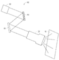
또 다른 예시적인 실시예는 도 5에 도시되어 있다. 도 5는 광-재배향 프로젝터를 포함한 하이라이트 프로젝터(50)를 개략적으로 도시한다. 이러한 프로젝터들의 하나의 일반적인 형태는 회절-기반/위상 변조 방법을 적용함으로써 다른 영역들을 제외하고 몇몇의 영역들에 광을 집중시키는 프로젝터들을 포함한다. 이 방법은 때때로 "홀로그램 2D 투사"로서 지칭된다.Another exemplary embodiment is shown in FIG. 5. 5 schematically shows a
도 5에 도시된 실시예에서, 하이라이트 프로젝터는 코히어런트 광원(51)(도시된 실시예에서, 광원(51)은 레이저(51A)와 빔 익스팬더(beam expander; 51B)를 포함함), 프로젝터의 광학 경로에서 광학 푸리에 평면에 위치된 위상 변조 패널(52) 및 원하는 하이라이트 이미지의 역 푸리에 변환의 실수 성분에 따라 위상 변조기(52)의 위상-시프팅 효과(phase-shifting effect)를 공간적으로 변경하는 제어기(54)를 포함한다. 제어기(54)는 하이라이트 이미지에 대응하는 푸리에-기반 홀로그램(때때로 컴퓨터로-생성된 홀로그램으로 지칭됨)을 결정하고 컴퓨터로 생성된 홀로그램에 따라 위상 변조 패널(52)의 다른 위치들에서 위상을 설정하도록 구성될 수 있다. 광원(51)으로부터의 광과 제어기(54)에 의해 생성된 푸리에-기반 홀로그램에 따라 제어된 위상 변조 패널(52)의 상호 작용은 하이라이트 이미지의 레크리에이션(recreation)을 초래한다. 렌즈(22)는 스크린(18)으로 결과로 초래된 이미지를 투사한다(도 5에 도시되지 않음). In the embodiment shown in Fig. 5, the highlight projector is a coherent light source 51 (in the illustrated embodiment, the
몇몇의 실시예들에서 하이라이트 프로젝터는 가변적인-강도의 광원들을 가진 하나 이상의 홀로그램 프로젝터들을 포함한다. 광원(들)의 강도는 하이라이트 이미지의 디스플레이 위의 추가의 제어를 제공하도록 제어될 수 있다. In some embodiments the highlight projector includes one or more hologram projectors with variable-intensity light sources. The intensity of the light source(s) can be controlled to provide additional control over the display of the highlight image.
몇몇의 실시예들에서, 하이라이트 프로젝터는 다른 색의 광을 각각 투사하는 복수의 홀로그램 프로젝터들을 포함한다. 예를 들어, 하나의 홀로그램 프로젝터는 빨간색의 광원(51)을 포함할 수 있고 하이라이트 이미지의 빨간색 채널을 디스플레이하도록 제어될 수 있다. 이러한 프로젝터는 초록색 광원과 파란색 광원을 포함하고 하이라이트 이미지의 초록색 채널과 파란색 채널을 이미징하도록 각각 제어되는 홀로그램 프로젝터들과 결합하여 사용될 수 있다. In some embodiments, the highlight projector includes a plurality of hologram projectors that each project light of different colors. For example, one hologram projector can include a
위상 변조기를 변경하여 이미지들을 생성하는 형태의 현재의 프로젝터들은 위상 변조기의 한정된 해상도 때문에 및/또는 원하는 이미지의 역 푸리에 변환이 일반적으로 실제 부분 및 가상 부분 둘 다를 가질 것이고 전형적인 위상 변조기만이 역 푸리에 변환의 하나의 부분을 구현하기 때문에 광의 상당한 누출이 있을 수 있는 손실을 갖는다. 이러한 광 누출은 위상 변조된 광이 공간 광 변조기(DMD 어레이, LCOS 변조기, LCD 패널 등과 같은)를 조명하도록 이미징되는 실시예들에서 하이라이트 프로젝터들에서 부분적으로 또는 실질적으로 완전히 보상될 수 있다. 이러한 실시예들에서, 공간 변조기는 하이라이트 영역들 외부에서 광의 양을 감소시킴으로써 투사된 하이라이트 이미지를 치우도록 작동될 수 있다. 이 목적을 위해 사용된 공간 변조기는 메인 프로젝터에서 사용된 공간 변조기와는 상이할 수 있거나 또는 동일할 수 있다. Current projectors in the form of altering the phase modulator to generate images, because of the limited resolution of the phase modulator and/or the inverse Fourier transform of the desired image will generally have both real and virtual parts, and only a typical phase modulator inverse Fourier transform Since it implements one part of the light, there is a loss that can be a significant leakage of light. Such light leakage can be partially or substantially completely compensated in highlight projectors in embodiments where the phase modulated light is imaged to illuminate a spatial light modulator (such as a DMD array, LCOS modulator, LCD panel, etc.). In these embodiments, the spatial modulator can be operated to remove the projected highlight image by reducing the amount of light outside the highlight areas. The spatial modulator used for this purpose may be different or the same as the spatial modulator used in the main projector.
광 누출은 높은 공간 해상도를 가진 위상 변조기 패널(52)을 제공함으로써 감소될 수 있다. 몇몇의 실시예들에서, 위상 변조기 패널(52)은 하이라이트 이미지의 공간 해상도를 초과한 공간 해상도를 갖는다. 몇몇의 실시예들에서, 위상 변조기 패널(52)의 제어가능한 요소들의 수는 하이라이트 이미지의 픽셀들의 수의 9배 이거나 또는 더 많다. Light leakage can be reduced by providing a
홀로그램 프로젝터는 비-평면 촛점면으로 하이라이트 이미지를 투사하도록 선택적으로 구성될 수 있다. 제어기(54)는 원하는 비-평면 표면으로 초점을 맞추는 위상 변조기에 대해 구동 신호들을 생성하도록 구성될 수 있다. 예를 들어, 홀로그래프(holograph)는 곡면 스크린 또는 공간 광 변조기에 포커싱된(focused) 이미지를 생성하도록 구성될 수 있다.The hologram projector can be selectively configured to project a highlight image onto a non-planar focal plane. The
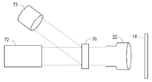
도 6a에 도시된 실시예에서, 홀로그램 프로젝터(72)는 하이라이트 영역들의 외부에서 이미지 영역들의 광을 재배향하거나 또는 덤프하거나 또는 흡수하도록 제어되는 공간 광 변조기(74)로 원하는 하이라이트 이미지를 투사한다. 따라서 공간 광 변조기(74)로부터의 광은 예를 들어 투사 렌즈(22)에 의해 스크린(18)으로 이미징된다. 공간 광 변조기는 예를 들어, 홀로그램 프로젝터(72)에 의해 생성된 광의 실제의 분포의 추정을 얻도록 홀로그램 프로젝터(72)의 작동의 시뮬레이션을 실행하여 제어될 수 있다. 따라서 이 추정은 하이라이트 이미지와 비교될 수 있다. 비교는 예를 들어, 추정과 하이라이트 이미지의 비율 또는 차이를 결정하는 것을 포함할 수 있다. 공간 광 변조기(74)는 홀로그램 프로젝터(72)에 의해 실제로 투사된 광 패턴과 원하는 하이라이트 이미지 사이의 차이들을 보상하도록 비교의 결과에 따라 제어될 수 있다. 추정을 계산하는 것은 예를 들어 프로그램된 데이터 프로세서, 하드-구성된 논리 회로들 및/또는 구성 가능한 논리 회로들(예를 들어, 필드-프로그램 가능 게이트 어레이들(FPGA들))을 사용하여 실행될 수 있다. 계산은 홀로그램 프로젝터(72)의 위상 변조기에 의해 생성된 위상-시프트된 광 필드를 추정하는 것과 추정된 광 필드의 푸리에 변환을 계산하는 것을 포함할 수 있다. In the embodiment shown in FIG. 6A, the
몇몇의 실시예들에서, 하이라이트 영역들 외부로의 광의 발산(spreading)은 푸리에 평면에서 DC 성분을 차단하여 감소된다. 도 6b에 도시된 예시적인 실시예에서, 홀로그램 프로젝터(72)는 메인 프로젝터의 공간 광 변조기(76)로 직접 하이라이트 이미지를 투사한다. 공간 광 변조기(76)는 또한 광원(73)에 의해 조명된다. In some embodiments, the spreading of light outside the highlight areas is reduced by blocking the DC component in the Fourier plane. In the exemplary embodiment shown in FIG. 6B, the
도 7은 대안적인 아키텍처(architecture)를 가진 프로젝터(60)를 개략적으로 도시한다. 프로젝터(60)는 광원(62)(코히어런트 광원일 필요는 없음)을 포함한다. 광원(62)은 아날로그 DMD 거울 어레이와 같은 2D 공간 광 변조기(64)를 조명한다. 공간 광 변조기(64)는 스크린(18) 상의 다른 위치들로 광을 안내할 수 있는 제어 가능한 요소들을 갖는다. 몇몇의 실시예들에서, 공간 광 변조기(64)는 하이라이트 이미지를 제공하도록 투사 렌즈(66)에 의해 스크린(18)으로 직접 이미징된다. 몇몇의 실시예들에서, 공간 광 변조기(64)는 다른 공간 광 변조기(65)를 조명한다. 공간 광 변조기(65)는 예를 들어, 메인 프로젝터에 의해 또한 사용되는 공간 광 변조기를 포함할 수 있다(도 7에 도시되지 않음).7 schematically shows a
다른 대안적인 실시예에 따른 하이라이트 프로젝터(80)가 도 8에 도시되어 있다. 하이라이트 프로젝터(80)는 공간 광 변조기(83)를 조명하는 광원(82)을 포함한다. 예시적인 적용에서, 공간 광 변조기(83)는 하이라이트 영역들 외부의 모든 픽셀들이 스크린(18)으로 광을 통과 못 하도록 설정되기 위해 제어된다. 공간 광 변조기(83)가 완벽하지 않기 때문에, 몇몇의 광은 하이라이트 영역들 외부의 픽셀들에 의해 지나간다. 이 누출 광은 블랙 레벨(예를 들어, 블랙들은 전체 이미지에 걸쳐 회색 외관을 취함)의 증가로서 뷰어들에 의해 인지될 수 있다. 하이라이트 프로젝터(80)는 도시된 실시예에서 공간 광 변조기(83)와 스크린(18) 사이의 광학 경로의 푸리에 평면에 제공된 마스크(85)를 포함하는 공간 필터(84)를 포함한다. 마스크(85)는 DC 공간 주파수 성분(즉, 디스플레이된 이미지의 모든 픽셀들에 영향을 미치는 신호의 성분)을 차단하여 여전히 하이라이트들을 지나가는 동안 블랙 레벨을 증가시킨다.A
메인 프로젝터 또는 홀로그램 프로젝터를 위한 광원이 코히어런트 광의 소스를 포함하는 시스템들은 투사된 이미지들에서 레이저 스펙클(speckle)의 출현을 감소시키도록 구성된 하나 이상의 광학 구성 요소들을 포함할 수 있다. 임의의 적합한 스펙클-감소 기술이 적용될 수 있다. 예를 들어, 레이저 스펙클을 감소시키기 위한 다양한 기술들이 기술 분야에 공지되어 있다. 기술들은: 광학 경로에서 진동 확산기를 제공하는 것; 코히어런트 광원의 위상을 랜덤화(randomizing)하는 것, 코히어런트 광원의 편광을 랜덤화하는 것과 같은 기술들을 포함한다. 여기서 상술된 바와 같이 하이라이트 프로젝터들은 3D 투사 시스템들뿐만 아니라 2D 투사 시스템들에 적용될 수 있다. 투사된 광의 다른 구성 요소들이 뷰어들의 양안들에 향하도록 뷰어들이 편광 또는 분광 민감 안경을 착용하는 실시예들에서, 하이라이트 프로젝터는 뷰어들의 왼쪽 눈들, 오른쪽 눈들 또는 양안에 의해 보여지기 위해 광을 방출하도록 제어될 수 있다. 대안으로서, 각각의 하이라이트 프로젝터들은 사용자들의 왼쪽 및 오른쪽 눈들에 대해 하이라이트 이미지들을 투사하도록 제공될 수 있다. 몇몇의 실시예들에서 하이라이트 프로젝터(들)는 뷰어들의 왼쪽 및 오른쪽 눈들에 의해 보여지기 위해 다른 스펙트럼 구성 요소들을 가진 광을 방출한다. 예를 들어, 여기에 상술된 바와 같은 투사 시스템들은 예를 들어, WO2008/140787호; WO2011/002757호; 및 US7784938호에 설명된 바와 같은 3D 이미지 투사 시스템들과 함께 사용될 수 있고; 이것들 모두는 모든 목적들을 위해 참조로써 여기에 통합되어 있다. Systems in which the light source for the main projector or hologram projector comprises a source of coherent light can include one or more optical components configured to reduce the appearance of laser speckles in projected images. Any suitable speckle-reduction technique can be applied. For example, various techniques for reducing laser speckle are known in the art. The techniques are: providing a vibration diffuser in the optical path; Techniques such as randomizing the phase of the coherent light source and randomizing the polarization of the coherent light source. As described above, the highlight projectors can be applied to 3D projection systems as well as 2D projection systems. In embodiments in which the viewers wear polarized or spectroscopic sensitive glasses such that other components of the projected light are directed to both eyes of the viewers, the highlight projector emits light to be viewed by the viewers left eyes, right eyes or both eyes. Can be controlled. As an alternative, each highlight projector can be provided to project highlight images for the left and right eyes of users. In some embodiments the highlight projector(s) emit light with different spectral components for viewing by the left and right eyes of the viewers. For example, projection systems as detailed herein are described, for example, in WO2008/140787; WO2011/002757; And 3D image projection systems as described in US7784938; All of these are incorporated herein by reference for all purposes.
도 9는 다른 실시예에 따른 디스플레이(100)를 도시한다. 디스플레이(100)는 예를 들어, 텔레비전, 컴퓨터 디스플레이, 광고 디스플레이 등일 수 있다. 디스플레이(100)는 하이라이트 프로젝터로 또는 하이라이트 프로젝터 없이 사용될 수 있다. 디스플레이(100)는 백라이트 어셈블리(104)에 의해 조명된 공간 광 변조기 패널(102)을 포함한다. 공간 광 변조기 패널(102)은 예를 들어, LCD 패널과 같은 전송-형태 광 변조 패널을 포함할 수 있다. 백라이트 어셈블리(104)는 예를 들어, 여기에 설명된 바와 같이 홀로그램 프로젝터를 포함한다. 홀로그램 프로젝터는 코히어런트 광원(106)과 위상-변조 패널(108)을 포함한다. 광원(106)으로부터의 광은 패널(108)에 의해 위상 변조되고 공간 광 변조기 패널(102)로 조사된다. 9 shows a
디스플레이 제어기(109)는 디스플레이될 이미지를 수신하고, 원하는 백라이트 광 분포를 결정하고, 공간 광 변조기 패널(102)로 원하는 백라이트 광 분포를 투사하도록 홀로그램 프로젝터를 제어한다. 원하는 백라이트 광 분포는 천천히 변할 수 있다(즉, 보다 낮은 공간 주파수들을 주로 포함함). (고정되거나 또는 제어 가능한) 마스크(107)는 보다 높은 공간 주파수들에 대응하는 푸리에 성분들을 감쇠하거나 또는 제거하도록 푸리에 평면에 선택적으로 제공될 수 있다. 제어기(109)는 예를 들어, 이미지 데이터를 로우-패스(low pass) 공간 필터링하고, 이미지 데이터에 블러 필터(blur filter)를 적용하고 및/또는 이미지 데이터의 픽셀들의 국소적 그룹들의 웨이팅된(weighted) 평균들 또는 국소적 평균들 등을 계산하여 원하는 백라이트 광 분포를 결정할 수 있다. 위상-변조 패널(108)의 픽셀들의 구동 값들은 원하는 백라이트 광 분포의 역 푸리에 변환을 계산하여 결정될 수 있다. The
몇몇의 실시예들에서, 제어기는 공간 광 변조기 패널(102)에서 실제의 광 분포의 추정치를 계산한다. 이 추정치는 이미지 데이터에 따라 이미지를 제공하도록 공간 광 변조기 패널(102)의 픽셀들을 설정하는 데 사용될 수 있다. 예를 들어, 공간 광 변조기 패널(102)의 픽셀에 대한 값은 백라이트(104)로부터 픽셀에 입사하도록 추정된 광의 광도와 이미지 데이터가 픽셀에 대해 명시하는 광의 강도를 비교하고 이미지 데이터에 의해 명시된 강도로 입사 광의 강도를 감소시키도록 공간 광 변조기 패널의 픽셀을 설정하여 설정될 수 있다. 비교는 예를 들어, 추정된 입사 광의 강도에 의해 이미지 데이터를 분할하는 것을 포함할 수 있다. In some embodiments, the controller calculates an estimate of the actual light distribution at the spatial
추정된 입사 광의 강도를 계산하는 것은 제어기에 의해 설정된 구동 신호들에 의해 구동될 때 어떻게 광-변조 패널(108)이 광원(106)으로부터의 광에 영향을 미칠 것인지를 추정하는 것과 위상-변조 패널(108)에 대해 신호들의 적용을 초래하는 광 필드를 계산하도록 그 정보를 사용하는 것을 포함할 수 있다. 따라서 공간 광 변조기(102)에서의 광 필드는 광 필드의 푸리에 변환을 계산하여 추정될 수 있다.Calculating the estimated intensity of incident light is how to estimate how the light-modulating
몇몇의 실시예들에서, 디스플레이(100)는 컬러 디스플레이를 포함한다. 몇몇의 이러한 실시예들에서 공간 광 변조기 패널(102)은 단색의 공간 광 변조기를 포함한다. 이러한 실시예들에서, 백라이트(104)는 위상-변조 패널(108)을 조명하도록 각각 작동될 수 있는 3개 이상의 단색 광원들(예를 들어, 빨간색, 초록색 및 파란색 레이저들)을 포함할 수 있다. 이미지는 다른 색들의 이미지들을 시간 멀티플렉싱(multiplexing)하여 디스플레이될 수 있다. 예를 들어, 빨간색 이미지는 빨간색 광원(106)을 사용하여 이미지 데이터의 빨간색 채널에 기초하여 디스플레이될 수 있다. 이는 초록색 광원(106)을 사용하여 이미지 데이터의 초록색 채널에 기초하여 디스플레이된 초록색 이미지와 푸른색 광원(106)을 사용하여 이미지 데이터의 파란색 채널에 기초하여 디스플레이된 파란색 이미지에 연속적으로 후속될 수 있다. 제어기는 광원으로부터 광을 위상-변조하도록 위상-변조 플레이트(phase-modulating plate; 108)의 픽셀들을 설정하는 데에 있어서 각각의 광원(106)으로부터 광의 파장을 고려할 수 있다. 몇몇의 실시예들에서 백라이트(104)는 복수의 주요 색들의 각각에 대해 각각의 유닛(예를 들어, 홀로그램 프로젝터)을 포함한다. In some embodiments,
하이라이트 프로젝터를 구동하기 위해 하이라이트 이미지 데이터가 이미지의 디스플레이 동안 실제 시간에서 이미지 데이터로부터 구동된다는 것은 의무적이지 않다. 하이라이트 이미지 데이터는 먼저 결정될 수 있고 이미지 데이터의 부분으로서 제공될 수 있거나 또는 개별 제공될 수 있다. 홀로그램 하이라이트 프로젝터를 이용하는 실시예들에서, 위상-변조 패널을 제어하기 위한 이미지 값들은 먼저 결정될 수 있고 이미지 데이터의 부분으로서 제공될 수 있다. It is not mandatory that the highlight image data is driven from the image data in real time during display of the image to drive the highlight projector. The highlight image data can be determined first and can be provided as part of the image data or can be provided separately. In embodiments using a hologram highlight projector, image values for controlling the phase-modulation panel can be determined first and provided as part of the image data.
본 발명의 특정한 구현들은 프로세서들이 본 발명의 방법을 실행하도록 하는 소프트웨어 명령들을 실행하는 컴퓨터 프로세서들을 포함한다. 예를 들어, 디스플레이 시스템에서 하나 이상의 프로세서들은 프로세서들에 접근할 수 있는 프로그램 메모리에서 (펌웨어 명령들이거나 펌웨어 명령들을 포함할 수 있는) 소프트웨어 명령들을 실행하는, 여기에 상술된 바와 같은, 이미지 프로세싱 방법들을 구현할 수 있다. 본 발명은 프로그램 제품의 형태로 또한 제공될 수 있다. 프로그램 제품은 데이터 프로세서에 의해 실행될 때, 데이터 프로세서가 본 발명의 방법을 실행하도록 하는, 명령들을 포함한 비-일시적인 컴퓨터-판독 가능 신호들의 세트를 운반하는 임의의 매체를 포함할 수 있다. 본 발명에 따른 프로그램 제품들은 임의의 폭 넓게 다양한 형태들일 수 있다. 프로그램 제품은 예를 들어, 플로피 디스켓들, 하드 디스크 드라이브들을 포함한 자기 데이터 저장 매체, CD ROM들, DVD들을 포함한 광학 데이터 저장 매체, ROM들, PROM들, EPROM들, 플래시 RAM을 포함한 전자 데이터 저장 매체 등과 같은 물리적 매체를 포함할 수 있다. 프로그램 제품의 컴퓨터-판독 가능한 신호들은 선택적으로 포함될 수 있거나 또는 암호화될 수 있다. Certain implementations of the invention include computer processors executing software instructions that cause processors to execute the methods of the invention. For example, one or more processors in a display system execute software instructions (which may include firmware instructions or firmware instructions) in program memory accessible to the processors, as described herein, image processing method You can implement them. The invention can also be provided in the form of a program product. The program product can include any medium that carries a set of non-transitory computer-readable signals, including instructions, which, when executed by a data processor, cause the data processor to execute the method of the present invention. Program products according to the present invention may be of any of a wide variety of forms. Program products include, for example, floppy diskettes, magnetic data storage media including hard disk drives, CD ROMs, optical data storage media including DVDs, ROMs, PROMs, EPROMs, electronic data storage media including flash RAM It may include a physical medium such as. The computer-readable signals of the program product may optionally be included or may be encrypted.
구성 요소(예를 들어, 소프트웨어 모듈, 프로세서, 어셈블리, 디바이스, 회로 등)가 위에서 지칭될 경우, 달리 언급되지 않는다면, 그 구성 요소("수단"에 대한 지칭을 포함함)에 대한 언급은 본 발명의 도시된 예시적인 실시예들에서 기능을 실행하는 개시된 구조에 대해 구조적으로 동등하지 않은 구성 요소들을 포함한, 개시된 구성 요소(즉, 기능적으로 동일함)의 기능을 실행하는 임의의 구성 요소를 구성하는 것의 등가물들로서 포함되어 해석되어야한다. 복수의 예시적인 양태들과 실시예들이 상술되는 동안, 기술 분야의 숙련자들은 특정한 수정들, 치환들, 추가들 및 그 서브-조합들을 인지할 것이다. 따라서 다음의 수반된 청구항들 및 이후에 도입되는 청구항들이 모든 이러한 수정들, 치환들, 추가들 및 서브-조합들을 포함하도록 해석되고 그 진정한 정신과 범주 내에 있음이 의도된다. Where a component (eg, software module, processor, assembly, device, circuit, etc.) is referred to above, reference to that component (including reference to “means”), unless stated otherwise, refers to the present invention Constituting any component that performs the function of the disclosed component (ie, functionally identical), including components that are not structurally equivalent to the disclosed structure that performs the function in the illustrated exemplary embodiments of It should be included and interpreted as equivalents of things. While multiple exemplary aspects and embodiments are described above, those skilled in the art will recognize certain modifications, permutations, additions and sub-combinations thereof. It is therefore intended that the following accompanying claims and the claims introduced thereafter shall be interpreted to include all such modifications, permutations, additions and sub-combinations and fall within the true spirit and scope.
Claims (20)
원하는 이미지에 따라 광을 공간적으로 변조하는 단계;
회절에 기초하여 푸리에 평면(Fourier plane)에 상기 원하는 이미지를 나타내는 광을 푸리에 변환하는 단계;
이미지 블랙 레벨(black level)을 감소시키기 위해 푸리에 평면에 위치된 마스크에 의해 상기 푸리에 변환된 광의 하나 이상의 성분들을 감쇠하거나 또는 제거하는 단계를 포함하는, 이미지들을 디스플레이하기 위한 방법.In the method for displaying images:
Spatially modulating light according to a desired image;
Fourier transforming the light representing the desired image on a Fourier plane based on diffraction;
A method for displaying images, comprising attenuating or removing one or more components of the Fourier transformed light by a mask located in a Fourier plane to reduce the image black level.
코히어런트 광원(coherent light source)에 의해 상기 광을 방출하는 단계를 더 포함하는, 이미지들을 디스플레이하기 위한 방법.According to claim 1,
A method for displaying images, further comprising emitting the light by a coherent light source.
원하는 이미지에 따라 광을 공간적으로 변조하도록 구성된 공간 광 변조기;
회절에 기초하여 푸리에 평면에 상기 원하는 이미지를 나타내는 광을 푸리에 변환하도록 구성된 푸리에 변환 구성 요소; 및
이미지 블랙 레벨을 감소시키기 위해 상기 푸리에 변환된 광의 하나 이상의 성분들을 감쇠하거나 또는 제거하도록 구성된 푸리에 평면에 위치된 마스크를 포함하는, 디스플레이 시스템.For display systems:
A spatial light modulator configured to spatially modulate light according to a desired image;
A Fourier transform component configured to Fourier transform light representing the desired image on a Fourier plane based on diffraction; And
And a mask positioned in a Fourier plane configured to attenuate or remove one or more components of the Fourier transformed light to reduce image black level.
상기 광을 방출하도록 구성된 코히어런트 광원을 더 포함하는, 디스플레이 시스템.The method of claim 11,
And a coherent light source configured to emit the light.
19. The display system of claim 18, wherein the phase-shifting effect of the phase modulating panel is spatially altered according to the real component of the inverse Fourier transform of the desired image.
Applications Claiming Priority (4)
| Application Number | Priority Date | Filing Date | Title |
|---|---|---|---|
| US201161476949P | 2011-04-19 | 2011-04-19 | |
| US61/476,949 | 2011-04-19 | ||
| PCT/US2012/032995 WO2012145200A1 (en) | 2011-04-19 | 2012-04-11 | High luminance projection displays and associated methods |
| KR1020197014030A KR102129238B1 (en) | 2011-04-19 | 2012-04-11 | High luminance projection displays and associated methods |
Related Parent Applications (1)
| Application Number | Title | Priority Date | Filing Date |
|---|---|---|---|
| KR1020197014030A Division KR102129238B1 (en) | 2011-04-19 | 2012-04-11 | High luminance projection displays and associated methods |
Publications (2)
| Publication Number | Publication Date |
|---|---|
| KR20200078718A true KR20200078718A (en) | 2020-07-01 |
| KR102296377B1 KR102296377B1 (en) | 2021-09-02 |
Family
ID=46018091
Family Applications (5)
| Application Number | Title | Priority Date | Filing Date |
|---|---|---|---|
| KR1020207018479A KR102296377B1 (en) | 2011-04-19 | 2012-04-11 | High luminance projection displays and associated methods |
| KR1020147035687A KR101872233B1 (en) | 2011-04-19 | 2012-04-11 | High luminance projection displays and associated methods |
| KR1020187017761A KR20180073713A (en) | 2011-04-19 | 2012-04-11 | High luminance projection displays and associated methods |
| KR1020137027698A KR101519400B1 (en) | 2011-04-19 | 2012-04-11 | High luminance projection displays and associated methods |
| KR1020197014030A KR102129238B1 (en) | 2011-04-19 | 2012-04-11 | High luminance projection displays and associated methods |
Family Applications After (4)
| Application Number | Title | Priority Date | Filing Date |
|---|---|---|---|
| KR1020147035687A KR101872233B1 (en) | 2011-04-19 | 2012-04-11 | High luminance projection displays and associated methods |
| KR1020187017761A KR20180073713A (en) | 2011-04-19 | 2012-04-11 | High luminance projection displays and associated methods |
| KR1020137027698A KR101519400B1 (en) | 2011-04-19 | 2012-04-11 | High luminance projection displays and associated methods |
| KR1020197014030A KR102129238B1 (en) | 2011-04-19 | 2012-04-11 | High luminance projection displays and associated methods |
Country Status (10)
| Country | Link |
|---|---|
| US (4) | US20140043352A1 (en) |
| EP (3) | EP3364651B1 (en) |
| JP (5) | JP5766871B2 (en) |
| KR (5) | KR102296377B1 (en) |
| CN (3) | CN105812760B (en) |
| BR (1) | BR112013026538B1 (en) |
| ES (2) | ES2670518T3 (en) |
| PL (1) | PL3364651T3 (en) |
| RU (1) | RU2559724C2 (en) |
| WO (1) | WO2012145200A1 (en) |
Families Citing this family (48)
| Publication number | Priority date | Publication date | Assignee | Title |
|---|---|---|---|---|
| CN104160705B (en) | 2012-03-12 | 2018-11-16 | 杜比实验室特许公司 | 3D vision dynamic range coding |
| US9762868B2 (en) | 2013-06-28 | 2017-09-12 | Thomson Licensing | Highlighting an object displayed by a pico projector |
| ES2768699T3 (en) * | 2013-07-30 | 2020-06-23 | Dolby Laboratories Licensing Corp | Projector screen systems that have non-mechanical mirror beam direction |
| WO2015054797A1 (en) * | 2013-10-20 | 2015-04-23 | Mtt Innovation Incorporated | Light field projectors and methods |
| CN106537899B (en) * | 2014-05-15 | 2022-01-18 | Mtt创新公司 | Optimizing drive schemes for multi-projector systems |
| US20230027499A1 (en) * | 2014-05-15 | 2023-01-26 | Mtt Innovation Incorporated | Optimizing drive schemes for multiple projector systems |
| JP6715188B2 (en) | 2014-06-03 | 2020-07-01 | エムティティ イノベーション インコーポレイテッドMtt Innovation Incorporated | Efficient, dynamic, high-contrast ranging method and apparatus for imaging, illumination, and projection applications |
| US9931248B2 (en) * | 2014-06-16 | 2018-04-03 | International Business Machines Corporation | Non-invasive vision enhancement |
| WO2015200138A1 (en) * | 2014-06-27 | 2015-12-30 | Dolby Laboratories Licensing Corporation | Light recycling for projectors with high dynamic range |
| US9462239B2 (en) * | 2014-07-15 | 2016-10-04 | Fuji Xerox Co., Ltd. | Systems and methods for time-multiplexing temporal pixel-location data and regular image projection for interactive projection |
| CN104155834B (en) * | 2014-07-25 | 2016-03-09 | 中国科学院上海光学精密机械研究所 | Based on the colored micro projector of single spatial light modulator |
| EP3175282B1 (en) | 2014-07-31 | 2021-06-09 | Mtt Innovation Incorporated | Numerical approaches for free-form lensing: area parameterization free-form lensing |
| CA2956844A1 (en) * | 2014-08-14 | 2016-02-18 | Mtt Innovation Incorporated | Multiple-laser light source |
| CN104394327A (en) * | 2014-11-18 | 2015-03-04 | 章建国 | Intelligent light supplementing system based on pixel point control |
| CN107113409B (en) | 2014-12-31 | 2020-01-21 | 杜比实验室特许公司 | Method and system for high dynamic range image projector |
| CN106324952B (en) * | 2015-07-07 | 2019-02-12 | 芋头科技(杭州)有限公司 | A kind of fusion display system |
| US10225529B2 (en) * | 2015-07-17 | 2019-03-05 | Nec Corporation | Projection device using a spatial modulation element, projection method, and program storage medium |
| WO2017059537A1 (en) | 2015-10-06 | 2017-04-13 | Mtt Innovation Incorporated | Projection systems and methods |
| JP2017138350A (en) * | 2016-02-01 | 2017-08-10 | アルプス電気株式会社 | Image display device |
| US10083495B2 (en) * | 2016-07-15 | 2018-09-25 | Abl Ip Holding Llc | Multi-processor system and operations to drive display and lighting functions of a software configurable luminaire |
| TWI764898B (en) * | 2016-08-03 | 2022-05-21 | 日商新力股份有限公司 | Information processing device, information processing method and program |
| JP2018054752A (en) * | 2016-09-27 | 2018-04-05 | スタンレー電気株式会社 | Picture projection system |
| EP3840370B1 (en) | 2016-09-30 | 2022-08-10 | Dolby Laboratories Licensing Corporation | Beam combining for highlight projection |
| WO2018064374A1 (en) * | 2016-09-30 | 2018-04-05 | Dolby Laboratories Licensing Corporation | Beam combining for highlight projection |
| US10409148B2 (en) * | 2016-11-08 | 2019-09-10 | Ipg Photonics Corporation | RGB projector with multi-laser broadband light source and system for dynamically controlling image contrast ratio |
| US10206268B2 (en) * | 2016-11-21 | 2019-02-12 | Abl Ip Holding Llc | Interlaced data architecture for a software configurable luminaire |
| WO2018141407A1 (en) | 2017-02-03 | 2018-08-09 | Barco N.V. | System and method for enhanced image projection |
| CN106951891B (en) * | 2017-03-21 | 2020-04-24 | 北京中安未来科技有限公司 | Light spot detection method and device |
| WO2018205036A1 (en) | 2017-05-12 | 2018-11-15 | Mtt Innovation Incorporated | High brightness projection systems and methods |
| DE112018002574T5 (en) * | 2017-05-19 | 2020-03-05 | Sony Corporation | PHASE MODULATION DATA GENERATING DEVICE, LIGHTING DEVICE AND PROJECTOR |
| GB2567408B (en) * | 2017-08-02 | 2020-12-02 | Dualitas Ltd | Holographic projector |
| CN114679577B (en) | 2017-09-25 | 2024-03-26 | 杜比实验室特许公司 | System and method for displaying high quality images in a dual modulation projection system |
| US10488746B2 (en) | 2017-11-14 | 2019-11-26 | Dolby Laboratories Licensing Corporation | Aperture sharing for highlight projection |
| CN111492652B (en) | 2017-12-22 | 2022-05-24 | 杜比实验室特许公司 | Method and medium for generating light field simulation, projection system, and controller thereof |
| JP2019117227A (en) * | 2017-12-26 | 2019-07-18 | トヨタ自動車株式会社 | On-vehicle device and vehicle system |
| GB201807461D0 (en) | 2018-05-08 | 2018-06-20 | Barco Nv | Closed loop driving of a highlighter type projector |
| GB2575235A (en) * | 2018-05-08 | 2020-01-08 | Barco Nv | Electro-optic photoreactive raster or vector beam scanner for highlight projectors |
| EP3828628A4 (en) | 2018-07-24 | 2021-09-08 | Sony Group Corporation | Illumination device and projector |
| US10728534B2 (en) * | 2018-07-31 | 2020-07-28 | Lightspace Technologies, SIA | Volumetric display system and method of displaying three-dimensional image |
| CN112585532B (en) * | 2018-08-31 | 2022-08-30 | 索尼公司 | Illumination device and display apparatus |
| DE102018121526A1 (en) * | 2018-09-04 | 2020-03-05 | Carl Zeiss Jena Gmbh | Projection system for projecting an image |
| CN110944161B (en) | 2018-09-21 | 2021-11-05 | 深圳光峰科技股份有限公司 | Projection system and projection display method |
| JP7327772B2 (en) * | 2018-11-29 | 2023-08-16 | 株式会社オクテック | Display device and image display method |
| CN111338161B (en) * | 2018-12-18 | 2022-04-12 | 深圳光峰科技股份有限公司 | Projection device |
| GB2582965B (en) | 2019-04-11 | 2021-09-15 | Dualitas Ltd | A diffuser assembly |
| US10778946B1 (en) * | 2019-11-04 | 2020-09-15 | The Boeing Company | Active screen for large venue and dome high dynamic range image projection |
| KR20220133895A (en) * | 2020-01-30 | 2022-10-05 | 돌비 레버러토리즈 라이쎈싱 코오포레이션 | Projection system and method for uniformity correction |
| CN113495414A (en) * | 2020-03-20 | 2021-10-12 | 深圳光峰科技股份有限公司 | Projection equipment and projection control method thereof |
Citations (4)
| Publication number | Priority date | Publication date | Assignee | Title |
|---|---|---|---|---|
| US6011874A (en) * | 1995-04-28 | 2000-01-04 | Forskningscenter Riso (Danish National Laboratory) | Phase contrast imaging |
| WO2008001137A2 (en) * | 2006-06-29 | 2008-01-03 | Light Blue Optics Ltd | Holographic image display systems |
| WO2010125367A1 (en) * | 2009-04-29 | 2010-11-04 | Light Blue Optics Ltd | Holographic display |
| JP2011508911A (en) * | 2008-01-07 | 2011-03-17 | ライト、ブルー、オプティクス、リミテッド | Holographic image display system |
Family Cites Families (85)
| Publication number | Priority date | Publication date | Assignee | Title |
|---|---|---|---|---|
| US5300942A (en) * | 1987-12-31 | 1994-04-05 | Projectavision Incorporated | High efficiency light valve projection system with decreased perception of spaces between pixels and/or hines |
| US5012274A (en) * | 1987-12-31 | 1991-04-30 | Eugene Dolgoff | Active matrix LCD image projection system |
| GB2249164B (en) | 1990-10-22 | 1994-08-10 | Tasco Communications Ltd | An illumination lamp apparatus |
| JP2857273B2 (en) * | 1991-12-24 | 1999-02-17 | 科学技術振興事業団 | Aberration correction method and aberration correction device |
| JPH05216119A (en) * | 1992-02-06 | 1993-08-27 | Hitachi Denshi Ltd | Picture image display device |
| FR2694103B1 (en) * | 1992-07-24 | 1994-08-26 | Thomson Csf | Color image projector. |
| JPH06109992A (en) | 1992-09-30 | 1994-04-22 | Toshiba Lighting & Technol Corp | Large-sized video display unit |
| DE4300726A1 (en) | 1993-01-14 | 1994-07-21 | Image Technology Associates Ne | Laser light effects integration method for film projection e.g in cinema or theatre |
| US5428417A (en) * | 1993-08-02 | 1995-06-27 | Lichtenstein; Bernard | Visual lecture aid |
| US5612753A (en) | 1995-01-27 | 1997-03-18 | Texas Instruments Incorporated | Full-color projection display system using two light modulators |
| DE19628455C5 (en) | 1996-07-15 | 2004-09-09 | Jenoptik Ldt Gmbh | Dome projection device |
| JP3918044B2 (en) * | 1996-11-01 | 2007-05-23 | 浜松ホトニクス株式会社 | Image forming apparatus |
| IT1291938B1 (en) | 1997-03-20 | 1999-01-21 | Clay Paky Spa | LIGHT BEAM PROJECTOR DEVICE. |
| US6269175B1 (en) | 1998-08-28 | 2001-07-31 | Sarnoff Corporation | Method and apparatus for enhancing regions of aligned images using flow estimation |
| GB9820223D0 (en) | 1998-09-18 | 1998-11-11 | Morris Gary S | Light projector |
| JP3706264B2 (en) | 1998-12-21 | 2005-10-12 | 日本放送協会 | Projection type multi-screen display device |
| FR2803968B1 (en) * | 2000-01-17 | 2002-05-31 | Ct Scient Tech Batiment Cstb | METHOD AND DEVICE FOR RENDERING A LIGHT SIGNAL |
| WO2002003688A2 (en) | 2000-07-03 | 2002-01-10 | Imax Corporation | Processing techniques for superimposing images for image projection |
| US6906192B2 (en) | 2000-11-07 | 2005-06-14 | Bristol Myers Squibb Company | Processes for the preparation of acid derivatives useful as serine protease inhibitors |
| JP4776785B2 (en) | 2001-01-12 | 2011-09-21 | キヤノン株式会社 | Projection display |
| EP2267520B1 (en) | 2001-02-27 | 2018-07-25 | Dolby Laboratories Licensing Corporation | A method and device for displaying an image |
| GB2378077A (en) | 2001-07-27 | 2003-01-29 | Hewlett Packard Co | Electronic image colour plane reconstruction |
| US7082218B2 (en) | 2001-07-27 | 2006-07-25 | Hewlett-Packard Development Company, L.P. | Color correction of images |
| JP2003125317A (en) * | 2001-10-11 | 2003-04-25 | Sony Corp | Video projection system, video projection method, video signal processor, video signal processing method, video projector, and video projection method |
| US7072096B2 (en) * | 2001-12-14 | 2006-07-04 | Digital Optics International, Corporation | Uniform illumination system |
| ES2675880T3 (en) * | 2002-03-13 | 2018-07-13 | Dolby Laboratories Licensing Corporation | Failure compensation of light emitting element on a monitor |
| JP2003348501A (en) | 2002-05-23 | 2003-12-05 | Olympus Optical Co Ltd | Image display device |
| JP2004023460A (en) * | 2002-06-17 | 2004-01-22 | Matsushita Electric Ind Co Ltd | Video projector system |
| JP3844460B2 (en) * | 2002-08-05 | 2006-11-15 | パイオニア株式会社 | Spatial light modulator |
| JP2004077865A (en) * | 2002-08-20 | 2004-03-11 | Matsushita Electric Works Ltd | Image display system |
| US6807010B2 (en) * | 2002-11-13 | 2004-10-19 | Eastman Kodak Company | Projection display apparatus having both incoherent and laser light sources |
| EP1574052A1 (en) | 2002-12-11 | 2005-09-14 | Koninklijke Philips Electronics N.V. | Projection system with contrast homogeneity correction |
| US7133201B2 (en) | 2003-06-26 | 2006-11-07 | Hewlett-Packard Development Company, L.P. | Compensating display surface |
| EP1642165A1 (en) * | 2003-06-26 | 2006-04-05 | RIS National Laboratory | Generation of a desired wavefront with a plurality of phase contrast filters |
| JP4483244B2 (en) * | 2003-09-16 | 2010-06-16 | ソニー株式会社 | Image display device |
| JP2005167680A (en) * | 2003-12-03 | 2005-06-23 | Seiko Epson Corp | Projector system |
| GB0329012D0 (en) * | 2003-12-15 | 2004-01-14 | Univ Cambridge Tech | Hologram viewing device |
| JP4130808B2 (en) | 2004-01-30 | 2008-08-06 | 松下電器産業株式会社 | Formatting method |
| JP4507616B2 (en) * | 2004-02-04 | 2010-07-21 | セイコーエプソン株式会社 | Projection type display device, image output device, and control method for projection type display device |
| US7697191B2 (en) * | 2004-07-15 | 2010-04-13 | Danmarks Tekniske Universitet | Generation of a desired three-dimensional electromagnetic field |
| US7111941B2 (en) | 2004-08-25 | 2006-09-26 | Hewlett-Packard Development Company, L.P. | Method and apparatus for multiple-resolution light value projector |
| JP2006071681A (en) | 2004-08-31 | 2006-03-16 | Seiko Epson Corp | Image display system, optical projection display device, program and method for controlling optical projection display device display data processing apparatus and method for controlling program and display data processing apparatus |
| JP4583863B2 (en) | 2004-10-06 | 2010-11-17 | Necディスプレイソリューションズ株式会社 | Image display system |
| TWI314233B (en) * | 2004-12-30 | 2009-09-01 | Ind Tech Res Inst | A backlight module using diffraction optical element |
| JP2006258859A (en) * | 2005-03-15 | 2006-09-28 | Seiko Epson Corp | Projector |
| CA2605670C (en) | 2005-04-26 | 2014-08-05 | Imax Corporation | Electronic projection systems and methods |
| JP2006330282A (en) * | 2005-05-25 | 2006-12-07 | Sony Corp | Image projecting device and image projecting method |
| JP4701851B2 (en) * | 2005-06-15 | 2011-06-15 | セイコーエプソン株式会社 | Image display apparatus and control method thereof |
| KR101168731B1 (en) | 2005-09-06 | 2012-07-26 | 삼성전자주식회사 | Substrate for liquid crystal display |
| WO2007050662A2 (en) | 2005-10-25 | 2007-05-03 | Spudnik, Inc. | Optical designs for scanning beam display systems using fluorescent screens |
| WO2007071391A2 (en) * | 2005-12-22 | 2007-06-28 | Seereal Technologies S.A. | Method for the compensation of an inhomogeneous brightness perception in holographically reconstructed scenes |
| DE102006004301A1 (en) * | 2006-01-20 | 2007-08-02 | Seereal Technologies S.A. | Method for supportive calculation of division of resources in technical network |
| JP4736921B2 (en) * | 2006-04-12 | 2011-07-27 | ソニー株式会社 | Liquid crystal projector and image reproducing apparatus |
| JP2010507826A (en) | 2006-10-26 | 2010-03-11 | シーリアル テクノロジーズ ソシエテ アノニム | Holographic display device including magneto-optical spatial light modulator |
| US20110149018A1 (en) * | 2006-10-26 | 2011-06-23 | Seereal Technologies S.A. | Holographic display device comprising magneto-optical spatial light modulator |
| JP2008118001A (en) * | 2006-11-07 | 2008-05-22 | Seiko Epson Corp | Luminaire, control method of luminaire, projector and monitor |
| JP5109352B2 (en) * | 2006-12-06 | 2012-12-26 | ソニー株式会社 | Projector and projector adjustment method |
| RU2332810C1 (en) * | 2006-12-29 | 2008-08-27 | Александр Григорьевич Амбарцумов | Method of projecting colour image on screen |
| GB0704773D0 (en) * | 2007-03-13 | 2007-04-18 | Cambridge Correlators Ltd | Optical derivative and mathematical operator processor |
| DE102007018266A1 (en) | 2007-04-10 | 2008-10-16 | Seereal Technologies S.A. | Holographic projection system with optical waveguide tracking and means for correcting the holographic reconstruction |
| US7936361B2 (en) | 2007-04-30 | 2011-05-03 | Hewlett-Packard Development Company, L.P. | System and method for masking and overlaying images in multiple projector system |
| US7784938B2 (en) | 2007-05-09 | 2010-08-31 | Dolby Laboratories Licensing Corporation | Method and system for shaped glasses and viewing 3D images |
| TWI539230B (en) | 2007-05-09 | 2016-06-21 | 杜比實驗室特許公司 | System for 3d image projections and viewing |
| JP4462288B2 (en) * | 2007-05-16 | 2010-05-12 | 株式会社日立製作所 | Video display device and three-dimensional video display device using the same |
| KR100916073B1 (en) * | 2007-09-27 | 2009-09-08 | 삼성전기주식회사 | Apparatus and method of stretching histogram for enhancing contrast of image |
| JP5104205B2 (en) * | 2007-10-24 | 2012-12-19 | セイコーエプソン株式会社 | Image display device |
| KR20090044292A (en) | 2007-10-31 | 2009-05-07 | 삼성전자주식회사 | Display device and driving method thereof |
| JP4458159B2 (en) * | 2007-12-11 | 2010-04-28 | セイコーエプソン株式会社 | Signal conversion device, video projection device, and video projection system |
| GB2455523B (en) * | 2007-12-11 | 2010-02-03 | Light Blue Optics Ltd | Holographic image display systems |
| JP5239326B2 (en) | 2007-12-19 | 2013-07-17 | ソニー株式会社 | Image signal processing apparatus, image signal processing method, image projection system, image projection method and program |
| US7551341B1 (en) | 2008-01-28 | 2009-06-23 | Dolby Laboratories Licensing Corporation | Serial modulation display having binary light modulation stage |
| US8118435B2 (en) | 2008-03-07 | 2012-02-21 | Carroll David W | Multiple projector image overlay systems |
| GB2461894B (en) * | 2008-07-16 | 2010-06-23 | Light Blue Optics Ltd | Holographic image display systems |
| JP5493483B2 (en) | 2008-07-24 | 2014-05-14 | セイコーエプソン株式会社 | projector |
| EP2161704A1 (en) | 2008-09-05 | 2010-03-10 | Dmitrijs Volohovs | Image projection apparatus |
| US7944598B2 (en) * | 2008-11-06 | 2011-05-17 | Corning Incorporated | Speckle mitigation in laser scanner projector systems |
| JP5428346B2 (en) * | 2009-01-15 | 2014-02-26 | セイコーエプソン株式会社 | LIGHTING DEVICE AND PROJECTOR HAVING THE SAME |
| US8817090B2 (en) * | 2009-04-02 | 2014-08-26 | GM Global Technology Operations LLC | Luminance uniformity compensation of vector projection display |
| WO2011002757A1 (en) | 2009-07-02 | 2011-01-06 | Dolby Laboratories Licensing Corporation | Dual modulation using concurrent portions of luminance patterns in temporal fields |
| JP2011033805A (en) * | 2009-07-31 | 2011-02-17 | Sanyo Electric Co Ltd | Video controller, projection-type video display device, and video display system |
| US8152307B2 (en) * | 2009-12-21 | 2012-04-10 | Microvision, Inc. | Diffractive optical element having periodically repeating phase mask and system for reducing perceived speckle |
| EP2843618B1 (en) * | 2010-04-18 | 2016-08-31 | Imax Theatres International Limited | Double stacked projection |
| CN101976031A (en) * | 2010-08-27 | 2011-02-16 | 昆明理工大学 | Method for optimizing reproduced holographic images of digital micro-mirror |
| JP2012141725A (en) | 2010-12-28 | 2012-07-26 | Sony Corp | Signal processor, signal processing method, and program |
| US11573529B2 (en) * | 2019-12-11 | 2023-02-07 | Electronics And Telecommunications Research Institute | Holographic optical system structure and holographic display apparatus using spatial light modulator |
-
2012
- 2012-04-11 EP EP18156451.9A patent/EP3364651B1/en active Active
- 2012-04-11 KR KR1020207018479A patent/KR102296377B1/en active IP Right Grant
- 2012-04-11 ES ES12717526.3T patent/ES2670518T3/en active Active
- 2012-04-11 PL PL18156451T patent/PL3364651T3/en unknown
- 2012-04-11 CN CN201610364077.6A patent/CN105812760B/en active Active
- 2012-04-11 JP JP2014506449A patent/JP5766871B2/en active Active
- 2012-04-11 EP EP12717526.3A patent/EP2700235B1/en active Active
- 2012-04-11 KR KR1020147035687A patent/KR101872233B1/en active IP Right Grant
- 2012-04-11 BR BR112013026538-8A patent/BR112013026538B1/en active IP Right Grant
- 2012-04-11 KR KR1020187017761A patent/KR20180073713A/en not_active Application Discontinuation
- 2012-04-11 WO PCT/US2012/032995 patent/WO2012145200A1/en active Application Filing
- 2012-04-11 EP EP20155382.3A patent/EP3681155A1/en active Pending
- 2012-04-11 CN CN201811064888.XA patent/CN109561288B/en active Active
- 2012-04-11 US US14/112,347 patent/US20140043352A1/en not_active Abandoned
- 2012-04-11 ES ES18156451T patent/ES2783889T3/en active Active
- 2012-04-11 KR KR1020137027698A patent/KR101519400B1/en active IP Right Grant
- 2012-04-11 CN CN201280019001.XA patent/CN103477640B/en active Active
- 2012-04-11 RU RU2013146364/08A patent/RU2559724C2/en active
- 2012-04-11 KR KR1020197014030A patent/KR102129238B1/en active Application Filing
-
2015
- 2015-06-17 JP JP2015121608A patent/JP6109242B2/en active Active
-
2016
- 2016-05-05 US US15/147,238 patent/US10462437B2/en active Active
-
2017
- 2017-03-07 JP JP2017043237A patent/JP6411566B2/en active Active
-
2018
- 2018-09-26 JP JP2018179877A patent/JP6665253B2/en active Active
-
2019
- 2019-10-22 US US16/660,585 patent/US11637996B2/en active Active
-
2020
- 2020-02-19 JP JP2020026240A patent/JP7071421B2/en active Active
-
2023
- 2023-03-10 US US18/181,564 patent/US20230216995A1/en active Pending
Patent Citations (4)
| Publication number | Priority date | Publication date | Assignee | Title |
|---|---|---|---|---|
| US6011874A (en) * | 1995-04-28 | 2000-01-04 | Forskningscenter Riso (Danish National Laboratory) | Phase contrast imaging |
| WO2008001137A2 (en) * | 2006-06-29 | 2008-01-03 | Light Blue Optics Ltd | Holographic image display systems |
| JP2011508911A (en) * | 2008-01-07 | 2011-03-17 | ライト、ブルー、オプティクス、リミテッド | Holographic image display system |
| WO2010125367A1 (en) * | 2009-04-29 | 2010-11-04 | Light Blue Optics Ltd | Holographic display |
Also Published As
Similar Documents
| Publication | Publication Date | Title |
|---|---|---|
| JP7071421B2 (en) | High-brightness projection display and related methods | |
| JP7119047B2 (en) | Method for displaying an image defined by image data | |
| US10146180B2 (en) | Projection display and method for displaying at least one of two-dimensional and three-dimensional scene or of content | |
| WO2020100695A1 (en) | Image display device |
Legal Events
| Date | Code | Title | Description |
|---|---|---|---|
| A107 | Divisional application of patent | ||
| E902 | Notification of reason for refusal | ||
| E701 | Decision to grant or registration of patent right |