KR20200076458A - System and method of generating 3d topography data for construction basic excavation, and a recording medium having computer readable program for executing the method - Google Patents
System and method of generating 3d topography data for construction basic excavation, and a recording medium having computer readable program for executing the method Download PDFInfo
- Publication number
- KR20200076458A KR20200076458A KR1020180165581A KR20180165581A KR20200076458A KR 20200076458 A KR20200076458 A KR 20200076458A KR 1020180165581 A KR1020180165581 A KR 1020180165581A KR 20180165581 A KR20180165581 A KR 20180165581A KR 20200076458 A KR20200076458 A KR 20200076458A
- Authority
- KR
- South Korea
- Prior art keywords
- solid
- virtual space
- dimensional
- terrain data
- foundation
- Prior art date
Links
Images


Classifications
-
- G—PHYSICS
- G06—COMPUTING; CALCULATING OR COUNTING
- G06F—ELECTRIC DIGITAL DATA PROCESSING
- G06F30/00—Computer-aided design [CAD]
- G06F30/10—Geometric CAD
- G06F30/13—Architectural design, e.g. computer-aided architectural design [CAAD] related to design of buildings, bridges, landscapes, production plants or roads
Landscapes
- Engineering & Computer Science (AREA)
- Physics & Mathematics (AREA)
- Geometry (AREA)
- General Physics & Mathematics (AREA)
- Computer Hardware Design (AREA)
- Theoretical Computer Science (AREA)
- Civil Engineering (AREA)
- Structural Engineering (AREA)
- Computational Mathematics (AREA)
- Architecture (AREA)
- Mathematical Analysis (AREA)
- Mathematical Optimization (AREA)
- Pure & Applied Mathematics (AREA)
- Evolutionary Computation (AREA)
- General Engineering & Computer Science (AREA)
- Processing Or Creating Images (AREA)
Abstract
Description
본 발명은 3차원 데이터 생성 시스템 및 방법에 관한 것으로서, 더욱 상세하게는 토목 및 건축 공사 중 토공사 분야에 ICT(Information Communication Technology)기술(예)MC(Machine Control)장비)를 활용하기 위해 필요한 3차원 지형 데이터를 생성하기 위한 시스템, 및 방법에 관한 것이다.The present invention relates to a 3D data generation system and method, and more specifically, 3D required to utilize information communication technology (ICT) technology (e.g. MC (Machine Control) equipment) in the civil engineering field during civil engineering and building construction. A system and method for generating terrain data.
최근, 국내외적으로 ICT기술 활용이 활발해지고 있으며, 특히 GPS가 탑재된 MC 장비 기반의 건설 자동화 시공이 많이 시도되고 있다. 그런데, 건축 구조물의 지하공간 및 기초 터파기 공사에서 MC(Machine Control) 장비를 활용하기 위해서는 3차원 지형 데이터가 필요하다. 하지만, 현재 3차원 설계 데이터의 확보가 용이하지 않아 MC 장비 기반의 건설 자동화 시공의 일반화에 장애가 되고 있다.Recently, ICT technology has been actively used at home and abroad, and in particular, many construction automation construction based on MC equipment equipped with GPS has been attempted. However, in order to utilize MC (Machine Control) equipment in the underground space and foundation trenching of building structures, 3D terrain data is required. However, it is currently difficult to secure 3D design data, which is a obstacle to generalization of construction automation construction based on MC equipment.
가장 큰 원인은 토목 또는 건축 설계사에서 발주처에 납품하는 도면이 2D 기반으로 제출되기 때문이다. 또한, 3D 설계에 의해 도면이 작성되었다 하더라도 설계시에는 현장 상황을 명확히 반영하기 어려워 시공단계에서 재작성 또는 설계변경되어야 할 필요가 있기 때문이다. 현재 이 경우 MC 장비를 운영을 위해 필요한 3D 도면은 도면 작업자들이 납품된 2D 도면을 이용하여 일일이 수작업으로 다시 작업하여 생성되고 실정이다. 수작업으로 작업 수행시 많은 시간이 소요되고, 인적오류가 발생할 수 있어 향후 MC 활용이 확대되기 위해서는 이에 대한 대책이 절실히 필요한 상황이다.The main reason is that the drawings supplied by the civil engineering or architectural designer to the client are submitted on a 2D basis. In addition, even if drawings were created by 3D design, it is difficult to clearly reflect the site situation during design, so it is necessary to rewrite or change the design at the construction stage. Currently, in this case, the 3D drawings necessary for operating the MC equipment are created and actual by manually reworking the drawings by using the 2D drawings supplied by the drawing workers. It takes a lot of time to perform the work by hand, and human error can occur. Therefore, in order to expand the use of MC in the future, measures for it are urgently needed.
본 발명은 상술한 종래의 문제점을 해결하기 위해 안출된 것으로서, 2D로 제공된 설계 도면을 자동 변환하여 건축 구조물의 지학롱간 및 기초 터파기를 위한 3차원 지형 데이터를 자동으로 생성할 수 있도록 해 주는 시스템 및 방법을 제공하는 것을 목적으로 한다.The present invention has been devised to solve the above-mentioned conventional problems, and a system for automatically generating 3D terrain data for long and long ground breaking of architectural structures by automatically converting design drawings provided in 2D, and It aims to provide a method.
상기 목적을 달성하기 위해 본 발명에 따른 건축 구조물의 지학롱간 및 기초 터파기를 위한 3차원 지형 데이터 생성 시스템은 설계 정보 획득부, 가상 공간 생성부, 내부 솔리드 형성부, 및 솔리드 제거부를 포함한다.In order to achieve the above object, a three-dimensional terrain data generation system for long-distance and foundation excavation of a building structure according to the present invention includes a design information acquisition unit, a virtual space generation unit, an internal solid formation unit, and a solid removal unit.
설계 정보 획득부는 2차원 설계 정보로부터 건축 기초 터파기 영역 전체 및 건축 기초 터파기 영역 내부에 위치하는 내부 도형들의 평면 형상 정보 및 높이 정보를 획득하고, 가상 공간 생성부는 획득된 평면 형상 정보 및 높이 정보를 이용하여 건축 기초 터파기 영역 전체를 포함할 수 있는 3차원 가상 공간을 생성하고, 내부 솔리드 형성부는 가상 공간 내에 내부 도형들의 평면 형상 정보 및 높이 정보를 이용하여 입체 공간인 내부 솔리드를 형성하며, 솔리드 제거부는 생성된 가상 공간에서 내부 솔리드를 제거한다. 이와 같은 구성에 의하면, 2D 도면을 3D 도면으로 변환하는 시간을 획기적으로 줄일 수 있어, 잦은 설계변경과 현장 요구조건에 신속히 대응하여 작업 대기시간을 감소시켜 생산성을 증대시킬 수 있게 된다. 또한, 편리한 사용성으로 비전문가도 3D 작업이 가능하게 되며, 3D 전문가 수준의 동일한 품질 모델의 생성이 가능해 진다. The design information acquiring unit acquires the planar shape information and height information of the entire interior foundation area and the interior figures located inside the architectural foundation trench area from the two-dimensional design information, and the virtual space generation unit obtains the obtained plane shape information and height information Creates a three-dimensional virtual space that can cover the entire construction foundation trench area by using, and the inner solid forming unit forms an inner solid, which is a three-dimensional space, by using plane shape information and height information of inner shapes in the virtual space, The solid removing unit removes the inner solid from the created virtual space. According to such a configuration, it is possible to dramatically reduce the time for converting a 2D drawing into a 3D drawing, thereby rapidly responding to frequent design changes and site requirements, thereby reducing work waiting time, thereby increasing productivity. In addition, with ease of use, non-experts can also work in 3D, and it is possible to create the same quality model at the level of 3D experts.
이때, 솔리드 형성부는 내부 솔리드 상부로부터 가상 공간의 상부까지 연장되는 상부 솔리드를 더 형성할 수 있으며, 형성된 내부 솔리드와 상부 솔리드를 하나의 결합 솔리드로 결합할 수 있다. 이와 같은 구성에 의하면, 보다 단순하고 효과적으로 가상 공간 내부에 건축 기초 터파기 영역의 3D 지형을 형성할 수 있게 된다. At this time, the solid forming portion may further form an upper solid extending from the upper portion of the inner solid to the upper portion of the virtual space, and the formed inner solid and the upper solid may be combined into one bonding solid. According to such a configuration, it is possible to form a 3D topography of an architectural foundation trench region in a simple and effective virtual space.
또한, 내부 솔리드는 상부의 면적이 하부의 면적보다 크게 형성될 수 있다.In addition, the inner solid may have a larger area than the lower area.
또한, 건축 구조물의 지학롱간 및 기초 터파기를 위한 3차원 지형 데이터 생성 시스템은 3차원 지형 추출부를 더 포함할 수 있으며, 3차원 지형 추출부는 다시 결합 솔리드가 제거된 가상 공간을 형성하는 성분들을 분해하여 개별 객체로 변환하는 개별 객체 변환부, 및 개별 객체 중 가상 공간의 상단으로부터 미리 설정된 범위 이내에 일부 이상이 포함된 객체를 제거하는 객체 제거부를 포함할 수 있다. 이와 같은 구성에 의하면, 가상 공간을 포함한 3차원 도면에서 불필요한 선을 제거함으로써 3D 지형 부분만을 추출할 수 있게 된다.In addition, the 3D terrain data generation system for long-distance and foundation excavation of building structures may further include a 3D terrain extraction unit, and the 3D terrain extraction unit decomposes components forming a virtual space from which the combined solid is removed again. It may include an individual object conversion unit for converting to an individual object, and an object removal unit for removing an object including some or more within a predetermined range from the top of the virtual space among the individual objects. According to such a configuration, it is possible to extract only the 3D terrain portion by removing unnecessary lines from the 3D drawing including the virtual space.
이때, 솔리드의 제거는 하부의 높이가 가장 낮은 솔리드로부터 먼저 수행될 수 있다. 이와 같은 구성에 의하면, 생성되는 3D 도면의 여러 레벨에서의 불필요한 선들을 제거할 수 있게 된다.At this time, the removal of the solid may be performed first from the solid having the lowest height. According to this configuration, unnecessary lines at various levels of the generated 3D drawing can be removed.
또한, 2차원 설계 정보로부터 건축 기초 터파기 영역의 부지 경계부 사면 및 소단의 3차원 지형 데이터를 생성하는 경계부 사면 및 소단 형성부를 더 포함할 수 있다. 이와 같은 구성에 의하면, 주거단지나 산업단지 등 대규모 사업부지 조성시에 설치가 필요한 경계부 사면 또는 옹벽 구조물에 대해서도 사면 조성 공사용 3차원 지형 데이터를 용이하게 생성할 수 있게 된다.In addition, it may further include a boundary slope section and a section formation section for generating 3D terrain data of a site boundary section slope and a section section from the 2D design information. According to such a configuration, it is possible to easily generate three-dimensional topography data for slope construction, even for boundary slopes or retaining wall structures that need to be installed when constructing a large-scale business site such as a residential complex or an industrial complex.
아울러, 상기 시스템을 방법의 형태로 구현한 발명과 상기 방법을 실행시키기 위한 컴퓨터 판독 가능한 프로그램을 기록한 기록 매체가 함께 개시된다.In addition, the invention embodying the system in the form of a method and a recording medium recording a computer readable program for executing the method are also disclosed.
본 발명에 의하면, 이와 같은 구성에 의하면, 2D 도면을 3D 도면으로 변환하는 시간을 획기적으로 줄일 수 있어, 잦은 설계변경과 현장 요구조건에 신속히 대응하여 작업 대기시간을 감소시켜 생산성을 증대시킬 수 있게 된다. According to the present invention, according to this configuration, it is possible to dramatically reduce the time to convert the 2D drawing to a 3D drawing, so that it is possible to increase productivity by reducing the waiting time of work in response to frequent design changes and site requirements. do.
또한, 편리한 사용성으로 비전문가도 3D 작업이 가능하게 되며, 3D 전문가 수준의 동일한 품질 모델의 생성이 가능해 진다.In addition, with ease of use, non-experts can also work in 3D, and it is possible to create the same quality model at the level of 3D experts.
또한, 신속하고 효과적으로 가상 공간 내부에 건축 기초 터파기 영역의 3D 지형을 형성할 수 있게 된다. In addition, it is possible to quickly and effectively form a 3D terrain of the foundation foundation region within the virtual space.
또한, 가상 공간을 포함한 3차원 도면에서 불필요한 선을 제거함으로써 3D 지형 부분만을 추출할 수 있게 된다.Also, by removing unnecessary lines from a 3D drawing including a virtual space, only a 3D terrain portion can be extracted.
또한, 생성되는 3D 도면의 여러 레벨에서의 불필요한 선들을 제거할 수 있게 된다.In addition, unnecessary lines at various levels of the generated 3D drawing can be removed.
또한, 주거단지나 산업단지 등 대규모 사업부지 조성시에 설치가 필요한 경계부 사면 또는 옹벽 구조물에 대해서도 사면 조성 공사용 3차원 지형 데이터를 용이하게 생성할 수 있게 된다.In addition, it is possible to easily generate three-dimensional topography data for slope construction for boundary slopes or retaining wall structures that need to be installed when constructing large-scale business sites such as residential or industrial complexes.
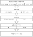
도 1은 본 발명의 일 실시예에 따른 건축 구조물의 지학롱간 및 기초 터파기를 위한 3차원 지형 데이터 생성 시스템의 개략적인 블록도.
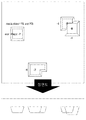
도 2는 건축 기초 터파기 영역의 변환 시작 평면도.
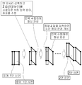
도 3 내지 도 7은 내부 솔리드 형성의 기본 개념을 도시한 도면.
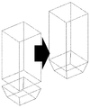
도 8은 내부 솔리드와 상부 솔리드가 결합되는 예가 도시된 도면.
도 9는 솔리드를 순서대로 제거하는 로직이 도시된 도면.
도 10은 하부 높이에 따라 정렬된 결과가 도시된 출력 화면의 예.
도 11은 3차원 지형 추출부가 불필요한 선을 제거하기 위한 로직이 도시된 도면.
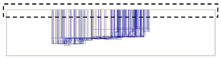
도 12는 가상 공간 상단에서 제거될 객체를 선정하기 위해 형성된 범위가 도시된 도면.
도 13은 불필요한 선 제거 실행 이후 추출된 3차원 지형이 도시된 도면.
도 14는 본 발명의 일 실시예에 따른 건축 구조물의 지학롱간 및 기초 터파기를 위한 3차원 지형 데이터 생성 방법을 수행하기 위한 개략적인 흐름도.
도 15는 도 14에 따라 진행되는 구체적인 과정이 도시된 출력 화면.
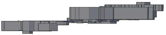
도 16 및 도 17은 각각 완성된 3차원 도면의 평면도 및 사시도.
도 18은 부지 경계부 사면 및 소단 처리의 워크플로우를 도시한 도면.
도 19는 도 18에서 폴리선을 통해 사용자 입력이 수행되는 과정이 도시된 도면.
도 20은 도 18의 로직 실행 화면.
도 21 내지 도 23은 도 18의 과정에 의해 부지 경계부 사면 및 소단 처리 결과가 도시된 도면.1 is a schematic block diagram of a three-dimensional terrain data generation system for long-distance and ground breaking of an architectural structure according to an embodiment of the present invention.
Fig. 2 is a plan view of the start of transformation of the foundation foundation.
3 to 7 are views showing the basic concept of forming an internal solid.
8 is a view showing an example in which the inner solid and the upper solid are combined.
9 is a diagram illustrating logic to remove solids in order.
10 is an example of an output screen showing results sorted according to a lower height.
11 is a diagram illustrating logic for removing unnecessary lines from the 3D terrain extraction unit.
12 is a view showing a range formed to select an object to be removed from the top of the virtual space.
13 is a view showing 3D terrain extracted after unnecessary line removal.
14 is a schematic flow chart for performing a method for generating 3D terrain data for geological longing and foundation breaking of an architectural structure according to an embodiment of the present invention.
15 is an output screen showing a specific process proceeding according to FIG. 14.
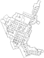
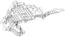
16 and 17 are plan and perspective views, respectively, of a completed three-dimensional drawing.
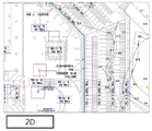
Fig. 18 is a diagram showing a workflow of the site boundary slope and cut processing.
19 is a diagram illustrating a process in which user input is performed through a polyline in FIG. 18.
20 is a logic execution screen of FIG. 18;
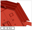
21 to 23 are diagrams showing the results of the slope and cut processing of the site boundary by the process of FIG.
이하, 첨부된 도면을 참조하여 본 발명의 바람직한 실시예를 설명한다. Hereinafter, preferred embodiments of the present invention will be described with reference to the accompanying drawings.
도 1은 본 발명의 일 실시예에 따른 건축 구조물의 지학롱간 및 기초 터파기를 위한 3차원 지형 데이터 생성 시스템의 개략적인 블록도이다. 도 1에서, 건축 구조물의 지학롱간 및 기초 터파기를 위한 3차원 지형 데이터 생성 시스템(100)은 설계 정보 획득부(110), 가상 공간 생성부(120), 내부 솔리드 형성부(130), 솔리드 제거부(140), 및 3차원 지형 추출부(150), 및 경계부 사면 및 소단 형성부(160)를 포함하며, 3차원 지형 추출부(150)는 다시 개별 객체 변환부(152) 및 객체 제거부(154)를 포함한다.1 is a schematic block diagram of a three-dimensional terrain data generation system for long haul and foundation digging of a building structure according to an embodiment of the present invention. In FIG. 1, the 3D terrain
도 1에서 건축 구조물의 지학롱간 및 기초 터파기를 위한 3차원 지형 데이터 생성 시스템(100)의 각 구성 요소들은 하드웨어만으로도 구현될 수 있지만, 하드웨어 및 하드웨어상에서 동작하는 소프트웨어로 함께 구현하는 것이 일반적일 것이다.In FIG. 1, each component of the 3D terrain
설계 정보 획득부(110)는 2차원 설계 정보로부터 건축 기초 터파기 영역 전체 및 건축 기초 터파기 영역 내부에 위치하는 내부 도형들의 평면 형상 정보 및 높이 정보를 획득한다. 도 2는 건축 기초 터파기 영역의 변환 시작 평면도이다. 도 2의 평면도에서 건축 기초 터파기 영역의 전체 및 영역 내부에 위치하는 내부 도형들의 평면 형상을 확인할 수 있다. The design
가상 공간 생성부(120)는 획득된 평면 형상 정보 및 높이 정보를 이용하여 건축 기초 터파기 영역 전체를 포함할 수 있는 3차원 가상 공간을 생성한다. 가상 공간은 터파기 영역 전체를 내부에 포함하기만 하면 되므로 형상에 제한은 없으나 직육면체 형상인 것이 일반적일 것이다. 가상 공간은 입력된 설계 정보에 의해 자동으로 생성될 수도 있으며, 사용자에 의해 입력된 위치나 크기 입력에 의해 생성될 수도 있다.The virtual
내부 솔리드 형성부(130)는 가상 공간 내에 내부 도형들의 평면 형상 정보 및 높이 정보를 이용하여 입체 공간인 내부 솔리드를 형성한다. 이때, 내부 솔리드는 상부의 면적이 하부의 면적보다 크게 형성될 수 있다.The inner solid forming
도 3 내지 도 7은 내부 솔리드 형성의 기본 개념을 도시한 도면이다. 도 3에는 내부 도형의 평면 형상이 사각형인 경우의 예가 도시되어 있다. 도 3에서 내부 솔리드는 상단이 -4, 하단이 -7의 높이를 가지고 있어, 상단이 10, 하단이 -10인 가상 공간 내부에 형성되는 것을 확인할 수 있다.3 to 7 are diagrams showing the basic concept of forming an internal solid. FIG. 3 shows an example in which the internal shape has a rectangular planar shape. In FIG. 3, the inner solid has a height of -4 and a bottom of -7, so it can be seen that the top of the inner solid is formed in a virtual space having a top of 10 and a bottom of -10.
또한, 내부 솔리드의 하부의 면적이 상부의 면적보다 좁게 형성된 것을 확인할 수 있는데, 면적의 좁은 정도는 사용자 등에 의해 미리 설정된 수치나 기울기를 이용하여 조정될 수 있다.In addition, it can be seen that the area of the lower portion of the inner solid is formed narrower than the area of the upper portion, and the narrowness of the area can be adjusted using a preset value or slope by a user or the like.
도 4에는 내부 도형의 평면 형상이 정형화되지 않은 다각형인 경우의 예가 도시되어 있으며, 특히, 도 5에는 하단의 높이가 서로 다른 경우의 예가 도시되어 있다. 또한, 도 6 및 도 7에는 도 3 내지 도 5에 도시된 다양한 모양의 내부 도형들이 가상 공간 내에 함께 위치하는 예가 도시되어 있다.FIG. 4 shows an example in which the planar shape of the internal figure is an unformed polygon, and in particular, FIG. 5 shows an example in which the heights of the lower ends are different. In addition, FIGS. 6 and 7 illustrate examples in which internal shapes of various shapes shown in FIGS. 3 to 5 are located together in a virtual space.
솔리드 형성부(130)는 내부 솔리드 상부로부터 가상 공간의 상부까지 연장되는 상부 솔리드를 더 형성할 수 있으며, 형성된 내부 솔리드와 상부 솔리드를 하나의 결합 솔리드로 결합할 수 있다. 이와 같은 구성에 의하면, 보다 단순하고 효과적으로 가상 공간 내부에 건축 기초 터파기 영역의 3D 지형을 형성할 수 있게 된다. The solid forming
도 8은 내부 솔리드와 상부 솔리드가 결합되는 예가 도시된 도면이다. 예를 들어, CAD 프로그램의 불린 교집합(Booleab Union) 기능 등을 이용하여 내부 솔리드와 상부 솔리드를 결합할 수 있다.8 is a diagram illustrating an example in which an inner solid and an upper solid are combined. For example, you can combine the inner solid and the upper solid by using the Booleab Union function of the CAD program.
솔리드 제거부(140)는 생성된 가상 공간에서 내부 솔리드를 제거한다. 이때, 솔리드의 제거는 하부의 높이가 가장 낮은 솔리드로부터 먼저 수행될 수 있다. 이와 같은 구성에 의하면, 생성되는 3D 도면의 여러 레벨에서의 불필요한 선들을 제거할 수 있게 된다. 도 9는 솔리드를 순서대로 제거하는 로직이 도시된 도면이고, 도 10은 하부 높이에 따라 정렬된 결과가 도시된 출력 화면의 예이다.The
개별 객체 변환부(152)는 결합 솔리드가 제거된 가상 공간을 형성하는 성분들을 분해하여 개별 객체로 변환하고, 객체 제거부(154)는 개별 객체 중 가상 공간의 상단으로부터 미리 설정된 범위 이내에 일부 이상이 포함된 객체를 제거한다. 이와 같은 구성에 의하면, 가상 공간을 포함한 3차원 도면에서 불필요한 선을 제거함으로써 3D 지형 부분만을 추출할 수 있게 된다.The individual
도 11은 3차원 지형 추출부가 불필요한 선을 제거하기 위한 로직이 도시된 도면이고, 도 12는 가상 공간 상단에서 제거될 객체를 선정하기 위해 형성된 범위가 도시된 도면이며, 도 13은 불필요한 선 제거 실행 이후 추출된 3차원 지형이 도시된 도면이다. FIG. 11 is a diagram illustrating logic for removing unnecessary lines from the 3D terrain extraction unit, FIG. 12 is a diagram illustrating a range formed to select an object to be removed from the top of virtual space, and FIG. 13 is executing unnecessary line removal The extracted 3D terrain is then shown.
도 14는 본 발명의 일 실시예에 따른 건축 구조물의 지학롱간 및 기초 터파기를 위한 3차원 지형 데이터 생성 방법을 수행하기 위한 개략적인 흐름도이고, 도 15는 도 14에 따라 진행되는 구체적인 과정이 도시된 출력 화면이고, 도 16 및 도 17은 각각 완성된 3차원 도면의 평면도 및 사시도이다.FIG. 14 is a schematic flowchart for performing a method for generating 3D terrain data for geological longing and foundation breaking of an architectural structure according to an embodiment of the present invention, and FIG. 15 shows a specific process according to FIG. 14. It is an output screen, and FIGS. 16 and 17 are plan and perspective views, respectively, of a completed 3D drawing.
도 14 및 도 15에 도시된 과정은 AUTODESK AUTOCAD 프로그램을 기반으로 3rd Party Add-in Program의 형태로 제공되어, 범용 캐드 사용자이면 누구나 쉽게 활용할 수 있도록 구현될 수 있다. 생성된 3차원 지형 데이터는 다양한 형태로 제공될 수 있으며, 도 15에 도시된 바와 같이, 3차원 와이어프레임(Wire frame)의 형태로 제공될 수도 있다.14 and 15 are provided in the form of a 3 rd Party Add-in Program based on the AUTODESK AUTOCAD program, and can be implemented to be easily utilized by anyone with a general purpose CAD user. The generated 3D terrain data may be provided in various forms, and as illustrated in FIG. 15, may be provided in the form of a 3D wire frame.
보다 구체적인 예를 들어 다시 설명하자면, 건축 기초 구조물의 터파기는 솔리드(Solid)의 Subtract 불린연산(Boolean)을 활용하여 가상공간의 큰 솔리드에서 다각형 기초형상의 상/하단 레벨 속성과 기울기 값을 이용한 솔리드 형상을 순차적으로 제거하는 방식으로 3차원 면을 생성할 수 있다.As a more specific example, the destruction of the architectural foundation structure utilizes the subtract Boolean of the solid (Solid) and the solid using the polygonal top/bottom level property and the slope value in the large solid in the virtual space. Three-dimensional faces can be created by sequentially removing shapes.
건축 기초 터파기 모듈은 4각형 또는 다중 폴리선 형상의 하단높이와 상단높이 및 비율 또는 거리값을 입력하여 전체 건축 기초 터파기 3D 형상을 일괄적으로 생성할 수 있다.The building foundation digging module can collectively generate the entire building foundation digging 3D shape by inputting the bottom height and the top height and ratio or distance values of a quadrangular or multi-polyline shape.
건축 기초 구조물은 역피라미드 형상의 모양으로 터파기 하단높이와 상단높이 값을 가지고 있으며, 서로 근접해 있을 경우 형상이 겹치는 부분에 대한 처리가 필요하다. 이를 처리하기 위한 로직은 가상의 사각형 솔리드에서 낮은 레벨의 기초부터 순차적으로 감(Subtract)하는 방식으로 대지의 크기, 기초 형상, 두 개 이상의 레벨이 다른 겹친 형상도 완성할 수 있다.The basic structure of the building is the shape of the inverted pyramid shape, and has the lower height and upper height values of the trench, and if they are close to each other, it is necessary to process the overlapping shapes. The logic for processing this can be completed by subtracting from the base of the low level in the virtual rectangular solid in order to complete the size of the site, the basic shape, and the overlapping shape with two or more different levels.
경계부 사면 및 소단 형성부(160)는 2차원 설계 정보로부터 건축 기초 터파기 영역의 부지 경계부 사면 및 소단의 3차원 지형 데이터를 생성한다. 이와 같은 구성에 의하면, 주거단지나 산업단지 등 대규모 사업부지 조성시에 설치가 필요한 경계부 사면 또는 옹벽 구조물에 대해서도 사면 조성 공사용 3차원 지형 데이터를 용이하게 생성할 수 있게 된다.The boundary slope and the small
즉, 2차원 설계 정보로 부터 사면/소단의 형상 정보 및 높이 정보를 획득하여 3D 데이터의 생성이 가능하게 되고, ICT 기술의 현장 적용시 이 데이터의 활용이 가능하게 된다.That is, it is possible to generate 3D data by acquiring the shape information and height information of the slope/small plate from the 2D design information, and to utilize this data when applying ICT technology in the field.
도 18은 부지 경계부 사면 및 소단 처리의 워크플로우를 도시한 도면이고, 도 19는 도 18에서 폴리선을 통해 사용자 입력이 수행되는 과정이 도시된 도면이고, 도 20은 도 18의 로직 실행 화면이며, 도 21 내지 도 23은 도 18의 과정에 의해 부지 경계부 사면 및 소단 처리 결과가 도시된 도면이다. FIG. 18 is a view showing a workflow of processing a slope and an end of a site boundary, FIG. 19 is a view showing a process in which user input is performed through a polyline in FIG. 18, and FIG. 20 is a logic execution screen of FIG. 18, 21 to 23 are views illustrating the results of the slope and cut processing of the site boundary by the process of FIG. 18.
본 발명이 비록 일부 바람직한 실시예에 의해 설명되었지만, 본 발명의 범위는 이에 의해 제한되어서는 아니 되고, 특허청구범위에 의해 뒷받침되는 상기 실시예의 변형이나 개량에도 미쳐야 할 것이다.Although the invention has been described in terms of some preferred embodiments, the scope of the invention should not be limited by this, but should also extend to variations or improvements of the embodiments supported by the claims.
100: 건축 구조물의 지학롱간 및 기초 터파기를 위한 3차원 지형 데이터 생성 시스템
110: 설계 정보 획득부
120: 가상 공간 생성부
130: 내부 솔리드 형성부
140: 솔리드 제거부
150: 3차원 지형 추출부
152: 개별 객체 변환부
154: 객체 제거부
160: 경계부 사면 및 소단 형성부100: 3D terrain data generation system for long haul and foundation breaking of building structures
110: design information acquisition unit
120: virtual space creation unit
130: internal solid formation
140: solid removal
150: 3D terrain extraction unit
152: individual object conversion unit
154: object removal unit
160: boundary slope and small end forming part
Claims (15)
상기 평면 형상 정보 및 높이 정보를 이용하여 상기 건축 기초 터파기 영역 전체를 포함할 수 있는 3차원 가상 공간을 생성하는 가상 공간 생성부;
상기 가상 공간 내에 상기 내부 도형들의 평면 형상 정보 및 높이 정보를 이용하여 입체 공간인 내부 솔리드를 형성하는 내부 솔리드 형성부; 및
상기 가상 공간에서 상기 내부 솔리드를 제거하는 솔리드 제거부를 포함하는 것을 특징으로 하는 건축 구조물의 지학롱간 및 기초 터파기를 위한 3차원 지형 데이터 생성 시스템.
A design information acquiring unit for acquiring planar shape information and height information of internal figures located in the building foundation trench area corresponding to the entire building foundation trench area and the underground space of the building structure from the 2D design information;
A virtual space generator for generating a three-dimensional virtual space that may include the entire foundation foundation area using the planar shape information and height information;
An inner solid forming unit forming an inner solid that is a three-dimensional space by using planar shape information and height information of the inner figures in the virtual space; And
And a solid removal unit for removing the internal solids from the virtual space.
상기 솔리드 형성부는 상기 내부 솔리드 상부로부터 상기 가상 공간의 상부까지 연장되는 상부 솔리드를 더 형성하는 것을 특징으로 하는 건축 구조물의 지학롱간 및 기초 터파기를 위한 3차원 지형 데이터 생성 시스템.
The method according to claim 1,
The solid forming unit further forms an upper solid that extends from the upper portion of the inner solid to the upper portion of the virtual space.
상기 솔리드 형성부는 상기 내부 솔리드와 상기 상부 솔리드를 하나의 결합 솔리드로 결합하는 것을 특징으로 하는 건축 구조물의 지학롱간 및 기초 터파기를 위한 3차원 지형 데이터 생성 시스템.
The method according to claim 2,
The solid forming unit is a three-dimensional terrain data generation system for long-distance and ground breaking of an architectural structure, characterized in that the inner solid and the upper solid are combined into one combined solid.
상기 내부 솔리드는 상부의 면적이 하부의 면적보다 크게 형성되는 것을 특징으로 하는 건축 구조물의 지학롱간 및 기초 터파기를 위한 3차원 지형 데이터 생성 시스템.
The method according to claim 3,
The inner solid is a three-dimensional terrain data generation system for the foundation and ground breaking of the building structure, characterized in that the upper area is formed larger than the lower area.
상기 결합 솔리드가 제거된 가상 공간을 형성하는 성분들을 분해하여 개별 객체로 변환하는 개별 객체 변환부; 및
상기 개별 객체 중 상기 가상 공간의 상단으로부터 미리 설정된 범위 이내에 일부 이상이 포함된 객체를 제거하는 객체 제거부를 포함하는 3차원 지형 추출부를 더 포함하는 것을 특징으로 하는 건축 구조물의 지학롱간 및 기초 터파기를 위한 3차원 지형 데이터 생성 시스템.
The method according to claim 4,
An individual object converting unit that decomposes components that form the virtual space from which the combined solid is removed and converts them into individual objects; And
A three-dimensional terrain extracting unit including an object removing unit for removing an object including a part or more within a predetermined range from the top of the virtual space among the individual objects, further comprising: 3D terrain data generation system.
상기 솔리드의 제거는 하부의 높이가 가장 낮은 솔리드로부터 먼저 수행되는 것을 특징으로 하는 건축 구조물의 지학롱간 및 기초 터파기를 위한 3차원 지형 데이터 생성 시스템.
The method according to claim 5,
The removal of the solid is a three-dimensional terrain data generation system for long-distance and foundation digging of a building structure, characterized in that the lower height is performed first from the lowest solid.
상기 2차원 설계 정보로부터 상기 건축 기초 터파기 영역의 부지 경계부 사면 및 소단의 3차원 지형 데이터를 생성하는 경계부 사면 및 소단 형성부를 더 포함하는 것을 특징으로 하는 건축 구조물의 지학롱간 및 기초 터파기를 위한 3차원 지형 데이터 생성 시스템.
The method according to claim 6,
3 for ground breaking and foundation breaking of a building structure, characterized in that it further comprises a boundary slope and a column formation unit for generating 3D terrain data of the site boundary slopes and columns of the building foundation trench area from the 2D design information. Dimensional Terrain Data Generation System.
2차원 설계 정보로부터 건축 기초 터파기 영역 전체 및 상기 건축 기초 터파기 영역 내부에 위치하는 내부 도형들의 평면 형상 정보 및 높이 정보를 획득하는 설계 정보 획득 단계;
상기 평면 형상 정보 및 높이 정보를 이용하여 상기 건축 기초 터파기 영역 전체를 포함할 수 있는 3차원 가상 공간을 생성하는 가상 공간 생성 단계;
상기 가상 공간 내에 상기 내부 도형들의 평면 형상 정보 및 높이 정보를 이용하여 입체 공간인 내부 솔리드를 형성하는 솔리드 형성 단계; 및
상기 가상 공간에서 상기 내부 솔리드를 제거하는 솔리드 제거 단계를 포함하는 것을 특징으로 하는 건축 구조물의 지학롱간 및 기초 터파기를 위한 3차원 지형 데이터 생성 방법.
A method for generating three-dimensional terrain data performed by a three-dimensional terrain data generation system for long-term and basic excavation of architectural structures,
A design information acquiring step of acquiring, from two-dimensional design information, planar shape information and height information of the entire architectural foundation trench area and internal figures located inside the architectural foundation trench area;
A virtual space generation step of generating a three-dimensional virtual space that may include the entire construction foundation trench area using the planar shape information and height information;
A solid forming step of forming an inner solid, which is a three-dimensional space, by using planar shape information and height information of the inner figures in the virtual space; And
And removing solids from the virtual spaces, removing solids from the virtual space.
상기 솔리드 형성 단계는 상기 내부 솔리드 상부로부터 상기 가상 공간의 상부까지 연장되는 상부 솔리드를 더 형성하는 것을 특징으로 하는 건축 구조물의 지학롱간 및 기초 터파기를 위한 3차원 지형 데이터 생성 방법.
The method according to claim 8,
The solid forming step further comprises forming an upper solid extending from the upper portion of the inner solid to the upper portion of the virtual space.
상기 솔리드 형성 단계는 상기 내부 솔리드와 상기 상부 솔리드를 하나의 결합 솔리드로 결합하는 것을 특징으로 하는 건축 구조물의 지학롱간 및 기초 터파기를 위한 3차원 지형 데이터 생성 방법.
The method according to claim 9,
The solid forming step is a method for generating three-dimensional terrain data for long-term and basic excavation of an architectural structure, characterized in that the inner solid and the upper solid are combined into one combined solid.
상기 내부 솔리드는 상부의 면적이 하부의 면적보다 크게 형성되는 것을 특징으로 하는 건축 구조물의 지학롱간 및 기초 터파기를 위한 3차원 지형 데이터 생성 방법.
The method according to claim 10,
The inner solid is a method of generating three-dimensional terrain data for geological interception and foundation digging of a building structure, characterized in that the upper area is formed larger than the lower area.
상기 결합 솔리드가 제거된 가상 공간을 형성하는 성분들을 분해하여 개별 객체로 변환하는 개별 객체 변환 단계; 및
상기 개별 객체 중 상기 가상 공간의 상단으로부터 미리 설정된 범위 이내에 일부 이상이 포함된 객체를 제거하는 객체 제거 단계를 포함하는 3차원 지형 추출 단계를 더 포함하는 것을 특징으로 하는 건축 구조물의 지학롱간 및 기초 터파기를 위한 3차원 지형 데이터 생성 방법.
The method according to claim 11,
An individual object conversion step of decomposing components forming the virtual space from which the combined solid is removed and converting them into individual objects; And
And a 3D terrain extraction step of removing the object including a part or more within a predetermined range from the top of the virtual space among the individual objects. 3D terrain data generation method for flags.
상기 솔리드의 제거는 하부의 높이가 가장 낮은 솔리드로부터 먼저 수행되는 것을 특징으로 하는 건축 구조물의 지학롱간 및 기초 터파기를 위한 3차원 지형 데이터 생성 방법.
The method according to claim 12,
The method of generating three-dimensional terrain data for long haul and foundation digging of a building structure, characterized in that the removal of the solid is performed first from the solid having the lowest height.
상기 2차원 설계 정보로부터 상기 건축 기초 터파기 영역의 부지 경계부 사면 및 소단의 3차원 지형 데이터를 생성하는 경계부 사면 및 소단 형성 단계를 더 포함하는 것을 특징으로 하는 건축 구조물의 지학롱간 및 기초 터파기를 위한 3차원 지형 데이터 생성 방법.
The method according to claim 13,
And forming a boundary slope and a column to generate 3D terrain data of the boundary and slope of the site boundary of the building foundation trench area from the 2D design information. 3D terrain data generation method.
A recording medium in which a computer-readable program for executing the method of claim 8 is recorded.
Priority Applications (1)
| Application Number | Priority Date | Filing Date | Title |
|---|---|---|---|
| KR1020180165581A KR102156641B1 (en) | 2018-12-19 | 2018-12-19 | System and method of generating 3d topography data for construction basic excavation, and a recording medium having computer readable program for executing the method |
Applications Claiming Priority (1)
| Application Number | Priority Date | Filing Date | Title |
|---|---|---|---|
| KR1020180165581A KR102156641B1 (en) | 2018-12-19 | 2018-12-19 | System and method of generating 3d topography data for construction basic excavation, and a recording medium having computer readable program for executing the method |
Publications (2)
| Publication Number | Publication Date |
|---|---|
| KR20200076458A true KR20200076458A (en) | 2020-06-29 |
| KR102156641B1 KR102156641B1 (en) | 2020-09-16 |
Family
ID=71401107
Family Applications (1)
| Application Number | Title | Priority Date | Filing Date |
|---|---|---|---|
| KR1020180165581A KR102156641B1 (en) | 2018-12-19 | 2018-12-19 | System and method of generating 3d topography data for construction basic excavation, and a recording medium having computer readable program for executing the method |
Country Status (1)
| Country | Link |
|---|---|
| KR (1) | KR102156641B1 (en) |
Cited By (2)
| Publication number | Priority date | Publication date | Assignee | Title |
|---|---|---|---|---|
| CN115147440A (en) * | 2022-07-12 | 2022-10-04 | 中国建筑西南设计研究院有限公司 | Automatic basic slope-making line generation method based on surface area cutting method |
| CN116644505A (en) * | 2023-07-26 | 2023-08-25 | 长江勘测规划设计研究有限责任公司 | Rapid design method for drainage groove of barrier lake |
Citations (4)
| Publication number | Priority date | Publication date | Assignee | Title |
|---|---|---|---|---|
| JPS6224659B2 (en) | 1979-11-14 | 1987-05-29 | Nippon Denso Kk | |
| JP2007272403A (en) * | 2006-03-30 | 2007-10-18 | Toshiba Corp | Cad device and cad method |
| KR101165130B1 (en) * | 2009-04-22 | 2012-07-12 | (주)덕성알파이엔지 | System of automatically calculating and displaying amount of earthwork materials based on three dimensional design |
| KR101767230B1 (en) * | 2017-02-28 | 2017-08-10 | 플랜트에셋 주식회사 | Unification management method of 3D CAD modeling data for plant engineering |
-
2018
- 2018-12-19 KR KR1020180165581A patent/KR102156641B1/en active IP Right Grant
Patent Citations (4)
| Publication number | Priority date | Publication date | Assignee | Title |
|---|---|---|---|---|
| JPS6224659B2 (en) | 1979-11-14 | 1987-05-29 | Nippon Denso Kk | |
| JP2007272403A (en) * | 2006-03-30 | 2007-10-18 | Toshiba Corp | Cad device and cad method |
| KR101165130B1 (en) * | 2009-04-22 | 2012-07-12 | (주)덕성알파이엔지 | System of automatically calculating and displaying amount of earthwork materials based on three dimensional design |
| KR101767230B1 (en) * | 2017-02-28 | 2017-08-10 | 플랜트에셋 주식회사 | Unification management method of 3D CAD modeling data for plant engineering |
Cited By (4)
| Publication number | Priority date | Publication date | Assignee | Title |
|---|---|---|---|---|
| CN115147440A (en) * | 2022-07-12 | 2022-10-04 | 中国建筑西南设计研究院有限公司 | Automatic basic slope-making line generation method based on surface area cutting method |
| CN115147440B (en) * | 2022-07-12 | 2024-04-19 | 中国建筑西南设计研究院有限公司 | Automatic generation method of basic slope line based on surface area clipping method |
| CN116644505A (en) * | 2023-07-26 | 2023-08-25 | 长江勘测规划设计研究有限责任公司 | Rapid design method for drainage groove of barrier lake |
| CN116644505B (en) * | 2023-07-26 | 2023-10-13 | 长江勘测规划设计研究有限责任公司 | Rapid design method for drainage groove of barrier lake |
Also Published As
| Publication number | Publication date |
|---|---|
| KR102156641B1 (en) | 2020-09-16 |
Similar Documents
| Publication | Publication Date | Title |
|---|---|---|
| CN110750864B (en) | Dam break flood demonstration early warning method and platform based on BIM technology | |
| CN106408604A (en) | Filtering method and device for point cloud data | |
| KR100928836B1 (en) | Excavator Excavation System and Excavation Method by Excavator | |
| KR101425576B1 (en) | Method for acquiring and processing a three-dimensional data to product a precise wide-area scale model | |
| KR20200076458A (en) | System and method of generating 3d topography data for construction basic excavation, and a recording medium having computer readable program for executing the method | |
| CN108108563B (en) | Cross-platform hydrodynamics modeling method based on BIM and GIS technology | |
| EP3751318A1 (en) | Three-dimensional ground model generation and automated earthwork target model generation system based on parameter input | |
| CN109614727A (en) | Ultrasonic wave added aperture drilling grinding wheel parametric modeling method based on ABAQUS software | |
| CN113779670A (en) | Method and system for achieving double-control modeling of Revit pile foundation based on Dynamo | |
| CN116229003A (en) | Three-dimensional model monomerization rapid construction method based on multi-source data | |
| KR101754294B1 (en) | Bim data transform apparatus for ununiformed beam member and the method thereof | |
| KR102046112B1 (en) | Apparatus for providing 3d terrain and facility data using online map open api and method thereof | |
| KR20120128395A (en) | System for integrating riverside land dem with protected land dem | |
| KR102130922B1 (en) | 3D Solid Cut / Fill Terrain and Corridor Structure Objects by Station by Automatic Extraction of Station and Object Information by Location of 3D Surface Terrain and Corridor Structures Automatic conversion and quantity automatic generation system and method | |
| CN111260714A (en) | Flood disaster assessment method, device, equipment and computer storage medium | |
| JP5320576B1 (en) | Highland leveling program, dynamic link library and landscape examination device | |
| CN109583102A (en) | A kind of optimization method, the apparatus and system of reinforced concrete support design | |
| CN106192980B (en) | A kind of method of the closely knit sandstone ground of dither | |
| KR100486670B1 (en) | 3-dimensional graphic data producing system and the method using 2-dimensional graphic drawings | |
| JP5519575B2 (en) | Plant construction process creation support system, plant construction process creation support method and program | |
| Boggus et al. | Prismfields: A framework for interactive modeling of three dimensional caves | |
| CN111753346B (en) | Linear member profile generating method, revit platform and storage medium | |
| CN110222457B (en) | Construction method of existing structure and newly-built primary support structure with existing structure closely attached | |
| JP2021140285A (en) | Mesh model generation apparatus and mesh model generation method | |
| JP2009249929A (en) | Three-dimensional display for excavation construction, and excavation construction display program |
Legal Events
| Date | Code | Title | Description |
|---|---|---|---|
| E701 | Decision to grant or registration of patent right | ||
| GRNT | Written decision to grant |