KR20200073042A - Battery module - Google Patents
Battery module Download PDFInfo
- Publication number
- KR20200073042A KR20200073042A KR1020180161298A KR20180161298A KR20200073042A KR 20200073042 A KR20200073042 A KR 20200073042A KR 1020180161298 A KR1020180161298 A KR 1020180161298A KR 20180161298 A KR20180161298 A KR 20180161298A KR 20200073042 A KR20200073042 A KR 20200073042A
- Authority
- KR
- South Korea
- Prior art keywords
- bus bar
- battery module
- safety
- battery
- volume expansion
- Prior art date
Links
- 229920005989 resin Polymers 0.000 claims abstract description 25
- 239000011347 resin Substances 0.000 claims abstract description 25
- 239000004020 conductor Substances 0.000 claims abstract description 16
- 239000000853 adhesive Substances 0.000 claims abstract description 13
- 230000001070 adhesive effect Effects 0.000 claims abstract description 13
- 229910052751 metal Inorganic materials 0.000 claims description 6
- 239000002184 metal Substances 0.000 claims description 6
- 239000000843 powder Substances 0.000 claims description 6
- 239000000463 material Substances 0.000 claims description 5
- ZQKXQUJXLSSJCH-UHFFFAOYSA-N melamine cyanurate Chemical compound NC1=NC(N)=NC(N)=N1.O=C1NC(=O)NC(=O)N1 ZQKXQUJXLSSJCH-UHFFFAOYSA-N 0.000 claims description 5
- OKTJSMMVPCPJKN-UHFFFAOYSA-N Carbon Chemical compound [C] OKTJSMMVPCPJKN-UHFFFAOYSA-N 0.000 claims description 3
- 238000004806 packaging method and process Methods 0.000 claims description 2
- 230000000903 blocking effect Effects 0.000 abstract description 6
- 230000002159 abnormal effect Effects 0.000 abstract description 5
- 239000007789 gas Substances 0.000 description 6
- PXHVJJICTQNCMI-UHFFFAOYSA-N Nickel Chemical compound [Ni] PXHVJJICTQNCMI-UHFFFAOYSA-N 0.000 description 3
- 238000005979 thermal decomposition reaction Methods 0.000 description 3
- 229910052782 aluminium Inorganic materials 0.000 description 2
- XAGFODPZIPBFFR-UHFFFAOYSA-N aluminium Chemical compound [Al] XAGFODPZIPBFFR-UHFFFAOYSA-N 0.000 description 2
- 230000008901 benefit Effects 0.000 description 2
- 230000008859 change Effects 0.000 description 2
- 230000008878 coupling Effects 0.000 description 2
- 238000010168 coupling process Methods 0.000 description 2
- 238000005859 coupling reaction Methods 0.000 description 2
- 230000006872 improvement Effects 0.000 description 2
- 238000003466 welding Methods 0.000 description 2
- IJGRMHOSHXDMSA-UHFFFAOYSA-N Atomic nitrogen Chemical compound N#N IJGRMHOSHXDMSA-UHFFFAOYSA-N 0.000 description 1
- BQCADISMDOOEFD-UHFFFAOYSA-N Silver Chemical compound [Ag] BQCADISMDOOEFD-UHFFFAOYSA-N 0.000 description 1
- ATJFFYVFTNAWJD-UHFFFAOYSA-N Tin Chemical compound [Sn] ATJFFYVFTNAWJD-UHFFFAOYSA-N 0.000 description 1
- 239000011149 active material Substances 0.000 description 1
- 230000000712 assembly Effects 0.000 description 1
- 238000000429 assembly Methods 0.000 description 1
- 238000005452 bending Methods 0.000 description 1
- 239000006227 byproduct Substances 0.000 description 1
- 239000011248 coating agent Substances 0.000 description 1
- 238000000576 coating method Methods 0.000 description 1
- 230000007423 decrease Effects 0.000 description 1
- 229910001873 dinitrogen Inorganic materials 0.000 description 1
- 238000003487 electrochemical reaction Methods 0.000 description 1
- 239000003792 electrolyte Substances 0.000 description 1
- 238000004146 energy storage Methods 0.000 description 1
- 239000003822 epoxy resin Substances 0.000 description 1
- -1 for example Substances 0.000 description 1
- 239000002803 fossil fuel Substances 0.000 description 1
- PCHJSUWPFVWCPO-UHFFFAOYSA-N gold Chemical compound [Au] PCHJSUWPFVWCPO-UHFFFAOYSA-N 0.000 description 1
- 229910052737 gold Inorganic materials 0.000 description 1
- 239000010931 gold Substances 0.000 description 1
- WABPQHHGFIMREM-NOHWODKXSA-N lead-200 Chemical compound [200Pb] WABPQHHGFIMREM-NOHWODKXSA-N 0.000 description 1
- 230000004048 modification Effects 0.000 description 1
- 238000012986 modification Methods 0.000 description 1
- 229910052759 nickel Inorganic materials 0.000 description 1
- 229920000647 polyepoxide Polymers 0.000 description 1
- 229910052709 silver Inorganic materials 0.000 description 1
- 239000004332 silver Substances 0.000 description 1
- 239000000126 substance Substances 0.000 description 1
Images
Classifications
-
- H—ELECTRICITY
- H01—ELECTRIC ELEMENTS
- H01M—PROCESSES OR MEANS, e.g. BATTERIES, FOR THE DIRECT CONVERSION OF CHEMICAL ENERGY INTO ELECTRICAL ENERGY
- H01M50/00—Constructional details or processes of manufacture of the non-active parts of electrochemical cells other than fuel cells, e.g. hybrid cells
- H01M50/50—Current conducting connections for cells or batteries
- H01M50/502—Interconnectors for connecting terminals of adjacent batteries; Interconnectors for connecting cells outside a battery casing
- H01M50/521—Interconnectors for connecting terminals of adjacent batteries; Interconnectors for connecting cells outside a battery casing characterised by the material
-
- H01M2/348—
-
- H—ELECTRICITY
- H01—ELECTRIC ELEMENTS
- H01M—PROCESSES OR MEANS, e.g. BATTERIES, FOR THE DIRECT CONVERSION OF CHEMICAL ENERGY INTO ELECTRICAL ENERGY
- H01M10/00—Secondary cells; Manufacture thereof
- H01M10/42—Methods or arrangements for servicing or maintenance of secondary cells or secondary half-cells
-
- H01M2/1072—
-
- H01M2/206—
-
- H—ELECTRICITY
- H01—ELECTRIC ELEMENTS
- H01M—PROCESSES OR MEANS, e.g. BATTERIES, FOR THE DIRECT CONVERSION OF CHEMICAL ENERGY INTO ELECTRICAL ENERGY
- H01M50/00—Constructional details or processes of manufacture of the non-active parts of electrochemical cells other than fuel cells, e.g. hybrid cells
- H01M50/20—Mountings; Secondary casings or frames; Racks, modules or packs; Suspension devices; Shock absorbers; Transport or carrying devices; Holders
- H01M50/204—Racks, modules or packs for multiple batteries or multiple cells
- H01M50/207—Racks, modules or packs for multiple batteries or multiple cells characterised by their shape
- H01M50/209—Racks, modules or packs for multiple batteries or multiple cells characterised by their shape adapted for prismatic or rectangular cells
-
- H—ELECTRICITY
- H01—ELECTRIC ELEMENTS
- H01M—PROCESSES OR MEANS, e.g. BATTERIES, FOR THE DIRECT CONVERSION OF CHEMICAL ENERGY INTO ELECTRICAL ENERGY
- H01M50/00—Constructional details or processes of manufacture of the non-active parts of electrochemical cells other than fuel cells, e.g. hybrid cells
- H01M50/20—Mountings; Secondary casings or frames; Racks, modules or packs; Suspension devices; Shock absorbers; Transport or carrying devices; Holders
- H01M50/204—Racks, modules or packs for multiple batteries or multiple cells
- H01M50/207—Racks, modules or packs for multiple batteries or multiple cells characterised by their shape
- H01M50/211—Racks, modules or packs for multiple batteries or multiple cells characterised by their shape adapted for pouch cells
-
- H—ELECTRICITY
- H01—ELECTRIC ELEMENTS
- H01M—PROCESSES OR MEANS, e.g. BATTERIES, FOR THE DIRECT CONVERSION OF CHEMICAL ENERGY INTO ELECTRICAL ENERGY
- H01M50/00—Constructional details or processes of manufacture of the non-active parts of electrochemical cells other than fuel cells, e.g. hybrid cells
- H01M50/50—Current conducting connections for cells or batteries
- H01M50/502—Interconnectors for connecting terminals of adjacent batteries; Interconnectors for connecting cells outside a battery casing
- H01M50/507—Interconnectors for connecting terminals of adjacent batteries; Interconnectors for connecting cells outside a battery casing comprising an arrangement of two or more busbars within a container structure, e.g. busbar modules
-
- H—ELECTRICITY
- H01—ELECTRIC ELEMENTS
- H01M—PROCESSES OR MEANS, e.g. BATTERIES, FOR THE DIRECT CONVERSION OF CHEMICAL ENERGY INTO ELECTRICAL ENERGY
- H01M50/00—Constructional details or processes of manufacture of the non-active parts of electrochemical cells other than fuel cells, e.g. hybrid cells
- H01M50/50—Current conducting connections for cells or batteries
- H01M50/543—Terminals
- H01M50/552—Terminals characterised by their shape
- H01M50/553—Terminals adapted for prismatic, pouch or rectangular cells
-
- H—ELECTRICITY
- H01—ELECTRIC ELEMENTS
- H01M—PROCESSES OR MEANS, e.g. BATTERIES, FOR THE DIRECT CONVERSION OF CHEMICAL ENERGY INTO ELECTRICAL ENERGY
- H01M50/00—Constructional details or processes of manufacture of the non-active parts of electrochemical cells other than fuel cells, e.g. hybrid cells
- H01M50/50—Current conducting connections for cells or batteries
- H01M50/572—Means for preventing undesired use or discharge
- H01M50/574—Devices or arrangements for the interruption of current
- H01M50/581—Devices or arrangements for the interruption of current in response to temperature
-
- H—ELECTRICITY
- H01—ELECTRIC ELEMENTS
- H01M—PROCESSES OR MEANS, e.g. BATTERIES, FOR THE DIRECT CONVERSION OF CHEMICAL ENERGY INTO ELECTRICAL ENERGY
- H01M2200/00—Safety devices for primary or secondary batteries
-
- H—ELECTRICITY
- H01—ELECTRIC ELEMENTS
- H01M—PROCESSES OR MEANS, e.g. BATTERIES, FOR THE DIRECT CONVERSION OF CHEMICAL ENERGY INTO ELECTRICAL ENERGY
- H01M2200/00—Safety devices for primary or secondary batteries
- H01M2200/10—Temperature sensitive devices
-
- H—ELECTRICITY
- H01—ELECTRIC ELEMENTS
- H01M—PROCESSES OR MEANS, e.g. BATTERIES, FOR THE DIRECT CONVERSION OF CHEMICAL ENERGY INTO ELECTRICAL ENERGY
- H01M2220/00—Batteries for particular applications
- H01M2220/20—Batteries in motive systems, e.g. vehicle, ship, plane
-
- Y—GENERAL TAGGING OF NEW TECHNOLOGICAL DEVELOPMENTS; GENERAL TAGGING OF CROSS-SECTIONAL TECHNOLOGIES SPANNING OVER SEVERAL SECTIONS OF THE IPC; TECHNICAL SUBJECTS COVERED BY FORMER USPC CROSS-REFERENCE ART COLLECTIONS [XRACs] AND DIGESTS
- Y02—TECHNOLOGIES OR APPLICATIONS FOR MITIGATION OR ADAPTATION AGAINST CLIMATE CHANGE
- Y02E—REDUCTION OF GREENHOUSE GAS [GHG] EMISSIONS, RELATED TO ENERGY GENERATION, TRANSMISSION OR DISTRIBUTION
- Y02E60/00—Enabling technologies; Technologies with a potential or indirect contribution to GHG emissions mitigation
- Y02E60/10—Energy storage using batteries
Abstract
Description
본 발명은 전지 모듈에 관한 것으로, 보다 구체적으로 안전성이 개선된 버스바를 포함하는 전지 모듈에 관한 것이다.The present invention relates to a battery module, and more particularly, to a battery module including a bus bar with improved safety.
이차 전지는 제품군에 따른 적용 용이성이 높고, 높은 에너지 밀도 등의 전기적 특성을 가지기 때문에, 휴대용 기기뿐만 아니라 전기적 구동원에 의해 구동하는 전기 자동차 또는 하이브리드 자동차, 전력 저장 장치 등에 보편적으로 응용되고 있다. 이러한 이차 전지는 화석 연료의 사용을 획기적으로 감소시킬 수 있다는 일차적인 장점뿐만 아니라 에너지의 사용에 따른 부산물이 전혀 발생되지 않는다는 점에서 친환경 및 에너지 효율성 제고를 위한 새로운 에너지원으로 주목 받고 있다.Secondary batteries are widely applied to electric vehicles, hybrid vehicles, and power storage devices driven by electric driving sources, as well as portable devices, because of their high ease of application and high electrical energy. This secondary battery is attracting attention as a new energy source for eco-friendliness and energy efficiency improvement, in that not only does not generate any by-products due to the use of energy, as well as a primary advantage that can dramatically reduce the use of fossil fuels.
상기 전기 자동차 등에 적용되는 전지 팩은 고출력을 얻기 위해 복수의 단위 셀을 포함하는 다수의 셀 조립체를 직렬로 연결한 구조를 가지고 있다. 그리고, 상기 단위 셀은 양극 및 음극 집전체, 세퍼레이터, 활물질, 전해액 등을 포함하여 구성 요소들 간의 전기 화학적 반응에 의하여 반복적인 충방전이 가능하다.The battery pack applied to the electric vehicle or the like has a structure in which a plurality of cell assemblies including a plurality of unit cells are connected in series to obtain high output. In addition, the unit cell can be repeatedly charged and discharged by electrochemical reactions between components, including a positive electrode and a negative electrode current collector, a separator, an active material, and an electrolyte.
한편, 근래 에너지 저장원으로서의 활용을 비롯하여 대용량 구조에 대한 필요성이 높아지면서 다수의 이차 전지가 직렬 및/또는 병렬로 연결된 다수의 전지 모듈을 집합시킨 멀티 모듈 구조의 전지팩에 대한 수요가 증가하고 있다.Meanwhile, in recent years, as a need for a large-capacity structure has been increased, including utilization as an energy storage source, a demand for a multi-module structure battery pack in which a plurality of battery modules are connected in series and/or in parallel is increasing. .
복수개의 전지 셀을 직렬/병렬로 연결하여 전지 팩을 구성하는 경우, 적어도 하나의 전지 셀로 이루어지는 전지 모듈을 먼저 구성하고, 이러한 적어도 하나의 전지 모듈을 이용하여 기타 구성 요소를 추가하여 전지 팩을 구성하는 방법이 일반적이다. 상기 전지 팩에 포함되는 전지 모듈의 개수, 또는 전지 모듈에 포함되는 전지 셀의 개수는 요구되는 출력 전압 또는 충방전 용량에 따라 다양하게 설정될 수 있다. 이렇게 설정된 전지 모듈은 상호 적층되는 복수 개의 전지 셀들 및 상기 복수 개의 전지 셀들의 전극 리드들을 전기적으로 연결하는 버스바 를 포함하여 구성된다. When a battery pack is configured by connecting a plurality of battery cells in series/parallel, a battery module composed of at least one battery cell is configured first, and other components are added to configure the battery pack using the at least one battery module. How to do it is common. The number of battery modules included in the battery pack or the number of battery cells included in the battery module may be variously set according to a required output voltage or charge/discharge capacity. The battery module set as described above includes a plurality of battery cells that are stacked with each other and a bus bar that electrically connects the electrode leads of the plurality of battery cells.
이와 같은 중대형 전지 모듈에 있어서 안전성 확보를 위해 전지 셀 내부의 압력이 상승하게 되면 셀 내부의 리드를 녹여 전류를 차단하도록 설계되어 있으나, 셀 내부 압력의 상승 여부에 의해 작동하기 때문에 파우치형 셀일 경우 파우치 변형의 문제가 있다. 이 때문에 중대형 전지 모듈에 있어서도 셀 내부의 온도가 상승할 경우 전류를 차단하여 안정적으로 안전성을 확보할 수 있는 수단의 필요성이 대두되고 있다. In this medium-to-large-sized battery module, when the pressure inside the battery cell rises to ensure safety, it is designed to melt the lead inside the cell to cut off the current, but because it operates by whether the pressure inside the cell rises, the pouch in the case of a pouch type cell There is a problem of deformation. For this reason, even in the middle- or large-sized battery module, there is a need for a means to stably secure safety by blocking current when the temperature inside the cell increases.
본 발명이 해결하고자 하는 과제는, 전지 모듈에 있어서 온도 상승에 따른 열폭주 등의 이상 상황에서 전류를 차단하여 안전성을 확보할 수 있으며 동시에 정상적인 상황에서는 저항이 높지 않아 기존 성능을 동일하게 유지할 수 있는 버스바를 포함하는 전지 모듈을 제공하기 위한 것이다.The problem to be solved by the present invention is to secure the safety by blocking the current in an abnormal situation such as thermal runaway due to temperature rise in the battery module, and at the same time, under normal circumstances, the resistance is not high, so that the existing performance can be kept the same. It is to provide a battery module including a bus bar.
그러나, 본 발명의 실시예들이 해결하고자 하는 과제는 상술한 과제에 한정되지 않고 본 발명에 포함된 기술적 사상의 범위에서 다양하게 확장될 수 있다.However, the problems to be solved by the embodiments of the present invention are not limited to the above-described problems and can be variously extended within the scope of the technical spirit included in the present invention.
본 발명의 일 실시예에 따른 전지 모듈은, 복수의 전지 셀, 및 상기 복수의 전지 셀을 전기적으로 연결하는 버스바를 포함하고, 상기 버스바는 버스바 본체, 및 상기 버스바 본체의 일부에 삽입되어 버스바 본체에 의해 둘러싸여 있는 안전부를 포함하고, 상기 안전부는 부피 팽창 수지, 전도성 물질 및 접착제를 포함한다.The battery module according to an embodiment of the present invention includes a plurality of battery cells, and a bus bar electrically connecting the plurality of battery cells, wherein the bus bar is inserted into a bus bar body and a part of the bus bar body The safety part is enclosed by the busbar body, and the safety part includes a bulk expansion resin, a conductive material and an adhesive.
상기 안전부는 상기 버스바 본체와 동일한 두께를 가질 수 있다.The safety part may have the same thickness as the body of the bus bar.
상기 부피 팽창 수지는 소정 온도 이상의 환경에서 가스를 발생시키는 물질을 포함할 수 있다.The volume expansion resin may include a substance that generates gas in an environment above a predetermined temperature.
상기 부피 팽창 수지는 멜라민 시아누레이트(melamine cyanurate)를 포함할 수 있다.The volume expansion resin may include melamine cyanurate.
상기 안전부는 상기 부피 팽창 수지, 상기 전도성 물질, 및 상기 접착제가 혼합되어 형성될 수 있다.The safety part may be formed by mixing the volume expansion resin, the conductive material, and the adhesive.
상기 소정 온도 이상의 환경에서 부피 팽창 수지에서 가스가 발생하는 것에 의해 상기 안전부의 저항이 상승하여 전류가 차단될 수 있다.In the environment above the predetermined temperature, by generating gas in the volume expansion resin, the resistance of the safety part rises, so that the current may be cut off.
상기 소정 온도 미만의 환경에서 상기 안전부는 상기 전도성 물질에 의해 도전성을 가질 수 있다. In an environment below the predetermined temperature, the safety part may have conductivity by the conductive material.
상기 전도성 물질은 금속 분말 또는 탄소 분말일 수 있다.The conductive material may be metal powder or carbon powder.
상기 소정 온도는 110℃ 내지 120℃일 수 있다.The predetermined temperature may be 110 ℃ to 120 ℃.
상기 버스바는, 상기 버스바 본체에 형성되고, 상기 복수의 전지 셀로부터 연장된 리드가 삽입되는 슬릿, 및 상기 버스바 본체의 일단부로부터 연장되어 절곡된 형상을 갖는 단자 연결부를 포함하고, 상기 안전부는 상기 슬릿과 상기 단자 연결부 사이에 위치할 수 있다.The bus bar includes a slit formed in the bus bar body, into which leads extending from the plurality of battery cells are inserted, and a terminal connection part extending from one end of the bus bar body and having a bent shape. The safety part may be located between the slit and the terminal connection part.
상기 안전부는 복수의 스트라이프가 집합된 형상을 가질 수 있다.The safety part may have a shape in which a plurality of stripes are collected.
본 발명의 다른 일 실시예에 따른 전지 팩은, 상기한 적어도 하나의 전지 모듈, 및 상기 적어도 하나의 전지 모듈을 패키징하는 팩 케이스를 포함할 수 있다.The battery pack according to another embodiment of the present invention may include at least one battery module described above, and a pack case for packaging the at least one battery module.
본 발명의 다른 일 실시예에 따른 디바이스는 상기한 적어도 하나의 전지 팩을 포함할 수 있다.The device according to another embodiment of the present invention may include at least one battery pack described above.
실시예에 따르면, 전지 모듈에 있어서 온도 상승에 따른 열폭주 등의 이상 상황에서 전류를 차단하여 안전성을 확보할 수 있으며 동시에 정상적인 상황에서는 저항이 높지 않아 기존 성능을 동일하게 유지할 수 있는 버스바를 사용하여 전지 모듈의 안전성을 향상시킬 수 있다.According to the embodiment, in the battery module, safety can be secured by blocking the current in an abnormal situation such as thermal runaway due to temperature rise, and at the same time, a bus bar is used that can maintain the same performance because the resistance is not high in a normal situation. The safety of the battery module can be improved.
도 1은 본 발명의 일 실시예에 따른 전지 모듈의 일부를 확대 도시한 도면이다.
도 2는 도 1에 나타낸 전지 모듈의 버스바를 도시한 정면도이다.
도 3은 도 2에 나타낸 버스바의 III-III'에 따른 단면을 도시한 도면이다.
도 4는 본 발명의 다른 일 실시예에 따른 버스바를 도시한 정면도이다.1 is an enlarged view showing a part of a battery module according to an embodiment of the present invention.
FIG. 2 is a front view showing a bus bar of the battery module shown in FIG. 1.
FIG. 3 is a view showing a section along III-III' of the bus bar shown in FIG. 2.
4 is a front view showing a bus bar according to another embodiment of the present invention.
이하, 첨부한 도면을 참고로 하여 본 발명의 여러 실시예들에 대하여 본 발명이 속하는 기술 분야에서 통상의 지식을 가진 자가 용이하게 실시할 수 있도록 상세히 설명한다. 본 발명은 여러 가지 상이한 형태로 구현될 수 있으며 여기에서 설명하는 실시예들에 한정되지 않는다.Hereinafter, various embodiments of the present invention will be described in detail with reference to the accompanying drawings so that those skilled in the art to which the present invention pertains can easily practice. The present invention can be implemented in many different forms and is not limited to the embodiments described herein.
또한, 명세서 전체에서, 어떤 부분이 어떤 구성요소를 "포함" 한다고 할 때, 이는 특별히 반대되는 기재가 없는 한 다른 구성요소를 제외하는 것이 아니라 다른 구성요소를 더 포함할 수 있는 것을 의미한다.Also, in the specification, when a part “includes” a certain component, this means that other components may be further included instead of excluding other components, unless otherwise stated.
또한, 명세서 전체에서, "평면상"이라 할 때, 이는 대상 부분을 위에서 보았을 때를 의미하며, "단면상"이라 할 때, 이는 대상 부분을 수직으로 자른 단면을 옆에서 보았을 때를 의미한다.In addition, throughout the specification, when referred to as "planar", this means when the object part is viewed from above, and when it is referred to as "cross-sectional", it means when the cross section of the object part vertically cut is viewed from the side.
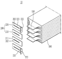
도 1은 본 발명의 일 실시예에 따른 전지 모듈의 일부를 확대 도시한 도면이다. 1 is an enlarged view showing a part of a battery module according to an embodiment of the present invention.
도 1을 참조하면, 본 발명의 일 실시예에 따른 전지 모듈(10)은, 전지 셀(100)이 복수 개 적층되어 있는 전지 셀 적층체 및 상기 복수의 전지 셀(100)들을 전기적으로 연결하는 버스바(200)를 포함한다.Referring to FIG. 1, a
상기 전지 셀 적층체를 구성하는 개개의 전지 셀(100)은 예를 들면 파우치 타입 전지 셀로서 전극 조립체를 파우치 케이스에 수용한 형태를 가질 수 있고, 이들은 서로 전기적으로 연결될 수 있다. 상기 전극 조립체는 양극판, 음극판 및 세퍼레이터를 포함하여 구성될 수 있으며, 공지의 구조를 갖는 전극 조립체를 채택할 수 있으므로 여기에서는 자세한 설명을 생략한다.The
전극 조립체에 연결된 한 쌍의 전극 리드(110)는 파우치 케이스의 외측으로 인출되고, 예를 들면 서로 동일한 방향 또는 반대 방향으로 인출될 수 있다. 본 발명의 도면에서는 도면 도시의 편의상 한 쌍의 전극 리드(110)가 서로 반대방향으로 인출된 형태를 갖는 파우치 타입 전지 셀(100)에 대해서만 도시하고 있으나, 본 발명에 따른 전지 모듈에 적용되는 전지 셀(100)은 반드시 이에 한정되는 것은 아니며, 한 쌍의 전극 리드(110)가 서로 동일한 방향으로 인출되는 경우도 가능하다.The pair of electrode leads 110 connected to the electrode assembly is drawn out of the pouch case, and may be drawn out in the same or opposite directions to each other, for example. In the drawing of the present invention, for convenience of the drawing, only a pair of
상기 전지 셀(100)들은 서로 동일한 극성을 갖는 전극 리드(11)들이 동일한 방향에 위치하도록 적층된다. 이는 버스바(200)를 이용하여 전극 리드(110)들을 전기적으로 연결시키는 경우 동일한 극성을 갖는 전극 리드(110)들끼리 연결이 되어야 하기 때문이다. 이처럼 동일한 극성을 갖는 전극 리드(110)들끼리 전기적으로 연결이 됨으로써 각각의 전지 셀(100)들은 병렬 연결을 이루게 된다.The
상기 전극 리드(110)로는, 예를 들면 니켈(Ni)이 코팅된 알루미늄(Al) 재질의 얇은 금속 플레이트가 이용될 수 있고, 이러한 전극 리드(110)와 버스바(200)의 결합을 위한 용접 작업이 원활하게 이루어지도록 하기 위해 전극 리드(110)의 표면에 주석(Sn) 코팅을 해 둘 수 있다.As the
버스바(200)는 각각의 전지 셀(100)에 구비된 전극 리드(110)들을 전기적으로 연결시키기 위한 것으로서, 전극 리드(110)들이 삽입될 수 있는 슬릿(202)을 포함할 수 있다. 슬릿(202)에 삽입된 전극 리드(110)를 절곡하여 전극 리드(110)와 버스바(200)가 면접촉하도록 한 후 용접 등에 의해 연결하는 것에 의해 전기적 연결을 달성할 수 있다.The
버스바(200)는 전지 모듈(10) 내의 전지 셀(100)들을 병렬 연결하는데 사용되는 제1 버스바(210)와, 전지 모듈(10)을 외부의 단자와 전기적으로 연결하는데 사용되는 제2 버스바(220)를 포함할 수 있다. 제 1 버스바(210)는 도 1에 도시된 바와 같이 평판형의 버스바 본체(211)와 이에 형성된 슬릿(202)을 포함할 수 있으나, 그 구조가 이에 한정되는 것은 아니다. 즉, 하나의 본체에 복수의 슬릿을 포함하는 형태나, 전극 리드 외의 다른 부품과의 결합을 위한 추가의 홀 또는 돌기 등을 포함할 수도 있으며, 필요에 따라 적절히 변형할 수 있다. 제2 버스바(220)는 도 1에 도시한 바와 같이, 슬릿(202)을 포함하는 버스바 본체(221)와, 상기 버스바 본체(221)의 일단으로부터 연장되어 전지 모듈(100)과 반대 방향을 향해 버스바 본체(221)와 대략 수직이 되도록 절곡되어 형성된 단자 연결부(222)를 포함할 수 있다. 단자 연결부(222)는 외부의 단자와 연결될 수 있는 하나 이상의 홀(223)을 포함할 수 있다.The
이러한 버스바(200)는 버스파 프레임(도시하지 않음) 등에 결합되어 전지 셀 적층체를 수용하는 모듈 프레임(도시하지 않음)과 버스바 프레임이 결합하는 것에 의해 전극 리드(110)와 결합할 수 있으나, 특별히 한정되는 것은 아니다.The
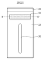
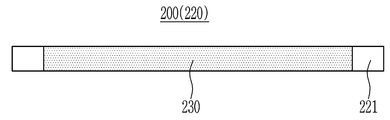
도 2는 도 1에 나타낸 전지 모듈의 버스바를 도시한 정면도이고, 도 3은 도 2에 나타낸 버스바의 III-III'에 따른 단면을 도시한 도면이다.FIG. 2 is a front view showing a bus bar of the battery module shown in FIG. 1, and FIG. 3 is a view showing a cross section along III-III' of the bus bar shown in FIG. 2.
도 1, 도 2 및 도 3을 참조하면, 버스바(200, 본 실시예에서는 제2 버스바(220)를 예로 들어 설명한다)는 버스바 본체(221)의 일부에 삽입되어 버스바 본체(221)에 의해 둘러싸여 있는 안전부(230)를 포함한다.1, 2 and 3, the bus bar 200 (in this embodiment, the
안전부(230)는 부피 팽창 수지, 전도성 물질 및 접착제를 포함하여 이루어진다. 즉, 부피 팽창 수지, 전도성 물질 및 접착제가 혼합되어 있는 페이스트 상태의 물질을, 버스바 본체(221)에 형성된 공간(홀)에 채운 후 경화시키는 것에 의해 안전부(230)가 형성될 수 있으며, 이 때문에 안전부(230)는 버스바 본체(221)와 동일한 두께를 가질 수 있다.The
안전부(230)에 포함된 부피 팽창 수지는 소정 온도 이상의 환경, 구체적으로는 110℃ 내지 120℃ 이상의 환경에서 가스를 발생시키는 물질을 포함한다. 즉, 부피 팽창 수지는 110℃ 내지 120℃ 이상의 온도에서 열분해되어 가스를 발생시킬 수 있는 물질이다. 이러한 부피 팽창 수지의 예로는 멜라민 시아누레이트(melamine cyanurate) 등을 들 수 있다.The volume expansion resin included in the
안전부(230)에 포함된 전도성 물질은 도전성의 분말일 수 있고, 예를 들면 금속 분말 또는 탄소 분말을 사용할 수 있다. 금속 분말의 예로는 은, 알루미늄, 금, 납 등을 들 수 있으나, 특별히 한정되는 것은 아니다. 이러한 도선성의 분말을 접착제와 혼합하여 사용하거나 또는, 시판의 메탈 페이스트(metal paste)를 상기 부피 팽창 수지와 후술의 접착제와 함께 혼합하여 안전부(230)를 형성할 수 있다. 안전부(230)는 이러한 전도성 물질을 포함하기 때문에, 전지 모듈이 정상적으로 작동할 때(즉, 비정상적인 온도 상승이 발생하지 않을 때) 안전부(230)에 의한 버스바(200)의 저항 증가가 발생함이 없이 원활하게 전류를 전달할 수 있도록 한다.The conductive material included in the
안전부(230)에 포함된 접착제는, 부피 팽창 수지 및 전도성 물질과 혼합되어 페이스트 형태를 만들고 경화될 수 있는 수지라면 특별히 한정되지 않고, 예를 들면 에폭시 수지 등을 사용할 수 있다. The adhesive included in the
부피 팽창 수지, 전도성 물질, 및 접착제를 혼합하여 페이스트 형태로 만든 후 이를 버스바 본체(221)에 형성된 공간(홀)에 채운 후 경화시키는 것에 의해 안전부(230)를 형성할 수 있다. 안전부(230)에 포함된 부피 팽창 수지는, 전지 모듈 내의 온도가 비정상적으로 상승(열폭주)하여 110℃ 내지 120℃ 이상이 될 경우 열분해되어 가스를 발생시킨다. 예를 들면 부피 팽창 수지로서 멜라민 이소시아누레이트를 사용할 경우 열분해에 의해 질소 기체가 발생한다. 이와 같이 가스가 발생하면 안전부(230)가 팽창하여 저항이 증가하게 된다. 즉, 안전부(230)가 저항층으로 작용하게 되어 안전부(230)를 중심으로 양 측 사이에 저항이 증가하기 때문에 전류가 흐르지 않거나, 흐르는 전류의 양이 감소하게 된다. 따라서 비정상적인 작동에 의해 급격한 온도 상승이 발생하는 경우 효율적으로 전류를 차단하여 전지 모듈의 안전성을 향상시킬 수 있다.The
또한, 도 3에 나타난 바와 같이 부피 팽창 수지, 전도성 물질, 및 접착제를 혼합하여 안전부(230)를 형성하는 경우, 버스바 본체(221)와 동일한 두께로 안전부(230)를 형성할 수 있고, 따라서 안전부(230)를 부가하더라도 종래의 버스바(200)의 구조 자체의 변경이 발생하지 않기 때문에 설계 변경 없이 용이하게 안전부(230)의 구성을 채용할 수 있다.In addition, as shown in FIG. 3, when the
도 2에서는 제2 버스바(220)에 포함된 안전부(230)를 예로 들어 설명하였으나, 안전부(230)는 제1 버스바(210)에 포함될 수도 있고, 또한 전기적 연결을 위해 채용된 다른 부품의 안전성을 위해서도 채용될 수 있으며, 특별히 한정되는 것은 아니다. 다만, 외부의 단자와 연결되는 단자 연결부(222) 근방에 안전부(230)가 위치할 경우, 외부와의 전류 흐름이 차단되기 때문에 전지 모듈(10) 전체에 대해 보다 빠르고 효과적으로 전류 차단의 효과를 달성할 수 있다는 점에서 이점이 있다. 즉, 도 2에 도시된 바와 같이 안전부(230)는 슬릿(202)과 단자 연결부(222) 사이에 위치할 수 있고, 이에 의해 보다 적은 양 및 작은 면적의 안전부(230)에 의하더라도 전지 모듈(10) 전체에 대해 외부로부터의 전기적 연결을 신속하게 차단할 수 있다.In FIG. 2, the
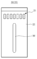
도 4는 본 발명의 다른 일 실시예에 따른 버스바를 도시한 정면도이다.4 is a front view showing a bus bar according to another embodiment of the present invention.
도 4를 참조하면, 본 발명의 다른 실시예에 따른 버스바(200)는 복수의 스트라이프가 집합된 형태로 형성된 안전부(231)를 포함할 수 있다. 안전부(231)의 형태를 제외한 다른 구성은 앞선 실시예와 동일한바, 여기서는 그 설명을 생략한다.Referring to FIG. 4, the
본 실시예의 버스바(200)에 포함된 안전부(231)는 복수의 스트라이프가 집합된 형태로서, 버스바 본체(221)에 패턴 형상의 구멍을 복수로 형성한 후 이를 앞서 설명한 부피 팽창 수지, 전도성 물질 및 접착제를 혼합하여 얻어진 페이스트로 채워서 경화하는 것에 의해 형성될 수 있다. 이에 의하면, 페이스트에 의해 채워지는 각 영역이 좁기 때문에, 페이스트의 점도가 다소 묽더라도 이에 영향받지 않고 안전부(231)를 형성할 수 있게 되어 가공성이 향상된다.The
또한 이러한 형상에 의하더라도, 비정상적으로 온도가 상승할 경우 안전부(231)가 형성된 영역에서 부피 팽창 수지에 의한 열분해가 충분히 일어나기 때문에 안전부(231)에 의한 전류 차단 효과는 동일하게 달성될 수 있다.In addition, even with this shape, when the temperature rises abnormally, since the thermal decomposition by the volume expansion resin sufficiently occurs in the region where the
한편, 본 발명의 실시예에 따른 전지 모듈은 하나 또는 그 이상이 팩 케이스 내에 패키징되어 전지 팩을 형성할 수 있다.On the other hand, the battery module according to an embodiment of the present invention may be packaged in one or more of the pack case to form a battery pack.
앞에서 설명한 전지 모듈 및 이를 포함하는 전지 팩은 다양한 디바이스에 적용될 수 있다. 이러한 디바이스에는, 전기 자전거, 전기 자동차, 하이브리드 자동차 등의 운송 수단에 적용될 수 있으나, 본 발명은 이에 제한되지 않고 전지 모듈 및 이를 포함하는 전지 팩을 사용할 수 있는 다양한 디바이스에 적용 가능하며, 이 또한 본 발명의 권리범위에 속한다.The battery module described above and the battery pack including the same can be applied to various devices. Such a device may be applied to a transportation means such as an electric bicycle, an electric vehicle, a hybrid vehicle, etc., but the present invention is not limited thereto, and is applicable to various devices that can use a battery module and a battery pack including the same, and this invention It belongs to the scope of the invention.
이상에서 본 발명의 바람직한 실시예에 대하여 상세하게 설명하였지만 본 발명의 권리범위는 이에 한정되는 것은 아니고 다음의 청구범위에서 정의하고 있는 본 발명의 기본 개념을 이용한 당업자의 여러 변형 및 개량 형태 또한 본 발명의 권리범위에 속하는 것이다.The preferred embodiments of the present invention have been described in detail above, but the scope of the present invention is not limited to this, and various modifications and improvements of those skilled in the art using the basic concepts of the present invention defined in the following claims are also provided. It belongs to the scope of rights.
10: 전지 모듈
100: 전지 셀
110: 전극 리드
200: 버스바
210: 제1 버스바
220: 제2 버스바
230, 231: 안전부
202: 슬릿
211, 221: 버스바 본체
222: 단자 연결부
223: 홀10: battery module 100: battery cell
110: electrode lead 200: bus bar
210: first bus bar 220: second bus bar
230, 231: safety section 202: slit
211, 221: bus bar body 222: terminal connection
223: Hall
Claims (13)
상기 복수의 전지 셀을 전기적으로 연결하는 버스바를 포함하고,
상기 버스바는 버스바 본체, 및 상기 버스바 본체의 일부에 삽입되어 버스바 본체에 의해 둘러싸여 있는 안전부를 포함하고,
상기 안전부는 부피 팽창 수지, 전도성 물질 및 접착제를 포함하는 전지 모듈.A plurality of battery cells, and
It includes a bus bar for electrically connecting the plurality of battery cells,
The bus bar includes a bus bar body and a safety part inserted into a part of the bus bar body and surrounded by the bus bar body,
The safety unit is a battery module comprising a bulk expansion resin, a conductive material and an adhesive.
상기 안전부는 상기 버스바 본체와 동일한 두께를 갖는 전지 모듈.In claim 1,
The safety unit is a battery module having the same thickness as the body of the busbar.
상기 부피 팽창 수지는 소정 온도 이상의 환경에서 가스를 발생시키는 물질을 포함하는 전지 모듈.In claim 1,
The volume expansion resin is a battery module comprising a material that generates a gas in an environment of a predetermined temperature or more.
상기 부피 팽창 수지는 멜라민 시아누레이트(melamine cyanurate)를 포함하는 전지 모듈.In claim 1,
The volume expansion resin is a battery module comprising melamine cyanurate (melamine cyanurate).
상기 안전부는 상기 부피 팽창 수지, 상기 전도성 물질, 및 상기 접착제가 혼합되어 형성되는 전지 모듈.In claim 1,
The safety unit is a battery module formed by mixing the volume expansion resin, the conductive material, and the adhesive.
상기 소정 온도 이상의 환경에서 부피 팽창 수지에서 가스가 발생하는 것에 의해 상기 안전부의 저항이 상승하여 전류가 차단되는 전지 모듈.In claim 3,
A battery module in which the resistance of the safety part rises and the current is cut off by generating gas in a volume expansion resin in an environment above the predetermined temperature.
상기 소정 온도 미만의 환경에서 상기 안전부는 상기 전도성 물질에 의해 도전성을 갖는 전지 모듈.In claim 3,
In an environment below the predetermined temperature, the safety unit is a battery module having conductivity by the conductive material.
상기 전도성 물질은 금속 분말 또는 탄소 분말인 전지 모듈.In claim 7,
The conductive material is a metal powder or carbon powder battery module.
상기 소정 온도는 110℃ 내지 120℃인 전지 모듈.In claim 3,
The predetermined temperature is 110 ℃ to 120 ℃ battery module.
상기 버스바는, 상기 버스바 본체에 형성되고, 상기 복수의 전지 셀로부터 연장된 리드가 삽입되는 슬릿, 및 상기 버스바 본체의 일단부로부터 연장되어 절곡된 형상을 갖는 단자 연결부를 포함하고, 상기 안전부는 상기 슬릿과 상기 단자 연결부 사이에 위치하는 전지 모듈.In claim 1,
The bus bar includes a slit formed in the bus bar body, into which leads extending from the plurality of battery cells are inserted, and a terminal connection part extending from one end of the bus bar body and having a bent shape. The safety part is a battery module located between the slit and the terminal connection part.
상기 안전부는 복수의 스트라이프가 집합된 형상을 갖는 전지 모듈.In claim 1,
The safety unit is a battery module having a shape in which a plurality of stripes are collected.
상기 적어도 하나의 전지 모듈을 패키징하는 팩 케이스
를 포함하는 전지 팩.At least one battery module according to any one of claims 1 to 11, and
Pack case for packaging the at least one battery module
Battery pack comprising a.
Priority Applications (6)
| Application Number | Priority Date | Filing Date | Title |
|---|---|---|---|
| KR1020180161298A KR20200073042A (en) | 2018-12-13 | 2018-12-13 | Battery module |
| JP2021531029A JP7246484B2 (en) | 2018-12-13 | 2019-10-07 | battery module |
| EP19896335.7A EP3876306A4 (en) | 2019-10-07 | Battery module | |
| US17/296,380 US20220037744A1 (en) | 2018-12-13 | 2019-10-07 | Battery module |
| PCT/KR2019/013121 WO2020122386A1 (en) | 2018-12-13 | 2019-10-07 | Battery module |
| CN201980077748.2A CN113632309B (en) | 2018-12-13 | 2019-10-07 | Battery module, battery pack including the same, and device including the battery pack |
Applications Claiming Priority (1)
| Application Number | Priority Date | Filing Date | Title |
|---|---|---|---|
| KR1020180161298A KR20200073042A (en) | 2018-12-13 | 2018-12-13 | Battery module |
Publications (1)
| Publication Number | Publication Date |
|---|---|
| KR20200073042A true KR20200073042A (en) | 2020-06-23 |
Family
ID=71076108
Family Applications (1)
| Application Number | Title | Priority Date | Filing Date |
|---|---|---|---|
| KR1020180161298A KR20200073042A (en) | 2018-12-13 | 2018-12-13 | Battery module |
Country Status (5)
| Country | Link |
|---|---|
| US (1) | US20220037744A1 (en) |
| JP (1) | JP7246484B2 (en) |
| KR (1) | KR20200073042A (en) |
| CN (1) | CN113632309B (en) |
| WO (1) | WO2020122386A1 (en) |
Cited By (1)
| Publication number | Priority date | Publication date | Assignee | Title |
|---|---|---|---|---|
| KR20220120514A (en) | 2021-02-22 | 2022-08-30 | (주)에이유플렉스 | Metal Plate Structure for Protecting Bottom of Flexible Display Panel |
Families Citing this family (2)
| Publication number | Priority date | Publication date | Assignee | Title |
|---|---|---|---|---|
| KR20200073042A (en) * | 2018-12-13 | 2020-06-23 | 주식회사 엘지화학 | Battery module |
| CN113871801B (en) * | 2020-06-30 | 2023-03-14 | 比亚迪股份有限公司 | Battery module, battery and battery package |
Family Cites Families (27)
| Publication number | Priority date | Publication date | Assignee | Title |
|---|---|---|---|---|
| US5406245A (en) * | 1993-08-23 | 1995-04-11 | Eaton Corporation | Arc-quenching compositions for high voltage current limiting fuses and circuit interrupters |
| JP2000149744A (en) * | 1998-11-16 | 2000-05-30 | Yazaki Corp | Circuit breaking device |
| KR20050058521A (en) * | 2002-08-30 | 2005-06-16 | 타이코 일렉트로닉스 레이켐 케이. 케이. | Conduction terminal and adapter for conduction terminal |
| JP2004211026A (en) * | 2003-01-08 | 2004-07-29 | Sumitomo Rubber Ind Ltd | Flame retardant seamless belt, method for producing the same and image-forming device equipped with the same |
| KR100561308B1 (en) * | 2004-05-31 | 2006-03-15 | 삼성에스디아이 주식회사 | Secondary Battery |
| CN101031614B (en) * | 2004-10-28 | 2011-07-27 | 陶氏康宁公司 | Conductive curable compositions |
| JP4829587B2 (en) * | 2005-10-14 | 2011-12-07 | 日本電気株式会社 | Electrical device assembly and manufacturing method thereof |
| JP4908042B2 (en) * | 2006-04-06 | 2012-04-04 | 三菱電機株式会社 | Circuit breaker |
| US8815429B2 (en) * | 2009-01-12 | 2014-08-26 | A123 Systems Llc | Busbar supports and methods of their use for battery systems |
| JP2013014734A (en) * | 2011-07-06 | 2013-01-24 | Nitto Denko Corp | Conductive pressure-sensitive adhesive tape |
| KR101595607B1 (en) * | 2011-12-07 | 2016-02-18 | 주식회사 엘지화학 | Secondary battery with improved safety |
| JP2014519153A (en) * | 2012-01-03 | 2014-08-07 | エルジー・ケム・リミテッド | Battery pack and connecting bar applied to it |
| KR101614434B1 (en) * | 2012-08-31 | 2016-05-02 | 주식회사 엘지화학 | Battery cell with improved safety |
| KR20140125704A (en) * | 2013-04-19 | 2014-10-29 | 주식회사 엘지화학 | Connecting component with insulating layer for a secondary battery, and Secondary battery module and pack comprising the same |
| KR20150062694A (en) * | 2013-11-29 | 2015-06-08 | 주식회사 엘지화학 | Element for secondary battery and Secondary battery comprising the same |
| KR20150099193A (en) * | 2014-02-21 | 2015-08-31 | 삼성에스디아이 주식회사 | Rechargeable battery module |
| KR20150121519A (en) * | 2014-04-21 | 2015-10-29 | 에스케이배터리시스템즈 주식회사 | Battery Module and Battery Pack having welding structure for guarantee at safety for short circuit |
| JP6724785B2 (en) * | 2014-10-27 | 2020-07-15 | 日本電気株式会社 | Secondary battery, electric vehicle, power storage system, and manufacturing method |
| KR102381777B1 (en) * | 2015-02-25 | 2022-04-01 | 삼성에스디아이 주식회사 | Battery pack |
| JP2017109548A (en) * | 2015-12-15 | 2017-06-22 | 株式会社東海理化電機製作所 | Direction indicator mechanism and method for assembling the same |
| CN107369835B (en) * | 2016-05-12 | 2020-12-25 | 华为技术有限公司 | Conductive adhesive for lithium ion battery and preparation method thereof, lithium ion battery electrode plate and preparation method thereof, and lithium ion battery |
| KR102085343B1 (en) * | 2016-12-05 | 2020-03-05 | 주식회사 엘지화학 | Cylindrical secondary battery module |
| KR102234223B1 (en) * | 2017-02-16 | 2021-03-31 | 주식회사 엘지화학 | Secondary Battery with improved Stability having Heat Expandable Tape and Method thereof |
| EP3588623A4 (en) * | 2017-02-24 | 2020-12-23 | Zeon Corporation | Electrode for electrochemical element, and electrochemical element |
| KR102383415B1 (en) * | 2018-03-20 | 2022-04-06 | 삼성에스디아이 주식회사 | Battery pack |
| KR102450418B1 (en) * | 2018-12-07 | 2022-09-30 | 주식회사 엘지에너지솔루션 | Battery module with improved safety, battery pack comprising the battery module and vehicle comprising the same |
| KR20200073042A (en) * | 2018-12-13 | 2020-06-23 | 주식회사 엘지화학 | Battery module |
-
2018
- 2018-12-13 KR KR1020180161298A patent/KR20200073042A/en not_active Application Discontinuation
-
2019
- 2019-10-07 WO PCT/KR2019/013121 patent/WO2020122386A1/en unknown
- 2019-10-07 CN CN201980077748.2A patent/CN113632309B/en active Active
- 2019-10-07 US US17/296,380 patent/US20220037744A1/en active Pending
- 2019-10-07 JP JP2021531029A patent/JP7246484B2/en active Active
Cited By (1)
| Publication number | Priority date | Publication date | Assignee | Title |
|---|---|---|---|---|
| KR20220120514A (en) | 2021-02-22 | 2022-08-30 | (주)에이유플렉스 | Metal Plate Structure for Protecting Bottom of Flexible Display Panel |
Also Published As
| Publication number | Publication date |
|---|---|
| CN113632309B (en) | 2023-10-24 |
| EP3876306A1 (en) | 2021-09-08 |
| JP2022513680A (en) | 2022-02-09 |
| WO2020122386A1 (en) | 2020-06-18 |
| CN113632309A (en) | 2021-11-09 |
| JP7246484B2 (en) | 2023-03-27 |
| US20220037744A1 (en) | 2022-02-03 |
Similar Documents
| Publication | Publication Date | Title |
|---|---|---|
| US10862082B2 (en) | Battery module assembly | |
| US9673495B2 (en) | Battery module assembly having coolant flow channel | |
| CN110710051B (en) | Battery pack | |
| EP3349269B1 (en) | Battery module, and battery pack and vehicle comprising the same | |
| CN108463901B (en) | Battery module and battery pack including the same | |
| EP3836247A1 (en) | Battery module, battery pack comprising such battery module, and vehicle comprising such battery pack | |
| JP7246484B2 (en) | battery module | |
| CN107408651B (en) | Battery module, battery pack including the same, and method of manufacturing case for battery module | |
| JP2019536238A (en) | battery pack | |
| EP4181275A1 (en) | Battery module and battery pack including same | |
| CN109845024B (en) | Battery system and electric vehicle including the same | |
| KR20150062688A (en) | Battery cell, Battery module and battery pack comprising the same | |
| US11721839B2 (en) | Electrode assembly with improved connection between electrode tabs | |
| CN116195115A (en) | Battery module and battery pack including the same | |
| EP3514004B1 (en) | Battery module and battery pack including same | |
| CN115088121A (en) | Battery module and battery pack including the same | |
| US20210242525A1 (en) | Battery Module Comprising Module Housing | |
| KR102633457B1 (en) | Battery module assembly | |
| EP4131579A1 (en) | Battery module and battery pack comprising same | |
| EP4131580A1 (en) | Battery module and battery pack including same | |
| KR20190007744A (en) | Battery module and battery pack including the same | |
| KR20220047057A (en) | Battery module and battery pack including the same and vehicle including the same | |
| CN117413421A (en) | Battery module, battery pack including the same, and vehicle | |
| KR20220075045A (en) | Battery module and battery pack including the same and vehicle including the same |
Legal Events
| Date | Code | Title | Description |
|---|---|---|---|
| E902 | Notification of reason for refusal |