EP4131580A1 - Battery module and battery pack including same - Google Patents
Battery module and battery pack including same Download PDFInfo
- Publication number
- EP4131580A1 EP4131580A1 EP22759981.8A EP22759981A EP4131580A1 EP 4131580 A1 EP4131580 A1 EP 4131580A1 EP 22759981 A EP22759981 A EP 22759981A EP 4131580 A1 EP4131580 A1 EP 4131580A1
- Authority
- EP
- European Patent Office
- Prior art keywords
- busbar
- battery
- heat transfer
- transfer member
- battery module
- Prior art date
- Legal status (The legal status is an assumption and is not a legal conclusion. Google has not performed a legal analysis and makes no representation as to the accuracy of the status listed.)
- Pending
Links
- 238000001816 cooling Methods 0.000 claims description 25
- 239000011347 resin Substances 0.000 claims description 22
- 229920005989 resin Polymers 0.000 claims description 22
- 239000000463 material Substances 0.000 claims description 4
- 230000020169 heat generation Effects 0.000 description 7
- 238000005520 cutting process Methods 0.000 description 6
- 239000000853 adhesive Substances 0.000 description 3
- 230000001070 adhesive effect Effects 0.000 description 3
- 230000000694 effects Effects 0.000 description 3
- 238000000034 method Methods 0.000 description 3
- 238000007789 sealing Methods 0.000 description 3
- 230000000052 comparative effect Effects 0.000 description 2
- 230000017525 heat dissipation Effects 0.000 description 2
- 238000003466 welding Methods 0.000 description 2
- 239000004677 Nylon Substances 0.000 description 1
- 239000011149 active material Substances 0.000 description 1
- 230000000712 assembly Effects 0.000 description 1
- 238000000429 assembly Methods 0.000 description 1
- 238000006243 chemical reaction Methods 0.000 description 1
- 238000010292 electrical insulation Methods 0.000 description 1
- 238000003487 electrochemical reaction Methods 0.000 description 1
- 239000008151 electrolyte solution Substances 0.000 description 1
- 238000004146 energy storage Methods 0.000 description 1
- 238000005516 engineering process Methods 0.000 description 1
- 239000010408 film Substances 0.000 description 1
- 230000004927 fusion Effects 0.000 description 1
- 230000005484 gravity Effects 0.000 description 1
- 238000009413 insulation Methods 0.000 description 1
- 230000010354 integration Effects 0.000 description 1
- 238000005304 joining Methods 0.000 description 1
- 239000007788 liquid Substances 0.000 description 1
- 239000007769 metal material Substances 0.000 description 1
- 238000012986 modification Methods 0.000 description 1
- 230000004048 modification Effects 0.000 description 1
- 229920001778 nylon Polymers 0.000 description 1
- 230000001151 other effect Effects 0.000 description 1
- 239000000243 solution Substances 0.000 description 1
- 239000000126 substance Substances 0.000 description 1
- 239000010409 thin film Substances 0.000 description 1
Images


Classifications
-
- H—ELECTRICITY
- H01—ELECTRIC ELEMENTS
- H01M—PROCESSES OR MEANS, e.g. BATTERIES, FOR THE DIRECT CONVERSION OF CHEMICAL ENERGY INTO ELECTRICAL ENERGY
- H01M10/00—Secondary cells; Manufacture thereof
- H01M10/60—Heating or cooling; Temperature control
- H01M10/65—Means for temperature control structurally associated with the cells
- H01M10/653—Means for temperature control structurally associated with the cells characterised by electrically insulating or thermally conductive materials
-
- H—ELECTRICITY
- H01—ELECTRIC ELEMENTS
- H01M—PROCESSES OR MEANS, e.g. BATTERIES, FOR THE DIRECT CONVERSION OF CHEMICAL ENERGY INTO ELECTRICAL ENERGY
- H01M10/00—Secondary cells; Manufacture thereof
- H01M10/60—Heating or cooling; Temperature control
- H01M10/65—Means for temperature control structurally associated with the cells
- H01M10/655—Solid structures for heat exchange or heat conduction
- H01M10/6553—Terminals or leads
-
- H—ELECTRICITY
- H01—ELECTRIC ELEMENTS
- H01M—PROCESSES OR MEANS, e.g. BATTERIES, FOR THE DIRECT CONVERSION OF CHEMICAL ENERGY INTO ELECTRICAL ENERGY
- H01M10/00—Secondary cells; Manufacture thereof
- H01M10/60—Heating or cooling; Temperature control
- H01M10/64—Heating or cooling; Temperature control characterised by the shape of the cells
- H01M10/647—Prismatic or flat cells, e.g. pouch cells
-
- H—ELECTRICITY
- H01—ELECTRIC ELEMENTS
- H01M—PROCESSES OR MEANS, e.g. BATTERIES, FOR THE DIRECT CONVERSION OF CHEMICAL ENERGY INTO ELECTRICAL ENERGY
- H01M10/00—Secondary cells; Manufacture thereof
- H01M10/60—Heating or cooling; Temperature control
- H01M10/65—Means for temperature control structurally associated with the cells
- H01M10/655—Solid structures for heat exchange or heat conduction
- H01M10/6554—Rods or plates
-
- H—ELECTRICITY
- H01—ELECTRIC ELEMENTS
- H01M—PROCESSES OR MEANS, e.g. BATTERIES, FOR THE DIRECT CONVERSION OF CHEMICAL ENERGY INTO ELECTRICAL ENERGY
- H01M10/00—Secondary cells; Manufacture thereof
- H01M10/60—Heating or cooling; Temperature control
- H01M10/65—Means for temperature control structurally associated with the cells
- H01M10/658—Means for temperature control structurally associated with the cells by thermal insulation or shielding
-
- H—ELECTRICITY
- H01—ELECTRIC ELEMENTS
- H01M—PROCESSES OR MEANS, e.g. BATTERIES, FOR THE DIRECT CONVERSION OF CHEMICAL ENERGY INTO ELECTRICAL ENERGY
- H01M50/00—Constructional details or processes of manufacture of the non-active parts of electrochemical cells other than fuel cells, e.g. hybrid cells
- H01M50/20—Mountings; Secondary casings or frames; Racks, modules or packs; Suspension devices; Shock absorbers; Transport or carrying devices; Holders
- H01M50/204—Racks, modules or packs for multiple batteries or multiple cells
- H01M50/207—Racks, modules or packs for multiple batteries or multiple cells characterised by their shape
- H01M50/211—Racks, modules or packs for multiple batteries or multiple cells characterised by their shape adapted for pouch cells
-
- H—ELECTRICITY
- H01—ELECTRIC ELEMENTS
- H01M—PROCESSES OR MEANS, e.g. BATTERIES, FOR THE DIRECT CONVERSION OF CHEMICAL ENERGY INTO ELECTRICAL ENERGY
- H01M50/00—Constructional details or processes of manufacture of the non-active parts of electrochemical cells other than fuel cells, e.g. hybrid cells
- H01M50/20—Mountings; Secondary casings or frames; Racks, modules or packs; Suspension devices; Shock absorbers; Transport or carrying devices; Holders
- H01M50/233—Mountings; Secondary casings or frames; Racks, modules or packs; Suspension devices; Shock absorbers; Transport or carrying devices; Holders characterised by physical properties of casings or racks, e.g. dimensions
- H01M50/24—Mountings; Secondary casings or frames; Racks, modules or packs; Suspension devices; Shock absorbers; Transport or carrying devices; Holders characterised by physical properties of casings or racks, e.g. dimensions adapted for protecting batteries from their environment, e.g. from corrosion
-
- H—ELECTRICITY
- H01—ELECTRIC ELEMENTS
- H01M—PROCESSES OR MEANS, e.g. BATTERIES, FOR THE DIRECT CONVERSION OF CHEMICAL ENERGY INTO ELECTRICAL ENERGY
- H01M50/00—Constructional details or processes of manufacture of the non-active parts of electrochemical cells other than fuel cells, e.g. hybrid cells
- H01M50/20—Mountings; Secondary casings or frames; Racks, modules or packs; Suspension devices; Shock absorbers; Transport or carrying devices; Holders
- H01M50/289—Mountings; Secondary casings or frames; Racks, modules or packs; Suspension devices; Shock absorbers; Transport or carrying devices; Holders characterised by spacing elements or positioning means within frames, racks or packs
-
- H—ELECTRICITY
- H01—ELECTRIC ELEMENTS
- H01M—PROCESSES OR MEANS, e.g. BATTERIES, FOR THE DIRECT CONVERSION OF CHEMICAL ENERGY INTO ELECTRICAL ENERGY
- H01M50/00—Constructional details or processes of manufacture of the non-active parts of electrochemical cells other than fuel cells, e.g. hybrid cells
- H01M50/50—Current conducting connections for cells or batteries
- H01M50/502—Interconnectors for connecting terminals of adjacent batteries; Interconnectors for connecting cells outside a battery casing
- H01M50/503—Interconnectors for connecting terminals of adjacent batteries; Interconnectors for connecting cells outside a battery casing characterised by the shape of the interconnectors
-
- H—ELECTRICITY
- H01—ELECTRIC ELEMENTS
- H01M—PROCESSES OR MEANS, e.g. BATTERIES, FOR THE DIRECT CONVERSION OF CHEMICAL ENERGY INTO ELECTRICAL ENERGY
- H01M50/00—Constructional details or processes of manufacture of the non-active parts of electrochemical cells other than fuel cells, e.g. hybrid cells
- H01M50/50—Current conducting connections for cells or batteries
- H01M50/502—Interconnectors for connecting terminals of adjacent batteries; Interconnectors for connecting cells outside a battery casing
- H01M50/505—Interconnectors for connecting terminals of adjacent batteries; Interconnectors for connecting cells outside a battery casing comprising a single busbar
-
- H—ELECTRICITY
- H01—ELECTRIC ELEMENTS
- H01M—PROCESSES OR MEANS, e.g. BATTERIES, FOR THE DIRECT CONVERSION OF CHEMICAL ENERGY INTO ELECTRICAL ENERGY
- H01M50/00—Constructional details or processes of manufacture of the non-active parts of electrochemical cells other than fuel cells, e.g. hybrid cells
- H01M50/50—Current conducting connections for cells or batteries
- H01M50/502—Interconnectors for connecting terminals of adjacent batteries; Interconnectors for connecting cells outside a battery casing
- H01M50/507—Interconnectors for connecting terminals of adjacent batteries; Interconnectors for connecting cells outside a battery casing comprising an arrangement of two or more busbars within a container structure, e.g. busbar modules
-
- H—ELECTRICITY
- H01—ELECTRIC ELEMENTS
- H01M—PROCESSES OR MEANS, e.g. BATTERIES, FOR THE DIRECT CONVERSION OF CHEMICAL ENERGY INTO ELECTRICAL ENERGY
- H01M10/00—Secondary cells; Manufacture thereof
- H01M10/60—Heating or cooling; Temperature control
- H01M10/61—Types of temperature control
- H01M10/613—Cooling or keeping cold
-
- H—ELECTRICITY
- H01—ELECTRIC ELEMENTS
- H01M—PROCESSES OR MEANS, e.g. BATTERIES, FOR THE DIRECT CONVERSION OF CHEMICAL ENERGY INTO ELECTRICAL ENERGY
- H01M2220/00—Batteries for particular applications
- H01M2220/30—Batteries in portable systems, e.g. mobile phone, laptop
-
- Y—GENERAL TAGGING OF NEW TECHNOLOGICAL DEVELOPMENTS; GENERAL TAGGING OF CROSS-SECTIONAL TECHNOLOGIES SPANNING OVER SEVERAL SECTIONS OF THE IPC; TECHNICAL SUBJECTS COVERED BY FORMER USPC CROSS-REFERENCE ART COLLECTIONS [XRACs] AND DIGESTS
- Y02—TECHNOLOGIES OR APPLICATIONS FOR MITIGATION OR ADAPTATION AGAINST CLIMATE CHANGE
- Y02E—REDUCTION OF GREENHOUSE GAS [GHG] EMISSIONS, RELATED TO ENERGY GENERATION, TRANSMISSION OR DISTRIBUTION
- Y02E60/00—Enabling technologies; Technologies with a potential or indirect contribution to GHG emissions mitigation
- Y02E60/10—Energy storage using batteries
Definitions
- the present disclosure relates to a battery module and a battery pack including the same, and more particularly, to a battery module having a novel cooling structure and a battery pack including the same.
- a secondary battery has attracted considerable attention as an energy source for power-driven devices, such as an electric bicycle, an electric vehicle, and a hybrid electric vehicle, as well as an energy source for mobile devices, such as a mobile phone, a digital camera, a laptop computer and a wearable device.
- Small-sized mobile devices use one or several battery cells for each device, whereas middle or large-sized devices such as vehicles require high power and large capacity. Therefore, a middle or large-sized battery module having a plurality of battery cells electrically connected to one another is used.
- the middle or large-sized battery module is preferably manufactured so as to have as small a size and weight as possible, a prismatic battery, a pouch-shaped battery or the like, which can be stacked with high integration and has a small weight relative to capacity, is mainly used as a battery cell of the middle or large-sized battery module.
- a battery module has a structure in which a plurality of cell assemblies including a plurality of unit battery cells are connected in series in order to obtain high output.
- the battery cell includes positive electrode and negative electrode current collectors, a separator, an active material, an electrolyte solution, and the like, and thus can be repeatedly charged and discharged by an electrochemical reaction between components.
- a method of first configuring a battery module composed of at least one battery cell and then adding other components to at least one battery module to configure a battery pack is common.
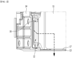
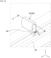
- Fig. 1 shows a perspective view according to a conventional battery module.
- Fig. 2 is an enlarged view showing a part of a cross-sectional view taken along the xz plane with reference to the cutting line A-A' of Fig. 1 .
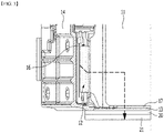
- Fig. 3 is a part of a cross-sectional view of a battery pack including a conventional battery module.
- the conventional battery module 10 includes a battery cell assembly consisting of a plurality of battery cells 11 stacked with each other, and a busbar assembly that electrically connects the electrode leads 12 of the plurality of battery cells 11 to each other, a module frame 13 that wraps the battery cell assembly, and an end plate 14 that covers a busbar assembly.
- the busbar assembly includes a busbar frame having lead slots that allow the discrete passage of the electrode leads 12 of each battery cell 11, and further includes a busbar 16 mounted on the busbar frame having busbar slots so as to correspond to the number of lead slots that allow the busbar 16 to be connected to the electrode leads passing through the busbar slots by welding, etc.
- the heat generated by a busbar 16 since the heat generated by a busbar 16 has no direct cooling path, it may be transmitted via the electrode lead 12, and then transferred via the battery cell 11, a thermal conductive resin layer 17 formed on the bottom part of the module frame 13, and the bottom part of the module frame 13.
- the transferred heat may be further transferred via the heat transfer member 20 and the cooling plate 21 formed inside the battery pack including the conventional battery module 10.
- a battery module comprising: a battery cell stack in which a plurality of battery cells are stacked, a module frame that wraps the battery cell stack, a busbar frame that covers a portion of the battery cell stack exposed from the module frame, a busbar that is connected to an electrode lead protruding from the battery cell stack via a slot formed in the busbar frame, an end plate that covers the busbar frame, and a heat transfer member that is connected to the busbar, wherein the heat transfer member comes into contact with the end plate.
- the busbar may be connected with the heat transfer member by bringing them into surface contact.
- the heat transfer member may be formed of a material having electrical insulating property and thermal conductivity.
- the battery module may further include an insulating cover located between the end plate and the busbar frame, wherein the insulating cover has a lid part that covers the heat transfer member except for a portion in which the heat transfer member comes into contact with the end plate and the busbar.
- the heat transfer member may be located to adjoin the lower end part of the end plate.
- the heat transfer members may be formed in plural numbers so as to be arranged apart from each other along the direction in which the plurality of battery cells are stacked.
- the heat transfer member may include a curved structure, and at least one surface may come into contact with the busbar via the curved structure.
- the heat transfer member may include a protruding bottom part that supports the lower end part of the busbar, and the protruding bottom part and the busbar may come into contact with each other.
- the end plate may come into contact with the module frame, and the heat generated from the busbar may be sequentially transferred to the heat transfer member, the end plate, and the bottom part of the module frame.
- a battery pack comprising: the above-mentioned battery module, a second thermal conductive resin layer located under the bottom part of the battery module, and a cooling plate located under the second thermal conductive resin layer.
- the problem of heat generation of the busbar in a high current and fast charging environment can be solved by a novel type of busbar cooling structure. Additionally, the stability of the battery module can be improved by solving the heat generation problem.
- planar when referred to as “planar”, it means when a target portion is viewed from the upper side, and when referred to as “cross-sectional”, it means when a target portion is viewed from the side of a cross section cut vertically.
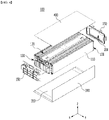
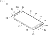
- Fig. 4 is an exploded perspective view of a battery module according to an embodiment of the present disclosure.
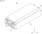
- Fig. 5 is a perspective view showing a state in which the components of the battery module of Fig. 4 are combined.
- Fig. 6 is a perspective view showing one battery cell included in the battery cell stack of Fig. 4 .
- the battery module 100 may include a battery cell stack 120 in which a plurality of battery cells 110 are stacked, a module frame that wraps the battery cell stack 120, an upper plate 400 that covers the upper part of the battery cell stack 120, end plates 150 that are respectively located on the front and rear surfaces of the battery cell stack 120, and a busbar frame 130 that is located between the battery cell stack 120 and the end plate 150.
- the busbar frame 130 may cover a portion of the battery cell stack 120 exposed from the module frame.
- the module frame may include a U-shaped frame 300 of which an upper surface, a front surface and a rear surface are opened.
- the battery module 100 includes a thermal conductive resin layer 310 located between the U-shaped frame 300 and the battery cell stack 120.
- the thermal conductive resin layer 310 is a kind of heat dissipation layer, and may be formed by applying a material having a heat dissipation function.
- the end plate 150 may be formed of a metal material.
- the U-shaped frame 300 When opened both sides of the U-shaped frame 300 are referred to as a first side and a second side, respectively, the U-shaped frame 300 has a plate-shaped structure that is bent so as to continuously warp the front, lower and rear surfaces adjacent to each other among the remaining outer surfaces excluding surfaces of the battery cell stack 120 corresponding to the first side and the second side.
- the upper surface corresponding to the lower surface of the U-shaped frame 300 is opened.
- the upper plate 400 has a single plate-shaped structure that covers the remaining upper surface excluding the front, lower and rear surfaces which are wrapped by the U-shaped frame 300.
- the U-shaped frame 300 and the upper plate 400 can be coupled by welding or the like in a state in which the corresponding edge areas are in contact with each other, thereby forming a structure wrapping the battery cell stack 120.
- the battery cell stack 120 includes a plurality of battery cells 110 stacked in one direction, and the plurality of battery cells 110 may be stacked in the y-axis direction as shown in Fig. 4 .
- a direction in which the plurality of battery cells 110 are stacked may be the same as a direction in which two side surface parts of the U-shaped frame 300 face each other.
- the battery cell 110 is preferably a pouch type battery cell.
- the battery cell 110 according to the present embodiment may have a structure in which the two electrode leads 111 and 112 protrude from one end part 114a and the other end part 114b of the battery main body 113 toward mutually opposite directions, respectively.
- the battery cell 110 can be manufactured by joining both end parts 114a and 114b of the cell case 114 and both side surfaces 114c connecting them in a state in which an electrode assembly (not shown) is housed in the cell case 114.
- the battery cell 110 has a total of three sealing parts 114sa, 114sb and 114sc, wherein the sealing parts 114sa, 114sb and 114sc have a structure that is sealed by a method such as heat fusion, and the remaining other side part may be formed of a connection part 115.
- Between both end parts 114a and 114b of the battery case 114 is defined as a longitudinal direction of the battery cell 110, and between the one side surface 114c and the connection part 115 that connect both end parts 114a and 114b of the battery case 114 is defined as a width direction of the battery cell 110.
- connection part 115 is a region that extends long along one edge of the battery cell 110, and a protrusion part 110p of the battery cell 110 may be formed at an end part of the connection part 115.
- the protrusion part 110p may be formed on at least one of both end parts of the connection part 115 and may protrude in a direction perpendicular to the direction in which the connection part 115 extends.
- the protrusion part 110p may be located between one of the sealing parts 114sa and 114sb of both end parts 114a and 114b of the battery case 114, and the connection part 115.
- the cell case 114 is generally formed of a laminated structure of a resin layer/metallic thin film layer/resin layer.
- a surface of the battery case formed of an O(oriented)-nylon layer tends to slide easily by an external impact when a plurality of battery cells are stacked in order to form a medium- or large-sized battery module. Therefore, in order to prevent this sliding and maintain a stable stacked structure of the battery cells, an adhesive member, for example, a sticky adhesive such as a double-sided tape or a chemical adhesive coupled by a chemical reaction upon adhesion, can be attached to the surface of the battery case to form the battery cell stack 120.
- a sticky adhesive such as a double-sided tape or a chemical adhesive coupled by a chemical reaction upon adhesion
- the battery cell stack 120 may be stacked in a y-axis direction and housed into the U-shaped frame 300 in a z-axis direction.
- the battery cells are formed as cartridge-shaped components so that fixing between the battery cells leads to assembling by the battery module frame.
- the cooling due to the presence of the cartridge-shaped components, there is almost no cooling action or the cooling may be proceeded in a surface direction of the battery cells, whereby the cooling does not well perform toward a height direction of the battery module.
- the U-shaped frame 300 includes a bottom part and two side surface parts facing each other connected by the bottom part.
- a thermal conductive resin is applied to the bottom part of the U-shaped frame 300, and the thermal conductive resin can be cured to form a thermal conductive resin layer 310.
- the thermal conductive resin layer 310 is located between the bottom part of the U-shaped frame 300 and the battery cell stack, and can serve to transfer heat generated in the battery cell 110 to the bottom of the battery module 100 and fix the battery cell stack 120.
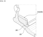
- Fig. 7 is a perspective view of an end plate included in the battery module of Fig. 4 .
- Fig. 8 is an enlarged view showing a section C of Fig. 7 .
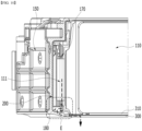
- Fig. 9 is an enlarged view showing a part of a cross-sectional view taken along the yz plane based on the cutting line D-D' of Fig. 8 .
- Fig. 10 is an enlarged view showing a part of a cross-sectional view taken along the xz plane with reference to the cutting line B-B' of Fig. 5 .
- Fig. 11 is an enlarged view showing a section E of Fig. 10 .
- the conventional battery module does not have a direct cooling path for the busbar, and thus, heat generated by the busbar was discharged only by a path connecting to the busbar, electrode leads, battery cells, thermal conductive resin layer and module frame bottom part.
- a cooling structure capable of minimizing the temperature rise of the busbar is needed.
- the battery module 100 includes a busbar 170 connected to the electrode lead 111 protruding from the battery cell stack 120 via the slot formed in the busbar frame 130, and a heat transfer member 180 connected to the busbar 170. At this time, the heat transfer member 180 comes into contact with the end plate 150.
- the busbar 170 may be connected with the heat transfer member 180 by bringing them into surface contact.
- the heat transfer member 180 includes a curved structure and at least one surface may come into contact with the busbar 170 via the curved structure.
- the heat transfer member 180 includes a protruding bottom part A that supports the lower end part of the busbar 170, and the protruding bottom part A and the busbar 170 may come into contact with each other.
- the curved structure may be formed to have the same shape as that of the busbar 170 so that the busbar 170 can be fitted into the structure, but is not limited thereto.
- a portion of the heat transfer member 180 can be configured without contacting with the busbar 170 so as not to apply mechanical stress to the busbar 170. Therefore, the heat generated in the busbar 170 may be transferred to the heat transfer member 180 by the contact, and cooling of the busbar 170 can be performed.
- the heat transfer member 180 may be formed of a material having electrical insulation properties and thermal conductivity.
- the heat transfer member 180 may include one of a heat transfer pad and a thermal conductive resin layer. Additionally, the heat transfer member 180 may be formed through a method in which the liquid is initially injected and then cured. The heat transfer member 180 has electric insulating property, but has thermal conductivity, thereby enabling heat conduction while maintaining the insulating property of the busbar 170.
- the heat generated from the busbar 170 may be sequentially transferred to the heat transfer member 180, the end plate 150, the bottom part of the module frame, particularly the U-shaped frame 300, and discharged.
- the heat transfer member 180 of the present disclosure may be located to adjoin the lower end part of the end plate 150. Specifically, the heat transfer member 180 may be located closer to the lower end part than the upper end part of the end plate 150.
- the heat transfer members 180 may be formed in plural numbers so as to be arranged apart from each other along the direction in which the plurality of battery cells 110 are stacked. Specifically, referring to Fig. 4 , the plurality of battery cells 110 may be stacked in the y-axis direction. Therefore, the heat transfer members 180 may be formed in plural numbers so as to be arranged apart from each other along the y-axis direction on the end plate 150.
- the heat transfer member 180 comes into contact with the end plate 150, thereby enabling rapid cooling. Further, the heat transfer member 180 of the present disclosure is located to adjoin the lower end part of the end plate 150, whereby when the temperature of the busbar 170 is high, it is possible to prevent the cooling performance of the heat transfer member 180 from being weakened due to the phase change of the heat transfer member 180.
- the heat transfer member 180 may be formed in consideration of the number of busbars 170 in contact with the heat transfer member 180, but is not limited thereto.
- the busbar 170 can be formed in a number that can maximize the cooling.
- a plurality of heat transfer members 180 may be formed so as to cover the entire lower end part of the end plate 150, or may be integrally formed so as to cover the whole of the lower end part of the end plate 150. Thereby, the heat transfer member 180 comes into contact with the end plate 180, so that the efficiency of possible rapid cooling can be further increased.
- the battery module according to an embodiment of the present disclosure may further include an insulating cover 200 that is located between the end plate 150 and the busbar frame 130.
- the insulating cover 200 includes a lid part 210 that covers the heat transfer member 180 except for a portion of the heat transfer member 180 in which the heat transfer member 180 comes into contact with the end plate 150 and the busbar 170.
- the insulating cover 200 may constitute the shape of the heat transfer member 180, and may serve to maintain the shape of the heat transfer member 180 so that the heat transfer member 180 is not detached or broken after assembling the module.
- the insulating property of the heat transfer member 180 can be secured through the lid part 210.
- the end plate 150 of the battery module may come into contact with the module frame.
- it can come into contact with the bottom part of the U-shaped frame 300, which is a module frame. Therefore, the heat generated in the busbar 170 can be transferred to the busbar 170, the heat transfer member 180, the end plate 150, and the bottom part of the module frame, particularly the U-shaped frame 300, and discharged.
- the U-shaped frame 300, the second thermal conductive resin layer 320 and the cooling plate 700 may be formed as a pack component, or the cooling plate 700 integrally formed with the battery module may be formed. Therefore, the heat transferred to the bottom part of the U-shaped frame 300 can be transferred to the second thermal conductive resin layer 320 and the cooling plate 700, and discharged. Therefore, the heat generated in the busbar 170 can be effectively cooled and discharged through the above transfer, and the stability of the battery module can be secured.
- Fig. 12 is a cross-sectional view showing a battery pack according to another embodiment of the present disclosure.
- the battery pack according to the present embodiment includes a second thermal conductive resin layer 320 located under the bottom part of the battery module, the U-shaped frame 300 described above, and a cooling plate 700 located under the second thermal conductive resin layer 320.
- the heat transferred to the busbar 170, the heat transfer member 180, the end plate 150, and the bottom part of the U-shaped frame 300 can be further transferred to the second thermal conductive resin layer 320 and the cooling plate 700.
- the heat generated in the busbar 170 is cooled through the path, thereby enabling effective cooling.
- the battery pack of the present disclosure may have a structure in which one or more of the battery modules according to the embodiment of the present disclosure are gathered, and packed together with a battery management system (BMS) and a cooling device that control and manage battery's temperature, voltage, etc.
- BMS battery management system
- the battery pack can be applied to various devices.
- a device may be applied to a vehicle means such as an electric bicycle, an electric vehicle, or a hybrid vehicle, but the present disclosure is not limited thereto, and is applicable to various devices that can use a battery module, which also falls under the scope of the present disclosure.
Abstract
Description
- This application claims the benefit of
Korean Patent Application No. 10-2021-0026972 filed on February 26, 2021 - The present disclosure relates to a battery module and a battery pack including the same, and more particularly, to a battery module having a novel cooling structure and a battery pack including the same.
- Along with the technology development and increased demand for mobile devices, demand for secondary batteries as energy sources has been increasing rapidly. In particular, a secondary battery has attracted considerable attention as an energy source for power-driven devices, such as an electric bicycle, an electric vehicle, and a hybrid electric vehicle, as well as an energy source for mobile devices, such as a mobile phone, a digital camera, a laptop computer and a wearable device.
- Small-sized mobile devices use one or several battery cells for each device, whereas middle or large-sized devices such as vehicles require high power and large capacity. Therefore, a middle or large-sized battery module having a plurality of battery cells electrically connected to one another is used.
- Since the middle or large-sized battery module is preferably manufactured so as to have as small a size and weight as possible, a prismatic battery, a pouch-shaped battery or the like, which can be stacked with high integration and has a small weight relative to capacity, is mainly used as a battery cell of the middle or large-sized battery module. Such a battery module has a structure in which a plurality of cell assemblies including a plurality of unit battery cells are connected in series in order to obtain high output. And, the battery cell includes positive electrode and negative electrode current collectors, a separator, an active material, an electrolyte solution, and the like, and thus can be repeatedly charged and discharged by an electrochemical reaction between components.
- Meanwhile, recently, along with a continuous rise of the necessity for a large-capacity secondary battery structure, including the utilization of the secondary battery as an energy storage source, there is a growing demand for a battery pack of a multi-module structure which is an assembly of battery modules in which a plurality of secondary batteries are connected in series or in parallel.
- Meanwhile, when a plurality of battery cells are connected in series or in parallel to configure a battery pack, a method of first configuring a battery module composed of at least one battery cell and then adding other components to at least one battery module to configure a battery pack is common.
-
Fig. 1 shows a perspective view according to a conventional battery module.Fig. 2 is an enlarged view showing a part of a cross-sectional view taken along the xz plane with reference to the cutting line A-A' ofFig. 1 .Fig. 3 is a part of a cross-sectional view of a battery pack including a conventional battery module. - Referring to
Figs. 1 and2 , theconventional battery module 10 includes a battery cell assembly consisting of a plurality ofbattery cells 11 stacked with each other, and a busbar assembly that electrically connects the electrode leads 12 of the plurality ofbattery cells 11 to each other, amodule frame 13 that wraps the battery cell assembly, and anend plate 14 that covers a busbar assembly. - Here, the busbar assembly includes a busbar frame having lead slots that allow the discrete passage of the electrode leads 12 of each
battery cell 11, and further includes abusbar 16 mounted on the busbar frame having busbar slots so as to correspond to the number of lead slots that allow thebusbar 16 to be connected to the electrode leads passing through the busbar slots by welding, etc. - At this time, since the heat generated by a
busbar 16 has no direct cooling path, it may be transmitted via theelectrode lead 12, and then transferred via thebattery cell 11, a thermalconductive resin layer 17 formed on the bottom part of themodule frame 13, and the bottom part of themodule frame 13. - In addition, referring to
Fig. 3 , the transferred heat may be further transferred via the heat transfer member 20 and thecooling plate 21 formed inside the battery pack including theconventional battery module 10. - Recently, there is a tendency to continuously increase the necessity for high capacity, high energy, fast charging, etc. and also increase the amount of current flowing through the busbar. The high current flowing through the busbar causes heat generation in the busbar, and such heat generation is difficult to effectively cool through the conventional cooling structure alone. Therefore, in order to cool the heat generation, there is a need for a structure that can make a direct contact with the busbar to cool the busbar.
- It is an object of the present disclosure to provide a battery module that can solve the heat generation problem of the busbar and a battery pack including the same.
- However, the objects of the present disclosure are not limited to the aforementioned objects, and other objects which are not described herein should be clearly understood by those skilled in the art from the following detailed description and the accompanying drawings.
- According to one aspect of the present disclosure, there is provided a battery module comprising: a battery cell stack in which a plurality of battery cells are stacked, a module frame that wraps the battery cell stack, a busbar frame that covers a portion of the battery cell stack exposed from the module frame, a busbar that is connected to an electrode lead protruding from the battery cell stack via a slot formed in the busbar frame, an end plate that covers the busbar frame, and a heat transfer member that is connected to the busbar, wherein the heat transfer member comes into contact with the end plate.
- The busbar may be connected with the heat transfer member by bringing them into surface contact.
- The heat transfer member may be formed of a material having electrical insulating property and thermal conductivity.
- The battery module may further include an insulating cover located between the end plate and the busbar frame, wherein the insulating cover has a lid part that covers the heat transfer member except for a portion in which the heat transfer member comes into contact with the end plate and the busbar.
- The heat transfer member may be located to adjoin the lower end part of the end plate.
- The heat transfer members may be formed in plural numbers so as to be arranged apart from each other along the direction in which the plurality of battery cells are stacked.
- The heat transfer member may include a curved structure, and at least one surface may come into contact with the busbar via the curved structure.
- The heat transfer member may include a protruding bottom part that supports the lower end part of the busbar, and the protruding bottom part and the busbar may come into contact with each other.
- The end plate may come into contact with the module frame, and the heat generated from the busbar may be sequentially transferred to the heat transfer member, the end plate, and the bottom part of the module frame.
- According to another aspect of the present disclosure, there is provided a battery pack comprising: the above-mentioned battery module, a second thermal conductive resin layer located under the bottom part of the battery module, and a cooling plate located under the second thermal conductive resin layer.
- According to embodiments of the present disclosure, the problem of heat generation of the busbar in a high current and fast charging environment can be solved by a novel type of busbar cooling structure. Additionally, the stability of the battery module can be improved by solving the heat generation problem.
- The effects of the present disclosure are not limited to the effects mentioned above and additional other effects not described above will be clearly understood from the description of the appended claims by those skilled in the art.
-
-
Fig. 1 shows a perspective view according to a conventional battery module; -
Fig. 2 is an enlarged view showing a part of a cross-sectional view taken along the xz plane with reference to the cutting line A-A' ofFig. 1 ; -
Fig. 3 is a part of a cross-sectional view of a battery pack including a conventional battery module; -
Fig. 4 is an exploded perspective view of a battery module according to an embodiment of the present disclosure; -
Fig. 5 is a perspective view showing a state in which the components of the battery module ofFig. 4 are combined; -
Fig. 6 is a perspective view showing one battery cell included in the battery cell stack ofFig. 4 ; -
Fig. 7 is a perspective view of an end plate included in the battery module ofFig. 4 ; -
Fig. 8 is an enlarged view showing a section C ofFig. 7 ; -
Fig. 9 is an enlarged view showing a part of a cross-sectional view taken along the yz plane based on the cutting line D-D' ofFig. 8 ; -
Fig. 10 is an enlarged view showing a part of a cross-sectional view taken along the xz plane with reference to the cutting line B-B' ofFig. 5 ; -
Fig. 11 is an enlarged view showing a section E ofFig. 10 ; and -
Fig. 12 is a cross-sectional view showing a battery pack according to another embodiment of the present disclosure. - Hereinafter, various embodiments of the present disclosure will be described in detail with reference to the accompanying drawings so that those skilled in the art can easily carry out them. The present disclosure can be modified in various different ways, and is not limited to the embodiments set forth herein.
- A description of parts not related to the description will be omitted herein for clarity, and like reference numerals designate like elements throughout the description.
- Further, in the drawings, the size and thickness of each element are arbitrarily illustrated for convenience of description, and the present disclosure is not necessarily limited to those illustrated in the drawings. In the drawings, the thickness of layers, regions, etc. are exaggerated for clarity. In the drawings, for convenience of description, the thicknesses of some layers and regions are exaggerated.
- In addition, it will be understood that when an element such as a layer, film, region, or plate is referred to as being "on" or "above" another element, it can be directly on the other element or intervening elements may also be present. In contrast, when an element is referred to as being "directly on" another element, it means that other intervening elements are not present. Further, the word "on" or "above" means disposed on or below a reference portion, and does not necessarily mean being disposed "on" or "above" the reference portion toward the opposite direction of gravity.
- Further, throughout the specification, when a portion is referred to as "including" or "comprising" a certain component, it means that the portion can further include other components, without excluding the other components, unless otherwise stated.
- Further, throughout the specification, when referred to as "planar", it means when a target portion is viewed from the upper side, and when referred to as "cross-sectional", it means when a target portion is viewed from the side of a cross section cut vertically.
- The terms "first," "second," etc. are used to explain various components, but the components should not be limited by the terms. These terms are only used to distinguish one component from the other component.
- Now, a battery module according to an embodiment of the present disclosure will be described with reference to
Figs. 4 to 11 . -
Fig. 4 is an exploded perspective view of a battery module according to an embodiment of the present disclosure.Fig. 5 is a perspective view showing a state in which the components of the battery module ofFig. 4 are combined.Fig. 6 is a perspective view showing one battery cell included in the battery cell stack ofFig. 4 . - Referring to
Figs. 4 and5 , thebattery module 100 according to an embodiment of the present disclosure may include abattery cell stack 120 in which a plurality ofbattery cells 110 are stacked, a module frame that wraps thebattery cell stack 120, anupper plate 400 that covers the upper part of thebattery cell stack 120,end plates 150 that are respectively located on the front and rear surfaces of thebattery cell stack 120, and abusbar frame 130 that is located between thebattery cell stack 120 and theend plate 150. Thebusbar frame 130 may cover a portion of thebattery cell stack 120 exposed from the module frame. At this time, the module frame may include aU-shaped frame 300 of which an upper surface, a front surface and a rear surface are opened. Further, thebattery module 100 includes a thermalconductive resin layer 310 located between theU-shaped frame 300 and thebattery cell stack 120. The thermalconductive resin layer 310 is a kind of heat dissipation layer, and may be formed by applying a material having a heat dissipation function. Theend plate 150 may be formed of a metal material. - When opened both sides of the
U-shaped frame 300 are referred to as a first side and a second side, respectively, theU-shaped frame 300 has a plate-shaped structure that is bent so as to continuously warp the front, lower and rear surfaces adjacent to each other among the remaining outer surfaces excluding surfaces of thebattery cell stack 120 corresponding to the first side and the second side. The upper surface corresponding to the lower surface of theU-shaped frame 300 is opened. - The
upper plate 400 has a single plate-shaped structure that covers the remaining upper surface excluding the front, lower and rear surfaces which are wrapped by theU-shaped frame 300. TheU-shaped frame 300 and theupper plate 400 can be coupled by welding or the like in a state in which the corresponding edge areas are in contact with each other, thereby forming a structure wrapping thebattery cell stack 120. - The
battery cell stack 120 includes a plurality ofbattery cells 110 stacked in one direction, and the plurality ofbattery cells 110 may be stacked in the y-axis direction as shown inFig. 4 . In other words, a direction in which the plurality ofbattery cells 110 are stacked may be the same as a direction in which two side surface parts of theU-shaped frame 300 face each other. - The
battery cell 110 is preferably a pouch type battery cell. For example, referring toFig. 6 , thebattery cell 110 according to the present embodiment may have a structure in which the two electrode leads 111 and 112 protrude from oneend part 114a and theother end part 114b of the batterymain body 113 toward mutually opposite directions, respectively. Thebattery cell 110 can be manufactured by joining bothend parts cell case 114 and both side surfaces 114c connecting them in a state in which an electrode assembly (not shown) is housed in thecell case 114. In other words, thebattery cell 110 according to the present embodiment has a total of three sealing parts 114sa, 114sb and 114sc, wherein the sealing parts 114sa, 114sb and 114sc have a structure that is sealed by a method such as heat fusion, and the remaining other side part may be formed of aconnection part 115. Between bothend parts battery case 114 is defined as a longitudinal direction of thebattery cell 110, and between the oneside surface 114c and theconnection part 115 that connect bothend parts battery case 114 is defined as a width direction of thebattery cell 110. - The
connection part 115 is a region that extends long along one edge of thebattery cell 110, and aprotrusion part 110p of thebattery cell 110 may be formed at an end part of theconnection part 115. Theprotrusion part 110p may be formed on at least one of both end parts of theconnection part 115 and may protrude in a direction perpendicular to the direction in which theconnection part 115 extends. Theprotrusion part 110p may be located between one of the sealing parts 114sa and 114sb of bothend parts battery case 114, and theconnection part 115. - The
cell case 114 is generally formed of a laminated structure of a resin layer/metallic thin film layer/resin layer. For example, a surface of the battery case formed of an O(oriented)-nylon layer tends to slide easily by an external impact when a plurality of battery cells are stacked in order to form a medium- or large-sized battery module. Therefore, in order to prevent this sliding and maintain a stable stacked structure of the battery cells, an adhesive member, for example, a sticky adhesive such as a double-sided tape or a chemical adhesive coupled by a chemical reaction upon adhesion, can be attached to the surface of the battery case to form thebattery cell stack 120. In the present embodiment, thebattery cell stack 120 may be stacked in a y-axis direction and housed into theU-shaped frame 300 in a z-axis direction. As a comparative example thereto, there is a case in which the battery cells are formed as cartridge-shaped components so that fixing between the battery cells leads to assembling by the battery module frame. In this comparative example, due to the presence of the cartridge-shaped components, there is almost no cooling action or the cooling may be proceeded in a surface direction of the battery cells, whereby the cooling does not well perform toward a height direction of the battery module. - Referring to
Fig. 4 again, theU-shaped frame 300 according to the present embodiment includes a bottom part and two side surface parts facing each other connected by the bottom part. Before thebattery cell stack 120 is mounted on the bottom part of theU-shaped frame 300, a thermal conductive resin is applied to the bottom part of theU-shaped frame 300, and the thermal conductive resin can be cured to form a thermalconductive resin layer 310. The thermalconductive resin layer 310 is located between the bottom part of theU-shaped frame 300 and the battery cell stack, and can serve to transfer heat generated in thebattery cell 110 to the bottom of thebattery module 100 and fix thebattery cell stack 120. -
Fig. 7 is a perspective view of an end plate included in the battery module ofFig. 4 .Fig. 8 is an enlarged view showing a section C ofFig. 7 .Fig. 9 is an enlarged view showing a part of a cross-sectional view taken along the yz plane based on the cutting line D-D' ofFig. 8 .Fig. 10 is an enlarged view showing a part of a cross-sectional view taken along the xz plane with reference to the cutting line B-B' ofFig. 5 .Fig. 11 is an enlarged view showing a section E ofFig. 10 . - The conventional battery module does not have a direct cooling path for the busbar, and thus, heat generated by the busbar was discharged only by a path connecting to the busbar, electrode leads, battery cells, thermal conductive resin layer and module frame bottom part. However, in a situation where a high heat generation of the busbar is made for a short time by the flow of high current, similarly to rapid charging, a cooling structure capable of minimizing the temperature rise of the busbar is needed.
- Therefore, referring to
Figs. 7 to 9 , thebattery module 100 according to the present embodiment includes abusbar 170 connected to theelectrode lead 111 protruding from thebattery cell stack 120 via the slot formed in thebusbar frame 130, and aheat transfer member 180 connected to thebusbar 170. At this time, theheat transfer member 180 comes into contact with theend plate 150. - The
busbar 170 according to the present embodiment may be connected with theheat transfer member 180 by bringing them into surface contact. Theheat transfer member 180 includes a curved structure and at least one surface may come into contact with thebusbar 170 via the curved structure. Particularly, referring toFig. 8 , theheat transfer member 180 includes a protruding bottom part A that supports the lower end part of thebusbar 170, and the protruding bottom part A and thebusbar 170 may come into contact with each other. The curved structure may be formed to have the same shape as that of thebusbar 170 so that thebusbar 170 can be fitted into the structure, but is not limited thereto. Rather, a portion of theheat transfer member 180 can be configured without contacting with thebusbar 170 so as not to apply mechanical stress to thebusbar 170. Therefore, the heat generated in thebusbar 170 may be transferred to theheat transfer member 180 by the contact, and cooling of thebusbar 170 can be performed. - The
heat transfer member 180 according to the present embodiment may be formed of a material having electrical insulation properties and thermal conductivity. Specifically, theheat transfer member 180 may include one of a heat transfer pad and a thermal conductive resin layer. Additionally, theheat transfer member 180 may be formed through a method in which the liquid is initially injected and then cured. Theheat transfer member 180 has electric insulating property, but has thermal conductivity, thereby enabling heat conduction while maintaining the insulating property of thebusbar 170. - The heat generated from the
busbar 170 may be sequentially transferred to theheat transfer member 180, theend plate 150, the bottom part of the module frame, particularly theU-shaped frame 300, and discharged. Through the structure of being sequentially transferred and discharged as described above, heat in the busbar generated in a high current situation such as rapid charging can be effectively discharged, and the stability of the battery module can be secured. - In particular, referring to
Fig. 7 , theheat transfer member 180 of the present disclosure may be located to adjoin the lower end part of theend plate 150. Specifically, theheat transfer member 180 may be located closer to the lower end part than the upper end part of theend plate 150. - Further, the
heat transfer members 180 may be formed in plural numbers so as to be arranged apart from each other along the direction in which the plurality ofbattery cells 110 are stacked. Specifically, referring toFig. 4 , the plurality ofbattery cells 110 may be stacked in the y-axis direction. Therefore, theheat transfer members 180 may be formed in plural numbers so as to be arranged apart from each other along the y-axis direction on theend plate 150. - At this time, the
heat transfer member 180 comes into contact with theend plate 150, thereby enabling rapid cooling. Further, theheat transfer member 180 of the present disclosure is located to adjoin the lower end part of theend plate 150, whereby when the temperature of thebusbar 170 is high, it is possible to prevent the cooling performance of theheat transfer member 180 from being weakened due to the phase change of theheat transfer member 180. - The
heat transfer member 180 may be formed in consideration of the number ofbusbars 170 in contact with theheat transfer member 180, but is not limited thereto. Thebusbar 170 can be formed in a number that can maximize the cooling. Further, in some cases, a plurality ofheat transfer members 180 may be formed so as to cover the entire lower end part of theend plate 150, or may be integrally formed so as to cover the whole of the lower end part of theend plate 150. Thereby, theheat transfer member 180 comes into contact with theend plate 180, so that the efficiency of possible rapid cooling can be further increased. - The battery module according to an embodiment of the present disclosure may further include an insulating
cover 200 that is located between theend plate 150 and thebusbar frame 130. The insulatingcover 200 includes alid part 210 that covers theheat transfer member 180 except for a portion of theheat transfer member 180 in which theheat transfer member 180 comes into contact with theend plate 150 and thebusbar 170. The insulatingcover 200 may constitute the shape of theheat transfer member 180, and may serve to maintain the shape of theheat transfer member 180 so that theheat transfer member 180 is not detached or broken after assembling the module. In addition, the insulating property of theheat transfer member 180 can be secured through thelid part 210. - Referring to
Figs. 10 and11 , theend plate 150 of the battery module according to an embodiment of the present disclosure may come into contact with the module frame. In particular, it can come into contact with the bottom part of theU-shaped frame 300, which is a module frame. Therefore, the heat generated in thebusbar 170 can be transferred to thebusbar 170, theheat transfer member 180, theend plate 150, and the bottom part of the module frame, particularly theU-shaped frame 300, and discharged. - Further, under the bottom part of the module frame included in the battery module according to the present embodiment, particularly, the
U-shaped frame 300, the second thermalconductive resin layer 320 and thecooling plate 700 may be formed as a pack component, or thecooling plate 700 integrally formed with the battery module may be formed. Therefore, the heat transferred to the bottom part of theU-shaped frame 300 can be transferred to the second thermalconductive resin layer 320 and thecooling plate 700, and discharged. Therefore, the heat generated in thebusbar 170 can be effectively cooled and discharged through the above transfer, and the stability of the battery module can be secured. - Next, a battery pack according to another embodiment of the present disclosure will be described with reference to
Fig. 12 . -
Fig. 12 is a cross-sectional view showing a battery pack according to another embodiment of the present disclosure. - Referring to
Fig. 12 , the battery pack according to the present embodiment includes a second thermalconductive resin layer 320 located under the bottom part of the battery module, theU-shaped frame 300 described above, and acooling plate 700 located under the second thermalconductive resin layer 320. - Therefore, as previously described, the heat transferred to the
busbar 170, theheat transfer member 180, theend plate 150, and the bottom part of theU-shaped frame 300 can be further transferred to the second thermalconductive resin layer 320 and thecooling plate 700. The heat generated in thebusbar 170 is cooled through the path, thereby enabling effective cooling. - In addition, the battery pack of the present disclosure may have a structure in which one or more of the battery modules according to the embodiment of the present disclosure are gathered, and packed together with a battery management system (BMS) and a cooling device that control and manage battery's temperature, voltage, etc.
- The battery pack can be applied to various devices. Such a device may be applied to a vehicle means such as an electric bicycle, an electric vehicle, or a hybrid vehicle, but the present disclosure is not limited thereto, and is applicable to various devices that can use a battery module, which also falls under the scope of the present disclosure.
- Although the preferred embodiments of the invention has been shown and described above, the scope of the present disclosure is not limited thereto, and numerous other modifications and changes can be made by those skilled in the art, without departing from the spirit and scope of the principles of the invention described in the appended claims. Further, these modified embodiments should not be understood individually from the technical spirit or perspective of the present disclosure.
-
- 100: battery module
- 110: battery cell
- 120: battery cell stack
- 130: busbar frame
- 150: end plate
- 170: busbar
- 180: heat transfer member
- 200: insulation cover
- 210: lid part
- 300: U-shaped frame
- 310: first thermal conductive resin layer
- 320: second thermal conductive resin layer
- 700: cooling plate
Claims (10)
- A battery module comprising:a battery cell stack in which a plurality of battery cells are stacked,a module frame that wraps the battery cell stack,a busbar frame that covers a portion of the battery cell stack exposed from the module frame,a busbar that is connected to an electrode lead protruding from the battery cell stack via a slot formed in the busbar frame,an end plate that covers the busbar frame, anda heat transfer member that is connected to the busbar,wherein the heat transfer member comes into contact with the end plate.
- The battery module of claim 1, wherein:
the busbar is connected with the heat transfer member by bringing them into surface contact. - The battery module of claim 2, wherein:
the heat transfer member is formed of a material having electrical insulating property and thermal conductivity. - The battery module of claim 3,which further comprises an insulating cover located between the end plate and the busbar frame,wherein the insulating cover has a lid part that covers the heat transfer member except for a portion in which the heat transfer member comes into contact with the end plate and the busbar.
- The battery module of claim 4, wherein:
the heat transfer member is located to adjoin the lower end part of the end plate. - The battery module of claim 5, wherein:
the heat transfer members are formed in plural numbers so as to be arranged apart from each other along the direction in which the plurality of battery cells are stacked. - The battery module of claim 5, wherein:the heat transfer member comprises a curved structure, andat least one surface comes into contact with the busbar via the curved structure.
- The battery module of claim 7, wherein:the heat transfer member comprises a protruding bottom part that supports the lower end part of the busbar, andthe protruding bottom part and the busbar come into contact with each other.
- The battery module of claim 1, wherein:the end plate comes into contact with the module frame, andthe heat generated from the busbar is sequentially transferred to the heat transfer member, the end plate, and the bottom part of the module frame.
- A battery pack comprising:the battery module of claim 1,a second thermal conductive resin layer located under bottom part of the battery module, anda cooling plate located under the second thermal conductive resin layer.
Applications Claiming Priority (2)
| Application Number | Priority Date | Filing Date | Title |
|---|---|---|---|
| KR1020210026972A KR20220122402A (en) | 2021-02-26 | 2021-02-26 | Battery module and battery pack including the same |
| PCT/KR2022/002361 WO2022182063A1 (en) | 2021-02-26 | 2022-02-17 | Battery module and battery pack including same |
Publications (2)
| Publication Number | Publication Date |
|---|---|
| EP4131580A1 true EP4131580A1 (en) | 2023-02-08 |
| EP4131580A4 EP4131580A4 (en) | 2024-03-27 |
Family
ID=83049387
Family Applications (1)
| Application Number | Title | Priority Date | Filing Date |
|---|---|---|---|
| EP22759981.8A Pending EP4131580A4 (en) | 2021-02-26 | 2022-02-17 | Battery module and battery pack including same |
Country Status (6)
| Country | Link |
|---|---|
| US (1) | US20230178821A1 (en) |
| EP (1) | EP4131580A4 (en) |
| JP (1) | JP2023524586A (en) |
| KR (1) | KR20220122402A (en) |
| CN (1) | CN115668591A (en) |
| WO (1) | WO2022182063A1 (en) |
Family Cites Families (8)
| Publication number | Priority date | Publication date | Assignee | Title |
|---|---|---|---|---|
| KR20120050799A (en) * | 2010-11-11 | 2012-05-21 | 주식회사 루비 | Battery cell assembly with heat sink attached |
| KR101750479B1 (en) * | 2015-01-13 | 2017-06-23 | 주식회사 엘지화학 | Battery Pack Having Thermal Conduction Member |
| JP6439710B2 (en) * | 2016-01-27 | 2018-12-19 | 株式会社オートネットワーク技術研究所 | Busbar module |
| KR102034208B1 (en) * | 2016-03-03 | 2019-10-18 | 주식회사 엘지화학 | Battery module, battery pack the battery module and vehicle comprising the battery pack |
| KR102416919B1 (en) * | 2019-02-26 | 2022-07-04 | 주식회사 엘지에너지솔루션 | Battery module |
| KR20200113849A (en) * | 2019-03-26 | 2020-10-07 | 주식회사 엘지화학 | Battery module and method of manufacturing the same |
| KR20200125184A (en) * | 2019-04-26 | 2020-11-04 | 에스케이이노베이션 주식회사 | Bettery module |
| KR20200144423A (en) * | 2019-06-18 | 2020-12-29 | 주식회사 엘지화학 | Battery module and battery pack including the same |
-
2021
- 2021-02-26 KR KR1020210026972A patent/KR20220122402A/en active Search and Examination
-
2022
- 2022-02-17 CN CN202280004767.4A patent/CN115668591A/en active Pending
- 2022-02-17 JP JP2022567673A patent/JP2023524586A/en active Pending
- 2022-02-17 WO PCT/KR2022/002361 patent/WO2022182063A1/en active Application Filing
- 2022-02-17 EP EP22759981.8A patent/EP4131580A4/en active Pending
- 2022-02-17 US US17/924,088 patent/US20230178821A1/en active Pending
Also Published As
| Publication number | Publication date |
|---|---|
| JP2023524586A (en) | 2023-06-12 |
| CN115668591A (en) | 2023-01-31 |
| EP4131580A4 (en) | 2024-03-27 |
| KR20220122402A (en) | 2022-09-02 |
| US20230178821A1 (en) | 2023-06-08 |
| WO2022182063A1 (en) | 2022-09-01 |
Similar Documents
| Publication | Publication Date | Title |
|---|---|---|
| KR102523098B1 (en) | Secondary Battery and Battery Module Having the Same | |
| US20220166080A1 (en) | Battery Module and Battery Pack Including the Same | |
| EP3958379A1 (en) | Battery module and battery pack comprising same | |
| EP4181292A1 (en) | Battery module and battery pack including same | |
| JP2023537015A (en) | Battery modules and battery packs containing the same | |
| US20220181733A1 (en) | Battery Module and Battery Pack Comprising Same | |
| US20230318059A1 (en) | Battery module and battery pack including the same and manufacturing method of the same | |
| US20220158284A1 (en) | Battery Module and Battery Pack Including the Same | |
| EP4131580A1 (en) | Battery module and battery pack including same | |
| EP4131579A1 (en) | Battery module and battery pack comprising same | |
| EP4270603A1 (en) | Battery module and battery pack including same | |
| EP4243159A1 (en) | Battery module and battery pack including same | |
| US20220407139A1 (en) | Battery Module and Battery Pack Including the Same | |
| US20230335857A1 (en) | Battery module and battery pack including the same | |
| EP4181277A1 (en) | Battery module and battery pack including same | |
| EP4181309A1 (en) | Battery module and battery pack comprising same | |
| EP4181278A1 (en) | Battery module and battery pack including same | |
| US20220149455A1 (en) | Battery Module, Method for Preparing the Same and Battery Pack Including the Same | |
| KR20230083604A (en) | Cell unit and battery pack including the same | |
| KR20230036864A (en) | Battery module and battery pack including the same | |
| KR20220109031A (en) | Battery module and battery pack including the same | |
| KR20210132815A (en) | Battery module and battery pack including the same | |
| KR20220041426A (en) | Battery module and battery pack including the same | |
| KR20230051884A (en) | Battery module and battery pack including the same | |
| CN117223152A (en) | Battery module and battery pack including the same |
Legal Events
| Date | Code | Title | Description |
|---|---|---|---|
| STAA | Information on the status of an ep patent application or granted ep patent |
Free format text: STATUS: THE INTERNATIONAL PUBLICATION HAS BEEN MADE |
|
| PUAI | Public reference made under article 153(3) epc to a published international application that has entered the european phase |
Free format text: ORIGINAL CODE: 0009012 |
|
| STAA | Information on the status of an ep patent application or granted ep patent |
Free format text: STATUS: REQUEST FOR EXAMINATION WAS MADE |
|
| 17P | Request for examination filed |
Effective date: 20221102 |
|
| AK | Designated contracting states |
Kind code of ref document: A1 Designated state(s): AL AT BE BG CH CY CZ DE DK EE ES FI FR GB GR HR HU IE IS IT LI LT LU LV MC MK MT NL NO PL PT RO RS SE SI SK SM TR |
|
| A4 | Supplementary search report drawn up and despatched |
Effective date: 20240227 |
|
| RIC1 | Information provided on ipc code assigned before grant |
Ipc: H01M 50/507 20210101ALI20240221BHEP Ipc: H01M 50/503 20210101ALI20240221BHEP Ipc: H01M 10/647 20140101ALI20240221BHEP Ipc: H01M 50/211 20210101ALI20240221BHEP Ipc: H01M 50/24 20210101ALI20240221BHEP Ipc: H01M 50/502 20210101ALI20240221BHEP Ipc: H01M 10/613 20140101ALI20240221BHEP Ipc: H01M 10/6554 20140101ALI20240221BHEP Ipc: H01M 10/653 20140101ALI20240221BHEP Ipc: H01M 10/6553 20140101AFI20240221BHEP |