KR20200069450A - Control unit of active suspension and control method of active suspension - Google Patents
Control unit of active suspension and control method of active suspension Download PDFInfo
- Publication number
- KR20200069450A KR20200069450A KR1020180156325A KR20180156325A KR20200069450A KR 20200069450 A KR20200069450 A KR 20200069450A KR 1020180156325 A KR1020180156325 A KR 1020180156325A KR 20180156325 A KR20180156325 A KR 20180156325A KR 20200069450 A KR20200069450 A KR 20200069450A
- Authority
- KR
- South Korea
- Prior art keywords
- value
- control unit
- target
- suspension
- control
- Prior art date
Links
- 239000000725 suspension Substances 0.000 title claims abstract description 146
- 238000000034 method Methods 0.000 title claims description 31
- 230000006641 stabilisation Effects 0.000 claims abstract description 6
- 238000011105 stabilization Methods 0.000 claims abstract description 6
- 230000001133 acceleration Effects 0.000 claims description 18
- 238000010586 diagram Methods 0.000 description 4
- 230000004043 responsiveness Effects 0.000 description 2
- 230000008859 change Effects 0.000 description 1
- 239000003638 chemical reducing agent Substances 0.000 description 1
- 238000011217 control strategy Methods 0.000 description 1
- 238000013016 damping Methods 0.000 description 1
- 230000001934 delay Effects 0.000 description 1
- 230000000694 effects Effects 0.000 description 1
- 230000009257 reactivity Effects 0.000 description 1
- 230000004044 response Effects 0.000 description 1
- 238000005096 rolling process Methods 0.000 description 1
- 230000035945 sensitivity Effects 0.000 description 1
- 239000003381 stabilizer Substances 0.000 description 1
Images


Classifications
-
- B—PERFORMING OPERATIONS; TRANSPORTING
- B60—VEHICLES IN GENERAL
- B60G—VEHICLE SUSPENSION ARRANGEMENTS
- B60G17/00—Resilient suspensions having means for adjusting the spring or vibration-damper characteristics, for regulating the distance between a supporting surface and a sprung part of vehicle or for locking suspension during use to meet varying vehicular or surface conditions, e.g. due to speed or load
- B60G17/015—Resilient suspensions having means for adjusting the spring or vibration-damper characteristics, for regulating the distance between a supporting surface and a sprung part of vehicle or for locking suspension during use to meet varying vehicular or surface conditions, e.g. due to speed or load the regulating means comprising electric or electronic elements
-
- B—PERFORMING OPERATIONS; TRANSPORTING
- B60—VEHICLES IN GENERAL
- B60G—VEHICLE SUSPENSION ARRANGEMENTS
- B60G21/00—Interconnection systems for two or more resiliently-suspended wheels, e.g. for stabilising a vehicle body with respect to acceleration, deceleration or centrifugal forces
- B60G21/02—Interconnection systems for two or more resiliently-suspended wheels, e.g. for stabilising a vehicle body with respect to acceleration, deceleration or centrifugal forces permanently interconnected
- B60G21/04—Interconnection systems for two or more resiliently-suspended wheels, e.g. for stabilising a vehicle body with respect to acceleration, deceleration or centrifugal forces permanently interconnected mechanically
- B60G21/05—Interconnection systems for two or more resiliently-suspended wheels, e.g. for stabilising a vehicle body with respect to acceleration, deceleration or centrifugal forces permanently interconnected mechanically between wheels on the same axle but on different sides of the vehicle, i.e. the left and right wheel suspensions being interconnected
- B60G21/055—Stabiliser bars
- B60G21/0551—Mounting means therefor
- B60G21/0553—Mounting means therefor adjustable
- B60G21/0555—Mounting means therefor adjustable including an actuator inducing vehicle roll
-
- B—PERFORMING OPERATIONS; TRANSPORTING
- B60—VEHICLES IN GENERAL
- B60G—VEHICLE SUSPENSION ARRANGEMENTS
- B60G21/00—Interconnection systems for two or more resiliently-suspended wheels, e.g. for stabilising a vehicle body with respect to acceleration, deceleration or centrifugal forces
- B60G21/02—Interconnection systems for two or more resiliently-suspended wheels, e.g. for stabilising a vehicle body with respect to acceleration, deceleration or centrifugal forces permanently interconnected
- B60G21/04—Interconnection systems for two or more resiliently-suspended wheels, e.g. for stabilising a vehicle body with respect to acceleration, deceleration or centrifugal forces permanently interconnected mechanically
- B60G21/05—Interconnection systems for two or more resiliently-suspended wheels, e.g. for stabilising a vehicle body with respect to acceleration, deceleration or centrifugal forces permanently interconnected mechanically between wheels on the same axle but on different sides of the vehicle, i.e. the left and right wheel suspensions being interconnected
- B60G21/055—Stabiliser bars
- B60G21/0551—Mounting means therefor
- B60G21/0553—Mounting means therefor adjustable
-
- B—PERFORMING OPERATIONS; TRANSPORTING
- B60—VEHICLES IN GENERAL
- B60G—VEHICLE SUSPENSION ARRANGEMENTS
- B60G17/00—Resilient suspensions having means for adjusting the spring or vibration-damper characteristics, for regulating the distance between a supporting surface and a sprung part of vehicle or for locking suspension during use to meet varying vehicular or surface conditions, e.g. due to speed or load
- B60G17/015—Resilient suspensions having means for adjusting the spring or vibration-damper characteristics, for regulating the distance between a supporting surface and a sprung part of vehicle or for locking suspension during use to meet varying vehicular or surface conditions, e.g. due to speed or load the regulating means comprising electric or electronic elements
- B60G17/016—Resilient suspensions having means for adjusting the spring or vibration-damper characteristics, for regulating the distance between a supporting surface and a sprung part of vehicle or for locking suspension during use to meet varying vehicular or surface conditions, e.g. due to speed or load the regulating means comprising electric or electronic elements characterised by their responsiveness, when the vehicle is travelling, to specific motion, a specific condition, or driver input
-
- B—PERFORMING OPERATIONS; TRANSPORTING
- B60—VEHICLES IN GENERAL
- B60G—VEHICLE SUSPENSION ARRANGEMENTS
- B60G17/00—Resilient suspensions having means for adjusting the spring or vibration-damper characteristics, for regulating the distance between a supporting surface and a sprung part of vehicle or for locking suspension during use to meet varying vehicular or surface conditions, e.g. due to speed or load
- B60G17/015—Resilient suspensions having means for adjusting the spring or vibration-damper characteristics, for regulating the distance between a supporting surface and a sprung part of vehicle or for locking suspension during use to meet varying vehicular or surface conditions, e.g. due to speed or load the regulating means comprising electric or electronic elements
- B60G17/0152—Resilient suspensions having means for adjusting the spring or vibration-damper characteristics, for regulating the distance between a supporting surface and a sprung part of vehicle or for locking suspension during use to meet varying vehicular or surface conditions, e.g. due to speed or load the regulating means comprising electric or electronic elements characterised by the action on a particular type of suspension unit
- B60G17/0157—Resilient suspensions having means for adjusting the spring or vibration-damper characteristics, for regulating the distance between a supporting surface and a sprung part of vehicle or for locking suspension during use to meet varying vehicular or surface conditions, e.g. due to speed or load the regulating means comprising electric or electronic elements characterised by the action on a particular type of suspension unit non-fluid unit, e.g. electric motor
-
- B—PERFORMING OPERATIONS; TRANSPORTING
- B60—VEHICLES IN GENERAL
- B60G—VEHICLE SUSPENSION ARRANGEMENTS
- B60G17/00—Resilient suspensions having means for adjusting the spring or vibration-damper characteristics, for regulating the distance between a supporting surface and a sprung part of vehicle or for locking suspension during use to meet varying vehicular or surface conditions, e.g. due to speed or load
- B60G17/015—Resilient suspensions having means for adjusting the spring or vibration-damper characteristics, for regulating the distance between a supporting surface and a sprung part of vehicle or for locking suspension during use to meet varying vehicular or surface conditions, e.g. due to speed or load the regulating means comprising electric or electronic elements
- B60G17/016—Resilient suspensions having means for adjusting the spring or vibration-damper characteristics, for regulating the distance between a supporting surface and a sprung part of vehicle or for locking suspension during use to meet varying vehicular or surface conditions, e.g. due to speed or load the regulating means comprising electric or electronic elements characterised by their responsiveness, when the vehicle is travelling, to specific motion, a specific condition, or driver input
- B60G17/0162—Resilient suspensions having means for adjusting the spring or vibration-damper characteristics, for regulating the distance between a supporting surface and a sprung part of vehicle or for locking suspension during use to meet varying vehicular or surface conditions, e.g. due to speed or load the regulating means comprising electric or electronic elements characterised by their responsiveness, when the vehicle is travelling, to specific motion, a specific condition, or driver input mainly during a motion involving steering operation, e.g. cornering, overtaking
-
- B—PERFORMING OPERATIONS; TRANSPORTING
- B60—VEHICLES IN GENERAL
- B60G—VEHICLE SUSPENSION ARRANGEMENTS
- B60G17/00—Resilient suspensions having means for adjusting the spring or vibration-damper characteristics, for regulating the distance between a supporting surface and a sprung part of vehicle or for locking suspension during use to meet varying vehicular or surface conditions, e.g. due to speed or load
- B60G17/015—Resilient suspensions having means for adjusting the spring or vibration-damper characteristics, for regulating the distance between a supporting surface and a sprung part of vehicle or for locking suspension during use to meet varying vehicular or surface conditions, e.g. due to speed or load the regulating means comprising electric or electronic elements
- B60G17/018—Resilient suspensions having means for adjusting the spring or vibration-damper characteristics, for regulating the distance between a supporting surface and a sprung part of vehicle or for locking suspension during use to meet varying vehicular or surface conditions, e.g. due to speed or load the regulating means comprising electric or electronic elements characterised by the use of a specific signal treatment or control method
-
- B—PERFORMING OPERATIONS; TRANSPORTING
- B60—VEHICLES IN GENERAL
- B60G—VEHICLE SUSPENSION ARRANGEMENTS
- B60G21/00—Interconnection systems for two or more resiliently-suspended wheels, e.g. for stabilising a vehicle body with respect to acceleration, deceleration or centrifugal forces
- B60G21/02—Interconnection systems for two or more resiliently-suspended wheels, e.g. for stabilising a vehicle body with respect to acceleration, deceleration or centrifugal forces permanently interconnected
- B60G21/026—Interconnection systems for two or more resiliently-suspended wheels, e.g. for stabilising a vehicle body with respect to acceleration, deceleration or centrifugal forces permanently interconnected transversally
-
- B—PERFORMING OPERATIONS; TRANSPORTING
- B60—VEHICLES IN GENERAL
- B60G—VEHICLE SUSPENSION ARRANGEMENTS
- B60G2204/00—Indexing codes related to suspensions per se or to auxiliary parts
- B60G2204/80—Interactive suspensions; arrangement affecting more than one suspension unit
- B60G2204/82—Interactive suspensions; arrangement affecting more than one suspension unit left and right unit on same axle
-
- B—PERFORMING OPERATIONS; TRANSPORTING
- B60—VEHICLES IN GENERAL
- B60G—VEHICLE SUSPENSION ARRANGEMENTS
- B60G2400/00—Indexing codes relating to detected, measured or calculated conditions or factors
- B60G2400/10—Acceleration; Deceleration
-
- B—PERFORMING OPERATIONS; TRANSPORTING
- B60—VEHICLES IN GENERAL
- B60G—VEHICLE SUSPENSION ARRANGEMENTS
- B60G2400/00—Indexing codes relating to detected, measured or calculated conditions or factors
- B60G2400/10—Acceleration; Deceleration
- B60G2400/102—Acceleration; Deceleration vertical
-
- B—PERFORMING OPERATIONS; TRANSPORTING
- B60—VEHICLES IN GENERAL
- B60G—VEHICLE SUSPENSION ARRANGEMENTS
- B60G2400/00—Indexing codes relating to detected, measured or calculated conditions or factors
- B60G2400/20—Speed
-
- B—PERFORMING OPERATIONS; TRANSPORTING
- B60—VEHICLES IN GENERAL
- B60G—VEHICLE SUSPENSION ARRANGEMENTS
- B60G2400/00—Indexing codes relating to detected, measured or calculated conditions or factors
- B60G2400/20—Speed
- B60G2400/206—Body oscillation speed; Body vibration frequency
-
- B—PERFORMING OPERATIONS; TRANSPORTING
- B60—VEHICLES IN GENERAL
- B60G—VEHICLE SUSPENSION ARRANGEMENTS
- B60G2600/00—Indexing codes relating to particular elements, systems or processes used on suspension systems or suspension control systems
- B60G2600/18—Automatic control means
- B60G2600/182—Active control means
-
- B—PERFORMING OPERATIONS; TRANSPORTING
- B60—VEHICLES IN GENERAL
- B60G—VEHICLE SUSPENSION ARRANGEMENTS
- B60G2800/00—Indexing codes relating to the type of movement or to the condition of the vehicle and to the end result to be achieved by the control action
- B60G2800/01—Attitude or posture control
- B60G2800/012—Rolling condition
- B60G2800/0122—Roll rigidity ratio; Warping
-
- B—PERFORMING OPERATIONS; TRANSPORTING
- B60—VEHICLES IN GENERAL
- B60G—VEHICLE SUSPENSION ARRANGEMENTS
- B60G2800/00—Indexing codes relating to the type of movement or to the condition of the vehicle and to the end result to be achieved by the control action
- B60G2800/70—Estimating or calculating vehicle parameters or state variables
Abstract
Description
본 발명은 액티브 서스펜션 제어유닛 및 액티브 서스펜션 제어방법에 관한 것으로, 보다 상세하게는 ARS(Active Roll Stabilization) 방식의 서스펜션에 적용할 수 있는 액티브 서스펜션 제어유닛 및 액티브 서스펜션 제어방법에 관한 것이다.The present invention relates to an active suspension control unit and an active suspension control method, and more particularly, to an active suspension control unit and an active suspension control method that can be applied to an ARS (Active Roll Stabilization) suspension.
종래의 스탭바(Stabilizer bar) 방식의 서스펜션은 롤강성을 증대시키기 위해 차량의 좌륜과 우륜 사이를 연결하는 구성이다. 이러한 스텝바를 이용하여 좌륜과 우륜의 높이가 변화할 때, 예를 들어 험로 주행이나 선회 주행시 차량의 롤링을 억제하게 된다.A conventional stabilizer bar type suspension is a configuration that connects between the left and right wheels of a vehicle to increase roll rigidity. When the heights of the left and right wheels are changed using the step bar, rolling of the vehicle is suppressed, for example, when driving on a rough road or turning.
그러나 스텝바는 고정적인 구성이기 때문에, 탑승자의 안락성을 위해서는 스텝바를 소프트하게 설정해야 하고, 주행 안정성을 향상시키기 위해서는 스텝바를 하드하게 설정해야 하는바, 이 둘을 절충시킨 중간 정도의 강성을 갖도록 조절해야 하며, 차량의 목적에 따라 스텝바의 강성을 다르게 조절할 필요가 있다.However, since the step bar has a fixed configuration, the step bar must be softly set for the comfort of the occupant, and the step bar must be set hard to improve the driving stability, so that the two have a moderate stiffness. It is necessary to adjust the rigidity of the step bar according to the purpose of the vehicle.
한편, ARS(Active Roll Stabilization) 방식의 서스펜션은 전자적인 제어를 통해 차량의 좌우륜을 개별적으로 제어하여, 험로 주행이나 선회 주행시 차량 거동의 안정성을 향상시킬 수 있다.On the other hand, the ARS (Active Roll Stabilization) suspension can individually control the left and right wheels of the vehicle through electronic control, thereby improving the stability of vehicle behavior when driving on a rough road or turning.
이러한 ARS 방식의 서스펜션은 주행 상황에 따라 롤강성을 소프트하게 조절하거나 하드하게 조절할 수 있기 때문에, 복합적인 주행 상황에 대응하여 탑승자의 안락감과 주행 안정성을 모두 향상시킬 수 있게 된다.Since the ARS type suspension can softly or hardly adjust the roll stiffness according to the driving situation, it is possible to improve both the comfort and the driving stability of the occupant in response to the complex driving situation.
종래의 ARS는 주행 상황에 따라 발생하는 서스펜션 수직속도를 이용하여 목표 서스펜션 수직력을 계산하고, 이를 통해 액츄에이터 목표제어값을 결정하는 피드백 방식으로 제어를 수행하였다. 그러나 이러한 피드백 방식은 주행 상황이 실시간으로 변화하는 조건에서는 안정화까지 시간이 걸리는 딜레이 현상이 발생하고, 좌륜과 우륜의 높이가 달라지는 외란 상황에 제대로 대처하지 못하는 문제가 있었다.The conventional ARS calculates the target suspension vertical force using the suspension vertical speed generated according to the driving situation, and performs control by a feedback method to determine the actuator target control value. However, such a feedback method has a problem in that a delay phenomenon that takes time to stabilize occurs in a condition in which the driving situation changes in real time and cannot properly cope with the disturbance situation in which the heights of the left and right wheels are different.
따라서, 딜레이를 최소화하고 변화무쌍한 도로 상황에 대응할 수 있는 새로운 액티브 서스펜션 제어유닛 및 이를 이용한 제어방법이 요구되고 있는 실정이다.Accordingly, there is a need for a new active suspension control unit and a control method using the same, which can minimize delays and respond to changing road conditions.
상기의 배경기술로서 설명된 사항들은 본 발명의 배경에 대한 이해 증진을 위한 것일 뿐, 이 기술분야에서 통상의 지식을 가진자에게 이미 알려진 종래기술에 해당함을 인정하는 것으로 받아들여져서는 안 될 것이다.The above descriptions as background arts are only for improving understanding of the background of the present invention, and should not be accepted as acknowledging that they correspond to the prior arts already known to those skilled in the art.
본 발명은 이러한 문제점을 해결하기 위해 안출된 것으로, 본 발명의 목적은, 서스펜션 목표 수직력을 통해 계산된 액츄에이터의 제1목표제어값과 외란을 통해 계산된 액츄에이터의 제2목표제어값을 합산하여 액츄에이터를 제어하는 액티브 서스펜션 제어유닛 및 액티브 서스펜션 제어방법을 제공하는 데 있다.The present invention has been devised to solve this problem, and the object of the present invention is to sum the actuator's first target control value calculated through the suspension target vertical force and the second target control value of the actuator calculated through disturbance to add an actuator. It is to provide an active suspension control unit and an active suspension control method for controlling the.
위 목적을 달성하기 위하여 본 발명의 일 실시예에 따른 액티브 서스펜션 제어유닛은, ARS(Active Roll Stabilization) 구조로 마련되어 서스펜션의 반응 특성을 가변적으로 조절하는 액츄에이터; 센서로 입력받는 정보를 통해 주행 상황을 판단하고, 주행 상황에 따라 미리 설정된 서스펜션 수직력 목표값을 출력하는 제1제어부; 및 제1제어부에서 전송받은 서스펜션 수직력 목표값과, 좌륜과 우륜의 서스펜션 수직속도 차이에 의해 발생되는 외란값을 이용하여 액츄에이터의 최종목표제어값을 계산하는 제2제어부;를 포함한다.In order to achieve the above object, the active suspension control unit according to an embodiment of the present invention is provided with an ARS (Active Roll Stabilization) structure actuator to variably adjust the reaction characteristics of the suspension; A first controller configured to determine a driving situation through information received by the sensor and output a preset suspension vertical force target value according to the driving situation; It includes; and a second control unit for calculating the final target control value of the actuator using the suspension vertical force target value transmitted from the first control unit and the disturbance value generated by the difference in the suspension vertical speed of the left and right wheels.
제2제어부는 제1제어부에서 우륜의 서스펜션 수직력 목표값을 입력받고, 하기 식 1을 이용하여 우륜에 대한 액츄에이터의 제1목표제어값을 계산할 수 있다.The second control unit may receive the target value of the suspension vertical force of the right wheel from the first control unit and calculate the first target control value of the actuator for the right wheel by using
식 1: τGc=GcFR,d / τGc=GcFL,d Equation 1: τ Gc =G c F R,d / τ Gc =G c F L,d
단, τGc는 제2제어부 제1목표제어값, Gc는 제2제어부의 제어함수, FR,d는 우륜 서스펜션 수직력 목표값, FL,d는 좌륜 서스펜션 수직력 목표값이다.However, τ Gc is the first target control value of the second control unit, G c is the control function of the second control unit, F R,d is the target value of the right wheel suspension vertical force, and F L,d is the target value of the left wheel suspension vertical force.
제2제어부는 우륜 서스펜션 수직속도와 좌륜 서스펜션 수직속도를 각각 입력받아 외란값(VR-VL)을 계산하고, 하기 식 2를 이용하여 액츄에이터의 제2목표제어값을 계산할 수 있다.The second control unit may receive the right wheel suspension vertical speed and the left wheel suspension vertical speed, respectively, calculate the disturbance value (V R -V L ), and calculate the second target control value of the
식 2: τY2=Y2(VR-VL)Equation 2: τ Y2 =Y 2 (V R -V L )
단, τY2는 제2제어부 제2목표제어값, Y2는 제2제어부의 제어함수, VR은 우륜 서스펜션 수직속도, VL은 좌륜 서스펜션 수직속도이다.However, τ Y2 is the second target control value of the second control unit, Y 2 is the control function of the second control unit, V R is the right wheel suspension vertical speed, and V L is the left wheel suspension vertical speed.
제2제어부는 수직속도 추정모듈로부터 우륜 서스펜션 수직속도와 좌륜 서스펜션 수직속도를 각각 입력받을 수 있다.The second control unit may receive the right wheel suspension vertical speed and the left wheel suspension vertical speed from the vertical speed estimation module, respectively.
수직속도 추정모듈은 차체 가속도센서와 휠 가속도센서에서 측정된 가속도 차이를 이용하여 서스펜션 수직속도를 추정할 수 있다.The vertical velocity estimation module may estimate the suspension vertical velocity using the difference in acceleration measured by the vehicle acceleration sensor and the wheel acceleration sensor.
제2제어부는 서스펜션 수직력 목표값을 이용하여 계산된 액츄에이터의 제1목표제어값과, 외란값을 이용하여 계산된 액츄에이터의 제2목표제어값을 합산하여 액츄에이터의 최종목표제어값을 계산할 수 있다.The second controller may calculate the final target control value of the actuator by summing the first target control value of the actuator calculated using the suspension vertical force target value and the second target control value of the actuator calculated using the disturbance value.
한편, 액티브 서스펜션 제어방법은, 주행 상황에 따라 서스펜션 수직력 목표값을 산출하는 단계; 우륜 서스펜션 수직속도와 좌륜 서스펜션 수직속도를 추정하여 외란값을 산출하는 단계; 서스펜션 수직력 목표값을 이용하여 액츄에이터의 제1목표제어값을 계산하고, 외란값을 이용하여 액츄에이터의 제2목표제어값을 계산하며, 제1목표제어값과 제2목표제어값을 합산하여 최종목표제어값을 계산하는 단계; 및 계산된 액츄에이터의 최종목표제어값을 이용하여 액츄에이터를 작동시키는 단계;를 포함한다.On the other hand, the active suspension control method includes the steps of calculating a target vertical suspension force according to a driving situation; Calculating a disturbance value by estimating the right wheel suspension vertical speed and the left wheel suspension vertical speed; The first target control value of the actuator is calculated using the suspension vertical force target value, the second target control value of the actuator is calculated using the disturbance value, and the first target control value and the second target control value are summed to finalize the target. Calculating a control value; And operating the actuator using the calculated final target control value of the actuator.
액츄에이터의 최종목표제어값을 계산하는 단계에서는 하기 식 1을 이용하여 서스펜션 수직력 목표값으로부터 액츄에이터의 제1목표제어값을 계산하고, 하기 식 2를 이용하여 외란값으로부터 액츄에이터의 제2목표제어값을 계산할 수 있다.In the step of calculating the final target control value of the actuator, the first target control value of the actuator is calculated from the suspension vertical force target
식 1: τGc=GcFR,d Equation 1: τ Gc =G c F R,d
식 2: τY2=Y2(VR-VL)Equation 2: τ Y2 =Y 2 (V R -V L )
단, τGc는 제2제어부의 제1목표제어값, Gc는 제2제어부의 제어함수, Fr,d는 우륜 서스펜션 수직력 목표값, τY2는 제2제어부의 제2목표제어값, Y2는 제2제어부의 제어함수, VR은 우륜 서스펜션 수직속도, VL은 좌륜 서스펜션 수직속도이다.However, τ Gc is the first target control value of the second control unit, G c is the control function of the second control unit, F r,d is the target value of the right-hand suspension vertical force, τ Y2 is the second target control value of the second control unit, Y 2 is the control function of the second control unit, V R is the right wheel suspension vertical speed, V L is the left wheel suspension vertical speed.
서스펜션 수직력 목표값을 산출하는 단계는 주행 상황에 따라 미리 설정된 서스펜션 수직력 목표값을 출력할 수 있다.The calculating the suspension vertical force target value may output a preset suspension vertical force target value according to the driving situation.
외란값을 산출하는 단계는 우륜 서스펜션 수직속도와 좌륜 서스펜션 수직속도의 차이를 계산하여 외란값을 출력할 수 있다.In the step of calculating the disturbance value, the difference between the right wheel suspension vertical speed and the left wheel suspension vertical speed may be calculated to output the disturbance value.
외란값을 산출하는 단계는 차체의 가속도와 휠의 가속도 차이를 이용하여 우륜 서스펜션 수직속도와 좌륜 서스펜션 수직속도를 각각 추정할 수 있다.In the step of calculating the disturbance value, the right wheel suspension vertical speed and the left wheel suspension vertical speed can be estimated using the difference between the acceleration of the vehicle body and the acceleration of the wheel.
본 발명에 의한 액티브 서스펜션 제어유닛 및 액티브 서스펜션 제어방법에 따르면 다음과 같은 효과가 있다.According to the active suspension control unit and the active suspension control method according to the present invention has the following effects.
첫째, 외란에 신속하게 대응하여 탑승자의 안락감 및 주행 안정성을 향상시킬 수 있다.First, it is possible to improve comfort and driving stability of the occupant by rapidly responding to disturbances.
둘째, 반응 딜레이를 최소화시켜 차량의 롤/요 흔들림을 신속하게 억제할 수 있다.Second, it is possible to quickly suppress the roll/yaw shaking of the vehicle by minimizing the reaction delay.
셋째, 제2제어부를 통해 외란에 대응하기 때문에, 제1제어부(ECU)는 외란 고려없이 독립적으로 설계할 수 있다.Third, since the second control unit responds to the disturbance, the first control unit (ECU) can be designed independently without considering the disturbance.
넷째, 제어를 위한 전달함수를 간략화하여 제어부 설계 및 적용의 편의성을 증대시킬 수 있다.Fourth, it is possible to increase convenience of designing and applying a control unit by simplifying a transfer function for control.
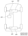
도 1은 본 발명에 따른 액티브 서스펜션 제어유닛의 개략적인 개념도이고,
도 2는 본 발명에 따른 액티브 서스펜션 제어유닛의 구조도이며,
도 3은 본 발명에 따른 액티브 서스펜션 제어방법의 순서도이고,
도 4는 본 발명에 따른 액티브 서스펜션 제어유닛 및 제어방법을 사용했을 때의 수직력 유동이 감소된 모습을 나타낸 도면이다.1 is a schematic conceptual diagram of an active suspension control unit according to the present invention,
2 is a structural diagram of an active suspension control unit according to the present invention,
3 is a flowchart of an active suspension control method according to the present invention,
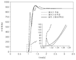
4 is a view showing a state in which the vertical force flow is reduced when using the active suspension control unit and control method according to the present invention.
여기서 사용되는 전문용어는 단지 특정 실시예를 언급하기 위한 것이며, 본 발명을 한정하는 것을 의도하지 않는다. 여기서 사용되는 단수 형태들은 문구들이 이와 명백히 반대의 의미를 나타내지 않는 한 복수 형태들도 포함한다. 명세서에서 사용되는 "포함하는"의 의미는 특정 특성, 영역, 정수, 단계, 동작, 요소 및/또는 성분을 구체화하며, 다른 특정 특성, 영역, 정수, 단계, 동작, 요소, 성분 및/또는 군의 존재나 부가를 제외시키는 것은 아니다.The terminology used herein is for the purpose of referring only to specific embodiments and is not intended to limit the invention. The singular forms used herein also include plural forms unless the phrases clearly indicate the opposite. As used herein, the meaning of “comprising” embodies certain properties, regions, integers, steps, actions, elements and/or components, and other specific properties, regions, integers, steps, actions, elements, components and/or groups It does not exclude the existence or addition of.
다르게 정의하지는 않았지만, 여기에 사용되는 기술용어 및 과학용어를 포함하는 모든 용어들은 본 발명이 속하는 기술분야에서 통상의 지식을 가진 자가 일반적으로 이해하는 의미와 동일한 의미를 가진다. 보통 사용되는 사전에 정의된 용어들은 관련기술문헌과 현재 개시된 내용에 부합하는 의미를 가지는 것으로 추가 해석되고, 정의되지 않는 한 이상적이거나 매우 공식적인 의미로 해석되지 않는다.Although not defined differently, all terms including technical terms and scientific terms used herein have the same meaning as those generally understood by those skilled in the art to which the present invention pertains. Commonly used dictionary-defined terms are further interpreted as having meanings consistent with related technical documents and currently disclosed contents, and are not interpreted as ideal or very formal meanings unless defined.
이하, 첨부된 도면을 참조하여 본 발명의 바람직한 실시예에 의한 액티브 서스펜션 제어유닛 및 액티브 서스펜션 제어방법에 대하여 설명하기로 한다.Hereinafter, an active suspension control unit and an active suspension control method according to a preferred embodiment of the present invention will be described with reference to the accompanying drawings.
먼저 액티브 서스펜션 제어유닛에 대해 설명하도록 한다. 도 1은 본 발명에 따른 액티브 서스펜션 제어유닛의 개략적인 개념도이고, 도 2는 본 발명에 따른 액티브 서스펜션 제어유닛의 구조도이다.First, the active suspension control unit will be described. 1 is a schematic conceptual diagram of an active suspension control unit according to the present invention, and FIG. 2 is a structural diagram of an active suspension control unit according to the present invention.
도 1 및 도 2에 도시된 바와 같이, 본 발명에 따른 제어유닛은 크게 제1제어부(100), 제2제어부(200) 및 이들에 의해 제어되는 액츄에이터(300)를 포함하여 구성된다.1 and 2, the control unit according to the present invention is largely composed of a
본 발명은 특히 ARS(Active Roll Stabilization)가 적용된 타입의 서스펜션에 설치되어 이를 제어하기 위한 발명이다. 제1제어부(100)는 차량의 중심 제어부로서, 예를 들어 ECU(Electronic control unit)일 수 있다. 제1제어부(100)에서는 차량에 장착되어 있는 여러 종류의 센서 등에서 정보를 수신받아 제어 신호를 발생시킨다. 예를 들어 차량상태 추정모듈은 서스펜션 수직속도를 추정하여 이를 제1제어부(100)에 전송하고, 제1제어부(100)에서는 이를 토대로 액츄에이터(300)에 제어신호를 전송할 수 있다.The present invention is an invention for controlling this by being installed on a suspension of a type in which ARS (Active Roll Stabilization) is applied. The
이때, 차량상태 추정모듈은 예를 들어 차체와 휠에 각각 설치되어 있는 가속도센서로부터 측정된 차체 수직가속도와 휠 수직가속도를 적분하여, 서스펜션 수직속도를 추정할 수 있다.At this time, the vehicle condition estimation module may estimate the suspension vertical velocity by integrating the vertical acceleration of the vehicle body and the vertical acceleration of the wheel measured from, for example, an acceleration sensor installed on the vehicle body and the wheel.
또한, 이하 본 발명의 상세한 설명에서는 액츄에이터(300)를 모터, 감속기, 부시로 구성된 하드웨어로 설정하여 작성되었지만, 본 발명은 이에 한정되지 않고, 유압식 장치 또는 모터-웜기어 형식으로 연결된 구조를 적용할 수도 있다.In addition, in the following detailed description of the present invention, the
제1제어부(100)는 차량이 직진 주행 중인지 선회 주행 중인지, 도로 상태가 평탄한지 험난한지, 차량 속도가 어느 정도인지를 파악한 후, 미리 설정되어 있는 데이터베이스에서 서스펜션 수직력 목표값을 산출한다. 이렇게 산출된 서스펜션 수직력 목표값은 후술할 제2제어부(200)에서 활용하게 된다.The
제1제어부(100)만으로 액츄에이터(300)를 제어할 경우, 차량의 거동에 의해 발생되는 신호를 연산하여 제어신호를 송출한 후, 액츄에이터(300)가 작동하여 차량의 거동이 변화하고, 이로 인하여 변경된 차량의 거동 신호를 다시 연산하여 액츄에이터(300)의 제어신호를 변경 송출하는 사이클에서 딜레이가 발생하게 된다. 따라서, 보다 즉각적인 응답성을 나타내어 딜레이를 최소화시킬 수 있도록 후술할 제2제어부(200)를 적용해야 한다.When the
제2제어부(200)는 수직력 목표값 및 외란값에 기초하여 액츄에이터(300)의 목표 제어값을 결정한다.The
제2제어부(200)는 제1제어부(100)에서 전송받은 서스펜션 수직력 목표값과 차량상태 추정모듈에서 계산된 좌륜과 우륜의 서스펜션 수직속도 차이값인 외란값을 이용하여 액츄에이터(300)의 최종목표제어값을 계산하게 된다. 이때, 서스펜션 수직력 목표값을 통해 계산된 제1목표제어값과 외란값을 통해 계산된 제2목표제어값을 합산하여, 최종목표제어값을 계산하게 된다.The
제2제어부(200)는 제1제어부(100)에서 차량 우륜의 서스펜션 수직력 목표값을 입력받고, 하기 식 1을 이용하여 우륜에 대한 액츄에이터(300)의 제1목표제어값을 계산하게 된다.The
식 1: τGc=GcFR,d / τGc=GcFL,d Equation 1: τ Gc =G c F R,d / τ Gc =G c F L,d
단, τGc는 제2제어부 제1목표제어값, Gc는 제2제어부의 피드백 제어함수, FR,d는 우륜 서스펜션 수직력 목표값, FL,d는 좌륜 서스펜션 수직력 목표값이다. 이때 Gc는 식 1-1에 의해 정의되고, FR,d는 제1제어부(100)로부터 정해진 값을 전송받게 된다.However, τ Gc is the first target control value of the second control unit, G c is the feedback control function of the second control unit, F R,d is the target value of the right wheel suspension vertical force, and F L,d is the target value of the left wheel suspension vertical force. At this time, G c is defined by Equation 1-1, and F R,d receives a predetermined value from the
식 1-1: Gc=Y1/SEquation 1-1: G c =Y 1 /S
단, Y1은 제2제어부의 오픈 루프 제어함수이고, S는 민감도 함수로서 식 1-2 내지 1-4로 정의된다.However, Y 1 is an open loop control function of the second control unit, and S is a sensitivity function defined by Equations 1-2 to 1-4.
식 1-2: S=1-TEquation 1-2: S=1-T
식 1-3: T=1/(τs+1)2 Equation 1-3: T=1/(τs+1) 2
식 1-4: τ=1/2πfEquation 1-4: τ=1/2πf
단, T는 목표 전달함수, τ는 시간 상수, s는 라플라스 연산자, f는 컷오프 주파수를 의미한다.However, T is the target transfer function, τ is the time constant, s is the Laplace operator, and f is the cutoff frequency.
이때, T는 Y1H4로 표현할 수도 있다. H4는 ARS 액츄에이터 하드웨어의 전달함수 중 하나로서, ARS 액츄에이터 하드웨어의 전달함수는 아래와 같다.At this time, T may be represented by Y 1 H4. H4 is one of the transfer functions of the ARS actuator hardware, and the transfer function of the ARS actuator hardware is as follows.
H1=FL/τmotor H1=F L /τ motor
H2=FL/VL H2=F L /V L
H3=FL/VR H3=F L /V R
H4=FR/τmotor H4=F R /τ motor
H5=FR/VL H5=F R /V L
H6=FR/VR H6=F R /V R
단, FL은 좌륜 서스펜션 수직력(relative suspension vertical force), FR은 우륜 서스펜션 수직력, VL은 좌륜 서스펜션 수직속도(relative suspension vertical velocity), VR은 우륜 서스펜션 수직속도, τmotor는 액츄에이터의 최종목표제어값(τGc+τY2)을 의미한다. 이때, τY2에 대해서는 후술한다.However, F L is the relative suspension vertical force, F R is the right wheel suspension vertical force, V L is the left suspension vertical velocity, V R is the right wheel suspension vertical velocity, τ motor is the final actuator It means the target control value (τ Gc +τ Y2 ). At this time, τ Y2 will be described later.
결과적으로, 제2제어부(200)에서 계산된 우륜의 서스펜션 수직력과 최종목표제어값은 다음과 같이 계산된다.As a result, the suspension vertical force of the right wheel and the final target control value calculated by the
FR=H4τmotor+H5VL+H6VR F R =H4τ motor +H5V L +H6V R
τmotor=H4-1(FR-H5VL-H6VR)τ motor =H4 -1 (F R -H5V L -H6V R )
상술한 바와 같이, 본 발명의 상세한 설명에서는 우륜의 서스펜션 수직력 목표값을 기반으로 제1목표제어값을 계산하는 것으로 설명되어 있지만, 본 발명은 이에 한정되지 않고, 좌륜의 서스펜션 수직력 목표값을 기반으로 제1목표제어값을 계산할 수도 있다.As described above, in the detailed description of the present invention, it is described as calculating the first target control value based on the suspension vertical force target value of the right wheel, but the present invention is not limited thereto, and based on the suspension vertical force target value of the left wheel. The first target control value may be calculated.
이 경우, 식 H4를 식 H1으로 치환하고, 식 H5를 식 H2로 치환하며, 식 H6를 식 H3으로 치환하여, FR 및 VR을 계산할 수 있을 것이다.In this case, F R and V R may be calculated by substituting Equation H4 for Equation H1, substituting Equation H5 by Equation H2, and substituting Equation H6 by Equation H3.
한편, 제2제어부(200)는 수직속도 추정모듈로부터 우륜 서스펜션 수직속도와 좌륜 서스펜션 수직속도를 각각 입력받을 수 있다. 이때 수직속도 추정모듈은 차체 가속도센서와 휠 가속도센서에서 측정된 가속도를 적분하여 서스펜션 수직속도를 추정할 수 있다.Meanwhile, the
제2제어부(200)는 우륜 서스펜션 수직속도와 좌륜 서스펜션 수직속도를 각각 입력받아 그 차이인 외란값(VR-VL)을 계산하고, 하기 식 2를 이용하여 액츄에이터(300)의 제2목표제어값을 계산하게 된다.The
식 2: τY2=Y2(VR-VL)Equation 2: τ Y2 =Y 2 (V R -V L )
단, τY2는 제2제어부 제2목표제어값, Y2는 제2제어부의 제어함수, VR은 우륜 서스펜션 수직속도, VL은 좌륜 서스펜션 수직속도이다. 또한, Y2는 하기 식 2-1에 의해 계산되고, VR 및 VL은 하기 식 2-2 및 2-3와 같이 계산된다.However, τ Y2 is the second target control value of the second control unit, Y 2 is the control function of the second control unit, V R is the right wheel suspension vertical speed, and V L is the left wheel suspension vertical speed. In addition, Y 2 is calculated by the following formula 2-1, and V R and V L are calculated by the following formulas 2-2 and 2-3.
식 2-1: Y2=-H4- 1H6/(τs+1)2 Expression 2-1: Y 2 = -H4 - 1 H6 / (τs + 1) 2
식 2-2: VR=Vus,R-Vs,R Equation 2-2: V R =V us,R -V s,R
식 2-3: VL=Vus,L-Vs,L Equation 2-3: V L =V us,L -V s,L
단, Vus,R은 우륜 언스프렁매스(unsprung mass) 수직속도, Vs,R은 우륜 스프렁매스(sprung mass) 수직속도, Vus,L은 좌륜 언스프렁매스(unsprung mass) 수직속도, Vs,L은 좌륜 스프렁매스(sprung mass) 수직속도이다.However, V us,R is the right wheel unsprung mass vertical speed, V s,R is the right wheel sprung mass vertical speed, and V us,L is the left wheel unsprung mass vertical speed. The velocity, V s,L, is the left wheel sprung mass vertical velocity.
즉, 서스펜션 수직속도는 언스프렁매스(예를 들어, 휠) 수직속도와 스프렁매스(예를 들어, 차체) 수직속도의 차이로 계산되고, 외란값은 좌륜과 우륜의 서스펜션 수직속도의 차이로 계산된다. 즉, 외란은 좌륜과 우륜의 높이 및 승강 속도의 차이에 의해 발생되는 바, 예를 들어 험로를 주행하거나 둔턱을 넘을 때 발생할 수 있다.That is, the suspension vertical speed is calculated as the difference between the vertical speed of the unsprung mass (eg, wheel) and the vertical speed of the sprung mass (eg, the vehicle body), and the disturbance value is the difference between the suspension vertical speed of the left and right wheels. Is calculated as That is, the disturbance is caused by a difference between the height of the left wheel and the right wheel and the lifting speed, and may occur, for example, when driving on a rough road or crossing a hillside.
정리하면, 최종적인 액츄에이터(300)의 출력(모터 토크)은 하기 식 3과 같이 제2제어부(200)에서 각각 계산된 제1목표제어값 및 제2목표제어값을 합산하여 결정된다.In summary, the output (motor torque) of the
식 3: τmotor=τGc+τY2 Equation 3: τ motor =τ Gc +τ Y2
상술한 바와 같이 구성된 액티브 서스펜션 제어유닛은 차량의 전륜 또는 후륜 중 어느 하나에 적용될 수도 있고, 전륜과 후륜에 모두 적용될 수 있다. 즉, 전륜액츄에이터(310)에 전륜제2제어부(210)를 설치하고, 후륜액츄에이터(320)에 후륜제2제어부(220)를 설치할 수 있을 것이다.The active suspension control unit configured as described above may be applied to either the front or rear wheels of the vehicle, or may be applied to both the front and rear wheels. That is, the front wheel
한편, 제2제어부(200)에서는 하나의 제어기로 제1목표제어값 및 제2목표제어값을 계산할 수도 있지만, 별도로 구성된 두 개의 제어기를 통해 제1목표제어값과 제2목표제어값을 각각 계산할 수도 있을 것이다.On the other hand, the
도 3은 본 발명에 따른 액티브 서스펜션 제어방법의 순서도이고, 도 4는 본 발명에 따른 액티브 서스펜션 제어유닛 및 제어방법을 사용했을 때의 수직력 유동이 감소된 모습을 나타낸 도면이다.3 is a flowchart of an active suspension control method according to the present invention, and FIG. 4 is a view showing a state in which the vertical force flow is reduced when using the active suspension control unit and control method according to the present invention.
도 1 내지 도 4에 도시된 바와 같이, 본 발명에 따른 액티브 서스펜션 제어방법은, 주행 상황에 따라 서스펜션 수직력 목표값을 산출하는 단계, 우륜 서스펜션 수직속도와 좌륜 서스펜션 수직속도를 추정하여 외란값을 산출하는 단계, 서스펜션 수직력 목표값을 이용하여 액츄에이터의 제1목표제어값을 계산하고, 외란값을 이용하여 액츄에이터의 제2목표제어값을 계산하며, 액츄에이터의 제1목표제어값 및 제2목표제어값을 합산하여 액츄에이터의 최종목표제어값을 계산하는 단계 및 계산된 액츄에이터의 최종목표제어값을 이용하여 액츄에이터를 작동시키는 단계를 포함하여 구성된다.As shown in Figures 1 to 4, the active suspension control method according to the present invention, calculating the target value of the suspension vertical force in accordance with the driving situation, the right wheel suspension vertical speed and the left wheel suspension vertical speed is estimated to calculate the disturbance value The first target control value of the actuator is calculated using the suspension vertical force target value, the second target control value of the actuator is calculated using the disturbance value, and the first and second target control values of the actuator are calculated. Comprising the step of calculating the final target control value of the actuator and operating the actuator using the calculated final target control value of the actuator.
서스펜션 수직력 목표값을 산출하는 단계에서는, 제1제어부(100)에서 차량의 속도, 선회각, 노면 상태 등을 종합적으로 고려하여 미리 저장되어 있는 프로파일에서 좌륜 및 우륜에 대한 서스펜션 수직력 목표값을 산출한다.In the step of calculating the suspension vertical force target value, the
외란값을 산출하는 단계에서는, 차량상태 추정모듈에서 서스펜션 수직가속도를 적분하여 서스펜션 수직속도를 추정하고, 좌륜과 우륜의 서스펜션 수직속도의 차이를 이용하여 외란값을 산출한다.In the step of calculating the disturbance value, the suspension vertical acceleration is estimated by integrating the suspension vertical acceleration in the vehicle condition estimation module, and the disturbance value is calculated using the difference between the suspension vertical speed of the left and right wheels.
액츄에이터의 최종목표제어값을 계산하는 단계에서는, 서스펜션 수직력 목표값을 산출하는 단계에서 발생된 정보와, 외란값을 산출하는 단계에서 발생된 정보를 이용하여 액츄에이터의 최종목표제어값을 계산하게 된다.In the step of calculating the final target control value of the actuator, the final target control value of the actuator is calculated using the information generated in the step of calculating the suspension vertical force target value and the information generated in the step of calculating the disturbance value.
구체적으로는, 제1제어부(100)에서 전달된 서스펜션 수직력 목표값에 대응하기 위한 액츄에이터(300)의 제1목표제어값 및 차량상태 추정모듈에서 전달된 외란값에 대응하기 위한 서스펜션 수직력 및 액츄에이터(300) 제2목표제어값을 제2제어부(200)에서 각각 계산하여, 제1목표제어값 및 제2목표제어값을 합산하여 액츄에이터(300)의 최종목표제어값을 계산하게 된다.Specifically, the suspension vertical force and the actuator for responding to the first target control value of the
만약 제2제어부(200)가 없다면, 이너시아(inertia) 및 댐핑 요소들에서 발생하는 지연시간으로 인해 0.2초 정도의 제어 딜레이가 발생하게 된다. 이러한 딜레이를 탑승자가 인지하면 출렁임이나 진동 등의 불편을 경험하게 되므로, 종래에는 초기 반응시 액츄에이터 출력을 과도하게 높이거나 별도의 제어전략을 추가하는 방법을 사용하였다.If there is no
도 4에 도시된 바와 같이, 서브제어부(200)를 사용하지 않을 경우 액츄에이터(300)의 하드웨어적 특성 때문에 목표로 하는 종래의 스텝바 반응성과 차이를 나타내게 되고, 이는 탑승자에게 이질감을 발생시킬 뿐만 아니라 과도한 흔들림이 유발될 수 있다.As shown in FIG. 4, when the sub-controller 200 is not used, it exhibits a difference from the targeted step bar responsiveness due to the hardware characteristics of the
따라서, 본 발명에서는 제2제어부(200)를 통해 딜레이를 최소화하면서, 종래의 스텝바와 유사한 반응성을 나타낼 수 있도록 액츄에이터(300)의 출력을 제어함으로써, 탑승자의 안락감을 향상시킴과 함께 둔턱이나 험로 주행시에도 안정적인 주행 성능을 나타낼 수 있게 된다.Therefore, in the present invention, by controlling the output of the
액츄에이터를 작동시키는 단계에서는, 앞서 계산된 최종적인 액츄에이터 출력을 액츄에이터(300)에 인가하여 작동시킴으로써, 차량의 실내공간에 전달되는 흔들림, 진동 등을 최소화시키게 된다.In the step of operating the actuator, the final calculated actuator output is applied to the
또한, 외란값을 산출하는 단계, 액츄에이터의 최종목표제어값을 계산하는 단계에서의 세부적인 제어 방법은 앞서 설명한 액티브 서스펜션 제어유닛에 대한 설명으로 갈음하도록 한다.In addition, the detailed control method in the step of calculating the disturbance value and the step of calculating the final target control value of the actuator is replaced with the description of the active suspension control unit described above.
이상 첨부된 도면을 참조하여 본 발명의 실시예를 설명하였지만, 본 발명이 속하는 기술분야에서 통상의 지식을 가진 자는 본 발명이 그 기술적 사상이나 필수적인 특징을 변경하지 않고서 다른 구체적인 형태로 실시될 수 있다는 것을 이해할 수 있을 것이다.Although the embodiments of the present invention have been described with reference to the accompanying drawings, those skilled in the art to which the present invention pertains may be implemented in other specific forms without changing the technical spirit or essential features of the present invention. You will understand.
그러므로 이상에서 기술한 실시예들은 모든 면에서 예시적인 것이며 한정적이 아닌 것으로 이해해야만 한다. 본 발명의 범위는 상기 상세한 설명보다는 후술하는 특허청구범위에 의하여 나타내어지며, 특허청구범위의 의미 및 범위 그리고 그 균등 개념으로부터 도출되는 모든 변경 또는 변경된 형태가 본 발명의 범위에 포함되는 것으로 해석되어야 한다.Therefore, it should be understood that the embodiments described above are illustrative in all respects and not restrictive. The scope of the present invention is indicated by the following claims rather than the above detailed description, and all changes or modified forms derived from the meaning and scope of the claims and equivalent concepts should be interpreted to be included in the scope of the present invention. .
100: 제1제어부
200: 제2제어부
210: 전륜제2제어부
220: 후륜제2제어부
300: 액츄에이터
310: 전륜액츄에이터
320: 후륜액츄에이터100: first control unit
200: second control unit
210: front wheel second control unit
220: rear wheel second control unit
300: actuator
310: front wheel actuator
320: rear wheel actuator
Claims (12)
센서로 입력받는 정보를 통해 주행 상황을 판단하고, 주행 상황에 따라 미리 설정된 서스펜션 수직력 목표값과, 좌륜과 우륜의 서스펜션 수직속도 차이에 의해 발생되는 외란값을 이용하여 액츄에이터의 최종목표제어값을 계산하는 제어부;를 포함하는 액티브 서스펜션 제어유닛.
ARS (Active Roll Stabilization) structure is provided with an actuator that variably controls the reaction characteristics of the suspension; And
The driving condition is judged through the information received by the sensor, and the final target control value of the actuator is calculated using a preset suspension vertical force target value and a disturbance value generated by the difference in the suspension vertical speed of the left and right wheels according to the driving situation. The active suspension control unit comprising a.
제어부는 서스펜션 수직력 목표값을 출력하는 제1제어부; 및
제1제어부에서 전송받은 서스펜션 수직력 목표값을 통해 계산된 제1목표제어값 및 외란값을 이용하여 계산된 제2목표제어값을 합산하여 최종목표제어값을 계산하는 제2제어부;를 포함하는 것을 특징으로 하는 액티브 서스펜션 제어유닛.
The method according to claim 1,
The control unit includes a first control unit for outputting a suspension vertical force target value; And
The second control unit calculates a final target control value by summing the first target control value calculated using the suspension vertical force target value received from the first control unit and the second target control value calculated using the disturbance value; Features an active suspension control unit.
제2제어부는 제1제어부에서 좌륜 또는 우륜 중 적어도 어느 하나의 서스펜션 수직력 목표값을 입력받고, 하기 식 1을 이용하여 액츄에이터의 제1목표제어값을 계산하는 것을 특징으로 하는 액티브 서스펜션 제어유닛.
식 1: τGc=GcFR,d / τGc=GcFL,d
단, τGc는 제2제어부 제1목표제어값, Gc는 제2제어부의 제어함수, FR,d는 우륜 서스펜션 수직력 목표값, FL,d는 좌륜 서스펜션 수직력 목표값이다.
The method according to claim 2,
The second control unit receives the suspension vertical force target value of at least one of the left wheel or the right wheel from the first control unit, and calculates the first target control value of the actuator using Equation 1 below.
Equation 1: τ Gc =G c F R,d / τ Gc =G c F L,d
However, τ Gc is the first target control value of the second control unit, G c is the control function of the second control unit, F R,d is the target value of the right wheel suspension vertical force, and F L,d is the target value of the left wheel suspension vertical force.
제2제어부는 우륜 서스펜션 수직속도와 좌륜 서스펜션 수직속도를 각각 입력받아 외란값(VR-VL)을 계산하고, 하기 식 2를 이용하여 액츄에이터의 제2목표제어값을 계산하는 것을 특징으로 하는 액티브 서스펜션 제어유닛.
식 2: τY2=Y2(VR-VL)
단, τY2는 제2제어부 제2목표제어값, Y2는 제2제어부의 제어함수, VR은 우륜 서스펜션 수직속도, VL은 좌륜 서스펜션 수직속도이다.
The method according to claim 2,
The second control unit receives the right wheel suspension vertical speed and the left wheel suspension vertical speed, respectively, calculates the disturbance value (V R -V L ), and calculates the second target control value of the actuator using Equation 2 below. Active suspension control unit.
Equation 2: τ Y2 =Y 2 (V R -V L )
However, τ Y2 is the second target control value of the second control unit, Y 2 is the control function of the second control unit, V R is the right wheel suspension vertical speed, and V L is the left wheel suspension vertical speed.
제2제어부는 수직속도 추정모듈로부터 우륜 서스펜션 수직속도와 좌륜 서스펜션 수직속도를 각각 입력받는 것을 특징으로 하는 액티브 서스펜션 제어유닛.
The method according to claim 4,
The second control unit is an active suspension control unit, characterized in that the input of the right wheel suspension vertical speed and the left wheel suspension vertical speed respectively from the vertical speed estimation module.
수직속도 추정모듈은 차체 가속도센서와 휠 가속도센서에서 측정된 가속도 차이를 이용하여 서스펜션 수직속도를 추정하는 것을 특징으로 하는 액티브 서스펜션 제어유닛.
The method according to claim 5,
The vertical speed estimation module is an active suspension control unit characterized in that it estimates the suspension vertical speed using the difference in acceleration measured by the vehicle acceleration sensor and the wheel acceleration sensor.
제2제어부는 서스펜션 수직력 목표값을 이용하여 계산된 액츄에이터의 제1목표제어값과, 외란값을 이용하여 계산된 액츄에이터의 제2목표제어값을 합산하여 최종목표제어값을 계산하는 것을 특징으로 하는 액티브 서스펜션 제어유닛.
The method according to claim 2,
The second control unit calculates a final target control value by summing the first target control value of the actuator calculated using the suspension vertical force target value and the second target control value of the actuator calculated using the disturbance value. Active suspension control unit.
우륜 서스펜션 수직속도와 좌륜 서스펜션 수직속도를 추정하여 외란값을 산출하는 단계;
서스펜션 수직력 목표값을 이용하여 액츄에이터의 제1목표제어값을 계산하고, 외란값을 이용하여 액츄에이터의 제2목표제어값을 계산하며, 제1목표제어값 및 제2목표제어값을 합산하여 최종목표제어값을 계산하는 단계; 및
계산된 액츄에이터의 최종목표제어값을 이용하여 액츄에이터를 작동시키는 단계;를 포함하는 액티브 서스펜션 제어방법.
Calculating a suspension vertical force target value according to the driving situation;
Calculating a disturbance value by estimating the right wheel suspension vertical speed and the left wheel suspension vertical speed;
The first target control value of the actuator is calculated using the suspension vertical force target value, the second target control value of the actuator is calculated using the disturbance value, and the first target control value and the second target control value are added to the final target. Calculating a control value; And
And operating the actuator using the calculated final target control value of the actuator.
액츄에이터의 최종목표제어값을 계산하는 단계는 하기 식1을 이용하여 서스펜션 수직력 목표값으로부터 액츄에이터의 제1목표제어값을 계산하고, 하기 식 2를 이용하여 외란값으로부터 액츄에이터의 제2목표제어값을 계산하는 것을 특징으로 하는 액티브 서스펜션 제어방법.
식 1: τGc=GcFc,R
식 2: τY2=Y2(VR-VL)
단, τGc는 제2제어부 제1목표제어값, Gc는 제2제어부의 제어함수, Fc는 우륜 서스펜션 수직력 목표값, τY2는 제2제어부 제2목표제어값, Y2는 제2제어부의 제어함수, VR은 우륜 서스펜션 수직속도, VL은 좌륜 서스펜션 수직속도이다.
The method according to claim 8,
The step of calculating the final target control value of the actuator is to calculate the first target control value of the actuator from the suspension vertical force target value using Equation 1 below, and to calculate the second target control value of the actuator from the disturbance value using Equation 2 below. Active suspension control method characterized in that the calculation.
Equation 1: τ Gc =G c F c,R
Equation 2: τ Y2 =Y 2 (V R -V L )
However, τ Gc is the first target control value of the second control unit, G c is the control function of the second control unit, F c is the target value of the right-hand suspension vertical force, τ Y2 is the second target control value of the second control unit, and Y 2 is the second target value. The control function of the controller, V R is the right wheel suspension vertical speed, and V L is the left wheel suspension vertical speed.
서스펜션 수직력 목표값을 산출하는 단계는 주행 상황에 따라 미리 설정된 서스펜션 수직력 목표값을 출력하는 것을 특징으로 하는 액티브 서스펜션 제어방법.
The method according to claim 8,
The step of calculating the suspension vertical force target value is an active suspension control method comprising outputting a preset suspension vertical force target value according to a driving situation.
외란값을 산출하는 단계는 우륜 서스펜션 수직속도와 좌륜 서스펜션 수직속도의 차이를 계산하여 외란값을 출력하는 것을 특징으로 하는 액티브 서스펜션 제어방법.
The method according to claim 8,
The step of calculating the disturbance value is an active suspension control method characterized in that it calculates the difference between the right wheel suspension vertical speed and the left wheel suspension vertical speed and outputs the disturbance value.
외란값을 산출하는 단계는 차체의 가속도와 휠의 가속도 차이를 이용하여 우륜 서스펜션 수직속도와 좌륜 서스펜션 수직속도를 각각 추정하는 것을 특징으로 하는 액티브 서스펜션 제어방법.
The method according to claim 11,
The step of calculating the disturbance value is an active suspension control method characterized by estimating the right wheel suspension vertical speed and the left wheel suspension vertical speed, respectively, using the difference between the acceleration of the vehicle body and the acceleration of the wheel.
Priority Applications (4)
| Application Number | Priority Date | Filing Date | Title |
|---|---|---|---|
| KR1020180156325A KR102589031B1 (en) | 2018-12-06 | 2018-12-06 | Control unit of active suspension and control method of active suspension |
| US16/414,528 US11052718B2 (en) | 2018-12-06 | 2019-05-16 | Active suspension control unit and method |
| DE102019114824.3A DE102019114824A1 (en) | 2018-12-06 | 2019-06-03 | ACTIVE SUSPENSION CONTROL UNIT AND METHOD |
| CN201910496510.5A CN111284287A (en) | 2018-12-06 | 2019-06-10 | Active suspension control unit and method |
Applications Claiming Priority (1)
| Application Number | Priority Date | Filing Date | Title |
|---|---|---|---|
| KR1020180156325A KR102589031B1 (en) | 2018-12-06 | 2018-12-06 | Control unit of active suspension and control method of active suspension |
Publications (2)
| Publication Number | Publication Date |
|---|---|
| KR20200069450A true KR20200069450A (en) | 2020-06-17 |
| KR102589031B1 KR102589031B1 (en) | 2023-10-17 |
Family
ID=70776433
Family Applications (1)
| Application Number | Title | Priority Date | Filing Date |
|---|---|---|---|
| KR1020180156325A KR102589031B1 (en) | 2018-12-06 | 2018-12-06 | Control unit of active suspension and control method of active suspension |
Country Status (4)
| Country | Link |
|---|---|
| US (1) | US11052718B2 (en) |
| KR (1) | KR102589031B1 (en) |
| CN (1) | CN111284287A (en) |
| DE (1) | DE102019114824A1 (en) |
Families Citing this family (3)
| Publication number | Priority date | Publication date | Assignee | Title |
|---|---|---|---|---|
| DE102020111915B3 (en) * | 2020-05-04 | 2021-06-24 | Dr. Ing. H.C. F. Porsche Aktiengesellschaft | Procedure for determining vehicle parameters |
| US11865891B2 (en) | 2020-10-30 | 2024-01-09 | GM Global Technology Operations LLC | Method and system for active roll control |
| CN115214281B (en) * | 2021-11-12 | 2023-12-15 | 广州汽车集团股份有限公司 | Vehicle suspension adjusting method, device and storage medium |
Citations (5)
| Publication number | Priority date | Publication date | Assignee | Title |
|---|---|---|---|---|
| JP2005238971A (en) * | 2004-02-26 | 2005-09-08 | Aisin Seiki Co Ltd | Stabilizer controlling device |
| JP2005255152A (en) | 2004-02-12 | 2005-09-22 | Hitachi Ltd | Suspension control device |
| JP2010126044A (en) * | 2008-11-28 | 2010-06-10 | Nissan Motor Co Ltd | Suspension control device, and suspension control method |
| US20120310479A1 (en) * | 2010-02-17 | 2012-12-06 | Toyota Jidosha Kabushiki Kaisha | Damping force control device for vehicle |
| JP2016104605A (en) * | 2014-12-01 | 2016-06-09 | トヨタ自動車株式会社 | Control device of vehicle |
Family Cites Families (15)
| Publication number | Priority date | Publication date | Assignee | Title |
|---|---|---|---|---|
| US5510986A (en) * | 1994-03-14 | 1996-04-23 | Trw Inc. | Method and apparatus for controlling an active suspension system |
| JP2001047835A (en) * | 1999-08-11 | 2001-02-20 | Nissan Motor Co Ltd | Active suspension |
| JP2004216954A (en) * | 2003-01-10 | 2004-08-05 | Hitachi Ltd | Traveling control device for vehicle |
| DE102006001436B4 (en) * | 2006-01-10 | 2009-08-13 | Zf Friedrichshafen Ag | Method for determining at least one movement state of a vehicle body |
| KR101297961B1 (en) * | 2006-10-25 | 2013-08-19 | 현대모비스 주식회사 | Toe control apparatus for active geometry control rear suspension in vehicle and control method thereof |
| JP4920006B2 (en) * | 2008-05-15 | 2012-04-18 | トヨタ自動車株式会社 | Vehicle suspension system |
| JP4935757B2 (en) * | 2008-05-27 | 2012-05-23 | トヨタ自動車株式会社 | Vehicle suspension system |
| DE102010048260B4 (en) * | 2010-10-12 | 2016-03-10 | Volkswagen Ag | Automatic determination of a compression travel of a wheel of a vehicle |
| US8918253B2 (en) * | 2012-06-25 | 2014-12-23 | Ford Global Technologies, Llc | Ride performance optimization in an active suspension system |
| KR20160044362A (en) * | 2014-10-15 | 2016-04-25 | 현대자동차주식회사 | Method for controlling suspension system |
| JP6412409B2 (en) | 2014-11-07 | 2018-10-24 | Kyb株式会社 | Suspension device and suspension control device |
| JP6879661B2 (en) * | 2015-11-19 | 2021-06-02 | Kyb株式会社 | Suspension device |
| KR101916537B1 (en) * | 2016-11-14 | 2018-11-07 | 현대자동차주식회사 | Method for Cooperation Control of Chassis Integration System and Vehicle thereof |
| US11801726B2 (en) * | 2018-11-01 | 2023-10-31 | ClearMotion, Inc. | Vehicle control based on localization and road data |
| KR102614170B1 (en) * | 2018-12-06 | 2023-12-14 | 현대자동차주식회사 | Damper control method for vehicle |
-
2018
- 2018-12-06 KR KR1020180156325A patent/KR102589031B1/en active IP Right Grant
-
2019
- 2019-05-16 US US16/414,528 patent/US11052718B2/en active Active
- 2019-06-03 DE DE102019114824.3A patent/DE102019114824A1/en active Pending
- 2019-06-10 CN CN201910496510.5A patent/CN111284287A/en active Pending
Patent Citations (5)
| Publication number | Priority date | Publication date | Assignee | Title |
|---|---|---|---|---|
| JP2005255152A (en) | 2004-02-12 | 2005-09-22 | Hitachi Ltd | Suspension control device |
| JP2005238971A (en) * | 2004-02-26 | 2005-09-08 | Aisin Seiki Co Ltd | Stabilizer controlling device |
| JP2010126044A (en) * | 2008-11-28 | 2010-06-10 | Nissan Motor Co Ltd | Suspension control device, and suspension control method |
| US20120310479A1 (en) * | 2010-02-17 | 2012-12-06 | Toyota Jidosha Kabushiki Kaisha | Damping force control device for vehicle |
| JP2016104605A (en) * | 2014-12-01 | 2016-06-09 | トヨタ自動車株式会社 | Control device of vehicle |
Also Published As
| Publication number | Publication date |
|---|---|
| US11052718B2 (en) | 2021-07-06 |
| KR102589031B1 (en) | 2023-10-17 |
| CN111284287A (en) | 2020-06-16 |
| DE102019114824A1 (en) | 2020-06-10 |
| US20200180381A1 (en) | 2020-06-11 |
Similar Documents
| Publication | Publication Date | Title |
|---|---|---|
| JP5168567B2 (en) | State estimation device, suspension control device, and suspension system | |
| JP4515201B2 (en) | Vehicle stabilization control system | |
| US6922617B2 (en) | Vehicle control device and vehicle control method | |
| RU2637079C2 (en) | Oscillation control unit and oscillation control system | |
| KR20200069450A (en) | Control unit of active suspension and control method of active suspension | |
| JP2007527820A (en) | Method for controlling driving propulsion force of vehicle, apparatus for implementing the method, and use thereof | |
| JP2006335193A (en) | Rolling characteristic estimation device for vehicle, and rolling motion stabilization controller for vehicle using the same | |
| CN109203903B (en) | Suspension control system | |
| US20190039429A1 (en) | Vehicle attitude control device | |
| US8892303B2 (en) | Vehicle control device | |
| CN108216210B (en) | Vehicle stability control device | |
| JP6753911B2 (en) | Control device for variable damping force damper | |
| US20160304068A1 (en) | Braking force control device | |
| JP2010095211A (en) | Vehicular suspension device | |
| JP2019025989A (en) | Suspension control system | |
| JP2011016382A (en) | Damping force control device of vehicle | |
| JP2009078759A (en) | Suspension controller for vehicle | |
| JP2009078757A (en) | Road surface displacement inferring device for vehicle | |
| JP2001287528A (en) | Vehicular sprung speed assuming device | |
| JP5699588B2 (en) | Suspension control device | |
| JP2009078761A (en) | Suspension controller | |
| KR102402807B1 (en) | Method for estimating vehicle roll angle for active suspension control system | |
| KR20200129207A (en) | Active suspension control method of vehicle | |
| KR20190000643A (en) | Method and apparatus for improving response of active roll stabilizer for vehicle | |
| JP5157683B2 (en) | Suspension control device |
Legal Events
| Date | Code | Title | Description |
|---|---|---|---|
| A201 | Request for examination | ||
| E902 | Notification of reason for refusal | ||
| E701 | Decision to grant or registration of patent right | ||
| GRNT | Written decision to grant |