JP2010126044A - Suspension control device, and suspension control method - Google Patents
Suspension control device, and suspension control method Download PDFInfo
- Publication number
- JP2010126044A JP2010126044A JP2008304193A JP2008304193A JP2010126044A JP 2010126044 A JP2010126044 A JP 2010126044A JP 2008304193 A JP2008304193 A JP 2008304193A JP 2008304193 A JP2008304193 A JP 2008304193A JP 2010126044 A JP2010126044 A JP 2010126044A
- Authority
- JP
- Japan
- Prior art keywords
- stroke
- disturbance
- suspension
- correction amount
- correction
- Prior art date
- Legal status (The legal status is an assumption and is not a legal conclusion. Google has not performed a legal analysis and makes no representation as to the accuracy of the status listed.)
- Pending
Links
Images


Abstract
Description
本発明は、サスペンション制御装置、及びサスペンション制御方法に関する。 The present invention relates to a suspension control device and a suspension control method.
アクチュエータを駆動制御する場合、その駆動力を指令値どおりに発生させることが重要となる。例えばステアリングバイワイヤでは、運転者のステアリング操作に対して適度な反力を発生させるために反力モータを駆動制御するが、摩擦力等の外乱を補償するための外乱オブザーバを付加することにより、良好な操作フィーリングの実現を図るものがあった(特許文献1参照)。
しかしながら、外乱オブザーバを用いると、高周波領域における補償精度が低下することが一般に知られている。したがって、サスペンションのように、路面振動やエンジン振動によってストローク方向やストローク速度が絶えず変化する系では、前述したステアリング系よりも高周波領域の外乱が増大し、補償精度が低下すると考えられる。
本発明の課題は、サスペンション制御における外乱の補償精度を向上させることである。
However, it is generally known that when a disturbance observer is used, the compensation accuracy in the high frequency region is lowered. Therefore, in a system such as a suspension in which the stroke direction and the stroke speed are constantly changed by road surface vibration and engine vibration, it is considered that disturbance in the high frequency region increases and the compensation accuracy decreases compared to the steering system described above.
An object of the present invention is to improve the accuracy of disturbance compensation in suspension control.
本発明に係るサスペンション制御装置は、サスペンションのストロークを制御可能なアクチュエータに対して目標制御量を設定し、この目標制御量に応じてアクチュエータを駆動制御するものであって、目標制御量、及びサスペンションのストローク状態に基づいて第一の補正量を算出し、サスペンションのストローク状態に基づいて外乱を推定し、推定した外乱に基づいて第二の補正量を算出し、推定した外乱の周波数に基づいて第一の補正量を補正することで第三の補正量を算出し、これら第二の補正量及び第三の補正量に基づいて、前記目標制御量を補正することで外乱補償を行う。 A suspension control apparatus according to the present invention sets a target control amount for an actuator capable of controlling the stroke of a suspension, and controls the drive of the actuator according to the target control amount. The first correction amount is calculated based on the stroke state of the first, the disturbance is estimated based on the stroke state of the suspension, the second correction amount is calculated based on the estimated disturbance, and the frequency of the estimated disturbance is calculated. A third correction amount is calculated by correcting the first correction amount, and disturbance compensation is performed by correcting the target control amount based on the second correction amount and the third correction amount.
本発明に係るサスペンション制御装置によれば、サスペンション制御における外乱の補償精度を、高周波領域まで向上させることができる。 According to the suspension control device of the present invention, it is possible to improve disturbance compensation accuracy in suspension control up to a high frequency region.
以下、本発明の実施形態を図面に基づいて説明する。
《第一実施形態》
《構成》
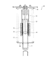
図1は、電磁式ショックアブソーバの概略構成である。
電磁式ショックアブソーバ10は、下端が車輪側に弾性支持された円筒状のシェルケース11と、このシェルケース11に進退可能に挿通され、上端が車体側に弾性支持されたロッド12と、このロッド12の上端側に固定され、シェルケース11の外周面に対向した内周面を有する外筒13と、を備える。
シェルケース11の内部には、ダンパーオイルが封入されており、シェルケース11とロッド12とが軸方向に相対変位するときに、ロッド12の下端に連結されたピストン14がダンパーオイルの流動抵抗を受けることで減衰力が発生する。
Hereinafter, embodiments of the present invention will be described with reference to the drawings.
<< first embodiment >>
"Constitution"
FIG. 1 is a schematic configuration of an electromagnetic shock absorber.
The electromagnetic shock absorber 10 has a
Damper oil is sealed inside the
シェルケース11の外周面には、リング状に形成された複数のマグネット15を軸方向に沿って列設し、外筒13の内周面には、リング状に形成された複数のコイルセル16を軸方向に沿って等間隔に固定する。これらマグネット15とコイルセル16とが、リニアモータとなり、各コイルセル16の励磁を制御し、軸方向に沿って移動磁界を発生させることで、励磁電流に応じた推力が発生し、シェルケース11とロッド12とが軸方向に相対変位する。
電磁式ショックアブソーバ10は、コイルスプリング17の内側に配置され、コイルスプリング17は、車体側に固定されたスプリングシート18と、シェルケース11の外周面に固定されたスプリングシート19とによって支持されている。
A plurality of
The
図2は、アクティブサスペンションのシステム構成である。
サスペンションリンクには、サスペンションのストローク位置を検出するストロークセンサ31が設けている。
電磁式ショックアブソーバ10は、例えばマイクロコンピュータで構成されるコントローラ40によって駆動制御される。
コントローラ40は、車両の走行状態に応じて電磁式ショックアブソーバ10の目標推力を算出する目標推力算出部41と、目標推力に応じて電磁式ショックアブソーバ10を駆動制御する駆動制御部42と、前記ストロークセンサが検出したストローク位置に基づいてストローク速度、及びストローク加速度を含めたストローク状態を算出する状態算出部43と、目標推力に応じて電磁式ショックアブソーバ10を駆動制御したときに、状態算出部43が算出したストローク状態に基づいて、以後、演算される目標推力に対して外乱補償を行う補償部44と、を備える。
FIG. 2 shows a system configuration of the active suspension.
The suspension link is provided with a
The
The
状態算出部43は、ストローク位置の微分によってストローク速度を演算し、ストローク速度の微分によってストローク加速度を演算する。なお、サスペンションリンクの上端及び下端の双方に加速度センサを設置し、夫々の検出値の差分に応じて、ストローク加速度を検出してもよい。
補償部44は、電磁式ショックアブソーバ10を駆動制御したときの目標推力、及び状態算出部43で検出したストローク状態に基づいて、第一の補正量を算出する外乱オブザーバ51と、状態算出部43で検出したストローク状態に基づいて外乱を推定する外乱推定部52と、この外乱推定部52が推定した外乱に基づいて第二の補正量を算出する第二の算出部53と、外乱推定部52が推定した外乱から高周波成分を抽出する一次のハイパスフィルタ54と、外乱オブザーバ51が算出した第一の補正量を、ハイパスフィルタ54によって抽出された外乱の高周波成分に基づいて補正することで第三の補正量を算出する第三の算出部55と、第二の算出部53が算出した第二の補正量、及び第三の算出部55が算出した第三の補正量を、以後、演算される目標制御量に加算して補正する加算器56と、を備える。
The
The
図3は、外乱推定部52の構成である。
外乱推定部52は、サスペンションのストローク状態と外乱の対応関係を記憶した記憶部61と、この記憶部61に記憶された対応関係を参照し、サスペンションのストローク状態に応じて外乱を演算する演算部62と、を備える。
記憶部61には、例えばストローク位置と電磁式ショックアブソーバ10のコギング力との対応関係、ストローク位置とサスペンションのブッシュ分の非線形ばね特性との対応関係、ストローク速度と電磁式ショックアブソーバ10の逆起電力に起因した駆動力損失との対応関係、ストローク速度と電磁式ショックアブソーバ10の摩擦力との対応関係、及びストローク加速度と電磁式ショックアブソーバ10の慣性力との対応関係の少なくとも一つが記憶されている。ここで、コギング力とは、非励磁状態でストロークさせた際に発生するマグネット15とコイルセル16の間に働く磁気吸引力に起因する位置トルクのことである。コギング力は、電磁式ショックアブソーバ10が発生する推力に変動として加わるため、制御を行ううえでは外乱となり、できる限り小さくすることが要求される。
FIG. 3 shows the configuration of the
The
In the
演算部62は、記憶部61に記憶されたマップを参照し、ストローク状態に応じてコギング力、ブッシュ分の非線形特性、逆起電力に起因した駆動力損失、摩擦力、慣性力などを演算し、これらの総和を外乱推定値として出力する。
なお、外乱要素の一つである摩擦力Ffは、下記(1)式に基づいて演算してもよい。ここで、dx/dtはストローク速度、Dはアクチュエータの特性に依存した粘性摩擦係数、Fはアクチュエータの特性に依存したクーロン摩擦係数である。
Ff=D(dx/dt)+Fsgn(dx/dt) ………(1)
The
Note that the frictional force Ff, which is one of the disturbance elements, may be calculated based on the following equation (1). Here, dx / dt is a stroke speed, D is a viscous friction coefficient depending on the characteristics of the actuator, and F is a Coulomb friction coefficient depending on the characteristics of the actuator.
Ff = D (dx / dt) + Fsgn (dx / dt) (1)
図4は、ストローク速度と摩擦力との対応関係である。
ストローク速度の検出精度が0近傍の領域±ε1で低下すると、上記(1)式のシグナム関数に影響を与え、摩擦力Ffの推定精度が低下してしまう。
図5は、推定精度の低下を防ぐための摩擦力推定処理の一例である。
ステップS1では、ストローク速度が0近傍の領域±ε1にあるか否かを判定する。ストローク速度が領域±ε1から外れていれば、符号反転の可能性は無いと判断してステップS2に移行する。一方、ストローク速度が領域±ε1内にあれば、符号反転の可能性があると判断してステップS3に移行する。
ステップS2では、前記(1)式に従って、摩擦力を演算してから所定のメインプログラムに復帰する。
FIG. 4 shows the correspondence between the stroke speed and the frictional force.
If the detection accuracy of the stroke speed is lowered in the region near ± 0, the signum function of the above equation (1) is affected, and the estimation accuracy of the frictional force Ff is lowered.
FIG. 5 is an example of a frictional force estimation process for preventing a decrease in estimation accuracy.
In step S1, it is determined whether or not the stroke speed is in an area near ± 0 ± ε1. If the stroke speed is out of the range ± ε1, it is determined that there is no possibility of sign inversion, and the process proceeds to step S2. On the other hand, if the stroke speed is within the range ± ε1, it is determined that there is a possibility of sign inversion, and the process proceeds to step S3.
In step S2, the frictional force is calculated according to the equation (1), and then the process returns to a predetermined main program.
一方、ステップS3では、ストローク加速度が0近傍となる所定の領域±ε2にあるか否かを判定する。ストローク加速度が±ε2内であれば、ストローク速度が0近傍の領域に留まると判断してステップS4に移行する。一方、ストローク加速度が±ε2を超えていれば、ストローク速度が0近傍の領域から外れると判断してステップS6に移行する。ここで、ε1が小ストローク速度判定閾値に該当し、ε2が小ストローク加速度判定閾値に該当する。
ステップS4では、ストローク速度を0に補正する。
続くステップS5では、摩擦力Ffを0にしてから所定のメインプログラムに復帰する。
On the other hand, in step S3, it is determined whether or not the stroke acceleration is in a predetermined region ± ε2 near zero. If the stroke acceleration is within ± ε2, it is determined that the stroke speed remains in the region near 0, and the process proceeds to step S4. On the other hand, if the stroke acceleration exceeds ± ε2, it is determined that the stroke speed is out of the region near 0, and the process proceeds to step S6. Here, ε1 corresponds to the small stroke speed determination threshold, and ε2 corresponds to the small stroke acceleration determination threshold.
In step S4, the stroke speed is corrected to zero.
In the subsequent step S5, the frictional force Ff is set to 0 and then the process returns to the predetermined main program.
一方、ステップS6では、ストローク加速度が+ε2より大きいか否かを判定する。ストローク加速度が+ε2より大きいときには、ストローク速度が0近傍から+方向に変化すると判断してステップS7に移行する。一方、ストローク加速度が+ε2より小さいときには、ストローク速度が0近傍から−方向に変化すると判断してステップS8に移行する。
ステップS7では、ストローク速度の符号を+に補正してから前記ステップS2に移行する。
ステップS8では、ストローク速度の符号を−に補正してから前記ステップS2に移行する。
第二の算出部53は、外乱推定部52で演算された外乱推定値を、そのまま第二の補正量として出力する。この第二の算出部53は、フィードフォワード補償項となる。
On the other hand, in step S6, it is determined whether or not the stroke acceleration is greater than + ε2. When the stroke acceleration is greater than + ε2, it is determined that the stroke speed changes from near 0 to the + direction, and the process proceeds to step S7. On the other hand, when the stroke acceleration is smaller than + ε2, it is determined that the stroke speed changes from the vicinity of 0 to the − direction, and the process proceeds to step S8.
In step S7, after correcting the sign of the stroke speed to +, the process proceeds to step S2.
In step S8, after correcting the sign of the stroke speed to-, the process proceeds to step S2.
The
図6は、一次のハイパスフィルタ54である。
ハイパスフィルタ54は、外乱推定値の低周波成分のゲインを除去し、高周波成分のゲインを抽出する。なお、一次のフィルタに限らず高次のフィルタであってもよい。また、フィルタを用いなくとも、例えば高速フーリエ変換(FFT:Fast Fourier transform)を行い、周波数ごとのパワースペクトルを算出し、そのうち高周波の部分を抽出して高周波成分として扱ってもよい。どの周波数から高周波とするかは、外乱オブザーバ51が有するカットオフ周波数に依存する。
FIG. 6 shows a primary high-
The high-
図7は、外乱オブザーバ51が有するローパスフィルタである。
ここでは、一次のローパスフィルタとしているが、もちろん高次のフィルタであってもよい。このローパスフィルタのカットオフ周波数を2πg1としたとき、既にその周波数で外乱オブザーバ51の推定遅れが生じているので、ハイパスフィルタ54では2πg1よりも小さな2πg2を高周波判定閾値とし、この高周波判定閾値2πg2以上を高周波として判定するように設定する。
なお、ハイパスフィルタ54に外乱推定値を入力しているが、例えばストローク速度に比例する逆起電力のように、サスペンションのストローク状態によって外乱の周波数成分を表すことができれば、ハイパスフィルタ54への入力は、サスペンションのストローク状態でもよい。
FIG. 7 shows a low-pass filter that the
Here, a primary low-pass filter is used, but a higher-order filter may of course be used. When the cutoff frequency of this low-pass filter is 2πg 1 , the estimated delay of the
Although the estimated disturbance value is input to the high-
図8は、第三の算出部55の構成である。
第三の算出部55は、ハイパスフィルタ54からの高周波成分と、外乱推定部52からの全周波数成分とを入力し、全周周波数成分に対する高周波成分の割合に応じて補正ゲインを算出し、算出した補正ゲイン(0〜1)を第一の補正量に乗じることで、第三の補正量を算出する。
図9は、全周波数成分に対する高周波成分の割合を示す。
ここで、a1はハイパスフィルタ54で除去される低周波成分、a2は抽出される高周波成分、a1+a2は全周波数成分をa1+a2である。
FIG. 8 shows the configuration of the
The
FIG. 9 shows the ratio of the high frequency component to the total frequency component.
Here, a1 is a low frequency component removed by the
図10は、補正ゲインの算出に用いるマップである。
このマップは、全周波数成分に対する高周波成分の割合が0から1の範囲で大きくなるほど、補正ゲインが1から0の範囲で小さくなるように設定されている。すなわち、高周波成分a2の割合が多いときには、外乱オブザーバ51の推定遅れの影響を考慮して、第一の補正量の寄与率を減少するために補正ゲインを小さくし、高周波成分a2の割合が少ないときには、第一の補正量の寄与率を増加させるために補正ゲインを大きくする。
なお、図10の(a)に示すように、高周波成分の割合が0を超えたときに、直ぐに補正ゲインを1から減少させてもよいが、図10(b)に示すように、高周波成分の割合が0近傍の所定値αth以下のときには、不感帯を設け補正ゲインが1を維持するようにしてもよい。
FIG. 10 is a map used for calculating the correction gain.
This map is set so that the correction gain decreases in the range of 1 to 0 as the ratio of the high frequency component to the total frequency component increases in the range of 0 to 1. That is, when the ratio of the high-frequency component a2 is large, the correction gain is reduced to reduce the contribution rate of the first correction amount in consideration of the influence of the estimated delay of the
As shown in FIG. 10 (a), when the ratio of the high frequency component exceeds 0, the correction gain may be immediately decreased from 1. However, as shown in FIG. 10 (b), the high frequency component Is equal to or less than a predetermined value αth in the vicinity of 0, a dead zone may be provided and the correction gain may be maintained at 1.
《作用》
電磁式ショックアブソーバ10の実推力を、目標推力どおりに発生させるために、外乱オブザーバ51をもうけ外乱補償を行っているが、この外乱オブザーバ51だけでは、高周波領域における補償精度が低下することが一般に知られている。また、サスペンションのように、路面振動やエンジン振動によってストローク方向やストローク速度が絶えず変化する系では、高周波領域の外乱が増大するので、補償精度の低下が顕著になると考えられる。
<Action>
In order to generate the actual thrust of the
そこで、本実施形態では、外乱オブザーバ51で第一の補正量を算出するだけでなく、サスペンションのストローク状態に基づいて外乱を推定し、推定した外乱に基づいて第二の補正量を算出すると共に、推定した外乱の周波数に基づいて第一の補正量を補正することで第三の補正量を算出し、これら第二の補正量及び第三の補正量に基づいて、以後、演算される目標推力を補正することで外乱補償を行う。
Therefore, in this embodiment, not only the first correction amount is calculated by the
先ず、外乱オブザーバ51にて、電磁式ショックアブソーバ10を駆動制御したときの目標推力、及びサウスペンションのストローク状態に基づいて第一の補正量を算出して、以後、演算される目標制御量に対して状態フィードバックによる補償を行うことで、低周波の外乱を効果的に補償することができる。また、外乱推定部52にて、サスペンションのストローク状態から外乱を推定し、第二の算出部53にて、推定した外乱に基づいて第二の補正量を算出すると共に、ハイパスフィルタ54及び第三の算出部55にて、外乱の周波数に基づいて第一の補正量を補正して第三の補正量を算出し、加算器56にて、これら二つの補正量による補償を付加することで、サスペンション系における外乱の補償精度を向上させることができる。特に、状態フィードバックでは高周波の外乱に対して補償精度が低下しやすくなるが、外乱の周波数に基づいて第一の補正量を補正することで、状態フィードバックの弱点を補うことができ、低周波から高周波までの全域において、良好な外乱補償を行うことができる。
First, the
図11は、目標推力と実推力との関係を、従来技術と本実施形態とで比較したシミュレーション結果である。
目標推力が小さいところでは、摩擦力の符号が変わる不連続性を有するため、高周波成分を多く含むことになる。したがって、外乱オブザーバだけを用いた従来の手法では、目標推力が小さいときに、特に外乱オブザーバの推定遅れの影響を受けて、実推力の精度が低下する。一方、本実施形態では、第二の補正量によって摩擦力などの外乱を補償し、仮に摩擦力の推定に誤差があったとしても、第三の補正量によって第一の補正量の寄与率を抑制することで、外乱オブザーバの推定遅れの影響を低減し、補償精度を向上させることができる。
FIG. 11 is a simulation result comparing the relationship between the target thrust and the actual thrust between the related art and the present embodiment.
When the target thrust is small, it has discontinuity in which the sign of the frictional force changes, so that it contains a lot of high frequency components. Therefore, in the conventional method using only the disturbance observer, when the target thrust is small, the accuracy of the actual thrust is deteriorated particularly due to the influence of the estimation delay of the disturbance observer. On the other hand, in this embodiment, disturbance such as friction force is compensated by the second correction amount, and even if there is an error in estimation of the friction force, the contribution rate of the first correction amount is calculated by the third correction amount. By suppressing the influence, the influence of the estimation delay of the disturbance observer can be reduced, and the compensation accuracy can be improved.
《応用例》
なお、本実施形態では、電磁式ショックアブソーバ10について説明したが、これに限定されるものではなく、ボールねじ式のショックアブソーバを採用してもよい。また、電動式のアクティブサスペンションに限らず、油圧式のアクティブサスペンションにも適用可能である。すなわち、油圧式であれば、アキュムレータの摩擦力や流体の脈動・非線形性等が外乱として働くので、それらの外乱要素とアクチュエータの状態量との対応関係を記憶しておき、アクチュエータの状態量に応じて外乱要素を推定すればよい。さらに、アクティブサスペンションに限らず、外乱オブザーバを用いた制御系であれば適用が可能である。
《Application example》
In the present embodiment, the
《効果》
以上より、電磁式ショックアブソーバ10が「アクチュエータ」に対応し、目標推力が「目標制御量」に対応し、ストロークセンサ31及び状態算出部43が「検出手段」に対応し、補償部44が「補償手段」に対応する。また、外乱オブザーバ51が「第一の算出手段」に対応し、外乱推定部52が「推定手段」に対応し、第二の算出部53が「第二の算出手段」に対応し、ハイパスフィルタ54が「フィルタ」に対応し、第三の算出部55が「第三の算出手段」に対応し、加算器56が「補正手段」に対応する。また、図5の摩擦力推定処理におけるステップS1、S3、S4、S6〜S8の処理が「速度補正部」に対応している。
"effect"
From the above, the
(1)サスペンションのストロークを制御可能なアクチュエータに対して、目標制御量を演算し、演算した目標制御量に応じて前記アクチュエータを駆動制御するサスペンション制御装置であって、前記サスペンションのストローク状態を検出する検出手段と、前記目標制御量に応じて前記アクチュエータを駆動制御したときに、前記検出手段が検出したストローク状態に基づいて、以後、演算される前記目標制御量に対して外乱補償を行う補償手段と、を備え、前記補償手段は、前記アクチュエータを駆動制御したときの前記目標制御量、及び前記検出手段が検出したストローク状態に基づいて、第一の補正量を算出する第一の算出手段と、前記検出手段が検出したストローク状態に基づいて外乱を推定する推定手段と、該推定手段が推定した外乱に基づいて第二の補正量を算出する第二の算出手段と、前記第一の算出手段が算出した第一の補正量を、前記推定手段が推定した外乱の周波数に基づいて補正することで第三の補正量を算出する第三の算出手段と、前記第二の算出手段が算出した第二の補正量、及び前記第三の算出手段が算出した第三の補正量に基づいて、以後、演算される前記目標制御量を補正する補正手段と、を備える。 (1) A suspension control device that calculates a target control amount for an actuator capable of controlling a suspension stroke, and drives and controls the actuator according to the calculated target control amount, and detects the suspension stroke state. Compensation means for performing disturbance compensation for the target control amount calculated thereafter based on the stroke state detected by the detection means when the actuator is driven and controlled according to the target control amount. First compensation means for computing a first correction amount based on the target control amount when the actuator is driven and the stroke state detected by the detection means. Estimation means for estimating a disturbance based on the stroke state detected by the detection means, and the estimation means A second calculating means for calculating a second correction amount based on the disturbance and a first correction amount calculated by the first calculating means based on the disturbance frequency estimated by the estimating means. Based on the third calculation means for calculating the third correction amount, the second correction amount calculated by the second calculation means, and the third correction amount calculated by the third calculation means. Thereafter, correction means for correcting the calculated target control amount is provided.
このように、第二及び第三の補正量による補償を付加することで、サスペンション系における外乱の補償精度を向上させることができる。特に、状態フィードバックでは高周波の外乱に対して補償精度が低下しやすくなるが、外乱の周波数に基づいて第一の補正量を補正することで、状態フィードバックの弱点を補うことができ、低周波から高周波までの全域において、良好な外乱補償を行うことができる。 In this way, by adding compensation by the second and third correction amounts, it is possible to improve the accuracy of disturbance compensation in the suspension system. In particular, with state feedback, the compensation accuracy tends to decrease for high-frequency disturbances. Good disturbance compensation can be performed in the entire region up to the high frequency.
(2)前記第三の算出手段は、前記推定手段で推定した外乱において、全周波数に対する高周波成分の割合が所定の閾値より高いときに、当該割合の大きさに応じて前記第一の補正量を補正する。
このように、高周波成分の割合に応じて第一の補正量を補正することで、不必要な補正を回避し、第三の補正量を最適化することができる。
(2) In the disturbance estimated by the estimation unit, when the ratio of the high-frequency component with respect to all frequencies is higher than a predetermined threshold, the third calculation unit determines the first correction amount according to the ratio. Correct.
In this way, by correcting the first correction amount according to the ratio of the high frequency component, unnecessary correction can be avoided and the third correction amount can be optimized.
(3)前記第一の算出手段は、入力信号の通過を所定のカットオフ周波数以下に抑制するフィルタを備え、前記第三の算出手段は、前記フィルタのカットオフ周波数よりも小さな周波数を高周波判定閾値とし、当該高周波判定閾値よりも大きな入力信号を高周波成分とする。
これにより、外乱オブザーバ51の推定遅れが生じ始める周波数以上を高周波成分として抽出することができる。
(3) The first calculation means includes a filter that suppresses passage of an input signal to a predetermined cutoff frequency or less, and the third calculation means determines a frequency smaller than the cutoff frequency of the filter as a high frequency. An input signal larger than the high frequency determination threshold is set as a high frequency component.
As a result, a frequency higher than the frequency at which the estimated delay of the
(4)前記推定手段は、前記サスペンションのストローク状態と外乱との対応関係を記憶した記憶部と、該記憶部に記憶された対応関係を参照し、前記検出手段が検出したストローク状態に応じて外乱を演算する演算部と、を備える。
これにより、ストローク状態から容易に外乱要素を演算することができる。
(4) The estimation means refers to the storage unit storing the correspondence relationship between the stroke state of the suspension and the disturbance, and the correspondence relationship stored in the storage unit, and according to the stroke state detected by the detection unit. A calculation unit that calculates disturbance.
Thereby, the disturbance element can be easily calculated from the stroke state.
(5)前記記憶部は、前記サスペンションのストローク位置と前記アクチュエータのコギング力との対応関係、前記サスペンションのストローク位置と前記サスペンションのブッシュ分の非線形ばね特性との対応関係、前記サスペンションのストローク速度と前記アクチュエータの逆起電力に起因した駆動力損失との対応関係、前記サスペンションのストローク速度と前記アクチュエータの摩擦力との対応関係、及び前記サスペンションのストローク加速度と前記アクチュエータの慣性力との対応関係の少なくとも一つを記憶している。
これにより、様々な外乱要素を容易に推定することができる。
(5) The storage unit includes a correspondence relationship between the stroke position of the suspension and the cogging force of the actuator, a correspondence relationship between the stroke position of the suspension and a nonlinear spring characteristic of the bush of the suspension, a stroke speed of the suspension, Correspondence relationship between driving force loss due to back electromotive force of the actuator, correspondence relationship between stroke speed of the suspension and friction force of the actuator, and correspondence relationship between stroke acceleration of the suspension and inertial force of the actuator. Remember at least one.
Thereby, various disturbance elements can be estimated easily.
(6)前記検出手段は、ストローク速度、及びストローク加速度を検出し、前記推定手段は、前記検出手段が検出したストローク加速度に応じて、当該検出手段が検出したストローク速度を補正する速度補正部を備える。
これにより、0近傍で不連続となるストローク速度に起因して、外乱の推定精度が低下することを防止できる。
(6) The detection unit detects a stroke speed and a stroke acceleration, and the estimation unit includes a speed correction unit that corrects the stroke speed detected by the detection unit according to the stroke acceleration detected by the detection unit. Prepare.
As a result, it is possible to prevent the estimation accuracy of the disturbance from deteriorating due to the stroke speed discontinuous near 0.
(7)前記補正部は、前記検出手段が検出したストローク速度の絶対値が所定値より小さく、且つ当該検出手段が検出したストローク加速度の絶対値が所定値より小さいときに、前記ストローク速度を0に補正し、前記検出手段が検出したストローク速度の絶対値が所定値より小さく、且つ当該検出手段が検出したストローク加速度の絶対値が前記所定値より大きいときには、当該ストローク加速度の正負符号に応じて前記ストローク速度の正負符号を補正する。
これにより、0近傍でストローク速度の符号が反転し、外乱の推定精度が低下することを防止できる。
(7) The correction unit sets the stroke speed to 0 when the absolute value of the stroke speed detected by the detection unit is smaller than a predetermined value and the absolute value of the stroke acceleration detected by the detection unit is smaller than the predetermined value. When the absolute value of the stroke speed detected by the detection unit is smaller than a predetermined value and the absolute value of the stroke acceleration detected by the detection unit is larger than the predetermined value, the stroke acceleration is detected according to the sign of the stroke acceleration. The sign of the stroke speed is corrected.
Thereby, it is possible to prevent the sign of the stroke speed from being reversed in the vicinity of 0 and the estimation accuracy of the disturbance from being lowered.
(8)サスペンションのストロークを制御可能なアクチュエータに対して、目標制御量を演算し、演算した目標制御量に応じて前記アクチュエータを駆動制御するサスペンション制御方法であって、前記アクチュエータを駆動制御したときの前記目標制御量、及び前記サスペンションのストローク状態に基づいて第一の補正量を算出し、前記サスペンションのストローク状態に基づいて外乱を推定し、推定した外乱に基づいて第二の補正量を算出し、推定した外乱の周波数に基づいて前記第一の補正量を補正することで第三の補正量を算出し、前記第二の補正量及び前記第三の補正量に基づいて、以後、演算される前記目標制御量を補正することで外乱補償を行う。 (8) A suspension control method for calculating a target control amount for an actuator capable of controlling a suspension stroke, and driving the actuator according to the calculated target control amount, wherein the actuator is driven and controlled. The first correction amount is calculated based on the target control amount and the stroke state of the suspension, the disturbance is estimated based on the suspension stroke state, and the second correction amount is calculated based on the estimated disturbance. The third correction amount is calculated by correcting the first correction amount based on the estimated disturbance frequency, and thereafter the calculation is performed based on the second correction amount and the third correction amount. Disturbance compensation is performed by correcting the target control amount.
このように、第二及び第三の補正量による補償を付加することで、サスペンション系における外乱の補償精度を向上させることができる。特に、状態フィードバックでは高周波の外乱に対して補償精度が低下しやすくなるが、外乱の周波数に基づいて第一の補正量を補正することで、状態フィードバックの弱点を補うことができ、低周波から高周波までの全域において、良好な外乱補償を行うことができる。 In this way, by adding compensation by the second and third correction amounts, it is possible to improve the accuracy of disturbance compensation in the suspension system. In particular, with state feedback, the compensation accuracy tends to decrease for high-frequency disturbances. Good disturbance compensation can be performed in the entire region up to the high frequency.
このように、第二及び第三の補正量による補償を付加することで、サスペンション系における外乱の補償精度を向上させることができる。特に、状態フィードバックでは高周波の外乱に対して補償精度が低下しやすくなるが、外乱の周波数に基づいて第一の補正量を補正することで、状態フィードバックの弱点を補うことができ、低周波から高周波までの全域において、良好な外乱補償を行うことができる。 In this way, by adding compensation by the second and third correction amounts, it is possible to improve the accuracy of disturbance compensation in the suspension system. In particular, with state feedback, the compensation accuracy tends to decrease for high-frequency disturbances. Good disturbance compensation can be performed in the entire region up to the high frequency.
《第二実施形態》
《構成》
第二実施形態は、第三の補正量の算出に用いる補正ゲインの算出方法が異なるものである。
図12は、補正ゲインの算出に用いるマップである。
このマップは、外乱の周波数が高周波判定閾値を超え、そのオーバ量(差分)が大きくなるほど、補正ゲインが1から0の範囲で小さくなるように設定されている。すなわち、高周波判定閾値からのオーバ量が大きいときには、外乱オブザーバ51の推定遅れの影響を考慮して、第一の補正量の寄与率を減少するために補正ゲインを小さくし、高周波判定閾値からのオーバ量が小さいときには、第一の補正量の寄与率を増加させるために、補正ゲインを大きくする。
なお、図12(a)に示すように、外乱の周波数が高周波判定閾値2πg2を超えたときに、直ぐに補正ゲインを1から減少させてもよいが、図12(b)に示すように、外乱の周波数が高周波判定閾値2πg2近傍の所定値βth以下のときには、不感帯を設けて補正ゲインが1を維持するようにしてもよい。
<< Second Embodiment >>
"Constitution"
In the second embodiment, the correction gain calculation method used for calculating the third correction amount is different.
FIG. 12 is a map used for calculating the correction gain.
This map is set so that the correction gain decreases in the range of 1 to 0 as the disturbance frequency exceeds the high frequency determination threshold and the over amount (difference) increases. That is, when the amount of overshoot from the high frequency determination threshold is large, the correction gain is decreased in order to reduce the contribution rate of the first correction amount in consideration of the influence of the estimated delay of the
As shown in FIG. 12A, when the disturbance frequency exceeds the high frequency determination threshold value 2πg 2 , the correction gain may be immediately decreased from 1. However, as shown in FIG. When the frequency of the disturbance is equal to or less than a predetermined value βth in the vicinity of the high frequency determination threshold value 2πg 2 , a dead zone may be provided so that the correction gain is maintained at 1.
《作用》
外乱に高周波成分が含まれていても、直ちに第一の補正量を0にするのではなく、高周波判定閾値からのオーバ量に応じて第一の補正量の寄与率を低下させる。これにより、不必要な補正を回避し、第三の補正量を最適化することができる。
その他の作用効果は、前述した第一実施形態と同様である。
《効果》
(1)前記第三の算出手段は、前記推定手段で推定した外乱の周波数が所定の閾値より大きいときに、当該周波数の大きさに応じて前記第一の補正量を補正する。
これにより、不必要な補正を回避し、第三の補正量を最適化することができる。
<Action>
Even if a high-frequency component is included in the disturbance, the first correction amount is not immediately set to 0, but the contribution rate of the first correction amount is reduced according to the over amount from the high-frequency determination threshold. Thereby, unnecessary correction can be avoided and the third correction amount can be optimized.
Other functions and effects are the same as those of the first embodiment described above.
"effect"
(1) When the disturbance frequency estimated by the estimation unit is greater than a predetermined threshold, the third calculation unit corrects the first correction amount according to the magnitude of the frequency.
Thereby, unnecessary correction can be avoided and the third correction amount can be optimized.
10 電磁式ショックアブソーバ
11 シェルケース
12 ロッド
13 外筒
15 マグネット
16 コイルセル
31 ストロークセンサ
40 コントローラ
41 目標推力算出部
42 駆動制御部
43 状態算出部
44 補償部
51 外乱オブザーバ
52 外乱推定部
53 第二の算出部
54 ハイパスフィルタ
55 第三の算出部
56 加算器
61 記憶部
62 演算部
DESCRIPTION OF
Claims (9)
前記サスペンションのストローク状態を検出する検出手段と、前記検出手段が検出したストローク状態に基づいて、前記目標制御量に対して外乱補償を行う補償手段と、を備え、
前記補償手段は、前記目標制御量、及び前記検出手段が検出したストローク状態に基づいて、第一の補正量を算出する第一の算出手段と、前記検出手段が検出したストローク状態に基づいて外乱を推定する推定手段と、該推定手段が推定した外乱に基づいて第二の補正量を算出する第二の算出手段と、前記第一の算出手段が算出した第一の補正量を、前記推定手段が推定した外乱の周波数に基づいて補正することで第三の補正量を算出する第三の算出手段と、前記第二の算出手段が算出した第二の補正量、及び前記第三の算出手段が算出した第三の補正量に基づいて、前記目標制御量を補正する補正手段と、を備えることを特徴とするサスペンション制御装置。 A suspension control device that sets a target control amount for an actuator capable of controlling a stroke of a suspension, and drives and controls the actuator according to the target control amount,
Detection means for detecting a stroke state of the suspension; and compensation means for performing disturbance compensation for the target control amount based on the stroke state detected by the detection means,
The compensation means includes first calculation means for calculating a first correction amount based on the target control amount and the stroke state detected by the detection means, and disturbance based on the stroke state detected by the detection means. Estimating means for estimating the second correction amount based on the disturbance estimated by the estimating means, and the first correction amount calculated by the first calculating means for calculating the first correction amount. A third calculation unit that calculates a third correction amount by performing correction based on the disturbance frequency estimated by the unit, a second correction amount calculated by the second calculation unit, and the third calculation. A suspension control apparatus comprising: correction means for correcting the target control amount based on a third correction amount calculated by the means.
前記第三の算出手段は、前記フィルタのカットオフ周波数よりも小さな周波数を前記高周波判定閾値とすることを特徴とする請求項3に記載のサスペンション制御装置。 The first calculation means includes a filter that suppresses passage of an input signal to a cutoff frequency or less,
The suspension control apparatus according to claim 3, wherein the third calculation unit sets a frequency smaller than a cut-off frequency of the filter as the high-frequency determination threshold value.
前記推定手段は、前記検出手段が検出したストローク加速度に応じて、当該検出手段が検出したストローク速度を補正する速度補正部を備えることを特徴とする請求項1〜6の何れか一項に記載のサスペンション制御装置。 The detection means detects a stroke speed and a stroke acceleration,
The said estimation means is provided with the speed correction | amendment part which correct | amends the stroke speed which the said detection means detected according to the stroke acceleration which the said detection means detected. Suspension control device.
前記目標制御量、及び前記サスペンションのストローク状態に基づいて第一の補正量を算出し、前記サスペンションのストローク状態に基づいて外乱を推定し、推定した外乱に基づいて第二の補正量を算出し、推定した外乱の周波数に基づいて前記第一の補正量を補正することで第三の補正量を算出し、前記第二の補正量及び前記第三の補正量に基づいて、前記目標制御量を補正することで外乱補償を行うことを特徴とするサスペンション制御方法。 A suspension control method for setting a target control amount for an actuator capable of controlling a suspension stroke, and driving and controlling the actuator according to the target control amount,
A first correction amount is calculated based on the target control amount and the suspension stroke state, a disturbance is estimated based on the suspension stroke state, and a second correction amount is calculated based on the estimated disturbance. The third correction amount is calculated by correcting the first correction amount based on the estimated disturbance frequency, and the target control amount is calculated based on the second correction amount and the third correction amount. A suspension control method, wherein disturbance compensation is performed by correcting
Priority Applications (1)
| Application Number | Priority Date | Filing Date | Title |
|---|---|---|---|
| JP2008304193A JP2010126044A (en) | 2008-11-28 | 2008-11-28 | Suspension control device, and suspension control method |
Applications Claiming Priority (1)
| Application Number | Priority Date | Filing Date | Title |
|---|---|---|---|
| JP2008304193A JP2010126044A (en) | 2008-11-28 | 2008-11-28 | Suspension control device, and suspension control method |
Publications (1)
| Publication Number | Publication Date |
|---|---|
| JP2010126044A true JP2010126044A (en) | 2010-06-10 |
Family
ID=42326713
Family Applications (1)
| Application Number | Title | Priority Date | Filing Date |
|---|---|---|---|
| JP2008304193A Pending JP2010126044A (en) | 2008-11-28 | 2008-11-28 | Suspension control device, and suspension control method |
Country Status (1)
| Country | Link |
|---|---|
| JP (1) | JP2010126044A (en) |
Cited By (15)
| Publication number | Priority date | Publication date | Assignee | Title |
|---|---|---|---|---|
| JP2014054895A (en) * | 2012-09-12 | 2014-03-27 | Nissan Motor Co Ltd | Vehicular friction detecting device and vehicular friction detecting method |
| JP2014069784A (en) * | 2012-10-01 | 2014-04-21 | Nissan Motor Co Ltd | Vehicle behavior control device and vehicle behavior control method |
| JP2014069783A (en) * | 2012-10-01 | 2014-04-21 | Nissan Motor Co Ltd | Vehicle behavior control device and vehicle behavior control method |
| JP2014083928A (en) * | 2012-10-22 | 2014-05-12 | Nissan Motor Co Ltd | Vehicle behavior control unit, and vehicle behavior control method |
| JP2014227033A (en) * | 2013-05-22 | 2014-12-08 | 日産自動車株式会社 | Vehicle behavior control device and vehicle behavior control method |
| JP2014227045A (en) * | 2013-05-22 | 2014-12-08 | 日産自動車株式会社 | Vehicle behavior control device and vehicle behavior control method |
| JP2014227046A (en) * | 2013-05-22 | 2014-12-08 | 日産自動車株式会社 | Vehicle behavior control device and vehicle behavior control method |
| JP2014227034A (en) * | 2013-05-22 | 2014-12-08 | 日産自動車株式会社 | Vehicle behavior control device and vehicle behavior control method |
| JP2015020705A (en) * | 2013-07-23 | 2015-02-02 | 日産自動車株式会社 | Vehicle behavior control device and vehicle behavior control method |
| WO2018066478A1 (en) * | 2016-10-04 | 2018-04-12 | アイシン精機株式会社 | Damping force control device |
| CN109130754A (en) * | 2017-06-16 | 2019-01-04 | 本田技研工业株式会社 | Electromagnetic suspension device |
| CN110549808A (en) * | 2018-06-01 | 2019-12-10 | 本田技研工业株式会社 | Electromagnetic suspension device |
| KR20200069450A (en) * | 2018-12-06 | 2020-06-17 | 현대자동차주식회사 | Control unit of active suspension and control method of active suspension |
| KR20200145884A (en) * | 2019-06-19 | 2020-12-31 | 현대자동차주식회사 | Active vehicle height controll method |
| EP3989432A1 (en) * | 2020-08-31 | 2022-04-27 | Rockwell Automation Technologies, Inc. | System and method of monitoring disturbance force in an independent cart system, compensation of said disturbance force |
-
2008
- 2008-11-28 JP JP2008304193A patent/JP2010126044A/en active Pending
Cited By (23)
| Publication number | Priority date | Publication date | Assignee | Title |
|---|---|---|---|---|
| JP2014054895A (en) * | 2012-09-12 | 2014-03-27 | Nissan Motor Co Ltd | Vehicular friction detecting device and vehicular friction detecting method |
| JP2014069784A (en) * | 2012-10-01 | 2014-04-21 | Nissan Motor Co Ltd | Vehicle behavior control device and vehicle behavior control method |
| JP2014069783A (en) * | 2012-10-01 | 2014-04-21 | Nissan Motor Co Ltd | Vehicle behavior control device and vehicle behavior control method |
| JP2014083928A (en) * | 2012-10-22 | 2014-05-12 | Nissan Motor Co Ltd | Vehicle behavior control unit, and vehicle behavior control method |
| JP2014227033A (en) * | 2013-05-22 | 2014-12-08 | 日産自動車株式会社 | Vehicle behavior control device and vehicle behavior control method |
| JP2014227045A (en) * | 2013-05-22 | 2014-12-08 | 日産自動車株式会社 | Vehicle behavior control device and vehicle behavior control method |
| JP2014227046A (en) * | 2013-05-22 | 2014-12-08 | 日産自動車株式会社 | Vehicle behavior control device and vehicle behavior control method |
| JP2014227034A (en) * | 2013-05-22 | 2014-12-08 | 日産自動車株式会社 | Vehicle behavior control device and vehicle behavior control method |
| JP2015020705A (en) * | 2013-07-23 | 2015-02-02 | 日産自動車株式会社 | Vehicle behavior control device and vehicle behavior control method |
| WO2018066478A1 (en) * | 2016-10-04 | 2018-04-12 | アイシン精機株式会社 | Damping force control device |
| CN109130754A (en) * | 2017-06-16 | 2019-01-04 | 本田技研工业株式会社 | Electromagnetic suspension device |
| JP2019001369A (en) * | 2017-06-16 | 2019-01-10 | 本田技研工業株式会社 | Electromagnetic suspension apparatus |
| US10471788B2 (en) | 2017-06-16 | 2019-11-12 | Honda Motor Co., Ltd. | Electromagnetic suspension apparatus |
| CN109130754B (en) * | 2017-06-16 | 2021-12-31 | 本田技研工业株式会社 | Electromagnetic suspension device |
| CN110549808A (en) * | 2018-06-01 | 2019-12-10 | 本田技研工业株式会社 | Electromagnetic suspension device |
| US11097587B2 (en) * | 2018-06-01 | 2021-08-24 | Honda Motor Co., Ltd. | Electromagnetic suspension apparatus |
| CN110549808B (en) * | 2018-06-01 | 2022-07-26 | 本田技研工业株式会社 | Electromagnetic suspension device |
| KR20200069450A (en) * | 2018-12-06 | 2020-06-17 | 현대자동차주식회사 | Control unit of active suspension and control method of active suspension |
| KR102589031B1 (en) | 2018-12-06 | 2023-10-17 | 현대자동차주식회사 | Control unit of active suspension and control method of active suspension |
| KR20200145884A (en) * | 2019-06-19 | 2020-12-31 | 현대자동차주식회사 | Active vehicle height controll method |
| KR102648181B1 (en) | 2019-06-19 | 2024-03-15 | 현대자동차주식회사 | Active vehicle height controll method |
| EP3989432A1 (en) * | 2020-08-31 | 2022-04-27 | Rockwell Automation Technologies, Inc. | System and method of monitoring disturbance force in an independent cart system, compensation of said disturbance force |
| US11718482B2 (en) | 2020-08-31 | 2023-08-08 | Rockwell Automation Technologies, Inc. | System and method of monitoring disturbance force in an independent cart system, compensation of said disturbance force |
Similar Documents
| Publication | Publication Date | Title |
|---|---|---|
| JP2010126044A (en) | Suspension control device, and suspension control method | |
| JP5575919B2 (en) | Electric power steering device | |
| JP3787038B2 (en) | Elastic support device, vehicle elastic support device, and control device for vehicle suspension device | |
| CN105313962B (en) | Wheel imbalance suppression module | |
| US8086377B2 (en) | Suspension control apparatus | |
| JP5751338B2 (en) | Steering control device | |
| JP2007125973A (en) | Vehicular steering device | |
| JP2007237840A (en) | Steering controlling device, automobile, and steering controlling method | |
| US9988077B2 (en) | Electric power steering control device | |
| JP2008018825A (en) | Control device for electric power steering device | |
| WO2016163343A1 (en) | Motor control device and electric power steering device equipped with same | |
| JP6753911B2 (en) | Control device for variable damping force damper | |
| JP2008074185A (en) | Vehicle motion control method and vehicle motion controller | |
| KR20200069450A (en) | Control unit of active suspension and control method of active suspension | |
| JP5235693B2 (en) | Electric power steering control device | |
| JP5475973B2 (en) | Control device for electric power steering | |
| JP6737026B2 (en) | Steering control device | |
| JP2015182493A (en) | electric power steering device | |
| JP2010095211A (en) | Vehicular suspension device | |
| WO2018066478A1 (en) | Damping force control device | |
| KR101780700B1 (en) | Control apparatus and method for electric power steering | |
| JP5514417B2 (en) | Control device for electric power steering | |
| JP4232650B2 (en) | Power steering device for vehicle | |
| JP5028888B2 (en) | Control device for electric power steering device | |
| JP6059564B2 (en) | Damper speed detection device |
Legal Events
| Date | Code | Title | Description |
|---|---|---|---|
| RD04 | Notification of resignation of power of attorney |
Free format text: JAPANESE INTERMEDIATE CODE: A7424 Effective date: 20100917 |