KR20200068213A - Redox Flow Battery with Porous Electrode in Which Mixing Plate Is Inserted - Google Patents
Redox Flow Battery with Porous Electrode in Which Mixing Plate Is Inserted Download PDFInfo
- Publication number
- KR20200068213A KR20200068213A KR1020180154913A KR20180154913A KR20200068213A KR 20200068213 A KR20200068213 A KR 20200068213A KR 1020180154913 A KR1020180154913 A KR 1020180154913A KR 20180154913 A KR20180154913 A KR 20180154913A KR 20200068213 A KR20200068213 A KR 20200068213A
- Authority
- KR
- South Korea
- Prior art keywords
- electrode
- flow
- mixing space
- active material
- electrolyte
- Prior art date
Links
Images


Classifications
-
- H—ELECTRICITY
- H01—ELECTRIC ELEMENTS
- H01M—PROCESSES OR MEANS, e.g. BATTERIES, FOR THE DIRECT CONVERSION OF CHEMICAL ENERGY INTO ELECTRICAL ENERGY
- H01M8/00—Fuel cells; Manufacture thereof
- H01M8/18—Regenerative fuel cells, e.g. redox flow batteries or secondary fuel cells
- H01M8/184—Regeneration by electrochemical means
- H01M8/188—Regeneration by electrochemical means by recharging of redox couples containing fluids; Redox flow type batteries
-
- H—ELECTRICITY
- H01—ELECTRIC ELEMENTS
- H01M—PROCESSES OR MEANS, e.g. BATTERIES, FOR THE DIRECT CONVERSION OF CHEMICAL ENERGY INTO ELECTRICAL ENERGY
- H01M4/00—Electrodes
- H01M4/86—Inert electrodes with catalytic activity, e.g. for fuel cells
- H01M4/8605—Porous electrodes
-
- H—ELECTRICITY
- H01—ELECTRIC ELEMENTS
- H01M—PROCESSES OR MEANS, e.g. BATTERIES, FOR THE DIRECT CONVERSION OF CHEMICAL ENERGY INTO ELECTRICAL ENERGY
- H01M8/00—Fuel cells; Manufacture thereof
- H01M8/02—Details
-
- H—ELECTRICITY
- H01—ELECTRIC ELEMENTS
- H01M—PROCESSES OR MEANS, e.g. BATTERIES, FOR THE DIRECT CONVERSION OF CHEMICAL ENERGY INTO ELECTRICAL ENERGY
- H01M8/00—Fuel cells; Manufacture thereof
- H01M8/04—Auxiliary arrangements, e.g. for control of pressure or for circulation of fluids
- H01M8/04082—Arrangements for control of reactant parameters, e.g. pressure or concentration
- H01M8/04186—Arrangements for control of reactant parameters, e.g. pressure or concentration of liquid-charged or electrolyte-charged reactants
-
- H—ELECTRICITY
- H01—ELECTRIC ELEMENTS
- H01M—PROCESSES OR MEANS, e.g. BATTERIES, FOR THE DIRECT CONVERSION OF CHEMICAL ENERGY INTO ELECTRICAL ENERGY
- H01M8/00—Fuel cells; Manufacture thereof
- H01M8/04—Auxiliary arrangements, e.g. for control of pressure or for circulation of fluids
- H01M8/04276—Arrangements for managing the electrolyte stream, e.g. heat exchange
-
- Y—GENERAL TAGGING OF NEW TECHNOLOGICAL DEVELOPMENTS; GENERAL TAGGING OF CROSS-SECTIONAL TECHNOLOGIES SPANNING OVER SEVERAL SECTIONS OF THE IPC; TECHNICAL SUBJECTS COVERED BY FORMER USPC CROSS-REFERENCE ART COLLECTIONS [XRACs] AND DIGESTS
- Y02—TECHNOLOGIES OR APPLICATIONS FOR MITIGATION OR ADAPTATION AGAINST CLIMATE CHANGE
- Y02E—REDUCTION OF GREENHOUSE GAS [GHG] EMISSIONS, RELATED TO ENERGY GENERATION, TRANSMISSION OR DISTRIBUTION
- Y02E60/00—Enabling technologies; Technologies with a potential or indirect contribution to GHG emissions mitigation
- Y02E60/30—Hydrogen technology
- Y02E60/50—Fuel cells
Abstract
Description
본 발명이 속하는 기술 분야는 레독스 흐름 전지에 관한 것이다. The technical field to which the present invention pertains relates to a redox flow cell.
이 부분에 기술된 내용은 단순히 본 실시예에 대한 배경 정보를 제공할 뿐 종래기술을 구성하는 것은 아니다.The contents described in this section merely provide background information for this embodiment, and do not constitute a prior art.
레독스 흐름 이차전지는 에너지 저장 장치(Energy Storage System, ESS) 기술 중 하나로서 전지 스택(출력)과 전해질 탱크(용량)가 분리된 구조를 갖는다. 단위셀의 크기를 증가시키거나 스택에서 적층하는 셀의 개수를 조절하여 출력을 조절할 수 있다. 또는 탱크 용량을 확장할 수 있다. Redox flow secondary battery is one of the energy storage system (Energy Storage System, ESS) technology has a structure in which the battery stack (output) and the electrolyte tank (capacity) are separated. The output can be adjusted by increasing the size of the unit cell or by adjusting the number of cells stacked in the stack. Alternatively, the tank capacity can be expanded.
레독스 흐름 이차전지에서 에너지 밀도와 관련된 변수로는 셀의 크기, 작동 전류 밀도가 있고, 시스템 효율과 관련된 변수로는 압력 강하, 전극 내 활물질의 농도 등이 있다. In the redox flow secondary battery, variables related to energy density include cell size and operating current density, and variables related to system efficiency include pressure drop and concentration of active material in the electrode.
기존의 레독스 흐름 이차전지는 전극에 바이폴라 플레이트를 도입하여 전극 위에 유로 구조를 형성한다. 기존의 레독스 흐름 이차전지는 다공성 전극 내로 전해질을 유동시키고 전극의 입구 유로를 다양한 형태로 설계하여 전극의 입구로 들어가는 전해액의 유속을 균일하게 한다.The existing redox flow secondary battery forms a flow path structure on the electrode by introducing a bipolar plate to the electrode. The existing redox flow secondary battery flows electrolyte into the porous electrode and designs the inlet flow path of the electrode in various forms to uniformize the flow rate of the electrolyte solution entering the inlet of the electrode.
본 발명의 실시예들은 다공성 전극 내부에서 활물질을 혼합하는 혼합 공간을 형성함으로써, 활물질의 농도 불균일을 해소하는 데 발명의 주된 목적이 있다.Embodiments of the present invention has a main object of the invention to solve the concentration unevenness of the active material by forming a mixing space for mixing the active material inside the porous electrode.
본 발명의 명시되지 않은 또 다른 목적들은 하기의 상세한 설명 및 그 효과로부터 용이하게 추론할 수 있는 범위 내에서 추가적으로 고려될 수 있다.Other unspecified objects of the present invention may be further considered within a range that can be easily deduced from the following detailed description and its effects.
본 실시예의 일 측면에 의하면, 이온 교환막, 및 상기 이온 교환막에 의해 분리된 제1 흐름 전극 및 제2 흐름 전극을 포함하며, 상기 제1 흐름 전극과 상기 제2 흐름 전극을 통하여 전해액이 유입 및 유출되며, 상기 전해액에 포함된 활물질이 산화 또는 환원 반응을 발생시키는 전극부를 포함하며, 상기 전극부는 상기 활물질이 이동하는 경로에 상기 활물질을 혼합하는 혼합 공간을 형성하는 것을 특징으로 하는 레독스 흐름 전지를 제공한다.According to an aspect of the present embodiment, an ion exchange membrane, and a first flow electrode and a second flow electrode separated by the ion exchange membrane, the electrolyte flows in and out through the first flow electrode and the second flow electrode And, the active material contained in the electrolyte includes an electrode portion for generating an oxidation or reduction reaction, the electrode portion is a redox flow battery characterized in that it forms a mixing space for mixing the active material in the path of the active material is moving to provide.
상기 제1 흐름 전극과 상기 제2 흐름 전극은 다공성 매질로 구현되며, 상기 혼합 공간은 상기 제1 흐름 전극과 상기 제2 흐름 전극에 각각 형성되어 상기 활물질의 농도 편차를 감소시킬 수 있다.The first flow electrode and the second flow electrode are made of a porous medium, and the mixing space is formed on the first flow electrode and the second flow electrode, respectively, to reduce concentration variations of the active material.
상기 혼합 공간은, 상기 제1 흐름 전극 및/또는 상기 제2 흐름 전극이 복수로 분리되고 이격 배치됨에 따라 형성된 빈 공간으로, 상기 복수의 제1 흐름 전극 및/또는 제2 흐름 전극 사이에 형성될 수 있다.The mixing space is an empty space formed as the first flow electrode and/or the second flow electrode are separated and spaced apart, and to be formed between the plurality of first flow electrodes and/or the second flow electrodes. Can be.
상기 제1 흐름 전극 및/또는 상기 제2 흐름 전극이 복수로 분리되고 이격 배치되고, 상기 혼합 공간은 다공성 매질로 구현되며, 상기 복수의 제1 흐름 전극 및/또는 제2 흐름 전극 사이에 형성되고, 상기 혼합 공간의 공극률 또는 투수율은 상기 제1 흐름 전극 및/또는 상기 제2 흐름 전극의 공극률 또는 투수율보다 높을 수 있다.The first flow electrode and/or the second flow electrode are separated and spaced in a plurality, and the mixing space is made of a porous medium, and is formed between the plurality of first flow electrodes and/or the second flow electrodes. , The porosity or permeability of the mixed space may be higher than the porosity or permeability of the first flow electrode and/or the second flow electrode.
상기 혼합 공간은 상기 활물질의 이동 방향에 수직한 방향으로 길게 설치되며, 상기 혼합 공간의 두께 및 폭은 상기 제1 흐름 전극과 상기 제2 흐름의 두께 및 폭보다 좁거나 동일할 수 있다.The mixing space is elongated in a direction perpendicular to the moving direction of the active material, and the thickness and width of the mixing space may be narrower or equal to the thickness and width of the first flow electrode and the second flow.
상기 혼합 공간은 상기 활물질의 이동 방향을 기준으로 기 설정된 각도로 길게 설치되며, 상기 혼합 공간의 두께 및 폭은 상기 제1 흐름 전극과 상기 제2 흐름의 두께 및 폭보다 좁거나 동일할 수 있다.The mixing space is installed at a predetermined angle based on the moving direction of the active material, and the thickness and width of the mixing space may be narrower or equal to the thickness and width of the first flow electrode and the second flow.
상기 혼합 공간의 폭은 외부에서 중심으로 갈수록 좁아지는 형상일 수 있다.The width of the mixing space may be a shape that narrows toward the center from the outside.
상기 전극부는 상기 활물질의 이동 방향에 수직한 방향으로 돌출된 벽을 포함하며, 상기 혼합 공간의 측면은 상기 벽의 형상을 따라 함몰될 수 있다.The electrode portion includes a wall protruding in a direction perpendicular to the moving direction of the active material, and side surfaces of the mixing space may be recessed along the shape of the wall.
상기 혼합 공간의 측면은 삼각형, 삼각톱니, 사다리꼴, 반원, 이들의 조합으로 형성된 형상으로 함몰될 수 있다.The side surface of the mixing space may be recessed into a shape formed by a triangle, a triangular tooth, a trapezoid, a semicircle, or a combination thereof.
상기 제1 흐름 전극의 외측에 양극 전극이 위치하고, 상기 제2 흐름 전극의 외측에 음극 전극이 위치할 수 있다. An anode electrode may be positioned outside the first flow electrode, and a cathode electrode may be positioned outside the second flow electrode.
상기 제1 흐름 전극에서 유동하는 양극 전해액과 상기 제2 흐름 전극에서 유동하는 음극 전해액을 각각 저장하는 두 개의 탱크를 포함할 수 있다.It may include two tanks for storing the anode electrolyte flowing in the first flow electrode and the cathode electrolyte flowing in the second flow electrode, respectively.
상기 양극 전해액과 음극 전해액을 각각 순환시키는 두 개의 펌프를 포함할 수 있다.It may include two pumps for circulating each of the positive electrode electrolyte and the negative electrode electrolyte.
이상에서 설명한 바와 같이 본 발명의 실시예들에 의하면, 다공성 전극 내부에서 활물질을 혼합하는 혼합 공간을 형성하여 활물질의 농도 불균일을 개선함으로써, 과전위를 감소시켜 에너지 효율을 개선하고, 스택의 대면적화 및 고출력화가 가능한 효과가 있다.As described above, according to the embodiments of the present invention, by forming a mixing space for mixing the active material inside the porous electrode to improve the concentration non-uniformity of the active material, to reduce the overpotential to improve the energy efficiency, the large area of the stack And high output.
여기에서 명시적으로 언급되지 않은 효과라 하더라도, 본 발명의 기술적 특징에 의해 기대되는 이하의 명세서에서 기재된 효과 및 그 잠정적인 효과는 본 발명의 명세서에 기재된 것과 같이 취급된다.Even if the effects are not explicitly mentioned herein, the effects described in the following specification expected by the technical features of the present invention and the potential effects thereof are treated as described in the specification of the present invention.
도 1a 내지 도 1c는 레독스 흐름 전지의 동작 원리를 설명하기 위한 개념도이다.
도 2a는 레독스 흐름 전지가 충전할 때 단위 셀의 전극 내부에서 반응물의 농도 분포를 예시한 도면이다. 도 2b 및 도 2c는 레독스 흐름 전지가 적용 가능한 전극 구조를 예시한 도면이다.
도 3a 내지 도 3d는 본 발명의 실시예들에 따른 레독스 흐름 전지의 구조를 예시한 도면이다.
도 4a 내지 도 4d는 본 발명의 실시예들에 따른 레독스 흐름 전지의 다공성 전극의 단면을 예시한 도면이다.
도 5a 내지 도 5d는 본 발명의 실시예들에 따른 레독스 흐름 전지의 다공성 전극에서 반응물의 농도 분포를 예시한 도면이다.
도 6, 도 7a 내지 도 7c는 본 발명의 실시예들에 따라 수행된 모의실험 결과를 도시한 것이다.1A to 1C are conceptual views for explaining the operating principle of the redox flow battery.
2A is a diagram illustrating the concentration distribution of reactants inside the electrode of the unit cell when the redox flow battery is charged. 2B and 2C are diagrams illustrating an electrode structure to which a redox flow battery is applicable.
3A to 3D are diagrams illustrating a structure of a redox flow battery according to embodiments of the present invention.
4A to 4D are views illustrating a cross-section of a porous electrode of a redox flow battery according to embodiments of the present invention.
5A to 5D are diagrams illustrating concentration distributions of reactants in a porous electrode of a redox flow battery according to embodiments of the present invention.
6 and 7A to 7C show simulation results performed according to embodiments of the present invention.
이하, 본 발명을 설명함에 있어서 관련된 공지기능에 대하여 이 분야의 기술자에게 자명한 사항으로서 본 발명의 요지를 불필요하게 흐릴 수 있다고 판단되는 경우에는 그 상세한 설명을 생략하고, 본 발명의 일부 실시예들을 예시적인 도면을 통해 상세하게 설명한다.Hereinafter, when it is determined that the subject matter of the present invention may be unnecessarily obscured by those skilled in the art with respect to known functions related to the present invention, the detailed description will be omitted, and some embodiments of the present invention will be omitted. It will be described in detail through exemplary drawings.
도 1a 내지 도 1c는 레독스 흐름 전지의 동작 원리를 설명하기 위한 개념도이다.1A to 1C are conceptual views for explaining the operating principle of the redox flow battery.
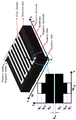
도 1a 및 도 1b를 참조하면, 레독스 흐름 전지(Redox Flow Battery, RFB)의 기본적인 구조는 전지 스택(출력)과 전해액 탱크(용량)가 분리할 수 있는 구조이다. 레독스 흐름 전지는 산화상태가 각각 다른 활물질이 저장되어 있는 탱크와 충전/방전시 활물질을 순환시키는 펌프, 및 이온교환막으로 분리되어 있는 셀을 포함한다. 활물질로는 V, Fe, Cr, Cu, Ti, Mn, 그리고 Sn 등의 전이금속을 강산 수용액에 용해하여 제조한 전해질을 사용한다. 제조한 전해질은 셀 내에 저장되어 있지 않고, 외부의 탱크에 액체 상태로 저장되어 있으며 충전/방전 과정 중에 펌프를 통하여 셀 내부로 공급된다. 또한 스택 내부에 사용하는 전극은 비활성 전극으로 전극 자체는 화학반응 없이 전극 표면과 전해질 사이에서 반응한다. 주요 레독스 커플은 Fe/Cr, V/V, V/Br, Zn/Br, Zn/Ce 등이 있다. 도 1c를 참조하면, 전해질은 3M H2SO4에 2M VOSO4를 용해시킨 용액을 사용하는 것이 일반적이며 이 경우 바나듐이온의 산화수는 +4이다.1A and 1B, a basic structure of a redox flow battery (RFB) is a structure in which a battery stack (output) and an electrolyte tank (capacity) can be separated. The redox flow battery includes a tank in which active materials having different oxidation states are stored, a pump for circulating active materials during charging/discharging, and a cell separated by an ion exchange membrane. As the active material, an electrolyte prepared by dissolving transition metals such as V, Fe, Cr, Cu, Ti, Mn, and Sn in a strong acid aqueous solution is used. The prepared electrolyte is not stored in the cell, but is stored in a liquid state in an external tank and is supplied into the cell through a pump during the filling/discharging process. Also, the electrode used inside the stack is an inert electrode, and the electrode itself reacts between the electrode surface and the electrolyte without chemical reaction. The main redox couples are Fe/Cr, V/V, V/Br, Zn/Br, and Zn/Ce. Referring to Figure 1c, the electrolyte is usually used a solution of 2M VOSO 4 dissolved in 3M H 2 SO 4 In this case, the oxidation number of the vanadium ion is +4.
스택 내부는 복수개의 전지 셀로 구성된다. 전지 셀은 이온 교환막인 멤브레인과, 멤브레인을 사이에 두고 위치하는 제1 및 제2 다공성 전극과, 제1 및 제2 다공성 전극의 가장자리에서 제1 및 제2 다공성 전극을 각각 고정시키는 제1 및 제2 플로우 프레임과, 제1 및 제2 다공성 전극의 외측에 각각 위치하는 양극 전극 및 음극 전극을 포함한다.The inside of the stack is composed of a plurality of battery cells. The battery cell includes a membrane which is an ion exchange membrane, first and second porous electrodes positioned with the membrane interposed therebetween, and first and second fixing electrodes of the first and second porous electrodes at the edges of the first and second porous electrodes, respectively. It includes a two flow frame and an anode electrode and a cathode electrode located outside the first and second porous electrodes, respectively.
제1 및 제2 다공성 전극은 카본 펠트로 제작될 수 있고, 양극 및 음극 전극은 그라파이트로 제작될 수 있다. 제1 및 제2 플로우 프레임에는 전해액 순환을 위한 복수의 홀을 포함한다.The first and second porous electrodes can be made of carbon felt, and the positive and negative electrodes can be made of graphite. The first and second flow frames include a plurality of holes for circulating electrolyte.
제1 플로우 프레임에서 복수의 홀 중 하나는 양극 전해액 주입구이고, 다른 하나는 양극 전해액 배출구이며, 나머지 두 개는 음극 전해액 통과공이다. 제1 플로우 프레임에는 양극 전해액 주입구와 제1 다공성 전극 사이 및 제1 다공성 전극과 양극 전해액 배출구 사이에 유로가 형성되어 제1 다공성 전극에 양극 전해액이 흐르도록 한다.In the first flow frame, one of the plurality of holes is an anode electrolyte inlet, the other is an anode electrolyte outlet, and the other two are cathode electrolyte pass holes. A flow path is formed in the first flow frame between the positive electrode electrolyte inlet and the first porous electrode and between the first porous electrode and the positive electrode electrolyte outlet so that the positive electrode electrolyte flows in the first porous electrode.
제2 플로우 프레임에서 복수의 홀 중 하나는 음극 전해액 주입구이고, 다른 하나는 음극 전해액 배출구이며, 나머지 두 개는 양극 전해액 통과공이다. 제2 플로우 프레임에는 음극 전해액 주입구와 제2 다공성 전극 사이 및 제2 다공성 전극과 음극 전해액 배출구 사이에 유로가 형성되어 제2 다공성 전극에 음극 전해액이 흐르도록 한다.In the second flow frame, one of the plurality of holes is a negative electrode electrolyte inlet, the other is a negative electrode electrolyte outlet, and the other two are positive electrode electrolyte through holes. A flow path is formed in the second flow frame between the negative electrode electrolyte inlet and the second porous electrode and between the second porous electrode and the negative electrode electrolyte outlet so that the negative electrode electrolyte flows in the second porous electrode.
양극 및 음극 전해액에 포함된 서로 다른 산화수를 가지는 두 종류의 레독스 커플(징크-브로민 또는 바나듐-바나듐 등)이 제1 및 제2 다공성 전극에서 반응함으로써 충전/방전이 이루어진다. 산화 반응에 의해 충전이 이루어지고, 환원 반응에 의해 방전이 이루어진다.Charging/discharging is performed by reacting two types of redox couples (such as zinc-bromine or vanadium-vanadium) having different oxidation numbers contained in the anode and cathode electrolytes at the first and second porous electrodes. Charging is performed by an oxidation reaction, and discharge is performed by a reduction reaction.
RFB에 적용 가능한 이온교환막은 이온의 선택 투과성이 높을 것, 전기적 저항이 작을 것, 용질 및 용매의 확산계수가 작을 것, 화학적으로 안정할 것과 같은 특성을 갖고 있어야 하며 Nafion과 CMV, AMV, DMV (Asahi Glass) 막이 널리 사용되고 있다. Microporous PVC separator와 ultra-microporous filter membrane, CMV, AMV 등에 전도성 고분자 인 polyaniline, polypyrrole 등을 접합시킨 막, Silica-filled PE, sulphonated polysulphone 막, PE 대칭막과 비대칭막에 전자선으로 가교한 막 등이 적용 가능하다.The ion-exchange membrane applicable to RFB must have properties such as high ion permeability, low electrical resistance, low solute and solvent diffusion coefficients, and chemical stability, such as Nafion, CMV, AMV, DMV ( Asahi Glass) films are widely used. Microporous PVC separator and ultra-microporous filter membrane, membranes in which conductive polymers such as polyaniline and polypyrrole are bonded to CMV, AMV, etc., Silica-filled PE, sulphonated polysulphone membranes, PE symmetric membranes and asymmetric membranes with electron beam crosslinking are applied. It is possible.
도 2a는 레독스 흐름 전지가 충전할 때 단위 셀의 전극 내부에서 반응물의 농도 분포를 예시한 도면이다. 도 2a는 Oh et al., Three-dimensional, transient, nonisothermal model of all-vanadium redox flow batteries, Energy, 81 (2015) 3-14에 도시된 도면이다.2A is a diagram illustrating the concentration distribution of reactants inside the electrode of the unit cell when the redox flow battery is charged. Figure 2a is a diagram shown in Oh et al., Three-dimensional, transient, nonisothermal model of all-vanadium redox flow batteries, Energy, 81 (2015) 3-14.
기존의 레독스 흐름 전지는 외부 탱크에서 매니폴드를 통해 셀(반응 전극)로 전해액이 전달될 때, 전극 내부의 전해액의 유량 분포와 농도 분포가 과전압에 영향을 미치고, 불균일한 분포는 전압 손실 및 부반응을 유발한다. 하지만 전극의 입구에서 유량과 농도가 일정하게 들어가더라도, 전극 내부는 반응이 진행됨에 따라 발생하는 과전압과 전극 내부의 농도 불균일을 해결하지 못한다.In the conventional redox flow battery, when the electrolyte is transferred from the outer tank through the manifold to the cell (reaction electrode), the flow rate distribution and concentration distribution of the electrolyte inside the electrode affect the overvoltage, and the uneven distribution causes voltage loss and Causes side reactions. However, even if the flow rate and concentration are constant at the inlet of the electrode, the inside of the electrode cannot solve the overvoltage and the uneven concentration inside the electrode as the reaction proceeds.
셀 구조에서 입구부로부터 출구부로 유동이 진행하면서 반응이 발생한다. 주 유동 방향과 전류 방향이 수직이기 때문에, 주 유동 방향 이외의 방향에도 활물질의 농도 편차가 필연적으로 발생한다. 확산 계수가 높은 물질을 사용하더라도 다공성 매질(Porous Medium) 내부에서는 확산 정도는 수학식 1의 Bruggeman correction에 의해 감소하게 된다.In the cell structure, the reaction proceeds as the flow proceeds from the inlet to the outlet. Since the main flow direction and the current direction are perpendicular, variations in concentration of the active material inevitably occur in directions other than the main flow direction. Even if a material having a high diffusion coefficient is used, the degree of diffusion in the porous medium is reduced by the Bruggeman correction of Equation 1.

D는 확산 계수이고, ε는 0 내지 1의 값을 갖는 공극률(Porosity)을 나타낸다. 즉, 기존의 레독스 흐름 전지는 반응 면적을 넓히기 위해 공극률을 줄이는데, 공극률의 감소에 따라 다공성 전극 내에서 확산 계수가 낮아지는 문제가 발생한다. 대면적화와 고 전류밀도를 진행하면 다공성 전극 내부의 농도 편차는 더욱 심해지게 된다.D is the diffusion coefficient, and ε represents the porosity having a value of 0 to 1. That is, the existing redox flow battery reduces the porosity in order to widen the reaction area, but the diffusion coefficient decreases in the porous electrode as the porosity decreases. If the large area and high current density are performed, the concentration variation inside the porous electrode becomes more severe.
본 실시예에서는 입구부에서 출구부로 흐르는 다공성 전극에 혼합판을 삽입하여 나누고, 혼합판 영역에서 농도 불균형을 개선한다. In this embodiment, the mixing plate is inserted into the porous electrode flowing from the inlet to the outlet, and the concentration imbalance in the region of the mixing plate is improved.
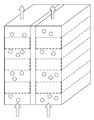
도 2b 및 도 2c는 레독스 흐름 전지가 적용 가능한 전극 구조를 예시한 도면이다. 도 2b는 Uncovering the role of flow rate in redox-active polymer flow batteries:simulation of reaction distributions with simultaneous mixing in tanks(Electrochimica Acta, 2017, Nemani et al)에 도시된 도면이고, 도 2c는 Numerical study on vanadium redox flow battery performance with nonuniformly compressed electrode and serpentine flow field(Applied Energy, 2018, Wang et al)에 도시된 도면이다.2B and 2C are diagrams illustrating an electrode structure to which a redox flow battery is applicable. Figure 2b is a diagram shown in Uncovering the role of flow rate in redox-active polymer flow batteries:simulation of reaction distributions with simultaneous mixing in tanks (Electrochimica Acta, 2017, Nemani et al), Figure 2c is a Numerical study on vanadium redox Flow battery performance with nonuniformly compressed electrode and serpentine flow field (Applied Energy, 2018, Wang et al).
일반적으로 레독스 흐름 전지 제작시 전극 한 단면 전체에 전해질 용액이 공급될 수 있고, 도 2b 및 도 2c와 같이 일부분에서 전해질 용액이 공급될 수도 있다. 일부분을 통해 공급되면 전극 내 전해질 농도 불균일한 정도가 커지므로, 본 실시예에 따른 레독스 흐름 전지의 효과가 커질 수 있다.In general, when manufacturing a redox flow battery, an electrolyte solution may be supplied to one entire electrode surface, and an electrolyte solution may be supplied in a part as shown in FIGS. 2B and 2C. When supplied through a part, since the degree of non-uniformity of the electrolyte concentration in the electrode increases, the effect of the redox flow battery according to this embodiment may increase.
도 3a 내지 도 3d는 레독스 흐름 전지의 구조를 예시한 도면이다. 레독스 흐름 전지는 이온 교환막(100) 및 전극부(200)를 포함한다. 제1 흐름 전극의 외측에 양극 전극이 위치하고, 제2 흐름 전극의 외측에 음극 전극이 위치할 수 있다. 레독스 흐름 전지는 제1 흐름 전극에서 유동하는 양극 전해액과 제2 흐름 전극에서 유동하는 음극 전해액을 각각 저장하는 두 개의 탱크를 포함할 수 있다. 레독스 흐름 전지는 양극 전해액과 음극 전해액을 각각 순환시키는 두 개의 펌프를 포함할 수 있다.3A to 3D are diagrams illustrating the structure of a redox flow battery. The redox flow battery includes an
전극부(200)는 이온 교환막(100)에 의해 분리된 제1 흐름 전극(210) 및 제2 흐름 전극(220)를 포함한다. 제1 흐름 전극(210)과 제2 흐름 전극(220)을 통하여 전해액이 유입 및 유출된다. 전극부에서 유동하는 전해액에 포함된 활물질이 산화 또는 환원 반응을 발생시켜, 전지는 충전/방전을 진행한다. The
제1 흐름 전극(210)과 제2 흐름 전극(220)은 다공성 매질로 구현된다.The
전극부(200)는 활물질이 이동하는 경로에 활물질을 혼합하는 혼합 공간을 형성한다. 혼합 공간(310, 320)은 제1 흐름 전극(210)과 제2 흐름 전극(220)에 각각 형성되어 활물질의 농도 편차를 감소시킨다.The
혼합 공간(310, 320)은 제1 흐름 전극(210) 및/또는 제2 흐름 전극(220)이 복수로 분리되고 이격 배치됨에 따라 형성된 빈 공간이다. 제1 혼합 공간(310)은 복수의 제1 흐름 전극 사이에 형성될 수 있다. 제2 혼합 공간(320)은 복수의 제2 흐름 전극 사이에 형성될 수 있다. The mixing
혼합 공간(310, 320)은 다공성 매질로 구현될 수 있다. 혼합 공간(310, 320)은 복수의 제1 흐름 전극(210) 및/또는 제2 흐름 전극(220) 사이에 형성되고, 혼합 공간의 공극률 또는 투수율은 제1 흐름 전극(210) 및/또는 제2 흐름 전극(220)의 공극률 또는 투수율보다 높은 값을 갖는다.The mixing
도 3b를 참조하면, 혼합 공간은 활물질의 이동 방향에 수직한 방향으로 길게 설치될 수 있다. 혼합 공간의 두께 및 폭은 제1 흐름 전극과 제2 흐름의 두께 및 폭보다 좁거나 동일할 수 있다.Referring to Figure 3b, the mixing space may be installed long in a direction perpendicular to the direction of movement of the active material. The thickness and width of the mixing space may be narrower or the same as the thickness and width of the first flow electrode and the second flow.
도 3c를 참조하면, 레독스 흐름 전지는 복수의 혼합판이 평행하게 설치된 구조로 형성될 수 있다.Referring to FIG. 3C, the redox flow battery may be formed in a structure in which a plurality of mixed plates are installed in parallel.
도 3d를 참조하면, 혼합판의 개념을 3차원 구조로 확장할 수 있다. 혼합 공간은 활물질의 이동 방향을 기준으로 기 설정된 각도로 길게 설치될 수 있다. 셀의 대면적화에 필연적으로 발생하는 농도 불균형을 해결하고, 과전압이나 부반응 발생을 최소화할 수 있다.Referring to FIG. 3D, the concept of a mixed plate can be extended to a three-dimensional structure. The mixing space may be installed at a predetermined angle based on the moving direction of the active material. It is possible to solve the concentration imbalance that inevitably occurs in the large area of the cell, and to minimize the occurrence of overvoltage or side reaction.
도 4a 내지 도 4d는 레독스 흐름 전지의 다공성 전극의 단면을 예시한 도면이다.4A to 4D are views illustrating a cross-section of a porous electrode of a redox flow battery.
도 4a는 일반 다공성 전극의 단면이고, 도 4b는 채널 중간에 형성된 혼합판 또는 혼합 공간을 갖는 다공성 전극의 단면이다. 도 4c 및 도 4d를 참조하면, 혼합 판 또는 혼합 공간의 폭은 외부에서 중심으로 갈수록 좁아지는 형상을 가질 수 있다. 4A is a cross section of a general porous electrode, and FIG. 4B is a cross section of a porous plate having a mixing plate or a mixing space formed in the middle of a channel. 4C and 4D, the width of the mixing plate or mixing space may have a shape that narrows toward the center from the outside.
전극부는 활물질의 이동 방향에 수직한 방향으로 돌출된 벽을 포함할 수 있고, 혼합판 또는 혼합 공간의 측면은 벽의 형상을 따라 함몰되는 구조를 갖는다. 혼합 공간의 측면은 삼각형, 삼각톱니, 사다리꼴, 반원, 이들의 조합으로 형성된 형상으로 함몰될 수 있다.The electrode portion may include a wall protruding in a direction perpendicular to the moving direction of the active material, and the side surface of the mixing plate or the mixing space has a structure that is recessed along the shape of the wall. The sides of the mixing space may be recessed into a shape formed by triangles, triangular teeth, trapezoids, semicircles, and combinations thereof.
도 5a 내지 도 5d는 레독스 흐름 전지의 다공성 전극에서 반응물의 농도 분포를 예시한 도면이다.5A to 5D are diagrams illustrating concentration distributions of reactants in a porous electrode of a redox flow battery.
도 5a는 일반 다공성 전극에서 바나듐 농도 등고선을 나타내고, 도 5b는 채널 중간에 형성된 혼합판 또는 혼합 공간을 갖는 다공성 전극에서 바나듐 농도 등고선을 나타낸다. 채널 형상이어도 농도 균일성이 증가한다. 도 5b에 도시된 혼합 공간보다 도 5c에 도시된 혼합 공간에서 혼합이 더 진행되고, 도 5c에 도시된 혼합 공간보다 도 5d에 도시된 혼합 공간에서 혼합이 더 진행된다. 혼합 공간의 함몰 깊이가 깊어질수록 혼합 공간에서 혼합 현상이 원활히 발생한다. 농도 균일성을 더 확보할 수 있고, 과전압이 감소하는 것을 파악할 수 있다.FIG. 5A shows a vanadium concentration contour line in a general porous electrode, and FIG. 5B shows a vanadium concentration contour line in a mixed plate formed in the middle of a channel or a porous electrode having a mixing space. Even in the form of a channel, the concentration uniformity increases. Mixing proceeds more in the mixing space shown in FIG. 5C than in the mixing space shown in FIG. 5B, and mixing proceeds more in the mixing space shown in FIG. 5D than in the mixing space shown in FIG. 5C. As the depth of depression of the mixing space increases, mixing phenomenon occurs smoothly in the mixing space. The concentration uniformity can be further secured, and it can be seen that the overvoltage decreases.
도 6 및 도 7은 본 발명의 실시예들에 따라 수행된 모의실험 결과를 도시한 것이다.6 and 7 show the simulation results performed according to the embodiments of the present invention.
정량적 분석을 위해 COMSOL Multiphysics package의 예제를 응용하여 2차원 단위 레독스 흐름 전지모델을 개발하고, 이를 통해 일반적인 레독스 흐름 전지 셀과 혼합판이 있는 전지의 특성을 비교하였다. 수치해석 모델은 160mA/cm2 일 때, 0.9 SOC(State of charge, 90%의 충전률)의 조건에서, 바나듐 레독스 흐름 전지를 기준으로 계산을 수행하였다. For quantitative analysis, the example of the COMSOL Multiphysics package was applied to develop a two-dimensional unit redox flow battery model, and through this, the characteristics of a typical redox flow battery cell and a battery with a mixed plate were compared. Numerical analysis model, 160mA / cm 2 , in the condition of 0.9 SOC (State of charge, 90% charge rate), the calculation was performed based on the vanadium redox flow battery.
도 6은 충전시 Cell voltage를 비교한 전위 결과를 도시하고 있다. 일반적인 단위 전지에 비하여 혼합판이 있는 혼합판 전극의 충전시 전위가 낮아짐을 확인할 수 있다. 저 SOC 영역에서는 0.2% 정도 낮아지는 것에 그치지만, 고 SOC 영역에서는 과전위를 3% 정도까지 낮출 수 있다. 현재 시뮬레이션의 경우 적당히 높은 유량과 작은 크기의 전지를 기준으로 수행했으나, 유량이 적어지거나 두께가 커지는 경우 이러한 효과는 커진다. 이를 통해 과전위를 감소시켜 에너지효율을 향상할 수 있으며, 같은 충전량일 때 전위를 낮춰서 정전용량(Capacitance)를 개선 시킬 수 있다. 이는 도 5b에 도시된 충전시 반응물의 농도 등고선(Contour)를 통해서 알 수 있다.6 shows potential results comparing cell voltage during charging. It can be seen that the potential is lowered when charging the mixed plate electrode with the mixed plate compared to the general unit cell. In the low SOC region, it is only about 0.2% lower, but in the high SOC region, the overpotential can be reduced to about 3%. In the current simulation, it was performed based on a moderately high flow rate and a small-sized battery, but this effect increases when the flow rate decreases or the thickness increases. Through this, energy efficiency can be improved by reducing the overpotential, and the potential can be lowered to improve the capacitance. This can be seen through the concentration contour of the reactants during filling shown in Figure 5b.
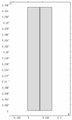
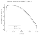
도 7a은 도 4d의 형상을 갖는 다공성 전극의 혼합 공간을 막 통과한 영역에서 X축에 따른 농도 분포를 도시한다. 이온 교환막에 가까울수록 농도가 내려가지만, 혼합 공간이 있는 다공성 전극에서 농도가 더 균일함을 파악할 수 있다. 농도 균일성은 다공성 전극의 혼합 공간을 통과하고 일정 거리를 이동한 위치에서도 파악할 수 있다. 다공성 전극의 끝단으로 갈수록 혼합판이 있는 경우에 농도 균일성이 더 높음을 파악할 수 있다.FIG. 7A shows the concentration distribution along the X axis in a region that has just passed through the mixing space of the porous electrode having the shape of FIG. 4D. The concentration decreases as it is closer to the ion exchange membrane, but it can be seen that the concentration is more uniform in the porous electrode with the mixed space. Concentration uniformity can be grasped even at a position that has passed a certain distance through the mixing space of the porous electrode. It can be seen that the concentration uniformity is higher in the presence of the mixed plate as it goes toward the end of the porous electrode.
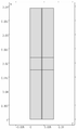
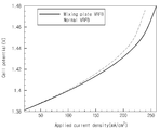
도 7b 및 도 7c는 작동 전류 조건에 따른 전지 전압(Cell Voltage)를 비교한 결과이다. 도 7b는 충전시 0.6 SOC, 유량 조건은 3 ml/s에서 작동 전류 조건에 따른 Cell voltage를 비교한 전위 결과이고, 도 7c는 충전시 0.9 SOC, 유량 조건은 5 ml/s에서 작동 전류 조건에 따른 Cell voltage를 비교한 전위 결과이다.7B and 7C are results of comparing cell voltages according to operating current conditions. Figure 7b is a potential result comparing the cell voltage according to the operating current conditions at 0.6 SOC, the flow rate is 3 ml / s when charging, Figure 7c is 0.9 SOC when charging, the flow condition is 5 ml / s at the operating current conditions It is the potential result comparing the cell voltages.
도 7b를 참조하면, 작동 전류 조건이 커질수록 셀의 전위차가 점점 커짐을 확인할 수 있다. 레독스 흐름 전지의 상용화를 위해서는 기존의 전류 밀도(40 ~ 160 mA/cm2) 보다 높은 전류 밀도에서 작동이 필수적인데, 본 실시예는 동일 SOC에서 2% 이상 전위가 낮아지는 것을 확인할 수 있다. 이는 동일 작동 조건에서 구조 변화만으로 4% 이상(충전시 2% 전위 감소, 방전시 2% 전위 증가) 에너지 효율이 상승한다는 의미이다. 에너지 효율은 수학식 2와 같이 표현된다.Referring to FIG. 7B, it can be seen that as the operating current condition increases, the potential difference of the cell gradually increases. In order to commercialize the redox flow battery, it is essential to operate at a current density higher than the existing current density (40 to 160 mA/cm 2 ), and it can be seen that this embodiment has a potential lower than 2% in the same SOC. This means that the energy efficiency is increased by more than 4% (2% potential decrease when charging, 2% potential increase when discharging) only by structural changes under the same operating conditions. The energy efficiency is expressed by

Vd는 방전시 전위이고, id는 방전시 전류이고, Vc는 충전시 전위이고, ic는 충전시 전류이다. 예컨대, 충전시 2% 전위 감소, 방전시 2% 전위 증가하는 것은 102/98 = 104%를 나타낸다.V d is the potential at discharge, i d is the current at discharge, V c is the potential at charge, and i c is the current at charge. For example, a 2% potential decrease upon charging and a 2% potential increase upon discharge indicate 102/98 = 104%.
도 7c를 통해 높은 SOC에서는 낮은 SOC보다 더 큰 차이가 발생함을 파악할 수 있다. 일반적으로 높은 SOC에서 전류 밀도를 상승시키면 급격히 Cell voltage가 상승하여 전지의 가용 용량(Capacity)을 감소시키는데, 혼합판을 도입한 레독스 흐름 전지에서는 상대적으로 완만한 Cell voltage 증가를 보이므로, 기존 전위보다 높은 가용 용량을 가질 것으로 기대할 수 있다.It can be seen through FIG. 7C that a larger difference occurs in a higher SOC than in a lower SOC. In general, when the current density is increased at a high SOC, the cell voltage rapidly increases to decrease the usable capacity (capacity) of the cell. In the redox flow battery incorporating a mixed plate, the relative voltage of the cell is relatively slow, so the existing potential It can be expected to have a higher available capacity.
본 실시예들은 본 실시예의 기술 사상을 설명하기 위한 것이고, 이러한 실시예에 의하여 본 실시예의 기술 사상의 범위가 한정되는 것은 아니다. 본 실시예의 보호 범위는 아래의 청구범위에 의하여 해석되어야 하며, 그와 동등한 범위 내에 있는 모든 기술 사상은 본 실시예의 권리범위에 포함되는 것으로 해석되어야 할 것이다.These embodiments are for explaining the technical spirit of the present embodiment, and the scope of the technical spirit of the present embodiment is not limited by these embodiments. The protection scope of the present embodiment should be interpreted by the claims below, and all technical spirits within the equivalent range should be interpreted as being included in the scope of the present embodiment.
100: 이온 교환막
200: 전극부
210: 제1 흐름 전극
220: 제2 흐름 전극
310, 320: 혼합 공간
410: 양극 전극
420: 음극 전극100: ion exchange membrane 200: electrode portion
210: first flow electrode 220: second flow electrode
310, 320: mixed space 410: anode electrode
420: cathode electrode
Claims (11)
상기 이온 교환막에 의해 분리된 제1 흐름 전극 및 제2 흐름 전극을 포함하며, 상기 제1 흐름 전극과 상기 제2 흐름 전극을 통하여 전해액이 유입 및 유출되며, 상기 전해액에 포함된 활물질이 산화 또는 환원 반응을 발생시키는 전극부를 포함하며,
상기 전극부는 상기 활물질이 이동하는 경로에 상기 활물질을 혼합하는 혼합 공간을 형성하는 것을 특징으로 하는 레독스 흐름 전지.Ion exchange membranes; And
It includes a first flow electrode and a second flow electrode separated by the ion exchange membrane, the electrolyte flows in and out through the first flow electrode and the second flow electrode, and the active material contained in the electrolyte is oxidized or reduced It includes an electrode portion for generating a reaction,
The electrode part forms a mixing space for mixing the active material in a path through which the active material moves.
상기 제1 흐름 전극과 상기 제2 흐름 전극은 다공성 매질로 구현되며,
상기 혼합 공간은 상기 제1 흐름 전극과 상기 제2 흐름 전극에 각각 형성되어 상기 활물질의 농도 편차를 감소시키는 것을 특징으로 하는 레독스 흐름 전지.According to claim 1,
The first flow electrode and the second flow electrode are implemented in a porous medium,
The mixing space is formed on each of the first flow electrode and the second flow electrode, thereby reducing the concentration variation of the active material, a redox flow battery.
상기 혼합 공간은,
상기 제1 흐름 전극 및/또는 상기 제2 흐름 전극이 복수로 분리되고 이격 배치됨에 따라 형성된 빈 공간으로, 상기 복수의 제1 흐름 전극 및/또는 제2 흐름 전극 사이에 형성되는 것을 특징으로 하는 레독스 흐름 전지.According to claim 1,
The mixing space,
The first flow electrode and / or the second flow electrode is a blank space formed as a plurality of separated and spaced apart, characterized in that formed between the plurality of first flow electrode and / or the second flow electrode Dox flow battery.
상기 제1 흐름 전극 및/또는 상기 제2 흐름 전극이 복수로 분리되고 이격 배치되고,
상기 혼합 공간은 다공성 매질로 구현되며, 상기 복수의 제1 흐름 전극 및/또는 제2 흐름 전극 사이에 형성되고, 상기 혼합 공간의 공극률 또는 투수율은 상기 제1 흐름 전극 및/또는 상기 제2 흐름 전극의 공극률 또는 투수율보다 높은 것을 특징으로 하는 레독스 흐름 전지.According to claim 1,
The plurality of first flow electrodes and/or the second flow electrodes are separated and spaced apart,
The mixing space is made of a porous medium, and is formed between the plurality of first flow electrodes and/or the second flow electrodes, and the porosity or permeability of the mixing space is the first flow electrode and/or the second flow electrode. Redox flow battery, characterized in that higher than the porosity or permeability of the.
상기 혼합 공간은 상기 활물질의 이동 방향에 수직한 방향으로 길게 설치되며, 상기 혼합 공간의 두께 및 폭은 상기 제1 흐름 전극과 상기 제2 흐름의 두께 및 폭보다 좁거나 동일한 것을 특징으로 하는 레독스 흐름 전지.According to claim 1,
The mixing space is installed long in a direction perpendicular to the direction of movement of the active material, and the thickness and width of the mixing space are narrower than or equal to the thickness and width of the first flow electrode and the second flow. Flow cell.
상기 혼합 공간은 상기 활물질의 이동 방향을 기준으로 기 설정된 각도로 길게 설치되며, 상기 혼합 공간의 두께 및 폭은 상기 제1 흐름 전극과 상기 제2 흐름의 두께 및 폭보다 좁거나 동일한 것을 특징으로 하는 레독스 흐름 전지.According to claim 1,
The mixing space is installed at a predetermined angle based on the moving direction of the active material, and the thickness and width of the mixing space are narrower or equal to the thickness and width of the first flow electrode and the second flow. Redox flow battery.
상기 혼합 공간의 폭은 외부에서 중심으로 갈수록 좁아지는 형상인 것을 특징으로 하는 레독스 흐름 전지.According to claim 1,
Redox flow battery, characterized in that the width of the mixing space is narrower from the outside toward the center.
상기 전극부는 상기 활물질의 이동 방향에 수직한 방향으로 돌출된 벽을 포함하며, 상기 혼합 공간의 측면은 상기 벽의 형상을 따라 함몰되는 것을 특징으로 하는 레독스 흐름 전지.According to claim 1,
The electrode portion includes a wall protruding in a direction perpendicular to the direction of movement of the active material, the side of the mixing space is redox flow battery, characterized in that recessed along the shape of the wall.
상기 혼합 공간의 측면은 삼각형, 삼각톱니, 사다리꼴, 반원, 이들의 조합으로 형성된 형상으로 함몰되는 것을 특징으로 하는 레독스 흐름 전지.The method of claim 8,
Redox flow battery characterized in that the side of the mixing space is recessed into a shape formed by a triangular, triangular cog, trapezoidal, semicircle, and combinations thereof.
상기 혼합 공간의 함몰 깊이가 깊어질수록 상기 혼합 공간에서 혼합 현상이 더 발생하는 것을 특징으로 하는 레독스 흐름 전지.The method of claim 8,
Redox flow battery, characterized in that the more deep the depression of the mixing space, the more the mixing phenomenon occurs in the mixing space.
상기 제1 흐름 전극의 외측에 양극 전극이 위치하고, 상기 제2 흐름 전극의 외측에 음극 전극이 위치하고,
상기 제1 흐름 전극에서 유동하는 양극 전해액과 상기 제2 흐름 전극에서 유동하는 음극 전해액을 각각 저장하는 두 개의 탱크를 포함하고,
상기 양극 전해액과 음극 전해액을 각각 순환시키는 두 개의 펌프를 포함하는 것을 특징으로 하는 레독스 흐름 전지.According to claim 1,
An anode electrode is positioned outside the first flow electrode, and a cathode electrode is positioned outside the second flow electrode,
And two tanks for storing the anode electrolyte flowing in the first flow electrode and the cathode electrolyte flowing in the second flow electrode, respectively.
Redox flow battery, characterized in that it comprises two pumps for circulating each of the positive electrode electrolyte and the negative electrode electrolyte.
Priority Applications (2)
| Application Number | Priority Date | Filing Date | Title |
|---|---|---|---|
| KR1020180154913A KR102144745B1 (en) | 2018-12-05 | 2018-12-05 | Redox Flow Battery with Porous Electrode in Which Mixing Plate Is Inserted |
| US16/276,380 US11069913B2 (en) | 2018-12-05 | 2019-02-14 | Redox flow battery with porous electrode in which mixing plate is inserted |
Applications Claiming Priority (1)
| Application Number | Priority Date | Filing Date | Title |
|---|---|---|---|
| KR1020180154913A KR102144745B1 (en) | 2018-12-05 | 2018-12-05 | Redox Flow Battery with Porous Electrode in Which Mixing Plate Is Inserted |
Publications (2)
| Publication Number | Publication Date |
|---|---|
| KR20200068213A true KR20200068213A (en) | 2020-06-15 |
| KR102144745B1 KR102144745B1 (en) | 2020-08-14 |
Family
ID=70970282
Family Applications (1)
| Application Number | Title | Priority Date | Filing Date |
|---|---|---|---|
| KR1020180154913A KR102144745B1 (en) | 2018-12-05 | 2018-12-05 | Redox Flow Battery with Porous Electrode in Which Mixing Plate Is Inserted |
Country Status (2)
| Country | Link |
|---|---|
| US (1) | US11069913B2 (en) |
| KR (1) | KR102144745B1 (en) |
Families Citing this family (3)
| Publication number | Priority date | Publication date | Assignee | Title |
|---|---|---|---|---|
| KR102549478B1 (en) | 2021-02-16 | 2023-06-29 | 연세대학교 산학협력단 | Simulation Apparatus and Method for Flow Battery having Porous Electrode with Flow Channel |
| KR102589318B1 (en) | 2021-05-27 | 2023-10-12 | 연세대학교 산학협력단 | Vanadium Redox flow battery for data center and operating method thereof |
| KR102559887B1 (en) * | 2021-05-31 | 2023-07-26 | 동국대학교 산학협력단 | Redox flow battery electrolyte storage tank for electric propulsion system and redox flow battery device having the same |
Citations (6)
| Publication number | Priority date | Publication date | Assignee | Title |
|---|---|---|---|---|
| JPH08287923A (en) * | 1995-04-13 | 1996-11-01 | Toyobo Co Ltd | Electrode material for flowing liquid electrolytic cell |
| JP2003157885A (en) * | 2001-11-21 | 2003-05-30 | Sumitomo Electric Ind Ltd | Electrode for redox flow battery and redox flow battery |
| KR20110088881A (en) | 2010-01-29 | 2011-08-04 | 삼성전자주식회사 | Redox flow battery |
| JP2018010804A (en) * | 2016-07-14 | 2018-01-18 | 京セラ株式会社 | Flow battery |
| KR20180036391A (en) * | 2016-09-30 | 2018-04-09 | 롯데케미칼 주식회사 | Method for controlling operation of redox flow battery |
| JP2018186014A (en) * | 2017-04-26 | 2018-11-22 | 日立化成株式会社 | Flow battery, flow battery system, and power generation system |
Family Cites Families (7)
| Publication number | Priority date | Publication date | Assignee | Title |
|---|---|---|---|---|
| JPS608224B2 (en) | 1980-05-29 | 1985-03-01 | 花王株式会社 | porous sheet |
| WO2013095378A1 (en) * | 2011-12-20 | 2013-06-27 | United Technologies Corporation | Flow battery with mixed flow |
| KR101443680B1 (en) * | 2012-02-09 | 2014-09-26 | 전자부품연구원 | Redox flow secondary cell |
| JP6400410B2 (en) | 2014-09-25 | 2018-10-03 | 国立大学法人横浜国立大学 | Electrolysis cell for organic chemical hydride production |
| CN106471658B (en) | 2015-04-14 | 2019-03-15 | 住友电气工业株式会社 | Frame body, unit framework and redox flow batteries for redox flow batteries |
| EP3306727A4 (en) * | 2015-05-27 | 2018-05-23 | Sumitomo Electric Industries, Ltd. | Redox flow battery |
| JP6660272B2 (en) | 2016-08-30 | 2020-03-11 | 株式会社沖データ | Fixing device and image forming device |
-
2018
- 2018-12-05 KR KR1020180154913A patent/KR102144745B1/en active IP Right Grant
-
2019
- 2019-02-14 US US16/276,380 patent/US11069913B2/en active Active
Patent Citations (6)
| Publication number | Priority date | Publication date | Assignee | Title |
|---|---|---|---|---|
| JPH08287923A (en) * | 1995-04-13 | 1996-11-01 | Toyobo Co Ltd | Electrode material for flowing liquid electrolytic cell |
| JP2003157885A (en) * | 2001-11-21 | 2003-05-30 | Sumitomo Electric Ind Ltd | Electrode for redox flow battery and redox flow battery |
| KR20110088881A (en) | 2010-01-29 | 2011-08-04 | 삼성전자주식회사 | Redox flow battery |
| JP2018010804A (en) * | 2016-07-14 | 2018-01-18 | 京セラ株式会社 | Flow battery |
| KR20180036391A (en) * | 2016-09-30 | 2018-04-09 | 롯데케미칼 주식회사 | Method for controlling operation of redox flow battery |
| JP2018186014A (en) * | 2017-04-26 | 2018-11-22 | 日立化成株式会社 | Flow battery, flow battery system, and power generation system |
Also Published As
| Publication number | Publication date |
|---|---|
| KR102144745B1 (en) | 2020-08-14 |
| US11069913B2 (en) | 2021-07-20 |
| US20200185748A1 (en) | 2020-06-11 |
Similar Documents
| Publication | Publication Date | Title |
|---|---|---|
| EP3346537B1 (en) | Bipolar plate, cell frame and cell stack, and redox flow battery | |
| US10218007B2 (en) | Bipolar plate, redox flow battery, and method for producing bipolar plate | |
| US9680172B2 (en) | Flow-type electrochemical cell | |
| US10593964B2 (en) | Bipolar plate, cell frame, cell stack and redox-flow battery | |
| EP3306727A1 (en) | Redox flow battery | |
| US20100003586A1 (en) | Redox flow cell | |
| KR102144745B1 (en) | Redox Flow Battery with Porous Electrode in Which Mixing Plate Is Inserted | |
| JPH1012261A (en) | Redox flow battery | |
| KR20090046087A (en) | A separator structure and redox flow battery containing the separator membrane | |
| JP2014130778A (en) | Stationary vanadium redox battery | |
| EP3565048A1 (en) | Redox flow battery | |
| KR20130106530A (en) | Flow battery using the metallocene | |
| EP3579250B1 (en) | Polymer electrolyte membrane, electrochemical cell and flow cell each comprising same, composition for polymer electrolyte membrane, and method for preparing polymer electrolyte membrane | |
| EP4136694A1 (en) | Redox flow battery with immiscible electrolyte and flow through electrode | |
| US20160226118A1 (en) | Sodium-based hybrid flow batteries with ultrahigh energy densities | |
| KR20200055311A (en) | Manifold with back side flow path and Redox flow battery | |
| US11309567B2 (en) | Ion exchange membrane and flow battery including same | |
| JP2001216995A (en) | Electrolyte tank for redox flow battery | |
| KR20200055274A (en) | Bipolar plate and unit cell for redox flow cell battery and redox flow battery comprising the same | |
| CN116706183B (en) | Pile, bipolar plate and electrode frame of flow battery | |
| US20220407102A1 (en) | Zinc-bromine flow battery including conductive interlayer | |
| TW202414875A (en) | Redox flow battery and electrolyte thereof | |
| KR20170056941A (en) | Anion exchange membrane used for highly-durable redox flow battery having low ion permeablility for vanadium ion and redox flow battery including the same | |
| Albertus | RANGE concepts beyond the RANGE program | |
| JPH0287483A (en) | Separator of zinc-bromine cell |
Legal Events
| Date | Code | Title | Description |
|---|---|---|---|
| E701 | Decision to grant or registration of patent right | ||
| GRNT | Written decision to grant |