KR20200065493A - Partial discharge reduction device for distribution line - Google Patents
Partial discharge reduction device for distribution line Download PDFInfo
- Publication number
- KR20200065493A KR20200065493A KR1020180152019A KR20180152019A KR20200065493A KR 20200065493 A KR20200065493 A KR 20200065493A KR 1020180152019 A KR1020180152019 A KR 1020180152019A KR 20180152019 A KR20180152019 A KR 20180152019A KR 20200065493 A KR20200065493 A KR 20200065493A
- Authority
- KR
- South Korea
- Prior art keywords
- electric field
- partial discharge
- conductor
- current
- distribution line
- Prior art date
Links
Images


Classifications
-
- H—ELECTRICITY
- H02—GENERATION; CONVERSION OR DISTRIBUTION OF ELECTRIC POWER
- H02G—INSTALLATION OF ELECTRIC CABLES OR LINES, OR OF COMBINED OPTICAL AND ELECTRIC CABLES OR LINES
- H02G15/00—Cable fittings
- H02G15/08—Cable junctions
-
- H—ELECTRICITY
- H02—GENERATION; CONVERSION OR DISTRIBUTION OF ELECTRIC POWER
- H02G—INSTALLATION OF ELECTRIC CABLES OR LINES, OR OF COMBINED OPTICAL AND ELECTRIC CABLES OR LINES
- H02G15/00—Cable fittings
- H02G15/08—Cable junctions
- H02G15/18—Cable junctions protected by sleeves, e.g. for communication cable
- H02G15/196—Cable junctions protected by sleeves, e.g. for communication cable having lapped insulation
Landscapes
- Testing Relating To Insulation (AREA)
Abstract
Description
본 발명은 배전선로용 부분방전 저감장치에 관한 것으로서, 더욱 상세하게는 고주파제거부가 도체부에 공급되는 고주파 성분의 신호 전류를 제거하고, 전계완화부가 도체부에서 발생하는 전계를 완화시킴으로써, 배전선로에 설치된 전력설비의 부분방전 진단시 정확도를 향상시키는 배전선로용 부분방전 저감장치에 관한 것이다.The present invention relates to a partial discharge reduction device for a distribution line, and more specifically, by removing the signal current of the high-frequency component supplied to the conductor portion of the high-frequency elimination unit, and the electric field relaxation unit to relieve the electric field generated in the conductor portion, the distribution line It relates to a partial discharge reduction device for a distribution line that improves the accuracy in the diagnosis of the partial discharge of power facilities installed in.
일반적으로 부분방전은 각종 산업체 및 전력계통 변전소에 설치되는 고압 배전반, 고압 케이블, 변압기, GIS(Gas Insulated Switchgear, 가스절연 개폐장치), 개폐기, 수전설비 등 전력기기 시스템의 어느 한 부분에 생기는 방전을 총칭하는 것으로서, 전극의 첨단 부근에 생기는 코로나 현상 및 절연물의 표면을 따라서 생기는 연면방전, 절연물 내의 공극에 생기는 보이드 방전 등이 있다.In general, partial discharge is a discharge generated in any part of the power equipment system such as high-voltage switchboards, high-voltage cables, transformers, gas insulated switchgear (GIS), switchgear, and power receiving equipment installed in various industries and power system substations. As general terms, there are corona phenomena occurring near the tip of the electrode, creeping discharges along the surface of the insulator, and void discharges in voids in the insulator.
전력기기의 이상 유무 감지 및 절연체의 열화 정도를 감시하고 수리시기를 예측하는 것은 매우 중요하며, 부분방전의 측정 및 감시로 이러한 예측과 관리가 가능하다. 이러한 목적으로 고압 케이블, 변압기, GIS(Gas Insulated Switchgear, 가스절연 개폐장치), 개폐기, 수전설비, 고압반, 저압반, 모터제어반, 배전반 등의 다양한 전력설비에서 부분방전 측정 장치들이 사용되고 있다.It is very important to detect the presence of abnormality in the power equipment, monitor the degree of deterioration of the insulator, and predict the repair time, and this prediction and management is possible by measuring and monitoring the partial discharge. For this purpose, partial discharge measurement devices are used in various power facilities such as high voltage cables, transformers, gas insulated switchgear (GIS), switchgear, power receiving equipment, high voltage panels, low voltage panels, motor control panels, and distribution panels.
이와 같은 전력설비에는 고전압상황에서 발생하는 방전현상을 방지하기 위해서 여러 종류의 절연물이 사용되고 있는데, 이러한 절연물은 공극 또는 박리 등과 같은 갭(gap)이 제조공정 중에 어떤 이유나 동작 중의 냉각 및 가열 과정에서 발생할 수 있다. Various types of insulating materials are used in such power facilities to prevent the discharge phenomenon occurring in a high voltage situation. Such insulating materials may cause gaps such as voids or peeling during any manufacturing process or during cooling and heating during operation. Can be.
그러나 이러한 갭은 높은 전계가 인가될 때마다 부분방전을 발생하게 되고, 부분 방전이 반복되면 절연물이 서서히 침식되면서 절연 내력(dielectricstrength)을 감소시킴으로써, 결국 심각한 절연 파괴 사고가 발생하게 된다.However, such a gap generates a partial discharge whenever a high electric field is applied, and when the partial discharge is repeated, the insulation gradually erodes and the dielectric strength is reduced, resulting in a serious dielectric breakdown accident.
특히, 전력설비 중 변압기의 경우 수배전 설비의 중요한 전력설비이면서 부분방전이 발생할 확률이 매우 높은 조건을 가지고 있을 뿐만 아니라, 부분방전이 전달되는 거리와 범위도 넓어지는 특징을 가짐으로 인해 부분방전 진단시 다른 전력설비에서 발생된 부분방전이 섞인 전하량이 검출됨으로써, 진단 신뢰성이 떨어지는 문제점이 있다.Particularly, in the case of a transformer among power facilities, it is an important power facility of a water distribution facility and has a very high probability of partial discharge, and also has a feature that the distance and range in which the partial discharge is transmitted are widened. There is a problem in that the reliability of diagnosis is deteriorated by detecting the amount of charge mixed with partial discharges generated at other power facilities.
따라서, 이를 해결할 필요성이 요청된다.Therefore, there is a need to solve this.
관련 배경기술로는, 대한민국 등록특허공보 제10-0915633호(2009.08.28. 등록, 명칭: 고주파 잡음 신호 변화량 비교에 의한 가공 배전 선로불량설비 검출 장치 및 방법)가 있다.As a related background technology, there is a Republic of Korea Patent Publication No. 10-0915633 (August 28, 2009, registered, name: a device and method for detecting a defective line in a power distribution line by comparing the amount of change in a high-frequency noise signal).
본 발명은 상기와 같은 필요성에 의해 창출된 것으로서, 고주파제거부가 도체부에 공급되는 고주파 성분의 전류를 제거하고, 전계완화부가 도체부에서 발생하는 전계를 완화시킴으로써, 배전선로에 설치된 전력설비의 부분방전 진단시 정확도를 향상시키는 배전선로용 부분방전 저감장치에 관한 것이다.The present invention was created by the necessity as described above, and the high-frequency elimination part removes the current of the high-frequency component supplied to the conductor part, and the electric field relaxation part relieves the electric field generated in the conductor part, so that the part of the power facility installed in the distribution line. It relates to a partial discharge reduction device for a distribution line that improves the accuracy in the diagnosis of discharge.
상기한 목적을 달성하기 위하여 본 발명의 일 실시예에 따른 배전선로용 부분방전 저감장치는 가공선로와 지중선로가 연결되는 부위에 설치되는 도체부와, 상기 도체부의 둘레면에 구비되어 상기 도체부에 공급되는 고주파 성분의 전류를 제거하는 고주파제거부 및 상기 고주파제거부를 수용하도록 상기 도체부에 통전 가능하게 지지되어 상기 도체부에 전류 공급시 전계를 완화시키는 전계완화케이스를 포함하는 것을 특징으로 한다.In order to achieve the above object, the partial discharge reduction device for a distribution line according to an embodiment of the present invention is provided on a conductor portion installed in a portion where the overhead line and the underground line are connected, and the conductor portion is provided on the circumferential surface of the conductor portion It characterized in that it comprises a high-frequency elimination unit for removing the current of the high-frequency component supplied to the electric field relaxation case to be energized to be supported on the conductor portion to accommodate the high-frequency removal unit to relieve the electric field when the current is supplied to the conductor portion. .
상기 고주파제거부는 상기 도체부에 전류가 통과시 500㎑ 내지 100㎒의 주파수 대역을 차단하는 페라이트 코어일 수 있다.The high-frequency removing unit may be a ferrite core that blocks a frequency band of 500 kHz to 100 MHz when current passes through the conductor.
상기 전계완화케이스는 상기 도체부에 전류 공급시 전달방지부에 의해 배선전로에서 수용가로 부분방전의 전달이 방지될 수 있다.In the electric field relaxation case, when the current is supplied to the conductor, the transmission of the partial discharge from the wiring converter to the consumer can be prevented by the transmission preventing unit.
상기 전달방지부는 상기 전계완화케이스가 상기 도체부에 고주파 성분이 제거된 전류와 통전되도록 상기 전계완화케이스에 형성되는 이격홀부 및 상기 도체부가 통과되도록 상기 이격홀부에 안착 가능하게 삽입되어 전류를 차단하는 절연캡을 포함한다.The transmission preventing portion is inserted into the separation hole portion so as to pass through the separation hole portion formed in the electric field relaxation case and the conductor portion so that the electric field relaxation case is energized with the current from which the high-frequency component is removed from the conductor portion to block current. Includes insulating cap.
상기 전계완화케이스는 상기 도체부에서 전계를 발생시 전계가 집중되는 현상이 방지되도록 모서리 부위에 라운드지게 형성되는 전계집중방지부를 구비할 수 있다.The electric field alleviation case may include an electric field concentration preventing portion that is formed to be rounded at a corner to prevent the electric field from being concentrated when an electric field is generated in the conductor portion.
본 발명에 따른 배전선로용 부분방전 저감장치는 고주파제거부가 도체부에 공급되는 고주파 성분의 신호 전류를 제거하고, 전계완화부가 도체부에서 발생하는 전계를 완화시키는 구조를 가짐에 따라 배전선로에 설치된 전력설비의 부분방전 진단시 정확도가 향상되어 불량설비에 대한 색출작업이 용이할 뿐만 아니라, 이로 인해 배전선로의 정전 현상을 예방할 수 있는 효과를 가진다.The partial discharge reduction device for a distribution line according to the present invention is installed in the distribution line as the high frequency elimination part removes the signal current of the high frequency component supplied to the conductor part, and the electric field relaxation part has a structure to relieve the electric field generated in the conductor part. The accuracy in diagnosing the partial discharge of power facilities is improved, so it is easy to find out the defective equipment, and this has the effect of preventing the power failure of the distribution line.
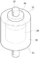
도 1은 본 발명의 일 실시예에 따른 배전선로용 부분방전 저감장치를 도시한 사시도이다.
도 2는 본 발명의 일 실시예에 따른 배전선로용 부분방전 저감장치를 도시한 분해 사시도이다.
도 3은 본 발명의 일 실시예에 따른 배전선로용 부분방전 저감장치를 도시한 단면도이다.1 is a perspective view showing a partial discharge reduction device for a distribution line according to an embodiment of the present invention.
2 is an exploded perspective view showing a partial discharge reduction device for a distribution line according to an embodiment of the present invention.
3 is a cross-sectional view showing a partial discharge reduction device for a distribution line according to an embodiment of the present invention.
이하, 첨부된 도면들을 참조하여 본 발명에 따른 배전선로용 개폐기의 부분방전 저감장치를 설명하도록 한다.Hereinafter, a partial discharge reduction device of a switch for a distribution line according to the present invention will be described with reference to the accompanying drawings.
이 과정에서 도면에 도시된 선들의 두께나 구성요소의 크기 등은 설명의 명료성과 편의상 과장되게 도시되어 있을 수 있다. 또한, 후술되는 용어들은 본 발명에서의 기능을 고려하여 정의된 용어들로서 이는 사용자, 운용자의 의도 또는 관례에 따라 달라질 수 있다. 그러므로 이러한 용어들에 대한 정의는 본 명세서 전반에 걸친 내용을 토대로 내려져야 할 것이다.In this process, the thickness of the lines or the size of components shown in the drawings may be exaggerated for clarity and convenience. In addition, terms to be described later are terms defined in consideration of functions in the present invention, which may vary according to a user's or operator's intention or practice. Therefore, the definition of these terms should be made based on the contents throughout the specification.
도 1은 본 발명의 일 실시예에 따른 배전선로용 부분방전 저감장치를 도시한 사시도이고, 도 2는 본 발명의 일 실시예에 따른 배전선로용 부분방전 저감장치를 도시한 분해 사시도이며, 도 3은 본 발명의 일 실시예에 따른 배전선로용 부분방전 저감장치를 도시한 단면도이다.1 is a perspective view showing a partial discharge reduction device for a distribution line according to an embodiment of the present invention, Figure 2 is an exploded perspective view showing a partial discharge reduction device for a distribution line according to an embodiment of the present invention, 3 is a cross-sectional view showing a partial discharge reduction device for a distribution line according to an embodiment of the present invention.
본 발명의 일 실시예에 따른 배전선로용 부분방전 저감장치는 도 1 내지 도 3에서 도시된 바와 같이 도체부(10), 고주파제거부(20) 및 전계완화케이스(30)를 포함한다.A partial discharge reduction device for a distribution line according to an embodiment of the present invention includes a
도체부(10)는 가공선로와 지중선로가 연결되는 부위에 설치된다. 이러한 도체부(10)는 배전선로에서 수용가로 전기 에너지를 공급시 전류가 이동하는 경로를 제공하는 역할을 수행할 뿐만 아니라, 고주파제거부(20) 및 전계완화케이스(30)가 설치되는 공간을 제공하는 역할을 수행한다.The
그리고, 고주파제거부(20)는 도체부(10)의 둘레면에 구비되어 도체부(10)에 공급되는 고주파 성분의 전류를 제거한다. 이러한 고주파제거부(20)는 도체부(10)에 끼워진 형태로 배치되어 도체부(10)에 수용가로 공급되는 전류가 흐르면 유효한 신호 전류는 손실없이 원활하게 통과시키며, 해로운 고주파 신호 전류는 소모시키는 역할을 수행한다. Then, the high-
이에 따라, 배전선로에 설치된 설비의 부분방전 진단시 다른 전력설비에서 발생되는 부분방전이 섞여서 전하량 검출되는 오류를 방지할 수 있어 진단 정확도를 향상시킬 뿐만 아니라, 이로 인해 불량설비의 색출이 용이하여 배전선로의 정전 현상을 예방할 수 있게 된다.Accordingly, when a partial discharge diagnosis of a facility installed in a distribution line is diagnosed, partial discharges generated from other power facilities can be mixed to prevent an error in detecting the amount of charge, thereby improving the accuracy of diagnosis and thereby facilitating the detection of defective facilities. It is possible to prevent a power failure phenomenon of the furnace.
이를 위해, 고주파제거부(20)는 도체부(10)에 전류가 통과시 500㎑ 내지 100㎒의 주파수 대역을 차단하는 페라이트 코어인 것으로 한다. 이러한 페라이트 코어는 산화철과 산화 아연ㆍ산화 망간ㆍ산화 니켈 등을 혼합해서 소결한 자성체를 소재로 한 자심(磁心) 절연물로서, μ(투자율)가 크고 품질계수가 높은 것이 특징이다.To this end, it is assumed that the high-
즉, 페라이트 코어는 도체부(10)에 500㎑ 내지 100㎒의 주파수를 가진 신호가 통과할 때 신호 크기를 많이 감쇄시키고, 대역 선택도가 높아 대역폭이 좁으므로, 500㎑ 이하의 주파수 신호들은 원활하게 통과시키고, 500㎑ 내지 100㎒ 이하의 주파수 신호는 차단하는 특성을 보이게 된다.That is, the ferrite core attenuates the signal size a lot when a signal having a frequency of 500 kHz to 100 MHz passes through the
한편, 전계완화케이스(30)는 고주파제거부(20)를 수용하도록 도체부(10)에 통전 가능하게 지지되어 도체부(10)에 전류 공급시 전계를 완화시킨다. On the other hand, the electric
이러한 전계완화케이스(30)는 원통 형상으로 형성되어 고주파제거부(20)를 통해 고주파가 제거된 전류를 도체부(10)로부터 공급받도록 일측이 도체부(10)에 접하도록 지지된다. The electric
이때, 전계완화케이스(30)는 도체부(10)에서 전계를 발생시 전계가 모서리 부위로 집중되는 현상이 방지되도록 모서리 부위에 라운드지게 형성되는 전계집중방지부(31)를 구비한다. 이에 따라, 본 발명에 따른 배전선로용 부분방전 저감장치를 설치하는 과정에서 코로나 현상 또는 절연파괴로 인한 선로 고장을 방지할 수 있게 된다.At this time, the electric
또한, 전계완화케이스(30)는 도체부(10)에 전류 공급시 전달방지부(40)에 의해 배선전로에서 수용가로 부분방전의 전달이 방지될 수 있다. 구체적으로, 전달방지부(40)는 전계완화케이스(30)가 도체부(10)에 고주파 성분이 제거된 전류와 통전되도록 전계완화케이스(30)의 타측에 형성되는 이격홀부(41) 및 도체부(10)가 통과되도록 이격홀부(41)에 안착 가능하게 삽입되어 전류를 차단하는 절연캡(42)을 포함한다. In addition, the electric
이로써, 전계완화케이스(30)는 타측이 도체부(10)에 접촉되는 현상이 원천적으로 봉쇄됨으로써, 도체부(10)에 전류 공급시 고주파제거부(20)를 거치지 않고 수용가로 공급되는 현상을 방지할 수 있게 된다.Thus, the electric
본 발명은 도면에 도시된 실시예를 참고로 하여 설명되었으나, 이는 예시적인 것에 불과하며, 당해 기술이 속하는 분야에서 통상의 지식을 가진 자라면 이로부터 다양한 변형 및 균등한 타 실시예가 가능하다는 점을 이해할 것이다.The present invention has been described with reference to the embodiment shown in the drawings, but this is only exemplary, and those skilled in the art to which the art belongs can various modifications and equivalent other embodiments from this. Will understand.
따라서, 본 발명의 진정한 기술적 보호범위는 아래의 특허청구범위에 의해서 정하여져야 할 것이다.Therefore, the true technical protection scope of the present invention should be defined by the claims below.
10: 도체부
20: 고주파차단부
30: 전계완화케이스
31: 전계집중방지부
40: 전달방지부
41: 이격홀부
42: 절연캡10: conductor
20: high-frequency cut-off
30: electric field relaxation case
31: electric field concentration prevention unit
40: transmission prevention unit
41: separation hole
42: insulating cap
Claims (5)
상기 도체부의 둘레면을 감싸도록 구비되어 상기 도체부에 공급되는 고주파 성분의 전류를 제거하는 고주파제거부; 및
상기 고주파제거부를 수용하도록 상기 도체부에 통전 가능하게 지지되어 상기 도체부에 전류 공급시 전계를 완화시키는 전계완화케이스;
를 포함하는 것을 특징으로 하는 배전선로용 부분방전 저감장치.
A conductor part installed at a portion where the overhead line and the underground line are connected;
A high frequency removing unit provided to surround the circumferential surface of the conductor portion to remove current of high frequency components supplied to the conductor portion; And
An electric field relaxation case which is electrically supported on the conductor portion to accommodate the high-frequency removing portion to relieve an electric field when current is supplied to the conductor portion;
Partial discharge reduction device for a distribution line comprising a.
상기 고주파제거부는 상기 도체부에 전류가 통과시 500㎑ 내지 100㎒의 주파수 대역을 차단하는 페라이트 코어인 것을 특징으로 하는 배전선로용 부분방전 저감장치.
According to claim 1,
The high-frequency removing unit is a partial discharge reduction device for a distribution line, characterized in that the ferrite core to cut off the frequency band of 500 ㎑ to 100 ㎒ when current passes through the conductor.
상기 전계완화케이스는 상기 도체부에 전류 공급시 전달방지부에 의해 배선전로에서 수용가로 부분방전의 전달이 방지되는 것을 특징으로 하는 배전선로용 부분방전 저감장치.
According to claim 1,
The electric field relaxation case is a partial discharge reduction device for a distribution line, characterized in that the transmission of the partial discharge from the wiring line to the consumer by the transmission preventing portion when the current is supplied to the conductor.
상기 전달방지부는,
상기 전계완화케이스가 상기 도체부에 고주파 성분이 제거된 전류와 통전되도록 상기 전계완화케이스에 형성되는 이격홀부; 및
상기 도체부가 통과되도록 상기 이격홀부에 안착 가능하게 삽입되어 전류를 차단하는 절연캡;
을 포함하는 것을 특징으로 하는 배전선로용 부분방전 저감장치.
According to claim 3,
The transfer prevention unit,
A separation hole formed in the electric field relaxation case so that the electric field relaxation case is energized with the current from which the high frequency component is removed from the conductor portion; And
An insulating cap that is securely inserted into the separation hole portion so as to pass through the conductor portion to block current;
Partial discharge reduction device for a distribution line comprising a.
상기 전계완화케이스는 상기 도체부에서 전계를 발생시 전계가 집중되는 현상이 방지되도록 모서리 부위에 라운드지게 형성되는 전계집중방지부를 구비하는 것을 특징으로 하는 배전선로용 부분방전 저감장치.According to claim 1,
The electric field alleviation case is a partial discharge reduction device for a distribution line, characterized in that it has an electric field concentration prevention portion that is formed round in the corner to prevent the phenomenon that the electric field is concentrated when the electric field is generated in the conductor portion.
Priority Applications (1)
| Application Number | Priority Date | Filing Date | Title |
|---|---|---|---|
| KR1020180152019A KR102178394B1 (en) | 2018-11-30 | 2018-11-30 | Partial discharge reduction device for distribution line |
Applications Claiming Priority (1)
| Application Number | Priority Date | Filing Date | Title |
|---|---|---|---|
| KR1020180152019A KR102178394B1 (en) | 2018-11-30 | 2018-11-30 | Partial discharge reduction device for distribution line |
Publications (2)
| Publication Number | Publication Date |
|---|---|
| KR20200065493A true KR20200065493A (en) | 2020-06-09 |
| KR102178394B1 KR102178394B1 (en) | 2020-11-13 |
Family
ID=71082042
Family Applications (1)
| Application Number | Title | Priority Date | Filing Date |
|---|---|---|---|
| KR1020180152019A KR102178394B1 (en) | 2018-11-30 | 2018-11-30 | Partial discharge reduction device for distribution line |
Country Status (1)
| Country | Link |
|---|---|
| KR (1) | KR102178394B1 (en) |
Citations (4)
| Publication number | Priority date | Publication date | Assignee | Title |
|---|---|---|---|---|
| JPH10123201A (en) * | 1996-10-16 | 1998-05-15 | Fujikura Ltd | Sensitivity improving structure of partial-discharge measuring device |
| JPH10341519A (en) * | 1997-06-06 | 1998-12-22 | Toshiba Corp | Partial discharging detection electrode for gas isolation opening and closing device |
| KR20090075294A (en) * | 2008-01-04 | 2009-07-08 | 엘지전자 주식회사 | Emi filter for cable |
| JP2015045590A (en) * | 2013-08-29 | 2015-03-12 | T&A株式会社 | Device and method for measuring electromagnetic wave loss using electromagnetic wave absorption layer |
-
2018
- 2018-11-30 KR KR1020180152019A patent/KR102178394B1/en active IP Right Grant
Patent Citations (4)
| Publication number | Priority date | Publication date | Assignee | Title |
|---|---|---|---|---|
| JPH10123201A (en) * | 1996-10-16 | 1998-05-15 | Fujikura Ltd | Sensitivity improving structure of partial-discharge measuring device |
| JPH10341519A (en) * | 1997-06-06 | 1998-12-22 | Toshiba Corp | Partial discharging detection electrode for gas isolation opening and closing device |
| KR20090075294A (en) * | 2008-01-04 | 2009-07-08 | 엘지전자 주식회사 | Emi filter for cable |
| JP2015045590A (en) * | 2013-08-29 | 2015-03-12 | T&A株式会社 | Device and method for measuring electromagnetic wave loss using electromagnetic wave absorption layer |
Also Published As
| Publication number | Publication date |
|---|---|
| KR102178394B1 (en) | 2020-11-13 |
Similar Documents
| Publication | Publication Date | Title |
|---|---|---|
| WO2010023830A1 (en) | Gas-insulated device | |
| CN107957529B (en) | Method and apparatus for testing current connections of a high voltage condenser bushing assembly | |
| US10161987B2 (en) | Insulation degradation monitoring device | |
| JP5224825B2 (en) | Insulation monitoring device | |
| WO2016190823A1 (en) | Link box with built-in partial discharge sensor | |
| EP2079089B1 (en) | Vacuum switchgear and a method of diagnosing vacuum pressure thereof | |
| JP2009022115A (en) | Solid insulated switchgear, and test method therefor | |
| KR101897266B1 (en) | 29kv gis system of remote diagnosis having partial discharge diagnosis function | |
| KR102178394B1 (en) | Partial discharge reduction device for distribution line | |
| KR101649863B1 (en) | Epoxy mold canister fuse holder | |
| CN109416265A (en) | Measurement translator for High-Voltage Measurement Technology | |
| JPH08122400A (en) | Withstand voltage testing system for power cable | |
| CN207868779U (en) | A kind of inner cone plugging formula solid insulated busbar terminal | |
| KR101522271B1 (en) | Partial discharge test device for switchgear | |
| JP2016031265A (en) | Grounding state confirmation device | |
| KR200439071Y1 (en) | Fixation structure of zerophase current transformer | |
| Hongyan | Investigation on distribution XLPE cable joint failure modes and detection | |
| JP2016046843A (en) | Circuit breaker for electric power | |
| JP2015220261A (en) | Transformer for converter | |
| KR102152703B1 (en) | Current Lead for High Voltage Apparatus | |
| JPH08163762A (en) | Insulation plug with voltage detecting terminal | |
| KR101961558B1 (en) | Test terminal device measuring partial discharge and method for measuring partial discharge | |
| JP2695940B2 (en) | Partial discharge detection device | |
| Ajour et al. | Dielectric spectroscopy of epoxy/glass composite materials | |
| JP3886565B2 (en) | Cable head with disconnect function |
Legal Events
| Date | Code | Title | Description |
|---|---|---|---|
| E902 | Notification of reason for refusal | ||
| E701 | Decision to grant or registration of patent right | ||
| GRNT | Written decision to grant |