KR20200061279A - Electronic apparatus and control method thereof - Google Patents
Electronic apparatus and control method thereof Download PDFInfo
- Publication number
- KR20200061279A KR20200061279A KR1020190036882A KR20190036882A KR20200061279A KR 20200061279 A KR20200061279 A KR 20200061279A KR 1020190036882 A KR1020190036882 A KR 1020190036882A KR 20190036882 A KR20190036882 A KR 20190036882A KR 20200061279 A KR20200061279 A KR 20200061279A
- Authority
- KR
- South Korea
- Prior art keywords
- image
- virtual object
- information
- processor
- object image
- Prior art date
Links
Images


Classifications
-
- H—ELECTRICITY
- H04—ELECTRIC COMMUNICATION TECHNIQUE
- H04N—PICTORIAL COMMUNICATION, e.g. TELEVISION
- H04N5/00—Details of television systems
- H04N5/222—Studio circuitry; Studio devices; Studio equipment
- H04N5/262—Studio circuits, e.g. for mixing, switching-over, change of character of image, other special effects ; Cameras specially adapted for the electronic generation of special effects
- H04N5/272—Means for inserting a foreground image in a background image, i.e. inlay, outlay
-
- G—PHYSICS
- G06—COMPUTING; CALCULATING OR COUNTING
- G06T—IMAGE DATA PROCESSING OR GENERATION, IN GENERAL
- G06T19/00—Manipulating 3D models or images for computer graphics
- G06T19/20—Editing of 3D images, e.g. changing shapes or colours, aligning objects or positioning parts
-
- G—PHYSICS
- G06—COMPUTING; CALCULATING OR COUNTING
- G06T—IMAGE DATA PROCESSING OR GENERATION, IN GENERAL
- G06T19/00—Manipulating 3D models or images for computer graphics
- G06T19/006—Mixed reality
-
- G—PHYSICS
- G06—COMPUTING; CALCULATING OR COUNTING
- G06V—IMAGE OR VIDEO RECOGNITION OR UNDERSTANDING
- G06V20/00—Scenes; Scene-specific elements
- G06V20/35—Categorising the entire scene, e.g. birthday party or wedding scene
- G06V20/36—Indoor scenes
-
- G—PHYSICS
- G06—COMPUTING; CALCULATING OR COUNTING
- G06V—IMAGE OR VIDEO RECOGNITION OR UNDERSTANDING
- G06V20/00—Scenes; Scene-specific elements
- G06V20/40—Scenes; Scene-specific elements in video content
- G06V20/46—Extracting features or characteristics from the video content, e.g. video fingerprints, representative shots or key frames
-
- H—ELECTRICITY
- H04—ELECTRIC COMMUNICATION TECHNIQUE
- H04N—PICTORIAL COMMUNICATION, e.g. TELEVISION
- H04N13/00—Stereoscopic video systems; Multi-view video systems; Details thereof
- H04N13/10—Processing, recording or transmission of stereoscopic or multi-view image signals
- H04N13/106—Processing image signals
- H04N13/111—Transformation of image signals corresponding to virtual viewpoints, e.g. spatial image interpolation
- H04N13/117—Transformation of image signals corresponding to virtual viewpoints, e.g. spatial image interpolation the virtual viewpoint locations being selected by the viewers or determined by viewer tracking
-
- H—ELECTRICITY
- H04—ELECTRIC COMMUNICATION TECHNIQUE
- H04N—PICTORIAL COMMUNICATION, e.g. TELEVISION
- H04N21/00—Selective content distribution, e.g. interactive television or video on demand [VOD]
- H04N21/40—Client devices specifically adapted for the reception of or interaction with content, e.g. set-top-box [STB]; Operations thereof
- H04N21/41—Structure of client; Structure of client peripherals
- H04N21/414—Specialised client platforms, e.g. receiver in car or embedded in a mobile appliance
- H04N21/41407—Specialised client platforms, e.g. receiver in car or embedded in a mobile appliance embedded in a portable device, e.g. video client on a mobile phone, PDA, laptop
-
- H—ELECTRICITY
- H04—ELECTRIC COMMUNICATION TECHNIQUE
- H04N—PICTORIAL COMMUNICATION, e.g. TELEVISION
- H04N21/00—Selective content distribution, e.g. interactive television or video on demand [VOD]
- H04N21/40—Client devices specifically adapted for the reception of or interaction with content, e.g. set-top-box [STB]; Operations thereof
- H04N21/41—Structure of client; Structure of client peripherals
- H04N21/422—Input-only peripherals, i.e. input devices connected to specially adapted client devices, e.g. global positioning system [GPS]
- H04N21/42202—Input-only peripherals, i.e. input devices connected to specially adapted client devices, e.g. global positioning system [GPS] environmental sensors, e.g. for detecting temperature, luminosity, pressure, earthquakes
-
- H—ELECTRICITY
- H04—ELECTRIC COMMUNICATION TECHNIQUE
- H04N—PICTORIAL COMMUNICATION, e.g. TELEVISION
- H04N21/00—Selective content distribution, e.g. interactive television or video on demand [VOD]
- H04N21/40—Client devices specifically adapted for the reception of or interaction with content, e.g. set-top-box [STB]; Operations thereof
- H04N21/41—Structure of client; Structure of client peripherals
- H04N21/422—Input-only peripherals, i.e. input devices connected to specially adapted client devices, e.g. global positioning system [GPS]
- H04N21/4223—Cameras
-
- H—ELECTRICITY
- H04—ELECTRIC COMMUNICATION TECHNIQUE
- H04N—PICTORIAL COMMUNICATION, e.g. TELEVISION
- H04N21/00—Selective content distribution, e.g. interactive television or video on demand [VOD]
- H04N21/40—Client devices specifically adapted for the reception of or interaction with content, e.g. set-top-box [STB]; Operations thereof
- H04N21/43—Processing of content or additional data, e.g. demultiplexing additional data from a digital video stream; Elementary client operations, e.g. monitoring of home network or synchronising decoder's clock; Client middleware
- H04N21/431—Generation of visual interfaces for content selection or interaction; Content or additional data rendering
- H04N21/4312—Generation of visual interfaces for content selection or interaction; Content or additional data rendering involving specific graphical features, e.g. screen layout, special fonts or colors, blinking icons, highlights or animations
-
- H—ELECTRICITY
- H04—ELECTRIC COMMUNICATION TECHNIQUE
- H04N—PICTORIAL COMMUNICATION, e.g. TELEVISION
- H04N21/00—Selective content distribution, e.g. interactive television or video on demand [VOD]
- H04N21/40—Client devices specifically adapted for the reception of or interaction with content, e.g. set-top-box [STB]; Operations thereof
- H04N21/47—End-user applications
- H04N21/472—End-user interface for requesting content, additional data or services; End-user interface for interacting with content, e.g. for content reservation or setting reminders, for requesting event notification, for manipulating displayed content
- H04N21/47205—End-user interface for requesting content, additional data or services; End-user interface for interacting with content, e.g. for content reservation or setting reminders, for requesting event notification, for manipulating displayed content for manipulating displayed content, e.g. interacting with MPEG-4 objects, editing locally
-
- H—ELECTRICITY
- H04—ELECTRIC COMMUNICATION TECHNIQUE
- H04N—PICTORIAL COMMUNICATION, e.g. TELEVISION
- H04N5/00—Details of television systems
- H04N5/76—Television signal recording
- H04N5/765—Interface circuits between an apparatus for recording and another apparatus
- H04N5/77—Interface circuits between an apparatus for recording and another apparatus between a recording apparatus and a television camera
-
- H—ELECTRICITY
- H04—ELECTRIC COMMUNICATION TECHNIQUE
- H04N—PICTORIAL COMMUNICATION, e.g. TELEVISION
- H04N5/00—Details of television systems
- H04N5/76—Television signal recording
- H04N5/91—Television signal processing therefor
- H04N5/92—Transformation of the television signal for recording, e.g. modulation, frequency changing; Inverse transformation for playback
- H04N5/9201—Transformation of the television signal for recording, e.g. modulation, frequency changing; Inverse transformation for playback involving the multiplexing of an additional signal and the video signal
-
- G—PHYSICS
- G06—COMPUTING; CALCULATING OR COUNTING
- G06T—IMAGE DATA PROCESSING OR GENERATION, IN GENERAL
- G06T2210/00—Indexing scheme for image generation or computer graphics
- G06T2210/04—Architectural design, interior design
-
- G—PHYSICS
- G06—COMPUTING; CALCULATING OR COUNTING
- G06T—IMAGE DATA PROCESSING OR GENERATION, IN GENERAL
- G06T2219/00—Indexing scheme for manipulating 3D models or images for computer graphics
- G06T2219/20—Indexing scheme for editing of 3D models
- G06T2219/2004—Aligning objects, relative positioning of parts
Landscapes
- Engineering & Computer Science (AREA)
- Multimedia (AREA)
- Signal Processing (AREA)
- General Physics & Mathematics (AREA)
- Theoretical Computer Science (AREA)
- Physics & Mathematics (AREA)
- General Engineering & Computer Science (AREA)
- Computer Graphics (AREA)
- Computer Hardware Design (AREA)
- Software Systems (AREA)
- Architecture (AREA)
- Business, Economics & Management (AREA)
- Biodiversity & Conservation Biology (AREA)
- Ecology (AREA)
- Emergency Management (AREA)
- Environmental & Geological Engineering (AREA)
- Environmental Sciences (AREA)
- Remote Sensing (AREA)
- Life Sciences & Earth Sciences (AREA)
- Databases & Information Systems (AREA)
- Human Computer Interaction (AREA)
- Processing Or Creating Images (AREA)
- User Interface Of Digital Computer (AREA)
Abstract
Description
본 발명은 전자 장치 및 그 제어 방법에 관한 것으로, 더욱 상세하게는 가상 오브젝트 이미지를 제공하는 전자 장치 및 그 제어 방법에 관한 것이다.The present invention relates to an electronic device and a control method thereof, and more particularly, to an electronic device providing a virtual object image and a control method thereof.
전자 기술이 발달함에 따라, 다양한 유형의 전자 장치가 개발 및 보급되고 있는 실정이다.With the development of electronic technology, various types of electronic devices are being developed and distributed.
특히, 스마트폰, 태블릿 PC 등 촬영 기능을 가진 휴대형 장치가 개발 및 보급됨에 따라 증강 현실(AR) 기능에 대한 연구 개발 및 그 사용도 증가하고 있다.In particular, as a portable device having a photographing function such as a smartphone and a tablet PC is developed and distributed, research and development and use of the augmented reality (AR) function are also increasing.
증강 현실은 현실의 사물(예를 들어, 실제 환경, 현실 객체)에 가상의 오브젝트를 추가하여 제공하는 기술일 수 있다. Augmented reality may be a technology that provides a virtual object by adding it to a real object (eg, a real environment, a real object).
다만, 종래의 방법들은 실시간으로 촬영되는 영상에 가상의 오브젝트를 추가하는데 그칠 뿐, 다른 장소에서 촬영된 영상에 증강 현실과 동일한 경험을 사용자에게 제공하지는 못하는 문제가 있었다.However, in the conventional methods, only a virtual object is added to an image photographed in real time, and there is a problem in that a user cannot provide the same experience as augmented reality to an image photographed in another place.
따라서, 장소의 제약 없이 증강 현실 영상 속 가상의 오브젝트에 대한 사용자 인터렉션이 가능하도록 하는 사용자에게 증강 현실 영상이 제공되어야 할 필요성이 있었다.Accordingly, there is a need to provide an augmented reality image to a user that enables user interaction with a virtual object in the augmented reality image without place limitations.
본 발명은 상술한 필요성에 따라 안출된 것으로, 본 발명의 목적은 촬영된 영상에 포함된 공간 정보에 기초하여 가상의 오브젝트를 추가하는 전자 장치 및 이의 제어 방법을 제공함에 있다.The present invention has been devised in accordance with the above-described need, and an object of the present invention is to provide an electronic device and a control method for adding a virtual object based on spatial information included in a captured image.
이상과 같은 목적을 달성하기 위한 본 개시의 일 실시 예에 따른 전자 장치는 디스플레이, 카메라, 메모리 및 상기 카메라를 통해 실시간으로 촬영되는 영상을 복수의 영상 구간으로 식별하고, 상기 영상 구간 각각에 대응되는 공간 정보를 획득하고, 상기 획득된 공간 정보를 상기 복수의 영상 구간 각각에 맵핑시켜 상기 메모리에 저장하고, 가상 오브젝트 이미지를 상기 영상에 추가하기 위한 사용자 명령이 입력되면, 상기 복수의 영상 구간 각각에 맵핑된 공간 정보에 기초하여 상기 가상 오브젝트 이미지를 상기 영상에 추가하여 디스플레이하도록 상기 디스플레이를 제어하는 프로세서를 포함한다.An electronic device according to an embodiment of the present disclosure for achieving the above object identifies a video captured in real time through a display, a camera, a memory, and the camera as a plurality of video sections, and corresponds to each of the video sections When a user command for acquiring spatial information, mapping the acquired spatial information to each of the plurality of image sections, and storing it in the memory and adding a virtual object image to the image is input, each of the plurality of image sections And a processor that controls the display to display the virtual object image by adding it to the image based on the mapped spatial information.
여기서, 상기 프로세서는, 상기 복수의 영상 구간 각각에서 평면 공간에 대한 정보 및 상기 카메라의 뷰 방향 정보를 획득하여 상기 공간 정보로 저장하며, 상기 복수의 영상 구간 각각에서 상기 평면 공간에 대한 정보에 기초하여 상기 가상 오브젝트 이미지를 추가하기 위한 위치 정보를 획득하고, 상기 카메라의 뷰 방향 정보에 대응되는 형상의 가상 오브젝트 이미지를 획득하고, 상기 위치 정보에 기초하여 상기 획득된 가상 오브젝트 이미지를 대응되는 영상 구간에 추가하여 디스플레이하도록 상기 디스플레이를 제어할 수 있다.Here, the processor acquires information on a plane space and information on a view direction of the camera in each of the plurality of image sections and stores the information as the spatial information, and based on information on the plane space in each of the plurality of image sections To obtain location information for adding the virtual object image, obtain a virtual object image having a shape corresponding to the view direction information of the camera, and obtain the virtual object image based on the location information, corresponding video section In addition, the display can be controlled to display.
여기서, 상기 프로세서는, 가속도 센서 또는 자이로 센서 중 적어도 하나를 통해 획득된 상기 카메라의 위치 또는 자세 중 적어도 하나에 대한 정보를 상기 카메라의 뷰 방향 정보로 저장할 수 있다.Here, the processor may store information on at least one of the position or posture of the camera obtained through at least one of an acceleration sensor or a gyro sensor as view direction information of the camera.
또한, 상기 프로세서는, 상기 복수의 영상 구간 중 적어도 하나의 구간에서 상기 획득된 공간 정보에 기초하여 상기 가상 오브젝트 이미지를 추가하기 위한 위치 정보가 복수 개 획득되면, 이전에 가상 오브젝트 이미지를 상기 영상에 추가한 히스토리 정보에 기초하여 상기 복수 개의 위치 정보 중 하나를 식별할 수 있다.In addition, when a plurality of location information for adding the virtual object image is obtained based on the obtained spatial information in at least one section of the plurality of image sections, the processor previously transfers the virtual object image to the image. One of the plurality of location information may be identified based on the added history information.
또한, 상기 프로세서는, 상기 복수의 영상 구간 각각에서 획득된 상기 카메라의 뷰 방향 정보에 기초하여 상기 복수의 영상 구간의 순서가 재배열된 영상을 획득하고, 상기 획득된 영상의 재생 시점을 조정하기 위한 네비게이션 바를 상기 획득된 영상과 함께 디스플레이하도록 상기 디스플레이를 제어한다.In addition, the processor acquires an image in which the order of the plurality of image sections is rearranged based on view direction information of the camera obtained in each of the plurality of image sections, and adjusts a playback time point of the acquired image The display is controlled to display a navigation bar for the display together with the acquired image.
여기서, 상기 프로세서는, 상기 카메라의 뷰 방향 정보에 기초하여 상기 카메라의 뷰 방향이 제1 방향에서 제2 방향으로 이동되도록 상기 복수의 영상 구간의 순서를 재배열할 수 있다.Here, the processor may rearrange the order of the plurality of image sections so that the view direction of the camera is moved from the first direction to the second direction based on the view direction information of the camera.
또한, 통신부를 포함하며, 상기 프로세서는, 상기 메모리에 저장된 상기 복수의 영상 구간 및 상기 복수의 영상 구간 각각에 맵핑된 공간 정보를 외부 장치로 전송하도록 상기 통신부를 제어할 수 있다.Also, a communication unit may be included, and the processor may control the communication unit to transmit spatial information mapped to each of the plurality of video sections and each of the plurality of video sections stored in the memory to an external device.
여기서, 상기 프로세서는, 상기 외부 장치로부터 상기 복수의 영상 구간 및 상기 복수의 영상 구간 각각에 맵핑된 공간 정보에 기초하여 타 가상 오브젝트 이미지가 추가된 영상이 수신되면, 상기 가상 오브젝트 이미지를 상기 수신된 영상에 포함된 상기 타 가상 오브젝트 이미지로 대체하여 디스플레이하도록 상기 디스플레이를 제어할 수 있다.Here, when the processor receives an image to which another virtual object image is added based on spatial information mapped to each of the plurality of image sections and each of the plurality of image sections, the virtual object image is received from the external device. The display may be controlled to be displayed by substituting the other virtual object image included in the image.
또한, 상기 가상 오브젝트 이미지는, 3D 오브젝트 이미지를 상이한 방향 또는 상이한 거리에서 캡쳐한 복수의 가상 오브젝트 이미지 중 상기 공간 정보에 대응되는 가상 오브젝트 이미지일 수 있다.Further, the virtual object image may be a virtual object image corresponding to the spatial information among a plurality of virtual object images captured in different directions or different distances.
또한, 상기 프로세서는, 상기 디스플레이되는 영상에 포함된 상기 가상 오브젝트 이미지의 위치 변경 또는 회전 중 적어도 하나를 위한 사용자 명령이 입력되면, 상기 사용자 명령에 대응되는 방향 정보 또는 거리 정보 중 적어도 하나를 획득하고, 상기 획득된 정보에 기초하여 상기 복수의 가상 오브젝트 이미지 중 상기 사용자 명령에 대응되는 가상 오브젝트 이미지를 획득하여 디스플레이하도록 상기 디스플레이를 제어할 수 있다.In addition, when a user command for at least one of changing or rotating a position of the virtual object image included in the displayed image is input, the processor acquires at least one of direction information or distance information corresponding to the user command. The display may be controlled to acquire and display a virtual object image corresponding to the user command among the plurality of virtual object images based on the obtained information.
또한, 상기 프로세서는, 상기 복수의 영상 구간 각각에 포함된 오브젝트에 대한 정보를 획득하여 상기 공간 정보로 저장하며, 상기 복수의 영상 구간 각각에서 상기 오브젝트에 대한 정보에 기초하여 상기 오브젝트 상의 일 영역에 상기 가상 오브젝트 이미지를 추가하기 위한 위치 정보를 획득하고, 상기 카메라의 뷰 방향 정보에 대응되는 형상의 상기 가상 오브젝트 이미지를 획득하고, 상기 위치 정보에 기초하여 상기 획득된 가상 오브젝트 이미지를 대응되는 영상 구간에 추가하여 디스플레이하도록 상기 디스플레이를 제어할 수 있다.In addition, the processor obtains information on an object included in each of the plurality of image sections and stores the information as the spatial information, and based on information on the object in each of the plurality of image sections, accesses an area on the object. Position information for adding the virtual object image is obtained, the virtual object image having a shape corresponding to the view direction information of the camera is acquired, and the obtained virtual object image is corresponding to a video section based on the location information In addition, the display can be controlled to display.
또한, 상기 프로세서는, 상기 복수의 영상 구간 각각에 포함된 오브젝트에 대한 정보 및 상기 오브젝트가 위치한 공간의 형태 정보를 획득하여 상기 공간 정보로 저장하며, 상기 오브젝트를 상기 가상 오브젝트로 대체하기 위한 사용자 명령이 입력되면, 상기 오브젝트에 대한 정보 및 상기 공간의 형태 정보에 기초하여 상기 가상 오브젝트 이미지를 상기 오브젝트에 오버랩시켜 디스플레이할 수 있다.In addition, the processor acquires information about an object included in each of the plurality of image sections and shape information of a space in which the object is located, stores the space as the space information, and a user command to replace the object with the virtual object When this is input, the virtual object image may be overlapped with the object and displayed based on the information on the object and the shape information of the space.
또한, 상기 프로세서는, 상기 영상을 학습 네트워크 모델에 적용하여 상기 복수의 영상 구간 각각에 포함된 오브젝트에 대한 정보를 획득하고, 상기 오브젝트에 대한 정보는, 상기 오브젝트의 종류, 형태, 크기 또는 위치 중 적어도 하나를 포함할 수 있다.In addition, the processor applies the image to a learning network model to obtain information about an object included in each of the plurality of image sections, and the information about the object is among the type, shape, size, or location of the object. It may include at least one.
또한, 상기 프로세서는, 상기 가상 오브젝트 이미지 상의 일 영역에 타 가상 오브젝트 이미지를 추가하기 위한 사용자 명령이 입력되면, 상기 가상 오브젝트 이미지에 대한 정보에 기초하여 상기 타 가상 오브젝트 이미지를 상기 가상 오브젝트 이미지 상에 적층되는 형태로 디스플레이되도록 상기 디스플레이를 제어할 수 있다.In addition, when a user command for adding another virtual object image to an area on the virtual object image is input, the processor may place the other virtual object image on the virtual object image based on information about the virtual object image. The display can be controlled to be displayed in a stacked form.
또한, 상기 프로세서는, 상기 가상 오브젝트 이미지를 제거하기 위한 명령이 입력되면, 상기 가상 오브젝트 이미지를 제거하고, 상기 타 가상 오브젝트 이미지를 상기 가상 오브젝트 이미지가 제거된 위치에 디스플레이하도록 상기 디스플레이를 제어할 수 있다.In addition, when a command for removing the virtual object image is input, the processor may control the display to remove the virtual object image and display the other virtual object image at a location where the virtual object image has been removed. have.
한편, 본 개시의 일 실시 예에 따른 전자 장치의 제어 방법은, 카메라를 통해 실시간으로 촬영되는 영상을 복수의 영상 구간으로 식별하고, 상기 영상 구간 각각에 대응되는 공간 정보를 획득하는 단계, 상기 획득된 공간 정보를 상기 복수의 영상 구간 각각에 맵핑시켜 저장하는 단계 및 오브젝트 이미지를 상기 영상에 추가하기 위한 사용자 명령이 입력되면, 상기 복수의 영상 구간 각각에 맵핑된 공간 정보에 기초하여 상기 영상에 상기 오브젝트 이미지를 추가하여 디스플레이하는 단계를 포함한다.On the other hand, the control method of the electronic device according to an embodiment of the present disclosure, identifying an image photographed in real time through a camera as a plurality of image sections, and obtaining spatial information corresponding to each of the video sections, the acquiring Mapping and storing the spatial information mapped to each of the plurality of image sections, and when a user command for adding an object image to the image is input, based on the spatial information mapped to each of the plurality of image sections, the image is added to the image. And adding and displaying the object image.
여기서, 상기 저장하는 단계는, 상기 복수의 영상 구간 각각에서 평면 공간에 대한 정보 및 상기 카메라의 뷰 방향 정보를 획득하는 단계 및 상기 평면 공간에 대한 정보 및 상기 뷰 방향 정보를 상기 공간 정보로 저장하는 단계를 포함하고, 상기 디스플레이하는 단계는, 상기 복수의 영상 구간 각각에서 상기 평면 공간에 대한 정보에 기초하여 상기 오브젝트 이미지를 추가하기 위한 위치 정보를 획득하는 단계, 상기 카메라의 뷰 방향 정보에 대응되는 형상의 오브젝트 이미지를 획득하는 단계 및 상기 위치 정보에 기초하여 상기 획득된 오브젝트 이미지를 대응되는 영상 구간에 추가하여 디스플레이하는 단계를 포함한다.Herein, the storing may include obtaining information about a plane space and view direction information of the camera in each of the plurality of image sections, and storing information about the plane space and the view direction information as the spatial information. Including the step, the displaying step, acquiring location information for adding the object image based on information about the plane space in each of the plurality of image sections, corresponding to view direction information of the camera And obtaining an object image of a shape and adding and displaying the obtained object image to a corresponding video section based on the location information.
여기서, 상기 획득하는 단계는, 상기 전자 장치의 가속도 센서 또는 자이로 센서 중 적어도 하나를 통해 획득된 상기 카메라의 위치 또는 자세 중 적어도 하나에 대한 정보를 상기 뷰 방향 정보로 획득할 수 있다.Here, the acquiring step may acquire information about at least one of the position or posture of the camera obtained through at least one of an acceleration sensor or a gyro sensor of the electronic device as the view direction information.
또한, 상기 디스플레이하는 단계는, 상기 복수의 영상 구간 중 적어도 하나의 구간에서 상기 획득된 공간 정보에 기초하여 상기 오브젝트 이미지를 추가하기 위한 위치 정보가 복수 개 획득되면, 이전에 오브젝트 이미지를 상기 영상에 추가한 히스토리 정보에 기초하여 상기 복수 개의 위치 정보 중 하나를 식별하는 단계를 포함할 수 있다.Further, in the displaying, when a plurality of location information for adding the object image is obtained based on the obtained spatial information in at least one of the plurality of image sections, an object image is previously assigned to the image. And identifying one of the plurality of location information based on the added history information.
또한, 상기 복수의 영상 구간 각각에서 획득된 상기 뷰 방향 정보에 기초하여 상기 복수의 영상 구간의 순서가 재배열된 영상을 획득하는 단계를 포함하고, 상기 디스플레이하는 단계는, 상기 획득된 영상의 재생 시점을 조정하기 위한 네비게이션 바를 상기 획득된 영상과 함께 디스플레이할 수 있다.In addition, the step of acquiring an image in which the order of the plurality of image sections is rearranged based on the view direction information obtained in each of the plurality of image sections, and the displaying step includes: reproducing the acquired image A navigation bar for adjusting a viewpoint may be displayed together with the acquired image.
여기서, 상기 재배열된 영상을 획득하는 단계는, 상기 뷰 방향 정보에 기초하여 상기 카메라의 뷰 방향이 제1 방향에서 제2 방향으로 이동되도록 상기 복수의 영상 구간의 순서를 재배열할 수 있다.Here, in the obtaining of the rearranged image, the order of the plurality of image sections may be rearranged such that the view direction of the camera is moved from the first direction to the second direction based on the view direction information.
또한, 상기 복수의 영상 구간 및 상기 복수의 영상 구간 각각에 맵핑된 공간 정보를 외부 장치로 전송하는 단계를 포함할 수 있다.Also, the method may include transmitting spatial information mapped to each of the plurality of image sections and each of the plurality of image sections to an external device.
또한, 상기 디스플레이하는 단계는, 상기 외부 장치로부터 상기 복수의 영상 구간 및 상기 복수의 영상 구간 각각에 맵핑된 공간 정보에 기초하여 타 오브젝트 이미지가 추가된 영상이 수신되면, 상기 오브젝트 이미지를 상기 수신된 영상에 포함된 상기 타 오브젝트 이미지로 대체하여 디스플레이하는 단계를 포함할 수 있다.Further, in the displaying, when an image to which another object image is added is received from the external device based on spatial information mapped to each of the plurality of image sections and each of the plurality of image sections, the object image is received from the external device. It may include the step of displaying by replacing with the other object image included in the image.
또한, 상기 오브젝트 이미지는, 3D 오브젝트 이미지를 상이한 방향 또는 상이한 거리에서 캡쳐한 복수의 오브젝트 이미지 중 상기 공간 정보에 대응되는 오브젝트 이미지일 수 있다.Further, the object image may be an object image corresponding to the spatial information among a plurality of object images captured in different directions or different distances.
여기서, 상기 디스플레이하는 단계는, 상기 영상에 포함된 상기 오브젝트 이미지의 위치 변경 또는 회전 중 적어도 하나를 위한 사용자 명령이 입력되면, 상기 사용자 명령에 대응되는 방향 정보 또는 거리 정보 중 적어도 하나를 획득하는 단계 및 상기 획득된 정보에 기초하여 상기 복수의 오브젝트 이미지 중 상기 사용자 명령에 대응되는 오브젝트 이미지를 획득하여 디스플레이하는 단계를 포함할 수 있다.Here, in the displaying, when a user command for at least one of changing or rotating a position of the object image included in the image is input, obtaining at least one of direction information or distance information corresponding to the user command. And obtaining and displaying an object image corresponding to the user command among the plurality of object images based on the obtained information.
본 발명의 다양한 실시 예에 따르면, 사용자는 장소의 제약 없이 가상의 AR 오브젝트가 추가된 영상을 제공받을 수 있고, 오브젝트에 대한 인터렉션이 가능할 수 있다. 또한, 장소, 시간의 제약 없이 AR 오브젝트의 추가, 변형이 가능한 증강 현실 영상을 타 사용자와 공유할 수 있다.According to various embodiments of the present invention, a user may be provided with an image to which a virtual AR object is added without restriction of a place, and interaction with the object may be possible. In addition, augmented reality images that can be added and modified AR objects without restrictions on location and time can be shared with other users.
도 1은 본 개시의 일 실시 예에 따른 전자 장치의 구성을 도시한 블록도이다.
도 2는 도 1에 도시된 전자 장치의 세부 구성을 나타내는 블록도이다.
도 3은 본 개시의 일 실시 예에 따른 카메라를 통해 촬영된 영상을 설명하기 위한 도면이다.
도 4는 본 개시의 일 실시 예에 따른 공간 정보를 설명하기 위한 도면이다.
도 5는 본 개시의 일 실시 예에 따른 오브젝트 이미지를 설명하기 위한 도면이다.
도 6은 본 개시의 일 실시 예에 따른 복수 개의 위치 정보를 설명하기 위한 도면이다.
도 7은 본 개시의 일 실시 예에 따른 카메라의 뷰 방향 정보를 설명하기 위한 도면이다.
도 8은 본 개시의 일 실시 예에 따른 네비게이션 바를 설명하기 위한 도면이다.
도 9a는 본 개시의 일 실시 예에 따른 오브젝트를 식별하는 방법을 설명하기 위한 도면이다.
도 9b는 본 개시의 일 실시 예에 따른 가상 오브젝트 이미지를 추가하는 방법을 설명하기 위한 도면이다.
도 10은 본 개시의 일 실시 예에 따른 복수의 가상 오브젝트 이미지를 설명하기 위한 도면이다.
도 11은 본 개시의 일 실시 예에 따른 가상 오브젝트 이미지를 제거하는 경우를 설명하기 위한 도면이다.
도 12는 본 개시의 일 실시 예에 따른 오브젝트를 대체하는 방법을 설명하기 위한 도면이다.
도 13은 본 개시의 일 실시 예에 따른 오브젝트 및 가상 오브젝트 이미지의 상호 작용을 설명하기 위한 도면이다.
도 14는 본 개시의 다른 실시 예에 따른 오브젝트 이미지를 설명하기 위한 도면이다.
도 15은 본 개시의 일 실시 예에 따른 오브젝트 이미지의 위치 변경 또는 회전을 설명하기 위한 도면이다.
도 16은 본 개시의 일 실시 예에 따른 전자 장치의 제어 방법을 설명하기 위한 흐름도이다.1 is a block diagram illustrating a configuration of an electronic device according to an embodiment of the present disclosure.
FIG. 2 is a block diagram showing a detailed configuration of the electronic device shown in FIG. 1.
3 is a view for explaining an image photographed through a camera according to an embodiment of the present disclosure.
4 is a diagram for describing spatial information according to an embodiment of the present disclosure.
5 is a view for explaining an object image according to an embodiment of the present disclosure.
6 is a view for explaining a plurality of location information according to an embodiment of the present disclosure.
7 is a view for explaining view direction information of a camera according to an embodiment of the present disclosure.
8 is a view for explaining a navigation bar according to an embodiment of the present disclosure.
9A is a diagram for describing a method of identifying an object according to an embodiment of the present disclosure.
9B is a diagram illustrating a method of adding a virtual object image according to an embodiment of the present disclosure.
10 is a view for explaining a plurality of virtual object images according to an embodiment of the present disclosure.
11 is a view for explaining a case of removing a virtual object image according to an embodiment of the present disclosure.
12 is a view for explaining a method of replacing an object according to an embodiment of the present disclosure.
13 is a diagram for describing an interaction between an object and a virtual object image according to an embodiment of the present disclosure.
14 is a diagram for describing an object image according to another embodiment of the present disclosure.
15 is a diagram for describing a change or rotation of an object image according to an embodiment of the present disclosure.
16 is a flowchart illustrating a method of controlling an electronic device according to an embodiment of the present disclosure.
이하에서는 첨부 도면을 참조하여 본 개시를 상세히 설명한다. Hereinafter, the present disclosure will be described in detail with reference to the accompanying drawings.
본 개시의 실시 예에서 사용되는 용어는 본 개시에서의 기능을 고려하면서 가능한 현재 널리 사용되는 일반적인 용어들을 선택하였으나, 이는 당 분야에 종사하는 기술자의 의도 또는 판례, 새로운 기술의 출현 등에 따라 달라질 수 있다. 또한, 특정한 경우는 출원인이 임의로 선정한 용어도 있으며, 이 경우 해당되는 개시의 설명 부분에서 상세히 그 의미를 기재할 것이다. 따라서 본 개시에서 사용되는 용어는 단순한 용어의 명칭이 아닌, 그 용어가 가지는 의미와 본 개시의 전반에 걸친 내용을 토대로 정의되어야 한다. Terms used in the embodiments of the present disclosure, while considering the functions in the present disclosure, general terms that are currently widely used are selected, but this may vary depending on the intention or precedent of a person skilled in the art or the appearance of new technologies. . In addition, in certain cases, some terms are arbitrarily selected by the applicant, and in this case, the meaning will be described in detail in the description of the corresponding disclosure. Therefore, the terms used in the present disclosure should be defined based on the meaning of the terms and the contents of the present disclosure, not simply the names of the terms.
본 명세서에서, "가진다," "가질 수 있다," "포함한다," 또는 "포함할 수 있다" 등의 표현은 해당 특징(예: 수치, 기능, 동작, 또는 부품 등의 구성요소)의 존재를 가리키며, 추가적인 특징의 존재를 배제하지 않는다.In this specification, expressions such as "have," "can have," "includes," or "can contain," the presence of a corresponding feature (eg, a component such as a numerical value, function, operation, or part) And does not exclude the presence of additional features.
A 또는/및 B 중 적어도 하나라는 표현은 "A" 또는 "B" 또는 "A 및 B" 중 어느 하나를 나타내는 것으로 이해되어야 한다. It should be understood that the expression of at least one of A or/and B represents either "A" or "B" or "A and B".
본 명세서에서 사용된 "제1," "제2," "첫째," 또는 "둘째,"등의 표현들은 다양한 구성요소들을, 순서 및/또는 중요도에 상관없이 수식할 수 있고, 한 구성요소를 다른 구성요소와 구분하기 위해 사용될 뿐 해당 구성요소들을 한정하지 않는다. As used herein, expressions such as "first," "second," "first," or "second," may modify various components, regardless of order and/or importance, and denote one component. It is used to distinguish from other components, but does not limit the components.
어떤 구성요소(예: 제1 구성요소)가 다른 구성요소(예: 제2 구성요소)에 "(기능적으로 또는 통신적으로) 연결되어((operatively or communicatively) coupled with/to)" 있다거나 "접속되어(connected to)" 있다고 언급된 때에는, 어떤 구성요소가 다른 구성요소에 직접적으로 연결되거나, 다른 구성요소(예: 제3 구성요소)를 통하여 연결될 수 있다고 이해되어야 할 것이다. Some component (eg, first component) is "(functionally or communicatively) coupled with/to" another component (eg, second component), or " When referred to as "connected to", it should be understood that a component may be directly connected to another component, or may be connected through another component (eg, a third component).
단수의 표현은 문맥상 명백하게 다르게 뜻하지 않는 한, 복수의 표현을 포함한다. 본 출원에서, "포함하다" 또는 "구성되다" 등의 용어는 명세서상에 기재된 특징, 숫자, 단계, 동작, 구성요소, 부품 또는 이들을 조합한 것이 존재함을 지정하려는 것이지, 하나 또는 그 이상의 다른 특징들이나 숫자, 단계, 동작, 구성요소, 부품 또는 이들을 조합한 것들의 존재 또는 부가 가능성을 미리 배제하지 않는 것으로 이해되어야 한다. Singular expressions include plural expressions unless the context clearly indicates otherwise. In this application, terms such as “comprises” or “consist of” are intended to indicate that a feature, number, step, operation, component, part, or combination thereof described in the specification exists, one or more other It should be understood that features or numbers, steps, operations, components, parts or combinations thereof are not excluded in advance.
본 개시에서 "모듈" 혹은 "부"는 적어도 하나의 기능이나 동작을 수행하며, 하드웨어 또는 소프트웨어로 구현되거나 하드웨어와 소프트웨어의 결합으로 구현될 수 있다. 또한, 복수의 "모듈" 혹은 복수의 "부"는 특정한 하드웨어로 구현될 필요가 있는 "모듈" 혹은 "부"를 제외하고는 적어도 하나의 모듈로 일체화되어 적어도 하나의 프로세서(미도시)로 구현될 수 있다.In the present disclosure, "module" or "unit" performs at least one function or operation, and may be implemented in hardware or software, or a combination of hardware and software. In addition, a plurality of "modules" or a plurality of "parts" are integrated into at least one module except for "modules" or "parts" that need to be implemented with specific hardware to be implemented with at least one processor (not shown). Can be.
본 명세서에서, 사용자라는 용어는 전자 장치를 사용하는 사람 또는 전자 장치를 사용하는 장치(예: 인공지능 전자 장치)를 지칭할 수 있다.In this specification, the term user may refer to a person using an electronic device or a device using an electronic device (eg, an artificial intelligence electronic device).
이하 첨부된 도면들을 참조하여 본 개시의 일 실시예를 보다 상세하게 설명한다.Hereinafter, an embodiment of the present disclosure will be described in detail with reference to the accompanying drawings.
도 1은 본 개시의 일 실시 예에 따른 전자 장치의 구성을 도시한 블록도이다.1 is a block diagram illustrating a configuration of an electronic device according to an embodiment of the present disclosure.
전자 장치(100)는 TV, 스마트폰, 태블릿 PC, PMP, PDA, 노트북 PC, 스마트 워치, HMD(Head mounted Display), NED(Near Eye Display) 등과 같이 디스플레이 기능을 갖춘 장치로 구현될 수 있다. 전자 장치(100)는 디스플레이 기능을 제공하기 위해 다양한 형태의 디스플레이를 구비할 수 있다.The
다만, 본 개시에 따른 다양한 실시 예는 디스플레이 기능이 구비되지 않은 전자 장치를 통해서도 구현할 수도 있다. 예를 들어, 블루레이 플레이어(Blu Ray Player), DVD(Digital Versatile Disc) 플레이어, 스트리밍 컨텐츠 출력 장치, 셋탑 박스 등과 같이 영상을 외부 장치로 제공하는 다양한 유형의 전자 장치가 본 개시의 다양한 실시 예를 구현할 수 있다. 다른 예로, 스피커, 냉장고, 세탁기, 에어컨, 공기 청정기, 각종 사물 인터넷 장치(internet of things) 등과 같은 다양한 형태의 가전 제품(home appliance)이 본 개시의 다양한 실시 예를 구현할 수도 있음은 물론이다. 이하에서는, 설명의 편의를 위해 전자 장치(100)를 카메라(120)가 구비된 사용자 단말 장치로 상정하여 설명하도록 한다. However, various embodiments of the present disclosure may also be implemented through an electronic device without a display function. For example, various types of electronic devices that provide images as external devices, such as a Blu-ray player, a DVD (Digital Versatile Disc) player, a streaming content output device, a set-top box, etc. Can be implemented. As another example, various types of home appliances such as a speaker, a refrigerator, a washing machine, an air conditioner, an air purifier, and various Internet of things may implement various embodiments of the present disclosure. Hereinafter, for convenience of description, the
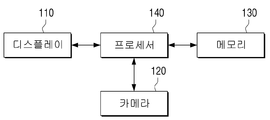
도 1은 참조하면, 전자 장치(100)는 디스플레이(110), 카메라(120), 메모리(130) 및 프로세서(140)를 포함한다.Referring to FIG. 1, the
디스플레이(110)는 전자 장치(100)을 통해 제공 가능한 다양한 컨텐츠 화면을 제공할 수 있다. 여기서, 컨텐츠 화면은 이미지, 동영상, 텍스트, 음악 등과 같은 다양한 컨텐츠, 어플리케이션 실행 화면, GUI(Graphic User Interface) 화면 등을 포함할 수 있다.The
디스플레이(110)는 LCD(Liquid Crystal Display), OLED(Organic Light Emitting Diodes) 디스플레이, PDP(Plasma Display Panel) 등과 같은 다양한 형태의 디스플레이로 구현될 수 있다. 디스플레이(110) 내에는 a-si TFT, LTPS(low temperature poly silicon) TFT, OTFT(organic TFT) 등과 같은 형태로 구현될 수 있는 구동 회로, 백라이트 유닛 등도 함께 포함될 수 있다. 한편, 디스플레이(110)는 터치 센서와 결합된 터치 스크린, 플렉시블 디스플레이(flexible display), 3차원 디스플레이(3D display) 등으로 구현될 수 있다.The
또한, 본 개시의 일 실시 예에 따른, 디스플레이(110)는 영상을 출력하는 디스플레이 패널뿐만 아니라, 디스플레이 패널을 하우징하는 베젤을 포함할 수 있다. 특히, 본 개시의 일 실시예에 따른, 베젤은 사용자 인터렉션을 감지하기 위한 터치 센서(미도시)를 포함할 수 있다.Also, according to an embodiment of the present disclosure, the
특히, 디스플레이(110)는 프로세서(140)의 제어에 따라 카메라(120)를 통해 실시간으로 촬영되는 영상(예를 들어, 라이브 뷰 영상), 해당 영상에 가상의 오브젝트 이미지가 추가된 AR(Augmented Reality, 증강현실) 영상 또는 후술하는 바와 같이 해당 영상에 기초하여 프로세서(140)가 획득한 영상 등을 디스플레이할 수 있다. 여기서, 가상 오브젝트 이미지는 AR 오브젝트, 가상 오브젝트 등으로 불릴 수 있으나, 이하에서는 설명의 편의상 가상 오브젝트 이미지로 통칭하도록 한다.In particular, the
본 개시의 일 실시 예에 따른 전자 장치(100)는 전면 또는 후면 상에 적어도 하나의 카메라(120)를 포함할 수 있다.The
카메라(120)는 정지 영상 및 동영상을 촬영할 수 있는 장치로서, 하나 이상의 이미지 센서(예를 들어, 전면 센서 또는 후면 센서), 렌즈, 이미지 시그널 프로세서(ISP), 플래시(예를 들어, LED, Xenon lamp 등)를 포함할 수 있다.The
본 개시의 일 실시 예에 따른 카메라(120)는 프로세서(140)의 제어에 따라 임의의 피사체를 촬영하고, 촬영된 데이터를 프로세서(140)로 전달할 수 있다. 촬영된 데이터는 프로세서(140)의 제어에 따라 메모리(130)에 저장될 수도 있음은 물론이다. 여기서, 촬영된 데이터는 픽쳐, 이미지, 정지 영상, 동영상 등 다양하게 불릴 수 있으나 이하에서는 설명의 편의를 위해 영상으로 통칭하도록 한다. 한편, 본 개시의 다양한 실시 예에 따른 영상은 카메라(120)를 통해 촬영되는 라이브 뷰 영상 외에도 외부 장치, 외부 서버로부터 수신된 영상, 메모리(130)에 저장된 영상 등을 의미할 수도 있음은 물론이다. The
본 개시의 일 실시 예에 따라, 프로세서(140)는 카메라(120)를 통해 촬영된 영상에 기초하여 증강현실(Augmented Reality) 화면을 디스플레이(110)를 통해 디스플레이할 수 있다. According to an embodiment of the present disclosure, the
메모리(130)는 전자 장치(100)를 구동시키기 위한 O/S(Operating System) 소프트웨어 모듈, 각종 멀티미디어 컨텐츠와 같은 다양한 데이터를 저장한다.The
특히, 메모리(130)는 프로세서(140)의 제어에 따라 카메라(120)를 통해 촬영된 영상에서 획득된 다양한 정보를 저장할 수 있다. 메모리(130)에 저장되는 다양한 정보에 대한 구체적인 설명은 후술하도록 한다.In particular, the
프로세서(140)는 디지털 신호를 처리하는 디지털 시그널 프로세서(digital signal processor(DSP), 마이크로 프로세서(microprocessor), TCON(Time controller)으로 구현될 수 있다. 다만, 이에 한정되는 것은 아니며, 중앙처리장치(central processing unit(CPU)), MCU(Micro Controller Unit), MPU(micro processing unit), 컨트롤러(controller), 어플리케이션 프로세서(application processor(AP)), GPU(graphics-processing unit) 또는 커뮤니케이션 프로세서(communication processor(CP)), ARM 프로세서 중 하나 또는 그 이상을 포함하거나, 해당 용어로 정의될 수 있다. 또한, 프로세서(140)는 프로세싱 알고리즘이 내장된 SoC(System on Chip), LSI(large scale integration)로 구현될 수도 있고, FPGA(Field Programmable gate array) 형태로 구현될 수도 있다. 프로세서(140)는 메모리에 저장된 컴퓨터 실행가능 명령어(computer executable instructions)를 실행함으로써 다양한 기능을 수행할 수 있다.The
본 개시의 일 실시 예에 따른 프로세서(140)는 카메라(120)를 통해 실시간으로 촬영되는 영상을 복수의 영상 구간으로 식별할 수 있다. 이에 대해서는 도 3을 참조하여 설명하도록 한다.The
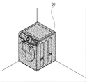
도 3은 본 개시의 일 실시 예에 따른 카메라를 통해 촬영된 영상을 설명하기 위한 도면이다.3 is a view for explaining an image photographed through a camera according to an embodiment of the present disclosure.
도 3을 참조하면, 카메라(120)는 프로세서(140)의 제어에 따라 현실 객체를 촬영하고, 프로세서(140)로 전송할 수 있다. 여기서, 현실 객체(예를 들어, 가구, 가전, 벽면, 배경 등)는 피사체를 의미할 수 있다.Referring to FIG. 3, the
본 개시의 일 실시 예에 따른 프로세서(140)는 카메라(120)를 통해 실시간으로 촬영되는 영상(10)을 디스플레이(110)를 통해 디스플레이 할 수 있다. 또한, 프로세서 (140)는 영상(10)을 저장할 수도 있음은 물론이다. 이어서, 프로세서(140)는 영상(10)을 복수의 영상 구간으로 식별할 수 있다.The
여기서, 영상 구간은 영상(10)을 단일 프레임, 기 설정된 개수의 프레임 또는 기 설정된 시간으로 구분한 구간 중 적어도 하나를 의미할 수 있다. 일 예로, 프로세서(140)는 영상(10)을 기 설정된 개수의 프레임 단위로 구분하여 제1 내지 제n 영상 구간을 획득할 수 있다. 기 설정된 개수는 다양하게 설정될 수 있다. 예를 들어, 프로세서(140)는 24, 30, 또는 60 프레임 단위로 영상 구간을 식별할 수 있다. 다만, 이는 일 실시 예로서 반드시 이에 한정되는 것은 아니다.Here, the image section may mean at least one of a section in which the
다른 예로, 프로세서(140)는 영상(10)을 기 설정된 시간 단위로 구분하여 제1 내지 제n 영상 구간을 획득할 수 있다. 예를 들어, 프로세서(140)는 10초 단위로 영상 구간을 식별할 수 있다. 영상(10)이 60fps(frame per second)이면, 프로세서(140)는 영상(10)을 600 프레임 단위로 구분하여 제1 내지 제n 영상 구간을 획득할 수 있다. 다만, 이는 일 실시 예로서 반드시 이에 한정되는 것은 아니다.As another example, the
본 개시의 일 실시 예에 따른 프로세서(140)는 영상 구간에 대응되는 공간 정보를 획득할 수 있다. 여기서, 공간 정보는 영상 구간에서 평면 공간에 대한 정보 및 카메라의 뷰 방향(view direction) 정보를 의미할 수 있다. 영상 구간에 대응되는 공간 정보는 도4를 참조하여 설명하도록 한다.The
도 4는 본 개시의 일 실시 예에 따른 공간 정보를 설명하기 위한 도면이다.4 is a diagram for describing spatial information according to an embodiment of the present disclosure.
본 개시의 일 실시 예에 따른 프로세서(140)는 영상 구간에서 평면 공간에 대한 정보(20?1) 및 카메라(120)의 뷰 방향 정보(20-2)를 획득하여 공간 정보(20)로 저장할 수 있다.The
본 개시의 일 실시 예에 따른 프로세서(140)는 영상 구간에서 평면 공간을 추정할 수 있다. 예를 들어, 공간 일관성(Spatial Coherency)에 따라 평면 공간을 구성하는 복수의 점들은 서로 인접하여 존재할 수 있다. 프로세서(140)는 서로 인접한 임의의 점들을 이용하여 영상 구간에서 평면 공간을 추정할 수 있다. 프로세서(140)는 인접한 임의의 점들이 동일 평면상에 존재하는지 여부를 식별하고, 식별 결과에 기초하여 평면 공간에 대한 정보(20-1)를 획득할 수 있다.The
예를 들어, 프로세서(140)는 서로 인접한(또는, 임계 값 이내로 이격된) 제1 내지 제 3 점을 이용하여 영상 구간에서 특정 공간이 평면 공간인지 여부를 식별할 수 있다. 식별 결과에 따라 특정 공간이 평면 공간이면, 프로세서(140)는 제1 내지 제3 점에 기초하여 평면 방정식의 계수(coefficient) A, B, C, D를 획득할 수 있다. 프로세서(140)는 하기의 수학식 1에 기초하여 평면 방정식을 평면 공간에 대한 정보(20-1)로 획득할 수 있다.For example, the
![]()
![]()
여기서, A, B, C는 평면의 방향을 나타내는 법선 벡터이고, D는 제1 내지 제3 점이 포함된 평면과 카메라(120) 간의 거리일 수 있다. 다만, 이는 일 실시 예로서, 평면 공간에 대한 정보(20-1)는 다양한 형태일 수 있다. 예를 들어, 프로세서(140)는 영상의 특성 정보를 획득하는 기계 학습(Machine Learning)된 모델에 기초하여 영상 구간을 분석하고, 분석 결과에 따라 평면 공간에 대한 정보(20-1)를 획득할 수도 있음은 물론이다.Here, A, B, and C are normal vectors representing the direction of the plane, and D may be a distance between the plane including the first to third points and the
본 개시의 일 실시 예에 따른 프로세서(140)는 영상 구간에서 카메라(120)의 뷰 방향 정보(20-2)를 획득할 수 있다. The
일 실시 예에 따른 카메라(120)의 뷰 방향(view direction)(또는 뷰 각도(view angle))에 대한 정보(20-2)는 카메라(120)로부터 수신되는 실시간 영상에 대응되는 카메라(120)가 바라보는 방향, 카메라(120)의 각도, 카메라(120)의 위치 또는 카메라(120)의 자세 중 적어도 하나를 의미할 수 있다. 도 4를 참조하면, 카메라(120)는 좌에서 우, 다시 우에서 좌 방향으로 이동하며 피사체를 촬영하였으며 피사체를 특정 각도 또는 자세로 촬영하였음을 알 수 있다.The information 20-2 for a view direction (or view angle) of the
본 개시의 일 실시 예에 따르면, 전자 장치(100)는 가속도 센서 또는 자이로 센서 중 적어도 하나를 포함할 수 있다. 일 실시 예에 따라, 프로세서(140)는 적어도 하나의 센서의 센싱 결과에 기초하여 전방위(예를 들어, 360도) 중 카메라(120)가 바라보는 뷰 방향(또는, 전자 장치(100)가 향하는 방향)에 대응되는 일정 각도(예를 들어, 전방위 360도 중 15도)를 뷰 방향 정보(20-2)로 획득할 수 있다. 한편, 센싱 결과를 통해 획득된 일정 각도는 카메라(120)의 자세(pose), 기울기 정도 등으로 불릴 수 있으나 이하에서는 설명의 편의를 위해 카메라(120)의 자세로 통칭하도록 한다.According to an embodiment of the present disclosure, the
다른 예로, 프로세서(140)는 센싱 결과에 기초하여 전자 장치(100)(또는, 카메라(120))의 현재 위치를 뷰 방향 정보(20-2)로 획득할 수 있다. As another example, the
또 다른 예로, 프로세서(140)는 카메라(120)로 현실 객체를 획득하고, 센서(예를 들어, GPS 센서)를 통해 전자 장치(100)의 현재 위치의 위치 정보(예를 들어, 위도/경도 정보)를 획득하고, 적어도 하나의 센서를 통해 기울기/중력 등의 센서 정보를 획득할 수도 있다.As another example, the
한편, 이는 일 실시 예로서 이에 한정되는 것은 아니다. 예를 들어, 전자 장치(100)는 GPS 센서, LBS(location-based services) 방식, 외부 장치로부터 수신된 위치 정보 또는 방향 정보, 디지털 나침반 등에 기초하여 카메라(120)의 뷰 방향 정보(20-2)를 획득할 수 있음은 물론이다.Meanwhile, the present invention is not limited thereto. For example, the
도 1로 돌아와서, 본 개시의 일 실시 예에 따른 프로세서(140)는 획득된 공간 정보를 복수의 영상 구간 각각에 맵핑시켜 메모리(130)에 저장할 수 있다.Returning to FIG. 1, the
일 실시 예에 따라, 프로세서(140)는 카메라(120)의 뷰 방향과 동일 선상(예를 들어 카메라(120)가 바라보는 뷰와 동일 방향, 동일 각도 또는 동일 자세)에 존재하는 평면 공간을 식별하고, 평면 공간에 대한 정보(20-1)을 카메라(120)의 뷰 방향 정보(20-2)와 함께 해당 영상 구간에 맵핑하여 저장할 수 있다. 도 4를 참조하면, 프로세서(140)는 특정 영상(10)과 이에 대응하는 평면 공간에 대한 정보(20-1) 및 카메라(120)의 뷰 방향 정보(20-2)를 맵핑하여 저장할 수 있다. 한편, 도 4에서 뷰 방향 정보(20-2)를 카메라(120)의 시선 이동 방향으로 상정하여 도시하였으나 이는 일 실시 예로서 이에 한정되는 것은 아니다. 예를 들어, 뷰 방향 정보(20-2)는 영상에서 카메라(120)의 뷰 방향에서 동일 선(또는, 일직 선(Straight line)) 상에 존재하는 피사체의 좌표 정보, 점 정보 등을 포함할 수도 있음은 물론이다.According to an embodiment of the present disclosure, the
본 개시의 일 실시 예에 따른 프로세서(140)는 가상 오브젝트 이미지를 영상(10)에 추가하기 위한 사용자 명령이 입력되면, 복수의 영상 구간 각각에 맵핑된 공간 정보에 기초하여 가상 오브젝트 이미지를 영상에 추가하여 디스플레이(110)를 통해 디스플레이할 수 있다. 이에 대해서는 도 5를 참조하여 구체적으로 설명하도록 한다.The
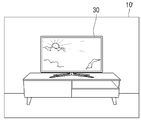
도 5는 본 개시의 일 실시 예에 따른 가상 오브젝트 이미지를 설명하기 위한 도면이다.5 is a view for explaining a virtual object image according to an embodiment of the present disclosure.
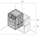
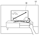
도 5를 참조하면, 사용자에 의해 선택된 가상 오브젝트 이미지(30)가 영상(10)에 추가될 수 있다. 여기서, 가상 오브젝트 이미지(30)는 사용자에 의해 선택된 가전, 가구 등에 대응되는 이미지를 의미할 수 있다. 일 실시 예에 따른 프로세서(140)는 사용자가 영상(10)에 추가할 수 있는 가상 오브젝트 이미지(30)의 리스트를 제공할 수 있고, 해당 리스트에서 사용자의 선택 명령에 대응되는 가상 오브젝트 이미지(30)를 영상(10)에 추가할 수 있다. 다만, 이는 일 실시 예로서 이에 한정되는 것은 아니다. 예를 들어, 프로세서(140)는 사용자가 특정 오브젝트(예를 들어, 가전 또는 가구)를 선택할 수 있는 다양한 형태의 UI(예를 들어, 검색 창 등)을 디스플레이할 수 있고, 사용자의 명령에 따라 선택된 오브젝트에 대응되는 가상 오브젝트 이미지(30)를 영상(10)에 추가할 수 있다. Referring to FIG. 5, a
도 5를 참조하면, 프로세서(140)는 복수의 영상 구간 각각에 맵핑된 평면 공간에 대한 정보(20-1) 및 뷰 방향 정보(20-2)를 획득할 수 있다. 이어서, 프로세서(140)는 복수의 영상 구간 각각에서 평면 공간에 대한 정보(20-1)에 기초하여 가상 오브젝트 이미지(30)를 추가하기 위한 위치 정보를 획득할 수 있다. 예를 들어, 프로세서(140)는 가상 오브젝트 이미지(30)를 영상(10)에 임의의 영역에 덮어 씌우는 것이 아니라, 평면 공간에 대한 정보(20-1)에 기초하여 영상(10) 내의 복수의 피사체 중 특정 피사체의 평면 공간에 가상 오브젝트 이미지(30)를 추가할 수 있다. 여기서, 특정 피사체의 평면 공간은 상술한 위치 정보를 의미할 수 있다.Referring to FIG. 5, the
이어서, 프로세서(140)는 뷰 방향 정보(20-2)에 대응되는 형상의 가상 오브젝트 이미지(30)를 획득할 수 있다. 예를 들어, 프로세서(140)는 3D 가상 오브젝트 이미지를 상이한 방향 또는 상이한 거리에서 캡쳐한 복수의 가상 오브젝트 이미지 중 뷰 방향 정보(20-2)에 대응되는 가상 오브젝트 이미지(30)를 획득할 수 있다. 일 예로, 프로세서(140)는 카메라(120)가 바라보는 뷰 방향, 각도 또는 자세에 대응되는 가상 오브젝트 이미지(30)가 오브젝트의 우측면도 또는 좌측면도이면, 프로세서(140)는 복수의 가상 오브젝트 이미지(30) 중 우측면도 또는 좌측면도를 획득하여 영상(10)에 추가할 수 있다. 다른 예로, 프로세서(140)는 카메라(120)가 바라보는 뷰 방향, 각도 또는 자세에 대응되는 가상 오브젝트 이미지(30)가 정면도이면, 프로세서(140)는 오브젝트의 정면도를 가상 오브젝트 이미지(30)로 획득하고, 영상(10)에 추가할 수 있다. Subsequently, the
구체적으로, 본 개시의 일 실시 예에 따른 프로세서(140)는 3D 메쉬 데이터(Mesh data) 형태의 3D 가상 오브젝트 이미지에 기초하여 가상 오브젝트 이미지(30)를 획득할 수 있다. 3D 메쉬 데이터를 획득하는 방법은 우선, 스캐닝 등을 통해 3D로 모델링 된 오브젝트에 대해 복수의 메쉬(Mesh)를 생성할 수 있다. 이어서, 3D의 오브젝트 형상의 표면을 형성하는 면에 대하여 다각형 메쉬를 생성할 수 있다. 여기서, 메쉬란 면(Face), 노드(Vertex) 및 에지(Edge)를 포함하는 닫힌 구조를 말한다. 예를 들어, 메쉬는 삼각형으로 이루어질 수 있으며, 사각형, 오각형 등의 다각형으로 이루어질 수도 있음은 물론이다. 메쉬의 크기 또는 면적이 주어지면, 모델링 된 형상에 따라 자동적으로 수십 내지 수만 개 정도의 메쉬가 형성될 수 있으며, 이러한 메쉬 생성을 통해 오브젝트를 3D 형상으로 모델링하고, 이를 활용하여 다양한 뷰 방향에 대응되는 가상 오브젝트 이미지(30)를 획득할 수 있다. 메쉬 데이터는 면(Face), 노드(Vertex) 및 에지(Edge)를 포함하는 메쉬를 표현할 수 있는 정보를 포함할 수 있다. 예를 들어, 메쉬 데이터는 하나의 메쉬에 대하여 각 노드의 좌표를 포함할 수 있으며, 프로세서(140)는 각 노드의 좌표를 알 수 있다면 각 노드의 좌표를 참조하여 3차원 메쉬 모델(예를 들어, 가상 오브젝트)을 보는 각도에 대응되는 가상 오브젝트 이미지(30)를 획득할 수 있다. 또한, 프로세서(140)는 3D 오브젝트 이미지에 기초하여 영상에 추가하기 위한 3D 가상 오브젝트의 형태 및 크기를 식별할 수 있다. 일 예로, 3D 메쉬 데이터에서 특정 노드를 절대 좌표계의 원점(0, 0, 0)으로 정의하고, 각 노드들의 위치를 산출하여 3D 가상 오브젝트의 형태 및 크기를 식별할 수 있다. 예를 들어, 노드 간의 거리가 멀어짐으로 인하여 각 노드의 좌표의 절대값이 증가하고, 프로세서(140)는 절대값에 기초하여 3D 가상 오브젝트의 형태(또는, 형상) 및 크기를 식별할 수 있다.Specifically, the
이와 같은 3D 메쉬 데이터는 전자 장치(100)에 기 저장되어 있을 수도 있고, 서버와 통신을 수행하여 수신할 수도 있고, 자체적으로 생성할 수도 있음은 물론이다. 프로세서(140)는 선택된 오브젝트에 대응되는 3D 메쉬 데이터로부터 카메라(120)가 바라보는 뷰 방향에 기초하여 가상 오브젝트 이미지(30)를 획득할 수 있다. 한편, 메쉬 데이터 형태의 3D 가상 오브젝트 이미지는 일 실시 예일 뿐, 반드시 이에 한정되는 것은 아니다. 예를 들어, 프로세서(140)는 오브젝트가 다양한 방향, 다양한 거리에서 촬영된 복수의 2D 이미지로부터 카메라(120)의 뷰 방향에 대응되는 가상 오브젝트 이미지(30)를 획득할 수도 있고, 카메라(120)의 뷰 방향에 대응되는 가상 오브젝트 이미지(30)를 생성 및 출력하는 신경망 알고리즘에 기초하여 획득할 수도 있음은 물론이다. 이하에서는 설명의 편의를 위해 3D 가상 오브젝트 이미지가 메쉬 데이터의 형태임을 상정하여 설명하도록 한다.Of course, the 3D mesh data may be pre-stored in the
한편, 도 5에서 프로세서(140)가 카메라(120)를 통해 실시간으로 촬영되는 영상(10)에 가상 오브젝트 이미지(30)를 추가한 영상(10’)을 디스플레이(110)를 통해 디스플레이하는 것으로 상정하여 설명하였으나, 반드시 이에 한정되는 것은 아니다. 예를 들어, 프로세서(140)는 영상(10)이 촬영된 장소와 상이한 장소에서 메모리(130)에 저장된 공간 정보(20)에 기초하여 영상(10)에 가상 오브젝트 이미지(30)를 추가한 영상(10’)을 디스플레이 할 수도 있음은 물론이다.Meanwhile, in FIG. 5, it is assumed that the
종래와 같이 가상 오브젝트 이미지(30)를 영상(10)의 일정 영역에 오버레이시키는 것에 그치는 것이 아니라, 본 개시의 일 실시 예에 따른 프로세서(140)는 메모리(130)에 저장된 영상 구간 및 해당 영상 구간에 맵핑된 공간 정보에 기초하여 가상 오브젝트 이미지(30)를 해당 영상 구간에 추가할 수 있다. Rather than just overlaying a
도 1로 돌아와서, 프로세서(140)는 복수의 영상 구간 중 적어도 하나의 구간에서 획득된 공간 정보(20)에 기초하여 가상 오브젝트 이미지(30)를 추가하기 위한 위치 정보가 복수 개 획득되면, 이전에 가상 오브젝트 이미지를 영상(10) 추가한 히스토리 정보에 기초하여 복수 개의 위치 정보 중 하나를 식별할 수 있다. 이에 대한 구체적인 설명은 도 6을 참조하여 하도록 한다.Returning to FIG. 1, when the
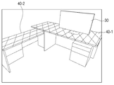
도 6은 본 개시의 일 실시 예에 따른 복수 개의 위치 정보를 설명하기 위한 도면이다. 6 is a view for explaining a plurality of location information according to an embodiment of the present disclosure.
도 6을 참조하면, 프로세서(140)는 복수의 영상 구간 각각에서 평면 공간에 대한 위치 정보(20-1)에 기초하여 가상 오브젝트 이미지(30)를 추가하기 위한 위치 정보를 획득할 수 있다. 예를 들어, 프로세서(140)는 평면 공간에 대한 위치 정보(20-1)에 기초하여 영상 내에서 복수의 평면 공간을 식별할 수 있고, 복수의 평면 공간에서 제1 평면 공간 및 제2 평면 공간을 가상 오브젝트 이미지(30)를 추가하기 위한 위치 정보로 식별할 수 있다. 프로세서(140)는 식별된 위치 정보 중 어느 하나에 가상 오브젝트 이미지(30)를 추가할 수 있다.Referring to FIG. 6, the
본 개시의 일 실시 예에 따른 프로세서(140)는 가상 오브젝트 이미지(30)를 추가하기 위한 위치 정보가 복수 개 획득되면, 이전에 가상 오브젝트 이미지를 추가한 히스토리 정보에 기초하여 복수 개의 위치 정보 중 어느 하나를 식별할 수 있다. 이어서, 식별된 위치 정보에 가상 오브젝트 이미지(30)를 추가할 수 있다.When a plurality of location information for adding the
도 6을 참조하면, 프로세서(140)는 영상 구간에서 평면 공간에 대한 위치 정보(20-1)에 기초하여 제1 위치 정보(40-1)로 제1 테이블 상의 평면 공간을 식별하고, 제2 위치 정보(40-2)로 제2 테이블 상의 평면 공간을 식별할 수 있다. 이어서, 프로세서(140)는 제1 및 제2 위치 정보(40-1, 40-2) 중 이전에 가상 오브젝트 이미지가 추가되었던 적이 있는 어느 하나의 위치 정보를 획득할 수 있다. 예를 들어, 이전에 제1 위치 정보(40-1)에 대응되는 제1 테이블 상에 가상의 가상 오브젝트 이미지가 추가된 증강 현실 화면이 디스플레이되었던 이력이 있다면, 프로세서(140)는 이와 같은 히스토리 정보에 기초하여 제1 및 제2 위치 정보(40-1, 40-2) 중 제1 위치 정보(40-1)를 획득하고, 획득된 제1 위치 정보(40-1)에 가상 오브젝트 이미지(30)를 추가할 수 있다. 한편, 이는 일 실시 예로 이에 한정되는 것은 아니다.Referring to FIG. 6, the
다른 예로, 프로세서(140)는 영상 구간에서 평면 공간에 대한 정보(20-1)에 기초하여 가상 오브젝트 이미지(30)를 추가하기 위한 복수의 위치 정보가 식별되면, 복수의 위치 정보 중 가장 넓은 면적의 평면 공간에 대응되는 위치 정보를 식별할 수 있다. 또 다른 예로, 바닥(Floor) 평면을 기준으로 임계 값 이상의 높이에 위치하는 평면 공간에 대응되는 위치 정보를 식별할 수 있다. 이어서, 프로세서(140)는 식별된 위치 정보에 가상 오브젝트 이미지(30)를 추가할 수 있다. As another example, when the plurality of location information for adding the
도 1로 돌아와서, 프로세서(140)는 복수의 영상 구간 각각에서 획득된 카메라(120)의 뷰 방향 정보(20-2)에 기초하여 복수의 영상 구간의 순서가 재배열된 영상을 획득하고, 획득된 영상의 재생 시점을 조정하기 위한 네비게이션 바를 영상과 함께 디스플레이할 수 있다. 이에 대한 구체적인 설명은 도 7 및 도 8을 참조하여 하도록 한다.Returning to FIG. 1, the
도 7은 본 개시의 일 실시 예에 따른 카메라의 뷰 방향 정보를 설명하기 위한 도면이다.7 is a view for explaining view direction information of a camera according to an embodiment of the present disclosure.
영상(10)에서 카메라(120)의 이동 방향은 좌측에서 우측(또는, 우측에서 좌측) 또는 위에서 아래(또는, 아래에서 위)로 일정하지 않을 수 있다. 또한, 촬영 시에 카메라(120)의 흔들림으로 인해 영상(10)의 떨림이 생길 수 있다. 사용자에 의해 자유롭게 촬영된 영상(10)은 특정한 방향성을 가지지 않을 수 있다.The moving direction of the
도 7을 참조하면, 카메라(120)가 제1 방향에서 제2 방향으로 이동하고, 다시 제1 방향으로 이동함에 따라 촬영된 영상이 있을 수 있다. Referring to FIG. 7, as the
본 개시의 일 실시 예에 따른 프로세서(140)는 카메라(120)의 뷰 방향 정보(20-2)에 기초하여 복수의 영상 구간의 순서가 재배열된 영상을 획득할 수 있다. 일 예로, 영상(10)이 제1 내지 제7 영상 구간을 포함하는 경우를 상정할 수 있다. 프로세서(140)는 뷰 방향 정보(20-2)에 기초하여 제1 내지 제4 영상 구간은 제1 방향에서 제2 방향으로 이동하는 방향성을 가지고, 제5 내지 제7 영상 구간은 제2 방향에서 제1 방향으로 이동하는 방향성을 가지는 것을 식별할 수 있다. 프로세서(140)가 복수의 영상 구간의 순서가 재배열된 영상을 획득하는 구체적인 실시 예는 도 8을 참조하여 설명하도록 한다.The
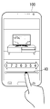
도 8은 본 개시의 일 실시 예에 따른 네비게이션 바를 설명하기 위한 도면이다.8 is a view for explaining a navigation bar according to an embodiment of the present disclosure.
본 개시의 일 실시 예에 따른 프로세서(140)는 뷰 방향 정보(20-2)에 기초하여 카메라(120)의 뷰 이동 방향이 특정한 방향성을 가지도록 복수의 영상 구간을 재배열할 수 있다.The
예를 들어, 도 7에 도시된 바와 같이 제1 내지 제7의 시점 각각에서 촬영된 정지 영상(또는, 기 설정된 개수의 프레임을 가지는 영상)을 촬영 시간 순서로 배열하면, 카메라(120)의 뷰 방향은 좌측에서 우측으로 이동한 뒤 다시 좌측으로 이동하게 된다. 다만, 도 8에 도시된 바와 같이 프로세서(140)는 제1 내지 제7 시점 각각에서 촬영된 정지 영상을 뷰 방향 정보(20-2)에 기초하여 특정한 방향성을 가지도록 재배열한 영상을 획득할 수 있다. 예를 들어, 프로세서(140)는 제1, 제7, 제2, 제6, 제3, 제5, 제 4 영상 구간 순서로 재배열된 영상을 획득할 수 있다. 다만, 이는 일 실시 예로서 본 개시의 다양한 실시 예에 따른 프로세서(140)는 다양한 기준에 따라 복수의 영상 구간이 재배열된 영상을 획득할 수도 있음은 물론이다. 예를 들어, 프로세서(140)는 바닥(Floor) 평면을 기준으로 위에서 아래로 이동하는 방향성을 가지도록 복수의 영상 구간을 배열할 수도 있고, 아래에서 위로 이동하는 방향성을 가지도록 복수의 영상 구간을 배열할 수도 있다.For example, as shown in FIG. 7, when the still images (or images having a predetermined number of frames) photographed at each of the first to seventh viewpoints are arranged in the order of shooting time, the view of the
본 개시의 일 실시 예에 따른 프로세서(140)는 재배열된 영상의 재생 시점을 조정하기 위한 네비게이션 바(40)를 영상과 함께 디스플레이할 수 있다. 여기서, 프로세서(140)는 재배열된 복수의 영상 구간이 가지는 특정한 방향성에 기초하여 네비게이션 바(40)를 생성 및 디스플레이할 수 있다. 예를 들어, 방향성이 좌에서 우이면 가로 형태의 네비게이션 바를 생성하고, 방향성이 위에서 아래이면 세로 형태의 네비게이션 바를 생성할 수 있다. 다만, 이는 일 실시 예로 이에 한정되는 것은 아니다. 예를 들어, 프로세서(140)는 순서가 재배열된 복수의 영상 구간이 전방향 360도의 방향성을 가지면, 원형 형태의 네비게이션 바를 생성 및 디스플레이할 수도 있음은 물론이다.The
본 개시의 일 실시 예에 따른 프로세서(140)는 카메라(120)를 통한 영상의 촬영 시에 이동 방향을 가이드하는 가이드 UI를 디스플레이할 수도 있음은 물론이다. 여기서, 가이드 UI는 카메라(120)가 제1 방향에서 제2 방향으로 이동하도록 가이드하는 UI 이고, 가이드 UI에 따라 촬영된 영상은 카메라(130)의 뷰 이동 방향이 특정한 방향성을 가질 수 있다.Of course, the
도 1로 돌아와서, 본 개시의 일 실시 예에 따른 프로세서(140)는 복수의 영상 구간 각각에 포함된 오브젝트에 대한 정보를 획득하여 공간 정보(20)로 저장할 수 있다. 이어서, 프로세서(140)는 복수의 영상 구간 각각에서 오브젝트에 대한 정보에 기초하여 오브젝트 상의 일 영역에 가상 오브젝트 이미지(30)를 추가하기 위한 위치 정보를 획득할 수 있다. 프로세서(140)가 오브젝트를 식별하고, 오브젝트 상에 가상 오브젝트 이미지(30)를 추가하는 방법에 대해서는 도 9a 및 도 9b를 참조하여 하도록 한다. Returning to FIG. 1, the
도 9a는 본 개시의 일 실시 예에 따른 오브젝트를 식별하는 방법을 설명하기 위한 도면이다.9A is a diagram for describing a method of identifying an object according to an embodiment of the present disclosure.
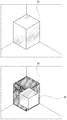
도 9a를 참조하면, 본 개시의 일 실시 예에 따른 프로세서(140)는 복수의 영상 구간 각각에 포함된 오브젝트(50)를 식별하고, 오브젝트(50)에 대한 정보를 획득할 수 있다. 일 예로, 프로세서(140)는 영상을 학습 네트워크 모델에 적용하여, 복수의 영상 구간 각각에 포함된 오브젝트(50)에 대한 정보를 획득할 수 있다. 예를 들어, 학습 네트워크 모델(50)은 복수의 영상 구간 각각에 포함된 오브젝트(50)의 종류를 식별할 수 있다. 이어서, 학습 네트워크 모델(50)은 식별된 오브젝트(50)의 종류에 기초하여 해당 오브젝트(50)의 형태 또는 크기 중 적어도 하나를 식별할 수 있다. 일 예로, 학습 네트워크 모델(50)은 복수의 오브젝트(50) 각각에 대한 형태 또는 크기 정보 중 적어도 하나를 포함하는 오브젝트(50)에 대한 정보를 포함할 수 있다. 학습 네트워크 모델은 식별된 오브젝트(50)에 대응되는 오브젝트(50)에 대한 정보에 기초하여 오브젝트(50)의 형태 또는 크기 중 적어도 하나를 식별할 수 있다. 여기서, 오브젝트(50)의 형태는 해당 오브젝트(50)와 외부와의 경계 면에 따라 정의되는 오브젝트(50)의 개략적인 형상, 모양 등으로서, 직육면체, 정육면체, 원형, 타원형 등을 의미할 수 있다. 오브젝트(50)의 크기는 해당 오브젝트의 너비(Width 또는, 가로), 높이(Height), 깊이(Depth) 길이에 기초하여 W*H*D(mm)정보를 포함할 수 있다. 여기서, 길이 단위는 mm에 한정되지 않음은 물론이며, 인치(in), 피트(ft) 등 다양한 단위에 기초하여 해당 오브젝트(50)의 크기가 표현될 수 있음은 물론이다. Referring to FIG. 9A, the
도 9a를 참조하면, 학습 네트워크 모델은 복수의 영상 구간 각각에 포함된 오브젝트(50)의 종류가 세탁기임을 식별할 수 있고, 세탁기의 형태 또는 크기 중 적어도 하나를 포함하는 세탁기에 대한 정보를 획득할 수 있다. 예를 들어, 학습 네트워크 모델은 세탁기의 형태로서 직육면체를 식별하고, 오브젝트(50)의 크기 정보로서 직육면체의 크기를 정의하는 너비, 높이, 깊이의 길이에 대한 정보를 획득할 수 있다.Referring to FIG. 9A, the learning network model may identify that the type of the
여기서, 학습 네트워크 모델은 복수의 샘플 영상에 기초하여 CNN(Convolution Neural Network, 컨벌루션 신경망) 학습된 모델일 수 있다. 여기서, CNN은 이미지 처리, 음성처리, 객체 식별 등을 위해 고안된 특수한 연결구조를 가진 다층신경망이다. 특히, CNN은 입력 영상에 포함된 픽셀에 전처리를 통하여 영상을 다양하게 필터링하고, 영상의 특성을 인식할 수 있다. 일 예로, 영상에 포함된 오브젝트의 종류, 형태, 크기 중 적어도 하나를 인식할 수 있다. 한편, 학습 네트워크 모델은 CNN에 한정되지 않음은 물론이다. 예를 들어, 영상 처리 장치(100)는 RNN(Recurrent Neural Network), DNN(Deep Neural Network), GAN(Generative adversarial network) 등 다양한 신경망(Neural Network)에 기반한 학습 네트워크 모델을 이용할 수 있음은 물론이다. Here, the learning network model may be a CNN (Convolution Neural Network) trained model based on a plurality of sample images. Here, CNN is a multilayer neural network having a special connection structure designed for image processing, voice processing, and object identification. In particular, the CNN can filter the image in various ways through pre-processing the pixels included in the input image and recognize characteristics of the image. For example, at least one of a type, shape, and size of an object included in an image may be recognized. On the other hand, of course, the learning network model is not limited to CNN. For example, the
다른 예로, 본 개시의 일 실시 예에 따른 프로세서(140)는 복수의 영상 구간 각각을 분석하여, 오브젝트(50)의 외관 정보를 획득할 수 있다. 일 예로, 프로세서(140)는 오브젝트(50)의 외곽 테두리 선에 기초하여 오브젝트(50)의 2D 형상을 식별할 수 있다. 이어서, 프로세서(140)는 오브젝트(50)를 상이한 뷰 방향 또는 상이한 거리에서 캡쳐한 복수의 2D 이미지 중 식별된 2D 형상과 유사도가 임계 값 이상인 2D 이미지를 식별할 수 있다. 이어서, 프로세서(140)는 식별된 2D 이미지에 기초하여 영상에 포함된 오브젝트(50)의 종류, 형태 또는 크기 중 적어도 하나를 식별할 수 있다.As another example, the
일 예로, 도 9a를 참조하면, 프로세서(140)는 영상에 포함된 오브젝트(50)의 외곽 테두리 선에 기초하여 2D 형상이 마름모 꼴로 식별되면, 카메라(120)의 뷰 방향, 각도 또는 자세에서 식별된 마름모 꼴과 임계 값 이상의 유사도를 가지는 오브젝트(50)를 식별할 수 있다. 식별된 오브젝트(50)가 세탁기이면, 프로세서(140)는 세탁기의 형태, 크기를 포함하는 정보를 획득할 수 있다.For example, referring to FIG. 9A, when the 2D shape is identified in a rhombus shape based on the outer border line of the
또한, 본 개시의 일 실시 예에 따른 프로세서(140)는 오브젝트(50)의 위치를 식별할 수도 있다. 일 예로, 프로세서(140)는 영상을 학습 네트워크 모델에 적용하여 공간의 형태를 식별하고, 오브젝트(50)의 위치를 식별할 수 있다. 예를 들어, 학습 네트워크 모델은 공간을 둘러 싸는 벽면 또는 공간에 위치하는 가구, 계단, 가전기기, 문턱(threshold) 등을 기준으로 공간의 면적, 크기, 모양 등을 식별하고, 오브젝트(50)의 위치를 식별할 수도 있다.Further, the
이어서, 본 개시의 일 실시 예에 따른 프로세서(140)는 복수의 영상 구간 각각에서 오브젝트(50)에 대한 위치 정보에 기초하여 오브젝트(50) 상의 일 영역에 가상 오브젝트 이미지(30)를 추가하기 위한 위치 정보를 획득할 수 있다. 이어서, 프로세서(140)는 카메라(120)의 뷰 방향 정보에 대응되는 형상의 가상 오브젝트 이미지(30)를 획득하고, 위치 정보에 기초하여 획득된 가상 오브젝트 이미지(30)를 대응되는 영상 구간에 추가하여 제공할 수 있다.Subsequently, the
도 9b는 본 개시의 일 실시 예에 따른 가상 오브젝트 이미지를 추가하는 방법을 설명하기 위한 도면이다.9B is a diagram illustrating a method of adding a virtual object image according to an embodiment of the present disclosure.
도 9b를 참조하면, 프로세서(140)는 오브젝트(50)에 대한 정보에 기초하여 가상 오브젝트 이미지(30)를 추가할 수 있는 일 영역을 식별할 수 있다. 예를 들어, 프로세서(140)는 오브젝트(50)에 대한 정보에 포함된 오브젝트(50)의 형태에 기초하여 가상 오브젝트 이미지(30)를 추가하기 위한 위치 정보를 획득할 수 있다. 도 9b에 도시된 바와 같이, 프로세서(140)는 세탁기의 직육면체 형태에 기초하여 상단에 가상 오브젝트 이미지(30)의 추가가 가능함을 식별할 수 있다. 이어서, 프로세서(140)는 카메라(120)의 뷰 방향 정보에 대응되는 형상의 가상 오브젝트 이미지(30)를 획득하고, 위치 정보에 기초하여 획득된 가상 오브젝트 이미지를 대응되는 영상 구간에 추가할 수 있다. 전자 장치(100)는 공간에 실재하는 오브젝트(50)와 가상 오브젝트 이미지(30)를 하나의 영상을 통해 제공할 수 있다. 한편, 추가된 가상 오브젝트 이미지(30)는 사용자 명령에 따라 위치, 크기 등이 변경될 수도 있음은 물론이다. 예를 들어, 도 9b에 도시된 바와 같이 가상 오브젝트 이미지(30)의 위치는 오브젝트(50)의 상측에 고정되는 것이 아니며, 사용자 조작에 따라 공간 바닥의 평면 공간에 위치할 수도 있음은 물론이다.Referring to FIG. 9B, the
한편, 프로세서(140)는 오브젝트(50)에 대한 정보에 포함된 오브젝트(50)의 크기에 기초하여 가상 오브젝트 이미지(30)의 크기를 조절하여 영상 구간에 추가할 수 있다. 일 실시 예에 따른 프로세서(140)는 위치 정보 및 3D 메쉬 데이터에 기초하여 가상 오브젝트 이미지(30)의 크기를 리사이징하여 추가할 수 있다. 일 예로, 프로세서(140)는 가상 오브젝트 이미지(30)를 추가하기 위한 위치 정보에 따라 식별된 오브젝트(50) 상의 면적이 가상 오브젝트 이미지(30)의 크기에 비해 작은 것으로 판단되면, 위치 정보에 기초하여 가상 오브젝트 이미지(30)의 크기를 조정한 뒤 영상 구간에 추가할 수 있다. 한편, 이는 일 실시 예로서 반드시 가상 오브젝트 이미지(30)의 크기가 작아지도록 리사이징되어야 하는 것은 아니다. 예를 들어, 프로세서(140)는 오브젝트(50)의 크기와 3D 가상 오브젝트의 메쉬 데이터에 기초한 크기에 기초하여 가상 오브젝트 이미지(30)의 크기를 오브젝트(50)의 실제 크기에 비례하도록 조정하여 영상 구간에 추가할 수도 있다. Meanwhile, the
도 1로 돌아와서, 본 개시의 일 실시 예에 따른 프로세서(140)는 가상 오브젝트 이미지(30) 상의 일 영역에 타 가상 오브젝트 이미지를 추가하기 위한 사용자 명령이 입력되면, 가상 오브젝트 이미지(30)에 대한 정보에 기초하여 타 가상 오브젝트 이미지를 가상 오브젝트 이미지 상에 적층되는 형태로 디스플레이되도록 디스플레이(110)를 제어할 수 있다. 이에 대한 구체적인 설명은 도 10을 참조하여 하도록 한다.Returning to FIG. 1, when a user command for adding another virtual object image to a region on the
도 10은 본 개시의 일 실시 예에 따른 복수의 가상 오브젝트 이미지를 설명하기 위한 도면이다.10 is a view for explaining a plurality of virtual object images according to an embodiment of the present disclosure.
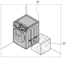
도 10을 참조하면, 프로세서(140)는 영상에 복수의 가상 오브젝트 이미지를 추가할 수 있다. 예를 들어, 프로세서(140)는 가상 오브젝트 이미지(30)가 영상 구간에 추가된 뒤, 사용자 명령에 따라 타 가상 오브젝트 이미지(30’)를 영상 구간에 추가할 수 있다. 이 경우, 프로세서(140)는 가상 오브젝트 이미지(30)에 대한 정보에 기초하여 타 가상 오브젝트 이미지(30’)를 영상 구간에 추가할 수 있다. 여기서, 가상 오브젝트 이미지(30)에 대한 정보는 가상 오브젝트 이미지(30)에 대응되는 3D 가상 오브젝트의 메쉬 데이터를 의미할 수 있다. 프로세서(140)는 3D 가상 오브젝트의 메쉬 데이터에 기초하여 가상 오브젝트 이미지(30)의 형태, 크기 등을 식별할 수 있고, 타 가상 오브젝트 이미지(30’)를 영상 구간에 추가함에 있어서, 가상 오브젝트 이미지(30)의 형태, 크기를 고려할 수 있다. 여기서, 가상 오브젝트 이미지(30)의 크기는 해당 가상 오브젝트 이미지(30)의 높이, 너비, 깊이를 의미할 수 있다. Referring to FIG. 10, the
도 10에 도시된 바와 같이, 프로세서(140)는 가상 오브젝트 이미지(30)의 크기에 기초하여 바닥으로부터 가상 오브젝트 이미지(30)의 높이만큼 이격된 위치에 타 가상 오브젝트 이미지(30’)를 추가할 수 있다. 프로세서(140)는 가상 오브젝트 이미지(30)와 타 가상 오브젝트 이미지(30’) 상호 작용(interaction)된 영상을 제공함에 따라, 사용자에게 가상 오브젝트 이미지(30) 및 타 가상 오브젝트 이미지(30’)가 실재하는 것과 같은 영상을 제공할 수 있다.As shown in FIG. 10, the
도 1로 돌아와서, 본 개시의 일 실시 예에 따른 프로세서(140)는 가상 오브젝트 이미지(30)를 제거하기 위한 명령이 입력되면, 가상 오브젝트 이미지(30)를 제거할 수 있다. 이어서, 프로세서(140)는 가상 오브젝트 이미지(30) 상에 적층되는 형태로 추가된 타 가상 오브젝트 이미지(30’)의 위치를 조정할 수 있다. 이에 대한 구체적인 설명은 도 11을 참조하여 하도록 한다.Returning to FIG. 1, when a command for removing the
도 11은 본 개시의 일 실시 예에 따른 가상 오브젝트 이미지를 제거하는 경우를 설명하기 위한 도면이다.11 is a view for explaining a case of removing a virtual object image according to an embodiment of the present disclosure.
도 11을 참조하면, 프로세서(140)는 사용자 명령에 따라 영상 구간에 추가된 가상 오브젝트 이미지(30)를 제거할 수 있다. 도 10에 도시된 바와 같이, 가상 오브젝트 이미지(30) 상에 적층되는 형태로 추가된 타 가상 오브젝트 이미지(30’)에 대한 제거 명령이 수신되면, 프로세서(140)는 타 가상 오브젝트 이미지(30’)는 제거하고 가상 오브젝트 이미지(30)는 유지할 수 있다.Referring to FIG. 11, the
다른 예로, 타 가상 오브젝트 이미지(30’)의 하단에 위치한 가상 오브젝트 이미지(30)에 대한 제거 명령이 수신되면, 프로세서(140)는 가상 오브젝트 이미지(30)를 제거한 뒤 타 가상 오브젝트 이미지(30’)의 위치를 조정할 수 있다. 프로세서(140)는 가상 오브젝트 이미지(30)에 대한 정보에 기초하여 타 가상 오브젝트 이미지(30’)를 추가하였으며, 가상 오브젝트 이미지(30)의 높이만큼 바닥으로부터 이격된 위치에 타 가상 오브젝트 이미지(30’)를 추가하였으므로, 가상 오브젝트 이미지(30)의 제거 명령에 따라 타 가상 오브젝트 이미지(30’)를 추가하기 위한 새로운 위치 정보를 식별할 수 있다. As another example, when a removal command for the
일 예로, 프로세서(140)는 오브젝트(50)에 대한 정보 및 평면 공간에 대한 정보(20-1)에 기초하여 타 가상 오브젝트 이미지(30’)의 위치를 조정하기 위한 위치 정보를 재획득할 수 있다. 이어서, 프로세서(140)는 재획득된 위치 정보에 기초하여 타 가상 오브젝트 이미지(30’)의 위치를 조정할 수 있다. 한편, 프로세서(140)는 복수의 위치 정보가 재획득되면, 복수의 위치 정보 중 종래의 타 가상 오브젝트 이미지(30’)가 위치한 위치 정보와 차이를 최소화하는 하나의 위치 정보를 식별할 수 있다. 일 예로, 도 11을 참조하면, 프로세서(140)는 오브젝트(50) 상의 일 영역 및 바닥의 평면 공간 상의 일 영역을 위치 정보로 획득할 수 있다. 이어서, 프로세서(140)는 x, y, z 축으로 정의되는 타 가상 오브젝트 이미지(30’)의 위치 좌표 값에서 바닥의 평면 공간 상의 일 영역으로의 위치 이동이, 오브젝트(50) 상의 일 영역으로의 위치 이동과는 달리 하나의 축(예를 들어, y축)의 위치 좌표 값만의 변경을 요하므로, 타 가상 오브젝트 이미지(30’)를 바닥 평면 공간 상의 일 영역으로 이동시킬 수 있다. 프로세서(140)는 타 오브젝트 이미지(30’)를 오브젝트 이미지(30)가 제거된 위치에 디스플레이하도록 디스플레이(110)를 제어할 수 있다.For example, the
다른 예로, 프로세서(140)는 물리 엔진(physics engine)에 기초하여 가상 오브젝트 이미지(30) 및 타 가상 오브젝트 이미지(30’)가 적층된 상태에서, 가상 오브젝트 이미지(30)에 대한 제거 명령이 입력되면, 타 가상 오브젝트 이미지(30’)가 중력에 따라 바닥의 평면 공간으로 떨어지는 듯한 시각적 피드백을 제공할 수도 있다.As another example, the
도 1로 돌아와서, 본 개시의 일 실시 예에 따른 프로세서(140)는 복수의 영상 구간 각각에 포함된 오브젝트(50)에 대한 정보 및 오브젝트(50)가 위치한 공간의 형태 정보를 획득하여 공간 정보(20)로 저장하며, 오브젝트(50)를 가상 오브젝트로 대체하기 위한 사용자 명령이 입력되면, 오브젝트(50)에 대한 정보 및 공간의 형태 정보에 기초하여 가상 오브젝트 이미지(30)를 오브젝트(50)에 오버랩시켜 디스플레이할 수 있다. 이에 대한 구체적인 설명은 도 12를 참조하여 하도록 한다.Returning to FIG. 1, the
도 12는 본 개시의 일 실시 예에 따른 오브젝트를 대체하는 방법을 설명하기 위한 도면이다.12 is a view for explaining a method of replacing an object according to an embodiment of the present disclosure.
도 12를 참조하면, 본 개시의 일 실시 예에 따른 프로세서(140)는 복수의 영상 구간을 분석하여 오브젝트(50)가 위치한 공간의 형태 정보를 획득할 수 있다. 일 예로, 프로세서(140)는 복수의 영상 구간을 학습 네트워크 모델에 적용하여 공간의 형태를 식별할 수 있다. 여기서, 공간의 형태 정보는 공간을 둘러 싸는 벽면 또는 공간에 위치하는 가구, 계단, 가전기기, 문턱(threshold) 등을 기준으로 공간의 면적, 크기, 모양 정보를 포함할 수 있다.Referring to FIG. 12, the
이어서, 본 개시의 일 실시 예에 따른 프로세서(140)는 영상 구간에 포함된 오브젝트(50)를 3D 가상 오브젝트로 대체하기 위한 사용자 명령이 입력되면, 오브젝트(50)에 대한 정보에 기초하여 가상 오브젝트 이미지(30)를 오브젝트(50)에 오버랩시켜 디스플레이할 수 있다.Subsequently, when a user command for replacing the
여기서, 프로세서(140)는 공간의 형태 정보에 기초하여 가상 오브젝트 이미지(30)가 오브젝트(50) 외에 벽면, 문턱을 통과하여 추가되는 것을 방지할 수 있다. 한편, 본 개시의 일 실시 예에 따른 프로세서(140)는 3D 가상 오브젝트에 대한 정보 즉, 메쉬 데이터에 기초하여 3D 가상 오브젝트의 형태 및 크기 정보를 획득할 수 있다. 이어서, 프로세서(140)는 오브젝트(50)의 크기 대비 3D 가상 오브젝트의 크기가 크면, 도 12의 상단에 도시된 바와 같이 3D 가상 오브젝트에 대응되는 가상 오브젝트 이미지(30)를 오브젝트(50)에 오버랩시켜 디스플레이할 수 있다. 한편, 가상 오브젝트 이미지(30)의 위치, 크기는 사용자 입력에 따라 변경될 수 있음은 물론이다.Here, the
다른 예로, 프로세서(140)는 3D 가상 오브젝트의 크기 대비 오브젝트(50)의 크기가 크면, 도 12의 하단에 도시된 바와 같이 3D 가상 오브젝트에 대응되는 가상 오브젝트 이미지(30)를 오브젝트(50)의 일 영역에 오버랩시켜 디스플레이할 수 있다. As another example, when the size of the
도 13은 본 개시의 일 실시 예에 따른 오브젝트 및 가상 오브젝트 이미지의 상호 작용을 설명하기 위한 도면이다.13 is a diagram for describing an interaction between an object and a virtual object image according to an embodiment of the present disclosure.
도 13을 참조하면, 본 개시의 일 실시 예에 따른 프로세서(140)는 가상 오브젝트 이미지(30)를 추가하기 위해 뎁스 데이터(depth data)를 이용할 수 있다. 여기서, 뎁스 데이터는 카메라(120)와 오브젝트(50)간 거리 데이터를 의미할 수 있다. 일 실시 예에 따른 전자 장치(100)에 구비된 카메라(120)는 뎁스 카메라(Depth camera)를 포함할 수 있다. 일 실시 예에 따른 뎁스 카메라는 TOF(Time Of Flight) 방식을 이용하여 광의 방출 후 반사되어 오는 시간을 측정할 수 있다. 이어서, 프로세서(140)는 측정된 TOF에 기초하여 카메라(120)와 오브젝트(50) 간의 거리를 산출할 수 있다. 이어서, 프로세서(140)는 오브젝트(50) 별 뎁스 데이터를 획득할 수 있다.Referring to FIG. 13, the
다른 예로, 프로세서(140)는 카메라(120)를 통해 복수의 이미지를 획득하고, 복수의 이미지를 분석하여 카메라(120)와 근거리에 위치한 오브젝트 또는 원거리에 위치한 오브젝트들을 식별할 수 있다. 또 다른 예로, 프로세서(140)는 영상에 학습 네트워크 모델을 적용하여 영상에 포함된 오브젝트들과 카메라(120) 간의 거리를 식별하고, 뎁스 데이터를 획득할 수도 있음은 물론이다.As another example, the
본 개시의 일 실시 예에 따른 프로세서(140)는 뎁스 데이터에 기초하여 가상 오브젝트 이미지(30)의 일부가 디스플레이(110)를 통해 제공되지 않도록 제어할 수 있다. 일 예로, 프로세서(140)는 가상 오브젝트 이미지(30)가 추가되는 위치가 뎁스 데이터에 기초하여 오브젝트(50)보다 원거리인 것으로 식별되면, 오브젝트(50)로 인하여 가상 오브젝트 이미지(30)의 일 영역이 가려지는 효과를 제공할 수 있다. 예를 들어, 프로세서(140)는 원거리에 위치하는 가상 오브젝트 이미지(30)를 선행하여 렌더링하고, 근거리에 위치하는 오브젝트(50)가 가상 오브젝트 이미지(30)에 오버랩되도록 렌더링하여 영상을 제공할 수 있다. 일 실시 예에 따른 프로세서(140)는 뎁스 데이터에 기초하여 오브젝트들 간 거리 정보 및 카메라(120)와 오브젝트 간 거리 정보를 식별할 수 있고, 이에 기초한 어클루전 마스크(Occlusion Mask)에 따라 카메라(120)에서 원거리에 있는 오브젝트가 선행하여 그려지며, 근거리에 있는 오브젝트가 차례차례 덮어지며, 가상 오브젝트 이미지(30)의 일부가 오브젝트에 의해 가려지도록 가상 오브젝트 이미지(30)를 추가할 수 있다.The
도 1로 돌아와서, 본 개시의 일 실시 예에 따른 전자 장치(100)는 통신부(미도시)를 포함할 수 있다. 통신부에 대한 구체적인 설명은 도 2에서 하도록 한다.1, the
본 개시의 일 실시 예에 따른 프로세서(140)는 메모리(130)에 저장된 복수의 영상 구간 및 복수의 영상 구간 각각에 맵핑된 공간 정보를 외부 장치로 전송하도록 통신부를 제어할 수 있다.The
본 개시의 일 실시 예에 따른 프로세서(140)는 외부 장치로부터 복수의 영상 구간 및 복수의 영상 구간 각각에 맵핑된 공간 정보에 기초하여 타 가상 오브젝트 이미지가 추가된 영상이 수신되면, 가상 오브젝트 이미지를 수신된 영상에 포함된 타 가상 오브젝트 이미지로 대체하여 디스플레이하도록 디스플레이를 제어할 수 있다. 이에 대한 구체적인 설명은 도 14를 참조하여 설명하도록 한다.The
도 14는 본 개시의 다른 실시 예에 따른 가상 오브젝트 이미지를 설명하기 위한 도면이다.14 is a diagram for describing a virtual object image according to another embodiment of the present disclosure.
본 개시의 다양한 실시 예에 따른 프로세서(140)는 영상 구간에서 획득된 공간 정보(20)를 메모리(130)에 저장하거나, 공간 정보(20)를 외부 장치로 전송할 수 있다. 프로세서(140)는 카메라(120)를 통해 실시간으로 촬영되는 영상(10)이 아닌 메모리(130)에 저장된 영상(10)에도 공간 정보(20)에 기초하여 가상의 가상 오브젝트 이미지(30)를 추가하여 증강 현실과 같은 효과를 사용자에게 제공할 수 있다.The
본 개시의 일 실시 예에 따라 외부 장치가 전자 장치(100)로부터 수신된 영상(10) 및 공간 정보(20)에 기초하여 타 가상 오브젝트 이미지(30’)를 영상(10)에 추가하면, 프로세서(140)는 타 가상 오브젝트 이미지(30’)에 대한 정보를 외부 장치로부터 수신하고 타 가상 오브젝트 이미지(30’)에 대한 정보에 기초하여 타 가상 오브젝트 이미지(30’)를 영상(10)에 추가할 수 있다.When an external device adds another
도 14를 참조하면, 프로세서(140)는 외부 장치로부터 타 가상 오브젝트 이미지(30’)가 추가된 영상이 수신되면, 가상 오브젝트 이미지(30)를 타 가상 오브젝트 이미지(30’)로 대체하여 디스플레이할 수 있다.Referring to FIG. 14, when an image to which another
본 개시의 일 실시 예에 따른 프로세서(140)는 통신부를 통해 외부 장치와 통신을 수행하여 가상 오브젝트 이미지(30)가 추가된 영상(10’)을 공유할 수 있다. 외부 장치에서 가상 오브젝트 이미지(30)를 타 가상 오브젝트 이미지(30’)로 변경하면, 프로세서(140)는 가상 오브젝트 이미지(30)를 타 가상 오브젝트 이미지(30’)를 대체하여 영상(10’)을 디스플레이할 수 있다. 다른 예로, 프로세서(140)는 외부 장치에서 타 가상 오브젝트 이미지(30’)가 선택되었음을 알리는 노티 UI를 디스플레이할 수도 있다. 또 다른 예로, 프로세서(140)는 PIP 모드로 외부 장치에서 디스플레이되고 있는 영상(10) 및 타 가상 오브젝트 이미지(30’)를 디스플레이(110) 상에 디스플레이할 수도 있다.The
도 1로 돌아와서, 본 개시의 일 실시 예에 따른 프로세서(140)는 디스플레이되는 영상(10’)에 포함된 가상 오브젝트 이미지(30)의 위치 변경 또는 회전 중 적어도 하나를 위한 사용자 명령이 입력되면, 사용자 명령에 대응되는 방향 정보 또는 거리 정보 중 적어도 하나를 획득하고, 획득된 정보에 기초하여 복수의 가상 오브젝트 이미지 중 사용자 명령에 대응되는 가상 오브젝트 이미지(30)를 획득하여 디스플레이하도록 디스플레이(110)를 제어할 수 있다. 이에 대한 구체적인 설명은 도 15을 참조하여 설명하도록 한다.Returning to FIG. 1, when the
도 15은 본 개시의 일 실시 예에 따른 가상 오브젝트 이미지의 위치 변경 또는 회전을 설명하기 위한 도면이다.15 is a view for explaining a position change or rotation of a virtual object image according to an embodiment of the present disclosure.
도 15을 참조하면, 일 실시 예에 따른 프로세서(140)는 평면 공간에 대한 정보(20-1)에 기초하여 가상 오브젝트 이미지(30)를 추가하기 위한 위치 정보를 획득하고, 뷰 방향 정보(20-2)에 대응되는 형상의 가상 오브젝트 이미지(30)를 획득할 수 있다. 한편, 획득된 가상 오브젝트 이미지(30)의 위치, 방향 등에 대한 세부적인 조절이 요구되는 경우를 상정할 수 있다.Referring to FIG. 15, the
본 개시의 일 실시 예에 따른 프로세서(140)는 가상 오브젝트 이미지(30)의 위치 변경 또는 회전 중 적어도 하나를 위한 사용자 명령이 입력되면, 3D 가상 오브젝트 이미지를 상이한 방향 또는 상이한 거리에서 캡쳐한 복수의 가상 오브젝트 이미지 중 사용자 명령에 대응되는 가상 오브젝트 이미지(30)를 획득하고, 영상(10)에 추가할 수 있다.The
도 2는 도 1에 도시된 전자 장치의 세부 구성을 나타내는 블록도이다.FIG. 2 is a block diagram showing a detailed configuration of the electronic device shown in FIG. 1.
도 2를 참조하면, 본 개시의 일 실시 예의 전자 장치(100)는 디스플레이(110), 카메라(120), 메모리(130), 프로세서(140), 통신부(150) 및 사용자 인터페이스(160)를 포함할 수 있다. 도 2에 도시된 구성 중 도 1에 도시된 구성과 중복되는 구성에 대해서는 자세한 설명을 생략하도록 한다.Referring to FIG. 2, an
메모리(130)는 프로세서(140)에 포함된 롬(ROM)(예를 들어, EEPROM(electrically erasable programmable read-only memory)), 램(RAM) 등의 내부 메모리로 구현되거나, 프로세서(140)와 별도의 메모리로 구현될 수도 있다. 이 경우, 메모리(130)는 데이터 저장 용도에 따라 전자 장치(100)에 임베디드된 메모리 형태로 구현되거나, 전자 장치(100)에 탈부착이 가능한 메모리 형태로 구현될 수도 있다. 예를 들어, 전자 장치(100)의 구동을 위한 데이터의 경우 전자 장치(100)에 임베디드된 메모리에 저장되고, 전자 장치(100)의 확장 기능을 위한 데이터의 경우 전자 장치(100)에 탈부착이 가능한 메모리에 저장될 수 있다. 한편, 전자 장치(100)에 임베디드된 메모리의 경우 휘발성 메모리(예: DRAM(dynamic RAM), SRAM(static RAM), 또는 SDRAM(synchronous dynamic RAM) 등), 비휘발성 메모리(non-volatile Memory)(예: OTPROM(one time programmable ROM), PROM(programmable ROM), EPROM(erasable and programmable ROM), EEPROM(electrically erasable and programmable ROM), mask ROM, flash ROM, 플래시 메모리(예: NAND flash 또는 NOR flash 등), 하드 드라이브, 또는 솔리드 스테이트 드라이브(solid state drive(SSD)) 중 적어도 하나로 구현되고, 전자 장치(100)에 탈부착이 가능한 메모리의 경우 메모리 카드(예를 들어, CF(compact flash), SD(secure digital), Micro-SD(micro secure digital), Mini-SD(mini secure digital), xD(extreme digital), MMC(multi-media card) 등), USB 포트에 연결가능한 외부 메모리(예를 들어, USB 메모리) 등과 같은 형태로 구현될 수 있다.The
프로세서(140)는 메모리(130)에 저장된 각종 프로그램을 이용하여 전자 장치(100)의 동작을 전반적으로 제어한다.The
구체적으로, 프로세서(140)는 RAM(141), ROM(142), 메인 CPU(143), 제1 내지 n 인터페이스(144-1 ~ 144-n), 버스(145)를 포함한다.Specifically, the
RAM(141), ROM(142), 메인 CPU(143), 제1 내지 n 인터페이스(144-1 ~ 144-n) 등은 버스(145)를 통해 서로 연결될 수 있다.The
ROM(142)에는 시스템 부팅을 위한 명령어 세트 등이 저장된다. 턴온 명령이 입력되어 전원이 공급되면, 메인 CPU(143)는 ROM(142)에 저장된 명령어에 따라 메모리(130)에 저장된 O/S를 RAM(141)에 복사하고, O/S를 실행시켜 시스템을 부팅시킨다. 부팅이 완료되면, 메인 CPU(143)는 메모리(130)에 저장된 각종 어플리케이션 프로그램을 RAM(141)에 복사하고, RAM(141)에 복사된 어플리케이션 프로그램을 실행시켜 각종 동작을 수행한다.The
메인 CPU(143)는 메모리(130)에 액세스하여, 메모리(130)에 저장된 O/S를 이용하여 부팅을 수행한다. 그리고, 메모리(130)에 저장된 각종 프로그램, 컨텐츠 데이터 등을 이용하여 다양한 동작을 수행한다.The
제1 내지 n 인터페이스(144-1 내지 144-n)는 상술한 각종 구성 요소들과 연결된다. 인터페이스들 중 하나는 네트워크를 통해 외부 장치와 연결되는 네트워크 인터페이스가 될 수도 있다.The first to n interfaces 144-1 to 144-n are connected to various components described above. One of the interfaces may be a network interface connected to an external device through a network.
한편, 프로세서(140)는 그래픽 처리 기능(비디오 처리 기능)을 수행할 수 있다. 예를 들어, 프로세서(140)는 연산부(미도시) 및 렌더링부(미도시)를 이용하여 아이콘, 이미지, 텍스트 등과 같은 다양한 객체를 포함하는 화면을 생성할 수 있다. 여기서, 연산부(미도시)는 수신된 제어 명령에 기초하여 화면의 레이아웃에 따라 각 객체들이 표시될 좌표값, 형태, 크기, 컬러 등과 같은 속성값을 연산할 수 있다. 그리고, 렌더링부(미도시)는 연산부(미도시)에서 연산한 속성값에 기초하여 객체를 포함하는 다양한 레이아웃의 화면을 생성할 수 있다. 또한, 프로세서(140)는 비디오 데이터에 대한 디코딩, 스케일링, 노이즈 필터링, 프레임 레이트 변환, 해상도 변환 등과 같은 다양한 이미지 처리를 수행할 수 있다.Meanwhile, the
한편, 프로세서(140)는 오디오 데이터에 대한 처리를 수행할 수 있다. 구체적으로, 프로세서(140)는 오디오 데이터에 대한 디코딩이나 증폭, 노이즈 필터링 등과 같은 다양한 처리가 수행될 수 있다.Meanwhile, the
통신부(150)는 다양한 유형의 통신방식에 따라 다양한 유형의 외부 장치와 통신을 수행하는 구성이다. 통신부(150)는 와이파이 모듈(151), 블루투스 모듈(152), 적외선 통신 모듈(153) 및 무선 통신 모듈(154) 등을 포함한다. 여기서, 각 통신 모듈은 적어도 하나의 하드웨어 칩 형태로 구현될 수 있다.The
프로세서(140)는 통신부(150)를 이용하여 각종 외부 장치와 통신을 수행할 수 있다. 여기서, 외부 장치는 TV와 같인 디스플레이 장치, set-top box와 같은 영상 처리 장치, 외부 서버, 리모컨과 같은 제어 장치, 블루투스 스피커와 같은 음향 출력 장치, 조명 장치, 스마트 청소기, 스마트 냉장고와 같은 가전 기기, IOT 홈 매니저 등과 같은 서버 등을 포함할 수 있다. The
와이파이 모듈(151), 블루투스 모듈(152)은 각각 WiFi 방식, 블루투스 방식으로 통신을 수행한다. 와이파이 모듈(151)이나 블루투스 모듈(152)을 이용하는 경우에는 SSID 및 세션 키 등과 같은 각종 연결 정보를 먼저 송수신하여, 이를 이용하여 통신 연결한 후 각종 정보들을 송수신할 수 있다. The Wi-
적외선 통신 모듈(153)은 시 광선과 밀리미터파 사이에 있는 적외선을 이용하여 근거리에 무선으로 데이터를 전송하는 적외선 통신(IrDA, infrared Data Association)기술에 따라 통신을 수행한다. The
무선 통신 모듈(154)은 상술한 통신 방식 이외에 지그비(zigbee), 3G(3rd Generation), 3GPP(3rd Generation Partnership Project), LTE(Long Term Evolution), LTE-A(LTE Advanced), 4G(4th Generation), 5G(5th Generation)등과 같은 다양한 무선 통신 규격에 따라 통신을 수행하는 적어도 하나의 통신 칩을 포함할 수 있다. The
그 밖에 통신부(150)는LAN(Local Area Network) 모듈, 이더넷 모듈, 또는 페어 케이블, 동축 케이블 또는 광섬유 케이블 등을 이용하여 통신을 수행하는 유선 통신 모듈 중 적어도 하나를 포함할 수 있다. In addition, the
일 예에 따라 통신부(150)는 리모컨과 같은 외부 장치 및 외부 서버와 통신하기 위해 동일한 통신 모듈(예를 들어, Wi-Fi 모듈)을 이용할 수 있다.According to an example, the
다른 예에 따라 통신부(150)는 리모컨과 같은 외부 장치 및 외부 서버와 통신하기 위해 상이한 통신 모듈(예를 들어, Wi-Fi 모듈)을 이용할 수 있다. 예를 들어, 통신부(150)는 외부 서버와 통신하기 위해 이더넷 모듈 또는 WiFi 모듈 중 적어도 하나를 이용할 수 있고, 리모컨과 같은 외부 장치와 통신하기 위해 BT 모듈을 이용할 수도 있다. 다만 이는 일 실시 예에 불과하며 통신부(150)는 복수의 외부 장치 또는 외부 서버와 통신하는 경우 다양한 통신 모듈 중 적어도 하나의 통신 모듈을 이용할 수 있다.According to another example, the
사용자 인터페이스(160)는 버튼, 터치 패드, 마우스 및 키보드와 같은 장치로 구현되거나, 상술한 디스플레이 기능 및 조작 입력 기능도 함께 수행 가능한 터치 스크린으로도 구현될 수 있다. 여기서, 버튼은 전자 장치(100)의 본체 외관의 전면부나 측면부, 배면부 등의 임의의 영역에 형성된 기계적 버튼, 터치 패드, 휠 등과 같은 다양한 유형의 버튼이 될 수 있다.The
본 개시의 일 실시 예에 따른 전자 장치(100)는 입출력 인터페이스(미도시)를 포함할 수 있다. 입출력 인터페이스는 HDMI(High Definition Multimedia Interface), MHL (Mobile High-Definition Link), USB (Universal Serial Bus), DP(Display Port), 썬더볼트(Thunderbolt), VGA(Video Graphics Array)포트, RGB 포트, D-SUB(D-subminiature), DVI(Digital Visual Interface) 중 어느 하나의 인터페이스일 수 있다. The
입출력 인터페이스는 오디오 및 비디오 신호 중 적어도 하나를 입출력 할 수 있다. The input/output interface can input/output at least one of audio and video signals.
구현 예에 따라, 입출력 인터페이스는 오디오 신호만을 입출력하는 포트와 비디오 신호만을 입출력하는 포트를 별개의 포트로 포함하거나, 오디오 신호 및 비디오 신호를 모두 입출력하는 하나의 포트로 구현될 수 있다. Depending on the implementation example, the input/output interface may include a port for inputting and outputting only an audio signal and a port for inputting and outputting only a video signal as separate ports, or may be implemented as one port for inputting and outputting both audio and video signals.
전자 장치(100)는 디스플레이를 포함하지 않는 장치로 구현되어, 별도의 디스플레이 장치로 영상 신호를 전송할 수 있다. The
한편, 전자 장치(100)는 마이크를 포함하는 외부 장치로부터 사용자 음성 신호를 수신할 수 있다. 이 경우, 수신된 사용자 음성 신호는 디지털 음성 신호일 수있으나, 구현 예에 따라 아날로그 음성 신호일 수 있다. 일 예로, 전자 장치(100)는 Bluetooth 또는 Wi-Fi 등의 무선 통신 방법을 통해 사용자 음성 신호를 수신할 수 있다. 여기서, 외부 장치는 원격 제어 장치 또는 스마트폰으로 구현될 수 있다. Meanwhile, the
전자 장치(100)는 외부 장치로부터 수신된 음성 신호의 음성 인식을 위해, 외부 서버로 해당 음성 신호를 전송할 수 있다. The
이 경우, 외부 장치 및 외부 서버와의 통신을 위한 통신 모듈은 하나로 구현되거나, 별개로 구현될 수 있다. 예를 들어, 외부 장치와는 Bluetooth 모듈을 이용하여 통신하고, 외부 서버와는 이더넷 모뎀 또는 Wi-Fi모듈을 이용하여 통신할 수 있다.In this case, the communication module for communication with the external device and the external server may be implemented as one, or may be implemented separately. For example, an external device may communicate using a Bluetooth module, and an external server may communicate using an Ethernet modem or Wi-Fi module.
한편, 전자 장치(100)는 구현 예에 따라 튜너 및 복조부를 추가적으로 포함할 수 있다. Meanwhile, the
튜너(미도시)는 안테나를 통해 수신되는 RF(Radio Frequency) 방송 신호 중 사용자에 의해 선택된 채널 또는 기 저장된 모든 채널을 튜닝하여 RF 방송 신호를 수신할 수 있다.A tuner (not shown) may receive a radio frequency (RF) broadcast signal by tuning a channel selected by a user or all pre-stored channels among radio frequency (RF) broadcast signals received through an antenna.
복조부(미도시)는 튜너에서 변환된 디지털 IF 신호(DIF)를 수신하여 복조하고, 채널 복호화 등을 수행할 수도 있다. The demodulator (not shown) may receive and demodulate the digital IF signal (DIF) converted by the tuner to perform channel decoding and the like.
스피커(미도시)는 입출력 인터페이스에서 처리된 각종 오디오 데이터뿐만 아니라 각종 알림 음이나 음성 메시지 등을 출력하는 구성요소일 수 있다. The speaker (not shown) may be a component that outputs not only various audio data processed in an input/output interface, but also various notification sounds or voice messages.
한편, 전자 장치(100)는 마이크(미도시)를 더 포함할 수 있다. 마이크는 사용자 음성이나 기타 소리를 입력받아 오디오 데이터로 변환하기 위한 구성이다.Meanwhile, the
마이크(미도시)는 활성화 상태에서 사용자의 음성을 수신할 수 있다. 예를 들어, 마이크는 전자 장치(100)의 상측이나 전면 방향, 측면 방향 등에 일체화된 일체형으로 형성될 수 있다. 마이크는 아날로그 형태의 사용자 음성을 수집하는 마이크, 수집된 사용자 음성을 증폭하는 앰프 회로, 증폭된 사용자 음성을 샘플링하여 디지털 신호로 변환하는 A/D 변환회로, 변환된 디지털 신호로부터 노이즈 성분을 제거하는 필터 회로 등과 같은 다양한 구성을 포함할 수 있다. The microphone (not shown) may receive the user's voice in the activated state. For example, the microphone may be formed as an integral type integrated with the upper side, the front side, or the side direction of the
도 16은 본 개시의 일 실시 예에 따른 전자 장치의 제어 방법을 설명하기 위한 흐름도이다.16 is a flowchart illustrating a method of controlling an electronic device according to an embodiment of the present disclosure.
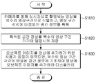
본 개시의 일 실시 예에 따른 전자 장치의 제어 방법은, 카메라를 통해 실시간으로 촬영되는 영상을 복수의 영상 구간으로 식별하고, 영상 구간 각각에 대응되는 공간 정보를 획득한다(S1610).In the control method of the electronic device according to an embodiment of the present disclosure, an image photographed in real time through a camera is identified as a plurality of image sections, and spatial information corresponding to each of the video sections is obtained (S1610 ).
이어서, 획득된 공간 정보를 복수의 영상 구간 각각에 맵핑시켜 저장한다(S1620).Subsequently, the obtained spatial information is mapped to each of a plurality of image sections and stored (S1620).
이어서, 가상 오브젝트 이미지를 영상에 추가하기 위한 사용자 명령이 입력되면, 복수의 영상 구간 각각에 맵핑된 공간 정보에 기초하여 영상에 가상 오브젝트 이미지를 추가하여 디스플레이한다(S1630).Subsequently, when a user command for adding the virtual object image to the image is input, the virtual object image is added to the image based on the spatial information mapped to each of the plurality of image sections and displayed (S1630).
여기서, 저장하는 S1620 단계는, 복수의 영상 구간 각각에서 평면 공간에 대한 정보 및 카메라의 뷰 방향 정보를 획득하는 단계 및 평면 공간에 대한 정보 및 뷰 방향 정보를 공간 정보로 저장하는 단계를 포함할 수 있다. 디스플레이하는 S1630 단계는, 복수의 영상 구간 각각에서 평면 공간에 대한 정보에 기초하여 가상 오브젝트 이미지를 추가하기 위한 위치 정보를 획득하는 단계, 카메라의 뷰 방향 정보에 대응되는 형상의 가상 오브젝트 이미지를 획득하는 단계 및 위치 정보에 기초하여 획득된 가상 오브젝트 이미지를 대응되는 영상 구간에 추가하여 디스플레이하는 단계를 포함한다.Here, the step of storing S1620 may include acquiring information about a plane space and view direction information of a camera in each of a plurality of image sections, and storing information about the plane space and view direction information as spatial information. have. In operation S1630 for displaying, obtaining location information for adding a virtual object image based on information on a plane space in each of the plurality of image sections, and obtaining a virtual object image having a shape corresponding to the view direction information of the camera And adding and displaying the virtual object image obtained based on the step and location information to a corresponding video section.
본 개시의 일 실시 예에 따른, 카메라의 뷰 방향 정보를 획득하는 단계는, 전자 장치의 가속도 센서 또는 자이로 센서 중 적어도 하나를 통해 획득된 카메라의 위치 또는 자세 중 적어도 하나에 대한 정보를 뷰 방향 정보로 획득할 수 있다.According to an embodiment of the present disclosure, the step of acquiring the view direction information of the camera may include information on at least one of the position or posture of the camera obtained through at least one of the acceleration sensor or the gyro sensor of the electronic device. Can be obtained by
본 개시의 일 실시 예에 따른, 디스플레이하는 S1630 단계는, 복수의 영상 구간 중 적어도 하나의 구간에서 획득된 공간 정보에 기초하여 가상 오브젝트 이미지를 추가하기 위한 위치 정보가 복수 개 획득되면, 이전에 가상 오브젝트 이미지를 영상에 추가한 히스토리 정보에 기초하여 복수 개의 위치 정보 중 하나를 식별하는 단계를 포함할 수 있다.According to an embodiment of the present disclosure, in operation S1630 of displaying, if a plurality of location information for adding a virtual object image is obtained based on spatial information obtained in at least one section of a plurality of image sections, previously It may include the step of identifying one of the plurality of location information based on the history information added to the object image.
본 개시의 일 실시 예에 따른 제어 방법은 복수의 영상 구간 각각에서 획득된 뷰 방향 정보에 기초하여 복수의 영상 구간의 순서가 재배열된 영상을 획득하는 단계를 포함하고, 디스플레이하는 S1630 단계는, 획득된 영상의 재생 시점을 조정하기 위한 네비게이션 바를 획득된 영상과 함께 디스플레이할 수 있다.The control method according to an embodiment of the present disclosure includes obtaining an image in which an order of a plurality of image sections is rearranged based on view direction information obtained from each of the plurality of image sections, and the displaying step S1630 includes: A navigation bar for adjusting a playback time of the acquired image may be displayed together with the acquired image.
여기서, 순서가 재배열된 영상을 획득하는 단계는, 뷰 방향 정보에 기초하여 카메라의 뷰 방향이 제1 방향에서 제2 방향으로 이동되도록 복수의 영상 구간의 순서를 재배열할 수 있다.Here, in the step of obtaining the rearranged images, the order of the plurality of image sections may be rearranged such that the view direction of the camera is moved from the first direction to the second direction based on the view direction information.
본 개시의 일 실시 예에 따른 제어 방법은 복수의 영상 구간 및 복수의 영상 구간 각각에 맵핑된 공간 정보를 외부 장치로 전송하는 단계를 포함할 수 있다.The control method according to an embodiment of the present disclosure may include transmitting spatial information mapped to each of the plurality of image sections and the plurality of image sections to an external device.
또한, 디스플레이하는 S1630 단계는, 외부 장치로부터 복수의 영상 구간 및 복수의 영상 구간 각각에 맵핑된 공간 정보에 기초하여 타 가상 오브젝트 이미지가 추가된 영상이 수신되면, 가상 오브젝트 이미지를 수신된 영상에 포함된 타 가상 오브젝트 이미지로 대체하여 디스플레이하는 단계를 포함할 수 있다.In addition, in operation S1630 of displaying, when an image to which another virtual object image is added is received based on spatial information mapped to each of a plurality of image sections and a plurality of image sections from an external device, the virtual object image is included in the received image. It may include the step of displaying by replacing with the other virtual object image.
본 개시의 일 실시 예에 따른 가상 오브젝트 이미지는, 3D 가상 오브젝트 이미지를 상이한 방향 또는 상이한 거리에서 캡쳐한 복수의 가상 오브젝트 이미지 중 공간 정보에 대응되는 가상 오브젝트 이미지일 수 있다.The virtual object image according to an embodiment of the present disclosure may be a virtual object image corresponding to spatial information among a plurality of virtual object images captured in different directions or different distances.
여기서, 디스플레이하는 S1630 단계는, 영상에 포함된 가상 오브젝트 이미지의 위치 변경 또는 회전 중 적어도 하나를 위한 사용자 명령이 입력되면, 사용자 명령에 대응되는 방향 정보 또는 거리 정보 중 적어도 하나를 획득하는 단계 및 획득된 정보에 기초하여 복수의 가상 오브젝트 이미지 중 사용자 명령에 대응되는 가상 오브젝트 이미지를 획득하여 디스플레이하는 단계를 포함할 수 있다.Here, in step S1630 of displaying, when a user command for at least one of position change or rotation of the virtual object image included in the image is input, obtaining and obtaining at least one of direction information or distance information corresponding to the user command And acquiring and displaying a virtual object image corresponding to a user command among the plurality of virtual object images based on the displayed information.
본 개시의 일 실시 예에 따른 저장하는 S1620 단계는, 복수의 영상 구간 각각에 포함된 오브젝트에 대한 정보를 획득하여 공간 정보로 저장하는 단계를 포함할 수 있고, 디스플레이하는 S1630 단계는, 복수의 영상 구간 각각에서 오브젝트에 대한 정보에 기초하여 오브젝트 상의 일 영역에 가상 오브젝트 이미지를 추가하기 위한 위치 정보를 획득하는 단계, 카메라의 뷰 방향 정보에 대응되는 형상의 가상 오브젝트 이미지를 획득하는 단계, 위치 정보에 기초하여 획득된 가상 오브젝트 이미지를 대응되는 영상 구간에 추가하여 디스플레이하는 단계를 포함할 수 있다.The storing step S1620 according to an embodiment of the present disclosure may include the step of acquiring information about an object included in each of the plurality of image sections and storing the information as spatial information. Obtaining location information for adding a virtual object image to an area on the object based on information about the object in each section, obtaining a virtual object image of a shape corresponding to the view direction information of the camera, and location information And adding and displaying the virtual object image obtained based on the corresponding image section.
본 개시의 일 실시 예에 따른 저장하는 S1620 단계는, 복수의 영상 구간 각각에 포함된 오브젝트에 대한 정보 및 오브젝트가 위치한 공간의 형태 정보를 획득하여 공간 정보로 저장하는 단계를 포함할 수 있고, 디스플레이하는 S1630 단계는, 오브젝트를 가상 오브젝트로 대체하기 위한 사용자 명령이 입력되면, 오브젝트에 대한 정보 및 공간의 형태 정보에 기초하여 가상 오브젝트 이미지를 오브젝트에 오버랩시켜 디스플레이할 수 있다.The storing step S1620 according to an embodiment of the present disclosure may include the step of acquiring information about an object included in each of a plurality of image sections and shape information of a space in which the object is located, and storing the information as spatial information. In operation S1630, when a user command for replacing an object with a virtual object is input, the virtual object image may be overlapped and displayed on the object based on information about the object and shape information of the space.
여기서, 일 실시 예에 따른 제어 방법은 영상을 학습 네트워크 모델에 적용하여 복수의 영상 구간 각각에 포함된 오브젝트에 대한 정보를 획득하는 단계를 포함하고, 오브젝트에 대한 정보는, 오브젝트의 종류, 형태, 크기 또는 위치 중 적어도 하나를 포함할 수 있다.Here, the control method according to an embodiment includes acquiring information on an object included in each of a plurality of image sections by applying an image to a learning network model, and the information on the object includes: the type, shape, and type of the object. It may include at least one of a size or a position.
또한, 디스플레이하는 S1630 단계는, 가상 오브젝트 이미지 상의 일 영역에 타 가상 오브젝트 이미지를 추가하기 위한 사용자 명령이 입력되면, 가상 오브젝트 이미지에 대한 정보에 기초하여 타 가상 오브젝트 이미지를 가상 오브젝트 이미지 상에 적층되는 형태로 디스플레이되도록 디스플레이를 제어할 수 있다.본 개시의 일 실시 예에 따른 제어하는 방법은 가상 오브젝트 이미지를 제거하기 위한 명령이 입력되면, 가상 오브젝트 이미지를 제거하는 단계 및 타 가상 오브젝트 이미지를 가상 오브젝트 이미지가 제거된 위치에 디스플레이하는 단계를 포함할 수 있다.In addition, in step S1630 of displaying, when a user command for adding another virtual object image to a region on the virtual object image is input, the other virtual object image is stacked on the virtual object image based on the information on the virtual object image. The display may be controlled to be displayed in a form. According to an exemplary embodiment of the present disclosure, when a command for removing a virtual object image is input, removing the virtual object image and other virtual object images as virtual objects And displaying the image at the removed location.
한편, 상술한 본 개시의 다양한 실시 예들에 따른 방법들은, 기존 전자 장치에 설치 가능한 어플리케이션 형태로 구현될 수 있다. Meanwhile, the methods according to various embodiments of the present disclosure described above may be implemented in an application form that can be installed in an existing electronic device.
또한, 상술한 본 개시의 다양한 실시 예들에 따른 방법들은, 기존 전자 장치에 대한 소프트웨어 업그레이드, 또는 하드웨어 업그레이드 만으로도 구현될 수 있다. Further, the methods according to various embodiments of the present disclosure described above may be implemented only by software upgrade or hardware upgrade of an existing electronic device.
또한, 상술한 본 개시의 다양한 실시 예들은 전자 장치에 구비된 임베디드 서버, 또는 전자 장치 및 디스플레이 장치 중 적어도 하나의 외부 서버를 통해 수행되는 것도 가능하다. In addition, various embodiments of the present disclosure described above may be performed through an embedded server provided in an electronic device or an external server of at least one of an electronic device and a display device.
한편, 본 개시의 일시 예에 따르면, 이상에서 설명된 다양한 실시 예들은 기기(machine)(예: 컴퓨터)로 읽을 수 있는 저장 매체(machine-readable storage media에 저장된 명령어를 포함하는 소프트웨어로 구현될 수 있다. 기기는, 저장 매체로부터 저장된 명령어를 호출하고, 호출된 명령어에 따라 동작이 가능한 장치로서, 개시된 실시 예들에 따른 전자 장치(예: 전자 장치(A))를 포함할 수 있다. 명령이 프로세서에 의해 실행될 경우, 프로세서가 직접, 또는 프로세서의 제어 하에 다른 구성요소들을 이용하여 명령에 해당하는 기능을 수행할 수 있다. 명령은 컴파일러 또는 인터프리터에 의해 생성 또는 실행되는 코드를 포함할 수 있다. 기기로 읽을 수 있는 저장매체는, 비일시적(non-transitory) 저장매체의 형태로 제공될 수 있다. 여기서, '비일시적'은 저장매체가 신호(signal)를 포함하지 않으며 실재(tangible)한다는 것을 의미할 뿐 데이터가 저장매체에 반영구적 또는 임시적으로 저장됨을 구분하지 않는다.Meanwhile, according to the date and time example of the present disclosure, various embodiments described above may be implemented with software including instructions stored in a machine-readable storage media (machine). The device is a device that can call a stored command from a storage medium and is operable according to the called command, and may include an electronic device (eg, the electronic device A) according to the disclosed embodiments. When executed by the processor, the processor may perform functions corresponding to the instructions directly or using other components under the control of the processor, which may include code generated or executed by a compiler or interpreter. A storage medium that can be read as can be provided in the form of a non-transitory storage medium, where'non-transitory' means that the storage medium does not contain a signal and is tangible. It does not distinguish between data being stored semi-permanently or temporarily on the storage medium.
또한, 본 개시의 일 실시 예에 따르면, 이상에서 설명된 다양한 실시 예들에 따른 방법은 컴퓨터 프로그램 제품(computer program product)에 포함되어 제공될 수 있다. 컴퓨터 프로그램 제품은 상품으로서 판매자 및 구매자 간에 거래될 수 있다. 컴퓨터 프로그램 제품은 기기로 읽을 수 있는 저장 매체(예: compact disc read only memory (CD-ROM))의 형태로, 또는 어플리케이션 스토어(예: 플레이 스토어TM)를 통해 온라인으로 배포될 수 있다. 온라인 배포의 경우에, 컴퓨터 프로그램 제품의 적어도 일부는 제조사의 서버, 어플리케이션 스토어의 서버, 또는 중계 서버의 메모리와 같은 저장 매체에 적어도 일시 저장되거나, 임시적으로 생성될 수 있다.Further, according to an embodiment of the present disclosure, a method according to various embodiments described above may be provided as being included in a computer program product. Computer program products are commodities that can be traded between sellers and buyers. The computer program product may be distributed online in the form of a device-readable storage medium (eg compact disc read only memory (CD-ROM)) or through an application store (eg Play StoreTM). In the case of online distribution, at least a portion of the computer program product may be stored at least temporarily on a storage medium such as a memory of a manufacturer's server, an application store's server, or a relay server, or may be temporarily generated.
또한, 상술한 다양한 실시 예들에 따른 구성 요소(예: 모듈 또는 프로그램) 각각은 단수 또는 복수의 개체로 구성될 수 있으며, 전술한 해당 서브 구성 요소들 중 일부 서브 구성 요소가 생략되거나, 또는 다른 서브 구성 요소가 다양한 실시 예에 더 포함될 수 있다. 대체적으로 또는 추가적으로, 일부 구성 요소들(예: 모듈 또는 프로그램)은 하나의 개체로 통합되어, 통합되기 이전의 각각의 해당 구성 요소에 의해 수행되는 기능을 동일 또는 유사하게 수행할 수 있다. 다양한 실시 예들에 따른, 모듈, 프로그램 또는 다른 구성 요소에 의해 수행되는 동작들은 순차적, 병렬적, 반복적 또는 휴리스틱하게 실행되거나, 적어도 일부 동작이 다른 순서로 실행되거나, 생략되거나, 또는 다른 동작이 추가될 수 있다.In addition, each of the components (for example, a module or a program) according to various embodiments described above may be composed of a singular or a plurality of entities, and some of the aforementioned sub-components may be omitted, or other sub-components may be omitted. Components may be further included in various embodiments. Alternatively or additionally, some components (eg, modules or programs) may be integrated into one entity, performing the same or similar functions performed by each corresponding component prior to integration. According to various embodiments, operations performed by a module, program, or other component may be sequentially, parallelly, repeatedly, or heuristically executed, at least some operations may be executed in a different order, omitted, or other operations may be added. You can.
이상에서는 본 개시의 바람직한 실시 예에 대하여 도시하고 설명하였지만, 본 개시는 상술한 특정의 실시 예에 한정되지 아니하며, 청구범위에서 청구하는 본 개시의 요지를 벗어남이 없이 당해 개시에 속하는 기술분야에서 통상의 지식을 가진 자에 의해 다양한 변형실시가 가능한 것은 물론이고, 이러한 변형실시들은 본 개시의 기술적 사상이나 전망으로부터 개별적으로 이해되어져서는 안될 것이다.Although the preferred embodiments of the present disclosure have been described and described above, the present disclosure is not limited to the specific embodiments described above, and is generally limited in the technical field belonging to the present disclosure without departing from the gist of the present disclosure claimed in the claims. Of course, various modifications can be implemented by a person who has knowledge of, and these modifications should not be individually understood from the technical idea or prospect of the present disclosure.
100: 전자 장치
110: 디스플레이
120: 카메라
130: 메모리
140: 프로세서100: electronic device 110: display
120: camera 130: memory
140: processor
Claims (20)
카메라;
메모리; 및
상기 카메라를 통해 실시간으로 촬영되는 영상을 복수의 영상 구간으로 식별하고, 상기 영상 구간 각각에 대응되는 공간 정보를 획득하고,
상기 획득된 공간 정보를 상기 복수의 영상 구간 각각에 맵핑시켜 상기 메모리에 저장하고,
가상 오브젝트 이미지를 상기 영상에 추가하기 위한 사용자 명령이 입력되면, 상기 복수의 영상 구간 각각에 맵핑된 공간 정보에 기초하여 상기 가상 오브젝트 이미지를 상기 영상에 추가하여 디스플레이하도록 상기 디스플레이를 제어하는 프로세서;를 포함하는 전자 장치. display;
camera;
Memory; And
The images captured in real time through the camera are identified as a plurality of image sections, and spatial information corresponding to each of the image sections is acquired,
The obtained spatial information is mapped to each of the plurality of image sections and stored in the memory,
A processor for controlling the display to display the virtual object image by adding the virtual object image to the image based on spatial information mapped to each of the plurality of image sections when a user command for adding the virtual object image to the image is input; Electronic device comprising.
상기 프로세서는,
상기 복수의 영상 구간 각각에서 평면 공간에 대한 정보 및 상기 카메라의 뷰 방향 정보를 획득하여 상기 공간 정보로 저장하며, 상기 복수의 영상 구간 각각에서 상기 평면 공간에 대한 정보에 기초하여 상기 가상 오브젝트 이미지를 추가하기 위한 위치 정보를 획득하고, 상기 카메라의 뷰 방향 정보에 대응되는 형상의 가상 오브젝트 이미지를 획득하고, 상기 위치 정보에 기초하여 상기 획득된 가상 오브젝트 이미지를 대응되는 영상 구간에 추가하여 디스플레이하도록 상기 디스플레이를 제어하는, 전자 장치.According to claim 1,
The processor,
In each of the plurality of image sections, information about a plane space and view direction information of the camera are obtained and stored as the space information, and the virtual object image is based on information about the plane space in each of the plurality of image sections. Acquiring location information for adding, acquiring a virtual object image having a shape corresponding to the view direction information of the camera, and adding the obtained virtual object image to a corresponding video section based on the location information to display An electronic device that controls a display.
상기 프로세서는,
가속도 센서 또는 자이로 센서 중 적어도 하나를 통해 획득된 상기 카메라의 위치 또는 자세 중 적어도 하나에 대한 정보를 상기 카메라의 뷰 방향 정보로 저장하는, 전자 장치.According to claim 2,
The processor,
An electronic device that stores information on at least one of the position or posture of the camera obtained through at least one of an acceleration sensor or a gyro sensor as view direction information of the camera.
상기 프로세서는,
상기 복수의 영상 구간 중 적어도 하나의 구간에서 상기 획득된 공간 정보에 기초하여 상기 가상 오브젝트 이미지를 추가하기 위한 위치 정보가 복수 개 획득되면, 이전에 가상 오브젝트 이미지를 상기 영상에 추가한 히스토리 정보에 기초하여 상기 복수 개의 위치 정보 중 하나를 식별하는, 전자 장치.According to claim 1,
The processor,
When a plurality of location information for adding the virtual object image is obtained based on the obtained spatial information in at least one section of the plurality of image sections, based on history information that previously added the virtual object image to the image To identify one of the plurality of location information.
상기 프로세서는,
상기 복수의 영상 구간 각각에서 획득된 상기 카메라의 뷰 방향 정보에 기초하여 상기 복수의 영상 구간의 순서가 재배열된 영상을 획득하고,
상기 획득된 영상의 재생 시점을 조정하기 위한 네비게이션 바를 상기 획득된 영상과 함께 디스플레이하도록 상기 디스플레이를 제어하는, 전자 장치.According to claim 1,
The processor,
Obtain an image in which the order of the plurality of image sections is rearranged based on view direction information of the camera obtained in each of the plurality of image sections,
An electronic device that controls the display to display a navigation bar for adjusting a playback time point of the acquired image together with the acquired image.
상기 프로세서는,
상기 카메라의 뷰 방향 정보에 기초하여 상기 카메라의 뷰 방향이 제1 방향에서 제2 방향으로 이동되도록 상기 복수의 영상 구간의 순서를 재배열하는, 전자 장치.The method of claim 5,
The processor,
And rearranging the order of the plurality of image sections so that the view direction of the camera is moved from a first direction to a second direction based on the view direction information of the camera.
통신부;를 포함하며,
상기 프로세서는,
상기 메모리에 저장된 상기 복수의 영상 구간 및 상기 복수의 영상 구간 각각에 맵핑된 공간 정보를 외부 장치로 전송하도록 상기 통신부를 제어하는, 전자 장치.According to claim 1,
Communication unit; includes,
The processor,
An electronic device that controls the communication unit to transmit spatial information mapped to each of the plurality of image sections and each of the plurality of image sections stored in the memory to an external device.
상기 프로세서는,
상기 외부 장치로부터 상기 복수의 영상 구간 및 상기 복수의 영상 구간 각각에 맵핑된 공간 정보에 기초하여 타 가상 오브젝트 이미지가 추가된 영상이 수신되면, 상기 가상 오브젝트 이미지를 상기 수신된 영상에 포함된 상기 타 가상 오브젝트 이미지로 대체하여 디스플레이하도록 상기 디스플레이를 제어하는, 전자 장치.The method of claim 7,
The processor,
When an image to which another virtual object image is added is received based on spatial information mapped to each of the plurality of image sections and each of the plurality of image sections, the virtual object image is included in the received image from the external device. And controlling the display to display a virtual object image.
상기 가상 오브젝트 이미지는,
3D 오브젝트 이미지를 상이한 방향 또는 상이한 거리에서 캡쳐한 복수의 가상 오브젝트 이미지 중 상기 공간 정보에 대응되는 가상 오브젝트 이미지인, 전자 장치.According to claim 1,
The virtual object image,
An electronic device that is a virtual object image corresponding to the spatial information among a plurality of virtual object images captured from different directions or different distances.
상기 프로세서는,
상기 디스플레이되는 영상에 포함된 상기 가상 오브젝트 이미지의 위치 변경 또는 회전 중 적어도 하나를 위한 사용자 명령이 입력되면, 상기 사용자 명령에 대응되는 방향 정보 또는 거리 정보 중 적어도 하나를 획득하고, 상기 획득된 정보에 기초하여 상기 복수의 가상 오브젝트 이미지 중 상기 사용자 명령에 대응되는 가상 오브젝트 이미지를 획득하여 디스플레이하도록 상기 디스플레이를 제어하는, 전자 장치.The method of claim 9,
The processor,
When a user command for at least one of changing or rotating a position of the virtual object image included in the displayed image is input, at least one of direction information or distance information corresponding to the user command is acquired, and the acquired information is An electronic device that controls the display to obtain and display a virtual object image corresponding to the user command among the plurality of virtual object images based on the image.
상기 프로세서는,
상기 복수의 영상 구간 각각에 포함된 오브젝트에 대한 정보를 획득하여 상기 공간 정보로 저장하며,
상기 복수의 영상 구간 각각에서 상기 오브젝트에 대한 정보에 기초하여 상기 오브젝트 상의 일 영역에 상기 가상 오브젝트 이미지를 추가하기 위한 위치 정보를 획득하고,
상기 카메라의 뷰 방향 정보에 대응되는 형상의 상기 가상 오브젝트 이미지를 획득하고, 상기 위치 정보에 기초하여 상기 획득된 가상 오브젝트 이미지를 대응되는 영상 구간에 추가하여 디스플레이하도록 상기 디스플레이를 제어하는, 전자 장치.According to claim 1,
The processor,
Acquire information about an object included in each of the plurality of image sections and store it as the spatial information,
Acquire location information for adding the virtual object image to a region on the object based on the information on the object in each of the plurality of image sections,
An electronic device for acquiring the virtual object image having a shape corresponding to the view direction information of the camera, and controlling the display to add and display the obtained virtual object image to a corresponding image section based on the location information.
상기 프로세서는,
상기 복수의 영상 구간 각각에 포함된 오브젝트에 대한 정보 및 상기 오브젝트가 위치한 공간의 형태 정보를 획득하여 상기 공간 정보로 저장하며,
상기 오브젝트를 상기 가상 오브젝트로 대체하기 위한 사용자 명령이 입력되면, 상기 오브젝트에 대한 정보 및 상기 공간의 형태 정보에 기초하여 상기 가상 오브젝트 이미지를 상기 오브젝트에 오버랩시켜 디스플레이하는, 전자 장치.According to claim 1,
The processor,
Acquire information about an object included in each of the plurality of image sections and shape information of a space in which the object is located, and store it as the spatial information,
When a user command for replacing the object with the virtual object is input, the electronic device overlaps and displays the virtual object image on the basis of the information on the object and the shape information of the space.
상기 프로세서는,
상기 영상을 학습 네트워크 모델에 적용하여 상기 복수의 영상 구간 각각에 포함된 오브젝트에 대한 정보를 획득하고,
상기 오브젝트에 대한 정보는,
상기 오브젝트의 종류, 형태, 크기 또는 위치 중 적어도 하나를 포함하는, 전자 장치.According to claim 1,
The processor,
Applying the image to a learning network model to obtain information about an object included in each of the plurality of image sections,
Information about the object,
An electronic device including at least one of the type, shape, size, or location of the object.
상기 프로세서는,
상기 가상 오브젝트 이미지 상의 일 영역에 타 가상 오브젝트 이미지를 추가하기 위한 사용자 명령이 입력되면, 상기 가상 오브젝트 이미지에 대한 정보에 기초하여 상기 타 가상 오브젝트 이미지를 상기 가상 오브젝트 이미지 상에 적층되는 형태로 디스플레이되도록 상기 디스플레이를 제어하는, 전자 장치.According to claim 1,
The processor,
When a user command for adding another virtual object image is input to a region on the virtual object image, the other virtual object image is displayed in a stacked form on the virtual object image based on information on the virtual object image. An electronic device that controls the display.
상기 프로세서는,
상기 가상 오브젝트 이미지를 제거하기 위한 명령이 입력되면, 상기 가상 오브젝트 이미지를 제거하고, 상기 타 가상 오브젝트 이미지를 상기 가상 오브젝트 이미지가 제거된 위치에 디스플레이하도록 상기 디스플레이를 제어하는, 전자 장치.The method of claim 14,
The processor,
When a command for removing the virtual object image is input, the electronic device controls the display to remove the virtual object image and display the other virtual object image at a location where the virtual object image is removed.
카메라를 통해 실시간으로 촬영되는 영상을 복수의 영상 구간으로 식별하고, 상기 영상 구간 각각에 대응되는 공간 정보를 획득하는 단계;
상기 획득된 공간 정보를 상기 복수의 영상 구간 각각에 맵핑시켜 저장하는 단계; 및
가상 오브젝트 이미지를 상기 영상에 추가하기 위한 사용자 명령이 입력되면, 상기 복수의 영상 구간 각각에 맵핑된 공간 정보에 기초하여 상기 영상에 상기 가상 오브젝트 이미지를 추가하여 디스플레이하는 단계;를 포함하는 제어 방법.In the control method of the electronic device,
Identifying an image photographed in real time through a camera as a plurality of image sections, and obtaining spatial information corresponding to each of the video sections;
Storing the obtained spatial information by mapping each of the plurality of image sections; And
And when a user command for adding a virtual object image to the image is input, adding and displaying the virtual object image on the image based on spatial information mapped to each of the plurality of image sections.
상기 저장하는 단계는,
상기 복수의 영상 구간 각각에서 평면 공간에 대한 정보 및 상기 카메라의 뷰 방향 정보를 획득하는 단계; 및
상기 평면 공간에 대한 정보 및 상기 뷰 방향 정보를 상기 공간 정보로 저장하는 단계;를 포함하고,
상기 디스플레이하는 단계는,
상기 복수의 영상 구간 각각에서 상기 평면 공간에 대한 정보에 기초하여 상기 가상 오브젝트 이미지를 추가하기 위한 위치 정보를 획득하는 단계;
상기 카메라의 뷰 방향 정보에 대응되는 형상의 가상 오브젝트 이미지를 획득하는 단계; 및
상기 위치 정보에 기초하여 상기 획득된 가상 오브젝트 이미지를 대응되는 영상 구간에 추가하여 디스플레이하는 단계;를 포함하는, 제어 방법.The method of claim 16,
The storing step,
Acquiring information about a plane space and view direction information of the camera in each of the plurality of image sections; And
And storing information on the planar space and the view direction information as the spatial information.
The displaying step,
Acquiring location information for adding the virtual object image based on information on the plane space in each of the plurality of image sections;
Obtaining a virtual object image having a shape corresponding to the view direction information of the camera; And
And adding and displaying the obtained virtual object image to a corresponding video section based on the location information.
상기 획득하는 단계는,
상기 전자 장치의 가속도 센서 또는 자이로 센서 중 적어도 하나를 통해 획득된 상기 카메라의 위치 또는 자세 중 적어도 하나에 대한 정보를 상기 뷰 방향 정보로 획득하는, 제어 방법.The method of claim 17,
The obtaining step,
A control method for acquiring information on at least one of a position or a posture of the camera obtained through at least one of an acceleration sensor or a gyro sensor of the electronic device as the view direction information.
상기 디스플레이하는 단계는,
상기 복수의 영상 구간 중 적어도 하나의 구간에서 상기 획득된 공간 정보에 기초하여 상기 가상 오브젝트 이미지를 추가하기 위한 위치 정보가 복수 개 획득되면, 이전에 가상 오브젝트 이미지를 상기 영상에 추가한 히스토리 정보에 기초하여 상기 복수 개의 위치 정보 중 하나를 식별하는 단계;를 포함하는, 제어 방법.The method of claim 16,
The displaying step,
When a plurality of location information for adding the virtual object image is obtained based on the obtained spatial information in at least one section of the plurality of image sections, based on history information that previously added the virtual object image to the image And identifying one of the plurality of location information.
상기 복수의 영상 구간 각각에서 획득된 상기 뷰 방향 정보에 기초하여 상기 복수의 영상 구간의 순서가 재배열된 영상을 획득하는 단계;를 포함하고,
상기 디스플레이하는 단계는,
상기 획득된 영상의 재생 시점을 조정하기 위한 네비게이션 바를 상기 획득된 영상과 함께 디스플레이하는, 제어 방법.
The method of claim 16,
And obtaining an image in which the order of the plurality of image sections is rearranged based on the view direction information obtained in each of the plurality of image sections.
The displaying step,
A control method for displaying a navigation bar for adjusting a reproduction time point of the acquired image together with the acquired image.
Priority Applications (5)
| Application Number | Priority Date | Filing Date | Title |
|---|---|---|---|
| KR1020190065591A KR102640581B1 (en) | 2018-11-23 | 2019-06-03 | Electronic apparatus and control method thereof |
| EP19888021.3A EP3863277A4 (en) | 2018-11-23 | 2019-08-23 | Electronic device and control method thereof |
| PCT/KR2019/010783 WO2020105847A1 (en) | 2018-11-23 | 2019-08-23 | Electronic device and control method thereof |
| CN201980076820.XA CN113170058B (en) | 2018-11-23 | 2019-08-23 | Electronic apparatus and control method thereof |
| US17/286,879 US11763535B2 (en) | 2018-11-23 | 2019-08-23 | Electronic device and control method thereof |
Applications Claiming Priority (2)
| Application Number | Priority Date | Filing Date | Title |
|---|---|---|---|
| KR1020180146671 | 2018-11-23 | ||
| KR20180146671 | 2018-11-23 |
Publications (1)
| Publication Number | Publication Date |
|---|---|
| KR20200061279A true KR20200061279A (en) | 2020-06-02 |
Family
ID=71090947
Family Applications (1)
| Application Number | Title | Priority Date | Filing Date |
|---|---|---|---|
| KR1020190036882A KR20200061279A (en) | 2018-11-23 | 2019-03-29 | Electronic apparatus and control method thereof |
Country Status (3)
| Country | Link |
|---|---|
| US (1) | US11763535B2 (en) |
| KR (1) | KR20200061279A (en) |
| CN (1) | CN113170058B (en) |
Cited By (2)
| Publication number | Priority date | Publication date | Assignee | Title |
|---|---|---|---|---|
| US20210360155A1 (en) * | 2017-04-24 | 2021-11-18 | Intel Corporation | Object pre-encoding for 360-degree view for optimal quality and latency |
| WO2021261619A1 (en) * | 2020-06-24 | 2021-12-30 | 삼성전자 주식회사 | Electronic device for detecting plane in image and operation method thereof |
Families Citing this family (5)
| Publication number | Priority date | Publication date | Assignee | Title |
|---|---|---|---|---|
| US11682056B2 (en) * | 2020-03-27 | 2023-06-20 | Savor Brands Inc. | Systems and methods for consumer integration into a point-of-sale system |
| WO2022081717A1 (en) * | 2020-10-13 | 2022-04-21 | Flyreel, Inc. | Generating measurements of physical structures and environments through automated analysis of sensor data |
| US11170582B1 (en) * | 2021-05-04 | 2021-11-09 | Dapper Labs Inc. | System and method for creating, managing, and displaying limited edition, serialized 3D digital collectibles with visual indicators of rarity classifications |
| US11943565B2 (en) * | 2021-07-12 | 2024-03-26 | Milestone Systems A/S | Computer implemented method and apparatus for operating a video management system |
| CN115225818B (en) * | 2022-07-13 | 2024-05-21 | 北京有竹居网络技术有限公司 | Method, apparatus, device and storage medium for configuring device |
Family Cites Families (17)
| Publication number | Priority date | Publication date | Assignee | Title |
|---|---|---|---|---|
| JP4153761B2 (en) | 2002-09-19 | 2008-09-24 | 成典 田中 | 3D model space generation device, 3D model space generation method, and 3D model space generation program |
| EP3247110B1 (en) | 2005-07-18 | 2018-05-16 | Thomson Licensing | Method and device for handling multiple video streams using metadata |
| DE102007045835B4 (en) * | 2007-09-25 | 2012-12-20 | Metaio Gmbh | Method and device for displaying a virtual object in a real environment |
| KR101390811B1 (en) | 2007-10-04 | 2014-05-26 | 삼성전자주식회사 | Method and apparatus for receiving multiview camera parameters for stereoscopic image, and method and apparatus for transmitting multiview camera parameters for stereoscopic image |
| US8218855B2 (en) | 2007-10-04 | 2012-07-10 | Samsung Electronics Co., Ltd. | Method and apparatus for receiving multiview camera parameters for stereoscopic image, and method and apparatus for transmitting multiview camera parameters for stereoscopic image |
| JP5524965B2 (en) | 2008-08-12 | 2014-06-18 | グーグル インコーポレイテッド | Inspection in geographic information system |
| KR101971948B1 (en) | 2011-07-28 | 2019-04-24 | 삼성전자주식회사 | Marker-less augmented reality system using plane feature and method thereof |
| US8606645B1 (en) | 2012-02-02 | 2013-12-10 | SeeMore Interactive, Inc. | Method, medium, and system for an augmented reality retail application |
| KR20130131179A (en) | 2012-05-23 | 2013-12-03 | 대전보건대학 산학협력단 | Cyber model house system using metaverse |
| US8954853B2 (en) * | 2012-09-06 | 2015-02-10 | Robotic Research, Llc | Method and system for visualization enhancement for situational awareness |
| JP6476658B2 (en) | 2013-09-11 | 2019-03-06 | ソニー株式会社 | Image processing apparatus and method |
| KR20160033495A (en) | 2014-09-18 | 2016-03-28 | 서강대학교산학협력단 | Apparatus and method for arranging furniture using augmented reality |
| KR101952989B1 (en) | 2015-01-29 | 2019-02-28 | 전자부품연구원 | Virtual Contents Creation Method and System with Space Matching Scheme |
| KR20170015622A (en) * | 2015-07-29 | 2017-02-09 | 삼성전자주식회사 | User terminal apparatus and control method thereof |
| KR102559625B1 (en) | 2016-01-25 | 2023-07-26 | 삼성전자주식회사 | Method for Outputting Augmented Reality and Electronic Device supporting the same |
| GB2549723A (en) * | 2016-04-26 | 2017-11-01 | Nokia Technologies Oy | A system and method for video editing in a virtual reality enviroment |
| JP6196416B1 (en) | 2016-05-27 | 2017-09-13 | 楽天株式会社 | 3D model generation system, 3D model generation method, and program |
-
2019
- 2019-03-29 KR KR1020190036882A patent/KR20200061279A/en unknown
- 2019-08-23 CN CN201980076820.XA patent/CN113170058B/en active Active
- 2019-08-23 US US17/286,879 patent/US11763535B2/en active Active
Cited By (3)
| Publication number | Priority date | Publication date | Assignee | Title |
|---|---|---|---|---|
| US20210360155A1 (en) * | 2017-04-24 | 2021-11-18 | Intel Corporation | Object pre-encoding for 360-degree view for optimal quality and latency |
| US11800232B2 (en) * | 2017-04-24 | 2023-10-24 | Intel Corporation | Object pre-encoding for 360-degree view for optimal quality and latency |
| WO2021261619A1 (en) * | 2020-06-24 | 2021-12-30 | 삼성전자 주식회사 | Electronic device for detecting plane in image and operation method thereof |
Also Published As
| Publication number | Publication date |
|---|---|
| US11763535B2 (en) | 2023-09-19 |
| US20210335052A1 (en) | 2021-10-28 |
| CN113170058A (en) | 2021-07-23 |
| CN113170058B (en) | 2024-08-09 |
Similar Documents
| Publication | Publication Date | Title |
|---|---|---|
| US11763535B2 (en) | Electronic device and control method thereof | |
| US9898844B2 (en) | Augmented reality content adapted to changes in real world space geometry | |
| KR102640581B1 (en) | Electronic apparatus and control method thereof | |
| US20150185825A1 (en) | Assigning a virtual user interface to a physical object | |
| US11094105B2 (en) | Display apparatus and control method thereof | |
| US10802784B2 (en) | Transmission of data related to an indicator between a user terminal device and a head mounted display and method for controlling the transmission of data | |
| US11431909B2 (en) | Electronic device and operation method thereof | |
| US11763479B2 (en) | Automatic measurements based on object classification | |
| US11908042B2 (en) | Electronic apparatus and control method thereof | |
| CN111246264B (en) | Display apparatus and control method thereof | |
| US20150009216A1 (en) | Storage medium, image processing apparatus, image processing system and image processing method | |
| KR20210083016A (en) | Electronic apparatus and controlling method thereof | |
| US11867495B2 (en) | Electronic device for providing image data using augmented reality and control method for same | |
| KR20210015589A (en) | Electronic apparatus and control method thereof | |
| EP3863277A1 (en) | Electronic device and control method thereof | |
| KR102581146B1 (en) | Display apparatus and control method thereof | |
| KR20210157142A (en) | Electronic apparatus and controlling method thereof | |
| US11467798B2 (en) | Display apparatus for changing an advertisement area, server, electronic apparatus and control methods thereof | |
| KR20230137202A (en) | Display apparatus and control method thereof | |
| KR20240025418A (en) | Electronic apparatus transmitting a frame to a plurality of devices and control method thereof |