KR20200060201A - Camera module - Google Patents
Camera module Download PDFInfo
- Publication number
- KR20200060201A KR20200060201A KR1020190038839A KR20190038839A KR20200060201A KR 20200060201 A KR20200060201 A KR 20200060201A KR 1020190038839 A KR1020190038839 A KR 1020190038839A KR 20190038839 A KR20190038839 A KR 20190038839A KR 20200060201 A KR20200060201 A KR 20200060201A
- Authority
- KR
- South Korea
- Prior art keywords
- lens barrel
- movable lens
- magnet
- pair
- disposed
- Prior art date
Links
- 238000001514 detection method Methods 0.000 claims abstract description 9
- 230000003287 optical effect Effects 0.000 claims description 16
- 238000000034 method Methods 0.000 claims 5
- 230000008878 coupling Effects 0.000 description 5
- 238000010168 coupling process Methods 0.000 description 5
- 238000005859 coupling reaction Methods 0.000 description 5
- 230000008859 change Effects 0.000 description 3
- 238000003780 insertion Methods 0.000 description 3
- 230000037431 insertion Effects 0.000 description 3
- 230000001154 acute effect Effects 0.000 description 2
- 238000004519 manufacturing process Methods 0.000 description 2
- 238000010295 mobile communication Methods 0.000 description 2
- 230000008901 benefit Effects 0.000 description 1
- 239000000969 carrier Substances 0.000 description 1
- 230000007547 defect Effects 0.000 description 1
- 238000005516 engineering process Methods 0.000 description 1
- 230000007257 malfunction Effects 0.000 description 1
- 230000004044 response Effects 0.000 description 1
- 230000006641 stabilisation Effects 0.000 description 1
- 238000011105 stabilization Methods 0.000 description 1
- 239000013585 weight reducing agent Substances 0.000 description 1
Images


Classifications
-
- H—ELECTRICITY
- H04—ELECTRIC COMMUNICATION TECHNIQUE
- H04N—PICTORIAL COMMUNICATION, e.g. TELEVISION
- H04N23/00—Cameras or camera modules comprising electronic image sensors; Control thereof
- H04N23/50—Constructional details
- H04N23/55—Optical parts specially adapted for electronic image sensors; Mounting thereof
-
- H04N5/2254—
-
- G—PHYSICS
- G03—PHOTOGRAPHY; CINEMATOGRAPHY; ANALOGOUS TECHNIQUES USING WAVES OTHER THAN OPTICAL WAVES; ELECTROGRAPHY; HOLOGRAPHY
- G03B—APPARATUS OR ARRANGEMENTS FOR TAKING PHOTOGRAPHS OR FOR PROJECTING OR VIEWING THEM; APPARATUS OR ARRANGEMENTS EMPLOYING ANALOGOUS TECHNIQUES USING WAVES OTHER THAN OPTICAL WAVES; ACCESSORIES THEREFOR
- G03B13/00—Viewfinders; Focusing aids for cameras; Means for focusing for cameras; Autofocus systems for cameras
- G03B13/32—Means for focusing
- G03B13/34—Power focusing
- G03B13/36—Autofocus systems
-
- G—PHYSICS
- G03—PHOTOGRAPHY; CINEMATOGRAPHY; ANALOGOUS TECHNIQUES USING WAVES OTHER THAN OPTICAL WAVES; ELECTROGRAPHY; HOLOGRAPHY
- G03B—APPARATUS OR ARRANGEMENTS FOR TAKING PHOTOGRAPHS OR FOR PROJECTING OR VIEWING THEM; APPARATUS OR ARRANGEMENTS EMPLOYING ANALOGOUS TECHNIQUES USING WAVES OTHER THAN OPTICAL WAVES; ACCESSORIES THEREFOR
- G03B3/00—Focusing arrangements of general interest for cameras, projectors or printers
- G03B3/10—Power-operated focusing
-
- G—PHYSICS
- G03—PHOTOGRAPHY; CINEMATOGRAPHY; ANALOGOUS TECHNIQUES USING WAVES OTHER THAN OPTICAL WAVES; ELECTROGRAPHY; HOLOGRAPHY
- G03B—APPARATUS OR ARRANGEMENTS FOR TAKING PHOTOGRAPHS OR FOR PROJECTING OR VIEWING THEM; APPARATUS OR ARRANGEMENTS EMPLOYING ANALOGOUS TECHNIQUES USING WAVES OTHER THAN OPTICAL WAVES; ACCESSORIES THEREFOR
- G03B5/00—Adjustment of optical system relative to image or object surface other than for focusing
-
- H—ELECTRICITY
- H04—ELECTRIC COMMUNICATION TECHNIQUE
- H04N—PICTORIAL COMMUNICATION, e.g. TELEVISION
- H04N23/00—Cameras or camera modules comprising electronic image sensors; Control thereof
- H04N23/57—Mechanical or electrical details of cameras or camera modules specially adapted for being embedded in other devices
-
- H—ELECTRICITY
- H04—ELECTRIC COMMUNICATION TECHNIQUE
- H04N—PICTORIAL COMMUNICATION, e.g. TELEVISION
- H04N23/00—Cameras or camera modules comprising electronic image sensors; Control thereof
- H04N23/60—Control of cameras or camera modules
- H04N23/67—Focus control based on electronic image sensor signals
-
- H04N5/2257—
-
- H04N5/23212—
-
- G—PHYSICS
- G03—PHOTOGRAPHY; CINEMATOGRAPHY; ANALOGOUS TECHNIQUES USING WAVES OTHER THAN OPTICAL WAVES; ELECTROGRAPHY; HOLOGRAPHY
- G03B—APPARATUS OR ARRANGEMENTS FOR TAKING PHOTOGRAPHS OR FOR PROJECTING OR VIEWING THEM; APPARATUS OR ARRANGEMENTS EMPLOYING ANALOGOUS TECHNIQUES USING WAVES OTHER THAN OPTICAL WAVES; ACCESSORIES THEREFOR
- G03B2205/00—Adjustment of optical system relative to image or object surface other than for focusing
- G03B2205/0046—Movement of one or more optical elements for zooming
-
- G—PHYSICS
- G03—PHOTOGRAPHY; CINEMATOGRAPHY; ANALOGOUS TECHNIQUES USING WAVES OTHER THAN OPTICAL WAVES; ELECTROGRAPHY; HOLOGRAPHY
- G03B—APPARATUS OR ARRANGEMENTS FOR TAKING PHOTOGRAPHS OR FOR PROJECTING OR VIEWING THEM; APPARATUS OR ARRANGEMENTS EMPLOYING ANALOGOUS TECHNIQUES USING WAVES OTHER THAN OPTICAL WAVES; ACCESSORIES THEREFOR
- G03B2205/00—Adjustment of optical system relative to image or object surface other than for focusing
- G03B2205/0053—Driving means for the movement of one or more optical element
- G03B2205/0069—Driving means for the movement of one or more optical element using electromagnetic actuators, e.g. voice coils
Abstract
Description
본 발명은 카메라 모듈에 관한 것으로, 더 자세하게는 스마트폰과 같이 소형 디지털 기기에 설치되며 광학 줌과 자동초점 조절기능을 가지는 카메라 모듈에 관한 것이다.The present invention relates to a camera module, and more particularly, to a camera module that is installed in a small digital device such as a smartphone and has an optical zoom and auto focus adjustment function.
최근에는 디지털 카메라의 소형, 경량화 기술이 발달함에 따라, 광학 렌즈 및 카메라 소자가 장착된 이동통신 단말기가 보편화되고 있다.2. Description of the Related Art Recently, with the development of miniaturization and weight reduction technology for digital cameras, mobile communication terminals equipped with optical lenses and camera elements have become common.
여기서, 이동통신 단말기에 장착되는 카메라 모듈은 휴대용 기기의 크기가 커지지 않도록 초소형으로 제작됨은 물론, 광학 줌 기능, 자동초점 조절기능, 떨림 보정기능, 광량 조절기능 등과 같은 다양한 기능이 적용되고 있다.Here, the camera module mounted on the mobile communication terminal is manufactured in a compact form so that the size of the portable device is not increased, and various functions such as an optical zoom function, an automatic focus adjustment function, an image stabilization function, and a light amount adjustment function are applied.
이와 같은, 카메라 모듈은 내부에 다수의 렌즈가 수용되는 렌즈배럴과, 내측에 렌즈배럴이 삽입되고 광축 방향으로 이동 가능한 캐리어, 캐리어에 결합되어 캐리어를 지지하는 베이스, 및 베이스에 설치되어 캐리어를 베이스의 내측에서 일 측 또는 타 측으로 이동시키는 액추에이터 등으로 구성된다.As described above, the camera module is provided with a lens barrel in which a plurality of lenses are accommodated, a carrier in which a lens barrel is inserted and movable in the optical axis direction, a base coupled to a carrier to support the carrier, and a carrier installed on the base to base the carrier It consists of an actuator or the like to move from one side to the other side.
그런데 상기한 종래의 카메라 모듈은 한 개의 렌즈배럴을 이용하여 광학 줌 및 자동 초점 조절기능을 함께 수행해야함에 따라, 캐리어의 이동 시간이 길고, 이로 인해 각 기능의 구현이 오래 걸림은 물론, 캐리어의 잦은 이동에 따라 고장 또는 기능적 오류의 발생확률이 높아지는 문제점이 있었다. 아울러, 다수의 렌즈 가운데 어느 하나의 렌즈를 교체하여야 할 경우, 렌즈배럴을 일체로 교체해야만 하는 문제점이 있었다.However, as the above-described conventional camera module needs to perform optical zoom and auto focus adjustment functions using a single lens barrel, the travel time of the carrier is long, and as a result, implementation of each function takes a long time. There is a problem in that the probability of occurrence of a malfunction or a functional error increases due to frequent movement. In addition, when any one of the plurality of lenses needs to be replaced, there is a problem in that the lens barrel must be replaced integrally.
또한, 종래의 카메라 모듈은 캐리어와 캐리어를 지지하는 베이스 간의 제조 공차로 인하여, 캐리어에 유동이 발생하고, 이로 인해 렌즈의 방향이 틀어지거나, 자동 초점 조절이 이루어질 수 없는 문제점이 있었다.In addition, the conventional camera module has a problem in that due to manufacturing tolerances between the carrier and the base supporting the carrier, a flow occurs in the carrier, and thus, the direction of the lens is distorted or automatic focus adjustment cannot be performed.
본 발명의 목적은 독립적으로 구동 가능한 다수의 캐리어를 통하여 광학 줌과 자동초점 조절기능을 개별적으로 수행하고, 이를 통해 신속하고 정확한 촬영이 가능한 카메라 모듈을 제공하는데 있다.An object of the present invention is to provide an optical zoom and auto focus control function individually through a plurality of independently driveable carriers, thereby providing a camera module capable of quick and accurate shooting.
또한, 본 발명의 다른 목적은 홀센서에 의해 감지되는 가동 렌즈배럴에 배치된 마그네트를 경사지게 배치함으로써 짧은 거리를 이동하는 가동 렌즈배럴을 정확하게 감지 및 제어할 수 있고, 이에 따라 카메라 모듈의 길이를 최소한으로 제한할 수 있어 컴팩트하게 제작할 수 있는 카메라 모듈을 제공하는데 있다.In addition, another object of the present invention is to accurately detect and control the movable lens barrel moving a short distance by inclining the magnet disposed on the movable lens barrel sensed by the Hall sensor, thereby minimizing the length of the camera module. It is to provide a camera module that can be limited to manufacture compact.
상기 목적을 달성하기 위해, 본 발명은, 케이스; 상기 케이스 일단에 배치되고 이미지 센서가 장착되는 베이스; 상기 케이스 타단에 배치되고 제1 렌즈를 구비한 고정 렌즈배럴; 양단이 각각 상기 베이스와 상기 고정 렌즈배럴에 연결되고 평행하게 배치된 다수의 가이드 핀; 상기 베이스와 상기 고정 렌즈배럴 사이에서 상기 다수의 가이드 핀을 따라 이동 가능하게 배치되고, 각각 제2 및 제3 렌즈를 구비한 제1 및 제2 가동 렌즈배럴; 상기 제1 및 제2 가동 렌즈배럴을 각각 구동하기 위한 제1 및 제2 구동부; 및 상기 제1 및 제2 가동 렌즈배럴의 위치를 각각 감지하기 위한 제1 및 제2 위치감지부;를 포함하며, 상기 제1 위치감지부는, 상기 케이스에 고정된 제1 홀센서(Hall sensor)와, 상기 제1 가동 렌즈배럴의 이동에 따라 상기 제1 홀센서와의 간격이 가변되도록 상기 상기 제1 가동 렌즈배럴에 결합된 제1 마그네트를 포함하고, 상기 제2 위치감지부는, 상기 케이스에 고정된 제2 홀센서(Hall sensor)와, 상기 제2 가동 렌즈배럴의 이동에 따라 상기 제2 홀센서와의 간격이 가변되도록 상기 제2 가동 렌즈배럴에 결합된 제2 마그네트를 포함한 것을 특징으로 하는 카메라 모듈을 제공한다.In order to achieve the above object, the present invention, the case; A base disposed on one end of the case and mounted with an image sensor; A fixed lens barrel disposed at the other end of the case and having a first lens; A plurality of guide pins, both ends of which are connected to the base and the fixed lens barrel and arranged in parallel; First and second movable lens barrels disposed movably along the plurality of guide pins between the base and the fixed lens barrel, each having second and third lenses; First and second driving units for driving the first and second movable lens barrels, respectively; And first and second position sensing units for sensing the positions of the first and second movable lens barrels, respectively. The first position sensing unit includes a first Hall sensor fixed to the case. And, including a first magnet coupled to the first movable lens barrel so that the distance from the first Hall sensor is variable according to the movement of the first movable lens barrel, the second position detecting unit, the case It characterized in that it comprises a fixed second Hall sensor (Hall sensor), and a second magnet coupled to the second movable lens barrel so that the distance between the second Hall sensor is variable according to the movement of the second movable lens barrel. Camera module.
상기 제1 마그네트는 상기 제1 마그네트가 이동하는 방향을 따라 경사지게 배치되며, 상기 제2 마그네트는 상기 제2 마그네트가 이동하는 방향을 따라 경사지게 배치될 수 있다.The first magnet may be inclined along the direction in which the first magnet moves, and the second magnet may be inclined in the direction in which the second magnet moves.
상기 제1 마그네트는 상기 고정 렌즈배럴 측으로 기울어지게 배치되고, 상기 제2 마그네트는 상기 베이스 측으로 기울어지게 배치될 수 있다.The first magnet may be inclined toward the fixed lens barrel, and the second magnet may be arranged inclined toward the base.
상기 제1 마그네트는 일단이 상기 제2 가동 렌즈배럴 측으로 돌출되며, 상기 제2 마그네트는 일단이 상기 제1 가동 렌즈배럴 측으로 돌출될 수 있다.One end of the first magnet may protrude toward the second movable lens barrel, and one end of the second magnet may protrude toward the first movable lens barrel.
상기 제1 마그네트와 상기 제2 마그네트는 서로 비간섭하도록 광축에 수직한 가상의 수직선에 대해 서로 반대 방향으로 일정 각도만큼 회전된 위치에 배치될 수 있다.The first magnet and the second magnet may be disposed at positions rotated by a predetermined angle in opposite directions to a virtual vertical line perpendicular to the optical axis so as not to interfere with each other.
상기 제1 및 제2 구동부는 각각 상기 제1 및 제2 위치감지부의 반대편에 배치될 수 있다.The first and second driving units may be disposed on opposite sides of the first and second position sensing units, respectively.
상기 다수의 가이드핀은, 상기 제1 및 제2 가동 렌즈배럴의 일측 상단을 슬라이딩 가능하게 지지하는 한 쌍의 제1 가이드핀; 및 상기 제1 및 제2 가동 렌즈배럴의 타측 하단을 슬라이딩 가능하게 지지하는 한 쌍의 제2 가이드핀;을 포함할 수 있다.The plurality of guide pins include: a pair of first guide pins slidably supporting one upper end of the first and second movable lens barrels; And a pair of second guide pins slidably supporting the lower ends of the other sides of the first and second movable lens barrels.
상기 제1 및 제2 가동 렌즈배럴과 상기 한 쌍의 제1 가이드핀 사이 및 상기 제1 및 제2 가동 렌즈배럴과 상기 한 쌍의 제2 가이드핀 사이에는 각각 다수의 베어링;이 배치될 수 있다.A plurality of bearings may be disposed between the first and second movable lens barrels and the pair of first guide pins, and between the first and second movable lens barrels and the pair of second guide pins, respectively. .
상기 다수의 베어링은, 상기 제1 가동 렌즈배럴의 일측 상단부에 회전 가능하게 배치된 한 쌍의 제1 베어링; 상기 제1 가동 렌즈배럴의 타측 하단부에 회전 가능하게 배치된 한 쌍의 제2 베어링; 상기 제2 가동 렌즈배럴의 일측 상단부에 회전 가능하게 배치된 한 쌍의 제3 베어링; 및 상기 제2 가동 렌즈배럴의 타측 하단부에 회전 가능하게 배치된 한 쌍의 제4 베어링;을 포함할 수 있다.The plurality of bearings may include a pair of first bearings rotatably disposed at an upper end of one side of the first movable lens barrel; A pair of second bearings rotatably arranged at the lower end of the other side of the first movable lens barrel; A pair of third bearings rotatably arranged at an upper end of one side of the second movable lens barrel; And a pair of fourth bearings rotatably disposed at the lower end of the other side of the second movable lens barrel.
상기 한 쌍의 제1 및 제2 베어링은 각각 상기 제1 가동 렌즈배럴에 형성된 V자형 요홈에 삽입되고, 양측으로 회전 중심이 되는 한 쌍의 축돌기가 구비되며, 상기 한 쌍의 제3 및 제4 베어링은 각각 상기 제2 가동 렌즈배럴에 형성된 V자형 요홈에 삽입되고, 양측으로 회전 중심이 되는 한 쌍의 축돌기가 구비될 수 있다. The pair of first and second bearings are respectively inserted into V-shaped grooves formed in the first movable lens barrel, and provided with a pair of shaft protrusions which are rotation centers on both sides, and the pair of third and third bearings Each of the four bearings is inserted into a V-shaped groove formed in the second movable lens barrel, and a pair of shaft protrusions serving as rotation centers on both sides may be provided.
상기한 본 발명의 실시예에 따르면, 카메라 모듈의 크기를 컴팩트하게 유지하면서 광학 줌을 구현하기 위해 짧은 이동거리 내에서 이동하는 다수의 렌즈배럴을 정밀하게 제어할 수 있는 이점이 있다.According to the above-described embodiment of the present invention, while maintaining the compact size of the camera module, there is an advantage that it is possible to precisely control a plurality of lens barrels moving within a short movement distance in order to implement optical zoom.
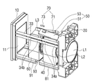
도 1은 본 발명의 일 실시예에 따른 카메라 모듈을 나타낸 사시도이다.
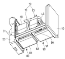
도 2 및 도 3은 도 1에서 케이스를 제거한 상태의 카메라 모듈을 보여주는 각각 사시도들이다.
도 4는 도 2에서 제1 및 제2 코일을 생략한 상태의 카메라 모듈을 나타낸 저면도이다.
도 5는 도 1에서 케이스를 제거한 상태의 카메라 모듈을 보여주는 측면도이다
도 6은 도 5에 표시된 A-A선을 따라 나타낸 단면도이다.
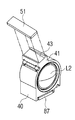
도 7은 제1 가동 렌즈배럴의 상부에 제1 마그네트가 결합된 예를 나타낸 분해사시도이다.
도 8은 도 6에 표시된 B-B선을 따라 나타낸 단면도로서, 마그네트가 C1 및 C2 방향으로 이동 시 홀센서와의 간격을 나타낸 개략도이다.1 is a perspective view showing a camera module according to an embodiment of the present invention.
2 and 3 are perspective views, respectively, showing the camera module in a state in which the case is removed in FIG. 1.
4 is a bottom view of the camera module in a state in which the first and second coils are omitted in FIG. 2.
FIG. 5 is a side view showing the camera module in a state in which the case is removed in FIG. 1.
6 is a cross-sectional view taken along line AA shown in FIG. 5.
7 is an exploded perspective view showing an example in which a first magnet is coupled to an upper portion of the first movable lens barrel.
FIG. 8 is a cross-sectional view taken along the line BB shown in FIG. 6, and is a schematic view showing the distance from the hall sensor when the magnet moves in the C1 and C2 directions.
이하에서는 첨부된 도면을 참조하여 다양한 실시 예를 보다 상세하게 설명한다. 본 명세서에 기재된 실시 예는 다양하게 변형될 수 있다. 특정한 실시 예가 도면에서 묘사되고 상세한 설명에서 자세하게 설명될 수 있다. 그러나, 첨부된 도면에 개시된 특정한 실시 예는 다양한 실시 예를 쉽게 이해하도록 하기 위한 것일 뿐이다. 따라서, 첨부된 도면에 개시된 특정 실시 예에 의해 기술적 사상이 제한되는 것은 아니며, 발명의 사상 및 기술 범위에 포함되는 모든 균등물 또는 대체물을 포함하는 것으로 이해되어야 한다.Hereinafter, various embodiments will be described in detail with reference to the accompanying drawings. The embodiments described herein can be variously modified. Certain embodiments are depicted in the drawings and may be described in detail in the detailed description. However, the specific embodiments disclosed in the accompanying drawings are only for easy understanding of various embodiments. Therefore, it is to be understood that the technical spirit is not limited by the specific embodiments disclosed in the accompanying drawings, and includes all equivalents or substitutes included in the spirit and technical scope of the invention.
제1, 제2 등과 같이 서수를 포함하는 용어는 다양한 구성요소들을 설명하는데 사용될 수 있지만, 이러한 구성요소들은 상술한 용어에 의해 한정되지는 않는다. 상술한 용어는 하나의 구성요소를 다른 구성요소로부터 구별하는 목적으로만 사용된다.Terms including ordinal numbers such as first and second may be used to describe various components, but these components are not limited by the above-described terms. The above-mentioned terms are used only for the purpose of distinguishing one component from other components.
본 명세서에서, "포함한다" 또는 "가지다" 등의 용어는 명세서상에 기재된 특징, 숫자, 단계, 동작, 구성요소, 부품 또는 이들을 조합한 것이 존재함을 지정하려는 것이지, 하나 또는 그 이상의 다른 특징들이나 숫자, 단계, 동작, 구성요소, 부품 또는 이들을 조합한 것들의 존재 또는 부가 가능성을 미리 배제하지 않는 것으로 이해되어야 한다. 어떤 구성요소가 다른 구성요소에 "연결되어" 있다거나 "접속되어" 있다고 언급된 때에는, 그 다른 구성요소에 직접적으로 연결되어 있거나 또는 접속되어 있을 수도 있지만, 중간에 다른 구성요소가 존재할 수도 있다고 이해되어야 할 것이다. 반면에, 어떤 구성요소가 다른 구성요소에 "직접 연결되어" 있다거나 "직접 접속되어" 있다고 언급된 때에는, 중간에 다른 구성요소가 존재하지 않는 것으로 이해되어야 할 것이다.In this specification, the terms "comprises" or "have" are intended to indicate the presence of features, numbers, steps, actions, components, parts or combinations thereof described in the specification, one or more other features. It should be understood that the existence or addition possibilities of fields or numbers, steps, operations, components, parts or combinations thereof are not excluded in advance. When an element is said to be "connected" or "connected" to another component, it is understood that other components may be directly connected to or connected to the other component, but there may be other components in between. It should be. On the other hand, when a component is said to be "directly connected" or "directly connected" to another component, it should be understood that no other component exists in the middle.
그 밖에도, 본 발명을 설명함에 있어서, 관련된 공지 기능 혹은 구성에 대한 구체적인 설명이 본 발명의 요지를 불필요하게 흐릴 수 있다고 판단되는 경우, 그에 대한 상세한 설명은 축약하거나 생략한다.In addition, in describing the present invention, when it is determined that detailed descriptions of related known functions or configurations may unnecessarily obscure the subject matter of the present invention, detailed descriptions thereof are abbreviated or omitted.
본 발명의 일 실시예에 따른 카메라 모듈은 스마트폰과 같은 소형 디지털 기기에 설치될 수 있으며 콤팩트한 크기로 이루어질 수 있다.The camera module according to an embodiment of the present invention may be installed in a small digital device such as a smart phone, and may be formed in a compact size.
도 1 내지 도 8을 참조하여 본 발명의 일 실시예에 따른 카메라 모듈의 구성을 설명한다.A configuration of a camera module according to an embodiment of the present invention will be described with reference to FIGS. 1 to 8.
본 발명의 일 실시예에 따른 카메라 모듈(1)은 베이스(10)와, 베이스(10)에 소정 간격을 두고 배치되는 고정 렌즈배럴(20)과, 베이스(10)와 고정 렌즈배럴(20) 사이에서 광축 방향을 따라 직선왕복 가능하게 배치된 제1 및 제2 가동 렌즈배럴(40,60)과, 제1 가동 렌즈배럴(40)의 위치를 감지하기 위한 제1 위치감지부(50)와, 제2 가동 렌즈배럴(60)의 위치를 감지하기 위한 제2 위치감지부(70)와, 제1 가동 렌즈배럴(40)을 구동시키기 위한 제1 구동부(80)와, 제2 가동 렌즈배럴(60)을 구동시키기 위한 제2 구동부(90)를 포함할 수 있다.The
베이스(10)에는 이미지 센서(미도시)와 적외선 차단 필터(11)가 배치될 수 있다. 적외선 차단 필터(11)는 이미지 센서의 전방에 배치되어 제1 내지 제3 렌즈(L1,L2,L3)를 통해 입사된 광으로부터 적외선을 필터링한다.An image sensor (not shown) and an
고정 렌즈배럴(20)은 제1 및 제2 가동 렌즈배럴(40,60)이 베이스(10)와 고정 렌즈배럴(20) 사이에서 일정 거리만큼 직선 이동할 수 있도록 베이스(10)로부터 소정 간격을 두고 배치된다.The
고정 렌즈배럴(20)은 직선 형태로 이루어진 다수의 제1 및 제2 가이드핀(31,33)에 의해 베이스(10)로부터 일정한 간격을 두면서 베이스(10)와 연결될 수 있다. The
고정 렌즈배럴(20)에는 제1 렌즈(L1)가 결합된다. 제1 렌즈(L1)는 제1 가동 렌즈배럴(40)의 제2 렌즈(L2)와 제2 가동 렌즈배럴(60)의 제3 렌즈(L3)와 함께 광축 상에 배치될 수 있다.The first lens L1 is coupled to the
한 쌍의 제1 가이드핀(31)과 한 쌍의 제2 가이드핀(33)은 서로 평행하게 배치되며 양단이 각각 베이스(10)의 일면(제2 가동 렌즈배럴(60)에 대향하는 면)과 고정 렌즈배럴(20)의 일면(제1 가동 렌즈배럴(40)에 대향하는 면)에 각각 고정될 수 있다.The pair of
또한, 한 쌍의 제1 가이드핀(31)은 제1 및 제2 가동 렌즈배럴(40,60)의 일측 하단에 인접하게 배치되고, 한 쌍의 제2 가이드핀(33)은 제1 및 제2 가동 렌즈배럴(40,60)의 타측 상단에 인접하게 배치된다.In addition, the pair of
제1 가동 렌즈배럴(40)과 한 쌍의 제1 가이드핀(31) 사이에는 다수의 제1 베어링(32a)이 배치될 수 있다. 제1 가동 렌즈배럴(40)은 다수의 제1 베어링(32a)에 의해 한 쌍의 제1 가이드핀(31)에 슬라이딩 가능하게 이동할 수 있다.A plurality of
도 6을 참조하면, 다수의 제1 베어링(32a)은 본 실시예에서 한 쌍이 구비된 것으로 설명한다. 각 제1 베어링(32a)은 볼 타입으로 형성되고 양측으로 축돌기(32c)가 돌출되며 제1 가동 렌즈배럴(40)의 일측 하부에 형성된 V자형 요홈(40a)에 회전 가능하게 삽입된다. 한 쌍의 축돌기(32c)는 V자형 요홈(40a)의 양측으로 연장된 한 쌍의 삽입홈(40b)에 각각 회전 가능하게 삽입된다.또한, 제1 가동 렌즈배럴(40)과 제2 가이드핀(33) 사이에는 다수의 제2 베어링(34a)이 배치될 수 있다. 제1 가동 렌즈배럴(40)은 다수의 제2 베어링(34a)에 의해 한 쌍의 제2 가이드핀(33)에 슬라이딩 가능하게 직선 왕복할 수 있다.Referring to FIG. 6, it is described that a plurality of
도 6을 참조하면, 다수의 제2 베어링(34a)은 본 실시예에서 한 쌍이 구비된 것으로 설명한다. 각 제2 베어링(34a)은 볼 타입으로 형성되고 양측으로 축돌기(34c)가 돌출되며 제1 가동 렌즈배럴(40)의 타측 상부에 형성된 V자형 요홈(40c)에 회전 가능하게 삽입된다. 한 쌍의 축돌기(34c)는 V자형 요홈(40c)의 양측으로 연장된 한 쌍의 삽입홈(40d)에 각가 회전 가능하게 삽입된다.Referring to FIG. 6, it is described that a plurality of
이에 따라, 제1 가동 렌즈배럴(40)은 다수의 제1 및 제2 베어링(32a,34a)에 의해 한 쌍의 제1 및 제2 가이드핀(31,33)을 따라 광축 방향으로 슬라이딩 가능하게 이동할 수 있다.Accordingly, the first
제2 가동 렌즈배럴(60)과 제1 가이드핀(31) 사이에는 다수의 제3 베어링(32b)이 배치될 수 있다. 제2 가동 렌즈배럴(60)은 다수의 제3 베어링(32b)에 의해 한 쌍의 제1 가이드핀(31)에 슬라이딩 가능하게 이동할 수 있다. A plurality of
또한, 제2 가동 렌즈배럴(60)과 제2 가이드핀(33) 사이에는 다수의 제4 베어링(34b)이 배치될 수 있다. 제2 가동 렌즈배럴(60)은 다수의 제4 베어링(34b)에 의해 한 쌍의 제2 가이드핀(33)에 슬라이딩 가능하게 직선 왕복할 수 있다.In addition, a plurality of
도면에 도시하지는 않았으나, 제2 가동 렌즈배럴(60)의 일측 하부 및 타측 상부에는 각각 다수의 제1 및 제2 베어링(32a,34a)이 슬라이딩 가능하게 삽입된 V자형 요홈이 형성되며, 요홈의 양측에는 각 베어링(32a,34a)의 축돌기(32c,34c)가 회전 가능하게 삽입되는 삽입홈이 각각 연장 형성된다.Although not shown in the drawing, a V-shaped groove in which a plurality of first and
이에 따라, 제2 가동 렌즈배럴(60)은 전술한 제1 가동 렌즈배럴(40)과 마찬가지로 다수의 제1 및 제2 베어링(32a,34a)에 의해 한 쌍의 제1 및 제2 가이드핀(31,33)을 따라 광축 방향으로 슬라이딩 가능하게 이동할 수 있다.Accordingly, the second
제1 가동 렌즈배럴(40)은 고정 렌즈배럴(20)과 제2 가동 렌즈배럴(60) 사이에 배치된다. 제2 렌즈(L2)는 제1 가동 렌즈배럴(40)에 결합됨에 따라 제1 가동 렌즈배럴(40)과 함께 직선 왕복 이동할 수 있다. 이에 따라 제2 렌즈(L2)와 제1 렌즈(L1)와의 간격 및 제2 렌즈(L2)와 제3 렌즈(L3)와의 간격이 변경될 수 있다.The first
제2 가동 렌즈배럴(60)은 베이스(10)와 제1 가동 렌즈배럴(40) 사이에 배치된다. 제3 렌즈(L3)는 제2 가동 렌즈배럴(60)에 결합됨에 따라 제2 가동 렌즈배럴(60)과 함께 직선 왕복 이동할 수 있다. 이에 따라 제3 렌즈(L3)와 베이스(10)의 이미지센서와의 간격 및 제3 렌즈(L3)와 제2 렌즈(L2)와의 간격이 변경될 수 있다.The second
이 경우, 제1 및 제2 가동 렌즈배럴(40,60)은 광축을 따라 동시에 이동하거나 어느 하나만 이동할 수 있다. 본 발명의 일 실시예에 따른 카메라 모듈(1)은 상기와 같이 제1 및 제2 가동 렌즈배럴(40,60)이 개별적으로 광축을 따라 직선 왕복 이동하는 구조를 채택함에 따라 광학 줌 기능과 자동초점 조절기능을 개별적으로 수행할 수 있다.In this case, the first and second movable lens barrels 40 and 60 may move simultaneously or only one of them along the optical axis. The
제1 가동 렌즈배럴(40)은 정지 상태나 이동하는 중에 제1 위치감지부(50)에 의해 실시간으로 위치가 감지된다. 이에 따라 카메라 모듈(1)에 구비된 제어부(미도시)는 제1 가동 렌즈배럴(40)의 위치를 실시간으로 파악하여 제1 가동 렌즈배럴(40)을 구동하기 위한 제1 구동부(80)의 구동을 제어함으로써 제1 가동 렌즈배럴(40)의 위치를 정확하게 제어할 수 있다.The first
제1 위치감지부(50)는 제1 가동 렌즈배럴(40)에 결합된 제1 마그네트(51)와, 제1 마그네트(51)의 이동을 감지하는 제1 홀센서(53)를 포함할 수 있다. The first
제1 마그네트(51)는 제1 가동 렌즈배럴(40)의 일측(41)에 형성된 결합홈(43)에 장착된다.The
결합홈(43)은 도 6과 같이 제2 렌즈(L2)의 중심을 지나는 가상의 수직선(110)을 기준으로 일측으로 경사지도록 배치될 수 있다. 이 경우, 제1 마그네트(51)와 제1 홀센서(53)는 가상의 수직선(110)으로부터 일측으로 제1 각도(α1, 제1 각도는 예각일 수 있다)만큼 회전한 위치에 제2 렌즈(L2)의 중심을 지나는 가상의 제1 직선(120) 상에 위치할 수 있다. 바람직하게 제1 마그네트(51)의 중심과 제1 홀센서(53)의 중심은 가상의 제1 직선(120) 상에 위치할 수 있다.The
도 5를 참조하면, 제1 마그네트(51)는 후단부가 제1 가동 렌즈배럴(40)의 후단으로부터 제2 가동 렌즈배럴(60)을 향해 소정 길이 돌출된다. 또한, 후술하는 제2 마그네트(71) 역시 제2 가동 렌즈배럴(60)의 선단으로부터 제1 가동 렌즈배럴(40)을 향해 소정 길이 돌출된다.Referring to FIG. 5, the
이와 같이 제1 및 제2 마그네트(51,71)가 서로 돌출된 상태에서 제1 및 제2 가동 렌즈배럴(40,60)이 상호 직선 방향으로 이동 가능 하려면, 제2 마그네트(71)를 가상의 수직선(110)을 기준으로 타측으로 경사지도록 배치하여 제1 및 제2 마그네트(51,71)가 상호 간섭하지 않도록 하는 것이 바람직하다.As described above, when the first and second movable lens barrels 40 and 60 are movable in a linear direction with each other while the first and
제1 홀센서(53)는 제1 마그네트(51)와 인접하게 배치되도록 케이스(30) 내측 일 부분(미도시)에 고정될 수 있다. The
도 8을 참조하면, 결합홈(43)에 결합된 제1 마그네트(51)는 후단이 선단보다 높게 위치하여 제2 각도(α2)만큼 경사지게 배치될 수 있다. 이와 같이 제1 마그네트(51)가 이동하는 방향을 따라 제2 각도(α2)로 경사지게 배치됨에 따라 제1 마그네트(51)가 이동 시 제1 홀센서(53)와의 간격이 점차 상이하게 변한다.Referring to FIG. 8, the
즉, 제1 가동 렌즈배럴(40)이 일방향 및 그 역방향으로 이동하는 경우, 제1 마그네트(51)와 제1 홀센서(53) 간의 간격은, 제1 간격(d1) 및 제1 간격(d1)과 상이한 제2 간격(d2)이 될 수 있다.That is, when the first
이에 따라, 제1 마그네트(51)가 제1 가동 렌즈배럴(40)과 함께 일 방향 및 그 역방향으로 짧은 거리를 이동하더라도 제1 홀센서(53)에 의해 자기장의 세기 변화가 감지될 수 있으므로, 카메라 모듈의 크기(예를 들면, 길이)를 늘리지 않더라도 제1 마그네트(51)의 제어가 가능하다.Accordingly, even if the
제2 가동 렌즈배럴(60)은 정지 상태나 이동하는 중에 제2 위치감지부(70)에 의해 실시간으로 위치가 감지된다. 이에 따라 제어부는 제2 가동 렌즈배럴(60)의 위치를 실시간으로 파악하여 제2 가동 렌즈배럴(60)을 구동하기 위한 제2 구동부(90)의 구동을 제어함으로써 제2 가동 렌즈배럴(60)의 위치를 정확하게 제어할 수 있다.The position of the second
제2 위치감지부(70)는 제2 가동 렌즈배럴(60)의 일측(61)에 형성된 결합홈(63)에 장착된 제2 마그네트(71)와, 제2 마그네트(71)의 이동을 감지하는 제2 홀센서(73)를 포함할 수 있다. The second
결함홈(63)은 도 6과 같이 가상의 수직선(110)을 기준으로 타측으로 경사지도록 배치될 수 있다. 이 경우, 제2 마그네트(71)와 제2 홀센서(73)는 가상의 수직선(110)으로부터 타측으로 제3 각도(α3, 제3 각도는 예각일 수 있다)만큼 회전한 위치에 제3 렌즈(L3)의 중심을 지나는 가상의 제2 직선(130) 상에 위치할 수 있다. 바람직하게 제2 마그네트(71)의 중심과 제2 홀센서(73)의 중심은 가상의 제2 직선(130) 상에 위치할 수 있다.The
제2 홀센서(73)는 제2 마그네트(71)와 인접하게 배치되도록 케이스(30) 내측 다른 부분(미도시)에 고정될 수 있다. The
도 5를 참조하면, 결합홈(63)에 결합된 제2 마그네트(71)는 선단이 후단보다 높게 위치하여 제4 각도(α4)만큼 경사지게 배치될 수 있다. 이와 같이 제2 마그네트(71)를 이동하는 방향을 따라 제4 각도(α4)로 경사지게 배치함에 따라 제2 마그네트(71)가 이동 시 제2 홀센서(73)와의 간격이 점차 상이하게 변한다.Referring to FIG. 5, the
즉, 제2 가동 렌즈배럴(60)이 일방향 및 그 역방향으로 이동하는 경우, 제2 마그네트(71)와 제2 홀센서(73) 간의 간격은, 제3 간격 및 제3 간격과 상이한 제4 간격이 될 수 있다.That is, when the second
이와 같이 제2 마그네트(71)를 제4 각도(α4)로 경사지게 배치하게 되면, 제2 마그네트(71)가 제2 가동 렌즈배럴(60)과 함께 일 방향 및 그 역방향으로 짧은 거리를 이동하더라도 제2 홀센서(73)에 의해 자기장의 세기 변화가 감지될 수 있으므로, 카메라 모듈의 크기(예를 들면, 길이)를 늘리지 않더라도 제2 마그네트(71)의 제어가 가능하다.When the
제1 구동부(80)는 제1 위치감지부(50)의 위치에 대하여 대략 반대편에 배치될 수 있다. 제1 구동부(80)는 제1 가동 렌즈배럴(40)의 타측에 소정 간격을 두고 배치된 제1 코일(81)과, 제1 코일(81)에 전류를 인가 시 제1 코일(81)에 형성되는 자기장에 반응하는 제1 구동 마그네트(85)를 포함할 수 있다. The
제1 코일(81)은 제1 요크(83)에 권선된 상태로 케이스(30) 내측에 고정된다.The
제1 구동 마그네트(85)는 제1 코일(81)에 마주하도록 제1 가동 렌즈배럴(40)의 타측에 결합됨에 따라, 제1 가동 렌즈배럴(40)과 함께 직선 이동한다. 제1 구동 마그네트(85)는 제1 코일(81)을 향하는 면을 제외한 나머지 면이 제1 차폐부재(87)에 의해 둘러싸인다. The
제2 구동부(90)는 제2 위치감지부(70)의 위치에 대하여 대략 반대편에 배치될 수 있다. 제2 구동부(90)는 제2 가동 렌즈배럴(60)의 타측에 소정 간격을 두고 배치된 제2 코일(91)과, 제2 코일(91)에 전류를 인가 시 제2 코일(91)에 형성되는 자기장에 반응하는 제2 구동 마그네트(95)를 포함할 수 있다. The
제2 코일(91)은 제2 요크(93)에 권선된 상태로 케이스(30) 내측에 고정된다.The
제2 구동 마그네트(95)는 제2 코일(91)에 마주하도록 제2 가동 렌즈배럴(60)의 타측에 결합됨에 따라, 제2 가동 렌즈배럴(60)과 함께 직선 이동한다. 제2 구동 마그네트(95)는 제2 코일(91)을 향하는 면을 제외한 나머지 면이 제2 차폐부재(97)에 의해 둘러싸인다. The
상기와 같이 구성된 본 발명은 하기와 같은 방법으로 줌 기능 및 가변초점조절 기능을 구현할 수 있다.The present invention configured as described above can implement a zoom function and a variable focus adjustment function in the following manner.
즉, 제어부는 제1 구동부(80)에 의해 제1 가동 렌즈배럴(40)을 일 방향 및 그 역방향으로 이동 시 제1 위치감지부(50)를 통해 실시간으로 가변되는 제1 가동 렌즈배럴(40)의 위치에 대한 감지신호를 수신하고, 이 감지신호를 기반으로 제1 구동부(80)를 제어함으로써 제1 가동 렌즈배럴(40)을 원하는 위치로 정확하게 이동시킬 수 있다.That is, when the first
마찬가지로, 제어부는 제2 구동부(90)에 의해 제2 가동 렌즈배럴(60)을 일 방향 및 그 역방향으로 이동 시 제2 위치감지부(70)를 통해 실시간으로 가변되는 제2 가동 렌즈배럴(60)의 위치에 대한 감지신호를 수신하고, 이 감지신호를 기반으로 제2 구동부(90)를 제어함으로써 제2 가동 렌즈배럴(60)을 원하는 위치로 정확하게 이동시킬 수 있다.Likewise, when the second
1: 카메라 모듈
10: 베이스
11: 적외선 차단 필터
20: 고정 렌즈배럴
31,33: 가이드핀
32a,32b,34a,34b: 베어링
40: 제1 가동 렌즈배럴
50: 제1 위치감지부
60: 제2 가동 렌즈배럴
70: 제2 위치감지부
80: 제1 구동부
90: 제2 구동부
L1: 제1 렌즈
L2: 제2 렌즈
L3: 제3 렌즈1: Camera module 10: Base
11: Infrared cut filter 20: Fixed lens barrel
31,33: guide
40: first movable lens barrel 50: first position detection unit
60: second movable lens barrel 70: second position detection unit
80: first drive unit 90: second drive unit
L1: First lens L2: Second lens
L3: third lens
Claims (10)
상기 케이스 일단에 배치되고 이미지 센서가 장착되는 베이스;
상기 케이스 타단에 배치되고 제1 렌즈를 구비한 고정 렌즈배럴;
양단이 각각 상기 베이스와 상기 고정 렌즈배럴에 연결되고 평행하게 배치된 다수의 가이드 핀;
상기 베이스와 상기 고정 렌즈배럴 사이에서 상기 다수의 가이드 핀을 따라 이동 가능하게 배치되고, 각각 제2 및 제3 렌즈를 구비한 제1 및 제2 가동 렌즈배럴;
상기 제1 및 제2 가동 렌즈배럴을 각각 구동하기 위한 제1 및 제2 구동부; 및
상기 제1 및 제2 가동 렌즈배럴의 위치를 각각 감지하기 위한 제1 및 제2 위치감지부;를 포함하며,
상기 제1 위치감지부는, 상기 케이스에 고정된 제1 홀센서와, 상기 제1 가동 렌즈배럴의 이동에 따라 상기 제1 홀센서와의 간격이 가변되도록 상기 상기 제1 가동 렌즈배럴에 결합된 제1 마그네트를 포함하고,
상기 제2 위치감지부는, 상기 케이스에 고정된 제2 홀센서와, 상기 제2 가동 렌즈배럴의 이동에 따라 상기 제2 홀센서와의 간격이 가변되도록 상기 제2 가동 렌즈배럴에 결합된 제2 마그네트를 포함한 것을 특징으로 하는 카메라 모듈.case;
A base disposed on one end of the case and mounted with an image sensor;
A fixed lens barrel disposed at the other end of the case and having a first lens;
A plurality of guide pins, both ends of which are connected to the base and the fixed lens barrel and arranged in parallel;
First and second movable lens barrels disposed movably along the plurality of guide pins between the base and the fixed lens barrel, each having second and third lenses;
First and second driving units for driving the first and second movable lens barrels, respectively; And
It includes; first and second position detection unit for sensing the position of the first and second movable lens barrel, respectively;
The first position sensing unit, the first Hall sensor fixed to the case, the first movable lens barrel coupled to the first movable lens barrel so that the distance between the first Hall sensor according to the movement of the variable 1 magnet,
The second position sensing unit, the second hole sensor fixed to the case, the second movable lens barrel coupled to the second movable lens barrel so that the distance between the second Hall sensor is variable according to the movement of the A camera module comprising a magnet.
상기 제1 마그네트는 상기 제1 마그네트가 이동하는 방향을 따라 경사지게 배치되며,
상기 제2 마그네트는 상기 제2 마그네트가 이동하는 방향을 따라 경사지게 배치된 것을 특징으로 하는 카메라 모듈.According to claim 1,
The first magnet is inclined along the direction in which the first magnet moves,
The second magnet is a camera module, characterized in that disposed in an inclined direction along the direction in which the second magnet moves.
상기 제1 마그네트는 상기 고정 렌즈배럴 측으로 기울어지게 배치되고,
상기 제2 마그네트는 상기 베이스 측으로 기울어지게 배치된 것을 특징으로 하는 카메라 모듈.According to claim 2,
The first magnet is disposed to be inclined toward the fixed lens barrel,
The second magnet is a camera module, characterized in that disposed inclined toward the base.
상기 제1 마그네트는 일단이 상기 제2 가동 렌즈배럴 측으로 돌출되며,
상기 제2 마그네트는 일단이 상기 제1 가동 렌즈배럴 측으로 돌출된 것을 특징으로 하는 카메라 모듈.According to claim 3,
One end of the first magnet protrudes toward the second movable lens barrel,
The second magnet is a camera module, characterized in that one end protrudes toward the first movable lens barrel.
상기 제1 마그네트와 상기 제2 마그네트는 서로 비간섭하도록 광축에 수직한 가상의 수직선에 대해 서로 반대 방향으로 일정 각도만큼 회전된 위치에 배치된 것을 특징으로 하는 카메라 모듈.According to claim 2,
The first magnet and the second magnet is a camera module, characterized in that arranged at a position rotated by a predetermined angle in the opposite direction to each other with respect to the virtual vertical line perpendicular to the optical axis so as not to interfere with each other.
상기 제1 및 제2 구동부는 각각 상기 제1 및 제2 위치감지부의 반대편에 배치된 것을 특징으로 하는 카메라 모듈.The method of claim 5,
The first and second driving units are respectively disposed on opposite sides of the first and second position sensing units, a camera module.
상기 다수의 가이드핀은,
상기 제1 및 제2 가동 렌즈배럴의 일측 상단을 슬라이딩 가능하게 지지하는 한 쌍의 제1 가이드핀; 및
상기 제1 및 제2 가동 렌즈배럴의 타측 하단을 슬라이딩 가능하게 지지하는 한 쌍의 제2 가이드핀;을 포함한 것을 특징으로 하는 카메라 모듈.The method of claim 6,
The plurality of guide pins,
A pair of first guide pins slidably supporting one upper end of the first and second movable lens barrels; And
And a pair of second guide pins slidably supporting the lower ends of the other side of the first and second movable lens barrels.
상기 제1 및 제2 가동 렌즈배럴과 상기 한 쌍의 제1 가이드핀 사이 및 상기 제1 및 제2 가동 렌즈배럴과 상기 한 쌍의 제2 가이드핀 사이에는 각각 다수의 베어링;이 배치된 것을 특징으로 하는 카메라 모듈.The method of claim 7,
It characterized in that a plurality of bearings are disposed between the first and second movable lens barrels and the pair of first guide pins and between the first and second movable lens barrels and the pair of second guide pins, respectively. Camera module.
상기 다수의 베어링은,
상기 제1 가동 렌즈배럴의 일측 상단부에 회전 가능하게 배치된 한 쌍의 제1 베어링;
상기 제1 가동 렌즈배럴의 타측 하단부에 회전 가능하게 배치된 한 쌍의 제2 베어링;
상기 제2 가동 렌즈배럴의 일측 상단부에 회전 가능하게 배치된 한 쌍의 제3 베어링; 및
상기 제2 가동 렌즈배럴의 타측 하단부에 회전 가능하게 배치된 한 쌍의 제4 베어링;을 포함한 것을 특징으로 하는 카메라 모듈.The method of claim 8,
The plurality of bearings,
A pair of first bearings rotatably disposed at an upper end of one side of the first movable lens barrel;
A pair of second bearings rotatably arranged at the lower end of the other side of the first movable lens barrel;
A pair of third bearings rotatably arranged at an upper end of one side of the second movable lens barrel; And
And a pair of fourth bearings rotatably disposed at the lower end of the other side of the second movable lens barrel.
상기 한 쌍의 제1 및 제2 베어링은 각각 상기 제1 가동 렌즈배럴에 형성된 V자형 요홈에 삽입되고, 양측으로 회전 중심이 되는 한 쌍의 축돌기가 구비되며,
상기 한 쌍의 제3 및 제4 베어링은 각각 상기 제2 가동 렌즈배럴에 형성된 V자형 요홈에 삽입되고, 양측으로 회전 중심이 되는 한 쌍의 축돌기가 구비된 것을 특징으로 하는 카메라 모듈.The method of claim 9,
The pair of first and second bearings are respectively inserted into V-shaped grooves formed in the first movable lens barrel, and provided with a pair of shaft protrusions which are rotation centers on both sides,
The pair of third and fourth bearings are respectively inserted into a V-shaped groove formed in the second movable lens barrel, and a camera module, characterized in that a pair of shaft protrusions provided as rotation centers on both sides is provided.
Applications Claiming Priority (2)
| Application Number | Priority Date | Filing Date | Title |
|---|---|---|---|
| KR20180144833 | 2018-11-21 | ||
| KR1020180144833 | 2018-11-21 |
Publications (1)
| Publication Number | Publication Date |
|---|---|
| KR20200060201A true KR20200060201A (en) | 2020-05-29 |
Family
ID=70911409
Family Applications (1)
| Application Number | Title | Priority Date | Filing Date |
|---|---|---|---|
| KR1020190038839A KR20200060201A (en) | 2018-11-21 | 2019-04-03 | Camera module |
Country Status (1)
| Country | Link |
|---|---|
| KR (1) | KR20200060201A (en) |
Cited By (1)
| Publication number | Priority date | Publication date | Assignee | Title |
|---|---|---|---|---|
| WO2022102934A1 (en) * | 2020-11-12 | 2022-05-19 | 자화전자 주식회사 | Zoom drive actuator |
-
2019
- 2019-04-03 KR KR1020190038839A patent/KR20200060201A/en not_active Application Discontinuation
Cited By (1)
| Publication number | Priority date | Publication date | Assignee | Title |
|---|---|---|---|---|
| WO2022102934A1 (en) * | 2020-11-12 | 2022-05-19 | 자화전자 주식회사 | Zoom drive actuator |
Similar Documents
| Publication | Publication Date | Title |
|---|---|---|
| KR102400386B1 (en) | Apparatus for driving zoom lens | |
| US10564442B2 (en) | Apparatus for driving optical-reflector for OIS with multi-axial structure | |
| KR102140582B1 (en) | Apparatus for driving optical-reflector with multi-axial structure | |
| KR101947763B1 (en) | Camera lens assembly | |
| CN111758070B (en) | Camera module | |
| KR101771439B1 (en) | Auto Focusing Apparatus | |
| CN111684353B (en) | Camera module | |
| CN107918183A (en) | Equipment for driving optical reflector | |
| KR20180135392A (en) | Lens driving apparatus and camera lens module including the same | |
| EP3584624B1 (en) | Reflection system driving device having multi-axis structure | |
| KR102566880B1 (en) | Auto focusing apparatus | |
| KR20170051928A (en) | Camera module | |
| EP3525027A2 (en) | Reflectometer driving device for ois | |
| CN111630451B (en) | Lens assembly and camera module with same | |
| KR20190036372A (en) | Camera module | |
| KR102090827B1 (en) | Camera module and flat-type coil for long stroke | |
| US8411381B2 (en) | Lens barrel | |
| KR20200060201A (en) | Camera module | |
| KR101874431B1 (en) | Auto focusing apparatus for three dimensional camera module | |
| KR101511065B1 (en) | Auto focus actuator and camera lens assembly containing the same | |
| KR20200035522A (en) | Apparatus for operating lens | |
| US20240080560A1 (en) | Camera actuator and camera module including same | |
| KR20190121951A (en) | Camera module for improvement of linearity | |
| KR102610809B1 (en) | Lens assembly | |
| KR102443135B1 (en) | LiDAR |
Legal Events
| Date | Code | Title | Description |
|---|---|---|---|
| E902 | Notification of reason for refusal |