KR20200057057A - Wing tilt drive system for electric vertical take-off and landing (VTOL) aircraft - Google Patents
Wing tilt drive system for electric vertical take-off and landing (VTOL) aircraft Download PDFInfo
- Publication number
- KR20200057057A KR20200057057A KR1020207011614A KR20207011614A KR20200057057A KR 20200057057 A KR20200057057 A KR 20200057057A KR 1020207011614 A KR1020207011614 A KR 1020207011614A KR 20207011614 A KR20207011614 A KR 20207011614A KR 20200057057 A KR20200057057 A KR 20200057057A
- Authority
- KR
- South Korea
- Prior art keywords
- aircraft
- motor
- vtol
- landing
- control surface
- Prior art date
Links
- 230000004044 response Effects 0.000 claims description 6
- 230000008859 change Effects 0.000 claims description 5
- 230000001133 acceleration Effects 0.000 claims description 3
- 230000007246 mechanism Effects 0.000 description 5
- 241000234435 Lilium Species 0.000 description 3
- 230000006641 stabilisation Effects 0.000 description 3
- 238000011105 stabilization Methods 0.000 description 3
- 230000007423 decrease Effects 0.000 description 2
- 230000003068 static effect Effects 0.000 description 2
- 230000007704 transition Effects 0.000 description 2
- 230000000712 assembly Effects 0.000 description 1
- 238000000429 assembly Methods 0.000 description 1
- 239000000969 carrier Substances 0.000 description 1
- 230000000295 complement effect Effects 0.000 description 1
- 230000008878 coupling Effects 0.000 description 1
- 238000010168 coupling process Methods 0.000 description 1
- 238000005859 coupling reaction Methods 0.000 description 1
- 230000003247 decreasing effect Effects 0.000 description 1
- 238000010586 diagram Methods 0.000 description 1
- 238000005516 engineering process Methods 0.000 description 1
- 230000005484 gravity Effects 0.000 description 1
- 230000006872 improvement Effects 0.000 description 1
- 238000004519 manufacturing process Methods 0.000 description 1
- 238000002156 mixing Methods 0.000 description 1
Images


Classifications
-
- B—PERFORMING OPERATIONS; TRANSPORTING
- B64—AIRCRAFT; AVIATION; COSMONAUTICS
- B64C—AEROPLANES; HELICOPTERS
- B64C27/00—Rotorcraft; Rotors peculiar thereto
- B64C27/22—Compound rotorcraft, i.e. aircraft using in flight the features of both aeroplane and rotorcraft
- B64C27/28—Compound rotorcraft, i.e. aircraft using in flight the features of both aeroplane and rotorcraft with forward-propulsion propellers pivotable to act as lifting rotors
-
- B—PERFORMING OPERATIONS; TRANSPORTING
- B64—AIRCRAFT; AVIATION; COSMONAUTICS
- B64C—AEROPLANES; HELICOPTERS
- B64C9/00—Adjustable control surfaces or members, e.g. rudders
- B64C9/14—Adjustable control surfaces or members, e.g. rudders forming slots
- B64C9/16—Adjustable control surfaces or members, e.g. rudders forming slots at the rear of the wing
- B64C9/18—Adjustable control surfaces or members, e.g. rudders forming slots at the rear of the wing by single flaps
-
- B—PERFORMING OPERATIONS; TRANSPORTING
- B64—AIRCRAFT; AVIATION; COSMONAUTICS
- B64C—AEROPLANES; HELICOPTERS
- B64C29/00—Aircraft capable of landing or taking-off vertically, e.g. vertical take-off and landing [VTOL] aircraft
- B64C29/0008—Aircraft capable of landing or taking-off vertically, e.g. vertical take-off and landing [VTOL] aircraft having its flight directional axis horizontal when grounded
- B64C29/0016—Aircraft capable of landing or taking-off vertically, e.g. vertical take-off and landing [VTOL] aircraft having its flight directional axis horizontal when grounded the lift during taking-off being created by free or ducted propellers or by blowers
- B64C29/0033—Aircraft capable of landing or taking-off vertically, e.g. vertical take-off and landing [VTOL] aircraft having its flight directional axis horizontal when grounded the lift during taking-off being created by free or ducted propellers or by blowers the propellers being tiltable relative to the fuselage
-
- B—PERFORMING OPERATIONS; TRANSPORTING
- B60—VEHICLES IN GENERAL
- B60L—PROPULSION OF ELECTRICALLY-PROPELLED VEHICLES; SUPPLYING ELECTRIC POWER FOR AUXILIARY EQUIPMENT OF ELECTRICALLY-PROPELLED VEHICLES; ELECTRODYNAMIC BRAKE SYSTEMS FOR VEHICLES IN GENERAL; MAGNETIC SUSPENSION OR LEVITATION FOR VEHICLES; MONITORING OPERATING VARIABLES OF ELECTRICALLY-PROPELLED VEHICLES; ELECTRIC SAFETY DEVICES FOR ELECTRICALLY-PROPELLED VEHICLES
- B60L15/00—Methods, circuits, or devices for controlling the traction-motor speed of electrically-propelled vehicles
- B60L15/20—Methods, circuits, or devices for controlling the traction-motor speed of electrically-propelled vehicles for control of the vehicle or its driving motor to achieve a desired performance, e.g. speed, torque, programmed variation of speed
-
- B—PERFORMING OPERATIONS; TRANSPORTING
- B64—AIRCRAFT; AVIATION; COSMONAUTICS
- B64C—AEROPLANES; HELICOPTERS
- B64C1/00—Fuselages; Constructional features common to fuselages, wings, stabilising surfaces or the like
- B64C1/14—Windows; Doors; Hatch covers or access panels; Surrounding frame structures; Canopies; Windscreens accessories therefor, e.g. pressure sensors, water deflectors, hinges, seals, handles, latches, windscreen wipers
- B64C1/1407—Doors; surrounding frames
-
- B—PERFORMING OPERATIONS; TRANSPORTING
- B64—AIRCRAFT; AVIATION; COSMONAUTICS
- B64C—AEROPLANES; HELICOPTERS
- B64C11/00—Propellers, e.g. of ducted type; Features common to propellers and rotors for rotorcraft
- B64C11/30—Blade pitch-changing mechanisms
- B64C11/305—Blade pitch-changing mechanisms characterised by being influenced by other control systems, e.g. fuel supply
-
- B—PERFORMING OPERATIONS; TRANSPORTING
- B64—AIRCRAFT; AVIATION; COSMONAUTICS
- B64C—AEROPLANES; HELICOPTERS
- B64C13/00—Control systems or transmitting systems for actuating flying-control surfaces, lift-increasing flaps, air brakes, or spoilers
-
- B—PERFORMING OPERATIONS; TRANSPORTING
- B64—AIRCRAFT; AVIATION; COSMONAUTICS
- B64C—AEROPLANES; HELICOPTERS
- B64C13/00—Control systems or transmitting systems for actuating flying-control surfaces, lift-increasing flaps, air brakes, or spoilers
- B64C13/02—Initiating means
-
- B—PERFORMING OPERATIONS; TRANSPORTING
- B64—AIRCRAFT; AVIATION; COSMONAUTICS
- B64C—AEROPLANES; HELICOPTERS
- B64C15/00—Attitude, flight direction, or altitude control by jet reaction
-
- B—PERFORMING OPERATIONS; TRANSPORTING
- B64—AIRCRAFT; AVIATION; COSMONAUTICS
- B64C—AEROPLANES; HELICOPTERS
- B64C23/00—Influencing air flow over aircraft surfaces, not otherwise provided for
- B64C23/06—Influencing air flow over aircraft surfaces, not otherwise provided for by generating vortices
- B64C23/065—Influencing air flow over aircraft surfaces, not otherwise provided for by generating vortices at the wing tips
- B64C23/069—Influencing air flow over aircraft surfaces, not otherwise provided for by generating vortices at the wing tips using one or more wing tip airfoil devices, e.g. winglets, splines, wing tip fences or raked wingtips
-
- B—PERFORMING OPERATIONS; TRANSPORTING
- B64—AIRCRAFT; AVIATION; COSMONAUTICS
- B64C—AEROPLANES; HELICOPTERS
- B64C27/00—Rotorcraft; Rotors peculiar thereto
- B64C27/52—Tilting of rotor bodily relative to fuselage
-
- B—PERFORMING OPERATIONS; TRANSPORTING
- B64—AIRCRAFT; AVIATION; COSMONAUTICS
- B64C—AEROPLANES; HELICOPTERS
- B64C27/00—Rotorcraft; Rotors peculiar thereto
- B64C27/54—Mechanisms for controlling blade adjustment or movement relative to rotor head, e.g. lag-lead movement
- B64C27/80—Mechanisms for controlling blade adjustment or movement relative to rotor head, e.g. lag-lead movement for differential adjustment of blade pitch between two or more lifting rotors
-
- B—PERFORMING OPERATIONS; TRANSPORTING
- B64—AIRCRAFT; AVIATION; COSMONAUTICS
- B64C—AEROPLANES; HELICOPTERS
- B64C27/00—Rotorcraft; Rotors peculiar thereto
- B64C27/82—Rotorcraft; Rotors peculiar thereto characterised by the provision of an auxiliary rotor or fluid-jet device for counter-balancing lifting rotor torque or changing direction of rotorcraft
-
- B—PERFORMING OPERATIONS; TRANSPORTING
- B64—AIRCRAFT; AVIATION; COSMONAUTICS
- B64C—AEROPLANES; HELICOPTERS
- B64C29/00—Aircraft capable of landing or taking-off vertically, e.g. vertical take-off and landing [VTOL] aircraft
-
- B—PERFORMING OPERATIONS; TRANSPORTING
- B64—AIRCRAFT; AVIATION; COSMONAUTICS
- B64C—AEROPLANES; HELICOPTERS
- B64C3/00—Wings
- B64C3/38—Adjustment of complete wings or parts thereof
-
- B—PERFORMING OPERATIONS; TRANSPORTING
- B64—AIRCRAFT; AVIATION; COSMONAUTICS
- B64C—AEROPLANES; HELICOPTERS
- B64C39/00—Aircraft not otherwise provided for
- B64C39/02—Aircraft not otherwise provided for characterised by special use
- B64C39/024—Aircraft not otherwise provided for characterised by special use of the remote controlled vehicle type, i.e. RPV
-
- B—PERFORMING OPERATIONS; TRANSPORTING
- B64—AIRCRAFT; AVIATION; COSMONAUTICS
- B64C—AEROPLANES; HELICOPTERS
- B64C39/00—Aircraft not otherwise provided for
- B64C39/06—Aircraft not otherwise provided for having disc- or ring-shaped wings
- B64C39/068—Aircraft not otherwise provided for having disc- or ring-shaped wings having multiple wings joined at the tips
-
- B—PERFORMING OPERATIONS; TRANSPORTING
- B64—AIRCRAFT; AVIATION; COSMONAUTICS
- B64C—AEROPLANES; HELICOPTERS
- B64C9/00—Adjustable control surfaces or members, e.g. rudders
-
- B—PERFORMING OPERATIONS; TRANSPORTING
- B64—AIRCRAFT; AVIATION; COSMONAUTICS
- B64C—AEROPLANES; HELICOPTERS
- B64C9/00—Adjustable control surfaces or members, e.g. rudders
- B64C9/14—Adjustable control surfaces or members, e.g. rudders forming slots
- B64C9/16—Adjustable control surfaces or members, e.g. rudders forming slots at the rear of the wing
-
- B—PERFORMING OPERATIONS; TRANSPORTING
- B64—AIRCRAFT; AVIATION; COSMONAUTICS
- B64D—EQUIPMENT FOR FITTING IN OR TO AIRCRAFT; FLIGHT SUITS; PARACHUTES; ARRANGEMENTS OR MOUNTING OF POWER PLANTS OR PROPULSION TRANSMISSIONS IN AIRCRAFT
- B64D27/00—Arrangement or mounting of power plant in aircraft; Aircraft characterised thereby
- B64D27/02—Aircraft characterised by the type or position of power plant
- B64D27/24—Aircraft characterised by the type or position of power plant using steam, electricity, or spring force
-
- B64D27/40—
-
- H—ELECTRICITY
- H02—GENERATION; CONVERSION OR DISTRIBUTION OF ELECTRIC POWER
- H02K—DYNAMO-ELECTRIC MACHINES
- H02K1/00—Details of the magnetic circuit
- H02K1/06—Details of the magnetic circuit characterised by the shape, form or construction
- H02K1/22—Rotating parts of the magnetic circuit
- H02K1/27—Rotor cores with permanent magnets
-
- B—PERFORMING OPERATIONS; TRANSPORTING
- B60—VEHICLES IN GENERAL
- B60L—PROPULSION OF ELECTRICALLY-PROPELLED VEHICLES; SUPPLYING ELECTRIC POWER FOR AUXILIARY EQUIPMENT OF ELECTRICALLY-PROPELLED VEHICLES; ELECTRODYNAMIC BRAKE SYSTEMS FOR VEHICLES IN GENERAL; MAGNETIC SUSPENSION OR LEVITATION FOR VEHICLES; MONITORING OPERATING VARIABLES OF ELECTRICALLY-PROPELLED VEHICLES; ELECTRIC SAFETY DEVICES FOR ELECTRICALLY-PROPELLED VEHICLES
- B60L2200/00—Type of vehicles
- B60L2200/10—Air crafts
-
- B—PERFORMING OPERATIONS; TRANSPORTING
- B64—AIRCRAFT; AVIATION; COSMONAUTICS
- B64C—AEROPLANES; HELICOPTERS
- B64C27/00—Rotorcraft; Rotors peculiar thereto
- B64C27/82—Rotorcraft; Rotors peculiar thereto characterised by the provision of an auxiliary rotor or fluid-jet device for counter-balancing lifting rotor torque or changing direction of rotorcraft
- B64C2027/8227—Rotorcraft; Rotors peculiar thereto characterised by the provision of an auxiliary rotor or fluid-jet device for counter-balancing lifting rotor torque or changing direction of rotorcraft comprising more than one rotor
-
- Y—GENERAL TAGGING OF NEW TECHNOLOGICAL DEVELOPMENTS; GENERAL TAGGING OF CROSS-SECTIONAL TECHNOLOGIES SPANNING OVER SEVERAL SECTIONS OF THE IPC; TECHNICAL SUBJECTS COVERED BY FORMER USPC CROSS-REFERENCE ART COLLECTIONS [XRACs] AND DIGESTS
- Y02—TECHNOLOGIES OR APPLICATIONS FOR MITIGATION OR ADAPTATION AGAINST CLIMATE CHANGE
- Y02T—CLIMATE CHANGE MITIGATION TECHNOLOGIES RELATED TO TRANSPORTATION
- Y02T10/00—Road transport of goods or passengers
- Y02T10/60—Other road transportation technologies with climate change mitigation effect
- Y02T10/72—Electric energy management in electromobility
-
- Y—GENERAL TAGGING OF NEW TECHNOLOGICAL DEVELOPMENTS; GENERAL TAGGING OF CROSS-SECTIONAL TECHNOLOGIES SPANNING OVER SEVERAL SECTIONS OF THE IPC; TECHNICAL SUBJECTS COVERED BY FORMER USPC CROSS-REFERENCE ART COLLECTIONS [XRACs] AND DIGESTS
- Y02—TECHNOLOGIES OR APPLICATIONS FOR MITIGATION OR ADAPTATION AGAINST CLIMATE CHANGE
- Y02T—CLIMATE CHANGE MITIGATION TECHNOLOGIES RELATED TO TRANSPORTATION
- Y02T50/00—Aeronautics or air transport
- Y02T50/10—Drag reduction
-
- Y—GENERAL TAGGING OF NEW TECHNOLOGICAL DEVELOPMENTS; GENERAL TAGGING OF CROSS-SECTIONAL TECHNOLOGIES SPANNING OVER SEVERAL SECTIONS OF THE IPC; TECHNICAL SUBJECTS COVERED BY FORMER USPC CROSS-REFERENCE ART COLLECTIONS [XRACs] AND DIGESTS
- Y02—TECHNOLOGIES OR APPLICATIONS FOR MITIGATION OR ADAPTATION AGAINST CLIMATE CHANGE
- Y02T—CLIMATE CHANGE MITIGATION TECHNOLOGIES RELATED TO TRANSPORTATION
- Y02T50/00—Aeronautics or air transport
- Y02T50/40—Weight reduction
-
- Y—GENERAL TAGGING OF NEW TECHNOLOGICAL DEVELOPMENTS; GENERAL TAGGING OF CROSS-SECTIONAL TECHNOLOGIES SPANNING OVER SEVERAL SECTIONS OF THE IPC; TECHNICAL SUBJECTS COVERED BY FORMER USPC CROSS-REFERENCE ART COLLECTIONS [XRACs] AND DIGESTS
- Y02—TECHNOLOGIES OR APPLICATIONS FOR MITIGATION OR ADAPTATION AGAINST CLIMATE CHANGE
- Y02T—CLIMATE CHANGE MITIGATION TECHNOLOGIES RELATED TO TRANSPORTATION
- Y02T50/00—Aeronautics or air transport
- Y02T50/60—Efficient propulsion technologies, e.g. for aircraft
-
- Y02T50/62—
Abstract
수직 이착륙 (VTOL) 항공기(10)는 동체와 제1 및 제2 전방 날개(20,22)를 포함하되, 각각의 날개(20,22)는 고정된 리딩 엣지 및 대체로 수평한 회동 축을 중심으로 회동하는 후미 제어 표면(50)을 구비한다. 항공기(10)는 각각이 로터(70)를 구비하는 제1 및 제2 전기 모터(60)를 포함하고, 상기 전기 로터(70)는 각각의 로터(70)가 대체로 수직한 회전 축을 가지는 제1 위치 및 각각의 로터(70)가 대체로 수평한 회전 축을 가지는 제2 위치 사이에서 후미 제어 표면(50)과 함께 회동하며, 제어 시스템(90)은 회동 축(33)을 중심으로 제어 표면(50)을 회동시키기 위한 회전 모멘트를 생성하도록, 상이한 회전 속도에서 제1 전기 모터(60) 및 제2 전기 모터(60)를 선택적으로 작동시키도록 구성된다.Vertical takeoff and landing (VTOL) aircraft 10 includes a fuselage and first and second front wings 20 and 22, each wing 20 and 22 pivoting around a fixed leading edge and a generally horizontal pivot axis. The rear end control surface 50 is provided. The aircraft 10 includes first and second electric motors 60 each having a rotor 70, and the electric rotor 70 includes a first in which each rotor 70 has a generally vertical rotation axis. The control system 90 rotates with the trailing control surface 50 between the position and a second position where each rotor 70 has a generally horizontal axis of rotation, and the control system 90 controls the control surface 50 about the rotation axis 33 It is configured to selectively operate the first electric motor (60) and the second electric motor (60) at different rotational speeds, to generate a rotational moment for rotating the motor.
Description
본 개시는 전기 수직 이착륙 (VTOL) 항공기용 윙 틸트 구동 시스템에 관한 것이다. 특히, 본 발명은 여객 및/또는 군사적 용도를 지니는 전기 VTOL 항공기에 대한 윙 틸트 구동 시스템 및 메커니즘에 관한 것이다.The present disclosure relates to a wing tilt drive system for an electric vertical take-off and landing (VTOL) aircraft. In particular, the present invention relates to wing tilt drive systems and mechanisms for electric VTOL aircraft having passenger and / or military uses.
VTOL 항공기는 수직으로 또는 거의 수직에 가까운 소정 각도로 이착륙을 할 수 있다. 이러한 항공기의 종류는 헬리콥터 및 소정의 날개 고정형 항공기를 포함하며, 군사용으로 자주 활용된다. VTOL 항공기는 제한된 공간에서 이착륙이 가능하며, 큰 활주로의 필요성을 없애고, 보트 데크 및 건물과 기타 구조물의 랜딩 패드와 같은 작은 공간에서의 이착륙이 가능하다.VTOL aircraft can take off and land vertically or at almost any angle. These types of aircraft include helicopters and certain fixed-wing aircraft, and are frequently used for military purposes. VTOL aircraft can take off and land in limited spaces, eliminate the need for large runways, and take off and land in small spaces such as boat decks and landing pads for buildings and other structures.
헬리콥터는 양력과 추력 양자가 로터에 의해 제공되는 항공기의 한 종류이다. 헬리콥터와 관련된 몇 가지 이슈가 있는데, 일부 응용에서 높은 수준의 소음 출력과 같은 문제가 있을 수 있다. 헬리콥터와 연관된 이러한 단점에는 비행에 중요한 로터의 설계와 관련이 있다. 일반적으로 설계에는 여유(redundancy)가 없으며, 이는 로터(혹은 각각의 로터)의 동작이 중요함을 의미한다. 이러한 여유의 부족은 안정성의 큰 요인들이 로터 및 구동 트레인의 모든 구성 요소에 적용되어야 함을 나타내고, 그로 인해 헬리콥터의 무게 및 제조 비용이 상당히 증가하게 된다.Helicopters are a type of aircraft in which both lift and thrust are provided by rotors. There are several issues related to helicopters, and in some applications there may be problems such as high levels of noise output. These shortcomings associated with helicopters are related to the design of rotors that are important for flight. In general, there is no redundancy in the design, which means that the operation of the rotor (or each rotor) is important. This lack of margin indicates that large factors of stability must be applied to all components of the rotor and drive train, which significantly increases the weight and manufacturing cost of the helicopter.
전기 항공기는 다양한 상업적 및 안전 상의 이유로 관심이 높아지고 있다. 최근 몇 년 간, 드론 기술에 관한 많은 발달이 있었으며, 드론 기술은 일반적으로 피치 원 직경 주위에 이격된 복수의 전기 로터를 사용한다. 드론은 일반적으로 수직 축에 대해 각각 회전하는 전기 로터들로 작동한다.Electric aircraft are of increasing interest for a variety of commercial and safety reasons. In recent years, there has been a lot of development in drone technology, which generally uses multiple electric rotors spaced around the pitch circle diameter. Drones generally operate with electric rotors, each rotating about a vertical axis.
드론이 소형 수화물을 배달하기 위해 상업적으로 실용화되고 있으나, 로터의 수직 회전 축 때문에 일반적으로 드론은 상대적으로 낮은 비행 속도로 제한된다. 나아가, 드론은 배터리 충전 당 이동 거리가 상당히 낮은 경향이 있다.Drones are commercially available to deliver small luggage, but because of the rotor's vertical axis of rotation, drones are generally limited to relatively low flight speeds. Furthermore, drones tend to have a fairly low travel distance per battery charge.
틸트 윙 항공기는 이용 가능하고, 일반적으로 이착륙에 대한 수직 프로펠러 축의 원리로 작동하며, 날개는 프로펠러가 이착륙을 위한 수직 축을 갖는 구성 및 프로펠러가 전진 비행을 위한 수평 축을 갖는 구성 간에 기울어지도록 구성된다.Tilt wing aircraft are available, and generally operate on the principle of a vertical propeller axis for takeoff and landing, and the wing is configured to tilt between a configuration where the propeller has a vertical axis for takeoff and landing and a configuration where the propeller has a horizontal axis for forward flight.
상술한 틸트 윙 배열은 항공모함 및 랜딩 패드와 같이 제한적으로 사용 가능한 빈 공간을 갖는 지역에서의 이착륙에 이점을 제공한다. 또한, 틸트 윙 항공기는 기존의 프로펠러로 구동되는 고정익 비행기와 비슷한 비행 속도를 제공할 수 있다.The tilt wing arrangement described above provides advantages for takeoff and landing in areas with limited usable empty space, such as aircraft carriers and landing pads. In addition, tilt-wing aircraft can provide flight speeds similar to fixed-wing airplanes powered by conventional propellers.
틸트 윙 항공기는 일반적으로 날개에 직접 장착된 프로펠러 또는 덕트팬을 구동하는 전기 모터 또는 가스 터빈 엔진을 구비하고 있다. 날개 전체가 수직에서 수평으로 추력 벡터를 기울이고 복귀하도록 수직 및 수평 사이에서 회전한다.Tilt wing aircraft are typically equipped with electric motors or gas turbine engines that drive propellers or duct fans mounted directly on the wings. The entire wing is rotated between vertical and horizontal to tilt and return the thrust vector from vertical to horizontal.
정의에 따르면, “추력 벡터”라고도 지칭되는 “추력 선”은 프로펠러의 추력이며, 프로펠러의 회전 축과 거의 동일하다. “힌지 선”은 힌지 회전 축이다.By definition, the “thrust line”, also referred to as the “thrust vector”, is the thrust of the propeller and is almost identical to the propeller's axis of rotation. The “hinge line” is the hinge axis of rotation.
기존의 틸트 윙 항공기에는 몇 가지 고유한 단점이 있다. 하나의 단점은 액추에이터 및 베어링 또는 이륙/착륙 구성 및 전진 비행 구성 간에 날개의 경사 각도를 제어하는데 요구되는 기타 다른 메커니즘에 관한 것이다. 액추에이터는 또한 전진 비행 중 원하는 경사에서 날개를 고정하는 기능을 할 수 있다. 그러나, 실제로, 액추에이터와 베어링은 항공기에 상당한 무게를 가중시킨다. 이는 운송될 수 있는 승객이나 화물과 같은 유효 탑재량을 감소시키게 된다. 또한, 윙 틸트 구동 시스템 및 베어링의 중요한 특성으로 인해, 그러한 어셈블리는 치명적인 고장의 위험을 줄이도록 충분한 여유도를 가질 수 있도록 설계되어야 한다.Conventional tilt wing aircraft have some inherent drawbacks. One drawback relates to actuators and bearings or other mechanisms required to control the inclination angle of the wing between take-off / landing configuration and forward flight configuration. The actuator can also function to secure the wing at a desired slope during forward flight. However, in practice, actuators and bearings add considerable weight to the aircraft. This will reduce the effective payload such as passengers or cargo that can be transported. In addition, due to the important characteristics of the wing tilt drive system and bearings, such assemblies must be designed to have sufficient margin to reduce the risk of catastrophic failure.
전기 VTOL 제트기는 현재 Lilium Jet™라는 브랜드로 릴리움 항공사(Lilium Aviation)에 의해 설계 및 테스트가 진행 중 이다. 이러한 프로토타입은 두 개의 날개와 약 36개의 전기 모터를 구비한 이인승 경량 통근 항공기로서 의도되었다.Electric VTOL jets are currently being designed and tested by Lilium Aviation under the brand Lilium Jet ™. This prototype was intended as a two-seater lightweight commuter aircraft with two wings and about 36 electric motors.
Lilium Jet™형 항공기의 단점은 내장형 팬 형 모터인 전기 모터와 관련이 있다. 이러한 배치는 에너지 집약성이 높으므로, 주어진 배터리 크기에 대해 가능한 비행 거리가 줄어드는 결과가 발생한다.The disadvantage of the Lilium Jet ™ aircraft is related to the electric motor, which is a built-in fan motor. This arrangement is highly energy intensive, resulting in reduced flight distances possible for a given battery size.
또한, 내장된 팬은 지정된 랜딩 패드나 활주로와 같은 포장된 표면에 이착륙하기 위해서만 작동될 수 있다. 이는 항공기의 유용성을 제한하고, 공원, 들판 및 정원과 같은 비포장 표면 상에서 이착륙하는 동안 작동되는 것을 막는다. 군사적 응용에 있어서, 이는 바람직하지 않으며, 원격 위치에서의 비상 착륙을 수용하지 않는다.Also, the built-in fan can only be operated to take off and land on a packaged surface, such as a designated landing pad or runway. This limits the usefulness of the aircraft and prevents it from operating during takeoff and landing on unpaved surfaces such as parks, fields and gardens. For military applications, this is undesirable and does not accommodate emergency landings at remote locations.
다른 개념의 VTOL 항공기는 Joby Aviation의 S2 electric™이 있다. 이 설계는 각각의 날개에 장착된 복수의 전기 모터, 바람직하게는 4개의 전기 모터를 갖춘 고정익을 구비하고 있다. 후방 안정기 또는 테일에는 4개의 추가 모터가 장착된다. 이러한 컨셉 항공기의 단점은 각각의 전기 모터가 독립적으로 작동되어 각 모터마다 별도의 액추에이터가 필요하다는 점이다. 상술한 바와 같이, 이것은 작동 모터 시스템에 상당한 추가 중량을 요구한다.Another concept of the VTOL aircraft is Joby Aviation's S2 electric ™. This design has a fixed wing with a plurality of electric motors mounted on each wing, preferably four electric motors. The rear ballast or tail is equipped with four additional motors. The disadvantage of this concept aircraft is that each electric motor operates independently, requiring a separate actuator for each motor. As mentioned above, this requires a significant additional weight on the working motor system.
다른 개념의 VTOL 항공기는 ElectronFlight™의 틸트 로터 시스템이다. 이 시스템은 수직 축 모터가 각 날개의 전면과 후면 모두에 영구적으로 장착된 2개의 고정 날개를 구비한다. 또한, 각 날개의 외부는 2개의 로터가 장착된 회동 패널(pivoting panel)을 구비한다. 로터는 차동 추력에 의해 작동되므로 전용 작동 시스템이 불필요하다.Another concept of the VTOL aircraft is ElectronFlight ™ 's tilt rotor system. The system has two fixed vanes with a vertical axis motor permanently mounted on both the front and rear of each vane. In addition, the outside of each wing is provided with a pivoting panel equipped with two rotors. The rotor is driven by differential thrust, so a dedicated operating system is unnecessary.
본 발명의 목적은 상기 단점 중 하나 이상을 실질적으로 극복하거나 적어도 개선하거나, 또는 유용한 대안을 제공하는 것이다.It is an object of the present invention to substantially overcome or at least ameliorate one or more of the above disadvantages, or to provide a useful alternative.
본 발명의 제1 특징에 있어서, 본 발명은 수직 이착륙 (VTOL) 항공기에 있어서,In a first aspect of the invention, the invention is a vertical take-off and landing (VTOL) aircraft,
동체;fuselage;
상기 동체의 대향 측면에 장착된 제1 및 제2 전방 날개-여기서 상기 제1 및 제2 전방 날개는 각각 고정된 리딩 엣지(leading edge) 및 대체로 수평한 회동(pivot) 축을 중심으로 회동되는 후미 제어 표면을 구비함-;First and second front vanes mounted on opposite sides of the fuselage, wherein the first and second anterior vanes are respectively pivoted around a fixed leading edge and a generally horizontal pivot axis. With surface-;
각각이 로터를 구비하는 제1 및 제2 모터-여기서 상기 제1 및 제2 모터는 상기 각각의 날개에 장착되고, 상기 로터는 각각의 로터가 대체로 수직한 회전 축을 갖는 제1 위치 및 대체로 수평한 회전 축을 갖는 제2 위치 사이에서 상기 제어 표면과 함께 회동함-;First and second motors, each having a rotor, wherein the first and second motors are mounted to the respective blades, the rotors being in a first position and generally horizontal, with each rotor having a generally vertical axis of rotation. Rotating together with the control surface between a second position with an axis of rotation;
각각의 모터를 제어하는 제어 시스템;A control system that controls each motor;
을 포함하고,Including,
상기 제어 시스템은 상기 회동 축을 중심으로 상기 제어 표면을 회동시키도록 회전 모멘트를 생성하기 위해 상기 제1 및 제2 모터를 다른 회전 속도에서 선택적으로 작동하도록 구성되는 것을 특징으로 하는 수직 이착륙 (VTOL) 항공기를 제공한다.The control system is configured to selectively operate the first and second motors at different rotational speeds to generate a rotational moment to rotate the control surface around the rotation axis. Provides
제1 전기 모터의 추력 선은 바람직하게는 제2 전기 모터의 추력 선에 대해 각도 방향으로 오프셋 된다.The thrust line of the first electric motor is preferably offset in the angular direction with respect to the thrust line of the second electric motor.
제1 전기 모터는 바람직하게는 제어 표면 위에 위치된 로터를 구비하고, 제2 전기 모터는 제어 표면 아래에 위치된 로터를 구비하여, 제1 전기 모터의 추력 선이 제2 전기 모터의 추력 선에 대해 대체로 평행하게 오프셋 된다.The first electric motor preferably has a rotor positioned above the control surface, and the second electric motor has a rotor positioned below the control surface such that the thrust line of the first electric motor is connected to the thrust line of the second electric motor. Are offset approximately parallel to each other.
제1 모터는 바람직하게는, 제1 위치와 제2 위치 사이에서 제어 표면을 움직이기 위한 명령에 응답하여 제어 시스템에 의해 제2 모터보다 높은 회전 속도로 작동되고,The first motor is preferably operated at a higher rotational speed than the second motor by the control system in response to a command to move the control surface between the first and second positions,
추가적으로 상기 제1 모터는, 제2 위치와 제1 위치 사이에서 제어 표면을 움직이기 위한 명령에 응답하여 제어 시스템에 의해 제2 모터보다 낮은 회전 속도로 작동된다.Additionally, the first motor is operated at a lower rotational speed than the second motor by the control system in response to a command to move the control surface between the second position and the first position.
일 실시 예에서, 각각의 날개는 각각이 로터를 구비한 적어도 2개의 전기 모터를 구비하고, 쌍으로 배열되는 상기 로터는 한 쌍의 모터가 대체로 동일한 회전 속도로 회전하는 경우, 임의의 회전 모멘트를 상쇄하는 추력 선을 구비한다.In one embodiment, each wing is provided with at least two electric motors, each of which has a rotor, and the rotors arranged in pairs generate random rotational moments when a pair of motors rotates at substantially the same rotational speed. It has an offset thrust line.
일 실시 예에서, 각각의 날개는 여유를 제공하기 위한 더 작은 액추에이터를 갖춘 2개의 로터를 구비한다.In one embodiment, each wing has two rotors with smaller actuators to provide clearance.
정지 비행 모드(hovering mode)에서, 제어 시스템은 바람직하게는 항공기 및 유효 탑재량의 총 질량에 중력 가속도를 곱한 값과 동일한 전체 모터의 결합된 추력을 발생시키는 적절한 속도에서 각각의 모터를 회전시키도록 구성된다.In the hovering mode, the control system is preferably configured to rotate each motor at an appropriate speed to generate the combined thrust of the entire motor equal to the total mass of the aircraft and effective payload multiplied by gravitational acceleration. do.
수직 이착륙 (VTOL) 항공기는 바람직하게는 원하는 제1 위치 또는 제2 위치에서 상기 제어 표면을 유지하기 위해 브레이크, 소형 액추에이터 또는 클램핑 장치를 추가적으로 포함한다.Vertical take-off and landing (VTOL) aircraft preferably further include brakes, small actuators or clamping devices to maintain the control surface in a desired first or second position.
상기 브레이크, 소형 액추에이터, 또는 클램핑 장치는 바람직하게는 제어 시스템에 의해 작동된다.The brake, small actuator, or clamping device is preferably operated by a control system.
수직 이착륙 (VTOL) 항공기는 바람직하게는 동체의 대향 측면에 장착된 제1 및 제2 후방 날개를 추가적으로 포함하고, 동체에서부터 가장 먼 곳에 있는 각각의 전방 날개의 원단부(distal end)는 연결 부재를 갖춘 인접한 후방 날개의 원단부와 연결되어 박스형 날개 구조를 형성한다.The vertical take-off and landing (VTOL) aircraft preferably further include first and second rear wings mounted on opposite sides of the fuselage, and the distal end of each front wing farthest from the fuselage comprises a connecting member. It is connected to the distal end of the equipped rear wings to form a box-shaped wing structure.
본 발명의 제2 특징에서, 본 발명은 수직 이착륙 (VTOL) 항공기에 있어서,In a second aspect of the present invention, the present invention relates to a vertical take-off and landing (VTOL) aircraft,
동체;fuselage;
상기 동체의 대향 측면에 장착된 제1 및 제2 전방 날개-여기서 상기 제1 및 제2 전방 날개는 각각 고정된 리딩 엣지 및 대체로 수평한 회동(pivot) 축을 중심으로 회동되는 후미 제어 표면을 구비함-;First and second front wings mounted on opposite sides of the fuselage, wherein the first and second front wings each have a fixed leading edge and a rear control surface that rotates about a generally horizontal pivot axis. -;
제1 가변 피치 프로펠러를 구비하는 제1 모터 및 제2 가변 피치 프로펠러를 구비하는 제2 모터-여기서 상기 제1 및 제2 모터는 상기 각각의 날개에 장착되고, 상기 제1 및 제2 프로펠러는 각각의 프로펠러가 대체로 수직한 회전 축을 갖는 제1 위치 및 대체로 수평한 회전 축을 갖는 제2 위치 사이에서 상기 제어 표면과 함께 회동함-;A first motor having a first variable pitch propeller and a second motor having a second variable pitch propeller, wherein the first and second motors are mounted on the respective wings, and the first and second propellers are respectively The propeller of the body rotates with the control surface between a first position having a generally vertical axis of rotation and a second position having a generally horizontal axis of rotation;
상기 각각의 가변 피치 프로펠러의 회전 속도 및/또는 블레이드(blade) 피치를 제어하기 위한 제어 시스템;을 포함하고,It includes; a control system for controlling the rotational speed and / or blade (blade) pitch of each variable pitch propeller;
상기 제어 시스템은 상기 회동 축을 중심으로 상기 제어 표면이 회동하도록 회전 모멘트를 생성하기 위해 상기 제2 프로펠러에 대한 상기 제1 프로펠러의 피치를 변화시키도록 구성되는 것을 특징으로 하는 수직 이착륙 (VTOL) 항공기를 제공한다.The control system is configured to change the pitch of the first propeller relative to the second propeller to generate a rotational moment such that the control surface rotates about the pivot axis. to provide.
상기 모터는 바람직하게는 상기 제어 시스템의 전자적 속도 제어기로부터의 변화하는 스위칭 주파수에 응답하여 속도를 변화시키는 브러시리스 DC 모터이다.The motor is preferably a brushless DC motor that changes speed in response to a changing switching frequency from the electronic speed controller of the control system.
본 발명의 바람직한 실시 예가 이하의 첨부 도면을 참조하여 특정 예시에 의해 설명될 것이다.
도 1은 본 발명의 수직 이착륙 (VTOL) 항공기를 이착륙 구성으로 도시한 개략도이다.
도 2는 도 1의 수직 이착륙 (VTOL) 항공기를 제2의 전진 비행 구성으로 도시한 개략도이다.
도 3은 수직(이착륙) 로터 위치에서 도 1 및 도 2의 항공기의 날개에 전기 모터를 장착하기 위한 장착 배열을 도시한 개략도이다.
도 4는 로터가 부분적으로 기울어진 위치에 있는 도 3의 배열의 추가적인 개략도이다.
도 5는 로터가 더욱 기울어진 위치에 있는 도 3의 배열의 개략도이다.
도 6은 로터가 수평(전방 비행) 위치에 있는 도 3의 배열의 개략도이다.
도 7은 VTOL 항공기의 추가적인 실시 예를 도시한 사시도이다.
도 8은 도 7의 날개 배열에 대한 측면도이다.
도 9는 도 7의 날개 배열에 대한 평면도이다.
도 10은 로터 블레이드가 접혀진 도 7의 날개 배열에 대한 사시도이다.
도 11A는 로터가 수평(전방 비행) 위치에 있는 도 7 내지 도 10 중 어느 하나의 항공기의 날개에 전기 모터를 장착하기 위한 장착 배열을 도시한 개략적인 측면도이다.
도 11B는 도 11A의 장착 배열에 대한 사시도이다.
도 11C는 로터가 수직(이착륙) 위치에 있는 도 7 내지 도 10 중 어느 하나의 항공기의 날개에 전기 모터를 장착하기 위한 장착 배열을 도시한 개략적인 측면도이다.
도 11D는 도 11C의 장착 배열에 대한 사시도이다.
도 12A 내지 도 12D는 도 7 내지 도 11 중 어느 하나의 항공기의 날개 배열을 위한 수직 및 수평 간의 전환을 도시한 개략적인 단면도이다.
도 13은 제1 및 제2 실시 예 중 어느 하나의 전기 모터 장착 배열에 대한 개략도이다.
도 14는 본 발명의 8개의 로터를 포함한 수직 이착륙 (VTOL) 항공기의 이착륙 구성을 도시한 사시도이다.
도 15는 본 발명의 8개의 로터를 포함한 수직 이착륙 (VTOL) 항공기의 전방 비행 구성을 도시한 사시도이다.Preferred embodiments of the present invention will be described by specific examples with reference to the accompanying drawings.
1 is a schematic view showing a vertical take-off and landing (VTOL) aircraft of the present invention in a take-off and landing configuration.
FIG. 2 is a schematic diagram illustrating the vertical take-off and landing (VTOL) aircraft of FIG. 1 in a second forward flight configuration.
3 is a schematic view showing a mounting arrangement for mounting an electric motor to the wings of the aircraft of FIGS. 1 and 2 in a vertical (takeoff and landing) rotor position.
4 is a further schematic view of the arrangement of FIG. 3 with the rotor in a partially tilted position.
5 is a schematic view of the arrangement of FIG. 3 with the rotor in a more inclined position.
6 is a schematic view of the arrangement of FIG. 3 with the rotor in a horizontal (front flight) position.
7 is a perspective view showing a further embodiment of the VTOL aircraft.
8 is a side view of the wing arrangement of FIG. 7.
9 is a plan view of the wing arrangement of FIG. 7.
10 is a perspective view of the blade arrangement of FIG. 7 with the rotor blades folded.
11A is a schematic side view showing a mounting arrangement for mounting an electric motor on the wing of any one of FIGS. 7-10 with the rotor in a horizontal (front flight) position.
11B is a perspective view of the mounting arrangement of FIG. 11A.
11C is a schematic side view showing the mounting arrangement for mounting the electric motor on the wing of any one of FIGS. 7 to 10 with the rotor in a vertical (takeoff and landing) position.
11D is a perspective view of the mounting arrangement of FIG. 11C.
12A to 12D are schematic cross-sectional views showing a transition between vertical and horizontal for the wing arrangement of any one of FIGS. 7 to 11.
13 is a schematic view of an electric motor mounting arrangement of any one of the first and second embodiments.
14 is a perspective view showing a take-off and landing configuration of a vertical take-off and landing (VTOL) aircraft including eight rotors of the present invention.
15 is a perspective view showing a forward flight configuration of a vertical take-off and landing (VTOL) aircraft including eight rotors of the present invention.
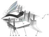
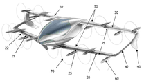
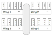
수직 이착륙 (VTOL) 항공기(10)가 개시된다. 바람직한 실시 예에서, 도면에 도시된 바와 같이, 두 쌍의 날개가 존재한다. 즉, 전방 날개(20,22) 및 후방 날개(30,32). 각각의 전방 날개(20,22)는 동체(24)의 측 방향으로 대향되는 영역에 부착된다. 마찬가지로, 각각의 후방 날개(30,32)는 동체(24)의 측 방향으로 대향되는 영역에 부착된다. 도면에 도시된 실시 예에서, 항공기(10)는 1인승 항공기(10)로 도시되어 있다. 그러나, 더 큰 다인승의 실시 예도 가능할 수 있다.A vertical takeoff and landing (VTOL)
도면에 도시된 실시 예에서, 전방 날개(20,22) 및 후방 날개(30,32)의 원단부는 연결되어, 두 쌍의 날개(20,22,30,32)는 박스형 날개 또는 폐쇄형 날개 구조를 규정한다.In the embodiment shown in the drawings, the
다른 실시 예에서(미도시), 전방 날개(20,22) 및 후방 날개(30,32)는 타이 바(tie bar)나 스트럿(strut)으로 연결된 스트럿 지주식 날개(strut braced wing)일 수 있다. 스트럿 지주식 날개는 일반적으로 기존 캔틸레버식 날개(cantilevered wing)보다 가볍다.In another embodiment (not shown), the
본 명세서에서 설명되는 VTOL 항공기(10)가 박스형 날개 또는 스트럿 지주식 항공기(10)이지만, 당업자라면 항공기(10)는 전방 날개(20,22) 및 후방 날개(30,32)가 분리되어 연결되지 않은 기존 캔틸레버식 날개 항공기일 수 있다는 점을 충분히 이해할 수 있을 것이다. 또한, 항공기(10)는 단지 단일 쌍의 날개만을 가질 수도 있다.Although the
도면을 참조하면, 전방 날개(20,22) 및 후방 날개(30,32)는 수직 방향으로 분리되어 있다.Referring to the drawings, the
도 2에 도시된 바와 같이, 후방 날개(30,32)의 팁 부분(40)은 아래쪽 혹은 뒤쪽으로 연장될 수 있다. 상기 윙 팁 부분, 또는 윙렛(40)은 윙 팁의 와류를 감소시킨다.As shown in Figure 2, the
다시 도 2를 참조하면, 각각의 윙렛(40)의 근위측은 인접한 전방 날개(20) 및 후방 날개(30)를 연결하는 연결 부재(42)에 연결된다. 추가적인 연결 부재(42)는 동체의 대향 측면 상의 인접한 전방 날개(22) 및 후방 날개(32)를 연결한다.Referring again to FIG. 2, the proximal side of each
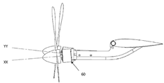
각 전방 날개(20,22) 및 후방 날개(30,32)는 고정된 리딩 엣지(25,35)를 포함한다. 리딩 엣지(25,35)는 에어포일(airfoil)의 일부의 형태로 곡선 윤곽을 가질 수 있다. 리딩 엣지는 회전하거나 또는 달리 움직이지 않는다.Each
각각의 고정된 리딩 엣지(25,35)의 후미측에서, 전방 날개(20,22) 및/또는 후방 날개(30,32)는 회동 방식으로(pivotally) 장착된 에일러론(보조익:aileron) 또는 제어 표면(50)을 포함한다. 각각의 제어 표면(50)은 이착륙을 위한 일반적 수직 구성(도 11C, 11D에 도시된 바와 같은) 및 전방 비행을 위한 일반적 수평 구성(도 11A, 11B에 도시된 바와 같은) 사이에서 회동될 수 있다.On the aft side of each fixed leading
제어 표면(50)은 날개(20,22,30,32)의 전체 길이를 따라 연속적으로 연장되는 단일 표면일 수 있다. 대안적으로, 각각의 날개(20,22,30,32)는 하나 이상의 독립적으로 회동 가능한 제어 표면(50)을 구비할 수 있어서, 상기 제어 표면(50)은 다른 제어 표면(50)과 무관하게 리딩 엣지(25,35)에 대해 회동할 수 있다.The
수직 이착륙 (VTOL) 항공기(10)는 복수의 전기 모터(60)를 포함할 수 있다. 각각의 모터(60)는 프로펠러 또는 로터(70)를 포함할 수 있다. 도면에 도시된 바와 같이, 각각의 모터(60)의 몸체부(62)는 일반적으로 고정된 리딩 엣지(25,35)의 전방에서, 이동 가능한 제어 표면(50)의 상부 표면 또는 하부 표면에 인접하게 장착된다. 제어 표면(50)은 수평 비행 모드(도 2) 및 수직 비행 모드(도 1) 모두에 대해 약 80 및 100도 사이의 범위, 바람직하게는 대략 90도의 범위에서 회전할 수 있다.The vertical take-off and landing (VTOL)
모터(60)는 고정된 리딩 엣지(25,35)보다 충분히 전방에 장착될 수 있어서, 로터 블레이드는 후방으로 접힐 수 있으며 윙 구조를 명확히 유지할 수 있다.The
모터(60) 및 제어 표면(50)에 대한 두 가지 가능한 장착 배열이 있을 수 있다.There can be two possible mounting arrangements for the
a) 각각의 모터(60)는 고정 리딩 엣지(25,35) 중 하나에 회동 방식으로 연결될 수 있고, 제어 표면(50)은 모터(60)의 몸체부(62)에 고정된다(예를 들어, 도 11C); 또는a) Each
b) 제어 표면(50)은 고정된 리딩 엣지(25,35) 중 하나에 회동 방식으로 연결될 수 있고, 상기 제어 표면은 모터(60)의 몸체부(62)에 고정된다.b) The
전기 모터(60)는 각각의 모터(60)의 로터가 대체로 수직한 회전 축을 갖는 제1 위치 및 각각의 모터(60)의 로터가 대체로 수평한 회전 축을 갖는 제2 위치 사이에서 제어 표면(50)과 함께 리딩 엣지(25,35)에 대해 각각 회동될 수 있다.The
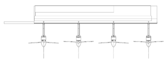
도 1 내지 도 6에 도시된 실시 예에서, 날개(20,22,30,32) 중 적어도 하나는 제어 표면(50)을 통과하는 평면을 기준으로 서로에 대해 오프셋 되는 제1 및 제2 모터(60)를 구비한다. 도면에 도시된 실시 예에서, 이것은 날개(20,22,30,32)의 대향하는 상부측 및 하부측 상에 모터(60)를 위치시킴으로써 달성된다. 도 1 내지 도 6에 도시된 실시 예에서, 각각의 날개는 4개의 전기 모터(60)를 구비한다. 즉, 2개의 전기 모터(60)는 날개(20,22,30,32) 위에 장착되고, 2개의 전기 모터는 날개(20,22,30,32)의 아래에 교대 방식의 구성으로 장착된다. 그러나, 도 14 및 도 15에 도시된 실시 예에서, 각각의 날개는 2개의 전기 모터(60)를 구비한다.In the embodiment shown in Figures 1-6, at least one of the
전기 모터(60)와 이들의 장착 파일론(pylon)은 회동 제어 표면(50)에 각각 장착된다. 전체 모터는 힌지 점(33)을 중심으로 회전한다. 4개의 모터(60)는 상이한 추력 선을 갖도록 장착된다. 특히, 2개의 모터(60)는 제어 표면(50)을 수평 방향으로 회전시키는 경향이 있는 추력 선을 가지며, 다른 2개의 모터는 날개(20,22,30,32)를 수직 방향으로 회전시키는 경향이 있는 추력 선을 가진다. 4개의 모터(60)가 모두 일제히 작동하면 모멘트가 상쇄되어, 수직 비행 모드에서의 안정화가 달성된다.The
도면 3 내지 6에 도시된 날개 조정 순서는 이륙 날개 위치와 전진 비행 날개 위치 간의 전환 시에 모터(60)와 제어 표면(50)의 경사 변화를 나타낸다. 이들 도면에 도시된 바와 같이, 리딩 엣지(25,35)는 고정식 및 비회동식이다. 그와 반대로, 모터(60)와 제어 표면(50)은 동시에 회동한다.The wing adjustment sequence shown in FIGS. 3 to 6 shows the inclination change of the
도 6을 참조하면, 날개가 전진 비행을 위해 최종 수평 위치에 도달하면, 리딩 엣지(25,35)와 제어 표면(50) 간의 결합에 의해 날개(20,22,30,32)는 더 이상 회동하지 않게 된다. 이는 날개(20,22,30,32) 및 제어 표면(50)이 보완적인 결합 표면을 갖기 때문에 발생한다.Referring to FIG. 6, when the wings reach the final horizontal position for forward flight, the
도 7 내지 도 10은 본 발명의 제2 실시 예를 나타낸다. 이 실시 예에서, 4개의 모터(60)는 각각 날개(20,22,30,32) 아래에 장착된다. 특히, 각각의 모터(60)는 날개(20,22,30,32) 아래의 위치에 힌지 방식으로 고정되고, 이는 하강 시 큰 각도의 기울기로 양력 계수를 추가로 증가시키고, 진동(buffet)을 감소시키는 리딩 엣지 슬롯(72)을 생성하는데 사용될 수 있다.7 to 10 show a second embodiment of the present invention. In this embodiment, four
리딩 엣지 슬롯(72)은 리딩 엣지(25,35) 및 틸팅 제어 표면(50) 간의 틈(gap)이다. 슬롯(72)은 도 3, 4 및 5에서 확인될 수 있으며, 도 6에서는 닫힌 위치 내에 존재한다. 상기 슬롯(72)은 또한 도 11A에서도 확인될 수 있다.The
도 8을 참조하면, 이러한 배열에서 모터들의 회전 축들은 평행하지 않다. 특히, 각각의 홀수 모터(60)는 제어 표면(50)에 대해 하방향으로 경사진 회전축(XX)를 가지며, 각각의 짝수 모터(60)는 제어 표면(50)에 대해 상방향으로 경사진 회전축(YY)를 가진다. 이러한 방식으로, 2개의 모터(60)는 제어 표면(50)을 시계 방향으로 회전시키는 경향의 추력 선을 가지며, 다른 2개의 모터는 제어 표면(50)을 반시계 방향으로 회전시키는 경향의 추력 선을 가진다. 모든 4개의 모터(60)가 동시에 작동하면 모멘트는 상쇄되고, 수직 비행 모드에서의 안정화가 달성된다.Referring to Figure 8, the rotation axes of the motors in this arrangement are not parallel. In particular, each
항공기(10)는 각각의 모터(60)에 개별적으로 조정된 전력 공급을 제공한다. 이는 각각의 모터에 상이한 전압이 전달되도록 허용하고, 따라서 좌우 회전과 같은 원하는 비행 조건을 달성하도록 각각의 모터에 의해 가변 전력 출력이 선택적으로 생성될 수 있다.The
또한, 모터(60)의 독립적인 전력은 모터(60)가 날개(20,22,30,32)의 트레일링 엣지(trailing edges) 상에 위치된 제어 표면(50)을 기울이는데 사용될 수 있도록 한다.In addition, the independent power of the
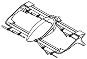
도 11A 내지 도 11D는 날개(20,22,30,32) 중 하나의 아랫면에 장착된 모터(60)의 개략도이다. 힌지 플레이트(28)는 고정된 리딩 엣지(25,35)에 연결되고, 아래쪽으로 연장된다. 모터(60)는 힌지 지점(33)에서 힌지 플레이트(28)에 회동 방식으로 연결된다. 프로펠러(70) 및 파일론 구조는 힌지 지점(33)을 중심으로 회전하는 제어 표면(50)에 고정되어 있다.11A to 11D are schematic views of the
날개 아랫면에 장착된 모터(60)를 구비한 상기 실시 예에서, 도 11A 내지 도 11D에 도시된 날개 조정 순서는 수직 이륙 날개 위치 및 수평 전진 비행 날개 위치 간의 전환 시에 모터(60) 및 제어 표면(50)의 경사 변화를 나타낸다. 제1 실시 예와 동일한 방식으로, 리딩 엣지(25,35)는 고정식 및 비회동식이고, 모터(60) 및 제어 표면(50)은 동시에 회동된다.In the above embodiment with the
도 12A 내지 12D는 도 7 내지 도 11D 중 어느 하나의 날개 배열에 대한 수직 및 수평 간의 전환을 도시한 개략적인 단면도이다. 도 12A 내지 12D는 또한 각각의 날개 상의 인접한 모터의 추력 선이 평행하지 않은 것을 나타내며, 이것은 힌지 지점(33)을 중심으로 모멘트를 발생시켜, 제어 표면(50)에 대해 회전하도록 선택적으로 사용될 수 있다.12A to 12D are schematic cross-sectional views showing a transition between vertical and horizontal for one of the wing arrangements of FIGS. 7 to 11D. 12A-12D also show that the thrust lines of adjacent motors on each wing are non-parallel, which can be used selectively to rotate about the
도면에 도시된 바람직한 실시 예에서, 2개 또는 4개의 모터(60)가 각각의 날개(20,22,30,32)에 장착될 수 있다. 하지만 추가적인 모터(60)도 항공기(10), 예를 들어, 날개(20,22,30,32), 동체(24)의 기수(nose) 또는 날개 연결 부재(42) 상에 장착될 수 있다.In the preferred embodiment shown in the figures, two or four
일 실시 예에서, 힌지 메커니즘은 구조적 무게를 더욱 감소시키는 모터 포드(motor pod) 구조로 통합될 수 있다. 추가적으로 가능한 개선은 다수의 모터 포드가 있는 경우, 각각의 포드가 힌지 베어링을 수용하는 것이다.In one embodiment, the hinge mechanism can be incorporated into a motor pod structure that further reduces structural weight. An additional possible improvement is that if there are multiple motor pods, each pod accommodates a hinge bearing.
도 10을 참조하면, 모터(60)의 로터(70) 블레이드(blade)는 사용하지 않을 때 아래쪽으로 접힐 수 있다. 또한, 로터 블레이드(70)의 일부는 전진 비행 모드에서 아래쪽 및 뒤쪽으로 접힐 수 있는데, 그 이유는 이착륙과 비교하여 전진 비행 모드에서 일반적으로 더 적은 추진력이 요구되기 때문이다.Referring to FIG. 10, the
종래의 틸트 윙 항공기는 날개를 기울이기 위해 액추에이터가 필요하다. 반면에, 본 명세서에 개시된 VTOL 항공기(10)의 실시 예는 제어 표면(50)을 회전시키기 위해 모터 추력을 사용한다. 이것은 모터를 윙 틸트 축의 양측 상에(즉, 날개의 위와 아래에) 장착되는 모터를 구비하거나, 또는 대안적으로 도 7에 도시된 바와 같이 다른 모터와 비교하여, 각도 방향으로 오프셋된 상이한 추력 선을 갖도록 나머지 다른 모터에 대해 각도 방향으로 경사진 일부 모터를 구비함으로써 달성될 수 있다. 작동이 이하에서 기술된다.Conventional tilt wing aircraft require an actuator to tilt the wing. On the other hand, embodiments of the
모터(60)는 바람직하게는 스위칭 주파수를 변경함으로써 속도를 변화시키는 브러시리스 DC 모터이다. 이러한 스위칭 주파수는 제어 시스템(90)에서 전자 속도 제어기(electronic speed controllers, ESC)에 의해 제어된다. 모터(60)는 실제로는 영구 자석 AC 모터이지만, ESC로부터의 입력은 DC이므로 일반적으로 브러시리스 DC라고 지칭된다. 모터(60) 작동은 ESC로부터의 주파수 입력이 더 높아지면 프로펠러 속도가 더 빨라지고, ESC로부터의 주파수 입력이 더 낮아지면 프로펠러 속도가 더 느려진다.The
실제로, 스위칭 주파수가 동일하면, 모멘트는 균형을 이룰 것이다.Indeed, if the switching frequencies are the same, the moment will be balanced.
제1 실시 예 - 날개 위와 아래에 장착된 모터First embodiment-motor mounted above and below the wing
도 1 내지 도 6에 도시된 실시 예를 참조하면, 날개의 제어 표면(50) 위에 위치된 전기 모터(60)의 회전 속도를 증가시킴으로써, 제어 시스템은 상부 프로펠러(70)에 의해 생성된 추력을 증가시킬 수 있다. 동시에, 날개의 제어 표면(50) 아래에 위치한 모터(60)의 속도를 감소시키면, 하부 프로펠러(70)에 의해 생성된 추력이 감소된다. 결과적으로, 회전 모멘트가 생성되어, 대체로 수평한, 전방 비행 모드로 제어 표면(50)을 회전시킨다.1 to 6, by increasing the rotational speed of the
반면에, 날개의 제어 표면(50) 위에 위치된 전기 모터(60)의 속도를 감소시키고 날개의 제어 표면(50) 아래에 위치된 전기 모터(60)의 속도를 증가시킴으로써, 회전 모멘트를 생성하여 수직(즉, 이착륙) 구성으로 제어 표면(50)을 회전시킬 수 있다.On the other hand, by reducing the speed of the
모터(60)는 제어 소프트웨어의 혼합 알고리즘을 사용하여 제어되어, 날개 해당 세그먼트 상의 모든 모터(60)의 총 출력이 안정적인 비행을 위해 필요한 총 추력을 생성하는 것을 보장하면서도, 여전히 명령에 의해 날개를 수직에서 수평으로 그리고 뒤로 기울일 수 있다.The
브레이크 또는 클램핑 장치 또는 소형 액추에이터가 제어 표면(50)을 원하는 수직 또는 수평 구성으로 유지하는데 사용된다.A brake or clamping device or small actuator is used to keep the
제2 실시 예 - 각추력 벡터 오프셋(angular thrust vector offset)을 갖도록 장착된 모터Embodiment 2-Motor mounted to have angular thrust vector offset
도 7 내지 도 13에 도시된 실시 예를 참조하면, 하향 경사 추력 선(XX)을 갖는 전기 모터(60)의 회전 속도를 증가시킴으로써 제어 시스템은 상부 프로펠러(70)에 의해 생성된 추력을 증가시킬 수 있다. 동시에, 상향 경사 추력 선(YY)를 갖는 2개의 모터(60)의 속도를 감소시키면, 이들 프로펠러(70)에 의해 생성된 추력이 감소한다. 결과적으로, 회전 모멘트가 생성되어, 대체로 수평한, 전방 비행 모드로 제어 표면(50)을 회전시킨다.7 to 13, the control system increases the thrust generated by the
그와 반대로, 하향 경사 추력선(XX)을 갖는 전기 모터(60)의 속도를 감소시키고, 상향 경사 추력 선(YY)을 갖는 전기 모터(60)의 속도를 증가시킴으로써, 회전 모멘트를 생성하여 수직(즉, 이착륙) 구성으로 제어 표면(50)을 회전시킬 수 있다.On the contrary, by reducing the speed of the
항공기(10)의 추가적인 실시 예는 제어 표면(50) 당 4, 6 또는 2n (n=1,2,3,4 …)개의 모터(60)를 구비하여 틸트 메커니즘이 여유(redundancy)를 갖게 되고, 임의의 단일 모터가 고장이 나더라도 날개 회전을 방해하지 않는다.A further embodiment of the
유리한 측면은, 항공기(10)의 실시 예가 틸트 윙 구성 항공기(10)의 날개를 회전시키기 위해 크거나 무거운 액추에이터가 불필요하다는 점이다. 또한, 구성 요소의 수가 잠재적으로 감소하여 시스템 신뢰성을 증가시킨다.An advantageous aspect is that embodiments of the
하나의 예시가 기술된다. 도 7 내지 도 13을 참조하면, 도시된 실시 예는 날개(20,22,30,32) 당 4개의 모터를 구비하여 총 16개의 모터(60)를 구비한다.One example is described. Referring to FIGS. 7 to 13, the illustrated embodiment includes four motors per
T1 = 프로펠러 & 모터 1의 추력 (P1)T 1 = thrust of propeller & motor 1 (P 1 )
T2 = 프로펠러 & 모터 2의 추력 (P2)T 2 = thrust of propeller & motor 2 (P 2 )
Tn = 프로펠러 & 모터 3의 추력 (Pn)T n = thrust of propeller & motor 3 (P n )
T16 = 프로펠러 & 모터 16의 추력 (P16)T 16 = thrust of propeller & motor 16 (P 16 )
모터(60)가 수직 축 구성(예를 들어, 도 12A)인 경우,If the
총 정지 비행 추력 = T1 + T2 + T3 + … + T16 Total static flight thrust = T 1 + T 2 + T 3 +… + T 16
균형 정지 비행 무게 = 질량 * g (중력 가속도)Balanced static flight weight = mass * g (gravity acceleration)
W = T1+ T2 + T3 + … + T16 W = T 1 + T 2 + T 3 +… + T 16
각각의 모터(60)에 의해 발생된 추력은 각각의 프로펠러(70)의 속도를 증가 또는 감소시킴으로써 제어 시스템에 의해 변화될 수 있고, 이는 모터(60)의 회전 속도를 증가 또는 감소시키는 모터 전자 속도 제어기(electronic speed controller, ESC)에 신호를 전송함으로써 달성된다. 대안적으로, 가변 피치 프로펠러가 사용될 수 있으며, 프로펠러 상의 피치를 가변시켜 추력을 변화시킨다.The thrust generated by each
날개 1의 추력 = Tw1= T1+ T2 + T3 + T4 Thrust of
날개 2의 추력 = Tw2= T5+ T6 + T7 + T8 Thrust of
날개 3의 추력 = Tw3= T9+ T10 + T11 + T12 Thrust of
날개 4의 추력 = Tw4= T13+ T14 + T15 + T16 Thrust of
정상 상태 정지 비행 시:In steady state flight:
W = Tw1+ Tw2 + Tw3 + Tw4 W = T w1 + T w2 + T w3 + T w4
종래의 멀티 로터 안정화 알고리즘을 사용하여, 각각의 모터(60)의 속도는 장애(disturbance)에 대해 안정화되도록 가변되고 차동 추력은 항공기(10)를 피치 및 롤링하도록 사용된다.Using conventional multi-rotor stabilization algorithms, the speed of each
정지 비행 모드에서 날개(20,22,30,32)는 또 다른 메커니즘을 사용하여 자유롭거나 클램핑될 수 있다.In the stationary flight mode, the
유리한 측면은, 항공기(10)가 각각의 모터(60)에 대해 더 작게 분산된 힌지 베어링을 허용하고, 이는 여유가 될 수 있으며, 훨씬 더 작은 직경일 수 있다(따라서 더 가벼울 수 있다)는 점이다.The advantageous aspect is that the
본 발명은 하강하는 동안 틸트 윙 항공기가 겪게되는 와류를 엄청나게 감소시키는 슬롯형 리딩 엣지(slotted leading edge)를 제공할 수 있다.The present invention can provide a slotted leading edge that greatly reduces the vortex experienced by a tilt wing aircraft during descent.
추가적인 전기 모터(미도시)가 추가적인 양력 및/또는 전진 속도를 생성하기 위해 동체와 같은, 날개 이외의 구조물에 장착될 수 있다.Additional electric motors (not shown) can be mounted to structures other than the wing, such as the fuselage, to generate additional lift and / or advance speed.
유리한 측면은, 박스형 날개 구조가 동일한 크기의 기존 날개보다 공기 역학적으로 더 효율적이고, 구조적으로 더 효율적일 수 있다(따라서 더 가볍다)는 점이다.The advantageous aspect is that the box-shaped wing structure is aerodynamically more efficient and can be structurally more efficient (and therefore lighter) than a conventional wing of the same size.
유리한 측면은, 박스형 날개 구조는 추가적인 강성(rigidity)을 제공한다.Advantageous aspects, the box-shaped wing structure provides additional rigidity.
유리한 측면은, 항공기(10)가 종래의 틸트 윙 항공기와 비교하여 필요한 베어링 및 틸트 구조의 무게를 감소시킨다. 그 이유는 기존 틸트 윙은 회전하는 견고한 구조를 갖는 단일의 대형 베어링 쌍(항공기 동체의 한면 상에 하나)이 필요하기 때문이다.An advantageous aspect is that the
본 발명은 특정 예시를 참조하여 설명되었지만, 본 발명 기술 분야의 통상의 기술자라면 본 발명이 다수의 다른 형태로 구현될 수 있다는 점을 이해할 수 있을 것이다.Although the invention has been described with reference to specific examples, those skilled in the art will appreciate that the invention may be implemented in many different forms.
Claims (11)
동체;
상기 동체의 대향 측면에 장착된 제1 및 제2 전방 날개-여기서 제1 및 제2 전방 날개는 각각 고정된 리딩 엣지(leading edge) 및 대체로 수평한 회동(pivot) 축을 중심으로 회동되는 후미 제어 표면을 구비함-;
각각이 로터를 구비하는 제1 및 제2 전기 모터-여기서 상기 제1 및 제2 전기 모터는 상기 각각의 날개에 장착되고, 상기 로터는 각각의 로터가 대체로 수직한 회전 축을 갖는 제1 위치 및 대체로 수평한 회전 축을 갖는 제2 위치 사이에서 상기 제어 표면과 함께 회동함-;
각각의 모터를 제어하는 제어 시스템;
을 포함하고,
상기 제어 시스템은 상기 회동 축을 중심으로 상기 제어 표면을 회동시키도록 회전 모멘트를 생성하기 위해 상기 제1 및 제2 전기 모터를 다른 회전 속도에서 선택적으로 작동하도록 구성되는 것을 특징으로 하는 수직 이착륙 (VTOL) 항공기.For vertical take-off and landing (VTOL) aircraft,
fuselage;
First and second front vanes mounted on opposite sides of the fuselage, wherein the first and second front vanes are respectively a fixed leading edge and a rear control surface pivoted about a generally horizontal pivot axis. Equipped with-;
First and second electric motors, each having a rotor, wherein the first and second electric motors are mounted to the respective blades, the rotors having a first position and generally a rotational position in which each rotor has a generally vertical rotational axis. Rotating with the control surface between a second position having a horizontal axis of rotation;
A control system that controls each motor;
Including,
The control system is configured to selectively operate the first and second electric motors at different rotational speeds to generate a rotational moment to rotate the control surface around the rotational axis (VTOL). aircraft.
상기 제1 전기 모터의 추력 선(thrust line)은 상기 제2 전기 모터의 추력 선에 대해 각도 방향으로 오프셋되는 것을 특징으로 하는 수직 이착륙 (VTOL) 항공기.According to claim 1,
A vertical takeoff and landing (VTOL) aircraft, characterized in that the thrust line of the first electric motor is offset in an angular direction with respect to the thrust line of the second electric motor.
상기 제1 전기 모터는 상기 제어 표면 위에 위치되는 로터를 구비하고, 상기 제2 모터는 상기 제어 표면 아래에 위치되는 로터를 구비하여, 상기 제1 전기 모터의 추력 선은 상기 제2 전기 모터의 추력 선에 대해 대체로 평행하게 오프셋 되는 것을 특징으로 하는 수직 이착륙 (VTOL) 항공기.According to claim 1,
The first electric motor has a rotor positioned over the control surface, and the second motor has a rotor positioned below the control surface, so that the thrust line of the first electric motor is the thrust of the second electric motor Vertical take-off and landing (VTOL) aircraft, characterized by being offset substantially parallel to the line.
상기 제1 모터는 상기 제1 위치 및 상기 제2 위치 사이에서 상기 제어 표면을 움직이도록 하는 명령에 응답하여, 상기 제어 시스템에 의해 상기 제2 모터보다 더 빠른 회전 속도에서 작동되고,
상기 제1 모터는 상기 제2 위치 및 상기 제1 위치 사이에서 상기 제어 표면을 움직이도록 하는 명령에 응답하여, 상기 제어 시스템에 의해 상기 제2 모터보다 더 느린 회전 속도에서 작동되는 것을 특징으로 하는 수직 이착륙 (VTOL) 항공기.The method according to any one of claims 1 to 3,
The first motor is operated by the control system at a faster rotational speed than the second motor in response to a command to move the control surface between the first position and the second position,
Wherein the first motor is operated at a lower rotational speed than the second motor by the control system in response to a command to move the control surface between the second position and the first position. Take-off and landing (VTOL) aircraft.
상기 각각의 날개는 각각이 로터를 구비하는 적어도 2개의 전기 모터를 구비하고, 쌍으로 배열되는 상기 로터는 쌍을 이룬 모터가 대체로 동일한 회전 속도로 회전할 때 임의의 회전 모멘트를 상쇄시키는 추력 선을 갖는 것을 특징으로 하는 수직 이착륙 (VTOL) 항공기.The method according to any one of claims 1 to 4,
Each of the blades has at least two electric motors, each of which has a rotor, and the rotors arranged in pairs generate a thrust line that offsets any rotational moment when the paired motors rotate at substantially the same rotational speed. VTOL aircraft characterized by having.
정지 비행 모드에서, 상기 제어 시스템은 항공기 및 유효 탑재량의 총 질량에 중력 가속도를 곱한 값과 동일한 전체 모터의 결합된 추력을 발생시키는 적절한 속도에서 상기 각각의 모터를 회전시키도록 구성되는 것을 특징으로 하는 수직 이착륙 (VTOL) 항공기.The method according to any one of claims 1 to 5,
In stationary flight mode, the control system is configured to rotate each of the motors at an appropriate speed to generate the combined thrust of the entire motor equal to the total mass of the aircraft and effective payload multiplied by gravitational acceleration. Vertical take-off and landing (VTOL) aircraft.
원하는 상기 제1 위치 및 상기 제2 위치에서 상기 제어 표면을 유지하기 위한 브레이크, 소형 액추에이터 또는 클램핑 장치를 추가적으로 포함하는 것을 특징으로 하는 수직 이착륙 (VTOL) 항공기.The method according to any one of claims 1 to 6,
Vertical takeoff and landing (VTOL) aircraft, further comprising a brake, a small actuator or a clamping device for holding the control surface in the desired first and second positions.
상기 브레이크 또는 클램핑 장치는 상기 제어 시스템에 의해 작동되는 것을 특징으로 하는 수직 이착륙 (VTOL) 항공기.The method of claim 7,
The brake or clamping device is operated by the control system, characterized in that the vertical take-off and landing (VTOL) aircraft.
상기 동체의 대향 측면에 장착된 제1 및 제2 후방 날개를 추가적으로 포함하고,
상기 동체로부터 가장 먼 각각의 전방 날개의 원단부는 연결 부재를 갖는 인접한 후방 날개의 원단부에 연결되어 박스형 날개 구조를 규정하는 것을 특징으로 하는 수직 이착륙 (VTOL) 항공기.The method according to any one of claims 1 to 8,
It further includes first and second rear wings mounted on opposite sides of the fuselage,
A vertical takeoff and landing (VTOL) aircraft characterized in that the distal end of each front wing farthest from the fuselage is connected to the distal end of an adjacent rear wing having a connecting member to define a box-shaped wing structure.
동체;
상기 동체의 대향 측면에 장착된 제1 및 제2 전방 날개-여기서 상기 제1 및 제2 전방 날개는 각각 고정된 리딩 엣지 및 대체로 수평한 회동(pivot) 축을 중심으로 회동되는 후미 제어 표면을 구비함-;
제1 가변 피치 프로펠러를 구비하는 제1 전기 모터 및 제2 가변 피치 프로펠러를 구비하는 제2 전기 모터-여기서 상기 제1 및 제2 모터는 상기 각각의 날개에 장착되고, 상기 제1 및 제2 프로펠러는 각각의 프로펠러가 대체로 수직한 회전 축을 갖는 제1 위치 및 대체로 수평한 회전 축을 갖는 제2 위치 사이에서 상기 제어 표면과 함께 회동함-;
상기 각각의 가변 피치 프로펠러의 회전 속도 및/또는 블레이드(blade) 피치를 제어하기 위한 제어 시스템;
을 포함하고,
상기 제어 시스템은 상기 회동 축을 중심으로 상기 제어 표면이 회동하도록 회전 모멘트를 생성하기 위해 상기 제2 프로펠러에 대한 상기 제1 프로펠러의 피치를 변화시키도록 구성되는 것을 특징으로 하는 수직 이착륙 (VTOL) 항공기.For vertical take-off and landing (VTOL) aircraft,
fuselage;
First and second front vanes mounted on opposite sides of the fuselage, wherein the first and second front vanes each have a fixed leading edge and an aft control surface that rotates about a generally horizontal pivot axis. -;
A first electric motor having a first variable pitch propeller and a second electric motor having a second variable pitch propeller, wherein the first and second motors are mounted on the respective wings, and the first and second propellers Is that each propeller rotates with the control surface between a first position with a generally vertical axis of rotation and a second position with a generally horizontal axis of rotation;
A control system for controlling the rotational speed and / or blade pitch of each variable pitch propeller;
Including,
The control system is configured to change the pitch of the first propeller relative to the second propeller to create a rotational moment such that the control surface rotates about the axis of rotation. A vertical takeoff and landing (VTOL) aircraft.
상기 모터는 상기 제어 시스템의 전자 속도 제어기로부터의 스위칭 주파수 변화에 응답하여 속도를 변화시키는 브러시리스 DC 모터인 것을 특징으로 하는 수직 이착륙 (VTOL) 항공기.The method according to any one of claims 1 to 10,
The motor is a brushless DC motor that changes speed in response to a change in switching frequency from an electronic speed controller of the control system.
Applications Claiming Priority (7)
| Application Number | Priority Date | Filing Date | Title |
|---|---|---|---|
| AU2017903864A AU2017903864A0 (en) | 2017-09-22 | Wing tilt mechanism for electric vertical take-off and landing (VTOL) aircraft | |
| AU2017903864 | 2017-09-22 | ||
| AU2017904036A AU2017904036A0 (en) | 2017-10-06 | Wing tilt actuation system for electric vertical take-off and landing (VTOL) aircraft | |
| AU2017904036 | 2017-10-06 | ||
| AU2018901154A AU2018901154A0 (en) | 2018-04-06 | Wing tilt mechanism for electric vertical take-off and landing (VTOL) aircraft | |
| AU2018901154 | 2018-04-06 | ||
| PCT/AU2018/050962 WO2019056052A1 (en) | 2017-09-22 | 2018-09-06 | Wing tilt actuation system for electric vertical take-off and landing (vtol) aircraft |
Publications (2)
| Publication Number | Publication Date |
|---|---|
| KR20200057057A true KR20200057057A (en) | 2020-05-25 |
| KR102650998B1 KR102650998B1 (en) | 2024-03-26 |
Family
ID=65809451
Family Applications (2)
| Application Number | Title | Priority Date | Filing Date |
|---|---|---|---|
| KR1020207011614A KR102650998B1 (en) | 2017-09-22 | 2018-09-06 | Wing tilt drive system for electric vertical takeoff and landing (VTOL) aircraft |
| KR1020207011615A KR102627026B1 (en) | 2017-09-22 | 2018-09-06 | Wing tilt drive system for electric vertical takeoff and landing (VTOL) aircraft |
Family Applications After (1)
| Application Number | Title | Priority Date | Filing Date |
|---|---|---|---|
| KR1020207011615A KR102627026B1 (en) | 2017-09-22 | 2018-09-06 | Wing tilt drive system for electric vertical takeoff and landing (VTOL) aircraft |
Country Status (18)
| Country | Link |
|---|---|
| US (2) | US20200223542A1 (en) |
| EP (3) | EP3684687B1 (en) |
| JP (3) | JP7174054B2 (en) |
| KR (2) | KR102650998B1 (en) |
| CN (2) | CN111225853B (en) |
| AU (4) | AU2018337069B2 (en) |
| BR (2) | BR112020005611B1 (en) |
| CA (2) | CA3075429A1 (en) |
| ES (1) | ES2953004T3 (en) |
| IL (2) | IL273314B2 (en) |
| MX (2) | MX2020003022A (en) |
| PH (2) | PH12020500507A1 (en) |
| PL (1) | PL3684687T3 (en) |
| RU (2) | RU2766634C2 (en) |
| SG (2) | SG11202002180RA (en) |
| SI (1) | SI3684687T1 (en) |
| WO (2) | WO2019056053A1 (en) |
| ZA (2) | ZA202001684B (en) |
Cited By (1)
| Publication number | Priority date | Publication date | Assignee | Title |
|---|---|---|---|---|
| KR102622742B1 (en) | 2023-05-09 | 2024-01-08 | 함명래 | Hybrid vertical take-off and landing aircraft with improved flight stability |
Families Citing this family (25)
| Publication number | Priority date | Publication date | Assignee | Title |
|---|---|---|---|---|
| US9694911B2 (en) * | 2014-03-18 | 2017-07-04 | Joby Aviation, Inc. | Aerodynamically efficient lightweight vertical take-off and landing aircraft with pivoting rotors and stowing rotor blades |
| CN112368208A (en) | 2018-05-31 | 2021-02-12 | 杰欧比飞行有限公司 | Electric power system architecture and fault-tolerant VTOL (virtual volume on-board) aircraft using same |
| US20220169380A1 (en) * | 2018-06-23 | 2022-06-02 | Behrang Mehrgan | Vtol tail sitting aircraft with rotor blown nonplanar wing configuration |
| US10710741B2 (en) | 2018-07-02 | 2020-07-14 | Joby Aero, Inc. | System and method for airspeed determination |
| EP3853736A4 (en) | 2018-09-17 | 2022-11-16 | Joby Aero, Inc. | Aircraft control system |
| WO2020069582A1 (en) * | 2018-10-02 | 2020-04-09 | Embraer S.A. | Vertical and short takeoff and landing (vstol) aircraft |
| WO2020118310A1 (en) | 2018-12-07 | 2020-06-11 | Joby Aero, Inc. | Rotary airfoil and design method therefor |
| US10983534B2 (en) | 2018-12-07 | 2021-04-20 | Joby Aero, Inc. | Aircraft control system and method |
| WO2020132332A1 (en) | 2018-12-19 | 2020-06-25 | Joby Aero, Inc. | Vehicle navigation system |
| KR20240043816A (en) | 2019-04-23 | 2024-04-03 | 조비 에어로, 인크. | Battery thermal management system and method |
| US11230384B2 (en) | 2019-04-23 | 2022-01-25 | Joby Aero, Inc. | Vehicle cabin thermal management system and method |
| CN114423679A (en) | 2019-04-25 | 2022-04-29 | 杰欧比飞行有限公司 | Vertical take-off and landing aircraft |
| USD933528S1 (en) * | 2019-04-30 | 2021-10-19 | Katla Aero AB | Aircraft |
| JP2022534294A (en) * | 2019-05-29 | 2022-07-28 | クラフト エアロスペース テクノロジーズ, インコーポレイテッド | Novel aircraft design using tandem wings and distributed propulsion systems |
| GB2601453B (en) * | 2019-07-18 | 2023-05-03 | Gkn Aerospace Services Ltd | An aircraft |
| GB2585864B (en) * | 2019-07-18 | 2022-04-27 | Gkn Aerospace Services Ltd | An aircraft |
| US11097839B2 (en) * | 2019-10-09 | 2021-08-24 | Kitty Hawk Corporation | Hybrid power systems for different modes of flight |
| GB202007673D0 (en) * | 2020-05-22 | 2020-07-08 | Univ Nelson Mandela Metropolitan | A vertical take-off and landing aircraft, methods and systems for controlling a vertical take-off and landing aircraft |
| WO2022056597A1 (en) * | 2020-09-18 | 2022-03-24 | AMSL Innovations Pty Ltd | Aircraft structure |
| US20220402603A1 (en) * | 2021-06-22 | 2022-12-22 | Kitty Hawk Corporation | Vehicle with tractor tiltrotors and pusher tiltrotors |
| WO2023282789A1 (en) * | 2021-07-06 | 2023-01-12 | Владимир Анатольевич ПЕТРОВ | Vertical take-off and landing aircraft |
| CN113353254B (en) * | 2021-07-14 | 2023-02-28 | 空中舞者(威海)航空动力技术有限公司 | Vertical take-off and landing gyroplane |
| CN114084344A (en) * | 2021-08-23 | 2022-02-25 | 上海新云彩航空科技有限责任公司 | Multi-shaft rotor aircraft with power wheel type undercarriage |
| CN114313251B (en) * | 2022-03-03 | 2022-06-21 | 天津斑斓航空科技有限公司 | Combined type aircraft active tilting structure and aircraft |
| UA152017U (en) * | 2022-09-06 | 2022-10-12 | Євген Олександрович Кононихін | Vertical takeoff and landing aircraft with a closed wing |
Citations (4)
| Publication number | Priority date | Publication date | Assignee | Title |
|---|---|---|---|---|
| JP2005168222A (en) * | 2003-12-04 | 2005-06-23 | Tokyo R & D Co Ltd | Motor drive circuit |
| US20050178879A1 (en) * | 2004-01-15 | 2005-08-18 | Youbin Mao | VTOL tailsitter flying wing |
| WO2016135697A1 (en) * | 2015-02-27 | 2016-09-01 | Skybox Engineering S.R.L. | Tiltrotor with double mobile wing |
| US20160288903A1 (en) * | 2015-03-24 | 2016-10-06 | U.S.A. As Represented By The Administrator Of The National Aeronautics And Space Administration | Aerodynamically Actuated Thrust Vectoring Devices |
Family Cites Families (31)
| Publication number | Priority date | Publication date | Assignee | Title |
|---|---|---|---|---|
| US1498412A (en) * | 1920-02-18 | 1924-06-17 | Whiteside Howard Austin | Helico-plane |
| US3181810A (en) * | 1961-02-27 | 1965-05-04 | Curtiss Wright Corp | Attitude control system for vtol aircraft |
| FR94023E (en) * | 1967-05-24 | 1969-06-20 | Bertin & Cie | Lift system or propulsion lift for aircraft. |
| US5046684A (en) * | 1989-02-09 | 1991-09-10 | Julian Wolkovitch | Airplane with braced wings and pivoting propulsion devices |
| RU2097272C1 (en) * | 1993-12-30 | 1997-11-27 | Анатолий Васильевич Бобров | Ecological hybrid vertical takeoff and landing flying vehicle with storage for helium used in it |
| US5823468A (en) * | 1995-10-24 | 1998-10-20 | Bothe; Hans-Jurgen | Hybrid aircraft |
| ITFI20030043A1 (en) * | 2003-02-19 | 2004-08-20 | Aldo Frediani | TWO-LEVEL WINGS AIRCRAFT WITH HIGH STATIC STABILITY |
| US7118066B2 (en) * | 2004-07-22 | 2006-10-10 | Norman Carter Allen | Tall V/STOL aircraft |
| CN1907806A (en) * | 2005-08-02 | 2007-02-07 | 韩培洲 | helicopter with tilted front rotary wing |
| US7871033B2 (en) * | 2008-04-11 | 2011-01-18 | Karem Aircraft, Inc | Tilt actuation for a rotorcraft |
| JP2010057314A (en) | 2008-08-29 | 2010-03-11 | Kyocera Mita Corp | Motor control device and image forming apparatus |
| US8733690B2 (en) * | 2009-08-24 | 2014-05-27 | Joby Aviation, Inc. | Lightweight vertical take-off and landing aircraft and flight control paradigm using thrust differentials |
| WO2012141736A1 (en) | 2010-10-06 | 2012-10-18 | Shaw Donlad Orval | Aircraft with wings and movable propellers |
| DE202012013513U1 (en) * | 2012-07-27 | 2017-05-12 | Jonathan Hesselbarth | Vertical airplane |
| US10071801B2 (en) * | 2013-08-13 | 2018-09-11 | The United States Of America As Represented By The Administrator Of Nasa | Tri-rotor aircraft capable of vertical takeoff and landing and transitioning to forward flight |
| DE102013109392A1 (en) | 2013-08-29 | 2015-03-05 | Airbus Defence and Space GmbH | Fast-flying, vertically launchable aircraft |
| CN112061389A (en) * | 2014-03-18 | 2020-12-11 | 杰欧比飞行有限公司 | Pneumatically efficient lightweight vertical takeoff and landing aircraft with pivoting rotors and furled rotor blades |
| JP6632542B2 (en) * | 2014-03-18 | 2020-01-22 | ジョビー エイビエイション インクJoby Aviation, Inc. | Aerodynamically efficient lightweight vertical take-off and landing aircraft with swirling rotor blades and contained rotor blades |
| US10625852B2 (en) * | 2014-03-18 | 2020-04-21 | Joby Aero, Inc. | Aerodynamically efficient lightweight vertical take-off and landing aircraft with pivoting rotors and stowing rotor blades |
| US9694911B2 (en) * | 2014-03-18 | 2017-07-04 | Joby Aviation, Inc. | Aerodynamically efficient lightweight vertical take-off and landing aircraft with pivoting rotors and stowing rotor blades |
| GB2526517A (en) * | 2014-03-27 | 2015-12-02 | Malloy Aeronautics Ltd | Rotor-Lift Aircraft |
| RU2577931C1 (en) * | 2015-01-13 | 2016-03-20 | Дмитрий Сергеевич Дуров | Hybrid short takeoff and landing aircraft |
| DE102015207445B4 (en) | 2015-04-23 | 2023-08-17 | Lilium GmbH | Aerofoil for an aircraft and aircraft |
| DE102015006511A1 (en) | 2015-05-26 | 2016-12-01 | Airbus Defence and Space GmbH | Vertical launching aircraft |
| US20170297699A1 (en) * | 2015-10-30 | 2017-10-19 | Sikorsky Aircraft Corporation | Quad rotor tail-sitter aircraft with rotor blown wing (rbw) configuration |
| WO2017096478A1 (en) | 2015-12-11 | 2017-06-15 | Coriolis Games Corporation | Hybrid multicopter and fixed wing aerial vehicle |
| CN105882961A (en) * | 2016-04-13 | 2016-08-24 | 邓阳平 | High-speed aircraft capable of taking off and landing vertically as well as control method of high-speed aircraft |
| CN105730692B (en) * | 2016-04-19 | 2018-04-17 | 北京航空航天大学 | One kind is verted the long endurance combined type aircraft of quadrotor |
| CA3024611A1 (en) * | 2016-05-18 | 2017-11-23 | A^3 By Airbus Llc | Vertical takeoff and landing aircraft with tilted-wing configurations |
| EP3464064B1 (en) | 2016-06-03 | 2022-11-16 | AeroVironment, Inc. | Vertical take-off and landing (vtol) winged air vehicle with complementary angled rotors |
| US10807707B1 (en) * | 2016-09-15 | 2020-10-20 | Draganfly Innovations Inc. | Vertical take-off and landing (VTOL) aircraft having variable center of gravity |
-
2018
- 2018-09-06 WO PCT/AU2018/050963 patent/WO2019056053A1/en unknown
- 2018-09-06 AU AU2018337069A patent/AU2018337069B2/en active Active
- 2018-09-06 SI SI201830971T patent/SI3684687T1/en unknown
- 2018-09-06 JP JP2020537809A patent/JP7174054B2/en active Active
- 2018-09-06 US US16/647,817 patent/US20200223542A1/en active Pending
- 2018-09-06 BR BR112020005611-1A patent/BR112020005611B1/en active IP Right Grant
- 2018-09-06 US US16/647,824 patent/US11535371B2/en active Active
- 2018-09-06 BR BR112020005719-3A patent/BR112020005719A2/en active Search and Examination
- 2018-09-06 EP EP18859252.1A patent/EP3684687B1/en active Active
- 2018-09-06 CA CA3075429A patent/CA3075429A1/en active Pending
- 2018-09-06 IL IL273314A patent/IL273314B2/en unknown
- 2018-09-06 RU RU2020110832A patent/RU2766634C2/en active
- 2018-09-06 KR KR1020207011614A patent/KR102650998B1/en active IP Right Grant
- 2018-09-06 JP JP2020537810A patent/JP7232834B2/en active Active
- 2018-09-06 EP EP23164413.9A patent/EP4219303A1/en active Pending
- 2018-09-06 CN CN201880061285.6A patent/CN111225853B/en active Active
- 2018-09-06 CA CA3075430A patent/CA3075430A1/en active Pending
- 2018-09-06 CN CN201880061296.4A patent/CN111247066B/en active Active
- 2018-09-06 WO PCT/AU2018/050962 patent/WO2019056052A1/en unknown
- 2018-09-06 SG SG11202002180RA patent/SG11202002180RA/en unknown
- 2018-09-06 RU RU2020110837A patent/RU2766037C2/en active
- 2018-09-06 ES ES18859252T patent/ES2953004T3/en active Active
- 2018-09-06 EP EP18859571.4A patent/EP3684688A4/en active Pending
- 2018-09-06 PL PL18859252.1T patent/PL3684687T3/en unknown
- 2018-09-06 KR KR1020207011615A patent/KR102627026B1/en active IP Right Grant
- 2018-09-06 MX MX2020003022A patent/MX2020003022A/en unknown
- 2018-09-06 SG SG11202002182XA patent/SG11202002182XA/en unknown
- 2018-09-06 MX MX2020003021A patent/MX2020003021A/en unknown
- 2018-09-06 AU AU2018337666A patent/AU2018337666B2/en active Active
-
2020
- 2020-03-12 PH PH12020500507A patent/PH12020500507A1/en unknown
- 2020-03-12 PH PH12020500508A patent/PH12020500508A1/en unknown
- 2020-03-15 IL IL273315A patent/IL273315A/en unknown
- 2020-03-17 ZA ZA2020/01684A patent/ZA202001684B/en unknown
- 2020-03-17 ZA ZA2020/01683A patent/ZA202001683B/en unknown
- 2020-09-11 AU AU2020230338A patent/AU2020230338B2/en active Active
- 2020-09-11 AU AU2020230337A patent/AU2020230337B2/en active Active
-
2023
- 2023-02-20 JP JP2023024268A patent/JP7457175B2/en active Active
Patent Citations (4)
| Publication number | Priority date | Publication date | Assignee | Title |
|---|---|---|---|---|
| JP2005168222A (en) * | 2003-12-04 | 2005-06-23 | Tokyo R & D Co Ltd | Motor drive circuit |
| US20050178879A1 (en) * | 2004-01-15 | 2005-08-18 | Youbin Mao | VTOL tailsitter flying wing |
| WO2016135697A1 (en) * | 2015-02-27 | 2016-09-01 | Skybox Engineering S.R.L. | Tiltrotor with double mobile wing |
| US20160288903A1 (en) * | 2015-03-24 | 2016-10-06 | U.S.A. As Represented By The Administrator Of The National Aeronautics And Space Administration | Aerodynamically Actuated Thrust Vectoring Devices |
Cited By (1)
| Publication number | Priority date | Publication date | Assignee | Title |
|---|---|---|---|---|
| KR102622742B1 (en) | 2023-05-09 | 2024-01-08 | 함명래 | Hybrid vertical take-off and landing aircraft with improved flight stability |
Also Published As
Similar Documents
| Publication | Publication Date | Title |
|---|---|---|
| KR102650998B1 (en) | Wing tilt drive system for electric vertical takeoff and landing (VTOL) aircraft | |
| KR102594866B1 (en) | electric tiltrotor aircraft | |
| US8256704B2 (en) | Vertical/short take-off and landing aircraft | |
| US8857755B2 (en) | Vertical/short take-off and landing passenger aircraft | |
| CN115867486A (en) | Vertical take-off and landing aircraft | |
| NZ762345B2 (en) | Wing tilt actuation system for electric vertical take-off and landing (vtol) aircraft | |
| NZ762347B2 (en) | Wing tilt actuation system for electric vertical take-off and landing (vtol) aircraft |
Legal Events
| Date | Code | Title | Description |
|---|---|---|---|
| E902 | Notification of reason for refusal | ||
| E701 | Decision to grant or registration of patent right | ||
| GRNT | Written decision to grant |