KR20200057038A - Method and apparatus for carrier aggregation in sidelink communication - Google Patents
Method and apparatus for carrier aggregation in sidelink communication Download PDFInfo
- Publication number
- KR20200057038A KR20200057038A KR1020207011276A KR20207011276A KR20200057038A KR 20200057038 A KR20200057038 A KR 20200057038A KR 1020207011276 A KR1020207011276 A KR 1020207011276A KR 20207011276 A KR20207011276 A KR 20207011276A KR 20200057038 A KR20200057038 A KR 20200057038A
- Authority
- KR
- South Korea
- Prior art keywords
- wireless communication
- communication node
- information
- sidelink
- sidelink communication
- Prior art date
Links
Images


Classifications
-
- H—ELECTRICITY
- H04—ELECTRIC COMMUNICATION TECHNIQUE
- H04W—WIRELESS COMMUNICATION NETWORKS
- H04W72/00—Local resource management
- H04W72/20—Control channels or signalling for resource management
- H04W72/23—Control channels or signalling for resource management in the downlink direction of a wireless link, i.e. towards a terminal
-
- H—ELECTRICITY
- H04—ELECTRIC COMMUNICATION TECHNIQUE
- H04W—WIRELESS COMMUNICATION NETWORKS
- H04W72/00—Local resource management
- H04W72/50—Allocation or scheduling criteria for wireless resources
- H04W72/54—Allocation or scheduling criteria for wireless resources based on quality criteria
- H04W72/542—Allocation or scheduling criteria for wireless resources based on quality criteria using measured or perceived quality
-
- H04W72/042—
-
- H—ELECTRICITY
- H04—ELECTRIC COMMUNICATION TECHNIQUE
- H04W—WIRELESS COMMUNICATION NETWORKS
- H04W72/00—Local resource management
- H04W72/02—Selection of wireless resources by user or terminal
-
- H—ELECTRICITY
- H04—ELECTRIC COMMUNICATION TECHNIQUE
- H04W—WIRELESS COMMUNICATION NETWORKS
- H04W72/00—Local resource management
- H04W72/04—Wireless resource allocation
- H04W72/044—Wireless resource allocation based on the type of the allocated resource
- H04W72/0446—Resources in time domain, e.g. slots or frames
-
- H—ELECTRICITY
- H04—ELECTRIC COMMUNICATION TECHNIQUE
- H04W—WIRELESS COMMUNICATION NETWORKS
- H04W72/00—Local resource management
- H04W72/04—Wireless resource allocation
- H04W72/044—Wireless resource allocation based on the type of the allocated resource
- H04W72/0453—Resources in frequency domain, e.g. a carrier in FDMA
-
- H04W72/087—
-
- H—ELECTRICITY
- H04—ELECTRIC COMMUNICATION TECHNIQUE
- H04W—WIRELESS COMMUNICATION NETWORKS
- H04W72/00—Local resource management
- H04W72/50—Allocation or scheduling criteria for wireless resources
- H04W72/54—Allocation or scheduling criteria for wireless resources based on quality criteria
- H04W72/543—Allocation or scheduling criteria for wireless resources based on quality criteria based on requested quality, e.g. QoS
-
- H—ELECTRICITY
- H04—ELECTRIC COMMUNICATION TECHNIQUE
- H04W—WIRELESS COMMUNICATION NETWORKS
- H04W76/00—Connection management
- H04W76/10—Connection setup
- H04W76/14—Direct-mode setup
-
- H—ELECTRICITY
- H04—ELECTRIC COMMUNICATION TECHNIQUE
- H04W—WIRELESS COMMUNICATION NETWORKS
- H04W92/00—Interfaces specially adapted for wireless communication networks
- H04W92/16—Interfaces between hierarchically similar devices
- H04W92/18—Interfaces between hierarchically similar devices between terminal devices
Landscapes
- Engineering & Computer Science (AREA)
- Computer Networks & Wireless Communication (AREA)
- Signal Processing (AREA)
- Quality & Reliability (AREA)
- Mobile Radio Communication Systems (AREA)
- Small-Scale Networks (AREA)
- Vehicle Body Suspensions (AREA)
Abstract
캐리어 어그리게이션을 위한 방법 및 장치가 개시된다. 일 실시예에서, 무선 통신 노드에 의해 수행되는 방법은 제2 무선 통신 노드로부터 제1 정보를 포함하는 다운링크 신호를 수신하는 단계 및 제1 정보의 적어도 일부에 기반하여, 제1 무선 통신 노드와 적어도 하나의 제3 무선 통신 노드 간의 사이드링크 통신을 수행하기 위해 제1 자원 정보를 결정하는 단계를 포함한다.A method and apparatus for carrier aggregation is disclosed. In one embodiment, a method performed by a wireless communication node is based on at least a portion of the first information and the step of receiving a downlink signal including the first information from the second wireless communication node, and the first wireless communication node. And determining the first resource information to perform sidelink communication between at least one third wireless communication node.
Description
본 개시는 일반적으로 무선 통신에 관한 것으로, 보다 구체적으로, 사이드링크 통신에서의 캐리어 어그리게이션을 위한 방법 및 장치에 관한 것이다.The present disclosure relates generally to wireless communication, and more particularly, to a method and apparatus for carrier aggregation in sidelink communication.
사이드링크(SL; SideLink) 통신은 둘 이상의 사용자 장비 디바이스(이하 “UE(User Equipment)”) 간의 직접 무선 라디오 통신이다. SL 통신에서, 서로 지리적으로 근접한 둘 이상의 UE는 eNodeB 또는 기지국(이하 “BS(Base Station)”) 또는 코어 네트워크를 거치지 않고 직접 통신할 수 있다. SL 통신에서의 데이터 송신은 따라서 전형적인 셀룰러 네트워크 통신, 예를 들어, BS로의 데이터의 송신(즉, 업링크 송신) 또는 BS로부터의 데이터의 수신(즉, 다운링크 송신)과 상이하다. SL 통신에서, 데이터는, BS를 통과하지 않고, 예를 들어 PC5 인터페이스와 같은 통합 무선 인터페이스(Unified Air Interface)를 통해 소스 UE(즉, 송신 UE)로부터 타겟 UE(즉, 수신 UE)로 직접 송신된다.SideLink (SL) communication is direct wireless radio communication between two or more user equipment devices (hereinafter referred to as "User Equipment" (UE)). In SL communication, two or more UEs that are geographically close to each other can communicate directly without passing through an eNodeB or a base station (“BS (Base Station)”) or a core network. Data transmission in SL communication is thus different from typical cellular network communication, eg, transmission of data to the BS (ie uplink transmission) or reception of data from the BS (ie downlink transmission). In SL communication, data does not pass through the BS, but is transmitted directly from the source UE (i.e., the transmitting UE) to the target UE (i.e., the receiving UE) through an unified air interface, such as a PC5 interface, for example. do.
캐리어 어그리게이션(이하 “CA(Carrier Aggregation)”)은 LTE(Long-Term Evolution)-어드밴스의 주요한 특징 중 하나이며, 여기서는 다수의 개별 캐리어(이하 “컴포넌트 캐리어” 또는 “CC”)가 다운링크 및/또는 업링크 송신을 위해 결합된다. 결합을 위한 캐리어는 연속적이거나 동일한 주파수 대역에 있을 수 있고 LTE의 FDD(Frequency-Domain Division, 주파수 도메인 분할) 및 TDD(Time-Domain Division, 타임 도메인 분할) 변형 모두에 적용될 수 있다. 이는 증가된 피크(peak) 사용자 데이터율 및 증가된 네트워크의 전체 용량을 가능하게 한다. 현재, LTE-어드밴스드의 CA는 150 Mbps의 피크 다운링크 사용자 데이터율을 달성할 수 있도록 그것이 10 MHz 캐리어를 그것의 800 MHz 및 1.8 GHz 대역에 결합할 수 있게 한다. LTE 및 5G 통신을 위한 CA의 향후 발전은 다운링크(DL; DownLink) 및 업링크(UL; UpLink) 모두를 위한 CC 수의 증가 및 이에 따른 총 대역폭의 증가, CA의 소형 셀 및 이종 네트워크(heterogeneous network)에의 적용 및 유연한 CA의 실현을 포함한다.Carrier aggregation (hereinafter referred to as “CA (Carrier Aggregation)”) is one of the main features of Long-Term Evolution (LTE) -Advanced, in which multiple individual carriers (hereinafter referred to as “component carrier” or “CC”) are downlinked. And / or for uplink transmission. The carriers for combining may be continuous or in the same frequency band, and may be applied to both FDD (Frequency-Domain Division) and TDD (Time-Domain Division) variants of LTE. This allows for increased peak user data rates and increased overall network capacity. Currently, LTE-Advanced CA enables it to combine 10 MHz carriers into its 800 MHz and 1.8 GHz bands to achieve a peak downlink user data rate of 150 Mbps. Future advances in CA for LTE and 5G communications will include an increase in the number of CCs for both downlink (DL) and uplink (UL), and thus an increase in total bandwidth, CA's small cell and heterogeneous networks. network) and flexible CA realization.
SL 통신은 디바이스 간(D2D; Device-to-Device), 또는 차량-사물 간(V2X; Vehicle-to-Everything) 통신과 같은 통신에서 지원되고 전형적으로 사용된다. SL 통신에서, SL 통신을 실현하기 위해 적어도 다른 UE와 직접 통신할 수 있는 적어도 하나의 UE가 존재한다. 높은 신뢰성 및 낮은 지연, 높은 용량 및 증가된 데이터율의 요구사항을 충족시키기 위해, PC5-CA(최대 8개의 CC)가 사용될 수 있다. 현재, UE는 그들의 데이터 서비스 타입에 기반하여 PC5-CA를 위한 적절한 CC를 선택할 수 있으며, 이로부터 서비스 타입 및 주파수 간의 미리 정의된 매핑 관계에 기반하여 주파수가 도출될 수 있다. 실제로, 비용 및 실제 배치를 고려하면, 일부 UE는 그들의 수신 능력(예를 들어, 동시 송신을 위해 지원되는 CC의 수)에 있어 제한을 받는다. 따라서, SL 통신에서 PC5-CA에 대한 동적 할당 주파수 도메인 자원(예를 들어, 적합한 CC)을 위한 적절한 프로토콜을 개발할 필요가 있다.SL communication is supported and is typically used in communication such as device-to-device (D2D) or vehicle-to-everything (V2X) communication. In SL communication, there is at least one UE capable of directly communicating with at least another UE to realize SL communication. To meet the requirements of high reliability and low latency, high capacity and increased data rate, PC5-CA (up to 8 CCs) can be used. Currently, the UE can select an appropriate CC for PC5-CA based on their data service type, from which a frequency can be derived based on a predefined mapping relationship between service type and frequency. Indeed, considering the cost and actual deployment, some UEs are limited in their reception capability (eg, the number of CCs supported for simultaneous transmission). Accordingly, there is a need to develop a suitable protocol for a dynamically allocated frequency domain resource (eg, a suitable CC) for PC5-CA in SL communication.
본 명세서에서 개시된 예시적인 실시예는 선행 기술에서 제시된 하나 이상의 문제점과 관련된 쟁점들을 해결하고, 첨부된 도면과 함께 보았을 때 다음의 상세한 설명을 참조함으로써 쉽게 명백해질 추가적인 특징을 제공하는 것에 관한 것이다. 다양한 실시예에 따라, 예시적인 시스템, 방법 및 컴퓨터 프로그램 제품이 본 명세서에서 개시된다. 그러나, 이러한 실시예는 제한이 아닌 예로서 제시된 것임이 이해되며, 개시된 실시예에 대한 다양한 수정이 본 발명의 범위 내에 머무르면서 이루어질 수 있음이 본 개시를 읽는 당업자에게 명백할 것이다.Exemplary embodiments disclosed herein relate to resolving issues related to one or more problems presented in the prior art, and providing additional features that will become readily apparent by reference to the following detailed description when viewed in conjunction with the accompanying drawings. According to various embodiments, exemplary systems, methods, and computer program products are disclosed herein. However, it is understood that these examples are presented by way of example, not limitation, and it will be apparent to those skilled in the art reading this disclosure that various modifications to the disclosed embodiments may be made while remaining within the scope of the present invention.
일 실시예에서, 제1 무선 통신 노드에 의해 수행되는 방법은, 제2 무선 통신 노드로부터 제1 정보를 포함하는 다운링크 신호를 수신하는 단계; 및 제1 정보의 적어도 일부에 기반하여 제1 무선 통신 노드와 적어도 하나의 제3 무선 통신 노드 간의 사이드링크 통신을 수행하기 위해 제1 자원 정보를 결정하는 단계를 포함한다.In one embodiment, a method performed by a first wireless communication node comprises: receiving a downlink signal comprising first information from a second wireless communication node; And determining the first resource information to perform sidelink communication between the first wireless communication node and the at least one third wireless communication node based on at least a portion of the first information.
다른 실시예에서, 제2 무선 통신 노드에 의해 수행되는 방법은, 정보를 포함하는 다운링크 신호를 제1 무선 통신 노드에 송신하는 단계를 포함하고, 정보는 제1 무선 통신 노드와 적어도 하나의 제3 무선 통신 노드 간의 사이드링크 통신을 수행하도록 자원 정보를 결정하기 위해 제1 무선 통신 노드에 의해 사용된다.In another embodiment, a method performed by a second wireless communication node includes transmitting a downlink signal comprising information to the first wireless communication node, the information being at least one first Used by the first wireless communication node to determine resource information to perform sidelink communication between three wireless communication nodes.
또다른 실시예에서, 제1 무선 통신 노드에 의해 수행되는 방법은, 업링크 신호 - 업링크 신호는 적어도 하나의 제3 무선 통신 노드와의 사이드링크 통신을 수행하도록 제1 무선 통신 노드를 위한 자원 정보를 결정하기 위해 제2 무선 통신 노드를 위한 보조 정보를 포함함 - 를 제2 무선 통신 노드로 송신하는 단계; 제2 무선 통신 노드로부터 자원 정보를 포함하는 다운링크 신호를 수신하는 단계; 및 자원 정보를 사용하여 적어도 하나의 제3 무선 통신 노드와의 사이드링크 통신을 수행하는 단계를 포함한다.In another embodiment, a method performed by a first wireless communication node comprises: an uplink signal-the uplink signal is a resource for the first wireless communication node to perform sidelink communication with at least one third wireless communication node. Transmitting, to the second wireless communication node, including auxiliary information for the second wireless communication node to determine the information; Receiving a downlink signal including resource information from a second wireless communication node; And performing sidelink communication with at least one third wireless communication node using the resource information.
또다른 실시예에서, 제2 무선 통신 노드에 의해 수행되는 방법은, 제1 무선 통신 노드로부터 업링크 신호 - 업링크 신호는 보조 정보를 포함함 - 를 수신하는 단계; 및 적어도 하나의 제3 무선 통신 노드와의 사이드링크 통신을 수행하기 위해 제1 무선 통신 노드를 위한 자원 정보를 결정하는 단계를 포함한다.In another embodiment, a method performed by a second wireless communication node includes: receiving an uplink signal from the first wireless communication node, the uplink signal includes auxiliary information; And determining resource information for the first wireless communication node to perform sidelink communication with at least one third wireless communication node.
본 개시의 양상은 첨부된 도면과 함께 읽을 때 다음의 상세한 설명으로부터 가장 잘 이해된다. 다양한 특징들이 반드시 실제 비율로 그려지는 것은 아님에 주목하여야 한다. 실제로, 다양한 특징의 치수 및 기하구조는 논의의 명확성을 위해 임의로 증가되거나 감소될 수 있다.
도 1a는 본 개시의 일부 실시예에 따라, 사이드링크 통신에서의 시나리오를 도시하는 예시적인 무선 통신 네트워크를 도시한다.
도 1b는 본 개시의 일부 실시예에 따라, 다운링크, 업링크 및 사이드링크 통신 신호를 송신 및 수신하기 위한 예시적인 무선 통신 시스템의 블록 다이어그램을 도시한다.
도 2는 본 개시의 일부 실시예에 따라, 사이드링크 통신에서의 PC5 캐리어 어그리게이션을 위한 적합한 컴포넌트 캐리어를 획득하는 방법을 도시한다.
도 3은 본 개시의 일부 실시예에 따라, 사이드링크 통신에서의 PC5 캐리어 어그리게이션을 위한 적합한 콤포넌트 캐리어를 획득하는 방법을 도시한다.Aspects of the present disclosure are best understood from the following detailed description when read in conjunction with the accompanying drawings. It should be noted that various features are not necessarily drawn in actual proportions. Indeed, the dimensions and geometry of the various features can be arbitrarily increased or decreased for clarity of discussion.
1A shows an example wireless communication network illustrating a scenario in sidelink communication, in accordance with some embodiments of the present disclosure.
1B shows a block diagram of an example wireless communication system for transmitting and receiving downlink, uplink and sidelink communication signals, in accordance with some embodiments of the present disclosure.
2 illustrates a method of obtaining a suitable component carrier for PC5 carrier aggregation in sidelink communication, in accordance with some embodiments of the present disclosure.
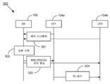
3 shows a method of obtaining a suitable component carrier for PC5 carrier aggregation in sidelink communication, in accordance with some embodiments of the present disclosure.
당업자가 본 발명을 만들고 사용할 수 있도록 본 발명의 다양한 예시적인 실시예가 첨부된 도면을 참조하여 아래에 설명되어 있다. 본 개시를 읽은 후 당업자에게 명백할 바와 같이, 본 발명의 범위를 벗어나지 않고 본 명세서에서 설명된 예에 대한 다양한 변경 또는 수정이 이루어질 수 있다. 따라서, 본 발명은 본 명세서에서 설명되거나 도시된 예시적인 실시예 및 응용으로 제한되지 않는다. 또한, 본 명세서에서 개시된 방법 내의 단계들의 특정한 순서 또는 체계는 단지 예시적인 접근일 뿐이다. 설계 선호도에 기반하여, 개시된 방법 또는 프로세스의 단계들의 특정한 순서 또는 체계는 본 발명의 범위 내에 머무르면서 재배열될 수 있다. 따라서, 당업자는 본 명세서에서 개시된 방법 및 기법이 다양한 단계 또는 동작을 샘플 순서로 나타내며, 본 발명은 명확히 달리 언급되지 않는 한 제시된 특정한 순서 또는 체계로 제한되지 않음을 이해할 것이다.Various exemplary embodiments of the present invention are described below with reference to the accompanying drawings so that those skilled in the art can make and use the present invention. As will be apparent to those skilled in the art after reading this disclosure, various changes or modifications can be made to the examples described herein without departing from the scope of the invention. Accordingly, the present invention is not limited to the exemplary embodiments and applications described or illustrated herein. Also, the specific order or scheme of steps within the method disclosed herein is merely an exemplary approach. Based on the design preferences, a particular order or scheme of steps of the disclosed method or process can be rearranged while remaining within the scope of the present invention. Accordingly, those skilled in the art will understand that the methods and techniques disclosed herein represent various steps or acts in a sample order, and that the present invention is not limited to the specific order or scheme presented, unless explicitly stated otherwise.
본 발명의 실시예가 첨부된 도면을 참조하여 상세히 설명된다. 동일하거나 유사한 컴포넌트는 비록 그들이 상이한 도면에 도시되어 있을지라도 동일하거나 유사한 참조번호로 표시될 수 있다. 당해 기술분야에서 잘 알려진 구성 또는 프로세스에 대한 상세한 설명은 본 발명의 청구 대상(subject matter)을 모호하게 하는 것을 피하기 위해 생략될 수 있다. 또한, 용어들은 본 발명의 실시예에서의 그들의 기능을 고려하여 정의되며, 사용자 또는 운용자의 의도, 용법 등에 따라 달라질 수 있다. 따라서, 정의는 본 명세서의 전체 내용을 기반으로 내려져야 할 것이다.Embodiments of the present invention will be described in detail with reference to the accompanying drawings. Identical or similar components may be labeled with the same or similar reference numerals, even if they are shown in different drawings. Detailed description of well-known configurations or processes in the art may be omitted to avoid obscuring the subject matter of the present invention. In addition, terms are defined in consideration of their functions in the embodiments of the present invention, and may be changed according to a user or operator's intention, usage, and the like. Therefore, the definition should be made based on the entire contents of this specification.
도 1a는 본 개시의 일부 실시예에 따라, 셀룰러 네트워크의 커버리지 안 및 밖에서의 사이드링크 통신을 도시하는 예시적인 무선 통신 네트워크(100)를 도시한다. 무선 통신 시스템에서, 네트워크 측 통신 노드 또는 기지국(BS)은 노드 B(node B), (진화된 노드 B(Evolved Node B, eNodeB 또는 eNB)로도 알려진) E-utran(evolved universal terrestrial radio access network) 노드 B, 피코 스테이션, 펨토 스테이션 또는 이와 유사한 것일 수 있다. 단말 측 노드 또는 사용자 장비(UE)는 이동 전화, 스마트폰, 개인 휴대 정보 단말기(PDA; Personal Digital Assitant), 태블릿, 랩탑 컴퓨터와 같은 장거리 통신 시스템 또는 예를 들어 웨어러블 디바이스, 차량 통신 시스템을 가진 차량 및 이와 유사한 것과 같은 단거리 통신 시스템일 수 있다. 네트워크 및 단말 측 통신 노드는 각각 BS(102) 및 UE(104)로 표현되며, 이들은 이하 본 개시의 모든 실시예에서 일반적으로 “통신 노드(communication nodes)”로 지칭된다. 이러한 통신 노드는 본 발명의 다양한 실시예에 따라, 무선 및/또는 유선 통신이 가능할 수 있다. 모든 실시예는 단지 선호되는 예이며, 본 개시를 제한하도록 의도되는 것이 아님에 주목하여야 한다. 따라서, 시스템은 본 개시의 범위 내에 머무르면서, UE 및 BS의 임의의 원하는 조합을 포함할 수 있음이 이해된다.1A shows an exemplary
도 1a를 참조하면, 무선 통신 네트워크(100)는 BS(102) 및 UE(104a), UE(104b) 및 UE(104c)를 포함한다. UE(104a)는 셀 내에서 움직이고 있는 것인 한편 제1 주파수 f1에서 동작하는 BS(102)와의 직접 통신 채널을 갖는 차량(V-UE) 또는 보행자(P-UE)일 수 있다. 유사하게, UE(104b)는 또한 동일한 셀 내에서 움직이고 있지만 BS(102)와의 직접 통신 채널(예를 들어, 103a)을 갖지 않을 수 있거나 셀(101)의 커버리지를 벗어난 것인 차량일 수 있다. 비록 UE(104b)가 BS(102)와의 직접 통신 채널을 갖지 않을지라도, 그것은 그것의 인접 UE, 예를 들어, 각각 제2 주파수 f2 및 제3 주파수 f3에서 동작하는 UE(104a) 및 UE(104c)와의 직접 통신 채널(예를 들어, 105a 및 105b)을 형성한다. 일부 실시예에서, 제2 주파수 f2 및 제3 주파수 f3는 제1 주파수 f1과 상이하다. 일부 실시예에서, 제2 주파수 f2 및 제3 주파수는 제1 주파수 f1과 동일하다. UE(104c)는 역시 제1 주파수 f1에서 동작하는 BS(102)와의 직접 통신 채널(103c)을 갖는 모바일 디바이스일 수 있다. 일부 실시예에서, 직접 통신 채널(예를 들어, 105a 및 105b)은 SL 통신을 위한 복수의 주파수에서 동작할 수 있다.Referring to FIG. 1A, the
UE(104) 및 BS(102) 간의 직접 통신 채널은 UMTS(Universal Mobile Telecommunication System) 무선 인터페이스로도 알려진 Uu 인터페이스와 같은 인터페이스를 통한 것일 수 있다. UE들 간의 직접 통신 채널(105)은 차량 간(V2V; Vehicle-to-Vehicle) 통신과 같은 높은 이동 속도 및 높은 밀도의 어플리케이션을 다루기 위해 도입된 PC5 인터페이스를 통한 것일 수 있다. BS(102)는 외부 인터페이스(107), 예를 들어, Iu 인터페이스를 통해 코어 네트워크(CN)(108)에 연결된다.The direct communication channel between the UE 104 and the BS 102 may be through an interface such as a Uu interface, also known as a Universal Mobile Telecommunication System (UMTS) air interface. The direct communication channel 105 between UEs may be through a PC5 interface introduced to handle high-speed and high-density applications such as vehicle-to-vehicle (V2V) communication. The
UE(104a 및 104c)는, 공공 시간 NTP(Network Time Protocol) 서버 또는 RNC(Radio Frequency Simulation System Network Controller) 서버와 같은 인터넷 시간 서비스를 통해 코어 네트워크(108)로부터 자신의 동기화 타이밍을 획득하는 BS(102)로부터, 자신의 동기화 타이밍을 획득한다. 이것은 네트워크 기반 동기화로 알려져 있다. 대안적으로, BS(102)는 또한, 특히 하늘로의 직선의 가시선(direct line of sight)를 갖는 대형 셀의 대형 BS를 위해, 위성 신호(106)를 통해 위성 항법 시스템(GNSS; Global Navigation Satellite System)(도시되지 않음)으로부터 동기화 타이밍을 획득할 수 있으며, 이는 위성 기반 동기화로 알려져 있다. UE(104b)는 사이드링크 통신을 통해 다른 UE들(104a 및 104c)로부터 자신의 동기화 타이밍을 획득한다.The
도 1b는 본 개시의 일부 실시예에 따라, 다운링크, 업링크 및 사이드링크 통신 신호를 송신 및 수신하기 위한 예시적인 무선 통신 시스템(150)의 블록 다이어그램을 도시한다. 시스템(150)은 본 명세서에서 상세히 설명될 필요가 없는 알려진 또는 종래의 동작 특징을 지원하도록 구성된 컴포넌트 및 구성요소를 포함할 수 있다. 하나의 예시적인 실시예에서, 시스템(150)은 상술한 바와 같이 도 1a의 무선 통신 네트워크(100)와 같은 무선 통신 환경에서 데이터 심볼을 송신 및 수신하는데 사용될 수 있다.1B shows a block diagram of an exemplary
시스템(150)은 일반적으로 BS(102) 및 논의의 용이성을 위해 아래에서 UE(104)로 통칭되는 두 개의 UE(104a 및 104b)를 포함한다. BS(102)는 BS 트랜시버 모듈(152), BS 안테나 어레이(154), BS 메모리 모듈(156), BS 프로세서 모듈(158) 및 네트워크 인터페이스(160)을 포함하며, 각각의 모듈은 데이터 통신 버스(180)를 통하여 필요에 따라 서로 결합되고(coupled) 상호 연결된다. UE(104)는 UE 트랜시버 모듈(162), UE 안테나(164), UE 메모리 모듈(166), UE 프로세서 모듈(168) 및 I/O 인터페이스(169)를 포함하며, 각각의 모듈은 데이터 통신 버스(190)를 통하여 필요에 따라 서로 결합되고 상호 연결된다. BS(102)는 본 명세서에서 설명된 바와 같은 데이터의 송신에 적합한 임의의 무선 채널 또는 당해 기술 분야에 알려진 다른 매체일 수 있는 통신 채널(192)을 통하여 UE(104)와 통신한다.
당업자에게 이해될 바와 같이, 시스템(150)은 도 1b에 도시된 모듈 이외의 임의의 수의 모듈을 더 포함할 수 있다. 당업자는 본 명세서에서 개시된 실시예와 관련하여 설명된 다양한 예시적인 블록, 모듈, 회로 및 프로세싱 로직이 하드웨어, 컴퓨터 판독가능 소프트웨어, 펌웨어 또는 이들의 임의의 실현 가능한 조합으로 구현될 수 있음을 이해할 것이다. 하드웨어, 펌웨어 및 소프트웨어의 이러한 상호교환성 및 호환성을 분명히 보여주기 위해, 다양한 예시적인 컴포넌트, 블록, 모듈, 회로 및 단계가 그들의 기능의 측면에서 일반적으로 설명된다. 이러한 기능이 하드웨어, 펌웨어 또는 소프트웨어로서 구현되는지 여부는 특정한 어플리케이션 및 전체 시스템에 부과된 설계 제약 조건에 달려 있다. 본 명세서에서 설명된 개념에 익숙한 사람들은 이러한 기능을 각각의 특정한 어플리케이션에 적합한 방식으로 구현할 수 있지만, 이러한 구현 결정은 본 발명의 범위를 제한하는 것으로서 해석되어서는 안 된다.As will be appreciated by those skilled in the art,
UE(140)의 송신 안테나로부터 BS(102)의 수신 안테나로의 무선 송신은 업링크 송신으로 알려져 있고, BS(102)의 송신 안테나로부터 UE(104)의 수신 안테나로의 무선 송신은 다운링크 송신으로 알려져 있다. 일부 실시예에 따라, UE 트랜시버(162)는 본 명세서에서 각각 UE 안테나(164)에 결합되는 RF 송신기 및 수신기 회로를 포함하는 “업링크(uplink)” 트랜시버(162)로 지칭될 수 있다. 이중 스위치(duplex switch)(도시되지 않음)는 대안적으로 업링크 송신기 또는 수신기를 업링크 안테나에 시간 이중통신(time duplex) 방식으로 결합할 수 있다. 유사하게, 일부 실시예에 따라, BS 트랜시버(152)는 본 명세서에서 각각 안테나 어레이(154)에 결합되는 RF 송신기 및 수신기 회로를 포함하는 “다운링크(downlink)” 트랜시버(152)로 지칭될 수 있다. 다운링크 이중 스위치는 대안적으로 다운링크 송신기 또는 수신기를 다운링크 안테나 어레이(154)에 시간 이중통신 방식으로 결합할 수 있다. 두 개의 트랜시버(152 및 162)의 동작은 다운링크 송신기가 다운링크 안테나 어레이(154)에 결합되는 것과 동시에 무선 통신 채널(192)을 통한 송신의 수신을 위해 업링크 수신기가 업링크 UE 안테나(164)에 결합되도록 시간적으로 조정된다. 바람직하게는, 이중 방향의 변화들 간의 최소의 가드 시간(guard time)만을 갖는 근접 동기화 타이밍이 존재한다. UE 트랜시버(162)는 UE 안테나(164)를 통해 BS(102)와 무선 통신 채널(192)을 통하여 통신하거나 다른 UE와 무선 통신 채널(193)을 통하여 통신한다. 무선 통신 채널(193)은 본 명세서에서 설명된 바와 같은 데이터의 사이드링크 송신에 적합한 임의의 무선 채널 또는 당해 기술 분야에 알려진 다른 매체일 수 있다.Wireless transmission from the transmit antenna of the UE 140 to the receive antenna of the
UE 트랜시버(162) 및 BS 트랜시버(152)는 무선 데이터 통신 채널(192)을 통하여 통신하도록 구성되고, 특정한 무선 통신 프로토콜 및 변조 방식을 지원할 수 있는 적합하게 구성된 RF 안테나 배열(154/164)과 협력한다. 일부 예시적인 실시예에서, UE 트랜시버(162) 및 BS 트랜시버(152)는 롱 텀 에볼루션(LTE; Long Term Evolution) 및 신흥 5G 표준 및 이와 유사한 것들과 같은 산업 표준을 지원하도록 구성된다. 그러나, 본 발명은 반드시 특정한 표준 및 관련 프로토콜에의 적용으로 제한되는 것은 아님이 이해될 것이다. 오히려, UE 트랜시버(162) 및 BS 트랜시버(152)는 미래의 표준 및 그 변형을 포함하는 대안적인 또는 추가적인 무선 데이터 통신 프로토콜을 지원하도록 구성될 수 있다.The
프로세서 모듈(158 및 168)은 본 명세서에서 설명된 기능을 수행하도록 설계된 범용 프로세서, 내용 주소화 메모리(content addressable memory), 디지털 신호 프로세서, 주문형 반도체(application specific integrated circuit), 필드 프로그램 가능 게이트 어레이, 임의의 적합한 프로그램 가능 로직 디바이스, 개별 게이트 또는 트랜지스터 로직, 개별 하드웨어 컴포넌트 또는 이들의 임의의 조합으로 구현되거나 실현될 수 있다. 이러한 방식으로, 프로세서는 마이크로프로세서, 컨트롤러, 마이크로컨트롤러, 상태 기계(state machine) 또는 이와 유사한 것으로서 실현될 수 있다. 프로세서는 또한 컴퓨팅 디바이스의 조합, 예를 들어 디지털 신호 프로세서 및 마이크로프로세서의 조합, 복수의 마이크로프로세서, 디지털 신호 프로세서 코어와 결합된 하나 이상의 마이크로프로세서 또는 임의의 다른 이러한 구성으로서 구현될 수 있다.
또한, 본 명세서에서 개시된 실시예와 관련하여 설명된 방법 또는 알고리즘의 단계들은 하드웨어로, 펌웨어로, 프로세서 모듈(158 및 168)에 의해 각각 실행되는 소프트웨어 모듈로 또는 이들의 임의의 실현 가능한 조합으로 직접 구현될 수 있다. 메모리 모듈(156 및 166)은 RAM 메모리, 플래시 메모리, ROM 메모리, EPROM 메모리, EEPROM 메모리, 레지스터, 하드디스크, 이동식 디스크, CD-ROM 또는 당해 기술 분야에 알려진 임의의 다른 형태의 저장 매체로서 실현될 수 있다. 이와 관련하여, 메모리 모듈(156 및 166)은 프로세서 모듈(158 및 168)이 각각 메모리 모듈(156 및 166)로부터 정보를 판독하고 메모리 모듈(156 및 166)에 정보를 기록할 수 있도록, 프로세서 모듈(158 및 168)에 각각 결합될 수 있다. 메모리 모듈(156 및 166)은 또한 그들의 각각의 프로세서 모듈(158 및 168)에 통합될 수 있다. 일부 실시예에서, 메모리 모듈(156 및 166)은 각각 프로세서 모듈(158 및 168)에 의해 각각 실행될 명령어의 실행 동안 임시 변수 또는 다른 중간 정보를 저장하기 위한 캐시 메모리를 포함할 수 있다. 메모리 모듈(156 및 166)은 또한 각각 프로세서 모듈(158 및 168)에 의해 각각 실행될 명령어를 저장하기 위한 비휘발성 메모리를 포함할 수 있다.In addition, the steps of the method or algorithm described in connection with the embodiments disclosed herein may be directly in hardware, in firmware, in software modules executed by
네트워크 인터페이스(160)는 일반적으로 BS 트랜시버(152)와 BS(102)와 통신하도록 구성된 다른 네트워크 컴포넌트 및 통신 노드 간의 양방향 통신을 가능하게 하는 기지국(102)의 하드웨어, 소프트웨어, 펌웨어, 프로세싱 로직 및/또는 다른 컴포넌트를 나타낸다. 예를 들어, 네트워크 인터페이스(160)는 인터넷 또는 WiMAX 트래픽을 지원하도록 구성될 수 있다. 전형적인 배치에서, 제한 없이, 네트워크 인터페이스(160)는 BS 트랜시버(152)가 종래의 이더넷(Ethernet) 기반 컴퓨터 네트워크와 통신할 수 있도록 802.3 이더넷 인터페이스를 제공한다. 이러한 방식으로, 네트워크 인터페이스(160)는 컴퓨터 네트워크(예를 들어, 이동 교환국(MSC; Mobile Switching Center))로의 연결을 위한 물리적 인터페이스를 포함할 수 있다. 특정한 동작 또는 기능과 관련하여 본 명세서에서 사용되는 “~을 위해 구성되는(configured for)” 또는 “~하도록 구성되는(configured to)”이라는 용어는 특정한 동작 또는 기능을 수행하도록 물리적으로 구성, 프로그래밍, 포맷화 및/또는 배치되는 디바이스, 컴포넌트, 회로, 구조, 기계, 신호 등을 지칭한다. 네트워크 인터페이스(160)는 BS(102)가 유선 또는 무선 연결을 통해 다른 BS 또는 코어 네트워크와 통신하게 할 수 있다.The
다시 도 1a를 참조하면, 상술한 바와 같이, BS(102)는 UE(104)가 BS(102)가 위치한 셀(101) 내의 네트워크에 액세스하고, 일반적으로, 셀(101) 내에서 적절히 작동하게 할 수 있도록 BS(102)와 관련된 시스템 정보를 하나 이상의 UE(예를 들어, 104)에 반복적으로 브로드캐스트(broadcast)한다. 예를 들어, 다운링크 및 업링크 셀 대역폭, 다운링크 및 업링크 구성, 랜덤 액세스를 위한 구성 등과 같은 복수의 정보가 시스템 정보에 포함될 수 있으며, 이는 아래에서 더 상세히 논의될 것이다. 전형적으로, BS(102)는 몇몇 주요 시스템 정보, 예를 들어, 셀(101)의 구성을 전달하는 제1 신호를 PBCH(Physical Broadcast Channel, 물리적 브로드캐스트 채널)를 통해 브로드캐스트한다. 예시의 명확성을 위하여, 이러한 브로드캐스트된 제1 신호는 본 명세서에서 “제1 브로드캐스트 신호(first broadcast signal)”로 지칭된다. BS(102)는 그 뒤에 몇몇 다른 시스템 정보를 전달하는 하나 이상의 신호를 각각의 채널(예를 들어, 물리적 다운링크 공유 채널(PDSCH; Physical Downlink Shared Channel))을 통해 브로드캐스트할 수 있음에 주목하여야 하며, 이는 본 명세서에서 “제2 브로드캐스트 신호”, “제3 브로드캐스트 신호” 등으로 지칭된다.Referring again to FIG. 1A, as described above,
다시 도 1b를 참조하면, 일부 실시예에서, 제1 브로드캐스트 신호에 의해 전달되는 주요 시스템 정보는 BS(102)에 의해 심볼 포맷으로 통신 채널(192)(예를 들어, PBCH)을 통하여 송신될 수 있다. 일부 실시예에 따라, 주요 시스템 정보의 원래의 형태는 하나 이상의 디지털 비트의 시퀀스로 나타내어질 수 있고 하나 이상의 디지털 비트의 시퀀스는, 제1 브로드캐스트 신호가 되기 위해, 그 전부가 BS 프로세서 모듈(158)에 의해 프로세싱될 수 있는 복수의 단계(예를 들어, 코딩, 스크램블링, 변조(modulation), 매핑 단계 등)를 거쳐 프로세싱될 수 있다. 유사하게, UE(104)가 UE 트랜시버(162)를 사용하여 제1 브로드캐스트 신호를 (심볼 포맷으로) 수신할 때, 일부 실시예에 따라, UE 프로세서 모듈(168)은 예를 들어, 주요 시스템 정보의 비트의 비트 위치, 비트 번호 등과 같은 주요 시스템 정보를 추정하기 위해 복수의 단계(디매핑(de-mapping), 복조(demodulation), 디코딩 단계 등)를 수행할 수 있다. UE 프로세서 모듈(168)은 또한 I/O 인터페이스(169)에 결합되며, 이는 UE(104)에 컴퓨터와 같은 다른 디바이스에 연결하는 능력을 제공한다. I/O 인터페이스(169)는 이들 액세서리와 UE 프로세서 모듈(168) 간의 통신 경로이다.Referring again to FIG. 1B, in some embodiments, key system information carried by the first broadcast signal is to be transmitted over the communication channel 192 (eg, PBCH) in symbol format by the
일부 실시예에서, UE(104)는 UE가 BS(102)와 그리고 다른 UE, 예를 들어 104a와 104b 간과 통신하는 하이브리드 통신 네트워크에서 동작할 수 있다. 아래에서 더 상세히 설명되는 바와 같이, UE(104)는 BS(102)와 UE(104) 간의 다운링크/업링크 통신뿐만 아니라 다른 UE와의 사이드링크 통신 또한 지원한다. 위에서 논의된 바와 같이, 사이드링크 통신은, BS(102)가 UE들 간에서 데이터를 중계하도록 요구하는 것 없이 UE(104a 및 104b)가 서로와의, 또는 상이한 셀로부터의 다른 UE와의 직접 통신 링크를 구축할 수 있게 한다.In some embodiments, UE 104 may operate in a hybrid communication network in which the UE communicates with
도 2는 본 개시의 일부 실시예에 따라, SL 통신을 위한 PC5 캐리어 어그리게이션(CA)에서 적어도 하나의 적합한 컴포넌트 캐리어(CC; Component Carrier)를 획득하는 방법(200)을 도시한다. 도 2의 방법(200) 이전, 도중 및 이후에 추가적인 동작이 제공될 수 있으며, 일부 다른 동작은 본 명세서에서 생략되거나 간략하게만 설명될 수 있음이 이해된다.2 shows a
방법(200)은 BS(102)가 UE1(104a) 및 UE2(104b)에 메시지를 송신하는 동작(201)으로 시작한다. 메시지는 SL 통신을 위한 PC5-CA에서 적어도 하나의 적합한 캐리어 주파수 또는 적어도 두 개의 적합한 CC의 결정에 사용되는 정보를 포함한다. 일부 실시예에서, 이 메시지는 제어 시그널링, 예를 들어 물리 계층 위의 계층으로부터의 RRC(Radio Resource Control) 메시지 또는 시스템 메시지의 형태로 BS(102)로부터 UE1(104a) 및 UE2(104b)로 송신된다. 이 메시지는 PBCH(Physical Broadcast Channel) 또는 PDSCH(Physical Downlink Shared Channel) 및 이와 유사한 것과 같은 채널에서 브로드캐스트 및/또는 유니캐스트(unicast)될 수 있다.
일부 실시예에서, BS(102)로부터 UE1(104a) 및 UE(104b)로의 메시지로 송신된 정보는 다음의 정보 중 적어도 하나를 포함한다: 적어도 하나의 채널 사용률(CBR; Channel Busy Ratio) 임계값(threshold value), 적어도 하나의 PC5 링크 품질 임계값, 서비스 타입/서비스 품질(QoS; Quality of Service) 요구사항과 요구되는 CC의 수 간의 매핑 관계 및 서비스 타입/QoS 요구사항과 주파수 아이덴티티 간의 매핑 관계.In some embodiments, the information transmitted in the message from
일부 실시예에서, BS(102)로부터 UE1(104a) 및 UE2(104b)로의 메시지로 송신된 정보는 적어도 하나의 CBR 임계값을 포함한다. CBR 값은 0과 1 사이의 값으로, 사용률을 수신된 신호의 전력(수신된 신호 강도 표시기(received signal strength indicator, 또는 SRSSI)이 전력 임계값(예를 들어, -85 dBm)보다 큰 서브 채널의 일부로서 나타낸다. 일부 실시예에서, 정보는 복수의 CBR 임계값을 포함하고, 복수의 CBR 임계값들의 각각은 서비스 타입 및/또는 QoS 요구사항과 연관된다. QoS 요구사항은 다음의 파라미터 중 적어도 하나를 나타낸다: 데이터 우선순위, 패킷 지연 규격(packet delay budget), 패킷 에러율, 데이터율 및 송신될 데이터 패킷의 신뢰성. 일부 실시예에서, QoS 요구사항은 인덱스 값일 수 있고 CBR 임계값과 매핑 관계를 가질 수 있다. 예를 들어, 높은 데이터율에서의 SL 통신을 위해 이용 가능한 더 많은 적합한 CC가 존재하도록, 높은 우선순위 및 높은 데이터율을 갖는 서비스 데이터 송신에 대응하는 CBR 임계값은 낮은 우선순위 및 낮은 데이터율을 갖는 서비스 데이터 송신에 대응하는 CBR 임계값보다 더 클 수 있다.In some embodiments, the information sent in the message from
일부 실시예에서, BS(102)로부터 UE1(104a) 및 UE2(104b)로의 메시지로 송신된 정보는 적어도 하나의 PC5 링크 품질 임계값을 포함하고, PC5 품질 임계값은 예를 들어 기준 신호 수신 전력(RSRP; Reference Signal Received Power), 기준 신호 수신 품질(RSRQ; Reference Signal Received Quality), 신호 대 간섭 잡음비(SINR; Signal to Interference plus Noise Ratio) 및 이와 유사한 것과 같은 파라미터에 의해 기술된다. 일부 실시예에서, 정보는 복수의 PC5 품질 임계값을 포함하고, 복수의 PC5 품질 임계값들의 각각은 서비스 타입 및/또는 QoS 요구사항과 연관된다. QoS 요구사항은 다음의 파라미터 중 적어도 하나를 나타낸다: 데이터 우선순위, 패킷 지연 규격, 패킷 에러율, 데이터율, 송신될 데이터 패킷의 신뢰성. 일부 실시예에서, QoS 요구사항은 인덱스 값일 수 있고 PC5 품질 임계값과 매핑 관계를 가질 수 있다. 예를 들어, 높은 데이터율에서의 SL 통신을 위해 이용 가능한 더 많은 적합한 CC가 존재하도록, 높은 우선순위 및/또는 높은 데이터율을 갖는 서비스 데이터 송신에 대응하는 PC5 품질 임계값은 낮은 우선순위 및/또는 낮은 데이터율을 갖는 서비스 데이터 송신에 대응하는 PC5 품질 임계값보다 더 낮을 수 있다.In some embodiments, information transmitted in a message from
일부 실시예에서, BS(102)로부터 UE1(104a) 및 UE2(104b)로의 메시지로 송신된 정보는 서비스 타입/QoS 요구사항과 요구되는 CC의 수 간의 매핑 관계를 포함한다. QoS 요구사항은 다음의 파라미터 중 적어도 하나를 나타낸다: 데이터 우선순의, 패킷 지연 규격, 패킷 에러율, 데이터율 및 송신될 데이터 패킷의 신뢰성. 일부 실시예에서, QoS 요구사항은 인덱스 값일 수 있다.In some embodiments, the information sent in a message from
일부 실시예에서, BS(102)로부터 UE1(104a) 및 UE(104b)로의 메시지로 송신된 정보는 서비스 타입/QoS 요구사항과 주파수 아이덴티티 간의 매핑 관계를 포함한다. QoS 요구사항은 다음의 파라미터 중 적어도 하나를 나타낸다: 데이터 우선순위, 패킷 지연 규격, 패킷 에러율, 데이터율, 전송될 데이터 패킷의 신뢰성. 일부 실시예에서, QoS 요구사항은 인덱스 값일 수 있다. 일부 실시예에서, 주파수 아이덴티티는 다음의 파라미터 중 적어도 하나를 포함한다: 주파수 값, 주파수 인덱스 및 CC 인덱스.In some embodiments, the information sent in the message from
일부 실시예에서, BS(102)로부터 UE1(104a) 및 UE2(104b)로의 메시지로 송신된 정보는 SL 송신을 위한 시간 도메인의 자원 정보를 포함하고, 시간 도메인의 자원 정보는 서브프레임 패턴 정보의 리스트 및 대응하는 주파수(인덱스)일 수 있다.In some embodiments, the information sent in the message from
일부 실시예에서, BS(102)로부터 UE1(104a) 및 UE2(104b)로의 메시지로 송신된 정보는 BS(102) 및/또는 SL 송신에 사용될 수 있는 주파수에 의해 지원되는 이용 가능한 캐리어 주파수의 리스트를 포함한다.In some embodiments, the information sent in the message from
대안적으로, 방법(200)은 동작(202)으로 시작할 수 있고, 여기서 UE2(104a)는 PSSCH(Physical Sidelink Shared Channel, 물리적 사이드링크 공유 채널) 또는 이와 유사한 것과 같은 채널 상에서 송신될 수 있는 PC5 시그널링을 통해 다른 UE(예를 들어, UE2(104b))로부터 CC 선택에 사용되는 정보를 획득할 수 있다. 일부 실시예에서, UE2(104b)로부터 UE1(104a)으로 송신된 정보는 다음의 파라미터 값 중 적어도 하나를 포함한다: PC5-CA를 위한 UE2(104b)의 능력(capability), CC의 수, 송신/수신에 사용될 수 있는 캐리어 주파수 및 수신 체인(receiving chain)의 수. 일부 실시예에서, PC5-CA를 위한 UE(104b)의 능력은 다음 중 적어도 하나를 포함한다: 동시 SL 수신을 위한 대역 결합, 동시 Uu/사이드링크 수신을 위한 대역 결합.Alternatively,
일부 실시예에서, UE1(104a)는 또한 BS(102) 및 UE2(104b) 모두로부터 동시에 정보를 수신할 수 있다. 이 경우, 만약 두 종류의 정보가 서로 충돌한다면 SL 송신을 위한 PC5-CA의 적합한 CC의 선택을 위하여 BS(102)로부터 수신된 정보가 UE2(104b)로부터 수신된 정보보다 더 높은 사용 우선순위를 갖는다.In some embodiments,
방법(200)은 동작(203)으로 이어지며, 여기서 UE1(104a)은 동작(201)에서 BS(102)로부터 수신된 정보 및/또는 동작(202)에서 UE(104b)로부터 수신된 정보에 기반하여 PC5-CA를 위한 적어도 하나의 적합한 CC를 선택한다. 일부 실시예에서, UE(104a)의 상위 계층은 데이터 패킷의 서비스 타입 또는 QoS 요구사항 및 서비스 타입/QoS와 주파수 간의 매핑 관계에 따라 후보 캐리어의 세트를 결정한다. 일부 실시예에서, UE(104a)의 상위 계층은 또한 요구되는 CC의 수를 결정할 수 있다. 그 후 상위 계층은 후보 주파수의 세트를 UE(104a)의 하위 계층(액세스 층(Access Stratum) 또는 AS 계층)으로 전달한다. 일부 실시예에서, 상위 계층은 또한 요구되는 CC의 수를 AS 계층으로 전달한다. UE1(104a)의 AS 계층은 다음의 파라미터 중 적어도 하나에 따라 송신 주파수를 결정한다: 측정된 CBR 값, 측정된 PC5 링크 품질 값, 후보 주파수 및 PC5-CA를 위한 UE1(104a)의 능력.
일부 실시예에서 UE1(104a)는 서브채널에서 수신된 전력을 측정함으로써 주파수(또는 자원 풀)의 CBR 값을 결정하고 전체 자원 풀에서 사용 중인 서브채널의 비율을 계산한다. 일부 실시예에서, UE1(104a)는 UE2(104b)로부터 PSSCH(Physical Sidelink Shared Channel, 물리적 사이드링크 공유 채널) 및 이와 유사한 것과 같은 채널 상에서 송신된 기준 신호(RS)를 측정함으로써 PC5 링크 품질을 결정한다.In some embodiments,
일부 실시예에서, 측정된 CBR 값은 적어도 하나의 구성된(configured) CBR 임계값과 비교된다. 선호되는 실시예에서, 오직 하나의 CBR 임계값이 동작(201)동안 BS(102)로부터 UE(104)로 송신된다. 만약 주파수의 측정된 CBR 값이 구성된 CBR 임계값보다 작다면, 주파수는 SL 송신을 위한 PC5-CA의 적합한 CC가 될 수 있다. 만약 주파수의 측정된 CBR 값이 구성된 CBR 임계값보다 크다면, 주파수는 SL 송신을 위한 PC5-CA의 CC로서의 사용에 적합하지 않은 것으로 간주된다. 일부 실시예에서, 두 개의 구성된 CBR 임계값(예를 들어, CBR1 < CBR2)은 동작(201)동안 BS(102)로부터 UE(104)로 송신된다. 만약 주파수의 측정된 CBR 값이 CBR1보다 작다면, 주파수는 SL 송신을 위한 PC5-CA의 적합한 CC로서 선택된다. 만약 주파수의 측정된 CBR 값이 CBR1보다 크다면, 주파수는 SL 송신에 적합하지 않은 것으로서 간주된다. 특정 실시예에서, 두 개의 구성된 CBR 임계값 중 하나(예를 들어, CBR2)는, 아래에서 상세히 논의되는 바와 같이, CC가 SL 송신을 계속하기에 적합하지 않게 되는 지의 여부를 결정하는데 사용될 수 있는 한편, CBR1은 주파수가 SL 송신에 적합한 지의 여부를 결정하는 데 사용된다.In some embodiments, the measured CBR value is compared to at least one configured CBR threshold. In the preferred embodiment, only one CBR threshold is transmitted from
일부 실시예에서, 측정된 PC5 링크 품질 값은 적어도 하나의 구성된 PC5 링크 품질 임계값과 비교된다. 선호되는 실시예에서, 오직 하나의 구성된 PC5 링크 품질 임계값만이 동작(201) 동안 BS(102)로부터 UE(104)로 송신된다. 만약 주파수의 측정된 PC5 링크 품질 값이 구성된 PC5 링크 품질 임계값보다 크다면, 주파수는 SL 송신을 위한 PC5-CA의 적합한 CC이다. 만약 주파수의 측정된 PC5 링크 품질 값이 미리 구성된(pre-configured) PC5 링크 품질 임계값보다 작다면, 주파수는 SL 송신에 적합하지 않은 것으로 간주된다. 일부 실시예에서, 두 개의 구성된 PC5 링크 품질 임계값(예를 들어, SPC52 < SPC51)이 동작(201) 동안 BS(102)로부터 UE(104)로 송신된다. 만약 주파수의 측정된 PC5 링크 품질 값이 SPC51보다 크다면, 주파수는 SL 송신을 위한 PC5-CA의 적합한 CC로서 간주된다. 만약 주파수의 측정된 PC5 링크 품질 값이 SPC52보다 작다면, 주파수는 SL 송신에 적합하지 않은 것으로 간주된다. 일부 실시예에서, 두 개의 구성된 PC5 링크 품질 임계값은 아래에서 상세히 논의되는 바와 같이 빈번한 CC 재선택을 피하기 위해 사용될 수 있다.In some embodiments, the measured PC5 link quality value is compared to at least one configured PC5 link quality threshold. In the preferred embodiment, only one configured PC5 link quality threshold is transmitted from
대안적인 실시예에서, 동작(203) 동안 UE1(104a)의 상위 계층은 데이터 패킷, 서비스 타입, QoS 요구사항 및 서비스 타입과 주파수 간의 매핑 관계를 UE1(104a)의 하위 계층(AS 계층)으로 전달할 수 있다. 그 후 UE1(104a)의 AS 계층은 다음의 파라미터 중 적어도 하나에 따라 SL 송신을 위한 PC5-CA에서 사용될 수 있는 주파수를 결정한다: 연관된 서비스 타입, 연관된 QoS 요구사항, 서비스 타입과 주파수 간의 매핑, UE1(104a)의 능력, PC5-CA를 위한 UE2(104b)의 능력, 측정된 CBR 값 및 측정된 PC5 링크 품질 값.In an alternative embodiment, during
또다른 대안적인 실시예에서, 동작(203) 동안 CC는 비 AS 계층(non-AS layer)(예를 들어, 상위 계층)에 의해 선택될 수 있다. 예를 들어, UE(104a)의 상위 계층은 데이터 패킷의 서비스 타입 또는 QoS 요구사항 및 서비스 타입/QoS와 주파수 간의 매핑 관계에 따라 후보 캐리어의 세트를 결정한다. 일부 실시예에서, UE(104a)의 상위 계층은 또한 요구되는 CC의 수를 결정할 수 있다. 그 후 상위 계층은 후보 주파수의 세트를 UE(104a)의 AS 계층으로 전달한다. 일부 실시예에서, 상위 계층은 또한 요구되는 CC의 수를 AS 계층으로 전달한다. 그 후 AS 계층은 다음의 파라미터 중 하나를 UE(104a)의 상위 계층으로 다시 전달할 수 있다: 측정된 CBR 값, 측정된 PC5 링크 품질 값, 서비스 타입, 연관된 QoS 요구사항, 서비스 타입과 주파수 간의 매핑 관계, UE1(104a)의 능력, PC5-CA를 위한 UE2(104b)의 능력, CBR 값이 구성된 임계값보다 낮은 주파수, PC5 링크 품질 값이 구성된 임계값보다 높은 주파수. 마지막으로, 상위 계층은 SL 송신에 사용될 수 있는 적어도 하나의 적합한 CC를 결정하는 한편, UE1(104a)의 하위 계층에게 표시한다.In another alternative embodiment, the CC during
동작(203)에서 CC를 선택한 후, UE1(104a)는 SL 송신을 위한 시간-주파수 도메인에서 자원을 선택한다. 일부 실시예에서, BS(102)로부터 수신된 서브프레임 패턴은 “0” 또는 “1”의 스트링을 포함하고, 여기서 “0”은 이 주파수 상의 이 서브프레임이 SL 송신에 사용될 수 없음을 나타내고 “1”은 이 주파수 상의 이 서브프레임이 SL 송신에 사용될 수 있음을 나타낸다. UE는 모든 후보 자원의 감지에 기반하여 SL 송신을 위한 서브프레임에서 자원 블록을 더 선택할 수 있다.After selecting the CC in
방법(20)은 UE1(104a)과 UE2(104b) 간에 데이터를 송신 또는 수신하기 위한 자원이 선택될 때 SL 송신을 위한 동작(204)으로 이어진다. 자원이 선택된 후, 최대 여덟 개의 CC가 더 높은 피크 데이터율을 실현하고 단편화된 스펙트럼의 효율적인 사용을 가능하게 하기 위해 SL 송신을 위한 제1 집합(aggregated) CC를 형성하도록 할당될 수 있다. 일부 실시예에서, UE가 차량일 때, SL 송신에서의 집합 CC를 통한 데이터는 예를 들어 사고와 같은 무작위의 사건에 의해 촉발될(triggered) 수 있는 브레이크/가속 정보 및 경로 옵션을 포함할 수 있다. 일부 실시예에서, V-UE인 UE(104)는 노변 장치(RSU; RoadSide Unit)로부터 환경 및 교통 정보를 획득할 수 있고 다른 UE에게 주기적으로 브로드캐스트할 수 있다. 한편, UE(104)는 다른 UE로부터 상태 보고를 수집하고 RSU로 다시 송신할 수 있으며, 이 또한 SL 송신의 예가 될 수 있다.Method 20 continues with
SL 송신이 제1 집합 CC에서 구축된 후, 제1 집합 CC 내의 적어도 하나의 CC의 적합성은 SL 송신 동안 미리 정의된 주기로 계속적으로 모니터링되고 주기적으로 평가된다. 이 프로세스는 SL 통신을 위한 높은 데이터율 및 낮은 지연을 갖는 안정적인 CC를 강화하고 유지하기 위해 구현될 수 있다. 일부 실시예에서, 제1 집합 CC의 적합성은 다음의 파라미터 중 적어도 하나에 의해 측정된다: 측정된 CBR 값 및 측정된 PC5 링크 품질 값. 만약 제1 집합 CC(예를 들어, 주파수)가 SL 송신에 적합하지 않게 된다면, CC 재선택 절차는 기존의 SL 송신을 계속하기 위해 제2 집합 CC를 형성하도록 적합한 CC를 재선택하기 위해 UE(104)에 의해 촉발될 수 있다. 일부 실시예에서, 송신 UE2(104b)는 CC의 재선택을 촉발할 수 있다. 예를 들어, 만약 제1 집합 CC의 적어도 하나의 CBR 값이 구성된 임계값보다 커지게 되면, 제2 집합 CC가 선택되어야 한다. 일부 실시예에서, 구성된 임계값보다 낮은 CBR 값을 갖는 주파수는 SL 송신을 위한 PC5-CA의 적합한 CC가 될 수 있다. 일부 실시예에서, 구성된 CBR 오프셋 값만큼 제1 집합 CC 내 주파수의 CBR 값보다 낮은 CBR 값을 갖는 주파수는 SL 송신을 위한 PC5-CA의 제2 집합 CC에서 적합한 CC로서 사용될 수 있다. 일부 실시예에서, CC 재선택을 위한 구성된 CBR 오프셋 값은 BS(102)에 의해 동작(201)에서 브로드캐스트 또는 유니캐스트(즉, 전용 시그널링)를 통하여 구성될 수 있다. 특정 실시예에서, UE2(104b)는 수신된 전력에 기반하여 제1 집합 CC의 각 CC의 CBR 값을 측정하고 전체 자원 풀에서 사용 중인 서브채널의 비율을 계산한다.After the SL transmission is established in the first set CC, the suitability of at least one CC in the first set CC is continuously monitored and periodically evaluated at a predefined period during SL transmission. This process can be implemented to enhance and maintain a stable CC with high data rate and low delay for SL communication. In some embodiments, the suitability of the first set CC is measured by at least one of the following parameters: measured CBR value and measured PC5 link quality value. If the first set CC (e.g., frequency) becomes unsuitable for SL transmission, the CC reselection procedure allows the UE to reselect a suitable CC to form a second set CC to continue the existing SL transmission ( 104). In some embodiments, transmitting
유사하게, PC5 링크 품질은 제1 집합 CC의 적합성을 측정하는 데 사용될 수 있다. 특히, 제1 집합 CC 내 모든 CC의 PC5 링크 품질 값은 끊임없이 모니터링되고 평가된다. 만약 제1 집합 CC의 주파수의 측정된 PC5 링크 품질 값이 동작(201)에서 BS(102)에 의해 UE(104)로 송신되는 구성된 PC5 링크 품질 임계값보다 낮은 값으로 감소하면, SL 송신을 계속하기 위해 제2 집합 CC가 재선택되어야 한다. PC5 링크 품질은 UE2(104b)로부터 송신된 기준 신호(RS)의 측정을 통해 평가된다. 일부 실시예에서, 만약 주파수의 PC5 링크 품질 값이 구성된 임계값보다 더 크면, 주파수는 SL 송신을 위한 PC5-CA의 적합한 CC가 된다. 일부 실시예에서, 구성된 PC5 링크 품질 오프셋 값만큼 제1 집합 CC 내 주파수의 PC5 링크 품질 값보다 큰 주파수의 PC5 링크 품질 값 또한 적합한 CC로서 사용될 수 있다. 제1 집합 CC의 적합한 CC와 함께, 새롭게 선택된 적합한 CC는 SL 송신을 위한 제2 집합 CC를 형성하는 데 사용될 수 있다. 일부 실시예에서, CC 재선택을 위한 구성된 PC5 링크 품질 오프셋 값은 BS(102)에 의해 동작(201)에서 브로드캐스트 또는 유지캐스트(즉, 전용 시그널링)를 통하여 구성될 수 있다. 일부 실시예에서, PC5 링크 품질 값에 기반한 CC의 재선택은 유니캐스트 시나리오에서만 적용 가능하다.Similarly, PC5 link quality can be used to measure the suitability of the first set CC. In particular, the PC5 link quality values of all CCs in the first set CC are constantly monitored and evaluated. If the measured PC5 link quality value of the frequency of the first set CC decreases to a value lower than the configured PC5 link quality threshold transmitted from the
다양한 실시예에 따라, SL 송신을 계속하기에 적합하지 않은 것으로 결정될 때까지 CC 상에서 송신되지 않은 데이터 패킷은 계속적인 송신을 위해 제2 집합 CC의 새롭게 선택된 적합한 CC로 전환된다. 동시에, 제1 집합 CC 내 다른 모든 적합한 주파수 상의 데이터 패킷은 계속적으로 송신되고 CC 재선택 프로세스 동안 SL 송신에 대한 중단이 가해지지 않는다.According to various embodiments, data packets not transmitted on the CC are switched to the newly selected suitable CC of the second set CC for continuous transmission until it is determined that it is not suitable for continuing the SL transmission. At the same time, data packets on all other suitable frequencies in the first set CC are continuously transmitted and there is no interruption to SL transmission during the CC reselection process.
도 3은 본 개시의 다양한 실시예에 따라, SL 송신을 위한 PC5-CA의 적어도 하나의 적절한 컴포넌트 캐리어를 획득하는 방법(300)을 도시한다. 도 3의 방법(300) 이전, 도중 및 이후에 추가적인 동작이 제공될 수 있으며, 일부 다른 동작은 본 명세서에서 생략되거나 간략하게만 설명될 수 있음이 이해된다.3 shows a
방법(300)은 송신 UE1(104a)이 BS(102)로 메시지를 송신하는 동작(301)으로 시작한다. 일부 실시예에서, 수신 UE2(104b) 또한 만약 그것이 유니캐스트 통신을 수행하고 있다면 동작(301) 동안 BS(102)로 메시지를 송신할 수 있다. 메시지는 다양한 실시예에 따라, 예를 들어 언제 새로운 SL 송신이 송신 및 수신 UE 간에 구축되어야 하는 지와 같은 CC 선택을 위한 보조 정보를 포함한다. 일부 실시예에서, UE로부터 BS로의 CC 선택을 위한 보조 정보의 송신은 또한 UE가 하나 이상의 타입의 서비스를 송신 또는 수신하는 데 관심이 있을 때 촉발될 수 있다. UE(104)로부터의 메시지는 업링크 제어 시그널링 메시지(예를 들어, RRC(Radio Resource Control, 무선 자원 제어) 메시지 또는 MAC 계층의 제어 구성요소(CE; Control Element)의 형태로 BS(102)로 송신될 수 있다. UE(104)로부터 BS(102)로 송신되는 CC 선택을 위한 보조 정보는 다음의 파라미터 중 적어도 하나를 포함한다: 로직 채널 그룹(LCG; Logical Channel Group) ID, 서비스 타입, QoS 요구사항, 무선 베어러(bearer) 아이덴티티/로직 채널 ID 및 PC5-CA를 위한 UE의 능력, 하나 이상의 주파수 정보. 특정 실시예에서, UE(104)로부터 BS(102)로의 LCG ID는 송신 UE1(104a)로부터 수신 UE2(104b)로 송신되어야 하는 데이터 패킷의 서비스 타입 및/또는 QoS 요구사항을 암시적으로 나타낼 수 있다. UE가 BS(102)로 LCGID를 송신하기 전에, UE는 특정 실시예에 따라, BS(102)로부터 LCGID와 서비스 타입 및/또는 QoS 요구사항 간의 매핑 관계를 얻을 수 있다. 일부 실시예에서, LCGID와 서비스 타입 및/또는 QoS 요구사항 간의 매핑 관계는 미리 구성될 수 있다. 일부 실시예에서, 이 매핑 관계는 어플리케이션 서비스로부터 획득될 수 있다. QoS 요구사항은 다음의 파라미터 중 적어도 하나를 포함한다: 데이터 우선순위, 데이터 패킷 지연 규격, 데이터율, 패킷 에러율 및 QoS 인덱스. 일부 실시예에서, QoS 인덱스는 BS(102)에 의해 할당될 수 있다. 특정 실시예에서, 무선 베어러 아이덴티티 또는 로직 채널 ID는 서비스 타입 및/또는 QoS 요구사항을 암시적으로 나타내는 데 사용될 수 있다. UE가 무선 베어러 아이덴티티 또는 로직 채널 ID를 BS(102)로 송신하기 전에, UE는 특정 실시예에 따라, BS(102)로부터 무선 베어러 아이덴티티와 서비스 타입 및/또는 QoS 요구사항 간의 매핑 관계 또는 로직 채널 ID와 서비스 타입 및/또는 QoS 요구사항 간의 매핑 관계를 얻을 수 있다. 일부 실시예에서, 위에서 언급된 매핑 관계는 미리 구성될 수 있다. 일부 실시예에서, 이 매핑 관계는 어플리케이션 서비스로부터 획득될 수 있다. 방법(200)과 유사하게, PC5-CA를 위한 UE의 능력은 특정 실시예에 따라 적어도 동시 SL 송신을 위한 대역 결합, 동시 Uu/사이드링크 송신을 위한 대역 결합, 동시 SL 수신을 위한 대역 결합, 동시 Uu/사이드링크 수신을 위한 대역 결합을 포함한다. 일부 실시예에서, 주파수 정보는 UE가 사이드링크 자원을 요청하는 주파수를 표시한다.The
방법(300)은 BS(102)가 SL 송신에 사용될 수 있는 적합한 주파수를 결정하는 동작(302)으로 이어진다. 특정 실시예에서, BS(102)는 UE(104)로부터의 요청 메시지에서 수신된 정보에 기반하여 SL 송신을 위한 자원 정보를 결정한다.
방법(300)은 BS(102)가 시간-주파수 자원을 송신 및 수신 UE에 제어 시그널링, 예를 들어 RRC 메시지 또는 PDCCH 제어 정보 또는 시스템 메시지의 형태로 할당하는 동작(303)으로 이어진다. 일부 실시예에서, BS(102)는 OAM 구성을 통하여 서비스 타입과 주파수 간의 매핑 관계를 획득한다. SL 송신을 위한 자원 정보는 다음의 파라미터 중 적어도 하나를 포함한다: SL 송신을 위한 시간-주파수 도메인에서의 자원 정보, PC5-CA에서 사용될 수 있는 적합한 주파수, 자원 및 대응하는 주파수의 시간 도메인 정보(즉, 서브 프레임 패턴) 및 요구되는 CC의 수. 특정 실시예에서, 시간 도메인에서의 자원 정보는 서비스 타입 및/또는 주파수와 연관된다.
방법(300)은 송신 UE1(104a)과 수신 UE2(104b) 간에서 데이터를 송신 또는 수신하기 위한 자원이 BS(102)로부터 수신될 때 SL 송신을 위한 동작(304)으로 이어진다. 일부 실시예에서, UE가 차량일 때, SL 송신에서의 데이터는 예를 들어 사고와 같은 무작위의 사건에 의해 촉발될 수 있는 브레이크/가속 정보 및 경로 옵션을 포함할 수 있다. 일부 실시예에서, V-UE인 UE(104)는 노변 장치(RSU; RoadSide Unit)로부터 환경 및 교통 정보를 획득할 수 있고 다른 UE에게 주기적으로 브로드캐스트할 수 있다. 한편, UE(104)는 다른 UE로부터 상태 보고를 수집하고 RSU로 다시 송신할 수 있으며, 이 또한 SL 송신의 예가 될 수 있다.The
위에서 본 발명의 다양한 실시예가 설명되었지만, 이들은 제한이 아니라 단지 예로서 제시된 것임이 이해되어야 한다. 마찬가지로, 다양한 다이어그램은 예시의 아키텍처 또는 구성을 도시할 수 있으며, 이는 당업자가 본 발명의 예시적인 특징 및 기능을 이해할 수 있게 하기 위해 제공된다. 그러나, 이러한 사람들은 본 발명이 도시된 예시의 아키텍처 또는 구성으로 제한되지 않고, 다양한 대안적인 아키텍처 또는 구성을 사용하여 구현될 수 있음을 이해할 것이다. 추가적으로, 당업자에 의해 이해될 바와 같이, 일 실시예의 하나 이상의 특징은 본 명세서에서 설명된 또다른 실시예의 하나 이상의 특징과 결합될 수 있다. 따라서, 본 개시의 폭 및 범위는 위에서 설명된 임의의 예시적인 실시예에 의해 제한되지 않아야 한다.While various embodiments of the invention have been described above, it should be understood that these are presented by way of example only, not limitation. Likewise, various diagrams may depict example architectures or configurations, which are provided to enable those skilled in the art to understand the illustrative features and functions of the invention. However, it will be understood by these people that the present invention is not limited to the illustrated example architecture or configuration, but can be implemented using various alternative architectures or configurations. Additionally, as will be understood by one of skill in the art, one or more features of one embodiment may be combined with one or more features of another embodiment described herein. Accordingly, the breadth and scope of the present disclosure should not be limited by any of the exemplary embodiments described above.
또한 “제1(first)”, “제2(second)” 등과 같은 명칭을 사용한 본 명세서에서의 구성요소에 대한 임의의 참조는 일반적으로 이들 구성요소의 수량 또는 순서를 제한하지 않음이 이해된다. 오히려, 이들 명칭은 본 명세서에서 두 개 이상의 구성요소 또는 구성요소의 인스턴스를 구별하는 편리한 수단으로서 사용될 수 있다. 따라서, 제1 및 제2 구성요소에 대한 참조는 두 개의 구성요소만이 이용될 수 있다거나 제1 구성요소가 어떠한 방식으로 제2 구성요소에 선행해야만 함을 의미하지는 않는다.It is also understood that any reference to components herein using names such as “first”, “second”, and the like, generally does not limit the quantity or order of these components. Rather, these names may be used herein as a convenient means of distinguishing two or more components or instances of components. Thus, reference to the first and second components does not mean that only two components can be used or that the first component must precede the second component in some way.
또한, 당업자는 정보 및 신호가 다양한 상이한 기술 및 기법 중 임의의 것을 사용하여 표현될 수 있음을 이해할 것이다. 예를 들어, 데이터, 명령어, 명령, 정보, 신호, 비트 및 심볼. 예를 들어, 위의 설명에서 참조될 수 있는 것은 전압, 전류, 전자기파, 자기장 또는 입자, 광학 장 또는 입자 또는 이들의 임의의 조합에 의해 표현될 수 있다.In addition, those skilled in the art will understand that information and signals may be represented using any of a variety of different technologies and techniques. For example, data, instructions, commands, information, signals, bits and symbols. For example, what may be referred to in the above description may be represented by voltage, current, electromagnetic waves, magnetic fields or particles, optical fields or particles, or any combination thereof.
당업자는 본 명세서에서 개시된 양상과 관련하여 설명된 다양한 예시적인 로직 블록, 모듈, 프로세서, 수단, 회로, 방법 및 기능 중 임의의 것이 전자 하드웨어(예를 들어, 소스 코딩 또는 다른 기법을 사용하여 설계될 수 있는 디지털 구현, 아날로그 구현 또는 둘의 조합), (본 명세서에서, 편의를 위해, “소프트웨어(software)” 또는 “소프트웨어 모듈(software module)”로서 지칭될 수 있는) 명령어를 포함하는 다양한 형태의 프로그램 또는 설계 코드 또는 둘의 조합에 의해 구현될 수 있음을 더 이해할 것이다. 하드웨어 및 소프트웨어의 이러한 상호교환성을 명확히 설명하기 위해, 다양한 예시적인 컴포넌트, 블록, 모듈, 회로 및 단계가 위에서 그 기능의 측면에서 일반적으로 설명되었다. 이러한 기능이 하드웨어, 펌웨어 또는 소프트웨어 또는 이러한 기법의 조합으로서 구현되는지 여부는 특정한 어플리케이션 및 전체 시스템에 부과된 설계 제약 조건에 달려 있다. 숙련된 기술자는 설명된 기능을 각각의 특정한 어플리케이션을 위한 다양한 방식으로 구현할 수 있지만, 이러한 구현 결정은 본 개시의 범위를 벗어나는 것으로서 해석되어서는 안 된다.Those of skill in the art will appreciate that any of the various exemplary logic blocks, modules, processors, means, circuits, methods and functions described in connection with aspects disclosed herein may be designed using electronic hardware (eg, source coding or other techniques). Digital implementation, analog implementation, or a combination of the two), various forms including instructions (which may be referred to herein as “software” or “software module” for convenience). It will be further understood that it may be implemented by program or design code or a combination of the two. To clearly illustrate this interchangeability of hardware and software, various illustrative components, blocks, modules, circuits, and steps have been described above generally in terms of their functionality. Whether these functions are implemented as hardware, firmware or software or a combination of these techniques depends on the specific application and design constraints imposed on the overall system. Skilled artisans may implement the described functionality in varying ways for each particular application, but such implementation decisions should not be interpreted as causing a departure from the scope of the present disclosure.
또한, 당업자는 본 명세서에서 설명된 다양한 예시적인 로직 블록, 모듈, 디바이스, 컴포넌트 및 회로가 범용 프로세서를 포함할 수 있는 집적 회로(IC; Integrated Circuit), 디지털 신호 프로세서(DSP; Digital Signal Processor), 주문형 반도체(ASIC; Application Specific Integrated Circuit), 필드 프로그램 가능 게이트 어레이(FPGA; Field Programmable Gate Array) 또는 다른 프로그램 가능 로직 디바이스 또는 이들의 임의의 조합 내에서 구현되거나 이에 의해 수행될 수 있음을 이해할 것이다. 로직 블록, 모듈 및 회로는 네트워크 내의 또는 디바이스 내의 다양한 컴포넌트와 통신하기 위해 안테나 및/또는 트랜시버를 더 포함할 수 있다. 범용 프로세서는 마이크로프로세서일 수 있지만, 대안적으로, 프로세서는 임의의 종래의 프로세서, 컨트롤러 또는 상태 기계(state machine)일 수 있다. 프로세서는 또한 컴퓨팅 디바이스의 조합, 예를 들어 DSP 및 마이크로프로세서의 조합, 복수의 마이크로프로세서, DSP 코어와 결합된 하나 이상의 마이크로프로세서 또는 본 명세서에서 설명된 기능을 수행하기 위한 임의의 다른 적합한 구성으로서 구현될 수 있다.In addition, those skilled in the art may include an integrated circuit (IC), a digital signal processor (DSP), in which various exemplary logic blocks, modules, devices, components, and circuits described herein may include a general-purpose processor, It will be appreciated that an application specific integrated circuit (ASIC), field programmable gate array (FPGA) or other programmable logic device or any combination thereof may be implemented or performed thereby. Logic blocks, modules, and circuits may further include antennas and / or transceivers to communicate with various components within a network or within a device. A general purpose processor can be a microprocessor, but in the alternative, the processor can be any conventional processor, controller, or state machine. The processor may also be implemented as a combination of computing devices, such as a combination of DSPs and microprocessors, multiple microprocessors, one or more microprocessors combined with a DSP core, or any other suitable configuration for performing the functions described herein. Can be.
소프트웨어로 구현되는 경우, 기능은 컴퓨터 판독가능 매체 상에 하나 이상의 명령어 또는 코드로서 저장될 수 있다. 따라서, 본 명세서에서 개시된 방법 또는 알고리즘의 단계는 컴퓨터 판독가능 매체 상에 저장된 소프트웨어로서 구현될 수 있다. 컴퓨터 판독가능 매체는 컴퓨터 저장 매체 및 컴퓨터 프로그램 또는 코드를 한 장소에서 다른 장소로 송신할 수 있는 임의의 매체를 포함하는 통신 매체 모두를 포함한다. 저장 매체는 컴퓨터에 의해 액세스될 수 있는 임의의 이용 가능한 매체일 수 있다. 제한이 아닌 예로서, 이러한 컴퓨터 판독가능 매체는 RAM, ROM, EEPROM, CD-ROM 또는 다른 광학 디스크 저장 장치, 자기 디스크 저장 장치 또는 다른 자기 저장 디바이스 또는 명령어 또는 데이터 구조의 형태로 원하는 프로그램 코드를 저장하는 데 사용될 수 있고 컴퓨터에 의해 액세스될 수 있는 임의의 다른 매체를 포함할 수 있다.When implemented in software, the functionality can be stored as one or more instructions or codes on a computer readable medium. Accordingly, the steps of the methods or algorithms disclosed herein can be implemented as software stored on a computer readable medium. Computer-readable media includes both computer storage media and communication media including any medium that can transmit a computer program or code from one place to another. The storage medium can be any available medium that can be accessed by a computer. By way of example, and not limitation, such computer-readable media stores desired program code in the form of RAM, ROM, EEPROM, CD-ROM or other optical disk storage device, magnetic disk storage device or other magnetic storage device or instruction or data structure. And any other medium that can be accessed by a computer.
본 명세서에서 사용된 “모듈(module)”이라는 용어는 본 명세서에서 설명된 연관 기능을 수행하기 위한 소프트웨어, 펌웨어, 하드웨어 및 이들 구성요소의 임의의 조합을 지칭한다. 또한, 논의의 목적을 위하여, 다양한 모듈이 개별 모듈로서 설명된다; 그러나, 당업자에게 명백할 바와 같이, 둘 이상의 모듈이 본 발명의 실시예에 따른 연관 기능을 수행하는 단일 모듈을 형성하기 위해 결합될 수 있다.The term "module" as used herein refers to software, firmware, hardware, and any combination of these components for performing the associated functions described herein. Also, for purposes of discussion, various modules are described as individual modules; However, as will be apparent to those skilled in the art, two or more modules can be combined to form a single module that performs the associated function according to embodiments of the present invention.
또한, 통신 컴포넌트뿐만 아니라 메모리 또는 다른 저장 장치가 본 발명의 실시예에서 이용될 수 있다. 명확성을 위해, 위의 설명이 상이한 기능 유닛 및 프로세서를 참조하여 본 발명의 실시예를 설명하였음이 이해될 것이다. 그러나, 상이한 기능 유닛, 프로세싱 로직 구성요소 또는 도메인 간의 임의의 적합한 기능의 분배가 본 발명에서 벗어나지 않고 사용될 수 있음이 명백할 것이다. 예를 들어, 개별 프로세싱 로직 구성요소 또는 컨트롤러에 의해 수행되는 것으로 도시된 기능은 동일한 프로세싱 로직 구성요소 또는 컨트롤러에 의해 수행될 수 있다. 따라서, 특정한 기능 유닛에 대한 참조는 엄격한 논리적 또는 물리적 구조 또는 조직을 나타내는 것이 아니라, 설명된 기능을 제공하기 위한 적합한 수단에 대한 참조일 뿐이다.In addition, communication components as well as memory or other storage devices may be used in embodiments of the present invention. For clarity, it will be understood that the above description has described embodiments of the invention with reference to different functional units and processors. However, it will be apparent that distribution of any suitable function between different functional units, processing logic components or domains can be used without departing from the invention. For example, functions depicted as being performed by individual processing logic components or controllers may be performed by the same processing logic component or controllers. Thus, references to specific functional units do not represent strict logical or physical structures or organizations, but merely references to suitable means for providing the described functionality.
본 개시에서 설명된 구현에 대한 다양한 수정은 당업자에게 쉽게 명백해질 것이며, 본 명세서에서 정의된 일반적인 원리는 본 개시의 범위를 벗어나지 않고 다른 구현에 적용될 수 있다. 따라서, 본 개시는 본 명세서에서 도시된 구현으로 제한되도록 의도되는 것이 아니라, 아래의 청구범위에서 인용된 바와 같이 본 명세서에서 개시된 새로운 특징 및 원리와 일치하는 가장 넓은 범위에 부합하도록 의도된다.Various modifications to the implementations described in this disclosure will be readily apparent to those skilled in the art, and the general principles defined herein can be applied to other implementations without departing from the scope of the disclosure. Accordingly, this disclosure is not intended to be limited to the implementations shown herein, but is intended to conform to the broadest scope consistent with the novel features and principles disclosed herein, as recited in the claims below.
Claims (23)
제2 무선 통신 노드로부터 제1 정보를 포함하는 다운링크 신호를 수신하는 단계; 및
상기 제1 정보의 적어도 일부에 기반하여, 상기 제1 무선 통신 노드와 적어도 하나의 제3 무선 통신 노드 간의 사이드링크 통신을 수행하기 위해 제1 자원 정보를 결정하는 단계를 포함하는 제1 무선 통신 노드에 의해 수행되는 방법.In the method performed by the first wireless communication node,
Receiving a downlink signal including first information from a second wireless communication node; And
And determining first resource information to perform sidelink communication between the first wireless communication node and the at least one third wireless communication node, based on at least a part of the first information. How it is done by.
상기 제1 정보는 채널 사용률의 적어도 하나의 임계값, PC5 링크 품질의 적어도 하나의 임계값, 서비스 타입과 상기 사이드링크 통신을 위해 요구되는 컴포넌트 캐리어의 수 간의 제1 매핑, 서비스 품질 요구사항과 상기 사이드링크 통신을 위해 요구되는 컴포넌트 캐리어의 수 간의 제2 매핑, 상기 서비스 타입과 상기 사이드링크 통신을 위한 하나 이상의 주파수 아이덴티티 간의 제3 매핑, 상기 서비스 품질 요구사항과 상기 사이드링크 통신을 위한 하나 이상의 주파수 아이덴티티 간의 제4 매핑, 대응하는 주파수 상에서의 상기 사이드링크 통신을 위한 이용 가능한 시간 도메인 자원 및 상기 사이드링크 통신을 위한 이용 가능한 주파수 도메인 자원 중 적어도 하나를 포함하는 것인 제1 무선 통신 노드에 의해 수행되는 방법.According to claim 1,
The first information includes at least one threshold of channel utilization, at least one threshold of PC5 link quality, a first mapping between a service type and the number of component carriers required for the sidelink communication, quality of service requirements and the A second mapping between the number of component carriers required for sidelink communication, a third mapping between the service type and one or more frequency identities for the sidelink communication, the quality of service requirements and one or more frequencies for the sidelink communication Performed by a first wireless communication node comprising at least one of a fourth mapping between identities, available time domain resources for the sidelink communication on a corresponding frequency and available frequency domain resources for the sidelink communication. How to be.
적어도 상기 제1, 제2, 제3, 제4 매핑에 기반하여, 후보 캐리어의 제1 서브세트를 결정하는 단계;
상기 채널 사용률 및 PC5 링크 품질 중 적어도 하나를 측정하는 단계;
상기 제1 서브세트로부터 후보 캐리어의 제2 서브세트를 선택하기 위해 상기 채널 사용률 및 PC5 링크 품질의 측정값 중 적어도 하나를 상기 각각의 임계값과 비교하는 단계; 및
상기 제1 무선 통신 노드와 적어도 하나의 제3 무선 통신 노드 간의 상기 사이드링크 통신을 수행하기 위해 상기 제1 자원 정보를 결정하는 단계를 더 포함하는 제1 무선 통신 노드에 의해 수행되는 방법.According to claim 2,
Determining a first subset of candidate carriers based on at least the first, second, third, and fourth mappings;
Measuring at least one of the channel utilization and PC5 link quality;
Comparing at least one of the measured values of channel utilization and PC5 link quality with the respective thresholds to select a second subset of candidate carriers from the first subset; And
And determining the first resource information to perform the sidelink communication between the first wireless communication node and at least one third wireless communication node.
상기 적어도 하나의 제3 무선 통신 노드로부터의 제2 정보를 포함하는 사이드링크 신호를 수신하는 단계; 및
상기 제2 정보의 적어도 일부에 기반하여, 상기 제1 무선 통신 노드와 상기 적어도 하나의 제3 무선 통신 노드 간의 사이드링크 통신을 수행하기 위해 제2 자원 정보를 결정하는 단계를 더 포함하는 제1 무선 통신 노드에 의해 수행되는 방법.According to claim 1,
Receiving a sidelink signal including second information from the at least one third wireless communication node; And
And determining second resource information to perform sidelink communication between the first wireless communication node and the at least one third wireless communication node based on at least a part of the second information. Method performed by the communication node.
상기 제1 정보의 일부 및 상기 제2 정보의 일부에 기반하여, 상기 제1 무선 통신 노드와 상기 적어도 하나의 제3 무선 통신 노드 간의 사이드링크 통신을 수행하기 위해 제3 자원 정보를 결정하는 단계를 더 포함하는 제1 무선 통신 노드에 의해 수행되는 방법.The method of claim 4,
Determining third resource information to perform sidelink communication between the first wireless communication node and the at least one third wireless communication node based on a part of the first information and a part of the second information; A method performed by a first wireless communication node further comprising.
상기 제2 정보는 상기 적어도 하나의 제3 무선 통신 노드의 캐리어 어그리게이션 관련 능력, 요구되는 컴포넌트 캐리어의 수, 상기 사이드링크 통신을 위한 이용 가능한 주파수 도메인 자원 및 Rx 체인의 수 중 적어도 하나를 포함하는 것인 제1 무선 통신 노드에 의해 수행되는 방법.The method of claim 4,
The second information includes at least one of carrier aggregation related capability of the at least one third wireless communication node, number of component carriers required, available frequency domain resources for the sidelink communication, and number of Rx chains. The method performed by the first wireless communication node.
정보를 포함하는 다운링크 신호를 제1 무선 통신 노드에 송신하는 단계를 포함하고,
상기 정보는 상기 제1 무선 통신 노드와 적어도 하나의 제3 무선 통신 노드 간의 사이드 링크 통신을 수행하도록 자원 정보를 결정하기 위해 상기 제1 무선 통신 노드에 의해 사용되는 것인 제2 무선 통신 노드에 의해 수행되는 방법.In the method performed by the second wireless communication node,
Transmitting a downlink signal comprising information to the first wireless communication node,
The information is used by the second wireless communication node to be used by the first wireless communication node to determine resource information to perform side link communication between the first wireless communication node and at least one third wireless communication node. How it is done.
상기 제1 정보는 채널 사용률의 적어도 하나의 임계값, PC5 링크 품질의 적어도 하나의 임계값, 서비스 타입과 상기 사이드링크 통신을 위해 요구되는 컴포넌트 캐리어의 수 간의 제1 매핑, 서비스 품질 요구사항과 상기 사이드링크 통신을 위해 요구되는 컴포넌트 캐리어의 수 간의 제2 매핑, 상기 서비스 타입과 상기 사이드링크 통신을 위한 하나 이상의 주파수 아이덴티티 간의 제3 매핑, 상기 서비스 품질 요구사항과 상기 사이드링크 통신을 위한 하나 이상의 주파수 아이덴티티 간의 제4 매핑, 대응하는 주파수 상에서의 상기 사이드링크 통신을 위한 이용 가능한 시간 도메인 자원 및 상기 사이드링크 통신을 위한 이용 가능한 주파수 도메인 자원 중 적어도 하나를 포함하는 것인 제2 무선 통신 노드에 의해 수행되는 방법.The method of claim 7,
The first information includes at least one threshold of channel utilization, at least one threshold of PC5 link quality, a first mapping between a service type and the number of component carriers required for the sidelink communication, quality of service requirements and the A second mapping between the number of component carriers required for sidelink communication, a third mapping between the service type and one or more frequency identities for the sidelink communication, the quality of service requirements and one or more frequencies for the sidelink communication Performed by a second wireless communication node comprising a fourth mapping between identities, at least one of available time domain resources for the sidelink communication on a corresponding frequency and available frequency domain resources for the sidelink communication. How to be.
상기 하나 이상의 주파수 아이덴티티, 상기 시간 도메인 자원 및 상기 주파수 도메인 자원은 각각 상기 제2 무선 통신 노드에 의해 지원되는 것인 제2 무선 통신 노드에 의해 수행되는 방법.The method of claim 7,
Wherein the one or more frequency identities, the time domain resource and the frequency domain resource are each supported by the second wireless communication node.
상기 서비스 품질 요구사항은 데이터 우선순위, 데이터 패킷 지연 규격, 패킷 에러율, 데이터율 및 상기 사이드링크 통신에서 송신될 데이터 패킷의 신뢰성 요구사항을 포함하는 파라미터 중 적어도 하나를 포함하는 것인 제2 무선 통신 노드에 의해 수행되는 방법.The method of claim 7,
The quality of service requirement includes at least one of parameters including data priority, data packet delay specification, packet error rate, data rate, and reliability requirements of data packets to be transmitted in the sidelink communication. Method performed by the node.
업링크 신호를 제2 무선 통신 노드로 송신하는 단계 - 상기 업링크 신호는 적어도 하나의 제3 무선 통신 노드와의 사이드링크 통신을 수행하도록 상기 제1 무선 통신 노드를 위한 자원 정보를 결정하기 위해 상기 제2 무선 통신 노드를 위한 보조 정보를 포함함;
상기 제2 무선 통신 노드로부터 자원 정보를 포함하는 다운링크 신호를 수신하는 단계; 및
상기 자원 정보를 사용하여 적어도 하나의 제3 무선 통신 노드와의 사이드링크 통신을 수행하는 단계를 포함하는 제1 무선 통신 노드에 의해 수행되는 방법.A method performed by a first wireless communication node, the method comprising:
Transmitting an uplink signal to a second wireless communication node, wherein the uplink signal is used to determine resource information for the first wireless communication node to perform sidelink communication with at least one third wireless communication node Includes auxiliary information for the second wireless communication node;
Receiving a downlink signal including resource information from the second wireless communication node; And
And performing sidelink communication with at least one third wireless communication node using the resource information.
상기 업링크 신호는 무선 자원 제어 신호 또는 MAC 제어 구성요소에 포함되는 것인 제1 무선 통신 노드에 의해 수행되는 방법.The method of claim 11,
Wherein the uplink signal is included in a radio resource control signal or a MAC control component.
상기 보조 정보는 로직 채널 그룹 아이덴티티, 서비스 타입, 서비스 품질 요구사항, 무선 베어러 아이덴티티, 로직 채널 아이덴티티, 상기 제1 무선 통신 모드의 캐리어 어그리게이션 관련 능력 및 주파수 아이덴티티 중 적어도 하나를 포함하는 것인 제1 무선 통신 노드에 의해 수행되는 방법.The method of claim 11,
The auxiliary information includes at least one of logic channel group identity, service type, quality of service requirements, radio bearer identity, logic channel identity, carrier aggregation related capability and frequency identity of the first wireless communication mode. 1 Method performed by a wireless communication node.
상기 로직 채널 그룹 아이덴티티는 하나 이상의 구성된 매핑에 기반하여 상기 서비스 타입 및/또는 상기 서비스 품질 요구사항을 암시적으로 나타내고,
상기 로직 채널 아이덴티티는 하나 이상의 구성된 매핑에 기반하여 상기 서비스 타입 및/또는 상기 서비스 품질 요구사항을 암시적으로 나타내고,
상기 무선 베어러 아이덴티티는 하나 이상의 구성된 매핑에 기반하여 상기 서비스 타입 및/또는 상기 서비스 품질 요구사항을 암시적으로 나타내는 것인 제1 무선 통신 노드에 의해 수행되는 방법.The method of claim 11,
The logic channel group identity implicitly indicates the service type and / or the quality of service requirements based on one or more configured mappings,
The logic channel identity implicitly indicates the service type and / or the quality of service requirements based on one or more configured mappings,
The radio bearer identity is performed by a first wireless communication node that implicitly indicates the service type and / or the quality of service requirements based on one or more configured mappings.
상기 자원 정보는 상기 사이드링크 통신을 위한 이용 가능한 시간 도메인 자원, 상기 사이드링크 통신을 위한 이용 가능한 주파수 도메인 자원 및 상기 사이드링크 통신을 위한 요구되는 컴포넌트 캐리어의 수 중 적어도 하나를 포함하는 것인 제1 무선 통신 노드에 의해 수행되는 방법.The method of claim 11,
The resource information includes at least one of available time domain resources for the sidelink communication, available frequency domain resources for the sidelink communication, and the number of component carriers required for the sidelink communication. Method performed by a wireless communication node.
제1 무선 통신 노드로부터 업링크 신호 - 상기 업링크 신호는 보조 정보를 포함함 - 를 수신하는 단계; 및
적어도 하나의 제3 무선 통신 노드와의 사이드링크 통신을 수행하기 위해 상기 제1 무선 통신 노드를 위한 자원 정보를 결정하는 단계를 포함하는 제2 무선 통신 노드에 의해 수행되는 방법.In the method performed by the second wireless communication node,
Receiving an uplink signal from the first wireless communication node, the uplink signal including auxiliary information; And
And determining resource information for the first wireless communication node to perform sidelink communication with at least one third wireless communication node.
상기 업링크 신호는 무선 자원 제어 신호 또는 MAC 제어 구성요소에 포함되는 것인 제2 무선 통신 노드에 의해 수행되는 방법.The method of claim 16,
Wherein the uplink signal is included in a radio resource control signal or a MAC control component.
상기 보조 정보는 로직 채널 그룹 아이덴티티, 서비스 타입, 서비스 품질 요구사항, 무선 베어러 아이덴티티, 로직 채널 아이덴티티, 상기 제1 무선 통신 모드의 캐리어 어그리게이션 관련 능력 중 적어도 하나를 포함하는 것인 제2 무선 통신 노드에 의해 수행되는 방법.The method of claim 16,
The secondary information includes at least one of logic channel group identity, service type, quality of service requirements, radio bearer identity, logic channel identity, and carrier aggregation related capabilities of the first radio communication mode. Method performed by the node.
상기 서비스 품질 요구사항은 데이터 우선순위, 데이터 패킷 지연 규격, 패킷 에러율, 데이터율 및 상기 사이드링크 통신에서 송신될 데이터 패킷의 신뢰성 요구사항을 포함하는 파라미터 중 적어도 하나를 포함하는 것인 제2 무선 통신 노드에 의해 수행되는 방법.The method of claim 18,
The quality of service requirement includes at least one of parameters including data priority, data packet delay specification, packet error rate, data rate, and reliability requirements of data packets to be transmitted in the sidelink communication. Method performed by the node.
상기 로직 채널 그룹 아이덴티티는 하나 이상의 미리 구성된 매핑에 기반하여 상기 서비스 타입 및/또는 상기 서비스 품질 요구사항을 암시적으로 나타내고,
상기 무선 베어러 아이덴티티는 하나 이상의 미리 구성된 매핑에 기반하여 상기 서비스 타입 및/또는 상기 서비스 품질 요구사항을 암시적으로 나타내는 것인 제2 무선 통신 노드에 의해 수행되는 방법.The method of claim 16,
The logic channel group identity implicitly indicates the service type and / or the quality of service requirements based on one or more pre-configured mappings,
Wherein the radio bearer identity is implicitly indicating the service type and / or the quality of service requirement based on one or more pre-configured mappings.
상기 자원 정보는 상기 사이드링크 통신을 위한 이용 가능한 시간 도메인 자원, 상기 사이드링크 통신을 위한 이용 가능한 주파수 도메인 자원 및 상기 사이드링크 통신을 위한 요구되는 컴포넌트 캐리어의 수 중 적어도 하나를 포함하는 것인 제2 무선 통신 노드에 의해 수행되는 방법.The method of claim 16,
The resource information includes at least one of available time domain resources for the sidelink communication, available frequency domain resources for the sidelink communication, and the number of component carriers required for the sidelink communication. Method performed by a wireless communication node.
제1항 내지 제21항 중 어느 한 항의 방법을 수행하도록 구성되는 것인 컴퓨팅 디바이스.In the computing device,
A computing device configured to perform the method of claim 1.
제1항 내지 제21항 중 어느 한 항의 방법을 수행하기 위한 컴퓨터 실행가능 명령어가 저장된 것인 비일시적 컴퓨터 판독가능 매체.In a non-transitory computer-readable medium,
A non-transitory computer readable medium having computer executable instructions stored thereon for performing the method of claim 1.
Priority Applications (1)
| Application Number | Priority Date | Filing Date | Title |
|---|---|---|---|
| KR1020227039692A KR102638124B1 (en) | 2017-09-28 | 2017-09-28 | Method and apparatus for carrier aggregation in sidelink communication |
Applications Claiming Priority (1)
| Application Number | Priority Date | Filing Date | Title |
|---|---|---|---|
| PCT/CN2017/104102 WO2019061195A1 (en) | 2017-09-28 | 2017-09-28 | Method and apparatus for carrier aggregation in sidelink communication |
Related Child Applications (1)
| Application Number | Title | Priority Date | Filing Date |
|---|---|---|---|
| KR1020227039692A Division KR102638124B1 (en) | 2017-09-28 | 2017-09-28 | Method and apparatus for carrier aggregation in sidelink communication |
Publications (1)
| Publication Number | Publication Date |
|---|---|
| KR20200057038A true KR20200057038A (en) | 2020-05-25 |
Family
ID=65900335
Family Applications (2)
| Application Number | Title | Priority Date | Filing Date |
|---|---|---|---|
| KR1020227039692A KR102638124B1 (en) | 2017-09-28 | 2017-09-28 | Method and apparatus for carrier aggregation in sidelink communication |
| KR1020207011276A KR20200057038A (en) | 2017-09-28 | 2017-09-28 | Method and apparatus for carrier aggregation in sidelink communication |
Family Applications Before (1)
| Application Number | Title | Priority Date | Filing Date |
|---|---|---|---|
| KR1020227039692A KR102638124B1 (en) | 2017-09-28 | 2017-09-28 | Method and apparatus for carrier aggregation in sidelink communication |
Country Status (10)
| Country | Link |
|---|---|
| US (3) | US11297629B2 (en) |
| EP (2) | EP4236564A3 (en) |
| JP (1) | JP7087069B2 (en) |
| KR (2) | KR102638124B1 (en) |
| CN (2) | CN111201818B (en) |
| DK (1) | DK3689060T3 (en) |
| ES (1) | ES2954313T3 (en) |
| FI (1) | FI3689060T3 (en) |
| PT (1) | PT3689060T (en) |
| WO (1) | WO2019061195A1 (en) |
Families Citing this family (16)
| Publication number | Priority date | Publication date | Assignee | Title |
|---|---|---|---|---|
| BR112019001028A2 (en) * | 2016-08-11 | 2019-05-14 | Panasonic Intellectual Property Corporation Of America | wireless communication method, device and system |
| EP3677077A4 (en) * | 2017-10-06 | 2020-10-28 | LG Electronics Inc. -1- | Method and apparatus for supporting carrier reselection based on channel busy ratio in wireless communication system |
| CN110071877B (en) * | 2018-01-22 | 2021-01-29 | 华为技术有限公司 | Method and device for transmitting information |
| CN110139376B (en) * | 2018-02-08 | 2021-11-02 | 中兴通讯股份有限公司 | Carrier set determination method and device, storage medium and electronic device |
| WO2019240544A1 (en) * | 2018-06-14 | 2019-12-19 | Lg Electronics Inc. | Method and apparatus for performing sidelink communication by ue in nr v2x |
| CN110958700B (en) * | 2018-09-27 | 2022-04-22 | 维沃移动通信有限公司 | Method and equipment for determining sidelink resources |
| WO2020126657A1 (en) * | 2018-12-17 | 2020-06-25 | Fraunhofer-Gesellschaft zur Förderung der angewandten Forschung e.V. | Method and apparatus for congestion control in a telecommunications network |
| EP3911071A4 (en) * | 2019-01-10 | 2022-03-16 | Kyocera Corporation | Communication control method |
| US11895621B2 (en) | 2019-06-17 | 2024-02-06 | Qualcomm Incorporated | Sidelink operation |
| US11770799B2 (en) | 2020-01-21 | 2023-09-26 | Qualcomm Incorporated | Concurrent communication conditions for sidelink |
| CN111901836A (en) | 2020-02-13 | 2020-11-06 | 中兴通讯股份有限公司 | Link switching method, link switching configuration method, device, communication node and medium |
| US11950261B2 (en) * | 2020-08-14 | 2024-04-02 | Qualcomm Incorporated | Sidelink carrier aggregation set-up, activation, and deactivation |
| US11658790B2 (en) * | 2020-12-16 | 2023-05-23 | Qualcomm Incorporated | Sidelink component carrier selection for feedback during sidelink carrier aggregation |
| US11894888B2 (en) * | 2021-02-04 | 2024-02-06 | Qualcomm Incorporated | Beamformed channel busy ratio |
| WO2023082261A1 (en) * | 2021-11-15 | 2023-05-19 | Nec Corporation | Methods, devices, and computer readable medium for communication |
| CN116744326A (en) * | 2022-03-04 | 2023-09-12 | 华为技术有限公司 | Communication method and device |
Family Cites Families (23)
| Publication number | Priority date | Publication date | Assignee | Title |
|---|---|---|---|---|
| KR102183333B1 (en) * | 2014-08-08 | 2020-11-26 | 주식회사 아이티엘 | Method and apparatus for transmitting buffer status report in wireless communication system supporting device to device communication |
| WO2016089185A1 (en) | 2014-12-05 | 2016-06-09 | 엘지전자 주식회사 | Method and apparatus for terminal to transmit and receive signal using sidelinks between devices |
| WO2016163825A1 (en) * | 2015-04-08 | 2016-10-13 | 엘지전자 주식회사 | Method for transmitting sidelink terminal information of terminal in wireless communication system and terminal utilizing the method |
| CN106376082B (en) * | 2015-07-20 | 2021-12-28 | 索尼公司 | Electronic device for wireless communication and wireless communication method |
| EP3404957B1 (en) | 2016-01-14 | 2020-11-11 | LG Electronics Inc. -1- | Method for measuring and reporting d2d resource in wireless communication system, and apparatus therefor |
| US10194459B2 (en) * | 2016-02-18 | 2019-01-29 | Lg Electronics Inc. | Method of transmitting and receiving message for communication between UEs in wireless communication system and apparatus using method |
| WO2017160070A1 (en) * | 2016-03-17 | 2017-09-21 | 엘지전자 주식회사 | Method and device for reporting sidelink resource occupancy level in wireless communication system |
| US10212102B2 (en) * | 2016-03-17 | 2019-02-19 | Lg Electronics Inc. | Method and apparatus for buffering V2X message for path switching in wireless communication system |
| US10757550B2 (en) | 2016-04-07 | 2020-08-25 | Lg Electronics Inc. | Method for performing sensing during terminal-specific sensing period in wireless communication system, and terminal using same |
| US10448295B2 (en) * | 2016-08-12 | 2019-10-15 | Lg Electronics Inc. | Method and apparatus for performing user equipment autonomous resource reselection based on counter in wireless communication system |
| US11317319B2 (en) | 2016-09-29 | 2022-04-26 | Samsung Electronics Co., Ltd | Method and device for controlling congestion |
| US10873935B2 (en) * | 2016-09-30 | 2020-12-22 | Lg Electronics Inc. | Method and apparatus for transmitting terminal support data for SPS in wireless communication system |
| WO2018058558A1 (en) | 2016-09-30 | 2018-04-05 | 华为技术有限公司 | Resource selecting method and terminal device |
| JP6983883B2 (en) | 2016-11-03 | 2021-12-17 | パナソニック インテレクチュアル プロパティ コーポレーション オブ アメリカPanasonic Intellectual Property Corporation of America | Wireless communication methods, devices, and systems |
| CN106686736A (en) * | 2016-12-30 | 2017-05-17 | 宇龙计算机通信科技(深圳)有限公司 | Communication resource selection method, handheld intelligent terminal and access device |
| WO2018143786A1 (en) | 2017-02-06 | 2018-08-09 | 엘지전자(주) | Method for performing sidelink communication in wireless communication system and device therefor |
| US10834642B2 (en) * | 2017-02-10 | 2020-11-10 | Qualcomm Incorporated | Dynamic resource sharing |
| KR102398842B1 (en) * | 2017-03-23 | 2022-05-17 | 삼성전자 주식회사 | Method and apparatus for changing communication path in a wireless communication system |
| US11115835B2 (en) * | 2017-05-28 | 2021-09-07 | Lg Electronics Inc. | Method and device for performing device-to-device communication by sharing uplink resource and sidelink resource in wireless communication system |
| PL3661237T3 (en) | 2017-09-15 | 2023-01-23 | Guangdong Oppo Mobile Telecommunications Corp., Ltd. | Method for selecting carrier and communication device |
| JP6956261B2 (en) * | 2017-09-27 | 2021-11-02 | テレフオンアクチーボラゲット エルエム エリクソン(パブル) | How to enable side-link multi-carrier transmission |
| KR102604568B1 (en) * | 2017-09-27 | 2023-11-22 | 삼성전자주식회사 | Methor and apparatus applying for v2x system and mobile communication system |
| EP3677077A4 (en) * | 2017-10-06 | 2020-10-28 | LG Electronics Inc. -1- | Method and apparatus for supporting carrier reselection based on channel busy ratio in wireless communication system |
-
2017
- 2017-09-28 FI FIEP17927277.8T patent/FI3689060T3/en active
- 2017-09-28 WO PCT/CN2017/104102 patent/WO2019061195A1/en unknown
- 2017-09-28 CN CN201780095462.8A patent/CN111201818B/en active Active
- 2017-09-28 ES ES17927277T patent/ES2954313T3/en active Active
- 2017-09-28 KR KR1020227039692A patent/KR102638124B1/en active IP Right Grant
- 2017-09-28 EP EP23176190.9A patent/EP4236564A3/en active Pending
- 2017-09-28 CN CN202211369300.8A patent/CN115604844A/en active Pending
- 2017-09-28 EP EP17927277.8A patent/EP3689060B1/en active Active
- 2017-09-28 JP JP2020517538A patent/JP7087069B2/en active Active
- 2017-09-28 KR KR1020207011276A patent/KR20200057038A/en active Application Filing
- 2017-09-28 DK DK17927277.8T patent/DK3689060T3/en active
- 2017-09-28 PT PT179272778T patent/PT3689060T/en unknown
-
2020
- 2020-03-18 US US16/823,147 patent/US11297629B2/en active Active
-
2022
- 2022-02-08 US US17/667,385 patent/US11903012B2/en active Active
-
2023
- 2023-09-06 US US18/243,046 patent/US20230422286A1/en active Pending
Also Published As
| Publication number | Publication date |
|---|---|
| KR102638124B1 (en) | 2024-02-16 |
| EP4236564A2 (en) | 2023-08-30 |
| US20220167361A1 (en) | 2022-05-26 |
| ES2954313T3 (en) | 2023-11-21 |
| WO2019061195A1 (en) | 2019-04-04 |
| FI3689060T3 (en) | 2023-09-27 |
| CN115604844A (en) | 2023-01-13 |
| US11903012B2 (en) | 2024-02-13 |
| DK3689060T3 (en) | 2023-08-28 |
| KR20220156977A (en) | 2022-11-28 |
| EP3689060B1 (en) | 2023-08-16 |
| EP3689060A1 (en) | 2020-08-05 |
| EP4236564A3 (en) | 2023-11-08 |
| PT3689060T (en) | 2023-09-20 |
| CN111201818A (en) | 2020-05-26 |
| US20230422286A1 (en) | 2023-12-28 |
| EP3689060A4 (en) | 2021-05-26 |
| US11297629B2 (en) | 2022-04-05 |
| US20200221467A1 (en) | 2020-07-09 |
| CN111201818B (en) | 2022-10-14 |
| JP2021503727A (en) | 2021-02-12 |
| JP7087069B2 (en) | 2022-06-20 |
Similar Documents
| Publication | Publication Date | Title |
|---|---|---|
| US11903012B2 (en) | Method and apparatus for carrier aggregation in sidelink communication | |
| US11800377B2 (en) | Communication system | |
| US9332474B2 (en) | Signaling support for multi sector deployment in cellular communications | |
| US10038993B2 (en) | Method for supporting device-to-device communication in a cellular network, and apparatus for same | |
| CN107646198B (en) | Reporting for direct link quality assessment | |
| US20170325243A1 (en) | User equipment apparatus and d2d communication method | |
| WO2017084607A1 (en) | Method, device and system for downlink synchronization | |
| WO2019028850A1 (en) | Methods of multiple ss block transmissions and rrm measurement in a wideband carrier | |
| US20210185628A1 (en) | Method and apparatus for synchronization in sidelink communications | |
| WO2017005041A1 (en) | Data communications method and device | |
| US11395273B2 (en) | Method and apparatus for uplink transmission in multi-carrier systems | |
| US11219031B2 (en) | Apparatus and method for resource management in wireless communication system | |
| RU2737923C1 (en) | Enabling communication of wireless communication device in wireless communication network | |
| CN115104363A (en) | Method and apparatus for beam-based transmission of sidelink | |
| US20230262826A1 (en) | Communication control method | |
| WO2021253422A1 (en) | Beam-switching for user equipment in inactive state with configured grants | |
| WO2023245643A1 (en) | Systems and methods for device-to-device communications | |
| KR20150088742A (en) | Apparatus for on-off information transmission on LTE small cell | |
| KR20150088743A (en) | Apparatus for cell specific reference signal transmission on LTE small cell | |
| KR20200018119A (en) | Method and apparatus for configuration resource of synchronization signal and broadcast channel |
Legal Events
| Date | Code | Title | Description |
|---|---|---|---|
| AMND | Amendment | ||
| E902 | Notification of reason for refusal | ||
| AMND | Amendment | ||
| E601 | Decision to refuse application | ||
| X091 | Application refused [patent] | ||
| AMND | Amendment | ||
| X601 | Decision of rejection after re-examination | ||
| A107 | Divisional application of patent |