KR20200055641A - Paint spray gun device - Google Patents
Paint spray gun device Download PDFInfo
- Publication number
- KR20200055641A KR20200055641A KR1020190072729A KR20190072729A KR20200055641A KR 20200055641 A KR20200055641 A KR 20200055641A KR 1020190072729 A KR1020190072729 A KR 1020190072729A KR 20190072729 A KR20190072729 A KR 20190072729A KR 20200055641 A KR20200055641 A KR 20200055641A
- Authority
- KR
- South Korea
- Prior art keywords
- paint
- working fluid
- spray gun
- joint
- air
- Prior art date
Links
Images


Classifications
-
- B—PERFORMING OPERATIONS; TRANSPORTING
- B05—SPRAYING OR ATOMISING IN GENERAL; APPLYING FLUENT MATERIALS TO SURFACES, IN GENERAL
- B05B—SPRAYING APPARATUS; ATOMISING APPARATUS; NOZZLES
- B05B12/00—Arrangements for controlling delivery; Arrangements for controlling the spray area
- B05B12/16—Arrangements for controlling delivery; Arrangements for controlling the spray area for controlling the spray area
- B05B12/18—Arrangements for controlling delivery; Arrangements for controlling the spray area for controlling the spray area using fluids, e.g. gas streams
-
- B—PERFORMING OPERATIONS; TRANSPORTING
- B05—SPRAYING OR ATOMISING IN GENERAL; APPLYING FLUENT MATERIALS TO SURFACES, IN GENERAL
- B05B—SPRAYING APPARATUS; ATOMISING APPARATUS; NOZZLES
- B05B5/00—Electrostatic spraying apparatus; Spraying apparatus with means for charging the spray electrically; Apparatus for spraying liquids or other fluent materials by other electric means
- B05B5/16—Arrangements for supplying liquids or other fluent material
-
- B—PERFORMING OPERATIONS; TRANSPORTING
- B05—SPRAYING OR ATOMISING IN GENERAL; APPLYING FLUENT MATERIALS TO SURFACES, IN GENERAL
- B05B—SPRAYING APPARATUS; ATOMISING APPARATUS; NOZZLES
- B05B12/00—Arrangements for controlling delivery; Arrangements for controlling the spray area
- B05B12/08—Arrangements for controlling delivery; Arrangements for controlling the spray area responsive to condition of liquid or other fluent material to be discharged, of ambient medium or of target ; responsive to condition of spray devices or of supply means, e.g. pipes, pumps or their drive means
- B05B12/085—Arrangements for controlling delivery; Arrangements for controlling the spray area responsive to condition of liquid or other fluent material to be discharged, of ambient medium or of target ; responsive to condition of spray devices or of supply means, e.g. pipes, pumps or their drive means responsive to flow or pressure of liquid or other fluent material to be discharged
- B05B12/087—Flow or presssure regulators, i.e. non-electric unitary devices comprising a sensing element, e.g. a piston or a membrane, and a controlling element, e.g. a valve
-
- B—PERFORMING OPERATIONS; TRANSPORTING
- B05—SPRAYING OR ATOMISING IN GENERAL; APPLYING FLUENT MATERIALS TO SURFACES, IN GENERAL
- B05B—SPRAYING APPARATUS; ATOMISING APPARATUS; NOZZLES
- B05B13/00—Machines or plants for applying liquids or other fluent materials to surfaces of objects or other work by spraying, not covered by groups B05B1/00 - B05B11/00
- B05B13/02—Means for supporting work; Arrangement or mounting of spray heads; Adaptation or arrangement of means for feeding work
- B05B13/04—Means for supporting work; Arrangement or mounting of spray heads; Adaptation or arrangement of means for feeding work the spray heads being moved during spraying operation
- B05B13/0431—Means for supporting work; Arrangement or mounting of spray heads; Adaptation or arrangement of means for feeding work the spray heads being moved during spraying operation with spray heads moved by robots or articulated arms, e.g. for applying liquid or other fluent material to 3D-surfaces
-
- B—PERFORMING OPERATIONS; TRANSPORTING
- B05—SPRAYING OR ATOMISING IN GENERAL; APPLYING FLUENT MATERIALS TO SURFACES, IN GENERAL
- B05B—SPRAYING APPARATUS; ATOMISING APPARATUS; NOZZLES
- B05B7/00—Spraying apparatus for discharge of liquids or other fluent materials from two or more sources, e.g. of liquid and air, of powder and gas
- B05B7/02—Spray pistols; Apparatus for discharge
- B05B7/12—Spray pistols; Apparatus for discharge designed to control volume of flow, e.g. with adjustable passages
-
- B—PERFORMING OPERATIONS; TRANSPORTING
- B05—SPRAYING OR ATOMISING IN GENERAL; APPLYING FLUENT MATERIALS TO SURFACES, IN GENERAL
- B05B—SPRAYING APPARATUS; ATOMISING APPARATUS; NOZZLES
- B05B7/00—Spraying apparatus for discharge of liquids or other fluent materials from two or more sources, e.g. of liquid and air, of powder and gas
- B05B7/24—Spraying apparatus for discharge of liquids or other fluent materials from two or more sources, e.g. of liquid and air, of powder and gas with means, e.g. a container, for supplying liquid or other fluent material to a discharge device
Abstract
Description
[0001] 본 발명은 도장용 스프레이 건(spray gun) 장치에 관한 것으로서, 보다 자세하게는, 도료 공급수단을 일체로 구비한 스프레이 건에 있어서, 도장기(塗裝機)에 대한 스프레이 건의 탈부착을 용이하게 함으로써, 다수의 작업물의 도장, 도료의 색 교체 작업을 효율적으로 행할 수 있도록 한 도장용 스프레이 건 장치에 관한 것이다.The present invention relates to a spray gun (spray gun) device for painting, in more detail, in a spray gun having a paint supply means integrally, easy attachment and detachment of the spray gun to the sprayer (塗裝 機) By doing so, the present invention relates to a spray gun device for painting, which enables efficient painting and color replacement of a large number of works.
[0002] 종래부터, 도장 장치에 있어서는, 피(被)도장물(이하 「작업물」이라고 한다.)에 도료를 분사하기 위한 스프레이 건과, 이 스프레이 건에 도료를 공급하기 위한 도료 공급수단과는 별개의 독립된 것으로 되어 있으며, 도료 호스를 통해, 도료 공급수단으로부터 스프레이 건으로 도료를 공급하면서, 이 공급된 도료를 스프레이 건으로부터 작업물을 향해 분사하고 있다.[0002] Conventionally, in a painting apparatus, a spray gun for spraying a paint onto an object to be coated (hereinafter referred to as "work"), and a paint supply means for supplying paint to the spray gun Is a separate and independent, and while supplying the paint from the paint supply means to the spray gun through the paint hose, the supplied paint is sprayed from the spray gun toward the work.
[0003] 그러나, 이러한 방법을 채용한 경우에는, 도료의 색을 교체할 때마다, 스프레이 건, 및 도료 호스를 세정하지 않으면 안되어, 번거롭고, 또, 작업 효율의 저하를 초래하였다. 또, 도료의 색 교체 시마다 스프레이 건 및 도료 호스를 세정할 경우에는, 호스 내에 남아 있는 도료가 낭비되는 동시에 시너(thinner) 등의 세정 용제가 필요하여 낭비가 많았다. 특히, 최근에는 다품종 소량생산의 작업물(workpiece)이 증가하고 있기 때문에, 종래의 방법에서는, 이러한 세정 작업으로 인한 작업 효율의 저하가 초래되었고, 잔여 도료의 낭비나 세정 용제의 사용은, 비용의 증가로도 이어지고 있었다.However, when such a method is employed, each time the color of the paint is changed, the spray gun and the paint hose must be cleaned, which is cumbersome and causes a reduction in work efficiency. In addition, when the spray gun and the paint hose are cleaned each time the color of the paint is changed, the paint remaining in the hose is wasted, and a cleaning solvent such as a thinner is required, which was wasted. Particularly, in recent years, since the number of small-piece production workpieces has increased, the conventional method has resulted in a decrease in work efficiency due to such a cleaning operation, and the waste of residual paint or the use of a cleaning solvent is costly. It was also leading to an increase.
[0004] 이 때문에, 본 출원인은 과거에 있어서, 위에서 기술한 바와 같은 문제점을 해결하기 위하여, 도료 공급수단으로서의 시린지(syringe)의 선단에 스프레이 건을 일체적으로 구비한 발명(이하 「시린지 건」이라고 한다.)을 제안하였다.For this reason, the applicant of the present invention in the past, in order to solve the problems as described above, the invention provided with a spray gun integrally to the tip of the syringe (syringe) as a paint supply means (hereinafter "syringe gun" It was proposed.)
[0005] 즉, 도 10은 상기 시린지 건(syringe gun)을 설명하기 위한 일부 단면도이며, 도면에 있어서 시린지 건(71)은, 선단부에 도료 토출구(72)를 구비하고, 내부에는, 외주에 시일(seal) 부재로서의 O링(82)이 둘레에 설치된 피스톤(74)이 이동 가능하도록 삽입 장착된 시린지부(73)와, 이 시린지부(73)의 선단부에 시린지부(73)와 일체적으로 형성된, 스프레이 건으로서의 헤드부(75)를 구비하고 있으며, 헤드부(75)는, 상기 도료 토출구(72)의 근방에 개구된 무화(霧化, atomization) 에어 공급로(76)와 패턴 에어 공급로(77)를 구비하고 있다.That is, Figure 10 is a partial cross-sectional view for explaining the syringe gun (syringe gun), the
[0006] 그리고, 이 시린지 건(71)으로 도장을 행하는 경우에는, 피스톤(74)에 피스톤 로드(78)를 연결하고, 피스톤 로드(78)에는 가동판(79)을 연결하며, 가동판(79)에 스크류 나사(80)를 나사식으로 결합시키고, 스크류 나사(80)를 모터(81)에 연결하며, 이 상태에 있어서, 모터(81)를 정회전 혹은 역회전시키는 동시에, 무화 에어 공급로(76) 및 패턴 에어 공급로(77)에 에어를 공급한다.And, when painting with this
[0007] 그렇게 하면, 가동판(79)이 스크류 나사(80)를 따라 전진하며, 피스톤 로드(78)를 통해 피스톤(74)이 전진하여, 시린지부(73) 내부의 도료가 헤드부(75)에 토출되는 동시에, 이 토출된 도료가, 무화 에어 공급로(76)로부터 공급되는 에어에 의해 무화되는 것과 동시에, 패턴 에어 공급로(77)로부터 공급되는 에어에 의해 임의의 패턴으로 성형되어, 작업물을 향해 분사된다.Then, the
[0008] 이와 같이, 위에서 기술한 시린지 건에서는, 도료를 공급하기 위한 시린지부의 선단부에, 도료를 토출하기 위한 스프레이 건으로서의 헤드부를 일체적으로 구성하고 있으며, 도료의 색을 바꿀 경우에는 시린지 건 전체를 교환하는 것으로 되어 있기 때문에, 도료의 교환 시에 스프레이 건을 세정할 필요가 없고, 따라서, 작업 효율의 향상을 도모할 수 있는 동시에, 세정시에 필요로 하는 시너 등의 세정 용제도 불필요하게 되어, 경제성도 향상시킬 수가 있다.As described above, in the syringe gun described above, the tip portion of the syringe unit for supplying the paint is integrally formed with the head part as a spray gun for discharging the paint, and when changing the color of the paint, the syringe gun Since it is supposed to replace the whole, there is no need to clean the spray gun when replacing the paint, and therefore, it is possible to improve the working efficiency, and at the same time, no cleaning solvent such as thinner required for cleaning is unnecessary. It can improve the economic efficiency.
[0009] 그러나, 위에서 기술한 시린지 건에서는, 시린지 내에서 피스톤을 전진시켜 시린지 내의 도료를 헤드에 토출하고 있기 때문에, 도료 누출을 방지하기 위하여 피스톤의 주위에는 시일재로서 O 링이 둘레에 설치되어 있기는 하지만, 피스톤이 이동할 때에 O 링이 시린지 내벽으로 슬라이딩 이동하기 때문에, O 링의 마모도 빠르며, 피스톤과 시린지 내벽 사이를 완전하게 시일하기가 어려웠다.However, in the syringe gun described above, since the piston is advanced in the syringe to discharge the paint in the syringe to the head, an O-ring is installed around the piston as a sealing material around the piston to prevent leakage of the paint. Although there is, since the O-ring slides to the inner wall of the syringe when the piston moves, the wear of the O-ring is also fast, and it is difficult to completely seal between the piston and the inner wall of the syringe.
[0010] 또, 위에서 기술한 바와 같이, 상기 시린지 건에서는, 피스톤 및 그것을 전진시키기 위한 구동계로서, 가동판(79), 스크류 나사(80), 모터(81)를 필요로 하는데, 이들 가동판(79), 스크류 나사(80), 모터(81)는 구조적으로 중량이 커지기 때문에, 시린지 건을 도장용 로봇의 아암에 부착할 때에는, 엔드 이펙터(end effector)로서 경량화가 필요하게 된다.In addition, as described above, in the syringe gun, as the driving system for advancing the piston and it requires a
[0011] 나아가, 피스톤 지름이 커지면, 시린지부(73) 내부를 피스톤(74)이 이동할 때의 마찰 저항이 커지기 때문에, 이 경우에는 구동계의 강도를 크게 할 필요가 있으므로, 중량이 커진다는 문제점을 지적할 수 있다.Further, the larger the piston diameter, the greater the frictional resistance when the
[0012] 이러한 점에서, 종래부터, 도료가 충전된 도료 주머니(bag)를 용기에 수용하여 구성되고, 용기 내에 작동액을 공급하며, 이 작동액에 의해 도료 주머니에 압력을 가하고, 이에 따라 도료 주머니 내의 도료를 스프레이 건 측에 공급하는 도료 카트리지가 제안된 바 있으며, 이러한 도료 카트리지를 이용함으로써, 도료 누출을 완전하게 방지할 수가 있다.In this respect, conventionally, it is constructed by receiving a paint-filled paint bag in a container, supplying a working fluid in the container, applying pressure to the paint bag by the working fluid, and accordingly A paint cartridge for supplying the paint in the bag to the spray gun side has been proposed, and by using such a paint cartridge, it is possible to completely prevent paint leakage.
[0013] 또, 본 출원인은 과거에 있어서, 내부에 도료를 구비한 시린지부의 선단측에, 스프레이 건으로서의 헤드부를 일체적으로 구비하고, 시린지부는 시린지 본체와 이 시린지 본체의 내부에 수용된 도료용 파우치로 구성하며, 시린지 본체 내에 작동액을 공급함으로써 도료용 파우치를 압박하고, 이에 따라 도료용 파우치 내의 도료를 시린지부로부터 헤드부로 공급하여 헤드부로부터 토출하는 것으로 한 발명(이하 「파우치 건」이라고 한다.)을 제안하였다.In addition, in the past, the applicant has integrally provided with a head portion as a spray gun on the tip side of a syringe portion having a coating material therein, and the syringe portion is a syringe body and a coating material accommodated in the interior of the syringe body. Consists of a pouch, and the invention is to press the pouch for the paint by supplying the working fluid in the syringe body, thereby supplying the paint in the paint pouch from the syringe part to the head part and discharging it from the head part (hereinafter referred to as `` pouch gun '' It was proposed.)
[0014] 그리고, 이 파우치 건(pouch gun)에 의하면, 시린지 내에 있어서의 피스톤의 전진 동작에 의해 시린지 내의 도료를 토출하는 종래의 방법과 달리, 시린지 내부를 완전하게 시일할 수 있는 동시에, 피스톤 및 그것을 전진시키기 위한 구동계가 불필요해지기 때문에, 경량화를 달성할 수가 있다.And, according to this pouch gun (pouch gun), unlike the conventional method of discharging the paint in the syringe by the forward movement of the piston in the syringe, it is possible to completely seal the inside of the syringe, at the same time, the piston and Since the drive system for advancing it becomes unnecessary, weight reduction can be achieved.
[0016] 그런데, 위에서 기술한 파우치 건에서는, 시린지 본체 내에 작동액을 공급함으로써 도료용 파우치를 압박하여 헤드부에 도료를 공급하는 방식을 채용하고 있으며, 작동액을 공급하는 수단이 시린지부에 연결되어 있기 때문에, 건(gun)의 교환 시에, 작동액을 공급하는 수단과의 연결의 해제 및 재연결이 필요하게 되어, 작업이 번잡해지는 문제점이 고려된다. 또, 위에서 기술한 파우치 건에서는, 헤드부에 무화 에어나 패턴 에어를 공급하기 위한 에어 주입 수단이 연결되기 때문에, 건의 교환 시에는, 이 에어 주입 수단과의 연결의 해제 및 재연결도 필요하게 되며, 이것에 의해서도 작업이 번잡해진다는 문제점이 고려된다.By the way, in the above-described pouch gun, the method of supplying the paint to the head portion is adopted by pressing the pouch for the paint by supplying the working fluid in the syringe body, and the means for supplying the working fluid is connected to the syringe unit. Because of this, when the gun is exchanged, it is necessary to release and reconnect the connection with the means for supplying the working fluid, and the problem of complicated work is considered. In addition, in the pouch gun described above, since the air injection means for supplying atomized air or pattern air is connected to the head portion, when the gun is exchanged, it is necessary to release and reconnect the connection with the air injection means. , This also takes into account the problem that the work is complicated.
[0017] 따라서, 본 발명은, 도료 공급수단을 일체로 구비한 스프레이 건에 있어서, 도장기에 대한 스프레이 건의 탈부착을 용이하게 함으로써, 색 교체시의 도료나 세정 용제의 낭비를 없애는 동시에, 다수의 작업물의 도장이나 도료의 색 교체 작업을 효율적으로 행할 수 있도록 하는 것을 과제로 한다.Accordingly, the present invention, in a spray gun having a coating supply means integrally, by easily removing and attaching the spray gun to the sprayer, while eliminating the waste of paint or cleaning solvent at the time of color change, a number of operations The object is to make it possible to efficiently perform water painting or color replacement of paints.
[0018] 본 발명의 도장용 스프레이 건 장치는,Spray gun device for painting of the present invention,
도장기에 장착되는 핸드 유닛과, 이 핸드 유닛에 탈부착 가능하게 장착되는 스프레이 건을 구비한 도장용의 스프레이 건 장치로서, A spray gun device for painting comprising a hand unit mounted on a sprayer and a spray gun detachably mounted to the hand unit,
상기 핸드 유닛은,The hand unit,
작동액 공급수단에 연결되며, 작동액 공급수단으로부터 공급된 작동액을, 상기 스프레이 건에 공급하기 위해 이용되는 작동액 공급용 조인트와, It is connected to the working fluid supply means, and a working fluid supply joint used to supply the working fluid supplied from the working fluid supply means to the spray gun,
작동액 공급수단에 연결되며, 상기 스프레이 건에 공급된 작동액을 작동액 공급수단 측으로 되돌리기 위해 이용되는 작동액 배출용 조인트와, It is connected to the working fluid supply means, and the working fluid discharge joint used to return the working fluid supplied to the spray gun to the working fluid supply means side,
에어 공급수단에 연결되고, 에어 공급수단으로부터 공급된 에어를, 상기 스프레이 건에 공급하기 위한 에어 공급용 조인트를 구비하고, It is connected to the air supply means, and is provided with a joint for supplying air for supplying air supplied from the air supply means to the spray gun,
상기 스프레이 건은,The spray gun,
스프레이 건 본체와, 이 스프레이 건 본체에 도료를 공급하는 도료 공급수단을 일체로 갖는 동시에, The spray gun body and the paint supply means for supplying paint to the spray gun body are integrated,
상기 스프레이 건 본체는,The spray gun body,
상기 도료 공급수단으로부터 공급된 도료를 받아들이는 도료 받이구와, 도료 받이구로부터 받아들인 도료를 작업물을 향해 분사하기 위한 도료 분사구를 갖는 도료 공급로와, A coating material supply passage having a coating material receiving port for receiving the coating material supplied from the coating material supply means, and a coating material injection port for spraying the coating material received from the coating material receiving material toward the work,
진퇴 동작에 의해 상기 도료 분사구를 개폐 가능하도록 한 니들과,A needle that is capable of opening and closing the paint injection port by a forward / backward movement,
상기 니들을 진퇴시키기 위한 니들 가동 수단과,Needle moving means for moving the needle back and forth,
선단이 상기 도료 분사구의 주위의 임의의 장소에서 개구되며, 상기 도료 분사구의 주위에 에어를 공급함으로써, 상기 도료 분사구로부터 토출된 도료를 무화(霧化)하는 동시에 이 무화된 도료를 임의의 패턴으로 하여 선단 측에 분사하기 위한 에어 공급로를 구비하고, The tip is opened at an arbitrary place around the paint jet opening, and by supplying air around the paint jet opening, the paint discharged from the paint jet is atomized and the atomized paint in a random pattern. By providing an air supply path for spraying to the tip side,
상기 도료 공급수단은,The paint supply means,
상기 도료 받이구에 통하는 도료 토출부를 구비한 매니폴드와,A manifold having a paint discharge part through the paint receiving port,
상기 매니폴드에 연결된 케이싱과,A casing connected to the manifold,
상기 케이싱 내에 수용되는 동시에, 상기 도료 토출부에 연결된 도료 토출구를 가지며, 내부에 도료가 충전되는 주머니 형상의 도료용 파우치를 구비하고, It is accommodated in the casing, and has a paint discharge port connected to the paint discharge unit, and has a pouch-shaped paint pouch in which the paint is filled,
상기 매니폴드는,The manifold,
상기 작동액 공급용 조인트에 연결되며, 작동액 공급수단으로부터 공급된 작동액을 케이싱 내에 주입하기 위한 작동액 공급구와, It is connected to the joint for supplying the working fluid, and the working fluid supply port for injecting the working fluid supplied from the working fluid supply means into the casing,
상기 작동액 배출용 조인트에 연결되며, 케이싱 내에 주입된 작동액을 작동액 공급수단에 되돌리기 위한 작동액 배출구와, It is connected to the joint for discharging the working fluid, and the working fluid outlet for returning the working fluid injected into the casing to the working fluid supply means,
상기 에어 공급용 조인트에 연결되며, 에어 공급수단으로부터 공급되는 에어를 스프레이 건 본체의 에어 공급로에 공급하기 위한 에어 공급구를 구비하고, It is connected to the air supply joint, and is provided with an air supply port for supplying air supplied from the air supply means to the air supply path of the spray gun body,
상기 작동액 공급구를 통해 상기 케이싱 내에 작동액을 공급함으로써, 도료용 파우치를 압박하여, 도료용 파우치 내의 도료를 도료 토출부로부터 토출하여 상기 도료 받이구에 공급하는 것으로 되어 있고, By supplying the working fluid into the casing through the working fluid supply port, the pouch for the paint is pressed, and the paint in the paint pouch is discharged from the paint discharge part to be supplied to the paint receiving port,
상기 작동액 공급용 조인트와 작동액 공급구의 연결, 작동액 배출용 조인트와 작동액 배출구의 연결, 및 에어 공급용 조인트와 에어 공급구의 연결을 해제함으로써, 도장기에 장착되어 있는 스프레이 건을 떼어낼 수 있게 하는 동시에, The spray gun mounted on the sprayer can be removed by releasing the connection between the working fluid supply joint and the working fluid supply port, the working fluid discharge joint and the working fluid outlet, and the air supply joint and the air supply port. At the same time,
상기 작동액 공급용 조인트와 작동액 공급구, 작동액 배출용 조인트와 작동액 배출구, 및 에어 공급용 조인트와 에어 공급구를 연결함으로써, 도장기에 스프레이 건을 장착할 수 있도록 한 것을 특징으로 하고 있다.It is characterized in that the spray gun can be mounted on the sprayer by connecting the working fluid supply joint and the working fluid supply port, the working fluid discharge joint and the working fluid outlet, and the air supply joint and the air supply port. .
[0019] 본 발명의 도장용 스프레이 건 장치에서는, 도장기에 장착되는 핸드 유닛과, 이 핸드 유닛에 탈부착 가능하게 장착되는 스프레이 건을 구비하고 있으며, 스프레이 건은, 도료용 파우치를 수용한 케이싱에 스프레이 건 본체를 일체로 한 구성으로 되어 있다. 그리고, 핸드 유닛을 통해 스프레이 건에, 도료용 파우치를 압박하여 도료용 파우치 내의 도료를 스프레이 건 본체에 공급하기 위한 작동액이나, 스프레이 건 본체에 공급된 도료를 임의의 패턴으로 무화하여 분사하기 위한 에어를 공급하는 것으로 되어 있다.In the spray gun device for painting of the present invention, a hand unit mounted on a sprayer and a spray gun detachably mounted on the hand unit are provided, and the spray gun sprays on a casing containing a paint pouch. It has a structure in which the gun body is integrated. And, the spray gun through the hand unit, to press the pouch for paint to supply the paint in the paint pouch to the spray gun body, or to spray the paint supplied to the spray gun body in a random pattern It is supposed to supply air.
[0020] 이 때문에, 스프레이 건의 교환 시에는, 스프레이 건을 핸드 유닛으로부터 탈부착하기만 하면 되어, 작업이 용이하기 때문에, 교환할 때마다, 작동액이나 에어를 공급하는 수단과 스프레이 건 간의 연결 및 연결의 해제를 행할 필요가 없고, 스프레이 건의 교환이 용이하며, 이로써, 다수의 작업물의 도장이나 도료의 색 교체 작업을 효율적으로 행할 수가 있다.For this reason, when replacing the spray gun, simply attaching and detaching the spray gun from the hand unit is easy to work, so whenever replacing, connecting and connecting the means for supplying the working fluid or air and the spray gun There is no need to release, and it is easy to replace the spray gun, whereby it is possible to efficiently paint a large number of workpieces or replace the color of the paint.
[0021] 또, 본 발명의 도장용 스프레이 건 장치에 있어서의 스프레이 건은, 도료용 파우치를 수용한 케이싱에 스프레이 건 본체를 일체로 한 구성으로 하고, 스프레이 건에 도료를 공급하기 위한 도료 호스가 제거되어 있다. 이 때문에, 도료의 색 교체 시에는, 도료나 세정 용제의 낭비를 없앨 수 있어, 경제성을 향상시킬 수가 있다.In addition, the spray gun in the spray gun device for painting of the present invention has a spray gun body integrally configured with a casing that houses a paint pouch, and a coating hose for supplying paint to the spray gun is provided. Has been removed. For this reason, when replacing the color of the paint, waste of the paint or cleaning solvent can be eliminated, and economical efficiency can be improved.
[0022] 도 1은 본 발명의 도장용 스프레이 건 장치의 실시예에 있어서의 스프레이 건을 설명하기 위한 사시도이다.
도 2는 본 발명의 도장용 스프레이 건 장치의 실시예에 있어서의 스프레이 건을 설명하기 위한 사시도이다.
도 3은 본 발명의 도장용 스프레이 건 장치의 실시예에 있어서의 스프레이 건의 구조를 설명하기 위한 도면이다.
도 4는 본 발명의 도장용 스프레이 건 장치의 실시예에 있어서의 스프레이 건 본체의 구조를 설명하기 위한 단면도이다.
도 5는 본 발명의 도장용 스프레이 건 장치의 실시예에 있어서의 스프레이 건을 설명하기 위한 사시도로서, 케이싱을 떼어낸 상태를 나타내고 있다.
도 6은 본 발명의 도장용 스프레이 건 장치의 실시예에 있어서의 스프레이 건을 설명하기 위한 사시도로서, 케이싱을 떼어낸 상태를 나타내고 있다.
도 7은 본 발명의 도장용 스프레이 건 장치의 실시예에 있어서의 핸드 유닛을 설명하기 위한 사시도이다.
도 8은 본 발명의 도장용 스프레이 건 장치의 실시예에 있어서의 핸드 유닛을 설명하기 위한 사시도이다.
도 9는 본 발명의 도장용 스프레이 건 장치의 사용 방법을 설명하기 위한 사시도이다.
도 10은 종래의 시린지 건을 설명하기 위한 도면이다.1 is a perspective view for explaining a spray gun in an embodiment of the spray gun device for painting of the present invention.
2 is a perspective view for explaining a spray gun in an embodiment of the spray gun device for painting of the present invention.
3 is a view for explaining the structure of a spray gun in an embodiment of the spray gun device for painting of the present invention.
4 is a cross-sectional view for explaining the structure of the spray gun body in the embodiment of the spray gun device for painting of the present invention.
5 is a perspective view for explaining a spray gun in an embodiment of the spray gun device for painting of the present invention, showing a state in which the casing is removed.
6 is a perspective view for explaining a spray gun in an embodiment of the spray gun apparatus for painting of the present invention, showing a state in which the casing is removed.
7 is a perspective view for explaining the hand unit in the embodiment of the spray gun device for painting of the present invention.
8 is a perspective view for explaining a hand unit in the embodiment of the spray gun device for painting of the present invention.
9 is a perspective view for explaining a method of using the spray gun device for painting of the present invention.
10 is a view for explaining a conventional syringe gun.
[0023] 본 발명의 도장용 스프레이 건 장치는, 핸드 유닛과 스프레이 건으로 구성되어 있고, 핸드 유닛은 도장기에 장착되는 것으로 되어 있으며, 스프레이 건은, 핸드 유닛에 탈부착 가능하게 장착되는 것으로 되어 있다.Spray gun device for painting of the present invention is composed of a hand unit and a spray gun, the hand unit is to be mounted on the sprayer, the spray gun is to be detachably mounted to the hand unit.
[0024] 그리고, 핸드 유닛은, 작동액 공급수단에 연결되고, 작동액 공급수단으로부터 공급된 작동액을 스프레이 건에 공급하기 위해 이용되는 작동액 공급용 조인트와, 작동액 공급수단에 연결되며, 스프레이 건에 공급된 작동액을 작동액 공급수단 측으로 되돌리기 위해 이용되는 작동액 배출용 조인트와, 에어 공급수단에 연결되고, 에어 공급수단으로부터 공급된 에어를 상기 스프레이 건에 공급하기 위한 에어 공급용 조인트를 구비하고 있다.And, the hand unit is connected to the working fluid supply means, the working fluid supply joint used to supply the working fluid supplied from the working fluid supply means to the spray gun, connected to the working fluid supply means, A working fluid discharge joint used to return the working fluid supplied to the spray gun to the working fluid supply means side, and an air supply joint connected to the air supply means and supplying air supplied from the air supply means to the spray gun It is equipped with.
[0025] 또, 스프레이 건은, 스프레이 건 본체와, 스프레이 건 본체에 도료를 공급하는 도료 공급수단을 가지고 있으며, 이 스프레이 건 본체와 도료 공급수단은, 일체로 되어 있다.In addition, the spray gun has a spray gun body and a paint supply means for supplying paint to the spray gun body, and the spray gun body and the paint supply means are integrated.
[0026] 그리고, 스프레이 건 본체는, 도료 공급로를 가지고 있으며, 이 공급로는, 도료 공급수단으로부터 공급된 도료를 받아들이는 도료 받이구와, 도료 받이구로부터 받아들인 도료를 작업물을 향해 분사하기 위한 도료 분사구를 가지고 있다.And, the spray gun main body has a paint supply path, and this supply path sprays the paint received from the paint supply means and the paint received from the paint reception toward the work piece. It has a spray nozzle for paint.
[0027] 또, 스프레이 건 본체는, 진퇴 동작에 의해, 도료 분사구를 개폐 가능하도록 한 니들과, 이 니들을 진퇴시키기 위한 니들 가동 수단을 가지고 있다.In addition, the spray gun body has a needle that allows the paint injection opening to be opened and closed by a retreating operation, and a needle moving means for retreating the needle.
[0028] 나아가, 스프레이 건 본체는 에어 공급로를 가지고 있으며, 이 에어 공급로는, 선단이 도료 분사구의 주위의 임의의 장소에서 개구되어 있고, 도료 분사구의 주위에 에어를 공급함으로써, 도료 분사구로부터 토출된 도료를, 무화하는 동시에 이 무화된 도료를 임의의 패턴으로 하여 선단 측에 분사하는 것으로 되어 있다.Furthermore, the spray gun body has an air supply path, the tip of which is open at an arbitrary place around the paint jetting port, and by supplying air around the paint jetting port, from the paint jetting port The discharged paint is atomized, and the atomized paint is sprayed to the front end side in an arbitrary pattern.
[0029] 한편, 이 스프레이 건 본체와 일체로 되어 있는 도료 공급수단은, 매니폴드와, 이 매니폴드에 연결된 케이싱을 가지고 있으며, 매니폴드는, 스프레이 건 본체의 도료 받이구에 통하는 도료 토출부를 구비하고 있다.On the other hand, the paint supply means integral with this spray gun body has a manifold and a casing connected to the manifold, and the manifold is provided with a paint discharging part through a paint receiving port of the spray gun body. Doing.
[0030] 또, 케이싱 내에는, 도료용 파우치가 수용되어 있고, 이 도료용 파우치는, 매니폴드의 도료 토출부에 연결된 도료 토출구를 가지고 있으며, 내부에 도료가 충전되는 주머니 형상으로 되어 있다.Further, in the casing, a pouch for paint is accommodated, and the pouch for paint has a paint ejection opening connected to a paint ejection portion of the manifold, and has a pouch shape in which the paint is filled.
[0031] 또, 매니폴드는, 핸드 유닛의 작동액 공급용 조인트에 연결되는 작동액 공급구를 가지고 있고, 이 작동액 공급구는, 작동액 공급수단으로부터 핸드 유닛에 공급된 작동액을 케이싱 내에 주입하기 위해 이용된다.In addition, the manifold has a working fluid supply port connected to the joint for supplying the working fluid of the hand unit, and the working fluid supply port injects the working fluid supplied to the hand unit from the working fluid supply means into the casing. It is used to
[0032] 또한, 매니폴드는, 핸드 유닛의 작동액 배출용 조인트에 연결되는 작동액 배출구를 가지고 있으며, 이 작동액 배출구는, 케이싱 내에 주입된 작동액을, 핸드 유닛을 통해 작동액 공급수단으로 되돌리기 위해 이용된다.In addition, the manifold has a working fluid outlet that is connected to a joint for discharging the working fluid of the hand unit, and the working fluid discharge port, the working fluid injected into the casing, as a working fluid supply means through the hand unit Used to revert.
[0033] 나아가, 매니폴드는, 핸드 유닛의 에어 공급용 조인트에 연결되며, 에어 공급수단으로부터 공급되는 에어를 스프레이 건 본체의 에어 공급로에 공급하기 위한 에어 공급구를 구비하고 있다.Furthermore, the manifold is connected to the air supply joint of the hand unit, and is provided with an air supply port for supplying air supplied from the air supply means to the air supply path of the spray gun body.
[0034] 그리고, 작동액 공급구를 통해 케이싱 내에 작동액을 공급함으로써, 도료용 파우치를 압박하여, 도료용 파우치 내의 도료를, 도료 토출부로부터 토출하여 도료 받이구를 통해 스프레이 건 본체에 공급하는 것으로 되어 있다.And, by supplying the working fluid in the casing through the working fluid supply port, by pressing the pouch for the paint, the paint in the pouch for the paint, discharged from the paint discharge portion to supply to the spray gun body through the paint receiving port It is supposed to.
[0035] 더욱이, 본 발명의 스프레이 건 장치는, 작동액 공급용 조인트와 작동액 공급구 간의 연결의 해제, 작동액 배출용 조인트와 작동액 배출구 간의 연결의 해제, 및, 에어 공급용 조인트와 에어 공급구 간의 연결의 해제를 행함으로써, 핸드 유닛을 통해 도장기에 장착되어 있는 스프레이 건을 떼어낼 수 있게 되어 있는 동시에, 작동액 공급용 조인트와 작동액 공급구, 작동액 배출용 조인트와 작동액 배출구, 및, 에어 공급용 조인트와 에어 공급구를 연결함으로써, 핸드 유닛을 통해, 도장기에 스프레이 건을 장착할 수 있게 되어 있다.Moreover, the spray gun device of the present invention, the release of the connection between the working fluid supply joint and the working fluid supply port, the release of the connection between the working fluid discharge joint and the working fluid outlet, and, the air supply joint and air By disengaging the connection between the supply ports, the spray gun mounted on the sprayer can be removed through the hand unit, and at the same time, the joint for supplying the working fluid and the supply fluid for the working fluid, and the joint for supplying the working fluid and the drain for the working fluid , And, by connecting the air supply joint and the air supply port, it is possible to mount the spray gun to the sprayer through the hand unit.
[0036] 여기서, 핸드 유닛은, 도장기에 장착되는 동시에 스프레이 건을 지지할 수 있는 핸드 유닛 본체와, 이 핸드 유닛 본체에 진퇴 가능하게 장착된 가동부를 구비하는 동시에, 가동부에 작동액 공급용 조인트, 작동액 배출용 조인트 및 에어 공급용 조인트를 구비하고, 핸드 유닛 본체에 스프레이 건을 지지한 상태에서 가동부를 진퇴시킴으로써, 작동액 공급용 조인트와 작동액 공급구, 작동액 배출용 조인트와 작동액 배출구, 및 에어 공급용 조인트와 에어 공급구 간의 연결 또는 연결의 해제를 가능하게 하면 되며, 이로써, 핸드 유닛과 스프레이 건 간의 연결 및 연결의 해제가 용이해진다.Here, the hand unit is equipped with a hand unit body capable of supporting a spray gun while being mounted on a sprayer, and a movable part removably mounted to the hand unit body, and a joint for supplying a working fluid to the movable part. A joint for discharging the working fluid and a joint for supplying air, and by advancing / removing the movable part while the spray gun is supported on the body of the hand unit, a joint for supplying the working fluid and a supply for the working fluid, a joint for draining the working fluid and a drain for the working fluid And, it is only necessary to enable or disconnect the connection between the air supply joint and the air supply port, thereby facilitating connection and disconnection between the hand unit and the spray gun.
[0037] 또, 니들을 진퇴시키기 위한 니들 가동 수단은, 니들이 고정되는 동시에 헤드부 내에 이동 가능하게 삽입 장착된 피스톤과, 이 피스톤을 도료 분사구 측으로 가세(付勢, bias)하는 스프링과, 피스톤을 에어 압력으로 도료 분사구 반대 측으로 가압하기 위한 에어 공급수단을 구비하여 구성하면 되며, 이로써, 니들의 가동이 용이해진다.In addition, the needle moving means for retracting the needle, the needle is fixed and at the same time the piston is mounted and movably inserted in the head portion, the spring for biasing (付 勢, bias) the piston and the piston to the coating nozzle side, the piston The air supply means may be provided by means of air pressure for pressurizing the opposite side of the paint injection port, thereby facilitating operation of the needle.
[실시예 1] [Example 1]
[0038] 본 발명의 도장용 스프레이 건 장치(이하 단순히 「스프레이 건 장치」라고 한다.)의 실시예에 대해 설명하면, 본 실시예의 스프레이 건 장치는, 작업물을 향해 도료를 분무하기 위한 스프레이 건과, 이 스프레이 건을 도장 로봇 등의 도장기에 부착하기 위한 핸드 유닛을 구비하고 있다. 그리고, 핸드 유닛은 도장기에 장착되는 것으로 되어 있으며, 스프레이 건은, 핸드 유닛에 탈부착 가능하게 되어 있다. 즉, 핸드 유닛을 통해 스프레이 건을 도장 로봇에 장착하는 것으로 되어 있다.When explaining an embodiment of the spray gun device for coating of the present invention (hereinafter simply referred to as "spray gun device"), the spray gun device of the present embodiment, a spray gun for spraying paint toward a work piece And, a hand unit for attaching this spray gun to a sprayer such as a painting robot is provided. The hand unit is mounted on the sprayer, and the spray gun is detachable from the hand unit. That is, the spray gun is mounted on the painting robot through the hand unit.
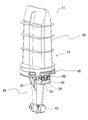
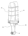
[0039] 여기서, 상기 스프레이 건에 대해 도면을 참조하여 설명하면, 도 1 및 도 2는 본 실시예에 있어서의 스프레이 건(11)을 나타내는 사시도이고, 또, 도 3은 본 실시예에 있어서의 스프레이 건(11)의 구조를 설명하기 위한 도면이며, 본 실시예에 있어서 스프레이 건(11)은, 스프레이 건 본체와, 이 스프레이 건 본체에 도료를 공급하는 도료 공급수단을 가지고 있다. 즉, 도 1, 2에 있어서 12가 스프레이 건 본체, 13이 도료 공급수단이며, 도료 공급수단(13)의 하부에 스프레이 건 본체(12)가 연결되어 있고, 본 실시예에 있어서, 스프레이 건 본체(12)와 도료 공급수단(13)은, 일체로 되어 있다.Here, when the spray gun is described with reference to the drawings, FIGS. 1 and 2 are perspective views showing the
[0040] 우선, 상기 스프레이 건 본체(12)에 대해 설명하면, 도 4는 상기 스프레이 건 본체(12)의 구조를 설명하기 위한 단면도이며, 본 실시예에 있어서 상기 스프레이 건 본체(12)는, 도료 공급로가 내부에 형성되어, 상기 도료 공급수단(13)으로부터 공급된 도료를 받아들이고, 이 받아들인 도료를 분사할 수 있게 되어 있다.First, when the
[0041] 즉, 도면에 있어서 14가 도료 공급로이며, 이 도료 공급로(14)는, 상기 도료 공급수단(13)으로부터 공급된 도료를 받아들이는 도료 받이구(受入口)(14a)와, 이 도료 받이구(14a)로부터 받아들인 도료를 작업물을 향해 분사하기 위한 도료 분사구(噴射口)(14b)를 가지고 있으며, 도료 받이구(14a)는 스프레이 건 본체(12)의 측벽 측에서 개구로 되어 있고, 도료 분사구(14b)는, 상기 스프레이 건 본체(12)의 선단면에서 개구로 되어 있다.That is, in the drawing, 14 is a paint supply path, and the
[0042] 다음으로, 도 4에 있어서 15는, 상기 도료 분사구(14b)를 개폐하기 위한 니들이며, 이 니들(15)은, 니들 가동 수단에 의해, 상기 스프레이 건 본체(12)의 전후 방향으로 이동 가능하게 되어 있고, 전진함으로써 상기 도료 분사구(14b)를 폐쇄하며, 후퇴함으로써 상기 도료 분사구(14b)를 개방하는 것으로 되어 있다.Next, in FIG. 4, 15 is a needle for opening and closing the
[0043] 여기서, 상기 니들 가동 수단에 대해 설명하면, 본 실시예에 있어서 상기 도료 공급로(14)는, 상기 도료 분사구(14b)로부터 스프레이 건 본체(12)의 후방 측으로 임의의 거리만큼 연장된 후에, 스프레이 건 본체(12)의 측벽 방향을 향해 진로를 바꾸어 나아가며, 스프레이 건 본체(12)의 측벽에 있어서 도료 받이구(14a)가 개구되어 있다.Here, with reference to the needle moving means, in the present embodiment, the
[0044] 한편, 상기 니들(15)은, 스프레이 건 본체(12) 내에 있어서, 스프레이 건 본체(12)의 중심부분을 관통하여 설치되고, 선단 측은 상기 도료 공급로(14) 내에 위치하며, 기단 측은, 스프레이 건 본체(12) 내에 있어서, 상기 도료 공급로(14) 내부로부터 벗어나 도료 공급로(14)로부터 돌출되고, 돌출된 부분에는, 스프레이 건 본체(12) 내에 앞뒤 방향으로 이동 가능한 피스톤(16)이 고정되어 있다. 그리고, 피스톤(16)은, 스프링(17)에 의해 스프레이 건 본체(12)의 선단 방향으로 가세되며, 이로써 통상적으로는, 상기 니들(15)은, 피스톤(16)과 함께 스프레이 건 본체(12)의 선단 방향으로 이동하여, 선단 부분에서 도료 분사구(14b)를 폐쇄하고 있다.On the other hand, the
[0045] 다음으로, 상기 스프레이 건 본체(12)의 내부에는, 피스톤(16)의 스프링 반대 측에 에어 챔버(18)가 형성되는 동시에, 기단 측이 스프레이 건 본체(12)의 측벽에서 개구로 되어 있고 선단 측이 상기 에어 챔버(18)에 연결된, 니들 가동용 에어 공급로(19)가 형성되어 있다. 그리고 이 니들 가동용 에어 공급로(19)의 기단 측의 개구에는, 상기 도료 공급수단(13)에 형성된 니들 가동용의 에어 반송로(도시 생략)가 연결되며, 상기 도료 공급수단(13)으로부터 에어가 공급됨에 따라, 니들 가동용 에어 공급로(19)를 통해 상기 에어 챔버(18) 내에 에어가 공급되어, 피스톤(16)이 스프레이 건 본체(12) 내의 기단 측으로 가압되고, 이에 따라, 니들(15)이 스프레이 건 본체(12)의 기단 측으로 이동하여, 니들(15)의 선단에 의한 도료 분사구(14b)의 폐쇄가 해제된다.Next, in the interior of the
[0046] 따라서, 본 실시예에서는, 에어 챔버(18)에 에어를 공급하거나, 혹은 공급되어 있는 에어를 빼냄으로써, 니들(15)을 가동하여 도료 분사구(14b)를 개폐할 수가 있다. 단, 본 발명에서는, 반드시 위에서 기술한 바와 같은 구성으로 니들(15)을 가동할 필요는 없고, 니들(15)을 스프레이 건 본체(12)의 전후 방향으로 이동시킴으로써 도료 분사구(14b)를 개폐할 수 있다면, 어떠한 구성으로 해도 된다.Therefore, in the present embodiment, by supplying air to the
[0047] 다음으로, 도면에 있어서 20은, 무화 에어 공급로이다. 즉, 본 실시예에 있어서 상기 스프레이 건 본체(12)에는, 도료 분사구(14b)로부터 토출된 도료를 무화(霧化)하여 작업물을 향해 분사하기 위한 무화 에어 공급로(20)가 형성되어 있다. 그리고, 이 무화 에어 공급로(20)는, 선단부가 상기 도료 분사구(14b) 주위의 임의의 장소에서 개구로 되어 있으며, 기단 측은, 상기 도료 공급수단(13)에 형성된 무화 에어 반송로(도시 생략)에 연통되고, 도료 공급수단(13)에 형성된 무화 에어 반송로를 통해 에어가 공급되면, 무화 에어 공급로(20)를 통해 도료 분사구(14b)의 주위에 무화 에어가 공급되어, 도료 분사구(14b)로부터 토출된 도료를 무화할 수 있게 되어 있다.Next, 20 in the drawing is an atomizing air supply path. That is, in the present embodiment, the spray gun
[0048] 다음으로, 도면에 있어서 21은 패턴 에어 공급로이다. 즉, 본 실시예에 있어서 스프레이 건 본체(12)에는, 무화 에어에 의해 무화된 도료의 분출 패턴을 임의의 패턴으로 변경하기 위한 패턴 에어 공급로(21)가 형성되어 있다. 그리고, 이 패턴 에어 공급로(21)는, 선단부는, 상기 무화 에어 공급로(20)의 선단부 개구부보다 외측에서 개구(2101)로 되어 있고, 기단 측은, 상기 도료 공급수단(13)에 형성된 패턴 에어 반송로(도시 생략)에 연통되며, 도료 공급수단(13)에 형성된 패턴 에어 반송로를 통해 에어가 공급되면, 패턴 에어 공급로(21)를 통해, 상기 무화 에어 공급로(20)의 선단부 개구부의 주위에 패턴 에어가 공급되어, 무화 에어에 의해 무화된 도료의 분출 패턴을 변경할 수 있게 되어 있다.Next, in the drawing, 21 is a pattern air supply path. That is, in this embodiment, the pattern
[0049] 다음으로, 스프레이 건 본체(12)와 함께 스프레이 건(11)을 구성하는 도료 공급수단(13)에 대해 설명하면, 도 1에 있어서 본 실시예의 도료 공급수단(13)은, 매니폴드(23)와, 이 매니폴드(23)에 연결된 케이싱(24)을 구비하고 있다. 그리고, 케이싱(24)은, 내부가 밀폐 상태로 되어 있으며, 내부에는 도료용 파우치(25)가 수용되어 있다.Next, with reference to the paint supply means 13 constituting the
[0050] 여기서, 도 3을 참조하여 상기 매니폴드(23)에 대해 설명하면, 상기 매니폴드(23)는, 스프레이 건 본체(12)의 상부에 연결되어 있으며, 도료 토출부(26)를 가지고 있는 동시에, 이 도료 토출부(26)는, 도시되지 않은 도료 반송로를 통해, 스프레이 건 본체(12)의 도료 받이구(14a)에 통해 있다.Here, referring to FIG. 3, the manifold 23 will be described. The manifold 23 is connected to an upper portion of the
[0051] 또, 매니폴드(23)는, 케이싱(24)의 내부에 작동액을 공급하기 위한 작동액 공급부(27)와, 케이싱(24)의 내부에 공급된 작동액을 배출하기 위한 작동액 배출부(28)(도 6 참조)를 구비하고 있다.In addition, the manifold 23, the working
[0052] 한편, 상기 도료용 파우치(25)는, 주머니 형상으로 되어 있고, 내부에 도료를 충전할 수 있는 동시에, 상기 도료 토출부(26)에 연결된 도료 토출구(吐出口)(30)를 가지고 있다. 그리고 이로써, 도료용 파우치(25) 내의 도료를, 도료 토출부(26) 및 도시되지 않은 도료 반송로, 및 스프레이 건 본체(12)의 도료 받이구(14a)를 통해, 스프레이 건 본체(12)에 공급할 수 있게 되어 있다.On the other hand, the
[0053] 여기서, 상기 도료용 파우치(25)에 대해 설명하면, 본 실시예의 도료용 파우치(25)는, 다층 필름으로 구성되며, 내부에 충전된 도료를 토출함에 따라 체적이 작아지고, 작아진 상태에서 내부에 도료를 충전함에 따라 원래의 크기로 돌아오게 되어 있다.Here, with reference to the
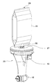
[0054] 또한, 여기서 도 5, 6은 상기 케이싱(24)을 제거한 상태의 스프레이 건(11)을 나타내는 사시도이며, 도면에 있어서 29는, 케이싱(24) 내에 공급한 작동액을 케이싱(24)으로부터 배출하여 핸드 유닛 측으로 되돌리기 위한 작동액 배출관이고, 이 작동액 배출관(29)은, 하단이 작업액 배출부(28)에 연결되고, 상단은 케이싱(24) 내에 있어서의 상단 부분에서 개구되어 있다.In addition, here, Figures 5 and 6 is a perspective view showing a
[0055] 또, 매니폴드(23)의 측면 측에는, 작동액 공급구(供給口)(31), 작동액 배출구(32)가 형성되며, 작동액 공급구(31)는, 상기 작동액 공급부(27)에 통해 있고, 작동액 배출구(32)는, 상기 작동액 배출부(28)에 통해 있다.In addition, on the side of the manifold 23, the working fluid supply port (供給 口) 31, the working
[0056] 그리고 이러한 구성에 의해, 도료용 파우치(25)에 도료가 충전되어 있는 상태에서, 작동액 배출부(28)로부터의 작동액의 배출을 불가능하게 하고, 작동액 공급구(31)를 통해 작동액 공급부(27)로부터 케이싱(24) 내부로 작동액을 공급해 가면, 작동액에 의해 도료용 파우치(25)가 압박된다. 그렇게 되면, 도료용 파우치(25)는, 작동액에 의해 압박됨에 따라 작아지는 동시에, 이에 따라 도료용 파우치(25) 내의 도료는, 도료 토출구(30)로부터 도료 토출부(26)로 토출되며, 나아가, 매니폴드 내의 도료 반송로(도시 생략)를 통해, 스프레이 건 본체(12)의 도료 받이구(14a)로부터, 스프레이 건 본체(12)로 공급된다.And by such a configuration, in the state where the paint is filled in the
[0057] 한편, 작동액 배출부(28)로부터의 작동액의 배출을 가능하게 한 상태에서, 작동액 공급부(27)로부터 케이싱(24) 내에 작동액을 공급해 가면, 케이싱(24) 내부가 작업액으로 충전된 후에, 케이싱(24) 내에 공급되어 있는 작동액은, 케이싱(24) 내의 상단에 개구되어 있는 작동액 배출관(29), 작동액 배출부(28) 및 작동액 배출구(32)로부터 케이싱(24)의 외부로 배출된다. 그리고 이로써, 케이싱(24)을 통해, 작동액을 되돌릴 수 있는 동시에, 작동액 배출관의 상단이 케이싱(24) 내에 있어서의 상단 부분에서 개구되어 있기 때문에, 작동액을 되돌리는 과정에서, 케이싱(24) 내의 에어를 빼내는 작업 등을 용이하게 행할 수 있게 된다.On the other hand, in the state that enables the discharge of the working fluid from the working
[0058] 나아가, 매니폴드(23)의 측면에는 3개의 에어 공급구(33)가 형성되어 있으며, 이들 에어 공급구(33)는 각각, 도료 공급수단(13)에 형성된 니들 가동용의 에어 반송로, 무화 에어 반송로, 패턴 에어 반송로(모두 도시 생략)에 통해 있는 동시에, 위에서 기술한 바와 같이, 이들 니들 가동용의 에어 반송로, 무화 에어 반송로, 패턴 에어 반송로는 각각, 스프레이 건 본체(12)에 형성된 니들 가동 에어 공급로(19), 무화 에어 공급로(20), 및 패턴 에어 공급로(21)에 통해 있다.Further, on the side of the manifold 23, three
[0059] 이 때문에, 에어 공급구(33)의 각각으로부터 에어를 주입함으로써, 스프레이 건 본체(12)에 형성된 니들 가동용 에어 공급로(19), 무화 에어 공급로(20), 및 패턴 에어 공급로(21)에 에어를 공급할 수 있으며, 이로써, 니들(15)을 가동하여 도료 분사구(14b)를 개방하는 동시에, 도료 공급로(14)에 공급된 도료를, 임의의 패턴으로 무화하여 도료 분사구(14b)로부터 분사할 수가 있다.For this reason, by injecting air from each of the
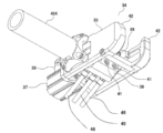
[0060] 다음으로, 스프레이 건(11)을 도장 로봇(4)에 부착하기 위한 핸드 유닛에 대해 설명하면, 도 7 및 도 8은 본 실시예의 핸드 유닛(34)을 나타내는 사시도로서, 도 7은 상방으로부터 본 도면이고, 도 8은 하측으로부터 본 도면이다. 그리고, 상기 핸드 유닛(34)은, 핸드 유닛 본체를 가지고 있으며, 이 핸드 유닛 본체가 도장 로봇(4)의 아암 등에 부착된다.Next, when describing the hand unit for attaching the
[0061] 즉, 도면에 있어서 35가 핸드 유닛 본체이고, 이 핸드 유닛 본체(35)는, 상방이 개방된 상자 형상으로 되어 있으며, 내부에는 가동부(可動部, 36)를 가지고 있다. 그리고, 이 가동부(36)는, 에어 실린더(37)에 의해, 진퇴 가능하게 되어 있다. 또한, 도면에 있어서 38은 에어 실린더(37)에 에어를 공급하기 위한 에어 공급관이다.That is, in the drawing, 35 is a hand unit main body, and the hand unit
[0062] 다음으로, 도면에 있어서 39는 작동액 공급용 조인트, 40은 작동액 배출용 조인트이다. 즉, 상기 가동부(36)에는, 작동액 공급용 조인트(39)와 작동액 배출용 조인트(40)가 구비되어 있다. 그리고, 이들 작동액 공급용 조인트(39)와 작동액 배출용 조인트(40)는, 기단 부분에는 작동액 공급수단이 연결되어 있고, 선단 부분은, 매니폴드(23)에 형성된 작동액 공급구(31), 작동액 배출구(32)에 연결할 수 있게 되어 있다. 따라서 본 실시예에서는, 매니폴드(23)의 작동액 공급구(31), 작동액 배출구(32)의 각각에 작동액 공급용 조인트(39), 작동액 배출용 조인트(40)를 연결함으로써, 케이싱(24) 내부에 대한 작동액의 공급, 케이싱(24) 내부의 작동액의 배출을 수행할 수가 있다. 또한, 도면에 있어서 46, 47은 작동액 공급수단의 일부로서, 46이 작동액 공급로, 47이 작동액 배출로이다.Next, in the drawing, 39 is a joint for supplying the working fluid, and 40 is a joint for discharging the working fluid. That is, the
[0063] 다음으로, 도면에 있어서 41은 에어 공급용 조인트이다. 즉, 상기 가동부(36)에는 또한, 매니폴드(23)의 측면에 형성된 3개의 에어 공급구(33)가 연결되는 에어 공급용 조인트(41)가 구비되어 있으며, 이 에어 공급용 조인트(41)는, 기단 측에는 에어 공급수단이 연결되어 있다. 따라서, 본 실시예에서는, 매니폴드(23)의 3개의 에어 공급구(33)의 각각에 에어 공급용 조인트(41)를 연결함으로써, 스프레이 건 본체(12)에 형성된 니들 가동 에어 공급로(19), 무화 에어 공급로(20), 및 패턴 에어 공급로(21)에 에어를 공급할 수가 있다. 또한, 도 8에 있어서 48은, 에어 공급수단의 일부로서, 에어 공급용 조인트(41)에 에어를 공급하기 위한 에어관이다.Next, in the drawing, 41 is a joint for supplying air. That is, the
[0064] 이와 같이, 본 실시예에서는, 작동액 공급수단이 연결되는 작동액 공급용 조인트(39) 및 작동액 배출용 조인트(40)와, 에어 공급수단이 연결되는 에어 공급용 조인트(41)가 핸드 유닛(34)에 구비되어 있어, 스프레이 건(11)을 핸드 유닛(34)에 장착하는 것만으로, 작동액 공급수단이나 에어 공급수단과 스프레이 건을 연결할 수 있으며, 나아가, 스프레이 건(11)을 핸드 유닛(34)으로부터 떼어내는 것만으로 작동액 공급수단이나 에어 공급수단과 스프레이 건 간의 연결을 해제할 수 있기 때문에, 도료의 색을 교체할 때에는, 종래의 파우치 건과 같이, 작동액 공급수단이나 에어 공급수단과 스프레이 건 간의 연결을 해제할 필요가 없게 되어, 작업이 용이해졌다.In this way, in the present embodiment, the working fluid supply joint is connected to the working fluid supply joint 39 and the working fluid discharge joint 40 and the air supply means is connected to the air supply joint 41 Is provided in the
[0065] 다음으로, 도면에 있어서 42는, 핸드 유닛 본체(35)에 스프레이 건(11)을 지지하기 위한 걸림고정 클로(claw)부이다. 즉, 상기 핸드 유닛 본체(35)에는 걸림고정 클로부(42)가 형성되어 있는 한편, 상기 스프레이 건(11)에 있어서의 매니폴드(23)에는, 상기 걸림고정 클로부(42)가 걸림고정되는 걸림고정 홈(43)이 형성되어 있다(도 2, 5, 6 참조). 그리고, 걸림고정 홈(43)에 걸림고정 클로부(42)를 삽입함으로써, 핸드 유닛 본체(35)에 스프레이 건(11)을 지지할 수 있게 되어 있다.Next, in the drawing, 42 is a locking claw part for supporting the
[0066] 그리고, 본 실시예에 있어서는, 걸림고정 홈(43)에 걸림고정 클로부(42)를 삽입함으로써 핸드 유닛 본체(35)에 스프레이 건(11)을 지지한 상태에 있어서, 상기 가동부(36)를 전진시킴으로써, 작동액 공급용 조인트(39)와 작동액 공급구(31), 작동액 배출용 조인트(40)와 작동액 배출구(32), 및 3개의 에어 공급용 조인트(41)와 3개의 에어 공급구(33)의 각각을 연결시키며, 이에 따라 핸드 유닛(34)에 스프레이 건(11)을 장착할 수 있게 되어 있다. 한편, 핸드 유닛(34)에 스프레이 건(11)이 장착되어 있는 상태에서 가동부(36)를 후퇴시킴으로써, 작동액 공급용 조인트(39)와 작동액 공급구(31), 작동액 배출용 조인트(40)와 작동액 배출구(32), 및 3개의 에어 공급용 조인트(41)와 3개의 에어 공급구(33)의 연결을 해제하여, 핸드 유닛(34)으로부터 스프레이 건(11)을 떼어낼 수 있게 되어 있다.In addition, in the present embodiment, in the state in which the
[0067] 또한, 도 7에 있어서 44는 연결 핀이며, 한편, 도 1에 있어서 45는 삽입 구멍이다. 즉, 본 실시예에 있어서 상기 가동부(36)에는, 작동액 공급용 조인트(39)와 작동액 배출용 조인트(40) 사이에, 전방을 향해 연결 핀(44)이 돌출 설치되어 있는 한편, 스프레이 건(11)에 있어서의 작동액 공급구(31)와 작동액 배출구(32) 사이에는, 연결 핀(44)이 삽입되는 삽입 구멍(45)이 형성되어 있다. 그리고 이로써, 상기 가동부(36)를 전진시켰을 때에, 삽입 구멍(45) 내에 연결 핀(44)이 삽입됨에 따라, 스프레이 건(11)을 핸드 유닛(34)에 연결할 수 있게 되어 있다.In addition, 44 in FIG. 7 is a connecting pin, while 45 in FIG. 1 is an insertion hole. That is, in the present embodiment, the
[0068] 다음으로, 이와 같이 구성되는 본 실시예의 도장용 스프레이 건의 사용 방법에 대해 설명하면, 도 9는 본 실시예의 스프레이 건 장치를 이용한 도장 장치를 나타낸 도면으로서, 도장기(塗裝機, 4)로서의 도장 로봇(4)에 본 실시예의 스프레이 건 장치를 장착한 상태를 나타낸 도면이다.Next, when explaining the method of using the spray gun for painting of the present embodiment configured as described above, FIG. 9 is a view showing a painting apparatus using the spray gun device of the present embodiment, a painting machine (塗裝 機, 4 It is the figure which showed the state which attached the spray gun device of this embodiment to the
[0069] 즉, 도 9에 있어서 도장 로봇(4)은, 기대(基臺, 5)에 세워 설치(立設)된 본체 기둥(pillar)(401)을 가지고 있으며, 본체 기둥(401)에는 제1 아암(402)이 상하 방향으로 회동(回動) 가능하게 연결되어 있고, 제1 아암(402)에는 제2 아암(403)이 상하 방향으로 회동 가능하게 연결되어 있다. 또, 제2 아암(403)의 선단 부분에는, 길이가 긴 볼 나사 스플라인(404)이 연결되어 있으며, 본 실시예에 있어서 이 볼 나사 스플라인(404)은, 제2 아암(403)의 폭 방향, 즉, 좌우 방향으로 이동 가능한 동시에, 원주 방향을 따라 회동 가능하게 되어 있다.That is, in FIG. 9, the
[0070] 또한, 도면에 있어서 6은, 작업물이 부착된 지그(jig)를 고정하기 위한 작업물 고정용 테이블이다. 그리고, 본 실시예에 있어서 상기 작업물 고정용 테이블(6)은, 양단(兩端)에 상기 지그를 고정할 수 있는 한 쌍의 고정용 아암(601)을 구비하는 동시에, 이 한 쌍의 고정용 아암(601)은, 기대(基臺, 5)에 회동 가능하게 연결한 연결부(602)에 의해 연결되어 있으며, 연결부(602)를 회동함으로써, 작업물을 교체할 수 있게 되어 있다. 즉, 일방(一方)의 고정용 아암(601)에 고정된 작업물을 도장하고 있을 때, 다른 고정용 아암(601)에 다음의 도장 대상인 작업물이 부착된 지그를 고정시켜 두고, 일방의 고정용 아암(601)에 고정된 작업물의 도장이 완료된 후에, 연결부(602)를 회동함으로써, 다른 고정용 아암(601)에 고정된 작업물을 도장 영역으로 이동시켜 곧바로 도장할 수 있게 되어 있다.In addition, in the drawing, 6 is a work fixing table for fixing a jig to which a work is attached. In addition, in the present embodiment, the work fixing table 6 includes a pair of fixing
[0071] 그리고, 본 실시예의 스프레이 건 장치는, 도장 로봇(4)에 있어서의 볼 나사 스플라인(404)의 양단에 장착되어 사용된다. 즉, 상기 볼 나사 스플라인(404)의 양단에 핸드 유닛(34)을 장착하고, 나아가, 핸드 유닛(34)에 있어서의 작동액 공급용 조인트(39)와 작동액 배출용 조인트(40)의 기단 측에 작동액 공급수단을 연결하며, 에어 공급용 조인트(41)에 에어 공급수단을 연결한다.In addition, the spray gun device of the present embodiment is attached to and used at both ends of the
[0072] 그리고 그 후에, 걸림고정 홈(43)에 걸림고정 클로부(42)를 삽입함으로써 핸드 유닛 본체(35)에 스프레이 건(11)을 지지한 상태에 있어서 가동부(36)를 전진시켜, 작동액 공급용 조인트(39)와 작동액 공급구(31), 작동액 배출용 조인트(40)와 작동액 배출구(32), 및 3개의 에어 공급용 조인트(41)와 3개의 에어 공급구(33)의 각각을 연결시키고, 나아가, 삽입 구멍(45) 내에 연결 핀(44)을 삽입함으로써, 핸드 유닛(34)에 스프레이 건(11)을 연결하여, 스프레이 건 본체(12)로부터 작업물을 향해 도료를 분무할 수 있게 된다.And thereafter, by inserting the locking
[0073] 그리고, 색 교체 등을 위해 스프레이 건을 교환할 때에는, 사용이 끝난 스프레이 건(11)만을 핸드 유닛(34)로부터 떼어내고, 아직 사용하지 않은 스프레이 건을 핸드 유닛에 장착하기만 하면 되며, 이로써, 새롭게 작동액 공급수단이나 에어 공급수단과의 연결을 행하지 않고, 새롭게 장착한 스프레이 건으로부터 작업물을 향해 도료를 분무할 수 있게 된다.And, when replacing the spray gun for color replacement, etc., just remove the used spray gun (11) from the hand unit (34), and simply install a spray gun that has not been used to the hand unit. In this way, it is possible to spray the paint from the newly mounted spray gun toward the work without connecting to the new working fluid supply means or air supply means.
[0074] 또한, 본 발명에 있어서는, 핸드 유닛(34)에 연결하는 작동액 공급수단이나 에어 공급수단은 특별히 한정되지 않는다. 따라서, 작동액 공급수단은, 물 등의 작동액을 저장한 작동액 탱크와, 이 작동액 탱크 내의 작동액을 핸드 유닛 측으로 공급하는 펌프를 가지고 있으면 되고, 또, 에어 공급수단은 컴프레서 등의 압축 에어를 공급할 수 있는 것이면 되며, 나아가 이들 펌프, 컴프레서 등을 제어하는 제어 수단을 가지고 있으면 된다.In addition, in the present invention, the operating liquid supply means and the air supply means connected to the
[0075] 그리고, 작동액 공급수단에 있어서의 펌프로서는, 시린지 펌프(syringe pump)를 이용하면 되며, 이로써, 작동액을 케이싱(24) 내에 정량(定量) 공급할 수 있게 되고, 이에 따라, 도료용 파우치(25) 내의 도료를 정량 토출할 수 있게 된다. 또한, 시린지 펌프는 주지의 기술이므로 상세한 설명은 생략하지만, 예컨대, 선단부가 상기 작동액 공급로(46)에 통하는 통 형상의 시린지와, 시린지 내에는 진퇴 가능하게 삽입 설치된 피스톤과, 이 피스톤에 있어서의 시린지의 기단 측에 연결된 피스톤 로드를 구비한 구성으로 하여, 시린지 내에 작동액을 충전한 상태에서 피스톤을 진행시킴으로써, 시린지 내의 작동액을, 핸드 유닛(34)을 통해 케이싱(24) 내에 공급하면 된다.And, as the pump in the operating liquid supply means, a syringe pump (syringe pump) may be used, whereby it is possible to supply a fixed amount of the working liquid into the
[0076] 또, 작동액 배출구(32)는, 작동액 배출로(47)를 통해 작동액 탱크에 연결하면 되며, 이로써, 케이싱(24)으로부터 배출된 작동액을 작동액 탱크에 되돌릴 수 있게 된다.In addition, the working
[0077] 이와 같이, 본 실시예의 도장용 스프레이 건 장치에서는, 도료용 파우치를 구비한 도료 공급수단에 스프레이 건 본체를 일체로 한 스프레이 건을 이용한 도장용 스프레이 건 장치에 있어서, 스프레이 건을 핸드 유닛으로부터 떼어내는 것만으로 작동액 공급수단이나 에어 공급수단과 스프레이 건 간의 연결을 해제할 수 있으며, 또한, 핸드 유닛의 가동부를 진퇴시키는 것만으로, 핸드 유닛에 대한 스프레이 건의 탈부착을 행할 수 있기 때문에, 스프레이 건의 교환이 용이하여, 다수의 작업물의 도장이나 도료의 색 교체 작업을 효율적으로 수행할 수가 있다.As described above, in the spray gun device for painting of the present embodiment, in the spray gun device for painting using a spray gun in which the spray gun body is integral to a paint supply means having a paint pouch, the spray gun is a hand unit Since the connection between the working fluid supply means or the air supply means and the spray gun can be released simply by removing it from the spray gun, the spray gun can be attached or detached to the hand unit simply by moving the moving part of the hand unit back and forth. It is easy to replace the gun, so it is possible to efficiently perform the color replacement of paints or paints of a large number of works.
[0078] 또, 스프레이 건은, 도료용 파우치를 구비한 도료 공급수단에 스프레이 건 본체를 일체로 한 구성으로 하여, 스프레이 건에 도료를 공급하기 위한 도료 호스를 없앴기 때문에, 도료의 색 교체시에는, 스프레이 건을 교환하기만 하면 되어, 도료나 세정 용제의 낭비를 없앨 수 있어 경제성을 향상시킬 수가 있다.In addition, since the spray gun is configured as an integral part of the spray gun body in a paint supply means having a pouch for paint, the paint hose for supplying the paint to the spray gun is eliminated, and thus the color of the paint is changed. By simply replacing the spray gun, waste of paint or cleaning solvent can be eliminated, and economical efficiency can be improved.
[0079] 본 발명의 도장용 스프레이 건 장치는, 도료 공급수단을 일체로 구비한 스프레이 건을 이용한 도장용 스프레이 건 장치의 전반(全般)에 적용 가능하다.The spray gun device for painting of the present invention is applicable to the entirety of the spray gun device for painting using a spray gun integrally provided with a paint supply means.
[0080] 4; 도장기(도장 로봇)
401; 본체부
402; 넥(neck)부
403; 헤드부
404; 볼 나사 스플라인(아암)
5; 기대(基臺)
6; 작업물 고정용 테이블
601; 고정용 아암
602; 연결부
11; 스프레이 건
12; 스프레이 건 본체
13; 도료 공급수단
14; 도료 공급로
14a; 도료 받이구
14b; 도료 분사구
15; 니들
16; 피스톤
17; 스프링
18; 에어 챔버
19; 니들 가동 에어 공급로
20; 무화 에어 공급로
21; 패턴 에어 공급로
23; 매니폴드
24; 케이싱
25; 도료용 파우치
26; 도료 토출부
27; 작동액 공급부
28; 작동액 배출부
29; 작동액 배출관
30; 도료 토출구
31; 작동액 공급구
32; 작동액 배출구
33; 에어 공급구
34; 핸드 유닛
35; 핸드 유닛 본체
36; 가동부
37; 에어 실린더
38; 에어 공급관
39; 작동액 공급용 조인트
40; 작동액 배출용 조인트
41; 에어 공급용 조인트
42; 걸림고정 클로부
43; 걸림고정 홈부
44; 연결 핀
45; 삽입 구멍
46; 작동액 공급로
47; 작동액 배출로
48; 에어 공급수단4; Sprayer (Painting Robot)
401; Main body
402; Neck
403; Head
404; Ball screw spline (arm)
5; Expectation
6; Workpiece fixing table
601; Fixing arm
602; Connection
11; Spray gun
12; Spray gun body
13; Paint supply means
14; Paint supply route
14a; Paint
14b; Paint nozzle
15; You guys
16; piston
17; spring
18; Air chamber
19; Needle-operated air supply path
20; Atomization air supply furnace
21; Pattern air supply furnace
23; Manifold
24; Casing
25; Pouch for paint
26; Paint outlet
27; Working fluid supply
28; Working fluid outlet
29; Working fluid discharge pipe
30; Paint outlet
31; Working fluid supply port
32; Working fluid outlet
33; Air supply port
34; Hand unit
35; Hand unit body
36; Moving parts
37; Air cylinder
38; Air supply pipe
39; Joint for supplying working fluid
40; Joint for discharging working fluid
41; Air supply joint
42; Clasp
43; Jam fixing groove
44; Connecting pin
45; Insertion hole
46; Working fluid supply path
47; Working fluid discharge path
48; Air supply means
Claims (3)
상기 핸드 유닛(34)은,
작동액 공급수단에 연결되며, 작동액 공급수단으로부터 공급된 작동액을, 상기 스프레이 건에 공급하기 위해 이용되는 작동액 공급용 조인트(39)와,
작동액 공급수단에 연결되며, 상기 스프레이 건에 공급된 작동액을 작동액 공급수단 측으로 되돌리기 위해 이용되는 작동액 배출용 조인트(40)와,
에어 공급수단에 연결되며, 에어 공급수단으로부터 공급된 에어를, 상기 스프레이 건에 공급하기 위한 에어 공급용 조인트(41)를 구비하고,
상기 스프레이 건(11)은,
스프레이 건 본체(12)와, 스프레이 건 본체(12)에 도료를 공급하는 도료 공급수단(13)을 일체로 갖는 동시에,
상기 스프레이 건 본체(12)는,
상기 도료 공급수단(13)으로부터 공급된 도료를 받아들이는 도료 받이구(受入口)(14a)와, 도료 받이구(14a)로부터 받아들인 도료를 작업물(workpiece)을 향해 분사하기 위한 도료 분사구(噴射口)(14b)를 갖는 도료 공급로(14)와,
진퇴 동작에 의해 상기 도료 분사구(14b)를 개폐 가능하도록 한 니들(needle, 15)과,
상기 니들(15)을 진퇴시키기 위한 니들 가동 수단과,
선단이 상기 도료 분사구(14b) 주위의 임의의 장소에서 개구되며, 상기 도료 분사구(14b)의 주위에 에어를 공급함으로써, 상기 도료 분사구(14b)로부터 토출된 도료를 무화(霧化)하는 동시에 이 무화된 도료를 임의의 패턴으로 하여 선단 측에 분사하기 위한 에어 공급로(20, 21)를 구비하고,
상기 도료 공급수단(13)은,
상기 도료 받이구(14a)에 통하는 도료 토출부(26)를 갖는 매니폴드(manifold, 23)와,
상기 매니폴드(23)에 연결된 케이싱(24)과,
상기 케이싱(24) 내에 수용되는 동시에, 상기 도료 토출부(26)에 연결된 도료 토출구(吐出口)(30)를 가지며, 내부에 도료가 충전되는 주머니 형상의 도료용 파우치(25)를 구비하고,
상기 매니폴드(23)는,
상기 작동액 공급용 조인트(39)에 연결되며, 작동액 공급수단으로부터 공급된 작동액을 케이싱(24) 내에 주입하기 위한 작동액 공급구(供給口)(31)와,
상기 작동액 배출용 조인트(40)에 연결되며, 케이싱(24) 내에 주입된 작동액을 작동액 공급수단에 되돌리기 위한 작동액 배출구(32)와,
상기 에어 공급용 조인트(41)에 연결되며, 에어 공급수단으로부터 공급되는 에어를 스프레이 건 본체(12)의 에어 공급로(20, 21)에 공급하기 위한 에어 공급구(33)를 구비하고,
상기 작동액 공급구(31)를 통해 상기 케이싱(24) 내에 작동액을 공급함으로써, 도료용 파우치(25)를 압박하여, 도료용 파우치(25) 내의 도료를 도료 토출부(26)로부터 토출하여 상기 도료 받이구(14a)에 공급하는 것으로 되어 있고,
상기 작동액 공급용 조인트(39)와 작동액 공급구(31)의 연결, 작동액 배출용 조인트(40)와 작동액 배출구(32)의 연결, 및 에어 공급용 조인트(41)와 에어 공급구(33)의 연결을 해제함으로써, 도장기(4)에 장착되어 있는 스프레이 건(11)을 떼어낼 수 있게 하는 동시에,
상기 작동액 공급용 조인트(39)와 작동액 공급구(31), 작동액 배출용 조인트(40)와 작동액 배출구(32), 및 에어 공급용 조인트(41)와 에어 공급구(33)를 연결함으로써, 도장기(4)에 스프레이 건(11)을 장착할 수 있도록 한 것을 특징으로 하는
도장용 스프레이 건 장치.A spray gun device for painting having a hand unit (34) mounted on a sprayer (4) and a spray gun (11) detachably mounted on the hand unit (34),
The hand unit 34,
It is connected to the working fluid supply means, and the working fluid supply joint (39) used to supply the working fluid supplied from the working fluid supply means to the spray gun,
It is connected to the working fluid supply means, and the working fluid discharge joint (40) used to return the working fluid supplied to the spray gun to the working fluid supply means side,
It is connected to the air supply means, and is provided with a joint 41 for supplying air for supplying air supplied from the air supply means to the spray gun,
The spray gun 11,
At the same time, the spray gun body 12 and the paint supply means 13 for supplying paint to the spray gun body 12 are integrally formed,
The spray gun body 12,
A paint receiving port (14a) for receiving the paint supplied from the paint supply means (13), and a paint spraying port for spraying the paint received from the paint receiving port (14a) toward a work piece (workpiece) A coating material supply passage 14 having a 噴射 口) 14b,
Needle (15) to enable the opening and closing of the paint injection hole (14b) by the retreat operation,
Needle moving means for advancing and retreating the needle (15),
The tip is opened at an arbitrary place around the paint jet opening 14b, and by supplying air around the paint jet opening 14b, the paint discharged from the paint jet opening 14b is atomized. Air supply passages (20, 21) for spraying the atomized paint in an arbitrary pattern on the tip side are provided,
The paint supply means 13,
A manifold (23) having a paint discharge portion (26) through the paint receiving opening (14a),
A casing 24 connected to the manifold 23,
It is accommodated in the casing 24, and has a paint ejection opening 30 connected to the paint ejection part 26, and is provided with a pouch 25 for a paint in the shape of a bag filled with paint therein,
The manifold 23,
It is connected to the joint 39 for supplying the working fluid, and the working fluid supply port 31 for injecting the working fluid supplied from the working fluid supply means into the casing 24,
It is connected to the joint 40 for discharging the working fluid, and the working fluid outlet 32 for returning the working fluid injected into the casing 24 to the working fluid supply means,
It is connected to the air supply joint 41, and is provided with an air supply port 33 for supplying air supplied from the air supply means to the air supply paths 20 and 21 of the spray gun body 12,
By supplying the working fluid in the casing 24 through the working fluid supply port 31, the paint pouch 25 is pressed, and the paint in the paint pouch 25 is discharged from the paint ejecting portion 26. It is supposed to be supplied to the paint receiving port 14a,
The connection of the working fluid supply joint 39 and the working fluid supply port 31, the connection of the working fluid discharge joint 40 and the working fluid discharge port 32, and the air supply joint 41 and the air supply port By releasing the connection of 33, the spray gun 11 mounted on the sprayer 4 can be removed, and at the same time
The working fluid supply joint 39 and the working fluid supply port 31, the working fluid discharge joint 40 and the working fluid outlet 32, and the air supply joint 41 and the air supply port 33 By connecting, it characterized in that the spray gun 11 can be mounted on the sprayer (4)
Spray gun device for painting.
상기 핸드 유닛(34)은,
도장기(4)에 장착되는 동시에 스프레이 건(11)을 지지할 수 있는 핸드 유닛 본체(35)와, 상기 핸드 유닛 본체(35)에 진퇴 가능하게 장착된 가동부(可動部, 36)를 갖는 동시에,
가동부(36)에 상기 작동액 공급용 조인트(39), 작동액 배출용 조인트(40) 및 에어 공급용 조인트(41)가 구비되어 있으며,
핸드 유닛 본체(35)에 스프레이 건(11)을 지지한 상태에서 가동부(36)를 진퇴시킴으로써, 작동액 공급용 조인트(39)와 작동액 공급구(31), 작동액 배출용 조인트(40)와 작동액 배출구(32), 및 에어 공급용 조인트(41)와 에어 공급구(33) 간의 연결 또는 연결의 해제를 행할 수 있도록 한 것을 특징으로 하는
도장용 스프레이 건 장치.According to claim 1,
The hand unit 34,
At the same time having a hand unit body 35 capable of supporting the spray gun 11 at the same time as being mounted on the sprayer 4, and a movable part 36 removably mounted on the hand unit body 35 at the same time ,
The movable part 36 is provided with a joint 39 for supplying the working fluid, a joint 40 for discharging the working fluid and a joint 41 for supplying air,
By moving the movable part 36 in a state where the spray gun 11 is supported on the hand unit main body 35, the joint 39 for supplying the working fluid, the supply port 31 for the working fluid, and the joint 40 for discharging the working fluid And the working fluid outlet 32, and the air supply joint 41 and the air supply port 33 can be connected or released.
Spray gun device for painting.
상기 니들 가동 수단은, 상기 니들(15)이 고정되는 동시에 상기 스프레이 건 본체(12) 내에 이동 가능하게 삽입 장착된 피스톤(16)과, 상기 피스톤(16)을 도료 분사구(14b) 측으로 가세(付勢, bias)하는 스프링(17)과, 상기 피스톤(16)을 에어 압력으로 도료 분사구(14b) 반대 측으로 가압하기 위한 에어 공급수단(19)을 구비한 것을 특징으로 하는
도장용 스프레이 건 장치.The method according to claim 1 or 2,
The needle movable means, while the needle 15 is fixed, the piston 16 is movably inserted into the spray gun body 12 and the piston 16 is pushed toward the coating nozzle 14b.勢, characterized in that it comprises a spring (17) to bias, and an air supply means (19) for pressing the piston (16) to the opposite side of the paint injection port (14b) with air pressure.
Spray gun device for painting.
Applications Claiming Priority (2)
| Application Number | Priority Date | Filing Date | Title |
|---|---|---|---|
| JP2018213251A JP7187275B2 (en) | 2018-11-13 | 2018-11-13 | Spray gun equipment for painting |
| JPJP-P-2018-213251 | 2018-11-13 |
Publications (2)
| Publication Number | Publication Date |
|---|---|
| KR20200055641A true KR20200055641A (en) | 2020-05-21 |
| KR102595710B1 KR102595710B1 (en) | 2023-10-27 |
Family
ID=70646152
Family Applications (1)
| Application Number | Title | Priority Date | Filing Date |
|---|---|---|---|
| KR1020190072729A KR102595710B1 (en) | 2018-11-13 | 2019-06-19 | Paint spray gun device |
Country Status (3)
| Country | Link |
|---|---|
| JP (1) | JP7187275B2 (en) |
| KR (1) | KR102595710B1 (en) |
| CN (1) | CN111167637B (en) |
Citations (11)
| Publication number | Priority date | Publication date | Assignee | Title |
|---|---|---|---|---|
| JPS6158073U (en) | 1984-09-20 | 1986-04-18 | ||
| JP2005296750A (en) | 2004-04-08 | 2005-10-27 | Trinity Ind Corp | Coater |
| JP2006347606A (en) | 2005-06-17 | 2006-12-28 | Toyota Motor Corp | Coating tank, and processing method therefor |
| JP2007021452A (en) | 2005-07-21 | 2007-02-01 | Ransburg Ind Kk | Coater and coating cartridge incorporated in the same |
| JP2007319728A (en) | 2006-05-30 | 2007-12-13 | Trinity Ind Corp | Coating system |
| JP2008212857A (en) | 2007-03-06 | 2008-09-18 | Trinity Ind Corp | Coating machine |
| KR20120040655A (en) * | 2010-10-19 | 2012-04-27 | 간사이 페인트 가부시키가이샤 | Spray gun and coating system |
| KR20120072374A (en) * | 2009-09-23 | 2012-07-03 | 랜스버그 인더스트리얼 피니싱 케이.케이. | Electrostatic coating machine employing removable paint cartridge |
| KR20140056000A (en) * | 2012-10-31 | 2014-05-09 | 아네스토 이와타 가부시키가이샤 | Spray gun |
| JP2015123433A (en) * | 2013-12-27 | 2015-07-06 | タクボエンジニアリング株式会社 | Painting syringe gun, painting syringe gun system using syringe gun, method for filling paint to coating syringe gun |
| JP2015229162A (en) * | 2014-06-06 | 2015-12-21 | 東芝機械株式会社 | Gripping and extrusion unit, and painting system |
Family Cites Families (15)
| Publication number | Priority date | Publication date | Assignee | Title |
|---|---|---|---|---|
| JP3245040B2 (en) * | 1996-02-29 | 2002-01-07 | トリニティ工業株式会社 | Electrostatic coating machine |
| US6419663B2 (en) * | 2000-05-18 | 2002-07-16 | John E. Harrold | Mechanically propelled, metered liquid dispenser |
| KR20050005701A (en) * | 2003-07-07 | 2005-01-14 | 현대자동차주식회사 | A painting device |
| CA2537142C (en) * | 2003-08-27 | 2013-05-28 | Toyota Jidosha Kabushiki Kaisha | Electrostatic coating machine and method of cleaning the same |
| JP2006158073A (en) * | 2004-11-29 | 2006-06-15 | Fuji Electric Holdings Co Ltd | Charging/discharging method for capacitor and power conversion equipment |
| WO2006113264A1 (en) * | 2005-04-13 | 2006-10-26 | Illinois Tool Works Inc. | Canister for electrostatic applicators |
| JP2006341199A (en) * | 2005-06-09 | 2006-12-21 | Trinity Ind Corp | Coater |
| SE0501925L (en) * | 2005-08-31 | 2007-03-01 | Ecco Finishing Ab | Spray gun arrangement and method for controlling such |
| JP2008023456A (en) * | 2006-07-21 | 2008-02-07 | Trinity Ind Corp | Coating system and hydraulic liquid for coating using the system |
| KR101044032B1 (en) * | 2006-12-04 | 2011-06-23 | 에이비비 가부시키가이샤 | Paint application cartridge |
| JP2010022889A (en) * | 2008-07-15 | 2010-02-04 | Ransburg Ind Kk | Spray device with movable needle |
| US8544686B2 (en) * | 2009-07-10 | 2013-10-01 | Aervoe Industries, Inc. | System for dispensing sprayable material |
| JP4812871B2 (en) * | 2009-10-21 | 2011-11-09 | トヨタ自動車株式会社 | Paint filling device |
| JP6293626B2 (en) * | 2014-09-19 | 2018-03-14 | トリニティ工業株式会社 | Coating method and coating apparatus |
| JP3210510U (en) * | 2017-03-08 | 2017-05-25 | タクボエンジニアリング株式会社 | Spray gun for painting |
-
2018
- 2018-11-13 JP JP2018213251A patent/JP7187275B2/en active Active
-
2019
- 2019-06-14 CN CN201910513592.XA patent/CN111167637B/en active Active
- 2019-06-19 KR KR1020190072729A patent/KR102595710B1/en active IP Right Grant
Patent Citations (11)
| Publication number | Priority date | Publication date | Assignee | Title |
|---|---|---|---|---|
| JPS6158073U (en) | 1984-09-20 | 1986-04-18 | ||
| JP2005296750A (en) | 2004-04-08 | 2005-10-27 | Trinity Ind Corp | Coater |
| JP2006347606A (en) | 2005-06-17 | 2006-12-28 | Toyota Motor Corp | Coating tank, and processing method therefor |
| JP2007021452A (en) | 2005-07-21 | 2007-02-01 | Ransburg Ind Kk | Coater and coating cartridge incorporated in the same |
| JP2007319728A (en) | 2006-05-30 | 2007-12-13 | Trinity Ind Corp | Coating system |
| JP2008212857A (en) | 2007-03-06 | 2008-09-18 | Trinity Ind Corp | Coating machine |
| KR20120072374A (en) * | 2009-09-23 | 2012-07-03 | 랜스버그 인더스트리얼 피니싱 케이.케이. | Electrostatic coating machine employing removable paint cartridge |
| KR20120040655A (en) * | 2010-10-19 | 2012-04-27 | 간사이 페인트 가부시키가이샤 | Spray gun and coating system |
| KR20140056000A (en) * | 2012-10-31 | 2014-05-09 | 아네스토 이와타 가부시키가이샤 | Spray gun |
| JP2015123433A (en) * | 2013-12-27 | 2015-07-06 | タクボエンジニアリング株式会社 | Painting syringe gun, painting syringe gun system using syringe gun, method for filling paint to coating syringe gun |
| JP2015229162A (en) * | 2014-06-06 | 2015-12-21 | 東芝機械株式会社 | Gripping and extrusion unit, and painting system |
Also Published As
| Publication number | Publication date |
|---|---|
| KR102595710B1 (en) | 2023-10-27 |
| CN111167637A (en) | 2020-05-19 |
| JP7187275B2 (en) | 2022-12-12 |
| JP2020078777A (en) | 2020-05-28 |
| CN111167637B (en) | 2022-04-29 |
Similar Documents
| Publication | Publication Date | Title |
|---|---|---|
| RU2601337C2 (en) | Paint spray gun with possibility of easy cleaning, accessory for paint spray gun and method of their assembly and disassembly | |
| KR101021894B1 (en) | Air atomizing type coating apparatus | |
| CN101970127B (en) | Disposable spray gun cartridge | |
| CN101646500A (en) | Cleaning device for cleaning spray guns | |
| EP1666157B1 (en) | Electrostatic coating machine and method of cleaning the same | |
| JP4764316B2 (en) | Painting system | |
| JP2010022889A (en) | Spray device with movable needle | |
| JPH11262699A (en) | Rotary-atomizing head coater | |
| JP6158073B2 (en) | Syringe gun for painting, a syringe gun system for painting using the syringe gun, and a method for filling paint into a syringe gun for painting | |
| KR20200055641A (en) | Paint spray gun device | |
| JP6293626B2 (en) | Coating method and coating apparatus | |
| JP2011101854A (en) | Nozzle cleaning system | |
| JP7109338B2 (en) | painting system | |
| JP7150576B2 (en) | PAINT FILLING UNIT AND PAINT FILLING APPARATUS INCLUDING THE SAME | |
| JP2013013866A (en) | Paint supply system and paint supply method | |
| KR20080023261A (en) | Device and installation for spraying coating product comprising a reservoir | |
| JP5080786B2 (en) | Painting system | |
| JP3242584U (en) | paint spray gun | |
| JPH0624766U (en) | Coating equipment | |
| WO2022220091A1 (en) | Coating device, cartridge, coating gun body, and method for spraying mixed solution | |
| JP6281910B2 (en) | Coating method and coating apparatus | |
| JP3689837B2 (en) | A set of paint and cleaning couplers | |
| JP2008000649A (en) | Unit type spraying device | |
| JP2023034035A (en) | Coating method | |
| JP4398662B2 (en) | Spray gun for painting |
Legal Events
| Date | Code | Title | Description |
|---|---|---|---|
| A201 | Request for examination | ||
| E902 | Notification of reason for refusal | ||
| E701 | Decision to grant or registration of patent right | ||
| GRNT | Written decision to grant |