KR20200052616A - Color registration in real-time - Google Patents
Color registration in real-time Download PDFInfo
- Publication number
- KR20200052616A KR20200052616A KR1020180135779A KR20180135779A KR20200052616A KR 20200052616 A KR20200052616 A KR 20200052616A KR 1020180135779 A KR1020180135779 A KR 1020180135779A KR 20180135779 A KR20180135779 A KR 20180135779A KR 20200052616 A KR20200052616 A KR 20200052616A
- Authority
- KR
- South Korea
- Prior art keywords
- image
- pattern
- forming apparatus
- synchronization signal
- Prior art date
Links
Images


Classifications
-
- H—ELECTRICITY
- H04—ELECTRIC COMMUNICATION TECHNIQUE
- H04N—PICTORIAL COMMUNICATION, e.g. TELEVISION
- H04N1/00—Scanning, transmission or reproduction of documents or the like, e.g. facsimile transmission; Details thereof
- H04N1/23—Reproducing arrangements
-
- G—PHYSICS
- G03—PHOTOGRAPHY; CINEMATOGRAPHY; ANALOGOUS TECHNIQUES USING WAVES OTHER THAN OPTICAL WAVES; ELECTROGRAPHY; HOLOGRAPHY
- G03G—ELECTROGRAPHY; ELECTROPHOTOGRAPHY; MAGNETOGRAPHY
- G03G15/00—Apparatus for electrographic processes using a charge pattern
- G03G15/01—Apparatus for electrographic processes using a charge pattern for producing multicoloured copies
- G03G15/0105—Details of unit
- G03G15/011—Details of unit for exposing
-
- G—PHYSICS
- G03—PHOTOGRAPHY; CINEMATOGRAPHY; ANALOGOUS TECHNIQUES USING WAVES OTHER THAN OPTICAL WAVES; ELECTROGRAPHY; HOLOGRAPHY
- G03G—ELECTROGRAPHY; ELECTROPHOTOGRAPHY; MAGNETOGRAPHY
- G03G15/00—Apparatus for electrographic processes using a charge pattern
- G03G15/50—Machine control of apparatus for electrographic processes using a charge pattern, e.g. regulating differents parts of the machine, multimode copiers, microprocessor control
- G03G15/5016—User-machine interface; Display panels; Control console
-
- G—PHYSICS
- G03—PHOTOGRAPHY; CINEMATOGRAPHY; ANALOGOUS TECHNIQUES USING WAVES OTHER THAN OPTICAL WAVES; ELECTROGRAPHY; HOLOGRAPHY
- G03G—ELECTROGRAPHY; ELECTROPHOTOGRAPHY; MAGNETOGRAPHY
- G03G15/00—Apparatus for electrographic processes using a charge pattern
- G03G15/01—Apparatus for electrographic processes using a charge pattern for producing multicoloured copies
- G03G15/0105—Details of unit
- G03G15/0131—Details of unit for transferring a pattern to a second base
-
- G—PHYSICS
- G03—PHOTOGRAPHY; CINEMATOGRAPHY; ANALOGOUS TECHNIQUES USING WAVES OTHER THAN OPTICAL WAVES; ELECTROGRAPHY; HOLOGRAPHY
- G03G—ELECTROGRAPHY; ELECTROPHOTOGRAPHY; MAGNETOGRAPHY
- G03G15/00—Apparatus for electrographic processes using a charge pattern
- G03G15/04—Apparatus for electrographic processes using a charge pattern for exposing, i.e. imagewise exposure by optically projecting the original image on a photoconductive recording material
-
- G—PHYSICS
- G03—PHOTOGRAPHY; CINEMATOGRAPHY; ANALOGOUS TECHNIQUES USING WAVES OTHER THAN OPTICAL WAVES; ELECTROGRAPHY; HOLOGRAPHY
- G03G—ELECTROGRAPHY; ELECTROPHOTOGRAPHY; MAGNETOGRAPHY
- G03G15/00—Apparatus for electrographic processes using a charge pattern
- G03G15/50—Machine control of apparatus for electrographic processes using a charge pattern, e.g. regulating differents parts of the machine, multimode copiers, microprocessor control
- G03G15/5054—Machine control of apparatus for electrographic processes using a charge pattern, e.g. regulating differents parts of the machine, multimode copiers, microprocessor control by measuring the characteristics of an intermediate image carrying member or the characteristics of an image on an intermediate image carrying member, e.g. intermediate transfer belt or drum, conveyor belt
- G03G15/5058—Machine control of apparatus for electrographic processes using a charge pattern, e.g. regulating differents parts of the machine, multimode copiers, microprocessor control by measuring the characteristics of an intermediate image carrying member or the characteristics of an image on an intermediate image carrying member, e.g. intermediate transfer belt or drum, conveyor belt using a test patch
-
- G—PHYSICS
- G03—PHOTOGRAPHY; CINEMATOGRAPHY; ANALOGOUS TECHNIQUES USING WAVES OTHER THAN OPTICAL WAVES; ELECTROGRAPHY; HOLOGRAPHY
- G03G—ELECTROGRAPHY; ELECTROPHOTOGRAPHY; MAGNETOGRAPHY
- G03G21/00—Arrangements not provided for by groups G03G13/00 - G03G19/00, e.g. cleaning, elimination of residual charge
- G03G21/14—Electronic sequencing control
-
- H—ELECTRICITY
- H04—ELECTRIC COMMUNICATION TECHNIQUE
- H04N—PICTORIAL COMMUNICATION, e.g. TELEVISION
- H04N1/00—Scanning, transmission or reproduction of documents or the like, e.g. facsimile transmission; Details thereof
- H04N1/0035—User-machine interface; Control console
- H04N1/00352—Input means
- H04N1/00355—Mark-sheet input
- H04N1/00379—Means for enabling correct scanning of a mark sheet or area, e.g. registration or timing marks
-
- H—ELECTRICITY
- H04—ELECTRIC COMMUNICATION TECHNIQUE
- H04N—PICTORIAL COMMUNICATION, e.g. TELEVISION
- H04N1/00—Scanning, transmission or reproduction of documents or the like, e.g. facsimile transmission; Details thereof
- H04N1/00681—Detecting the presence, position or size of a sheet or correcting its position before scanning
- H04N1/00742—Detection methods
- H04N1/00748—Detecting edges, e.g. of a stationary sheet
-
- H—ELECTRICITY
- H04—ELECTRIC COMMUNICATION TECHNIQUE
- H04N—PICTORIAL COMMUNICATION, e.g. TELEVISION
- H04N1/00—Scanning, transmission or reproduction of documents or the like, e.g. facsimile transmission; Details thereof
- H04N1/00681—Detecting the presence, position or size of a sheet or correcting its position before scanning
- H04N1/00763—Action taken as a result of detection
- H04N1/00771—Indicating or reporting, e.g. issuing an alarm
-
- H—ELECTRICITY
- H04—ELECTRIC COMMUNICATION TECHNIQUE
- H04N—PICTORIAL COMMUNICATION, e.g. TELEVISION
- H04N1/00—Scanning, transmission or reproduction of documents or the like, e.g. facsimile transmission; Details thereof
- H04N1/40—Picture signal circuits
-
- H—ELECTRICITY
- H04—ELECTRIC COMMUNICATION TECHNIQUE
- H04N—PICTORIAL COMMUNICATION, e.g. TELEVISION
- H04N1/00—Scanning, transmission or reproduction of documents or the like, e.g. facsimile transmission; Details thereof
- H04N1/40—Picture signal circuits
- H04N1/40056—Circuits for driving or energising particular reading heads or original illumination means
-
- H—ELECTRICITY
- H04—ELECTRIC COMMUNICATION TECHNIQUE
- H04N—PICTORIAL COMMUNICATION, e.g. TELEVISION
- H04N1/00—Scanning, transmission or reproduction of documents or the like, e.g. facsimile transmission; Details thereof
- H04N1/46—Colour picture communication systems
- H04N1/56—Processing of colour picture signals
- H04N1/60—Colour correction or control
- H04N1/603—Colour correction or control controlled by characteristics of the picture signal generator or the picture reproducer
- H04N1/6033—Colour correction or control controlled by characteristics of the picture signal generator or the picture reproducer using test pattern analysis
- H04N1/6044—Colour correction or control controlled by characteristics of the picture signal generator or the picture reproducer using test pattern analysis involving a sensor integrated in the machine or otherwise specifically adapted to read the test pattern
-
- G—PHYSICS
- G03—PHOTOGRAPHY; CINEMATOGRAPHY; ANALOGOUS TECHNIQUES USING WAVES OTHER THAN OPTICAL WAVES; ELECTROGRAPHY; HOLOGRAPHY
- G03G—ELECTROGRAPHY; ELECTROPHOTOGRAPHY; MAGNETOGRAPHY
- G03G2215/00—Apparatus for electrophotographic processes
- G03G2215/01—Apparatus for electrophotographic processes for producing multicoloured copies
- G03G2215/0151—Apparatus for electrophotographic processes for producing multicoloured copies characterised by the technical problem
- G03G2215/0158—Colour registration
-
- H—ELECTRICITY
- H04—ELECTRIC COMMUNICATION TECHNIQUE
- H04N—PICTORIAL COMMUNICATION, e.g. TELEVISION
- H04N2201/00—Indexing scheme relating to scanning, transmission or reproduction of documents or the like, and to details thereof
- H04N2201/0077—Types of the still picture apparatus
- H04N2201/0082—Image hardcopy reproducer
Abstract
Description
화상형성장치는 화상데이터의 생성, 인쇄, 수신, 전송 등을 수행하는 장치로서, 대표적인 예로서, 프린터, 스캐너, 복사기, 팩스 및 이들의 기능을 통합 구현한 복합기 등을 들 수 있다.The image forming apparatus is an apparatus for generating, printing, receiving, and transmitting image data, and examples thereof include printers, scanners, copiers, fax machines, and multifunction machines that incorporate these functions.
칼라 화상을 정확하게 구현하기 위해서는 전사벨트의 주행속도를 감안하여 노광장치에 의한 각 감광드럼(Dy)(Dc)(Dm)(Dk)의 노광 개시 시점을 정확하게 맞추는 것이 중요하며, 이와 같이 한 화상을 형성할 복수의 색상이 정확하게 중첩되도록 노광 개시 시점을 맞추는 것을 칼라 레지스트레이션이라 한다.In order to accurately implement a color image, it is important to precisely match the exposure start time of each photosensitive drum (Dy) (Dc) (Dm) (Dk) by the exposure apparatus in consideration of the traveling speed of the transfer belt. Matching the starting point of exposure so that a plurality of colors to be formed accurately overlap is called color registration.
도 1은 본 개시의 화상형성장치의 간략한 구성의 일 실시 예를 나타내는 블록도,
도 2는 본 개시의 화상형성장치의 구체적인 구성의 일 실시 예를 나타내는 블록도,
도 3은 도 1의 인쇄 엔진의 구체적인 구성의 일 실시 예를 나타내는 도면,
도 4는 본 개시의 이미지 프로세서의 구성의 일 실시 예를 나타내는 블럭도,
도 5는 본 개시의 신호 생성기의 구성의 일 실시 예를 나타내는 블럭도,
도 6은 도 2의 레지스트레이션 장치의 구성의 일 실시 예를 나타내는 블럭도,
도 7 내지 도 9는 본 개시의 일 실시 예에 따라 형성되는 패턴을 설명하기 위한 도면,
도 10은 도 4의 이미지 프로세서의 동작을 설명하기 위한 도면,
도 11은 도 5의 신호 생성기의 동작을 설명하기 위한 도면, 그리고,
도 12는 본 개시의 일 실시 예에 따른 칼라 레지스트레이션 방법을 설명하기 위한 흐름도이다.1 is a block diagram showing an embodiment of a simplified configuration of an image forming apparatus of the present disclosure,
2 is a block diagram showing an embodiment of a specific configuration of the image forming apparatus of the present disclosure,
3 is a view showing an embodiment of a specific configuration of the print engine of FIG. 1,
Figure 4 is a block diagram showing an embodiment of the configuration of the image processor of the present disclosure,
Figure 5 is a block diagram showing an embodiment of the configuration of the signal generator of the present disclosure,
Figure 6 is a block diagram showing an embodiment of the configuration of the registration device of Figure 2,
7 to 9 are views for explaining a pattern formed according to an embodiment of the present disclosure,
10 is a view for explaining the operation of the image processor of FIG. 4,
11 is a view for explaining the operation of the signal generator of FIG. 5, and
12 is a flowchart illustrating a color registration method according to an embodiment of the present disclosure.
이하에서는 도면을 참조하여 다양한 실시예들을 상세히 설명한다. 이하에서 설명되는 실시예들은 여러 가지 상이한 형태로 변형되어 실시될 수도 있다. 실시예들의 특징을 보다 명확히 설명하기 위하여 이하의 실시 예들이 속하는 기술분야에서 통상의 지식을 가진 자에게 널리 알려져 있는 사항들에 관해서 자세한 설명은 생략한다.Hereinafter, various embodiments will be described in detail with reference to the drawings. The embodiments described below may be implemented in various different forms. In order to more clearly describe the features of the embodiments, detailed descriptions of the items well known to those of ordinary skill in the art to which the following embodiments pertain will be omitted.
한편, 본 명세서에서 어떤 구성이 다른 구성과 "연결"되어 있다고 할 때, 이는 ‘직접적으로 연결’되어 있는 경우뿐 아니라, ‘그 중간에 다른 구성을 사이에 두고 연결’되어 있는 경우도 포함한다. 또한, 어떤 구성이 다른 구성을 "포함"한다고 할 때, 이는 특별히 반대되는 기재가 없는 한, 그 외 다른 구성을 제외하는 것이 아니라 다른 구성들 더 포함할 수도 있다는 것을 의미한다.Meanwhile, in the present specification, when a component is "connected" to another component, this includes not only "directly connected" but also "connected with other components in between". In addition, when it is said that a configuration "includes" another configuration, this means that unless otherwise stated, other configurations are not excluded, but may also include other configurations.
본 명세서에서 “화상 형성 작업(image forming job)”이란 화상의 형성 또는 화상 파일의 생성/저장/전송 등과 같이 화상과 관련된 다양한 작업들(e.g. 인쇄, 스캔 또는 팩스)을 의미할 수 있으며, “작업(job)”이란 화상 형성 작업을 의미할 뿐 아니라, 화상 형성 작업의 수행을 위해서 필요한 일련의 프로세스들을 모두 포함하는 의미일 수 있다.In this specification, “image forming job” may mean various jobs (eg print, scan, or fax) related to images, such as image formation or image file creation / storage / transmission. (job) ”may mean not only an image forming job, but also a series of processes necessary for performing the image forming job.
또한, “화상형성장치”란 컴퓨터와 같은 단말장치에서 생성된 인쇄 데이터를 기록 용지에 인쇄하는 장치를 말한다. 이러한 화상형성장치의 예로는 복사기, 프린터, 팩시밀리 또는 이들의 기능을 하나의 장치를 통해 복합적으로 구현하는 복합기(multi-function printer, MFP)등을 들 수 있다. 프린터(printer), 스캐너(scanner), 팩스기(fax machine), 복합기(multi-function printer, MFP) 또는 디스플레이 장치 등과 같이 화상 형성 작업을 수행할 수 있는 모든 장치들을 의미할 수 있다.In addition, "image forming apparatus" refers to a device that prints print data generated by a terminal device such as a computer on a recording sheet. Examples of such an image forming apparatus include a copier, a printer, a facsimile, or a multi-function printer (MFP) that implements these functions in a complex manner through a single device. It may mean any device capable of performing image forming operations, such as a printer, a scanner, a fax machine, a multi-function printer (MFP), or a display device.
또한, “인쇄 데이터”란 프린터에서 인쇄 가능한 포맷으로 변환된 데이터를 의미할 수 있다. 한편, 프린터가 다이렉트 프린팅을 지원한다면, 파일 그 자체가 인쇄 데이터가 될 수 있다.Also, “print data” may mean data converted to a format that can be printed by a printer. On the other hand, if the printer supports direct printing, the file itself can be print data.
또한, “사용자”란 화상형성장치를 이용하여, 또는 화상형성장치와 유무선으로 연결된 디바이스를 이용하여 화상 형성 작업과 관련된 조작을 수행하는 사람을 의미할 수 있다. 또한, “관리자”란 화상형성장치의 모든 기능 및 시스템에 접근할 수 있는 권한을 갖는 사람을 의미할 수 있다. “관리자”와 “사용자”는 동일한 사람일 수도 있다.Also, “user” may refer to a person who performs an operation related to an image forming operation using an image forming apparatus or a device connected to the image forming apparatus by wire or wireless. In addition, "administrator" may mean a person who has authority to access all functions and systems of the image forming apparatus. "Administrator" and "User" may be the same person.
도 1은 본 개시의 화상형성장치의 간략한 구성의 일 실시 예를 나타내는 블록도이다.1 is a block diagram showing an embodiment of a simplified configuration of an image forming apparatus of the present disclosure.
도 1을 참조하면, 화상형성장치(100)는 통신 장치(110), 인쇄 엔진(200) 및 프로세서(120)로 구성될 수 있다.Referring to FIG. 1, the image forming apparatus 100 may be composed of a
통신 장치(110)는 인쇄 제어 단말장치(미도시)와 연결되며, 인쇄 제어 단말장치로부터 인쇄 데이터를 수신할 수 있다. 여기서 인쇄 제어 단말장치는 인쇄 데이터를 제공하는 전자 장치로, PC, 노트북, 태블릿 PC, 스마트폰, 서버 등일 수 있다.The
이러한 통신 장치(110)는 화상형성장치(100)를 외부 장치와 연결하기 위해 형성되고, 근거리 통신망(LAN: Local Area Network) 및 인터넷망을 통해 단말장치에 접속되는 형태뿐만 아니라, USB(Universal Serial Bus) 포트 또는 무선 통신(예를 들어, WiFi 802.11a/b/g/n, NFC, Bluetooth) 포트를 통하여 접속되는 형태도 가능하다. 이러한 통신 장치(110)는 송수신부(transceiver)로 지칭될 수도 있다.The
인쇄 엔진(200)은 화상을 형성한다. 구체적으로, 인쇄 엔진(200)은 복수의 감광 드럼을 이용하여 흑백 또는 컬러 화상을 인쇄용지에 형성할 수 있다.The print engine 200 forms an image. Specifically, the print engine 200 may form a black and white or color image on printing paper using a plurality of photosensitive drums.
그리고 인쇄 엔진(200)은 컬러 레지스트레이션을 위한 기설정된 패턴을 중간 전사 벨트에 형성할 수 있다. 여기서 기설정된 패턴은 주주사 오프셋 및 부주사 오프셋을 동시에 보정할 수 있는 패턴일 수 있으며, 주주사 오프셋만을 보정하기 위한 제1 패턴 또는 부주사 오프셋만을 보정하기 위한 제2 패턴일 수도 있다.In addition, the print engine 200 may form a predetermined pattern for color registration on the intermediate transfer belt. Here, the preset pattern may be a pattern capable of simultaneously correcting the main scan offset and the sub scan offset, or may be a first pattern for correcting only the main scan offset or a second pattern for correcting only the sub scan offset.
프로세서(120)는 화상형성장치(100) 내의 각 구성을 제어한다. 구체적으로, 프로세서(120)는 인쇄 제어 단말장치(미도시)로부터 인쇄 데이터를 수신하면, 수신된 인쇄 데이터에 대한 파싱 등의 동작을 통하여 렌더링을 수행하여 인쇄 이미지를 생성할 수 있다. 여기서 생성된 인쇄 이미지는 이진 데이터일 수 있다.The
이러한 프로세서(130)는 CPU와 같은 단일 장치로 구성될 수 있으며, 클럭 발생 회로, CPU, 그래픽 프로세서 등의 복수의 장치로 구성될 수도 있다. 예를 들어, 후술하는 동작 중 비디오 신호 생성과 관련된 일부 동작은 별도의 이미지 프로세서로 구현될 수 있다.The
프로세서(120)는 인쇄 데이터의 화상 형성과 관련된 인쇄 속도를 결정한다. 구체적으로, 프로세서(120))는 인쇄용지의 종류(구체적으로, 정작 요구 시간) 및 인쇄 엔진(200)의 속도 등을 고려하여 화상 형성과 관련된 인쇄 속도를 결정할 수 있다.The
그리고 프로세서(120)는 결정된 인쇄 속도에 기초하여 지간 거리 및 지간 속도를 결정할 수 있다. 여기서 지간 구간이라, 인쇄용지의 이송 경로 상에서 인쇄용지들 간의 거리를 의미한다.In addition, the
그리고 프로세서(120)는 결정된 지간 거리에 대응되는 레지스트레이션 패턴을 결정할 수 있다. 예를 들어, 결정된 지간 거리가 짧은 경우, 프로세서(120)는 패턴의 길이가 짧은 패턴(예를 들어, 주주사 방향 오프셋 보정을 위한 패턴 또는 부주사 방향 오프셋 보정을 위한 패턴)을 레지스트레이션 패턴으로 이용하는 것으로 결정할 수 있다. 반대로 결정된 지간 거리가 긴 경우, 프로세서(120)는 패턴의 길이가 비교적 긴 패턴(예를 들어, 주주사 방향 및 부주사 방향 모두의 오프셋을 보정할 수 있는 패턴)을 레지스트레이션 패턴으로 이용할 수 있다.In addition, the
한편, 이상에서는 지간 거리의 결정 이후에 레지스트레이션 패턴을 결정하는 것을 설명하였지만, 구현시에는 먼저 레지스트레이션 패턴을 결정하고, 결정된 레지스트레이션 패턴을 인쇄할 수 있는 인쇄 속도 또는 지간 거리를 결정하는 형태로 구현될 수도 있다.On the other hand, in the above, it has been described that the registration pattern is determined after the determination of the inter-distance distance, but in the implementation, the registration pattern is first determined, and the printing speed or inter-distance distance for printing the determined registration pattern may also be implemented. have.
예를 들어, 프로세서(120)는 기결정된 지간 구간 내에 컬러 레지스트레이션을 위한 패턴의 형성이 가능한지를 확인하고, 기결정된 지간 구간에 컬러 레지스트레이션을 위한 패턴의 형성이 어려운 것으로 판단되면 인쇄용지의 공급을 지연시켜 기능성 인쇄에 필요한 지간을 확보할 수 있다.For example, the
프로세서(120)는 수신된 인쇄 데이터가 인쇄용지에 인쇄되도록 인쇄 엔진(200)을 제어할 수 있다. 그리고 프로세서(120)는 '용지 이송 경로 상의 인쇄용지들 사이의 지간 구간' 내에 칼라 레지스트레이션을 위한 기설정된 패턴이 형성되도록 인쇄 엔진(120)을 제어할 수 있다.The
구체적으로, 프로세서(120)는 수신된 인쇄 데이터에 대응되는 인쇄 이미지 및 기설정된 패턴에 대응되는 패턴 이미지를 비디오 신호로 변환하여 인쇄 엔진에 제공할 수 있다. 보다 구체적으로, 프로세서(120)는 페이지 동기 신호가 입력되면 제1 용지 마진에 대응되는 제1 시간 이후에 인쇄 이미지에 대한 비디오 신호를 출력하고, 인쇄 이미지에 대한 화상 형성 동작이 종료되어 페이지 완료 신호가 입력되면 제2 용지 마진에 대응되는 제2 시간 이후에 패턴 이미지에 대한 비디오 신호를 출력할 수 있다.Specifically, the
여기서 페이지 싱크(PSYNC) 신호는 색상별 페이지 개시 시점을 알리는 신호이다. 이러한 페이지 동기 신호는 도 5와 같은 장치를 이용하여 생성될 수 있다. 또한, 구현시에 페이지 동기 신호는 별도의 하드웨어 구성이 아닌 프로세서(120) 내의 하나의 동작 모듈일 수 있다.Here, the page sync (PSYNC) signal is a signal informing the start time of each page for each color. The page synchronization signal may be generated using a device as shown in FIG. 5. In addition, when implemented, the page synchronization signal may be one operation module in the
그리고 페이지 완료(Page Done) 신호는 현재 페이지에 대한 인쇄 이미지의 화상 형성을 완료하였음을 알리는 신호이다.In addition, the page completion signal is a signal indicating that image formation of the print image for the current page is completed.
그리고 제1용지 마진(또는 여백)은 인쇄용지에서 인쇄 이미지의 시작 위치 사이의 거리로, 상부 마진 또는 하부 마진일 수 있다. 그리고 제2용지 마진은 인쇄 이미지의 종료 위치에서 인쇄용지 끝단까지의 거리로, 하부 마진 또는 상부 마진일 수 있다.In addition, the first paper margin (or margin) is a distance between the starting position of the printed image on the printing paper, and may be an upper margin or a lower margin. In addition, the second paper margin is a distance from the end position of the printed image to the end of the printing paper, and may be a lower margin or an upper margin.
이상과 같이 본 실시 예에 따른 화상형성장치는 일정한 주기로 컬러 레지스트레이션을 수행하는 것이 아니라, 매 페이지 단위로 레지스트레이션을 수행하는바 높은 인쇄 품질을 가질 수 있다. 또한, 지간 구간에서 컬러 레지스트레이션을 수행하는바, 컬러 레지스트레이션을 위한 별도의 시간이 요구되지 않는다. 즉, 종래의 일반적인 인쇄 시간을 이용한 인쇄 과정에서 인쇄 작업 및 컬러 레지스트레이션 동작을 모두 수행할 수 있다.As described above, the image forming apparatus according to the present exemplary embodiment does not perform color registration at regular intervals, but performs registration on a page-by-page basis, and thus has high print quality. In addition, since color registration is performed in the inter-section, a separate time for color registration is not required. That is, it is possible to perform both a print job and a color registration operation in a printing process using a conventional general printing time.
한편, 이상에서는 화상형성장치를 구성하는 간단한 구성에 대해서만 도시하고 설명하였지만, 구현시에는 다양한 구성이 추가로 구비될 수 있다. 이에 대해서는 도 2를 참조하여 이하에서 설명한다.On the other hand, in the above, only a simple configuration constituting the image forming apparatus is illustrated and described, but various elements may be additionally provided in the implementation. This will be described below with reference to FIG. 2.
도 2는 본 개시의 화상형성장치의 구체적인 구성의 일 실시 예를 나타내는 블록도이다.2 is a block diagram showing an embodiment of a specific configuration of the image forming apparatus of the present disclosure.
도 2를 참조하면, 화상형성장치(100)는 통신 장치(110), 인쇄 엔진(200), 프로세서(120), 메모리(130), 디스플레이(140), 입력 장치(150) 및 레지스트레이션 장치(160)를 포함할 수 있다.Referring to FIG. 2, the image forming apparatus 100 includes a
통신 장치(110)에 대해서는 도 1과 관련하여 설명하였는바, 중복 설명은 생략한다. 그리고 인쇄 엔진(200) 및 프로세서(120)에 대해서도 도 1과 관련하여 설명하였는바, 도 1에서 설명한 내용은 중복 기재하지 않고, 도 2에 추가된 구성과 관련된 내용만 이하에서 설명한다.The
메모리(130)는 인쇄 데이터를 저장할 수 있다. 구체적으로, 메모리(130)는 상술한 통신 장치(110)로부터 수신된 인쇄 데이터를 저장할 수 있으며, 수신된 인쇄 데이터에 대한 렌더링 이미지를 저장할 수 있다. 이러한, 메모리(130)는 화상형성장치(100) 내의 저장매체뿐만 아니라, 외부 저장 매체, USB 메모리를 포함한 Removable Disk, 네트워크를 통한 웹서버(Web server) 등으로 구현될 수 있다.The
그리고 메모리(130)는 기설정된 패턴에 대응되는 패턴 이미지를 저장할 수 있다. 또한, 메모리(130)는 인쇄 속도에 대응되는 지간 거리 및 인쇄 속도에 대응되는 지간 거리를 저장할 수 있다. 또한, 메모리(130)는 칼라 레지스트레이션 결과에 대한 정보(예를 들어, 색상별 오프셋 값) 등을 저장할 수 있다.In addition, the
디스플레이(140)는 화상형성장치(100)에서 제공하는 각종 정보를 표시한다. 구체적으로, 디스플레이(140)는 화상형성장치(100)가 제공하는 각종 기능을 선택 받기 위한 사용자 인터페이스 창을 표시할 수 있다.The display 140 displays various information provided by the image forming apparatus 100. Specifically, the display 140 may display a user interface window for selecting various functions provided by the image forming apparatus 100.
입력장치(150)는 사용자로부터 기능 선택 및 해당 기능에 대한 제어 명령을 입력받을 수 있다. 여기서 기능은 인쇄 기능, 복사 기능, 스캔 기능, 팩스 전송 기능 등을 포함할 수 있다. 이와 같은 기능 제어 명령은 디스플레이(140)에 표시되는 제어 메뉴를 통하여 입력받을 수 있다.The
이러한 입력장치(150)는 복수의 버튼, 키보드, 마우스 등으로 구현될 수 있으며, 상술한 디스플레이(140)의 기능을 동시에 수행할 수 있는 터치 스크린으로도 구현될 수도 있다.The
레지스트레이션 장치(160)는 형성된 패턴을 감지하고, 감지된 패턴에 기초하여 칼라 레지스트레이션을 수행할 수 있다. 구체적으로, 레지스트레이션 장치(160)는 형성된 패턴 간의 주주사 오프셋(x축 오프셋), 부주사 오프셋(y축 오프셋)을 감지할 수 있다. 레지스트레이션 장치(160)의 구체적인 구성 및 동작에 대해서는 도 6을 참조하여 후술한다.The
프로세서(120)는 레지스트레이션 장치(160)에서 생성한 오프셋 값에 기초하여 칼라 레지스트레이션을 수행할 수 있다. 즉, 프로세서(120)는 생성된 색상별 오프셋 값에 기초하여 노광기 각각의 노광 시점을 제어할 수 있다. 예를 들어, 프로세서(120)는 색상별 부주사 방향에 대한 오프셋을 기초로 페이지 동기 신호를 생성할 수 있다. 페이지 동기 신호의 생성 방법에 대해서는 도 5를 참조하여 후술한다.The
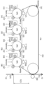
도 3은 도 1의 인쇄 엔진의 구체적인 구성의 일 실시 예를 나타내는 도면이다.3 is a view showing an embodiment of a specific configuration of the print engine of FIG. 1.
도 3을 참조하면, 인쇄 엔진(200)은 탠덤(tandem) 방식으로 동작한다. 여기서 탠덤 방식이란 고속의 출력을 위하여 색상별 감광 드럼이 개별적으로 화상을 형성하는 작업을 수행하는 칼라 인쇄 방식이다.Referring to FIG. 3, the print engine 200 operates in a tandem manner. Here, the tandem method is a color printing method in which a photosensitive drum for each color forms an image individually for high-speed output.
감광 드럼(210, 220, 230, 240)에는 정전잠상이 형성된다. 감광 드럼(210, 220, 230, 240)은 그 형태에 따라서 OPC, 감광 드럼, 감광 벨트 등으로 지칭될 수 있다.An electrostatic latent image is formed on the
대전기(217, 227, 237, 247)는 감광 드럼(210, 220, 230, 240) 표면을 균일한 전위로 대전시킨다. 대전기(217, 227, 237, 247)는 코로나 대전기, 대전 롤러, 대전 브러쉬 등의 형태로 구현될 수 있다.The
노광기(미도시)는 인쇄할 화상 정보에 따라 감광 드럼(210, 220, 230, 240)의 표면 전위를 변화시킴으로써 감광 드럼(210, 220, 230, 240)의 표면에 정전 잠상을 형성시킨다. 일 예로서, 노광기(미도시)는 인쇄할 화상 정보에 따라 변조된 광을 감광 드럼(210, 220, 230, 240)에 조사함으로써 정전 잠상을 형성할 수 있다. 이러한 노광기는 페이지 동기 신호, 수평 동기 신호에 따라 동작하며, 산출된 주주사 오프셋 값 및 부주사 오프셋 값에 따라 노광기의 동작 시점이 조장될 수 있다.An exposure machine (not shown) forms an electrostatic latent image on the surface of the
현상기는 그 내부에 현상제를 수용하며, 정전잠상에 현상제를 공급하여 정전 잠상을 가시적인 화상으로 현상시킨다. 현상기는 현상제를 정전 잠상으로 공급하는 현상 롤러현상기(213, 223, 233, 243)를 포함할 수 있다. 예를 들어, 현상제는 현상 롤러현상기(213, 223, 233, 243)와 감광 드럼(210, 220, 230, 240) 사이에 형성되는 현상 전계에 의하여 현상 롤러현상기(213, 223, 233, 243)로부터 감광 드럼(210, 220, 230, 240)에 형성된 정전 잠상으로 공급될 수 있다.The developer accommodates the developer therein, and supplies the developer to the latent electrostatic image to develop the latent electrostatic image into a visible image. The developing machine may include developing
감광 드럼(210, 220, 230, 240)에 형성된 가시적인 화상은 중간 전사 벨트(250)로 1차 전사된다. 구체적으로, 색상별 전사기(215, 225, 235, 245)에 의해서 각 감광 드럼(210, 220, 230, 240)에 형성된 화상은 중간 전사 벨트(250)로 전사될 수 있다. 그리고 중간 전사 벨트(250)에 전사된 화상은 전사기(260)에 의하여 인쇄용지에 전사될 수 있다.The visible images formed on the
그리고 정착기(미도시)에 의하여 인쇄용지상에 화상은 정착된다. 이와 같은 일련의 과정에 의하여 인쇄 작업이 완료된다.And the image is fixed on the printing paper by a fixing machine (not shown). The print job is completed by such a series of processes.
이와 같은 과정을 페이지 단위로 수행함에 따라 복수의 페이지가 인쇄된다.As this process is performed in units of pages, a plurality of pages are printed.
복수의 페이지 인쇄 과정 중에서 용지 이송 경로 상의 인쇄용지들 사이의 간격을 지간이라고 지칭하고, 이러한 지간에 대응되는 중간 전사 벨트 영역 상에 공간을 지간 구간이라고 이하에서는 지칭한다.The interval between printing papers on the paper transfer path among the plurality of page printing processes is referred to as a span, and the space on the intermediate transfer belt area corresponding to the span is referred to as a span.
본 실시 예에서는 이러한 지간 구간에서 칼라 레지스트레이션을 위한 기설정된 패턴을 형성한다. 한편, 중간 전사 벨트에 형성되는 패턴은 인쇄용지에 전사되지 않기 때문에, 중간 전사 벨트(250)의 일 측에 배치된 클리닝 부재(251)를 이용하여 클리닝할 수 있다.In the present embodiment, a predetermined pattern for color registration is formed in such a section. Meanwhile, since the pattern formed on the intermediate transfer belt is not transferred to the printing paper, it can be cleaned using the cleaning
이하에서는 하나의 페이지 단위 내에서 화상 이미지와 패턴 이미지를 동시에 형성하는 동작을 도 4를 참조하여 설명한다.Hereinafter, an operation of simultaneously forming an image image and a pattern image within one page unit will be described with reference to FIG. 4.
도 4는 본 개시의 이미지 프로세서의 구성의 일 실시 예를 나타내는 블럭도이다.4 is a block diagram showing an embodiment of the configuration of the image processor of the present disclosure.
도 4를 참조하면, 이미지 프로세서(300)는 인쇄 이미지에 대한 비디오 신호를 생성하여 출력할 수 있다. 이러한 이미지 프로세서(300)는 상술한 프로세서(120)의 구성 일부일 수 있으며, 프로세서(120)와 구분된 별도의 구성일 수도 있다.Referring to FIG. 4, the image processor 300 may generate and output a video signal for a printed image. The image processor 300 may be a part of the above-described configuration of the
이미지 프로세서(300)는 SFR 블럭(310), DMA 블럭(320), 버퍼 블럭(330), 이미지 처리 블럭(340), 비디오 처리 블럭(350)으로 구성될 수 있다.The image processor 300 may include an
SFR(Special Function Register) 블럭(310)은 화상형성장치(100)의 인쇄할 이미지에 대한 정보를 저장하는 레지스터이다. 여기서 이미지에 대한 정보는 화상 이미지의 위치와 해상도, 출력할 화상의 폭, 길이, 좌우 여백 값, 농도 등이 있을 수 있다. 이러한 인쇄할 이미지에 대한 정보는 페이지 동기 신호의 입력 전에 설정된다.The SFR (Special Function Register) block 310 is a register that stores information about an image to be printed by the image forming apparatus 100. Here, the information on the image may include the location and resolution of the image, the width, length, left and right margin values, and density of the image to be output. The information about the image to be printed is set before the page synchronization signal is input.
본 실시 예에 따른 SFR 블럭(310)은 렌더링된 이미지(즉, 화상 이미지)에 대한 정보뿐만 아니라, 패턴 이미지에 대한 정보도 동시에 저장할 수 있다. 이에 따라 패턴 이미지에 대한 정보를 저장하기 위하여, 렌더링된 이미지에 대한 완료를 기다릴 필요가 없다. 또한, 반대로 다음 페이지의 렌더링 이미지에 대한 정보를 저장하기 위하여 패턴 이미지의 인쇄 완료를 기다릴 필요가 없다.The
DMA 블럭(320)은 메모리(130)에 저장된 화상데이터를 DMA(Direct Memory Access)방식으로 가져오는 기능 블럭이다.The
버퍼 블럭(330)은 DMA 블럭(320)에서 가져온 화상 데이터를 임시 저장하고, 화상 데이터를 색상별로 구분하여 각 이미지 처리 블럭(340-1, 340-2, 340-3, 340-4)에 출력하는 블럭이다.The
이미지 처리 블럭(340-1, 340-2, 340-3, 340-4) 각각은 화상 데이터에 대한 이미지 처리를 수행하는 기능 블럭이다. 예를 들어, SFR 블럭에 기초하여 농도 보정을 수행할 수 있다.Each of the image processing blocks 340-1, 340-2, 340-3, and 340-4 is a functional block that performs image processing on image data. For example, concentration correction may be performed based on the SFR block.
비디오 처리 블럭(350-1, 350-2, 350-3, 350-4)은 이미지 처리 블럭(340-1, 340-2, 340-3, 340-4)에서 출력된 데이터를 비디오 신호로 변환한다. 구체적으로, 비디오 처리 블럭(350-1, 350-2, 350-3, 350-4)은 수평 동기 신호(HSYNC)에 따라 라인별 비디오 신호를 생성하여 출력할 수 있다.The video processing blocks 350-1, 350-2, 350-3, and 350-4 convert data output from the image processing blocks 340-1, 340-2, 340-3, and 340-4 into video signals. do. Specifically, the video processing blocks 350-1, 350-2, 350-3, and 350-4 may generate and output video signals for each line according to the horizontal synchronization signal HSYNC.
이와 같이 비디오 처리 블럭(350-1, 350-2, 350-3, 350-4)은 수평 동기 신호에 따라 비디오 신호를 출력하는바, 주주사 방향에 대한 오프셋은 수평 동기 신호를 이용하여 보상될 수 있다.As described above, the video processing blocks 350-1, 350-2, 350-3, and 350-4 output a video signal according to the horizontal synchronization signal, and the offset with respect to the main scanning direction can be compensated using the horizontal synchronization signal. have.
그리고 부주사 방향에 대한 오프셋은 페이지 동기 신호를 통하여 보상할 수 있다. 이하에서는 페이지 동기 신호를 생성하는 신호 생성기에 대해서 설명한다.In addition, the offset with respect to the sub-scanning direction may be compensated through a page synchronization signal. Hereinafter, a signal generator for generating a page synchronization signal will be described.
도 5는 본 개시의 신호 생성기의 구성의 일 실시 예를 나타내는 블럭도이다.5 is a block diagram showing an embodiment of the configuration of the signal generator of the present disclosure.
도 5를 참조하면, 신호 생성기(400)는 페이지 동기 신호를 생성한다. 이러한 신호 생성기(400)는 수평 신호 카운터(410), 제어값 생성기(420), 제1 신호 생성기(430), 제2 신호 생성기(440), 선택기(450)로 구성될 수 있다.Referring to FIG. 5, the
수평 신호 카운터(410)는 수평 동기 신호를 수신하고, 수신된 수평 동기 신호의 개수를 카운터 한다. 카운터 값은 제1 신호 생성기(430), 제2 신호 생성기(440) 각각에 제공될 수 있다.The
제어값 생성기(420)는 부주사 방향에 대한 오프셋 정보 등을 저장하고, 저장된 정보를 다른 구성에 제공할 수 있다.The
제1 신호 생성기(430)는 제1 페이지 동기 신호를 생성할 수 있다. 구체적으로, 제1 신호 생성기(430)는 수평 신호 카운터(410)에서 제공한 값 및 제2 신호 생성기(440)에서 생성한 제2 페이지 동기 신호 이후에 산출된 오프셋 값에 기초하여 제1 페이지 동기 신호를 생성할 수 있다.The
제2 신호 생성기(440)는 제2 페이지 동기 신호를 생성할 수 있다. 구체적으로, 제2 신호 생성기(440)는 수평 신호 카운터(410)에서 제공한 값 및 제1 신호 생성기(430)에서 생성한 제1 페이지 동기 신호 이후에 산출된 오프셋 값에 기초하여 제2 페이지 동기 신호를 생성할 수 있다.The
선택기(450)는 홀수번째에서는 제1 신호 생성기에서 생성한 동기 신호를 페이지 동기 신호로 출력하고 짝수번째에서는 제2 신호 생성기에서 생성한 동기 신호를 페이지 동기 신호로 출력할 수 있다.The
이와 같이 신호 생성기가 복수의 신호 생성기를 이용하여 페이지 동기 신호를 생성하는 이유에 대해서는 도 11을 참조하여 후술한다.The reason why the signal generator generates the page synchronization signal using the plurality of signal generators will be described later with reference to FIG. 11.
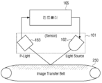
도 6은 도 2의 레지스트레이션 장치의 구성의 일 실시 예를 나타내는 블럭도이다.6 is a block diagram showing an embodiment of the configuration of the registration device of FIG. 2.
도 6을 참조하면, 레지스트레이션 장치(160)는 레지스트레이션 센서(161) 및 컨트롤러(165)를 포함할 수 있다.Referring to FIG. 6, the
레지스트레이션 센서(161)는 발광부(162) 및 수광부(163)를 포함하며, 발광부(162)는 컨트롤러(165)에서 제공되는 제어 신호에 따라 일정한 레벨로 중간전사벨트(250)에 광을 발광하고, 수광부(163)는 발광부(162)에서 발광된 광 중 중간전사벨트(250)에서 반사된 광을 감지할 수 있다. 여기서 발광부(162)는 LED로 구현될 수 있다.The
컨트롤러(165)는 레지스트레이션 센서의 발광량을 조정할 수 있다. 그리고 컨트롤러(165)는 수광부(163)에서 감지된 신호 값에 기초하여 중간 전사 벨트(250)에 형성된 기설정된 패턴을 인식하고, 그 결과로서 색상별 오프셋 값을 산출할 수 있다.The
이하에서는 도 7 내지 도 9를 참조하여 칼라 레지스트레이션 동작을 설명한다.Hereinafter, the color registration operation will be described with reference to FIGS. 7 to 9.
도 7 내지 도 9는 본 개시의 일 실시 예에 따라 형성되는 패턴을 설명하기 위한 도면이다.7 to 9 are views for explaining a pattern formed according to an embodiment of the present disclosure.
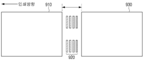
구체적으로, 도 7은 기설정된 패턴의 위치를 설명하기 위한 도면이고, 도 8은 중간 전사 벨트의 지간 구간에 형성된 기설정된 패턴을 도시한 도면이고, 도 9는 도 8를 측면에서 도시한 도면이다.Specifically, FIG. 7 is a view for explaining the position of a preset pattern, FIG. 8 is a view showing a preset pattern formed in a span section of an intermediate transfer belt, and FIG. 9 is a view showing FIG. 8 from the side .
도 7 내지 도 9를 참조하면, 첫번째 페이지(910)와 두번째 페이지(930)에 지간이 배치된다. 본 개시에서는 지간에 대응되는 중간 전사 벨트 영역의 지간 구간에 기설정된 패턴을 형성한다.Referring to FIGS. 7 to 9, a space is disposed on the
기설정된 패턴(920)은 기설정된 간격으로 배치되는 복수의 패치를 포함할 수 있다. 복수의 패치는 서로 다른 색상을 갖는 바 형태를 가질 수 있다.The
도시된 예에서는 4개의 패치만 도시되었지만, 구현시에는 5개 이상의 패치가 포함될 수 있다. 또한, 두 영역 각각에 개별적인 패치 세트가 배치되는 것을 설명하였지만, 주주사 방향으로 세 곳 이상에 패치 세트가 배치될 수 있다. 여기서 주주사 방향은 인쇄용지의 이동 방향에 수직된 방향(또는 노광기의 노광 방향)이고, 부주사 방향은 인쇄 용지의 이동 방향이다.Although only four patches are shown in the illustrated example, five or more patches may be included in the implementation. In addition, although it has been described that individual patch sets are disposed in each of the two regions, patch sets may be disposed in three or more places in the main scanning direction. Here, the main scanning direction is a direction perpendicular to the moving direction of the printing paper (or the exposure direction of the exposure machine), and the sub-scanning direction is the moving direction of the printing paper.
이와 같이 인쇄 엔진(200)에 의하여 기설정된 패턴이 중간 전사 벨트(250)에 형성되면, 회전에 의하여 중간 전사 벨트(250) 위에 패턴은 레지스트레이션 센서(161) 하부로 이동하게 된다.As described above, when a pattern preset by the print engine 200 is formed on the
따라서, 레지스트레이션 센서(161)의 아래로 기설정된 패턴이 이동하는 경우, 레지스트레이션 장치(160)는 색상별 오프셋을 산출할 수 있다.Accordingly, when a predetermined pattern moves below the
도 10은 도 4의 이미지 프로세서의 동작을 설명하기 위한 도면이다.FIG. 10 is a view for explaining the operation of the image processor of FIG. 4.
도 10을 참조하면 이미지 프로세서(300)는 페이지 싱크 신호가 입력되면, 제1 마진(예를 들어, 상단 마진)에 대응되는 시간 후에 화상 이미지에 대응되는 비디오 신호를 수평 동기 신호에 맞춰 인쇄 엔진(200)에 제공할 수 있다.Referring to FIG. 10, when the page sync signal is input, the image processor 300 adjusts the video signal corresponding to the image image to the horizontal synchronization signal after a time corresponding to the first margin (eg, the upper margin) according to the horizontal synchronization signal ( 200).
그리고 화상 이미지에 대한 비디오 신호 송출이 종료되면 페이지 완료(Page Done) 신호가 생성되는데, 이미지 프로세서(300)는 페이지 완료 신호가 입력되면, 제2 마진(예를 들어, 하단 마진)에 대응되는 시간 후에 패턴 이미지에 대응되는 비디오 신호를 수평 동기 신호에 맞춰 인쇄 엔진(200)에 제공할 수 있다.And when the video signal transmission for the image image ends, a page completion signal is generated. When the page completion signal is input to the image processor 300, the time corresponding to the second margin (eg, the bottom margin) is generated. Later, the video signal corresponding to the pattern image may be provided to the print engine 200 according to the horizontal synchronization signal.
도 11은 도 5의 신호 생성기의 동작을 설명하기 위한 도면이다.11 is a view for explaining the operation of the signal generator of FIG. 5.
레지스트레이션 장치(160)는 화상 이미지의 인쇄 과정 중에 오프셋 값을 출력할 수 있다. 예를 들어, 도 11의 좌측 시점(1110)에 제2 색상과 제3 색상 사이의 오프셋이 결정될 수 있다. 만약 결정된 오프셋이 바로 적용되는 경우, 제1과 제2 색상 사이의 오프셋 값과 제3 색상과 제4 색상 사이의 오프셋 값이 다르게 적용되어 칼라 레지스트레이션 값이 적절히 반영되지 않을 수 있다.The
따라서, 칼라 레지스트레이션 결과는 산출된 즉시 이용되는 것이 아니라 기준이 되는 페이지 싱크 신호 이후에 적용할 수 있다. 예를 들어, 도 11에서는 제1 색상에 대한 페이지 싱크 신호가 기준 페이지 싱크 신호이다. 따라서, 도 11의 우측 시점(1120)에 오프셋 값이 일괄적으로 적용되는 경우, 칼라 레지스트레이션 결과가 적절히 반영된다.Therefore, the color registration result can be applied after the calculated page sync signal, rather than being used immediately. For example, in FIG. 11, a page sync signal for a first color is a reference page sync signal. Therefore, when the offset values are collectively applied to the
이와 같은 동작을 구현하기 위하여, 도 5에 도시된 바와 같이 복수의 신호 발생기를 이용할 수 있다.In order to implement such an operation, a plurality of signal generators may be used as shown in FIG. 5.
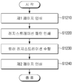
도 12는 본 개시의 일 실시 예에 따른 칼라 레지스트레이션 방법을 설명하기 위한 흐름도이다.12 is a flowchart illustrating a color registration method according to an embodiment of the present disclosure.
도 12는 참조하면, 먼저 인쇄 데이터에 포함된 제1 인쇄 이미지를 형성한다(S1210). 구체적으로, 페이지 동기 신호가 입력되면 기설정된 제1 시간 이후에 제1 인쇄 이미지에 대한 화상을 형성할 수 있다.Referring to FIG. 12, first, a first print image included in print data is formed (S1210). Specifically, when the page synchronization signal is input, an image for the first printed image may be formed after a preset first time.
그리고 제1 인쇄용지와 제2 인쇄용지 사이의 지간 구간에서 칼라 레지스트레이션을 위한 기설정된 패턴을 형성한다(S1220). 구체적으로, 제1 인쇄 이미지에 대한 인쇄 완료를 나타내는 페이지 완료 신호가 입력되면, 기설정된 제2 시간 이후에 기설정된 패턴에 대응되는 패턴 이미지를 중간 전사 벨트에 형성할 수 있다.In addition, a predetermined pattern for color registration is formed in a section between the first printing paper and the second printing paper (S1220). Specifically, when a page completion signal indicating completion of printing for the first print image is input, a pattern image corresponding to the preset pattern may be formed on the intermediate transfer belt after the preset second time.
형성된 기설정된 패턴을 이용하여 컬러 레지스트레이션을 수행한다(S1230). 구체적으로, 중간 전사 벨트에 형성된 기설정된 패턴을 이용하여 색상별 오프셋을 산출할 수 있다.Color registration is performed using the formed predetermined pattern (S1230). Specifically, the offset for each color may be calculated using a preset pattern formed on the intermediate transfer belt.
인쇄 데이터에 포함된 제2 인쇄 이미지를 형성한다(S1240). 새로운 페이지 동기 신호가 입력되면, 새로운 동기 신호 이후 제1 시간 이후에 제2 인쇄 이미지에 대한 화상을 형성할 수 있다. 여기서 새로운 동기 신호는 앞선 칼라 레지스트레이션의 결과가 반영된 신호일 수 있다. 즉, 부주사 방향에 대한 오프셋 값이 반영된 페이지 동기 신호일 수 있다.A second print image included in the print data is formed (S1240). When a new page synchronization signal is input, an image for the second printed image may be formed after a first time after the new synchronization signal. Here, the new synchronization signal may be a signal reflecting the result of the previous color registration. That is, it may be a page synchronization signal in which an offset value for a sub-scan direction is reflected.
이상과 같이 본 실시 예에 따른 칼라 레지스트레이션 방법은 일정한 주기로 컬러 레지스트레이션을 수행하는 것이 아니라, 매 페이지 단위로 칼라 레지스트레이션을 수행하는바 높은 인쇄 품질을 가질 수 있다. 또한, 지간 구간에서 컬러 레지스트레이션을 수행하는바, 컬러 레지스트레이션을 위한 별도의 시간이 요구되지 않는다.As described above, the color registration method according to the present exemplary embodiment does not perform color registration at regular intervals, but performs color registration on a page-by-page basis, and thus has high print quality. In addition, since color registration is performed in the inter-section, a separate time for color registration is not required.
도 12와 같은 칼라 레지스트레이션 방법은 도 1 또는 도 2의 구성을 가지는 화상형성장치 상에서 실행될 수 있으며, 그 밖의 다른 구성을 가지는 화상형성장치 상에서도 실행될 수 있다.The color registration method as shown in FIG. 12 may be executed on an image forming apparatus having the configuration of FIG. 1 or 2, and may also be performed on an image forming apparatus having other configurations.
한편, 상술한 칼라 레지스트레이션 방법은 프로그램으로 구현되어 화상형성장치에 제공될 수 있다. 특히, 칼라 레지스트레이션 방법을 포함하는 프로그램은 비일시적 판독 가능 매체(non-transitory computer readable medium)에 저장되어 제공될 수 있다.Meanwhile, the above-described color registration method may be implemented as a program and provided to an image forming apparatus. In particular, a program including a color registration method may be stored and provided in a non-transitory computer readable medium.
비일시적 판독 가능 매체란 레지스터, 캐쉬, 메모리 등과 같이 짧은 순간 동안 데이터를 저장하는 매체가 아니라 반영구적으로 데이터를 저장하며, 기기에 의해 판독(reading)이 가능한 매체를 의미한다. 구체적으로는, 상술한 다양한 어플리케이션 또는 프로그램들은 CD, DVD, 하드 디스크, 블루레이 디스크, USB, 메모리카드, ROM 등과 같은 비일시적 판독 가능 매체에 저장되어 제공될 수 있다.A non-transitory readable medium means a medium that stores data semi-permanently and that can be read by a device, rather than a medium that stores data for a short time, such as registers, caches, and memory. Specifically, the various applications or programs described above may be stored and provided in a non-transitory readable medium such as a CD, DVD, hard disk, Blu-ray disk, USB, memory card, ROM, and the like.
이상에서는 본 개시의 바람직한 실시예에 대해서 도시하고, 설명하였으나, 본 개시는 상술한 특정의 실시예에 한정되지 아니하며, 청구범위에서 청구하는 본 개시의 요지를 벗어남이 없이 당해 개시가 속하는 기술분야에서 통상의 지식을 가진자라면 누구든지 다양한 변형 실시가 가능한 것은 물론이고, 그와 같은 변경은 청구범위 기재의 범위 내에 있게 된다.Although the preferred embodiments of the present disclosure have been described and described above, the present disclosure is not limited to the specific embodiments described above, and it is not limited to the specific embodiments described above, without departing from the gist of the present disclosure claimed in the claims. Of course, various modifications can be made to anyone having ordinary knowledge, and such changes are within the scope of the claims.
100: 화상형성장치
110: 통신 장치
120: 프로세서
130: 메모리
140: 디스플레이
150: 입력 장치
160: 레지스트레이션 장치
200: 인쇄 장치100: image forming device 110: communication device
120: processor 130: memory
140: display 150: input device
160: registration device 200: printing device
Claims (15)
인쇄 데이터를 수신하는 통신 장치;
복수의 감광 드럼을 포함하는 인쇄 엔진; 및
상기 수신된 인쇄 데이터가 인쇄용지에 인쇄되도록 상기 인쇄 엔진을 제어하고, '용지 이송 경로 상의 인쇄용지들 사이의 지간 구간' 내에 칼라 레지스트레이션을 위한 기설정된 패턴이 형성되도록 상기 인쇄 엔진을 제어하는 프로세서;를 포함하는 화상형성장치.In the image forming apparatus,
A communication device that receives print data;
A print engine including a plurality of photosensitive drums; And
A processor that controls the print engine so that the received print data is printed on print paper, and controls the print engine such that a predetermined pattern for color registration is formed in a 'interval section between print papers on a paper transfer path'; Image forming apparatus comprising a.
상기 수신된 인쇄 데이터에 대응되는 인쇄 이미지 및 상기 기설정된 패턴에 대응되는 패턴 이미지를 비디오 신호로 변환하여 상기 인쇄 엔진에 제공하는 이미지 프로세서;를 더 포함하는 화상형성장치.According to claim 1,
And an image processor that converts a print image corresponding to the received print data and a pattern image corresponding to the preset pattern into a video signal and provides it to the print engine.
상기 이미지 프로세서는,
상기 인쇄 이미지에 대한 정보 및 상기 패턴 이미지에 대한 정보를 동시에 저장하는 레지스터를 포함하는 화상형성장치.According to claim 2,
The image processor,
An image forming apparatus including a register for simultaneously storing information on the printed image and information on the pattern image.
상기 레지스터는,
인쇄 이미지의 농도 정보 및 패턴 이미지의 농도 정보를 저장하고,
상기 이미지 프로세서는,
상기 레지스터에 저장된 인쇄 이미지의 농도 정보에 기초하여 상기 인쇄 이미지에 대한 비디오 신호를 생성하고, 이후에 상기 레지스터에 저장된 패턴 이미지의 농도 정보에 기초하여 상기 패턴 이미지에 대한 비디오 신호를 생성하는 화상형성장치.According to claim 3,
The register,
The density information of the printed image and the density information of the pattern image are stored,
The image processor,
An image forming apparatus that generates a video signal for the print image based on density information of the printed image stored in the register, and then generates a video signal for the pattern image based on density information of the pattern image stored in the register. .
상기 이미지 프로세서는,
페이지 동기 신호가 입력되면 제1 용지 마진에 대응되는 제1 시간 이후에 상기 인쇄 이미지에 대한 비디오 신호를 출력하고,
페이지 완료 신호가 입력되면 제2 용지 마진에 대응되는 제2 시간 이후에 상기 패턴 이미지에 대한 비디오 신호를 출력하는 화상형성장치.According to claim 2,
The image processor,
When a page synchronization signal is input, a video signal for the printed image is output after a first time corresponding to the first paper margin,
An image forming apparatus that outputs a video signal for the pattern image after a second time corresponding to a second paper margin when a page completion signal is input.
상기 인쇄 엔진은,
서로 다른 색상의 복수의 감광 드럼을 이용하여 중간 전사 벨트에 상기 기설정된 패턴을 인쇄하고,
상기 화상형성장치는,
상기 중간 전사 벨트에 형성된 기설정된 패턴을 인식하여 색상별 오프셋 값을 산출하는 레지스트레이션 장치;를 더 포함하는 화상형성장치.According to claim 1,
The print engine,
Printing the predetermined pattern on the intermediate transfer belt using a plurality of photosensitive drums of different colors,
The image forming apparatus,
And a registration device that recognizes a preset pattern formed on the intermediate transfer belt and calculates an offset value for each color.
부주사 방향에 대한 오프셋 값을 반영하여 페이지 동기 신호를 생성하는 신호 생성기;를 더 포함하는 화상형성장치.According to claim 1,
And a signal generator for generating a page synchronization signal by reflecting an offset value for the sub-scan direction.
상기 신호 생성기는,
제1 페이지 동기 신호를 생성하는 제1 신호 생성기;
상기 제1 페이지 동기 신호 이후에 산출된 오프셋 정보에 기초하여 제2 페이지 동기 신호를 생성하는 제2 신호 생성기; 및
상기 제1 페이지 동기 신호 및 제2 페이지 동기 신호를 교번적으로 출력하는 선택기;를 포함하고,
상기 제1 신호 생성기는,
상기 제2 페이지 동기 신호 이후에 산출된 오프셋 정보에 기초하여 제1 페이지 동기 신호를 생성하는 화상형성장치.The method of claim 7,
The signal generator,
A first signal generator for generating a first page synchronization signal;
A second signal generator that generates a second page synchronization signal based on offset information calculated after the first page synchronization signal; And
Includes a selector for alternately outputting the first page synchronization signal and the second page synchronization signal.
The first signal generator,
An image forming apparatus that generates a first page synchronization signal based on offset information calculated after the second page synchronization signal.
상기 프로세서는,
상기 지간 구간 단위로, 기설정된 제1형태를 갖는 제1 패턴 및 상기 제1형태와 상이한 제2 패턴을 교번적으로 인쇄하도록 상기 인쇄 엔진을 제어하는 화상형성장치.According to claim 1,
The processor,
An image forming apparatus that controls the print engine to alternately print a first pattern having a first shape and a second pattern different from the first shape in units of the inter-section period.
상기 제1 패턴은 주주사 방향의 오프셋을 검출하기 위한 패턴이고,
상기 제2 패턴은 부주사 방향의 오프셋을 검출하기 위한 패턴인 화상형성장치.The method of claim 9,
The first pattern is a pattern for detecting an offset in the main scanning direction,
The second pattern is an image forming apparatus that is a pattern for detecting an offset in a sub-scanning direction.
인쇄 데이터에 포함된 제1 인쇄 이미지를 형성하는 단계;
상기 제1 인쇄용지와 제2 인쇄용지 사이의 지간 구간에서 칼라 레지스트레이션을 위한 기설정된 패턴을 형성하는 단계;
상기 형성된 기설정된 패턴을 이용하여 컬러 레지스트레이션을 수행하는 단계; 및
상기 인쇄 데이터에 포함된 제2 인쇄 이미지를 형성하는 단계;를 포함하는 컬러 레지스트레이션 방법.In the color registration method in the image forming apparatus,
Forming a first print image included in the print data;
Forming a predetermined pattern for color registration in a period between the first printing paper and the second printing paper;
Performing color registration using the formed predetermined pattern; And
And forming a second print image included in the print data.
상기 기설정된 패턴을 수행하는 단계는,
상기 지간 구간 단위로, 기설정된 제1형태를 갖는 제1 패턴 및 상기 제1형태와 상이한 제2 패턴을 교번적으로 인쇄하는 컬러 레지스트레이션 방법.The method of claim 11,
Step of performing the predetermined pattern,
A color registration method for alternately printing a first pattern having a preset first shape and a second pattern different from the first shape in units of the inter-section period.
상기 제1 인쇄 이미지를 형성하는 단계는,
페이지 동기 신호가 입력되면 제1 용지 마진에 대응되는 제1 시간 이후에 상기 제1 인쇄 이미지를 형성하고,
상기 기설정된 패턴을 수행하는 단계는,
페이지 완료 신호가 입력되면 제2 용지 마진에 대응되는 제2 시간 이후에 상기 패턴 이미지에 대한 비디오 신호를 출력하는 컬러 레지스트레이션 방법.The method of claim 11,
Forming the first print image,
When the page synchronization signal is input, the first printed image is formed after a first time corresponding to the first paper margin,
Step of performing the predetermined pattern,
A color registration method of outputting a video signal for the pattern image after a second time corresponding to a second paper margin when a page completion signal is input.
상기 기설정된 패턴을 형성하는 단계는,
상기 제1 인쇄 이미지의 농도와 상기한 농도로 상기 기설정된 패턴을 형성하는 컬러 레지스트레이션 방법.The method of claim 11,
The step of forming the predetermined pattern,
A color registration method for forming the predetermined pattern with the density of the first printed image and the density.
상기 컬러 레지스트레이션을 수행하는 단계는,
상기 형성된 기설정된 패턴을 이용하여 색상별 오프셋 값을 순차적으로 산출하고,
모든 색상에 대한 오프셋 값이 산출되면 상기 산출된 오프셋 값을 일괄적으로 반영하는 컬러 레지스트레이션 방법.
The method of claim 11,
The step of performing the color registration,
The color-specific offset values are sequentially calculated using the formed predetermined pattern,
When the offset values for all colors are calculated, a color registration method that collectively reflects the calculated offset values.
Priority Applications (3)
| Application Number | Priority Date | Filing Date | Title |
|---|---|---|---|
| KR1020180135779A KR20200052616A (en) | 2018-11-07 | 2018-11-07 | Color registration in real-time |
| PCT/US2019/045915 WO2020096669A1 (en) | 2018-11-07 | 2019-08-09 | Color registration in real-time |
| US17/286,565 US11422495B2 (en) | 2018-11-07 | 2019-08-09 | Color registration in real-time |
Applications Claiming Priority (1)
| Application Number | Priority Date | Filing Date | Title |
|---|---|---|---|
| KR1020180135779A KR20200052616A (en) | 2018-11-07 | 2018-11-07 | Color registration in real-time |
Publications (1)
| Publication Number | Publication Date |
|---|---|
| KR20200052616A true KR20200052616A (en) | 2020-05-15 |
Family
ID=70612148
Family Applications (1)
| Application Number | Title | Priority Date | Filing Date |
|---|---|---|---|
| KR1020180135779A KR20200052616A (en) | 2018-11-07 | 2018-11-07 | Color registration in real-time |
Country Status (3)
| Country | Link |
|---|---|
| US (1) | US11422495B2 (en) |
| KR (1) | KR20200052616A (en) |
| WO (1) | WO2020096669A1 (en) |
Family Cites Families (10)
| Publication number | Priority date | Publication date | Assignee | Title |
|---|---|---|---|---|
| JP2003098794A (en) | 2001-09-25 | 2003-04-04 | Konica Corp | Image forming apparatus |
| KR100425310B1 (en) * | 2001-11-23 | 2004-03-30 | 삼성전자주식회사 | A color registration compensating system for electrophotographic image forming apparatus and a compensating method using that system |
| JP4534538B2 (en) | 2004-03-18 | 2010-09-01 | 富士ゼロックス株式会社 | Image forming apparatus, post-processing apparatus, calibration method, and program thereof |
| KR100677589B1 (en) * | 2005-05-24 | 2007-02-02 | 삼성전자주식회사 | Apparatus and method for controling color registration sensors |
| JP2007179005A (en) * | 2005-12-01 | 2007-07-12 | Canon Inc | Image forming apparatus |
| KR101043342B1 (en) | 2007-01-11 | 2011-06-22 | 삼성전자주식회사 | Image forming apparatus capable of controlling ACR and method for controlling ACR thereof |
| JP4502004B2 (en) * | 2007-12-26 | 2010-07-14 | セイコーエプソン株式会社 | Medium feeding method and recording apparatus in recording apparatus |
| KR102004384B1 (en) | 2013-04-03 | 2019-10-02 | 휴렛-팩커드 디벨롭먼트 컴퍼니, 엘.피. | Imaging forming apparatus and control method for the same |
| KR20150051480A (en) | 2013-11-04 | 2015-05-13 | 삼성전자주식회사 | Method for controlling condition of perforimg auto color registration and image forming apparatus using the same |
| KR20150051788A (en) | 2013-11-05 | 2015-05-13 | 삼성전자주식회사 | Image forming apparatus and the method of controlling the same |
-
2018
- 2018-11-07 KR KR1020180135779A patent/KR20200052616A/en unknown
-
2019
- 2019-08-09 US US17/286,565 patent/US11422495B2/en active Active
- 2019-08-09 WO PCT/US2019/045915 patent/WO2020096669A1/en active Application Filing
Also Published As
| Publication number | Publication date |
|---|---|
| US20210382427A1 (en) | 2021-12-09 |
| US11422495B2 (en) | 2022-08-23 |
| WO2020096669A1 (en) | 2020-05-14 |
Similar Documents
| Publication | Publication Date | Title |
|---|---|---|
| JP5390985B2 (en) | Image forming apparatus, image forming apparatus control method, and program | |
| CN106325021B (en) | Image forming apparatus, control method thereof, and non-transitory computer-readable storage medium | |
| JP2016103805A (en) | Printer, control method of the same, program and storage medium | |
| US10908524B2 (en) | Image forming apparatus and method for color registration correction | |
| JP2016147438A (en) | Image processor, printer, method for controlling image processor, method for controlling printer, program, and storage medium | |
| JP5595350B2 (en) | Image processing apparatus and image forming apparatus | |
| JP2015080104A (en) | Image reader, control method of image reader, program, and recording medium | |
| US9389565B2 (en) | Image forming apparatus, color registration method of image forming apparatus, host apparatus, control method of host apparatus, and computer readable recording medium | |
| JP5364985B2 (en) | Image forming apparatus | |
| JP5433558B2 (en) | Image forming apparatus and toner amount calculation method | |
| KR20200052616A (en) | Color registration in real-time | |
| US9897957B2 (en) | Image forming apparatus and color tone density controlling method thereof | |
| US7061514B2 (en) | Scanning system | |
| JP2016176822A (en) | Color measurement device, color measurement method, and program | |
| CN110007573A (en) | Image forming apparatus and method for correcting position | |
| US8400675B2 (en) | Image forming apparatus, image forming method, computer readable medium storing image forming program and recording medium for performing control to change the number of color materials used for at least the rim portion of the recording medium | |
| US11378905B2 (en) | Color registration by varying rotational speed of photosensitive drum | |
| JP6417910B2 (en) | Image forming apparatus, image forming apparatus control method, and image forming apparatus control program | |
| JP2015082005A (en) | Image forming apparatus, and program | |
| US11474446B2 (en) | Identifying occurrence of background based on an image density | |
| JP6844522B2 (en) | Image processing device | |
| US10162297B2 (en) | Image forming apparatus and method for controlling the same and computer-readable recording medium | |
| JP6364934B2 (en) | Writing processing apparatus, writing processing system, optical scanning apparatus, image forming apparatus, and image forming method | |
| JP6099621B2 (en) | Image forming apparatus |