JP2016103805A - Printer, control method of the same, program and storage medium - Google Patents

Printer, control method of the same, program and storage medium Download PDF

Info

Publication number
JP2016103805A
JP2016103805A JP2014242446A JP2014242446A JP2016103805A JP 2016103805 A JP2016103805 A JP 2016103805A JP 2014242446 A JP2014242446 A JP 2014242446A JP 2014242446 A JP2014242446 A JP 2014242446A JP 2016103805 A JP2016103805 A JP 2016103805A
Authority
JP
Japan
Prior art keywords
sheet
image
printing
chart
unit
Prior art date
Legal status (The legal status is an assumption and is not a legal conclusion. Google has not performed a legal analysis and makes no representation as to the accuracy of the status listed.)
Pending
Application number
JP2014242446A
Other languages
Japanese (ja)
Inventor
翔 菊池
Sho Kikuchi
翔 菊池
Current Assignee (The listed assignees may be inaccurate. Google has not performed a legal analysis and makes no representation or warranty as to the accuracy of the list.)
Canon Inc
Original Assignee
Canon Inc
Priority date (The priority date is an assumption and is not a legal conclusion. Google has not performed a legal analysis and makes no representation as to the accuracy of the date listed.)
Filing date
Publication date
Application filed by Canon Inc filed Critical Canon Inc
Priority to JP2014242446A priority Critical patent/JP2016103805A/en
Priority to US14/949,479 priority patent/US9509876B2/en
Publication of JP2016103805A publication Critical patent/JP2016103805A/en
Pending legal-status Critical Current

Links

Images

Classifications

    • HELECTRICITY
    • H04ELECTRIC COMMUNICATION TECHNIQUE
    • H04NPICTORIAL COMMUNICATION, e.g. TELEVISION
    • H04N1/00Scanning, transmission or reproduction of documents or the like, e.g. facsimile transmission; Details thereof
    • H04N1/00681Detecting the presence, position or size of a sheet or correcting its position before scanning
    • H04N1/00729Detection means
    • H04N1/00734Optical detectors
    • H04N1/00737Optical detectors using the scanning elements as detectors
    • HELECTRICITY
    • H04ELECTRIC COMMUNICATION TECHNIQUE
    • H04NPICTORIAL COMMUNICATION, e.g. TELEVISION
    • H04N1/00Scanning, transmission or reproduction of documents or the like, e.g. facsimile transmission; Details thereof
    • H04N1/00127Connection or combination of a still picture apparatus with another apparatus, e.g. for storage, processing or transmission of still picture signals or of information associated with a still picture
    • H04N1/0032Connection or combination of a still picture apparatus with another apparatus, e.g. for storage, processing or transmission of still picture signals or of information associated with a still picture with a medium handling apparatus, e.g. a sheet sorter
    • HELECTRICITY
    • H04ELECTRIC COMMUNICATION TECHNIQUE
    • H04NPICTORIAL COMMUNICATION, e.g. TELEVISION
    • H04N1/00Scanning, transmission or reproduction of documents or the like, e.g. facsimile transmission; Details thereof
    • H04N1/0035User-machine interface; Control console
    • H04N1/00352Input means
    • H04N1/00355Mark-sheet input
    • HELECTRICITY
    • H04ELECTRIC COMMUNICATION TECHNIQUE
    • H04NPICTORIAL COMMUNICATION, e.g. TELEVISION
    • H04N1/00Scanning, transmission or reproduction of documents or the like, e.g. facsimile transmission; Details thereof
    • H04N1/00681Detecting the presence, position or size of a sheet or correcting its position before scanning
    • H04N1/00742Detection methods
    • H04N1/00745Detecting the leading or trailing ends of a moving sheet
    • HELECTRICITY
    • H04ELECTRIC COMMUNICATION TECHNIQUE
    • H04NPICTORIAL COMMUNICATION, e.g. TELEVISION
    • H04N1/00Scanning, transmission or reproduction of documents or the like, e.g. facsimile transmission; Details thereof
    • H04N1/00681Detecting the presence, position or size of a sheet or correcting its position before scanning
    • H04N1/00742Detection methods
    • H04N1/00748Detecting edges, e.g. of a stationary sheet
    • HELECTRICITY
    • H04ELECTRIC COMMUNICATION TECHNIQUE
    • H04NPICTORIAL COMMUNICATION, e.g. TELEVISION
    • H04N1/00Scanning, transmission or reproduction of documents or the like, e.g. facsimile transmission; Details thereof
    • H04N1/00681Detecting the presence, position or size of a sheet or correcting its position before scanning
    • H04N1/00742Detection methods
    • H04N1/00761Detection methods using reference marks, e.g. on sheet, sheet holder or guide
    • HELECTRICITY
    • H04ELECTRIC COMMUNICATION TECHNIQUE
    • H04NPICTORIAL COMMUNICATION, e.g. TELEVISION
    • H04N1/00Scanning, transmission or reproduction of documents or the like, e.g. facsimile transmission; Details thereof
    • H04N1/00681Detecting the presence, position or size of a sheet or correcting its position before scanning
    • H04N1/00763Action taken as a result of detection
    • H04N1/00774Adjusting or controlling
    • H04N1/00779Adjusting settings, e.g. mode, feeding rate or type of paper
    • HELECTRICITY
    • H04ELECTRIC COMMUNICATION TECHNIQUE
    • H04NPICTORIAL COMMUNICATION, e.g. TELEVISION
    • H04N1/00Scanning, transmission or reproduction of documents or the like, e.g. facsimile transmission; Details thereof
    • H04N1/00962Input arrangements for operating instructions or parameters, e.g. updating internal software
    • H04N1/00968Input arrangements for operating instructions or parameters, e.g. updating internal software by scanning marks on a sheet
    • GPHYSICS
    • G03PHOTOGRAPHY; CINEMATOGRAPHY; ANALOGOUS TECHNIQUES USING WAVES OTHER THAN OPTICAL WAVES; ELECTROGRAPHY; HOLOGRAPHY
    • G03GELECTROGRAPHY; ELECTROPHOTOGRAPHY; MAGNETOGRAPHY
    • G03G15/00Apparatus for electrographic processes using a charge pattern
    • G03G15/50Machine control of apparatus for electrographic processes using a charge pattern, e.g. regulating differents parts of the machine, multimode copiers, microprocessor control
    • G03G15/5062Machine control of apparatus for electrographic processes using a charge pattern, e.g. regulating differents parts of the machine, multimode copiers, microprocessor control by measuring the characteristics of an image on the copy material
    • GPHYSICS
    • G03PHOTOGRAPHY; CINEMATOGRAPHY; ANALOGOUS TECHNIQUES USING WAVES OTHER THAN OPTICAL WAVES; ELECTROGRAPHY; HOLOGRAPHY
    • G03GELECTROGRAPHY; ELECTROPHOTOGRAPHY; MAGNETOGRAPHY
    • G03G15/00Apparatus for electrographic processes using a charge pattern
    • G03G15/50Machine control of apparatus for electrographic processes using a charge pattern, e.g. regulating differents parts of the machine, multimode copiers, microprocessor control
    • G03G15/5095Matching the image with the size of the copy material, e.g. by calculating the magnification or selecting the adequate copy material size

Landscapes

  • Engineering & Computer Science (AREA)
  • Multimedia (AREA)
  • Signal Processing (AREA)
  • Computer Vision & Pattern Recognition (AREA)
  • Control Or Security For Electrophotography (AREA)
  • Facsimiles In General (AREA)
  • Accessory Devices And Overall Control Thereof (AREA)
  • Record Information Processing For Printing (AREA)

Abstract

PROBLEM TO BE SOLVED: To solve the problem in which the significant change in the density difference between the foundation of a sheet on which a mark is printed for alignment of an image and the outside of the sheet in a case where, for example, a halation occurs on a boundary between the foundation of the sheet and the outside of the sheet at the time of scanning the image of the sheet, and the position of the mark cannot be specified since the end of the sheet of the scanned image data cannot be correctly detected in such a case.SOLUTION: An image is printed so as to lie on the end of a sheet, the printed image is read to generate image data, and the end of the sheet is detected from the generated image data.SELECTED DRAWING: Figure 9

Description

本発明は、シートに画像を印刷する印刷装置、印刷装置の制御方法、プログラム、及び記憶媒体に関する。   The present invention relates to a printing apparatus that prints an image on a sheet, a control method for the printing apparatus, a program, and a storage medium.

先端レジずれを確認するためのチャートとして、所定の幅を持った黒色の画像(以下、マークと呼ぶ)を少なくともチャートの端の一辺に接するように出力する画像形成装置がある。この画像形成装置は、出力されたチャートを読み取って画像データを生成し、当該画像データを画像診断装置に送信する。この画像診断装置は、受信した画像データに基づいて、チャートの端からマークのエッジまでの距離(余白部の距離)を測定する(特許文献1参照)。   There is an image forming apparatus that outputs a black image (hereinafter referred to as a mark) having a predetermined width so as to be in contact with at least one side of the end of the chart as a chart for confirming the tip registration error. The image forming apparatus reads the output chart, generates image data, and transmits the image data to the image diagnostic apparatus. This diagnostic imaging apparatus measures the distance from the edge of the chart to the edge of the mark (the distance of the margin) based on the received image data (see Patent Document 1).

特開2005−176045号公報JP 2005-176045 A

チャートの端及びマークのエッジの検出は、チャートの画像データの解析時に、例えば、チャートの下地とチャート外との間の濃度の変化に注目することで行われる。一方、チャートの読み取り時にチャートの下地とチャート外との境目で白飛びが発生した場合、チャートの下地とチャート外との間で濃度に有意な差が検出されないことがある。チャートの端を検出できなかった場合、仮に、マークのエッジを検出できたとしても、チャートの端からマークのエッジまでの距離を測定できない。しかしながら、上記特許文献1に記載の画像形成装置及び画像診断装置では、チャートの画像データからチャートの端を検出できない場合について何ら考慮がなされていない。   The edge of the chart and the edge of the mark are detected by, for example, paying attention to a change in density between the background of the chart and the outside of the chart when analyzing the image data of the chart. On the other hand, if whiteout occurs at the boundary between the chart background and the outside of the chart when reading the chart, a significant difference in density between the chart background and the outside of the chart may not be detected. If the edge of the chart cannot be detected, even if the edge of the mark can be detected, the distance from the edge of the chart to the edge of the mark cannot be measured. However, in the image forming apparatus and the image diagnostic apparatus described in Patent Document 1, no consideration is given to the case where the end of the chart cannot be detected from the image data of the chart.

本発明は、上記の課題に鑑みてなされたものである。例えば、シートの端に掛かるように画像を印刷することにより、当該画像を読み取って生成された画像データからシートの端を検出できる装置や方法等を提供することにある。   The present invention has been made in view of the above problems. For example, an object of the present invention is to provide an apparatus, a method, and the like that can detect an edge of a sheet from image data generated by reading the image by printing the image so as to be applied to the edge of the sheet.

上記目的を達成するために本発明の一態様に係る印刷装置は以下のような構成を備える。即ち、シートの端に掛かるように画像を印刷する印刷手段と、前記印刷手段によって印刷された前記画像を読み取って画像データを生成する読み取り手段と、前記読み取り手段によって生成された画像データからシートの端を検出する検出手段と、を有することを特徴とする。   In order to achieve the above object, a printing apparatus according to an aspect of the present invention has the following configuration. That is, a printing unit that prints an image so as to be applied to an edge of the sheet, a reading unit that reads the image printed by the printing unit to generate image data, and a sheet of the sheet from the image data generated by the reading unit. And detecting means for detecting an end.

本発明によれば、例えば、シートの端に掛かるように画像を印刷することにより、当該画像を読み取って生成された画像データからシートの端を検出することができる。   According to the present invention, for example, by printing an image so as to be applied to the edge of the sheet, the edge of the sheet can be detected from image data generated by reading the image.

本実施形態に係る印刷システムの構成を示すブロック図である。1 is a block diagram illustrating a configuration of a printing system according to an embodiment. 本実施形態に係る画像形成部の構成を示す断面図の一例である。1 is an example of a cross-sectional view illustrating a configuration of an image forming unit according to the present embodiment. 本実施形態に係るスキャナ部の構成を示す断面図の一例である。It is an example of sectional drawing which shows the structure of the scanner part which concerns on this embodiment. 本実施形態に係るテーブルの一例である。It is an example of the table which concerns on this embodiment. 本実施形態に係る画面の構成を説明するための図である。It is a figure for demonstrating the structure of the screen which concerns on this embodiment. 第1の実施形態に係る調整用チャートの模式図の一例である。It is an example of the schematic diagram of the chart for adjustment which concerns on 1st Embodiment. 第1の実施形態に係るテーブルの一例である。It is an example of the table which concerns on 1st Embodiment. 第1の実施形態に係るチャートの端の検出方法を説明するための図である。It is a figure for demonstrating the detection method of the edge of the chart which concerns on 1st Embodiment. 第1の実施形態に係る制御例を説明するためのフローチャートである。It is a flowchart for demonstrating the example of control which concerns on 1st Embodiment. 第1の実施形態に係る画面の構成を説明するための図である。It is a figure for demonstrating the structure of the screen which concerns on 1st Embodiment. 第1の実施形態に係る画面の構成を説明するための図である。It is a figure for demonstrating the structure of the screen which concerns on 1st Embodiment. 第2の実施形態に係る制御例を説明するためのフローチャートである。It is a flowchart for demonstrating the example of control which concerns on 2nd Embodiment. 第2の実施形態に係る画面の構成を説明するための図である。It is a figure for demonstrating the structure of the screen which concerns on 2nd Embodiment.

以下、本発明の実施形態について添付図面を参照して詳しく説明する。尚、以下の実施形態は特許請求の範囲に係る本発明を限定するものではなく、また本実施形態で説明されている特徴の組み合わせの全てが本発明の解決手段に必須のものとは限らない。   Hereinafter, embodiments of the present invention will be described in detail with reference to the accompanying drawings. The following embodiments do not limit the present invention according to the claims, and all the combinations of features described in the present embodiments are not necessarily essential to the solution means of the present invention. .

[第1の実施形態]
本発明の第1の実施形態に係る印刷システムの構成について図1を用いて説明する。
[First Embodiment]
The configuration of the printing system according to the first embodiment of the present invention will be described with reference to FIG.

第1の実施形態では、シートに対する印刷位置の自動調整を行う場合に、CPU114は、シートの端の一部に接するように所定のマークが形成された調整用チャートを印刷するよう画像形成部151に指示する。そして、CPU114は、当該所定のマークが印刷された調整用チャートの画像を読み取って生成された画像データを解析する。CPU114は、当該解析の結果、濃度差から当該調整用チャートの端、及び、当該所定のマークのエッジを検出する。そして、CPU114は、検出されたチャートの端、及び当該所定のマークのエッジに基づいて、印刷位置のずれ量を自動で算出し、印刷位置を調整するものである。   In the first embodiment, when the print position is automatically adjusted with respect to the sheet, the CPU 114 prints an adjustment chart on which a predetermined mark is formed so as to be in contact with a part of the edge of the sheet. To instruct. Then, the CPU 114 analyzes the image data generated by reading the image of the adjustment chart on which the predetermined mark is printed. As a result of the analysis, the CPU 114 detects the end of the adjustment chart and the edge of the predetermined mark from the density difference. Then, the CPU 114 automatically calculates the shift amount of the print position based on the detected edge of the chart and the edge of the predetermined mark, and adjusts the print position.

以下、詳細に説明する。   Details will be described below.

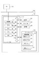
本実施形態に係る印刷システムは、印刷装置100と、外部装置の一例であるPC(コンピュータ)101とで構成される。   The printing system according to the present embodiment includes a printing apparatus 100 and a PC (computer) 101 that is an example of an external apparatus.

印刷装置100は、原稿を読み取って画像データを生成する画像読取機能と、生成した画像データに基づいて画像をシートに印刷する印刷機能(コピー機能)を備えている。また、印刷装置100は、PC101等から印刷ジョブを受信し、印刷指示を受け付けたデータに基づいて文字や画像をシートに印刷する印刷機能(PCプリント機能)を備えている。なお、印刷機能による印刷は、カラーであっても、モノクロであってもよい。   The printing apparatus 100 includes an image reading function that reads an original and generates image data, and a printing function (copy function) that prints an image on a sheet based on the generated image data. The printing apparatus 100 also includes a printing function (PC printing function) that receives a print job from the PC 101 or the like and prints characters and images on a sheet based on data for which a printing instruction has been received. Note that printing by the printing function may be in color or monochrome.

印刷装置100のコントローラ部(制御部)110は、ネットワークケーブル105を介してPC101と接続される。なお、コントローラ部110とPC101は、ネットワークケーブル105を介して接続される構成に限られない。コントローラ部110とPC101は、ローカルエリアネットワーク等のLAN(Local Area Network)を介して接続される構成であってもよい。また、コントローラ部110とPC101は、インターネット等のWAN(Wide Area Network)や、専用のプリンタケーブルを介して接続される構成であってもよい。なお、ネットワークケーブル105を介して1台のPC101が印刷装置100に接続される構成を図1に例示したが、これに限られない。ネットワークケーブル105を介して複数台のPC101が印刷装置100に接続される構成であってもよい。   A controller unit (control unit) 110 of the printing apparatus 100 is connected to the PC 101 via the network cable 105. Note that the controller unit 110 and the PC 101 are not limited to being connected via the network cable 105. The controller unit 110 and the PC 101 may be configured to be connected via a LAN (Local Area Network) such as a local area network. In addition, the controller unit 110 and the PC 101 may be configured to be connected via a WAN (Wide Area Network) such as the Internet or a dedicated printer cable. Note that the configuration in which one PC 101 is connected to the printing apparatus 100 via the network cable 105 is illustrated in FIG. 1, but is not limited thereto. A configuration in which a plurality of PCs 101 are connected to the printing apparatus 100 via the network cable 105 may be employed.

PC101は、例えば、アプリケーションソフトウェアによって画像データを生成し、生成した画像データを印刷装置100に送信する。また、PC101は、例えば、アプリケーションソフトウェアやプリンタドライバを用いて、PDL(Page Description Language)データを生成する。そして、コントローラ部110は、PC101からネットワークケーブル105を経由して送られてきたPDLデータを、ラスタライズすることにより、ビットマップデータを生成する。なお、ラスタライズする動作を実行するプログラム等は、後述するROM112又はHDD115に記憶されている。   For example, the PC 101 generates image data using application software, and transmits the generated image data to the printing apparatus 100. Further, the PC 101 generates PDL (Page Description Language) data using, for example, application software or a printer driver. Then, the controller unit 110 generates bitmap data by rasterizing the PDL data sent from the PC 101 via the network cable 105. Note that a program or the like for executing the rasterizing operation is stored in the ROM 112 or the HDD 115 described later.

なお、本実施形態では、PC101を外部装置の一例として説明するが、これに限られない。外部装置は、PDA(personal digital assistant)やスマートフォン等の携帯情報端末、ネットワーク接続機器、又は外部専用装置等であっても良い。   In the present embodiment, the PC 101 is described as an example of an external device, but is not limited thereto. The external device may be a personal digital assistant (PDA) or a mobile information terminal such as a smartphone, a network connection device, an external dedicated device, or the like.

続いて、本実施形態に係る印刷装置100のブロック図について、図1を用いて説明する。印刷装置100は、コントローラ部110、画像出力デバイスであるプリンタエンジン150、画像入力デバイスであるスキャナ部130、給送部140、及び、操作部120を有する。これらは電気的に接続されており、互いに制御コマンドやデータを送受信する。   Next, a block diagram of the printing apparatus 100 according to the present embodiment will be described with reference to FIG. The printing apparatus 100 includes a controller unit 110, a printer engine 150 that is an image output device, a scanner unit 130 that is an image input device, a feeding unit 140, and an operation unit 120. These are electrically connected and transmit / receive control commands and data to / from each other.

コントローラ部110は、印刷装置100の動作を統括的に制御すると共に、画像情報やデバイス情報の入出力制御を行う。また、コントローラ部110は、複数の機能ブロックとして、CPU114、I/O制御部111、ROM112、RAM113、及び、HDD115を有する。なお、各モジュールは、それぞれシステムバス116を介して互いに接続される。   The controller unit 110 performs overall control of the operation of the printing apparatus 100 and performs input / output control of image information and device information. The controller unit 110 includes a CPU 114, an I / O control unit 111, a ROM 112, a RAM 113, and an HDD 115 as a plurality of functional blocks. Each module is connected to each other via the system bus 116.

CPU114は、印刷装置100の全体を制御するプロセッサーである。CPU114は、ROM112に記憶された制御プログラム等に基づいて、接続中の各種デバイスとのアクセスを統括的に制御する。また、CPU114は、コントローラ部110の内部で行われる各種処理を統括的に制御する。   The CPU 114 is a processor that controls the entire printing apparatus 100. The CPU 114 comprehensively controls access to various connected devices based on a control program or the like stored in the ROM 112. In addition, the CPU 114 comprehensively controls various processes performed inside the controller unit 110.

I/O制御部111は、外部のネットワークとの通信制御を行うためのモジュールである。   The I / O control unit 111 is a module for performing communication control with an external network.

RAM113は、読み出し及び書き込み可能なメモリである。また、RAM113は、CPU114が動作するためのシステムワークメモリでもある。RAM113には、スキャナ部130やPC101等から入力された画像データや、各種プログラムや設定情報等が記憶される。   The RAM 113 is a readable / writable memory. The RAM 113 is also a system work memory for the CPU 114 to operate. The RAM 113 stores image data input from the scanner unit 130, the PC 101, etc., various programs, setting information, and the like.

ROM112は、読み出し専用のメモリである。また、ROM112は、ブートROMである。ROM112には、システムのブートプログラムが予め記憶されている。   The ROM 112 is a read-only memory. The ROM 112 is a boot ROM. The ROM 112 stores a system boot program in advance.

HDD115は、主に、コンピュータを起動・動作させるために必要な情報(システムソフトウェア)や、画像データが記憶される。   The HDD 115 mainly stores information (system software) necessary for starting and operating the computer and image data.

なお、コントローラ部110がNVRAM(不図示)を有している場合、システムソフトウェアや、画像データや、後述する操作部120を介して受け付けた設定情報等をNVRAMに記憶してもよい。   If the controller unit 110 has an NVRAM (not shown), system software, image data, setting information received via the operation unit 120 described later, and the like may be stored in the NVRAM.

RAM113又はHDD115には、印刷装置100における印刷に使用されるシートの属性情報をリスト形式で管理するためのシート管理テーブル400が記憶される。なお、シート管理テーブル400の詳細については、図4で後述する。   The RAM 113 or the HDD 115 stores a sheet management table 400 for managing sheet attribute information used for printing in the printing apparatus 100 in a list format. Details of the sheet management table 400 will be described later with reference to FIG.

ROM112又はHDD115には、CPU114により実行される、後述するフローチャートの各種処理等を実行するために必要な各種の制御プログラムが記憶されている。また、ROM112又はHDD115には、ユーザインタフェース画面(以下、UI画面)を含む操作部120の表示部(不図示)に各種のUI画面を表示させるための表示制御プログラムも記憶されている。CPU114が、ROM112又はHDD115に記憶されているプログラムを読み出して、RAM113に当該プログラムを展開することにより、本実施形態に係る各種動作を実行する。   The ROM 112 or the HDD 115 stores various control programs necessary for executing various processes in the flowcharts described later, which are executed by the CPU 114. The ROM 112 or the HDD 115 also stores a display control program for displaying various UI screens on a display unit (not shown) of the operation unit 120 including a user interface screen (hereinafter referred to as UI screen). The CPU 114 reads out a program stored in the ROM 112 or the HDD 115 and develops the program in the RAM 113, thereby executing various operations according to the present embodiment.

プリンタエンジン150は、画像形成部151と、定着ユニット155を有する。また、画像形成部151は、現像ユニット152、感光体ドラム153、及び転写ベルト154を有する。なお、画像形成部151及び定着ユニット155の詳細については、図2で後述する。   The printer engine 150 includes an image forming unit 151 and a fixing unit 155. In addition, the image forming unit 151 includes a developing unit 152, a photosensitive drum 153, and a transfer belt 154. Details of the image forming unit 151 and the fixing unit 155 will be described later with reference to FIG.

スキャナ部130は、光学センサを用いて原稿(シート)の画像をスキャンし、スキャン画像データを取得する。なお、スキャナ部130の詳細については、図3で後述する。   The scanner unit 130 scans an image of a document (sheet) using an optical sensor, and acquires scanned image data. The details of the scanner unit 130 will be described later with reference to FIG.

給送部140は、複数のシート収納部(例えば、給送カセット、給送デッキ、手差しトレイ等)からシートを給送するためのユニットである。各シート収納部は、複数種類のシートを収納することができ、また、複数枚のシートを収納することができる。シート収納部に収納されたシートのうち最上位のシートが1枚ずつ分離されて、画像形成部151に搬送される。そして、画像形成部151は、スキャナ部130やPC101等から入力された画像データに基づいて、シート収納部から給送されたシートに画像を印刷する。   The feeding unit 140 is a unit for feeding sheets from a plurality of sheet storage units (for example, a feeding cassette, a feeding deck, a manual feed tray, etc.). Each sheet storage unit can store a plurality of types of sheets and can store a plurality of sheets. Among the sheets stored in the sheet storage unit, the uppermost sheet is separated one by one and conveyed to the image forming unit 151. Then, the image forming unit 151 prints an image on a sheet fed from the sheet storage unit based on image data input from the scanner unit 130, the PC 101, or the like.

操作部120は、ユーザインタフェース部の一例に該当する。操作部120は、表示部(不図示)と、キー入力部(不図示)とを有する。また、操作部120は、表示部やキー入力部を介して、ユーザからの各種設定を受け付ける機能を有する。また、操作部120は、表示部を介して、ユーザに情報を提供する機能を有する。   The operation unit 120 corresponds to an example of a user interface unit. The operation unit 120 includes a display unit (not shown) and a key input unit (not shown). The operation unit 120 has a function of accepting various settings from the user via the display unit and the key input unit. The operation unit 120 has a function of providing information to the user via the display unit.

表示部は、LCD(Liquid Crystal Display:液晶表示部)と、LCD上に貼られた透明電極(静電容量方式でもよい)とを有するタッチパネルシートとで構成される。LCDには、操作画面が表示される他、印刷装置100の状態が表示される。キー入力部には、例えば、スキャンやコピー等の実行の開始を指示するために用いられるスタートキーや、スキャンやコピー等の稼働中の動作の中止を指示するために用いられるストップキー等がある。   The display unit includes an LCD (Liquid Crystal Display: liquid crystal display unit) and a touch panel sheet having a transparent electrode (which may be a capacitance type) attached on the LCD. On the LCD, an operation screen is displayed and the state of the printing apparatus 100 is displayed. The key input unit includes, for example, a start key used for instructing the start of execution of scanning, copying, and the like, and a stop key used for instructing cancellation of an operation in progress such as scanning and copying. .

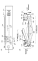
続いて、画像形成部151の構成を示す断面図の一例について、図2を用いて説明する。   Next, an example of a cross-sectional view illustrating the configuration of the image forming unit 151 will be described with reference to FIG.

画像形成部151は、コントローラ部110によって生成された画像データに従って、現像ユニット152を用いて感光体ドラム153の周囲上にトナー像を形成する。   The image forming unit 151 forms a toner image on the periphery of the photosensitive drum 153 using the developing unit 152 according to the image data generated by the controller unit 110.

なお、現像ユニット152は、感光体ドラム153に対向して配置される。現像ユニット152の内部は、垂直方向に延在する隔壁201によって現像部202と撹拌部203とに分かれている。   The developing unit 152 is disposed to face the photosensitive drum 153. The inside of the developing unit 152 is divided into a developing unit 202 and a stirring unit 203 by a partition wall 201 extending in the vertical direction.

現像部202には、矢印241の方向に回転する非磁性の現像スリーブ204が配置される。現像スリーブ204の内部には、マグネット205が固定配置される。   A nonmagnetic developing sleeve 204 that rotates in the direction of the arrow 241 is disposed in the developing unit 202. A magnet 205 is fixedly arranged inside the developing sleeve 204.

現像スリーブ204は、ブレード206によって取り出された現像剤(例えば、二成分現像剤である。磁性キャリアと非磁性トナーを含む。)を搬送する。そして、感光体ドラム153と対向する現像領域で現像剤を感光体ドラム153に供給して、感光体ドラム153上の静電潜像を現像する。なお、現像効率、即ち静電潜像へのトナーの付与率を向上させるために、現像スリーブ204には、直流電圧を交流電圧に重畳した現像バイアス電圧が印加される。   The developing sleeve 204 conveys the developer (for example, a two-component developer, including a magnetic carrier and nonmagnetic toner) taken out by the blade 206. Then, a developer is supplied to the photosensitive drum 153 in a developing area facing the photosensitive drum 153 to develop the electrostatic latent image on the photosensitive drum 153. In order to improve the developing efficiency, that is, the application rate of toner to the electrostatic latent image, a developing bias voltage in which a DC voltage is superimposed on an AC voltage is applied to the developing sleeve 204.

現像部202及び撹拌部203には、現像剤を撹拌するためのスクリュー207、208がそれぞれ配置されている。スクリュー207は、現像部202中の現像剤を撹拌し、撹拌された現像剤を搬送する。一方、スクリュー208は、トナー補給槽210のトナー排出口211から搬送スクリュー212の回転によって供給されたトナー213と、現像ユニット152内に既に存在する現像剤214とを撹拌する。そして、スクリュー208は、撹拌された現像剤を搬送し、トナー濃度を均一化する。   Screws 207 and 208 for stirring the developer are arranged in the developing unit 202 and the stirring unit 203, respectively. The screw 207 agitates the developer in the developing unit 202 and conveys the agitated developer. On the other hand, the screw 208 agitates the toner 213 supplied by the rotation of the conveying screw 212 from the toner discharge port 211 of the toner supply tank 210 and the developer 214 already present in the developing unit 152. Then, the screw 208 conveys the stirred developer to make the toner density uniform.

なお、隔壁201には、図2に示す手前側と奥側の端部において、現像部202と撹拌部203とを相互に連通させるための現像剤通路(不図示)が形成されている。現像によってトナーが消費されてトナー濃度の低下した現像部202内の現像剤は、スクリュー207、208の搬送力により、一方の現像剤通路から撹拌部203内に移動される。そして、撹拌部203内でトナー濃度が回復した現像剤は、他方の現像剤通路から現像部202内に移動されるように構成されている。   Note that a developer passage (not shown) is formed in the partition wall 201 to allow the developing unit 202 and the stirring unit 203 to communicate with each other at the front and back end portions shown in FIG. The developer in the developing unit 202 whose toner density has been reduced due to development is moved to the stirring unit 203 from one developer path by the conveying force of the screws 207 and 208. Then, the developer whose toner density has been recovered in the stirring unit 203 is configured to move into the developing unit 202 from the other developer passage.

感光体ドラム153は、矢印242の方向に回転駆動される。感光体ドラム153の周辺には、感光体ドラム153を一様に帯電する一次帯電器220、現像ユニット152、現像された可視トナー像をシートに転写する転写ユニット221、ドラムクリーナ222が感光体ドラム153の回転方向に順次配設されている。   The photosensitive drum 153 is rotationally driven in the direction of the arrow 242. Around the photosensitive drum 153, a primary charger 220 that uniformly charges the photosensitive drum 153, a developing unit 152, a transfer unit 221 that transfers the developed visible toner image to a sheet, and a drum cleaner 222 are provided on the photosensitive drum. 153 are sequentially arranged in the rotation direction.

また、感光体ドラム153の上方には像露光装置223が設けられている。像露光装置223は、半導体レーザ、ポリゴンミラー、反射鏡等からなり、コントローラ部110によってデジタル信号に変換された画像に対応するデジタル画素信号(ビデオデータ)の入力を受けて、信号に対応して変調されたレーザビームを照射する。   An image exposure device 223 is provided above the photosensitive drum 153. The image exposure device 223 includes a semiconductor laser, a polygon mirror, a reflecting mirror, etc., receives a digital pixel signal (video data) corresponding to an image converted into a digital signal by the controller unit 110, and corresponds to the signal. Irradiate a modulated laser beam.

像露光装置223は、当該レーザビームを、一次帯電器220と現像ユニット152との間で感光体ドラム153の母線方向に走査するよう照射する。そして、感光体ドラム153のドラム面は露光されて、静電潜像が形成される。その後、感光体ドラム153が回転することで、静電潜像が現像ユニット152によって可視トナー像に現像される。   The image exposure device 223 irradiates the laser beam so as to scan in the generatrix direction of the photosensitive drum 153 between the primary charger 220 and the developing unit 152. Then, the drum surface of the photosensitive drum 153 is exposed to form an electrostatic latent image. Thereafter, the photosensitive drum 153 rotates, whereby the electrostatic latent image is developed into a visible toner image by the developing unit 152.

感光体ドラム153の下部には、矢印243の方向にシートを搬送する転写ベルト154が複数のローラ間に張架されて配置される。   A transfer belt 154 that conveys a sheet in the direction of an arrow 243 is stretched between a plurality of rollers below the photosensitive drum 153.

給送部140から給送されたシートは、転写ベルト154の右側から搬送される。そして、当該シートは、転写ベルト154を挟んで対向設置される吸着帯電器230の作用により、転写ベルト154に担持されて、転写ベルト154の左側(矢印243の方向)に搬送される。そして、感光体ドラム153と転写ユニット221との間をシートが通過する際に、転写ユニット221の作用によって、感光体ドラム153上に現像された可視トナー像が当該シートに転写される。トナー像が転写されたシートは、除電用帯電器231によって転写ベルト154から分離され、定着ユニット155に搬送される。   The sheet fed from the feeding unit 140 is conveyed from the right side of the transfer belt 154. Then, the sheet is carried on the transfer belt 154 by the action of the adsorption charger 230 placed opposite to the transfer belt 154, and is conveyed to the left side of the transfer belt 154 (in the direction of the arrow 243). When the sheet passes between the photosensitive drum 153 and the transfer unit 221, the visible toner image developed on the photosensitive drum 153 is transferred to the sheet by the action of the transfer unit 221. The sheet on which the toner image has been transferred is separated from the transfer belt 154 by the charge removing unit 231 and conveyed to the fixing unit 155.

そして、定着ユニット155が備える加圧ローラ(不図示)と加熱ローラ(不図示)との間を当該シートが通過し、トナーが溶融・圧着される。これにより、シートにトナー像が定着される。なお、シートへのトナーを転写した後に感光体ドラム153上に残存するトナーは、ドラムクリーナ222により除去される。   Then, the sheet passes between a pressure roller (not shown) provided in the fixing unit 155 and a heating roller (not shown), and the toner is melted and pressed. As a result, the toner image is fixed on the sheet. Note that the toner remaining on the photosensitive drum 153 after transferring the toner to the sheet is removed by the drum cleaner 222.

続いて、スキャナ部130の構成を示す断面図の一例について、図3(A)及び図3(B)を用いて説明する。   Next, an example of a cross-sectional view illustrating a configuration of the scanner unit 130 will be described with reference to FIGS. 3A and 3B.

原稿301の画像の読み取り方法には、流し読み方式と光学系移動方式の2つの方式がある。流し読み方式では、原稿積載部(原稿トレイとも呼ぶ)340に原稿301が載置されて、自動原稿搬送装置(ADF)によって原稿301を搬送させながら、固定された光学系の位置で原稿301の画像を読み取る(ADF読みとも呼ぶ)。なお、ADFとは、Auto Document Feederのことである。一方、光学系移動方式では、プラテンガラス(原稿台)302上に原稿301が載置されて、光学系を移動させながら、原稿位置が固定された原稿301の画像を読み取る(圧板読みとも呼ぶ)。   There are two methods for reading an image of the original 301, namely a flow reading method and an optical system moving method. In the flow-reading method, a document 301 is placed on a document stacking unit (also referred to as a document tray) 340, and the document 301 is conveyed by an automatic document feeder (ADF), and the document 301 is placed at a fixed optical system position. Read an image (also called ADF reading). Note that ADF means Auto Document Feeder. On the other hand, in the optical system moving method, an original 301 is placed on a platen glass (original platen) 302, and an image of the original 301 whose original position is fixed is read while moving the optical system (also called pressure plate reading). .

本実施形態におけるスキャナ部130では、ADF読みで原稿301をスキャンする構成と、圧板読みで原稿301をスキャンする構成の両方を備えている場合について以降説明するが、これに限られない。第1の実施形態では、スキャナ部130は、ADF読みで原稿301をスキャンする構成、又は、圧板読みで原稿301をスキャンする構成のいずれかを少なくとも備えていればよい。   The scanner unit 130 according to the present embodiment will be described below with respect to a case where both the configuration for scanning the original 301 by ADF reading and the configuration for scanning the original 301 by pressure plate reading are provided, but the present invention is not limited to this. In the first embodiment, the scanner unit 130 may include at least one of a configuration for scanning the document 301 by ADF reading or a configuration for scanning the document 301 by pressure plate reading.

なお、スキャナ部130における原稿301の画像の読み取り動作(スキャン動作とも呼ぶ)の開始指示は、例えば、スキャンの実行の開始を指示するためのスタートキーがユーザによって押下されることにより行われる。もしくは、スキャン動作の開始指示は、例えば、操作部120の表示部に表示されるスタートボタンがユーザによって押下されることにより行われてもよい。   Note that an instruction to start an image reading operation (also referred to as a scanning operation) of the original 301 in the scanner unit 130 is performed, for example, when the user presses a start key for instructing the start of scanning. Alternatively, the scan operation start instruction may be performed, for example, when the user presses a start button displayed on the display unit of the operation unit 120.

まず、圧板を用いて原稿301の画像を読み取る場合について、図3(A)を用いて説明する。   First, a case where an image of the original 301 is read using a pressure plate will be described with reference to FIG.

スキャン動作の開始指示により、プラテンガラス302上に載置された原稿301の画像の読み取るために、第一ミラーユニット303と第二ミラーユニット304は、モータ312の駆動によって、ホームポジションセンサ305のある位置まで一旦戻される。そして、原稿照明ランプ306が点灯され、点灯された光は原稿301に照射される。原稿301からの反射光は、第一ミラーユニット303内の第1ミラー307と、第二ミラーユニット304内の第2ミラー308、及び、第二ミラーユニット304内の第3ミラー309を経由する。第3ミラー309からの反射光は、レンズ310を通してCCD(Charge Coupled Device)センサ311上に結像されて、光信号としてCCDセンサ311に入力される。   The first mirror unit 303 and the second mirror unit 304 have a home position sensor 305 driven by a motor 312 in order to read an image of the document 301 placed on the platen glass 302 in response to a scan operation start instruction. Once returned to position. Then, the document illumination lamp 306 is turned on, and the lit light is applied to the document 301. The reflected light from the document 301 passes through the first mirror 307 in the first mirror unit 303, the second mirror 308 in the second mirror unit 304, and the third mirror 309 in the second mirror unit 304. The reflected light from the third mirror 309 forms an image on a CCD (Charge Coupled Device) sensor 311 through the lens 310 and is input to the CCD sensor 311 as an optical signal.

なお、第二ミラーユニット304は、第一ミラーユニット303の速度(V)の半分の速度(V/2)で移動する。これにより、原稿301の全面が走査される。   The second mirror unit 304 moves at a speed (V / 2) that is half the speed (V) of the first mirror unit 303. As a result, the entire surface of the document 301 is scanned.

なお、本実施形態では、スキャナ部130が備える光学系は、原稿301からの反射光をCCDセンサ311上に結像する縮小光学系である場合について説明したが、これに限られない。スキャナ部130が備える光学系は、原稿301からの反射光をCIS(Contact Image Sensor)上に結像する等倍光学系であってもよい。   In the present embodiment, the case where the optical system included in the scanner unit 130 is a reduction optical system that forms an image of the reflected light from the document 301 on the CCD sensor 311 has been described. However, the present invention is not limited to this. The optical system provided in the scanner unit 130 may be an equal-magnification optical system that forms an image of reflected light from the original 301 on a CIS (Contact Image Sensor).

続いて、ADFを用いて原稿301の画像を読み取る場合について、図3(B)を用いて説明する。   Next, a case where an image of the original 301 is read using ADF will be described with reference to FIG.

ピックアップローラ322と給送ローラ323との間に配置されている原稿検知センサ(不図示)によって、原稿積載部340に原稿(不図示)がセットされていることを検知した場合に、ADF読みによる原稿のスキャン動作が開始される。   ADF reading is performed when it is detected by a document detection sensor (not shown) disposed between the pickup roller 322 and the feed roller 323 that a document (not shown) is set on the document stacking unit 340. The document scanning operation is started.

スキャン動作の開始指示を受け付けると、まず、原稿給送部341は、摩擦分離方式により原稿束の最上のシート(原稿)を1枚ずつ分離し、分離された原稿をレジストローラ対324まで搬送する。なお、原稿を給送する際には、ピックアップローラ322が原稿束の上に下降し、中板が上昇して原稿束を給送ローラ323に押圧することによって、原稿の給送のための予備動作に入る。その後、モータ(不図示)を駆動源として、給送ローラ323とピックアップローラ322が時計回り方向に回転することにより、原稿が搬送される。最上のシートに後続して送られようとする2枚目以降のシートは、摩擦片(不図示)により静止し、原稿積載部340に留まる。なお、原稿が分離されたことは、給送ローラ323の下流に配置された分離センサ(不図示)によって検知される。   When a scanning operation start instruction is received, first, the document feeding unit 341 separates the uppermost sheet (document) of the document bundle one by one by the friction separation method, and conveys the separated document to the registration roller pair 324. . When feeding the document, the pickup roller 322 descends onto the document bundle, the middle plate rises and presses the document bundle against the feed roller 323, so that a spare for document feeding is provided. Get into operation. Thereafter, the document is conveyed by rotating the feeding roller 323 and the pickup roller 322 clockwise using a motor (not shown) as a drive source. The second and subsequent sheets to be sent following the uppermost sheet are stopped by a friction piece (not shown) and remain on the document stacking unit 340. Note that the separation of the document is detected by a separation sensor (not shown) disposed downstream of the feeding roller 323.

その後、分離された原稿は、ガイド板(不図示)の間を通過して、レジストローラ対324まで搬送される。なお、レジストローラ対324は、原稿の先端が到達した時には停止している。そして、当該原稿は、給送ローラ323による搬送で、ループが形成されて斜行が補正されて、原稿搬送部342まで搬送される。   Thereafter, the separated document passes between guide plates (not shown) and is conveyed to the registration roller pair 324. The registration roller pair 324 is stopped when the leading edge of the document reaches. Then, the original is conveyed by the feeding roller 323, a loop is formed, skew is corrected, and the original is conveyed to the original conveying unit 342.

原稿搬送部342は、搬送ベルト325を駆動ローラ326、従動ローラ327で張架し、押圧コロ328によって搬送ベルト325をプラテンガラス302に押圧することで、搬送ベルト325を回動させる。原稿は、搬送ベルト325とプラテンガラス302の間に搬送されると、搬送ベルト325の摩擦力によりプラテンガラス302の上を通過する。   The document conveyance unit 342 rotates the conveyance belt 325 by stretching the conveyance belt 325 with a driving roller 326 and a driven roller 327 and pressing the conveyance belt 325 against the platen glass 302 with a pressing roller 328. When the document is conveyed between the conveyance belt 325 and the platen glass 302, the document passes over the platen glass 302 by the frictional force of the conveyance belt 325.

原稿給送部341から原稿搬送部342まで搬送された原稿は、搬送ベルト325によりプラテンガラス302の所定の位置まで搬送されたことに従って、駆動モータ(不図示)の停止に伴い搬送が停止される。そして、当該原稿の画像は、スキャナ部130により読み取られる。   The document transported from the document feeding unit 341 to the document transport unit 342 is transported to a predetermined position on the platen glass 302 by the transport belt 325, and the transport is stopped when the drive motor (not shown) is stopped. . Then, the image of the document is read by the scanner unit 130.

スキャナ部130による読み取りが終了した後、搬送ベルト325によって原稿が反転排送部343に搬送される。この時、反転排送部343の入口付近でシートの進行経路を規制する反転フラッパ331は、ソレノイド(不図示)の制御により、原稿を反転ローラ329まで搬送する。さらに、当該原稿は、逆時計回り方向に回転する反転ローラ329と、反転ローラ329に対向する反転コロ332によって鋏持され、搬送ローラ対330まで搬送される。   After the reading by the scanner unit 130 is completed, the document is conveyed to the reverse discharge unit 343 by the conveyance belt 325. At this time, the reverse flapper 331 that restricts the sheet traveling path near the entrance of the reverse discharge unit 343 conveys the document to the reverse roller 329 under the control of a solenoid (not shown). Further, the document is held by a reversing roller 329 that rotates counterclockwise and a reversing roller 332 that faces the reversing roller 329, and is transported to the transport roller pair 330.

原稿の後端が排出フラッパ333を抜けた地点まで到達したことに従って、排出フラッパ333は時計回り方向に回動するとともに、反転ローラ329は逆転して時計回り方向に回転する。これにより、原稿のスイッチバック搬送が開始される。このようにして、反転ローラ329の時計回り方向の回転により搬送された原稿は、原稿排出部344に排出される。ここで、後続の原稿がある場合、後続の原稿は、搬送ベルト325の回動により、先行の原稿と同様にして所定の位置まで搬送される。そして、駆動モータの停止に伴って読み取り位置で停止した当該原稿の画像は、スキャナ部130により読み取られる。このスキャン動作の実行中に、先行の原稿は、独立して動作する反転排送部343によって表裏が反転されて、原稿排出部344まで搬送される。   As the trailing edge of the document reaches the point where it exits the discharge flapper 333, the discharge flapper 333 rotates in the clockwise direction, and the reverse roller 329 rotates reversely and rotates in the clockwise direction. Thereby, the switchback conveyance of the document is started. In this way, the document conveyed by the clockwise rotation of the reverse roller 329 is discharged to the document discharge unit 344. Here, when there is a subsequent document, the subsequent document is conveyed to a predetermined position by the rotation of the conveyance belt 325 in the same manner as the preceding document. Then, the image of the document stopped at the reading position with the stop of the drive motor is read by the scanner unit 130. During the execution of this scanning operation, the preceding document is conveyed up to the document discharge unit 344 with its front and back being reversed by the reverse discharge unit 343 that operates independently.

なお、図3(B)の例では、ADFを用いて原稿301の画像を読み取るにあたって、原稿を圧板読みで読み取る位置まで搬送させ、原稿の搬送を停止してスキャンを実行する方式(光学系移動方式)で説明したが、これに限られない。例えば、スキャナ部130が原稿の搬送路上に固定された読み取りセンサを備える場合、ADFを用いる原稿301の画像の読み取り方式は、原稿を一定速度で搬送させながらスキャンを実行する方式(流し読み方式)でもよい。   In the example of FIG. 3B, when the image of the original 301 is read using the ADF, the original is conveyed to a reading position by pressure plate reading, and the original is stopped and scanning is performed (optical system movement). However, the present invention is not limited to this. For example, when the scanner unit 130 includes a reading sensor fixed on the document conveyance path, an image reading method of the document 301 using the ADF is a method in which scanning is performed while the document is conveyed at a constant speed (a flow reading method). But you can.

また、ADF読みとして、図3(B)の例では、原稿の裏面をスキャンする場合に、原稿の表面をスキャンした後、当該原稿を反転させて搬送し、続けて原稿の裏面をスキャンする方式(両面反転読みと呼ぶ)について説明したが、これに限られない。例えば、スキャナ部130が原稿の搬送路の上側と下側に2つの読み取りセンサを備える場合、流し読みを行いながら、原稿の表面と裏面を同時にスキャンする方式(両面同時読みと呼ぶ)によりADF読みを実行してもよい。   Further, in the example of FIG. 3B, as the ADF reading, in the case of scanning the back side of the document, after scanning the front side of the document, the document is reversed and conveyed, and then the back side of the document is scanned. Although described (referred to as double-sided reverse reading), it is not limited to this. For example, when the scanner unit 130 includes two reading sensors on the upper side and the lower side of the document conveyance path, ADF reading is performed by scanning the front and back sides of the document at the same time (referred to as double-sided simultaneous reading) while performing scanning reading. May be executed.

続いて、印刷装置100における印刷に使用されるシートの属性情報を管理するためのシート管理テーブル400の詳細について、図4を用いて説明する。   Next, details of the sheet management table 400 for managing attribute information of sheets used for printing in the printing apparatus 100 will be described with reference to FIG.

なお、印刷装置100において印刷に使用されるシートには、例えば、標準的に使用されるシート、プリンタメーカによって評価済みのシート、及び、標準シートや評価済みシートの属性情報がユーザによってカスタマイズされたユーザ定義のシート等がある。これら複数のシートの属性情報は、シート管理テーブル400によるリスト形式で、RAM113又はHDD115に記憶される。シート管理テーブル400に登録されている各データは、XML(Extensible Markup Language)やCSV(Comma−Separated Values)等のデジタル情報である。そして、各ソフトウェアモジュールは、RAM113又はHDD115に記憶されているシート管理テーブル400に対して読み出しと書き込みが可能である。   The sheets used for printing in the printing apparatus 100 include, for example, a standard sheet, a sheet evaluated by the printer manufacturer, and attribute information of the standard sheet and the evaluated sheet customized by the user. There are user-defined sheets and the like. The attribute information of the plurality of sheets is stored in the RAM 113 or the HDD 115 in a list format based on the sheet management table 400. Each data registered in the sheet management table 400 is digital information such as XML (Extensible Markup Language) or CSV (Comma-Separated Values). Each software module can read and write the sheet management table 400 stored in the RAM 113 or the HDD 115.

続いて、シート管理テーブル400に登録されるデータ(シートの属性情報)の詳細について以降説明する。   Next, details of data (sheet attribute information) registered in the sheet management table 400 will be described.

シート名称(411)は、印刷に使用されるシートを互いに識別するための情報である。   The sheet name (411) is information for identifying sheets used for printing from each other.

副走査方向のシート長(412)、主走査方向のシート長(413)、シートの坪量(414)、及び、シートの表面性(415)は、それぞれ、印刷に使用されるシートの物理特性である。なお、シートの表面性(415)は、シートの表面の物理特性を表すための属性であり、例えば、光沢性を上げるための表面コートが施された「コート」や、表面に凹凸のあるような「エンボス」等がある。   The sheet length (412) in the sub-scanning direction, the sheet length (413) in the main scanning direction, the basis weight (414) of the sheet, and the surface property (415) of the sheet are physical properties of the sheet used for printing, respectively. It is. The surface property (415) of the sheet is an attribute for representing the physical properties of the surface of the sheet. For example, the surface is coated with a surface coat for improving glossiness, or the surface is uneven. There is "emboss".

シートの色(416)は、シートの下地の色を表すための属性である。プレプリント紙(417)は、印刷に使用されるシートがプレプリント紙であるか否かを識別するための情報である。   The sheet color (416) is an attribute for representing the background color of the sheet. The preprint paper (417) is information for identifying whether or not the sheet used for printing is preprint paper.

印刷装置100は、理想の印刷位置に画像が印刷されるように、印刷の実行時にシートに対する印刷位置のずれを調整する。シートの表面に対する印刷位置のずれ量(420)は、シートの表面における理想の印刷位置からの位置ずれ量を表す情報である。一方、シートの裏面に対する印刷位置のずれ量(421)は、シートの裏面における理想の印刷位置からの位置ずれ量を表す情報である。   The printing apparatus 100 adjusts the deviation of the printing position with respect to the sheet when printing is performed so that the image is printed at an ideal printing position. The deviation amount (420) of the printing position with respect to the surface of the sheet is information representing the deviation amount from the ideal printing position on the surface of the sheet. On the other hand, the printing position deviation amount (421) with respect to the back surface of the sheet is information representing the positional deviation amount from the ideal printing position on the back surface of the sheet.

印刷位置のずれ量(420,421)として、例えば、シートに対する副走査方向の印刷位置のずれ量(以降、リード位置のずれ量と呼ぶ)がある。リード位置とは、シートの搬送方向の先頭におけるチャートの端を起点とした画像の印刷の開始位置のことである。なお、リード位置の初期値はゼロである。リード位置のずれ量の調整時において、像露光装置223から感光体ドラム153に照射するレーザビームの照射開始タイミングが調整される。これにより、シートの搬送方向の先頭におけるチャートの端を起点とした画像の印刷の開始位置が変更される。   Examples of the print position shift amount (420, 421) include a print position shift amount in the sub-scanning direction with respect to the sheet (hereinafter referred to as a lead position shift amount). The lead position is a start position of image printing starting from the end of the chart at the head in the sheet conveyance direction. Note that the initial value of the lead position is zero. At the time of adjusting the deviation amount of the lead position, the irradiation start timing of the laser beam irradiated from the image exposure device 223 to the photosensitive drum 153 is adjusted. Thereby, the printing start position of the image starting from the end of the chart at the head in the sheet conveying direction is changed.

また、印刷位置のずれ量(420,421)として、例えば、シートに対する主走査方向の印刷位置のずれ量(以降、サイド位置のずれ量と呼ぶ)がある。サイド位置とは、シートの搬送方向の左側におけるチャートの端を起点とした画像の印刷の開始位置のことである。なお、サイド位置の初期値はゼロである。サイド位置のずれ量の調整時において、像露光装置223から感光体ドラム153に照射するレーザビームの照射開始タイミングが調整される。これにより、シートの搬送方向の先頭におけるチャートの端を起点とした画像の印刷の開始位置が変更される。   Further, as the displacement amount (420, 421) of the printing position, for example, there is a displacement amount of the printing position in the main scanning direction with respect to the sheet (hereinafter referred to as a displacement amount of the side position). The side position is a start position of image printing starting from the end of the chart on the left side in the sheet conveyance direction. Note that the initial value of the side position is zero. At the time of adjusting the shift amount of the side position, the irradiation start timing of the laser beam applied to the photosensitive drum 153 from the image exposure device 223 is adjusted. Thereby, the printing start position of the image starting from the end of the chart at the head in the sheet conveying direction is changed.

また、印刷位置のずれ量(420,421)として、例えば、副走査方向の画像長のずれ量(理想の長さに対する倍率)と、主走査方向の画像長のずれ(理想の長さに対する倍率)がある。なお、副走査倍率、及び、主走査倍率の初期値はゼロである。副走査倍率は、転写ベルト154の駆動速度を制御することで調整される。一方、主走査倍率は、像露光装置223においてデジタル画像信号からレーザビームに変調する際のレーザビームのクロック周波数を制御することで調整される。   Further, as the displacement amount (420, 421) of the printing position, for example, the displacement amount of the image length in the sub-scanning direction (magnification with respect to the ideal length) and the displacement of the image length in the main scanning direction (magnification with respect to the ideal length) ) Note that the initial values of the sub-scanning magnification and the main scanning magnification are zero. The sub-scanning magnification is adjusted by controlling the driving speed of the transfer belt 154. On the other hand, the main scanning magnification is adjusted by controlling the clock frequency of the laser beam when the image exposure device 223 modulates the digital image signal into the laser beam.

これらの印刷位置のずれ量(420,421)は、所定のマークが印刷された調整用チャートをスキャナ部130でスキャンし、当該調整用チャート上のマークの位置を検出することで算出される。所定のマークが印刷される調整用チャートの詳細については、図6で後述する。また、調整用チャート上のマークの位置を検出する方法の詳細については、図8で後述する。   These print position deviation amounts (420, 421) are calculated by scanning the adjustment chart on which a predetermined mark is printed by the scanner unit 130 and detecting the position of the mark on the adjustment chart. Details of the adjustment chart on which the predetermined mark is printed will be described later with reference to FIG. Details of the method for detecting the position of the mark on the adjustment chart will be described later with reference to FIG.

なお、前述したように、印刷位置のずれ量(420,421)の調整は、例えば、レーザの照射タイミングを調整することにより行われる場合について説明したが、これに限られない。シートに印刷すべき画像自体を所定量シフトさせて印刷することにより、印刷位置のずれを調整してもよい。なお、印刷位置のずれ量の調整時において、ユーザは、シートに印刷する画像のシフト量を任意に指定できるようにしてもよい。   As described above, the adjustment of the printing position deviation amount (420, 421) has been described, for example, by adjusting the laser irradiation timing, but is not limited thereto. The printing position shift may be adjusted by shifting the image itself to be printed on the sheet by shifting it by a predetermined amount. It should be noted that the user may be able to arbitrarily specify the shift amount of the image to be printed on the sheet when adjusting the shift amount of the printing position.

シート管理テーブル400に登録されているシートの属性情報の編集や、シート管理テーブル400に対する新たなシートの追加登録は、図5(A)に示す編集画面500によって行うことができる。なお、編集画面500は、例えば、操作部120の表示部や、PC101のモニタ(不図示)に表示される。   Editing of the attribute information of a sheet registered in the sheet management table 400 and addition registration of a new sheet to the sheet management table 400 can be performed on the editing screen 500 shown in FIG. Note that the edit screen 500 is displayed on, for example, the display unit of the operation unit 120 or the monitor (not shown) of the PC 101.

編集画面500上でユーザによって選択されたシートは、ハイライト表示(反転表示)される。図5(A)の例では、「XYZ製紙 カラー81」のシートがハイライト表示されている。ユーザは、編集画面500上のボタン501を押下することによって、シート管理テーブル400に登録すべき新たなシートを追加することができる。また、ユーザは、編集画面500上のボタン502を押下することによって、選択されたシート(ハイライト表示されているシート)の属性情報を編集することができる。なお、ボタン501又はボタン502がユーザによって押下されたことに従って、図5(B)に示す編集画面510が呼び出される。なお、編集画面510は、例えば、操作部120の表示部や、PC101のモニタ(不図示)に表示される。   The sheet selected by the user on the editing screen 500 is highlighted (inverted display). In the example of FIG. 5A, the sheet “XYZ paper color 81” is highlighted. The user can add a new sheet to be registered in the sheet management table 400 by pressing a button 501 on the editing screen 500. The user can edit the attribute information of the selected sheet (highlighted sheet) by pressing a button 502 on the editing screen 500. Note that the edit screen 510 shown in FIG. 5B is called in response to the button 501 or the button 502 being pressed by the user. Note that the editing screen 510 is displayed on, for example, the display unit of the operation unit 120 or the monitor (not shown) of the PC 101.

ユーザは、編集画面510上で、例えば、シート名称、副走査方向のシート長、主走査方向のシート長、坪量、表面性、色、及び、プレプリント紙等に関する各データを入力することができる。なお、表面性については、印刷装置100でサポート可能な表面性のリストから選択される。また、色については、予め登録された色のリストから選択される。ユーザによって各データが入力された後、編集画面510上のボタン511が押下されることにより、その時点で入力されたデータ(シートの属性情報)が確定されて、シート管理テーブル400に登録される。   On the editing screen 510, for example, the user can input each data regarding the sheet name, the sheet length in the sub-scanning direction, the sheet length in the main scanning direction, the basis weight, the surface property, the color, the preprint paper, and the like. it can. The surface property is selected from a list of surface properties that can be supported by the printing apparatus 100. The color is selected from a list of colors registered in advance. After each data is input by the user, when the button 511 on the editing screen 510 is pressed, the data (sheet attribute information) input at that time is fixed and registered in the sheet management table 400. .

編集画面500上で、ユーザは、シート名称、副走査方向のシート長、主走査方向のシート長、坪量、表面性、及び、色に関する属性情報を入力することができる。なお、表面性は、印刷装置100でサポート可能な表面性のリストからユーザは一つを選択する。また、色は、予め登録された色のリストからユーザは任意の一つを選択することができる。また、編集画面500上では、編集するシートがプレプリント紙507であるか否かの情報をユーザは入力することができる。   On the editing screen 500, the user can input attribute information related to the sheet name, the sheet length in the sub-scanning direction, the sheet length in the main scanning direction, the basis weight, the surface property, and the color. For the surface property, the user selects one from the list of surface properties that can be supported by the printing apparatus 100. In addition, the user can select an arbitrary color from a pre-registered color list. On the editing screen 500, the user can input information on whether or not the sheet to be edited is preprinted paper 507.

編集画面500上の編集終了ボタン520が押下されると、その時点で入力されたシート属性が確定されて、シート管理テーブル400に記憶される。   When the edit end button 520 on the edit screen 500 is pressed, the sheet attribute input at that time is determined and stored in the sheet management table 400.

そして、編集画面500上のボタン503がユーザによって押下されることにより、選択されたシート(ハイライト表示されているシート)に対する印刷位置を調整するための一連の処理を実行することができる。なお、印刷位置の調整を実行する一連の処理の詳細については、図9で後述する。   Then, when the user presses a button 503 on the editing screen 500, a series of processes for adjusting the printing position for the selected sheet (the highlighted sheet) can be executed. Details of a series of processes for adjusting the printing position will be described later with reference to FIG.

続いて、印刷位置の調整に使用される調整用チャートの模式図の一例について、図6(A)及び図6(B)を用いて説明する。   Next, an example of a schematic diagram of an adjustment chart used for adjusting the printing position will be described with reference to FIGS. 6A and 6B.

まず、シートに対する印刷位置の調整のために、図6(A)に示す調整用チャート601用いる場合について説明する。   First, the case where the adjustment chart 601 shown in FIG. 6A is used for adjusting the printing position with respect to the sheet will be described.

調整用チャート601の画像データは、RAM113又はHDD115に格納されている。調整用チャート601を印刷する際に、調整用チャート601の画像データがRAM113又はHDD115から読み出されて、プリンタエンジン150に転送される。   Image data of the adjustment chart 601 is stored in the RAM 113 or the HDD 115. When printing the adjustment chart 601, the image data of the adjustment chart 601 is read from the RAM 113 or the HDD 115 and transferred to the printer engine 150.

シートに対する表面の印刷位置を調整する場合、シートの表面の特定の位置(例えば、四隅)には、マーク620が印刷される。また、シートに対する裏面の印刷位置を調整する場合、シートの裏面の特定の位置(例えば、四隅)には、マーク620が印刷される。なお、マーク620は、通常のシートに対する反射率の差が大きい色のトナー(例えば、黒色のトナー)で形成される。このように、調整用チャート601は、チャートの表面及び裏面のそれぞれに4箇所(合計8箇所)にマーク620が印刷される。   When adjusting the printing position of the surface with respect to the sheet, marks 620 are printed at specific positions (for example, four corners) on the surface of the sheet. Further, when adjusting the printing position of the back surface of the sheet, the mark 620 is printed at specific positions (for example, four corners) on the back surface of the sheet. Note that the mark 620 is formed of a color toner (for example, black toner) having a large difference in reflectance with respect to a normal sheet. As described above, the adjustment chart 601 has the marks 620 printed at four places (a total of eight places) on each of the front and back surfaces of the chart.

調整用チャート601の表面には、チャートの搬送方向を識別するための画像610、及び、チャートの表裏を識別するための画像612が印刷される。また、調整用チャート601の裏面には、チャートの搬送方向を識別するための画像611、及び、チャートの表裏を識別するための画像613が印刷される。   An image 610 for identifying the chart conveyance direction and an image 612 for identifying the front and back of the chart are printed on the surface of the adjustment chart 601. Further, an image 611 for identifying the chart conveyance direction and an image 613 for identifying the front and back of the chart are printed on the back surface of the adjustment chart 601.

即ち、両面印刷の実行時に両面画像の位置合わせを行う場合、調整用チャート601の表面には画像610及び画像612を印刷し、調整用チャート601の裏面には画像611及び画像613を印刷すればよい。一方、片面印刷の実行時に印刷位置の調整を行う場合、少なくとも調整用チャート601の表面に画像610及び画像612を印刷すればよい。   That is, when performing double-sided image alignment when performing double-sided printing, images 610 and 612 are printed on the front surface of the adjustment chart 601, and images 611 and 613 are printed on the back surface of the adjustment chart 601. Good. On the other hand, when the print position is adjusted when performing single-sided printing, the image 610 and the image 612 may be printed at least on the surface of the adjustment chart 601.

また、調整用チャート601の搬送方向を識別するための画像610及び画像611は、調整用チャート601をADF読みでスキャンする場合に印刷されていればよく、調整用チャート601を圧板読みでスキャンする場合には印刷されていなくてもよい。   The image 610 and the image 611 for identifying the conveyance direction of the adjustment chart 601 may be printed when the adjustment chart 601 is scanned by ADF reading, and the adjustment chart 601 is scanned by pressure plate reading. In some cases, it may not be printed.

なお、図6(A)に示すように画像610及び画像611は、例えば、チャートの搬送方向をユーザが識別可能な矢印である。一方、画像612及び画像613は、例えば、チャートの表裏をユーザが識別可能な文字である。   As shown in FIG. 6A, the images 610 and 611 are, for example, arrows that allow the user to identify the chart conveyance direction. On the other hand, the image 612 and the image 613 are characters that allow the user to identify the front and back of the chart, for example.

続いて、シートに対する印刷位置の調整のために、図6(B)に示す調整用チャート602を用いる場合について説明する。   Next, the case where the adjustment chart 602 shown in FIG. 6B is used for adjusting the printing position with respect to the sheet will be described.

調整用チャート602の画像データは、RAM113又はHDD115に格納されている。調整用チャート602を印刷する際に、調整用チャート602の画像データがRAM113又はHDD115から読み出されて、プリンタエンジン150に転送される。   The image data of the adjustment chart 602 is stored in the RAM 113 or the HDD 115. When the adjustment chart 602 is printed, the image data of the adjustment chart 602 is read from the RAM 113 or the HDD 115 and transferred to the printer engine 150.

シートに対する表面の印刷位置を調整する場合、シートの表面の特定の位置(例えば、四隅)には、マーク620が印刷される。また、シートに対する裏面の印刷位置を調整する場合、シートの裏面の特定の位置(例えば、四隅)には、マーク620が印刷される。なお、マーク620は、通常のシートに対する反射率の差が大きい色のトナー(例えば、黒色のトナー)で形成される。   When adjusting the printing position of the surface with respect to the sheet, marks 620 are printed at specific positions (for example, four corners) on the surface of the sheet. Further, when adjusting the printing position of the back surface of the sheet, the mark 620 is printed at specific positions (for example, four corners) on the back surface of the sheet. Note that the mark 620 is formed of a color toner (for example, black toner) having a large difference in reflectance with respect to a normal sheet.

また、調整用チャート602では、チャートの端を検出するために、所定の幅を持ったマーク630がチャートの端の一部に接するように印刷される。なお、調整用チャート602の印刷時に、転写ユニット221によってシートに転写されるトナー像(マーク630のトナー像)がシートの端に掛かるように、感光体ドラム153上にマーク630の像が形成される。   In the adjustment chart 602, in order to detect the end of the chart, a mark 630 having a predetermined width is printed so as to be in contact with a part of the end of the chart. Note that when the adjustment chart 602 is printed, an image of the mark 630 is formed on the photosensitive drum 153 so that the toner image (toner image of the mark 630) transferred to the sheet by the transfer unit 221 is applied to the end of the sheet. The

調整用チャート602に印刷されるマーク630は、所定の幅を持つ。このため、調整用チャート602の印刷時に、印刷位置のずれが仮に発生していたとしても、印刷位置のずれ量が調整可能な範囲内(例えば、6mm以内)であれば、調整用チャート602の端に掛かるようにマーク630が印刷されることになる。   The mark 630 printed on the adjustment chart 602 has a predetermined width. For this reason, even if a print position shift occurs during printing of the adjustment chart 602, if the print position shift amount is within an adjustable range (for example, within 6 mm), the adjustment chart 602 The mark 630 is printed so as to be placed on the end.

マーク630は、チャートの端の一部に接しているのであれば、図6(B)で示した大きさや形状に限定されるものではない。なお、マーク630の色は、マーク620の色に対して同一の色であってもよく、異なる色であってもよい。即ち、調整用チャート602には、通常のシートに対する反射率の差が大きい色のトナー(例えば、黒色のトナー)を用いてマーク630が印刷されている。   The mark 630 is not limited to the size and shape shown in FIG. 6B as long as the mark 630 is in contact with part of the end of the chart. Note that the color of the mark 630 may be the same as or different from the color of the mark 620. That is, on the adjustment chart 602, the mark 630 is printed using a color toner (for example, black toner) having a large difference in reflectance with respect to a normal sheet.

調整用チャート602におけるチャートの端の検出方法の詳細については、図8で後述する。   Details of the method of detecting the edge of the chart in the adjustment chart 602 will be described later with reference to FIG.

このように、調整用チャート602は、チャートの表面及び裏面のそれぞれに4箇所(合計8箇所)にマーク620が印刷されて、かつ、当該チャートの表面及び裏面のそれぞれに8箇所(合計16箇所)にマーク630が印刷される。   As described above, the adjustment chart 602 has the marks 620 printed at four places (total of 8 places) on each of the front and back sides of the chart, and 8 places (16 places in total) on the front and back sides of the chart. ) Is printed with a mark 630.

調整用チャート602の表面には、チャートの搬送方向を識別するための画像610、及び、チャートの表裏を識別するための画像612が印刷される。また、調整用チャート602の裏面には、チャートの搬送方向を識別するための画像611、及び、チャートの表裏を識別するための画像613が印刷される。   On the surface of the adjustment chart 602, an image 610 for identifying the chart conveyance direction and an image 612 for identifying the front and back of the chart are printed. Further, an image 611 for identifying the chart conveyance direction and an image 613 for identifying the front and back of the chart are printed on the back surface of the adjustment chart 602.

即ち、両面印刷の実行時に、両面画像の位置合わせを行う場合、調整用チャート602の表面には画像610及び画像612を印刷し、調整用チャート602の裏面には画像611、及び画像613を印刷すればよい。一方、片面印刷の実行時に印刷位置の調整を行う場合、少なくとも調整用チャート602の表面に画像610及び画像612を印刷すればよい。   That is, when performing double-sided printing, when aligning double-sided images, the image 610 and the image 612 are printed on the front surface of the adjustment chart 602, and the images 611 and 613 are printed on the back surface of the adjustment chart 602. do it. On the other hand, when the print position is adjusted when performing single-sided printing, the image 610 and the image 612 may be printed at least on the surface of the adjustment chart 602.

また、調整用チャート602の搬送方向を識別するための画像610及び画像611は、調整用チャート602をADF読みでスキャンする場合に印刷されていればよく、調整用チャート602を圧板読みでスキャンする場合には印刷されていなくてもよい。   The image 610 and the image 611 for identifying the conveyance direction of the adjustment chart 602 may be printed when the adjustment chart 602 is scanned by ADF reading, and the adjustment chart 602 is scanned by pressure plate reading. In some cases, it may not be printed.

なお、図6(B)に示すように画像610及び画像611は、例えば、チャートの搬送方向をユーザが識別可能な矢印である。一方、画像612及び画像613は、例えば、チャートの表裏をユーザが識別可能な文字である。   As shown in FIG. 6B, the image 610 and the image 611 are arrows that allow the user to identify the chart conveyance direction, for example. On the other hand, the image 612 and the image 613 are characters that allow the user to identify the front and back of the chart, for example.

マーク620は、理想通りの位置に印刷されている場合、チャートの端から所定の距離の位置に印刷されるように配置される。そこで、本実施形態では、シートに対する表面の印刷位置の調整を調整用チャート601で行う場合、調整用チャート601の表面に印刷されているマーク620の位置を測定することにより、シートの表面の印刷位置のずれ量が算出(又は取得)される。同様に、本実施形態では、シートに対する表面の印刷位置の調整を調整用チャート602で行う場合、調整用チャート602の表面に印刷されているマーク620の位置を測定することにより、シートの表面の印刷位置のずれ量が算出(又は取得)される。   When the mark 620 is printed at an ideal position, the mark 620 is arranged to be printed at a predetermined distance from the end of the chart. Therefore, in the present embodiment, when the adjustment of the printing position of the front surface with respect to the sheet is performed using the adjustment chart 601, the position of the mark 620 printed on the surface of the adjustment chart 601 is measured to thereby print the surface of the sheet. A positional deviation amount is calculated (or acquired). Similarly, in the present embodiment, when the adjustment of the printing position of the surface with respect to the sheet is performed using the adjustment chart 602, the position of the mark 620 printed on the surface of the adjustment chart 602 is measured, thereby A printing position shift amount is calculated (or acquired).

また、本実施形態では、シートに対する裏面の印刷位置の調整を調整用チャート601で行う場合、調整用チャート601の裏面に印刷されているマーク620の位置を測定することにより、シートの裏面の印刷位置のずれ量が算出(又は取得)される。同様に、本実施形態では、シートに対する裏面の印刷位置の調整を調整用チャート602で行う場合、調整用チャート602の裏面に印刷されているマーク620の位置を測定することにより、シートの裏面の印刷位置のずれ量が算出(又は取得)される。   In this embodiment, when the adjustment of the printing position on the back surface of the sheet is performed using the adjustment chart 601, the position of the mark 620 printed on the back surface of the adjustment chart 601 is measured to print the back surface of the sheet. A positional deviation amount is calculated (or acquired). Similarly, in this embodiment, when the adjustment of the printing position of the back surface with respect to the sheet is performed using the adjustment chart 602, the position of the mark 620 printed on the back surface of the adjustment chart 602 is measured, thereby A printing position shift amount is calculated (or acquired).

なお、調整用チャート601の表面及び裏面に印刷されている各々のマーク620の相対位置を測定することで、表面の印刷位置に対しての裏面の印刷位置のずれ量、又は、裏面の印刷位置に対しての表面の印刷位置のずれ量を算出(又は取得)してもよい。同様に、調整用チャート602の表面及び裏面に印刷されている各々のマーク620の相対位置を測定することで、表面の印刷位置に対しての裏面の印刷位置のずれ量、又は、裏面の印刷位置に対しての表面の印刷位置のずれ量を算出(又は取得)してもよい。   In addition, by measuring the relative position of each mark 620 printed on the front and back surfaces of the adjustment chart 601, the amount of deviation of the back surface print position from the front surface print position, or the back surface print position The displacement amount of the printing position on the surface with respect to may be calculated (or acquired). Similarly, by measuring the relative position of each mark 620 printed on the front surface and the back surface of the adjustment chart 602, the amount of deviation of the back surface print position from the front surface print position, or the back surface printing. You may calculate (or acquire) the deviation | shift amount of the printing position of the surface with respect to a position.

続いて、調整用チャート601、もしくは、調整用チャート602を用いて印刷位置の調整を行う場合について、図6(A)及び図6(B)を用いて以降説明する。   Subsequently, a case where the print position is adjusted using the adjustment chart 601 or the adjustment chart 602 will be described below with reference to FIGS. 6A and 6B.

調整用チャート(601,602)の表面と裏面のそれぞれのマーク620の位置を測定するために、調整用チャート(601,602)の表面における(a)〜(j)で表される部分が測定される。また、調整用チャート(601,602)の裏面における(k)〜(r)で表される部分が測定される。   In order to measure the positions of the respective marks 620 on the front and back surfaces of the adjustment chart (601, 602), the portions represented by (a) to (j) on the surface of the adjustment chart (601, 602) are measured. Is done. Moreover, the part represented by (k)-(r) in the back surface of the chart for adjustment (601, 602) is measured.

なお、(a)の部分は、調整用チャート(601,602)の副走査方向の長さであり、(b)の部分は調整用チャート(601,602)の主走査方向の長さである。なお、(a)の部分の理想的な長さは、シート管理テーブル400によって登録されている副走査方向のシート長(412)である。また、(b)の部分の理想的な長さは、シート管理テーブル400によって登録されている主走査方向のシート長(413)である。一方、(c)〜(r)の長さは、それぞれ、マーク620から直近のチャートの端までの距離である。   The part (a) is the length in the sub-scanning direction of the adjustment chart (601, 602), and the part (b) is the length in the main scanning direction of the adjustment chart (601, 602). . The ideal length of the portion (a) is the sheet length (412) in the sub-scanning direction registered by the sheet management table 400. The ideal length of the portion (b) is the sheet length (413) in the main scanning direction registered by the sheet management table 400. On the other hand, the lengths (c) to (r) are distances from the mark 620 to the edge of the most recent chart.

なお、(a)〜(r)の長さの測定方法として、手動で測定する方法と、自動で算出する方法とがある。手動で測定する方法では、ユーザが、調整用チャート(601,602)に定規を当てることにより、(a)〜(r)の長さを実測する。   In addition, there exist the method of measuring manually and the method of calculating automatically as a measuring method of the length of (a)-(r). In the manual measurement method, the user actually measures the lengths (a) to (r) by placing a ruler on the adjustment charts (601, 602).

一方、自動で算出する方法では、調整用チャート(601,602)をスキャナ部130でスキャンする。そして、CPU114は、調整用チャート(601,602)の画像を読み取って生成された画像データを解析する。CPU114は、当該解析の結果、濃度差から調整用チャート(601,602)の端、及び、マーク620のエッジ(即ち、チャートの下地とマーク620の境界)を検出する。そして、CPU114は、検出されたチャートの端、及びマーク620のエッジ812から(a)〜(r)の長さを算出する。   On the other hand, in the automatic calculation method, the adjustment chart (601, 602) is scanned by the scanner unit 130. Then, the CPU 114 analyzes the image data generated by reading the image of the adjustment chart (601, 602). As a result of the analysis, the CPU 114 detects the end of the adjustment chart (601, 602) and the edge of the mark 620 (that is, the boundary between the background of the chart and the mark 620) from the density difference. Then, the CPU 114 calculates the lengths (a) to (r) from the edge of the detected chart and the edge 812 of the mark 620.

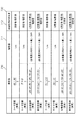
続いて、測定されたマーク620の位置に基づく印刷位置のずれ量の算出方法について、図7を用いて説明する。   Next, a method for calculating the printing position deviation based on the measured position of the mark 620 will be described with reference to FIG.

調整用チャート(601,602)の表面及び裏面における「リード位置」、「サイド位置」、「主走査倍率」、「副走査倍率」の測定値(710)、理想値(711)、及び印刷位置のずれ量(712)の各々は、図7に示すテーブル700によって定義される。なお、テーブル700は、RAM113又はHDD115に記憶される。   Measurement values (710), ideal values (711), and printing positions of “lead position”, “side position”, “main scanning magnification”, and “sub-scanning magnification” on the front and back surfaces of the adjustment chart (601, 602) Each shift amount (712) is defined by the table 700 shown in FIG. The table 700 is stored in the RAM 113 or the HDD 115.

例えば、調整用チャート(601,602)の表面における「リード位置」の測定値(710)は、テーブル700に示した数式を用いて、図6で示した(c)及び(e)の実測値から算出される。即ち、リード位置は、シートの搬送方向の先頭におけるチャートの端から対応するマーク620までの距離の平均値である。   For example, the measured value (710) of the “lead position” on the surface of the adjustment chart (601, 602) is the measured value of (c) and (e) shown in FIG. Is calculated from That is, the lead position is an average value of the distances from the end of the chart at the head in the sheet conveyance direction to the corresponding mark 620.

また、例えば、調整用チャート(601,602)の表面における「サイド位置」の測定値(710)は、テーブル700に示した数式を用いて、図6で示した(f)及び(j)の実測値から算出される。即ち、サイド位置は、シートの搬送方向の左側におけるチャートの端から対応するマーク620までの距離の平均値である。   Further, for example, the measured value (710) of the “side position” on the surface of the adjustment chart (601, 602) is calculated by using the mathematical formula shown in the table 700 of (f) and (j) shown in FIG. Calculated from measured values. That is, the side position is an average value of the distances from the end of the chart on the left side in the sheet conveyance direction to the corresponding mark 620.

また、例えば、調整用チャート(601,602)の表面における「主走査倍率」の測定値(710)は、テーブル700に示した数式を用いて、図6で示した(b)、(d)、(f)、(h)、及び(j)の実測値から算出される。即ち、主走査倍率は、主走査方向に同一走査線上に並ぶマーク620間の距離の平均値である。   Further, for example, the measurement value (710) of the “main scanning magnification” on the surface of the adjustment chart (601, 602) is shown in FIG. 6 using the formula shown in the table 700 (b), (d). , (F), (h), and (j). That is, the main scanning magnification is an average value of the distances between the marks 620 arranged on the same scanning line in the main scanning direction.

また、例えば、調整用チャート(601,602)の表面における「副走査倍率」の測定値(710)は、テーブル700に示した数式を用いて、図6で示した(a)、(c)、(e)、(g)、及び(i)の実測値から算出される。即ち、副走査倍率は、副走査方向に同一走査線上に並ぶマーク620間の距離の平均値である。   Further, for example, the measurement value (710) of the “sub-scanning magnification” on the surface of the adjustment chart (601, 602) is shown in FIG. 6 using the mathematical formula shown in the table 700 (a), (c). , (E), (g), and (i). That is, the sub-scanning magnification is an average value of distances between marks 620 arranged on the same scanning line in the sub-scanning direction.

テーブル700に示すように、「リード位置」及び「サイド位置」の理想値(711)は、それぞれ1cmである。即ち、マーク620は、理想的にはそれぞれ対応するチャートの端から1cm離れた位置に印刷されるべきである。   As shown in the table 700, the ideal values (711) of “lead position” and “side position” are each 1 cm. That is, the mark 620 should ideally be printed at a position 1 cm away from the corresponding chart edge.

また、テーブル700に示すように、「主走査倍率」の理想値(711)は、シート管理テーブル400に登録されている各々のシートにおける主走査方向のシート長から2cm減算した値である。同様に、「副走査倍率」の理想値(711)は、シート管理テーブル400に登録されている各々のシートにおける副走査方向のシート長から2cm減算した値である。   As shown in the table 700, the ideal value (711) of “main scanning magnification” is a value obtained by subtracting 2 cm from the sheet length in the main scanning direction of each sheet registered in the sheet management table 400. Similarly, the ideal value (711) of “sub-scanning magnification” is a value obtained by subtracting 2 cm from the sheet length in the sub-scanning direction of each sheet registered in the sheet management table 400.

また、テーブル700に示すように、「リード位置」、「サイド位置」、「主走査倍率」、及び「副走査倍率」の各々における印刷位置のずれ量(712)は、対応する測定値(710)及び理想値(711)を用いて算出される。   Further, as shown in the table 700, the print position deviation amount (712) in each of the “lead position”, “side position”, “main scanning magnification”, and “sub-scanning magnification” corresponds to the corresponding measured value (710). ) And the ideal value (711).

より具体的に、「リード位置」及び「サイド位置」の印刷位置のずれ量(712)は、測定値(710)から理想値(711)を減算することで算出される(単位は「mm」である)。一方、「主走査倍率」及び「副走査倍率」の印刷位置のずれ量(712)は、測定値(710)から理想値(711)を減算したものを理想値(711)で除算することで算出される(単位は「%」である)。   More specifically, the printing position deviation amount (712) of “lead position” and “side position” is calculated by subtracting the ideal value (711) from the measured value (710) (unit: “mm”). Is). On the other hand, the printing position shift amount (712) of “main scanning magnification” and “sub-scanning magnification” is obtained by dividing the measured value (710) by subtracting the ideal value (711) by the ideal value (711). Calculated (unit is “%”).

以上によって算出された印刷位置のずれ量(712)は、シートの属性情報としてシート管理テーブル400に登録される。   The printing position deviation amount (712) calculated as described above is registered in the sheet management table 400 as sheet attribute information.

前述したように、調整用チャート601を用いて印刷位置の調整を行う場合、(a)〜(r)の長さを自動で算出する方法では、調整用チャート601をスキャナ部130でスキャンする。そして、CPU114は、調整用チャート601の画像を読み取って生成された画像データを解析し、例えば、チャートの下地とチャート外との間の濃度の変化に注目する。CPU114は、当該解析の結果、濃度差から調整用チャート601の端、及び、マーク620のエッジ(即ち、チャートの下地とマーク620の境界)を検出する。そして、CPU114は、検出されたチャートの端、及びマーク620のエッジ812から(a)〜(r)の長さを算出する。   As described above, when adjusting the printing position using the adjustment chart 601, the scanner unit 130 scans the adjustment chart 601 in the method of automatically calculating the lengths (a) to (r). Then, the CPU 114 analyzes the image data generated by reading the image of the adjustment chart 601 and pays attention to, for example, a change in density between the background of the chart and the outside of the chart. As a result of the analysis, the CPU 114 detects the end of the adjustment chart 601 and the edge of the mark 620 (that is, the boundary between the background of the chart and the mark 620) from the density difference. Then, the CPU 114 calculates the lengths (a) to (r) from the edge of the detected chart and the edge 812 of the mark 620.

しかしながら、調整用チャート601の読み取り時に、チャートの下地とチャート外との境目で白飛びが発生した場合、チャートの下地とチャート外との間で濃度に有意な差が検出されないことがある。このような場合、チャートの端を検知できないため、仮に、マークのエッジを検知できたとしても、チャートの端からマークのエッジまでの距離(例えば、調整用チャート601の(c)で表される部分)を測定できない。このように、チャートの読み取り時に、チャートの下地とチャート外との境目で白飛びが発生した場合、チャートの端からマークのエッジまでの距離を算出できないため、シートに対する印刷位置の自動調整ができないことがある。   However, when the adjustment chart 601 is read, if whiteout occurs at the boundary between the background of the chart and the outside of the chart, a significant difference in density may not be detected between the background of the chart and the outside of the chart. In such a case, since the edge of the chart cannot be detected, even if the edge of the mark can be detected, the distance from the edge of the chart to the edge of the mark (for example, (c) of the adjustment chart 601) Part) cannot be measured. As described above, when whiteout occurs at the boundary between the background of the chart and the outside of the chart when reading the chart, the distance from the edge of the chart to the edge of the mark cannot be calculated, and thus the print position with respect to the sheet cannot be automatically adjusted. Sometimes.

そこで、第1の実施形態では、シートに対する印刷位置の自動調整を行う場合に、CPU114は、チャートの端の一部に接するようにマーク630が形成された調整用チャート602を印刷するよう画像形成部151に指示する。   Therefore, in the first embodiment, when performing automatic adjustment of the printing position with respect to the sheet, the CPU 114 forms an image so as to print the adjustment chart 602 in which the mark 630 is formed so as to be in contact with a part of the end of the chart. The unit 151 is instructed.

なお、調整用チャート602には、前述したとおり、通常のシートに対する反射率の差が大きい色のトナー(例えば、黒色のトナー)で、マーク630がチャートの端の一部に接するように印刷されている。マーク630がチャートの端に印刷されることにより、マーク630がチャートの端に印刷されていない場合と比べて、スキャン時に白飛びが起こりにくくなるという性質がある。   Note that, as described above, the adjustment chart 602 is printed with a color toner (for example, black toner) having a large difference in reflectance with respect to a normal sheet so that the mark 630 contacts a part of the end of the chart. ing. By printing the mark 630 on the edge of the chart, there is a property that whiteout is less likely to occur during scanning than when the mark 630 is not printed on the edge of the chart.

CPU114は、マーク630が印刷された調整用チャート602の画像を読み取って生成された画像データを解析する。CPU114は、当該解析の結果、濃度差から調整用チャート602の端、及びマーク630のエッジ(即ち、チャートの下地とマーク630の境界)を検出する。そして、CPU114は、検出されたチャートの端、及びマーク630のエッジに基づいて、印刷位置のずれ量を自動で算出し、印刷位置を調整するものである。   The CPU 114 analyzes the image data generated by reading the image of the adjustment chart 602 on which the mark 630 is printed. As a result of the analysis, the CPU 114 detects the end of the adjustment chart 602 and the edge of the mark 630 (that is, the boundary between the background of the chart and the mark 630) from the density difference. Then, the CPU 114 automatically calculates the shift amount of the print position based on the detected edge of the chart and the edge of the mark 630 and adjusts the print position.

以下、詳細に説明する。   Details will be described below.

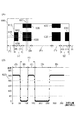
調整用チャート602をスキャナ部130でスキャンして生成された画像データ800に基づいて、調整用チャート602の端810を検出する方法について、図8(A)及び図8(B)を用いて説明する。   A method for detecting the end 810 of the adjustment chart 602 based on the image data 800 generated by scanning the adjustment chart 602 with the scanner unit 130 will be described with reference to FIGS. 8A and 8B. To do.

まず、調整用チャート602をスキャナ部130でスキャンして生成された画像データの一部を、図8(A)を用いて説明する。   First, a part of image data generated by scanning the adjustment chart 602 with the scanner unit 130 will be described with reference to FIG.

端810は、画像データ800のシートの端である。解析範囲811は、画像データ800の解析が行われる範囲である。画像データ800の解析は、画像データ800の画像端から主走査方向と副走査方向の濃度変化を画素単位で計測することで行われ、当該計測結果から端810や、マーク620が検出される。なお、計測する単位は、画素単位より微小な単位であっても、より大きな単位であってもよい。また、読み取りの間隔は、一定の間隔で行っても、間引いて行ってもよい。   An end 810 is an end of the sheet of the image data 800. The analysis range 811 is a range in which the image data 800 is analyzed. The analysis of the image data 800 is performed by measuring density changes in the main scanning direction and the sub-scanning direction from the image edge of the image data 800 in units of pixels, and the edge 810 and the mark 620 are detected from the measurement result. Note that the unit to be measured may be a smaller unit or a larger unit than the pixel unit. Further, the reading interval may be performed at regular intervals or may be thinned out.

続いて、解析範囲811における画像データ800の解析結果の一例を、図8(B)を用いて説明する。解析範囲811における画像データ800の濃度計測は、画像データ800のシートの端(画像端)から行われる。   Next, an example of the analysis result of the image data 800 in the analysis range 811 will be described with reference to FIG. The density measurement of the image data 800 in the analysis range 811 is performed from the sheet edge (image edge) of the image data 800.

まず、CPU114は、シート外(図8の区間(A)に相当)の濃度を検出する。続いて、CPU114は、マーク630に相当する箇所(図8の区間(B)に相当)の濃度を検出する。続いて、CPU114は、マーク630とマーク620との間にあるシートの下地(図8の区間(C)に相当)の濃度を検出する。続いて、CPU114は、マーク620に相当する箇所(図8の区間(D)に相当)の濃度を検出する。   First, the CPU 114 detects the density outside the sheet (corresponding to the section (A) in FIG. 8). Subsequently, the CPU 114 detects the density of the portion corresponding to the mark 630 (corresponding to the section (B) in FIG. 8). Subsequently, the CPU 114 detects the density of the background of the sheet (corresponding to the section (C) in FIG. 8) between the mark 630 and the mark 620. Subsequently, the CPU 114 detects the density of the portion corresponding to the mark 620 (corresponding to the section (D) in FIG. 8).

続いて、CPU114は、シートの下地(図8の区間(E)に相当)の濃度を再び検出する。続いて、CPU114は、マーク620に相当する箇所(図8の区間(F)に相当)の濃度を再び検出する。続いて、CPU114は、マーク630とマーク620との間にあるシートの下地(図8の区間(G)に相当)の濃度を再び検出する。続いて、CPU114は、マーク630に相当する箇所(図8の区間(H)に相当)の濃度を再び検出する。続いて、CPU114は、シート外(図8の区間(I)に相当)の濃度を再び検出する。   Subsequently, the CPU 114 detects the density of the sheet background (corresponding to the section (E) in FIG. 8) again. Subsequently, the CPU 114 detects again the density of the portion corresponding to the mark 620 (corresponding to the section (F) in FIG. 8). Subsequently, the CPU 114 detects the density of the background of the sheet (corresponding to the section (G) in FIG. 8) between the mark 630 and the mark 620 again. Subsequently, the CPU 114 detects again the density of the portion corresponding to the mark 630 (corresponding to the section (H) in FIG. 8). Subsequently, the CPU 114 detects the density outside the sheet (corresponding to the section (I) in FIG. 8) again.

そして、CPU114は、これらの測定結果に基づいて、画像データ800の区間(A)〜(I)の測定位置から範囲を算出し、マーク620とマーク630の画像の範囲(大きさ)と比較する。当該比較の結果から、CPU114は、区間(B)及び区間(H)がマーク630による濃度であると検出し、更に、区間(D)及び区間(F)がマーク620による濃度であると検出する。また、区間(C)、区間(E)、及び区間(G)がチャートの下地による濃度であると検出する。   Then, the CPU 114 calculates a range from the measurement positions in the sections (A) to (I) of the image data 800 based on these measurement results, and compares the range with the image range (size) of the mark 620 and the mark 630. . From the result of the comparison, the CPU 114 detects that the section (B) and the section (H) have the density by the mark 630, and further detects that the section (D) and the section (F) have the density by the mark 620. . In addition, the section (C), the section (E), and the section (G) are detected as the density due to the background of the chart.

そして、CPU114は、当該検出の結果から、区間(A)と区間(B)で濃度が切り替わる箇所を端810(左端)として検出し、更に、区間(C)と区間(D)で濃度が切り替わる箇所をマーク620(左マーク)のエッジ812(左端)として検出する。   Then, based on the detection result, the CPU 114 detects a position where the density is switched between the section (A) and the section (B) as an end 810 (left end), and further, the density is switched between the section (C) and the section (D). The location is detected as an edge 812 (left end) of the mark 620 (left mark).

また、CPU114は、当該検出の結果から、区間(F)と区間(G)で濃度が切り替わる箇所をマーク620(右マーク)のエッジ812(右端)として検出し、更に、区間(H)と区間(I)で濃度が切り替わる箇所を端810(右端)として検出する。   Further, the CPU 114 detects a position where the density is switched between the section (F) and the section (G) as an edge 812 (right end) of the mark 620 (right mark) based on the detection result, and further, the section (H) and the section A location where the density is switched in (I) is detected as an end 810 (right end).

そして、CPU114は、検出の結果に基づき、端810(左端)からマーク620(左マーク)のエッジ812(左端)までの距離を、調整用チャート602の(c)の長さとして自動で算出する。また、CPU114は、マーク620(右マーク)のエッジ812(右端)から端810(右端)までの距離を、調整用チャート602の(g)の長さとして自動で算出する。また、CPU114は、端810(左端)から端810(右端)までの距離を、調整用チャート602の(a)の長さとして自動で算出する。   The CPU 114 automatically calculates the distance from the end 810 (left end) to the edge 812 (left end) of the mark 620 (left mark) as the length of (c) of the adjustment chart 602 based on the detection result. . Further, the CPU 114 automatically calculates the distance from the edge 812 (right end) to the end 810 (right end) of the mark 620 (right mark) as the length of (g) in the adjustment chart 602. Further, the CPU 114 automatically calculates the distance from the end 810 (left end) to the end 810 (right end) as the length of (a) in the adjustment chart 602.

なお、調整用チャート602の(c)と(g)の長さの算出方法について上述したが、調整用チャート602の(e)と(i)、(d)と(f)、及び、(h)と(j)の長さについても、同様の方法によって算出することができる。また、調整用チャート602の(a)の長さの算出方法について上述したが、調整用チャート602の(b)の長さについても、同様の方法によって算出することができる。   In addition, although the calculation method of the length of (c) and (g) of the adjustment chart 602 has been described above, (e) and (i), (d), (f), and (h) of the adjustment chart 602 are described. ) And (j) can also be calculated by the same method. Further, although the method for calculating the length (a) of the adjustment chart 602 has been described above, the length (b) of the adjustment chart 602 can also be calculated by the same method.

このようにして、端810と、マーク620のエッジ812が検出されたことに従って、CPU114は、調整用チャート602の(a)〜(r)の長さを自動で算出することが可能となる。   In this manner, the CPU 114 can automatically calculate the lengths (a) to (r) of the adjustment chart 602 in accordance with the detection of the end 810 and the edge 812 of the mark 620.

第1の実施形態に係る印刷装置100において、印刷位置の調整を実行する一連の処理を、図9に示すフローチャートを用いて説明する。この処理は、コントローラ部110のCPU114が、ROM112又はHDD115から読み出してRAM113に展開された制御プログラムを実行することで行われる。なお、この処理は、例えば、操作部120の表示部に編集画面500が表示され、かつ、編集画面500上で任意のシートが選択された状態で開始される。   A series of processing for adjusting the printing position in the printing apparatus 100 according to the first embodiment will be described with reference to the flowchart shown in FIG. This process is performed by the CPU 114 of the controller unit 110 executing a control program read from the ROM 112 or the HDD 115 and loaded in the RAM 113. This process is started in a state where the editing screen 500 is displayed on the display unit of the operation unit 120 and an arbitrary sheet is selected on the editing screen 500, for example.

S901において、CPU114は、編集画面500上のボタン503がユーザによって押下されたか否かを判定する。CPU114は、ボタン503が押下された(即ち、YES)と判定した場合、S902に処理を進める。一方、CPU114は、NOと判定した場合、ボタン503が押下されたと判定するまで、S901の処理を繰り返す。   In step S <b> 901, the CPU 114 determines whether the button 503 on the editing screen 500 has been pressed by the user. If the CPU 114 determines that the button 503 has been pressed (ie, YES), the CPU 114 advances the process to step S902. On the other hand, if the CPU 114 determines NO, it repeats the processing of S901 until it determines that the button 503 has been pressed.

S902において、CPU114は、編集画面500上で選択されたシートに調整用チャート602を印刷するよう画像形成部151に指示する。この時、RAM113又はHDD115に格納された調整用チャート602の画像データが読み出されて、プリンタエンジン150に転送される。そして、印刷指示を受け付けた画像形成部151は、給送部140から給送されたシートに対して、調整用チャート602の画像データに基づき当該シートに調整用チャート602を印刷する。なお、調整用チャート602が印刷されたシートは、印刷装置100の機外に排出される。   In step S <b> 902, the CPU 114 instructs the image forming unit 151 to print the adjustment chart 602 on the sheet selected on the editing screen 500. At this time, the image data of the adjustment chart 602 stored in the RAM 113 or the HDD 115 is read and transferred to the printer engine 150. The image forming unit 151 that has received the print instruction prints the adjustment chart 602 on the sheet fed from the feeding unit 140 based on the image data of the adjustment chart 602. Note that the sheet on which the adjustment chart 602 is printed is discharged out of the printing apparatus 100.

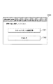
S903において、CPU114は、図10に示す選択画面1000を操作部120の表示部に表示して、S904に処理を進める。なお、選択画面1000は、印刷位置の調整方法として、スキャナを用いた自動調整(1001)、又は、手動調整(1002)のいずれかをユーザに選択させるための画面である。   In step S903, the CPU 114 displays the selection screen 1000 illustrated in FIG. 10 on the display unit of the operation unit 120, and advances the process to step S904. The selection screen 1000 is a screen for allowing the user to select either automatic adjustment using a scanner (1001) or manual adjustment (1002) as a printing position adjustment method.

S904において、CPU114は、スキャナを用いた自動調整(1001)が選択されたか否かを判定する。なお、CPU114は、選択画面1000上のボタン1001が押下された場合にYESと判定して、S905に処理を進める。一方、CPU114は、選択画面1000上のボタン1002が押下された場合にNOと判定して、S911に処理を進める。   In step S904, the CPU 114 determines whether automatic adjustment (1001) using a scanner has been selected. Note that the CPU 114 determines YES when the button 1001 on the selection screen 1000 is pressed, and advances the process to step S905. On the other hand, the CPU 114 determines NO when the button 1002 on the selection screen 1000 is pressed, and advances the process to S911.

S905において、CPU114は、S902で印刷された調整用チャート602をスキャンするようスキャナ部130に指示して、S906に処理を進める。なお、ユーザは、調整用チャート602をスキャンするために、プラテンガラス302、又は原稿積載部340上に調整用チャート602を載置する。そして、例えば、スキャンの実行の開始を指示するためのスタートキーがユーザによって押下されたことに従って、スキャナ部130に対するスキャン指示が行われる。   In step S905, the CPU 114 instructs the scanner unit 130 to scan the adjustment chart 602 printed in step S902, and advances the processing to step S906. Note that the user places the adjustment chart 602 on the platen glass 302 or the document stacking unit 340 in order to scan the adjustment chart 602. Then, for example, a scan instruction is given to the scanner unit 130 in response to the user pressing a start key for instructing the start of the scan execution.

S906において、CPU114は、調整用チャート602のスキャンにより生成された画像データ800を解析する。そして、CPU114は、チャートの端に接するマーク630を基に、調整用チャート602の端810、及びマーク620のエッジ812を検出して、S907に処理を進める。なお、画像データ800の解析処理は、図8で前述した方法によって行われる。   In step S <b> 906, the CPU 114 analyzes the image data 800 generated by scanning the adjustment chart 602. Then, the CPU 114 detects the end 810 of the adjustment chart 602 and the edge 812 of the mark 620 based on the mark 630 in contact with the end of the chart, and advances the processing to S907. The analysis process of the image data 800 is performed by the method described above with reference to FIG.

S907において、CPU114は、S906による検出処理の結果、調整用チャート602の端810、及びマーク620のエッジ812の検出に成功したか否かを判定する。CPU114は、成功した(YES)と判定した場合、S908に処理を進める。一方、CPU114は、NOと判定した場合、S909に処理を進める。なお、S907でNOと判定されるのは、例えば、調整用チャート602が印刷されたシートの下地とマーク620との濃度差が小さいために、マーク620のエッジ812の検出が正しく行われなかった場合である。   In S907, the CPU 114 determines whether or not the detection of the edge 810 of the adjustment chart 602 and the edge 812 of the mark 620 have been successfully detected as a result of the detection processing in S906. If the CPU 114 determines that the process has succeeded (YES), the process proceeds to step S908. On the other hand, if the CPU 114 determines NO, the process proceeds to S909. Note that NO is determined in S907 because, for example, the edge 812 of the mark 620 is not correctly detected because the density difference between the background of the sheet on which the adjustment chart 602 is printed and the mark 620 is small. Is the case.

S908において、CPU114は、S906で検出された端810、及びマーク620のエッジ812から、図6(B)に示した(a)〜(r)の長さを算出して、S911に処理を進める。   In S908, the CPU 114 calculates the lengths (a) to (r) shown in FIG. 6B from the end 810 detected in S906 and the edge 812 of the mark 620, and advances the process to S911. .

S909において、CPU114は、図11に示すエラー画面1100を操作部120の表示部に表示する。なお、エラー画面1100は、調整用チャートの画像データの解析に失敗したために、印刷位置の調整が実行されなかったことをユーザに通知するための画面である。S909の処理の後、図9に係る一連の処理を終了する。   In step S <b> 909, the CPU 114 displays the error screen 1100 illustrated in FIG. 11 on the display unit of the operation unit 120. The error screen 1100 is a screen for notifying the user that the adjustment of the printing position has not been executed because the analysis of the image data of the adjustment chart has failed. After the process of S909, the series of processes according to FIG.

S910において、CPU114は、手動で測定された(a)〜(r)の長さ(実測値)の入力を編集画面510上でユーザから受け付けて、S911に処理を進める。   In S910, the CPU 114 accepts an input of manually measured lengths (a) to (r) (actual values) from the user on the edit screen 510, and advances the process to S911.

S911において、CPU114は、S908で算出された(a)〜(r)の長さ、又は、S910で入力された(a)〜(r)の長さに基づいて、印刷位置のずれ量(712)を算出して、S912に処理を進める。なお、印刷位置のずれ量(712)は、図7で前述した数式を用いて算出される。   In step S911, the CPU 114 determines the amount of print position deviation (712) based on the lengths (a) to (r) calculated in step S908 or the lengths (a) to (r) input in step S910. ) And the process proceeds to S912. Note that the printing position deviation amount (712) is calculated using the mathematical formula described above with reference to FIG.

S912において、CPU114は、編集画面500上で選択されたシートに対する印刷位置のずれ量(712)として、シート管理テーブル400に登録する。なお、S912によって、選択されたシートに対する表面の印刷位置のずれ量(420)、及び裏面の印刷位置のずれ量(421)を表す情報として、例えば、リード位置、サイド位置、主走査倍率、副走査倍率等が登録される。そして、S912の処理の後、図9に係る一連の処理を終了する。   In step S <b> 912, the CPU 114 registers the print position shift amount (712) with respect to the sheet selected on the edit screen 500 in the sheet management table 400. Note that the information indicating the amount of deviation (420) of the printing position of the front surface and the amount of deviation (421) of the printing position of the back surface with respect to the selected sheet by S912 is, for example, the lead position, the side position, the main scanning magnification, Scanning magnification and the like are registered. And after the process of S912, a series of processes which concern on FIG. 9 are complete | finished.

以上が、第1の実施形態に係る印刷装置100において、印刷位置の調整を実行する一連の処理の詳細である。   The above is the details of a series of processes for adjusting the printing position in the printing apparatus 100 according to the first embodiment.

以上説明したように、第1の実施形態では、シートの端の一部に接するようにマーク630が形成された調整用チャート602を印刷した。シートの端に掛かるように画像を印刷することにより、当該画像を読み取って生成された画像データからシートの端を検出することができる。   As described above, in the first embodiment, the adjustment chart 602 in which the mark 630 is formed so as to be in contact with a part of the end of the sheet is printed. By printing an image so as to be applied to the edge of the sheet, the edge of the sheet can be detected from image data generated by reading the image.

このため、シートに対する印刷位置の自動調整を行う場合に、CPU114は、調整用チャート602のスキャンにより印刷位置のずれを自動で算出することができる。故に、ユーザは、印刷位置のずれを知るために、調整用チャート602のマーク620からチャートの端までの長さを手動で計測する手間を省くことができる。   For this reason, when performing automatic adjustment of the printing position with respect to the sheet, the CPU 114 can automatically calculate the deviation of the printing position by scanning the adjustment chart 602. Therefore, the user can save the trouble of manually measuring the length from the mark 620 of the adjustment chart 602 to the end of the chart in order to know the shift of the printing position.

[第2の実施形態]
前述した第1の実施形態では、スキャナを用いた自動調整(1001)により印刷位置のずれを調整する場合であっても、手動調整(1002)により印刷位置のずれを調整する場合であっても、調整用チャート602を印刷して使用する場合について説明した。
[Second Embodiment]
In the first embodiment described above, whether the printing position deviation is adjusted by automatic adjustment (1001) using a scanner or the printing position deviation is adjusted by manual adjustment (1002). The case where the adjustment chart 602 is printed and used has been described.

一方、手動調整(1002)を行う場合、シートの端に接するようにマーク630が印刷された調整用チャート602を使用する代わりに、調整用チャート601を使用してもよい。なぜなら、手動調整(1002)では、マーク620からチャートの端までの長さをユーザが手動で計測する際に、マーク630を参照する必要がないからである。   On the other hand, when performing manual adjustment (1002), instead of using the adjustment chart 602 on which the mark 630 is printed so as to contact the edge of the sheet, the adjustment chart 601 may be used. This is because the manual adjustment (1002) does not require the user to refer to the mark 630 when manually measuring the length from the mark 620 to the end of the chart.

スキャナを用いた自動調整(1001)を圧板読みで行う場合、例えば、プラテンガラス302上に載置された調整用チャート601の上から黒色の画像のバッキングシート(不図示)を充ててスキャンする。このようにして、スキャナを用いた自動調整(1001)を圧板読みで行う場合、シートの端に接するようにマーク630が印刷された調整用チャート602を使用する代わりに、調整用チャート601を使用してもよい。   When automatic adjustment (1001) using a scanner is performed by pressure plate reading, for example, a black image backing sheet (not shown) is applied and scanned from above the adjustment chart 601 placed on the platen glass 302. In this way, when automatic adjustment (1001) using a scanner is performed by pressure plate reading, the adjustment chart 601 is used instead of using the adjustment chart 602 on which the mark 630 is printed so as to contact the edge of the sheet. May be.

他方、スキャナを用いた自動調整(1001)をADF読みで行う場合、原稿積載部340上に載置された調整用チャート601の上から黒色の画像のバッキングシートを充ててスキャンすることができない。そのため、スキャナを用いた自動調整(1001)をADF読みで行う場合、シートの端に接するようにマーク630が印刷された調整用チャート602を使用する必要がある。   On the other hand, when the automatic adjustment (1001) using the scanner is performed by ADF reading, it is not possible to scan with a black image backing sheet from above the adjustment chart 601 placed on the document stacking unit 340. Therefore, when automatic adjustment (1001) using a scanner is performed by ADF reading, it is necessary to use an adjustment chart 602 on which a mark 630 is printed so as to be in contact with the edge of the sheet.

そこで、第2の実施形態に係る印刷装置100では、スキャナを用いた自動調整(1001)を行うよう指示された場合に、圧板読みで印刷位置の調整を実行するか、又は、ADF読みで印刷位置の調整を実行するかをユーザが任意に選択できるようにする。そして、圧板読みによって印刷位置の調整を実行するよう指示された場合には、調整用チャート601を印刷し、ADF読みによって印刷位置の調整を実行するよう指示された場合は、調整用チャート602を印刷するよう制御する。また一方で、手動調整(1002)を行うよう指示された場合に、調整用チャート601を印刷するよう制御する場合について以降説明する。   Therefore, in the printing apparatus 100 according to the second embodiment, when the automatic adjustment (1001) using the scanner is instructed, the printing position is adjusted by the pressure plate reading, or the printing is performed by the ADF reading. The user can arbitrarily select whether to perform the position adjustment. Then, when an instruction to execute the adjustment of the printing position is issued by the pressure plate reading, the adjustment chart 601 is printed. When the instruction to execute the adjustment of the printing position by the ADF reading is issued, the adjustment chart 602 is displayed. Control to print. On the other hand, a case where control is performed so that the adjustment chart 601 is printed when an instruction to perform manual adjustment (1002) is given will be described.

第2の実施形態に係る印刷装置100において、印刷位置の調整を実行する一連の処理を、図12に示すフローチャートを用いて説明する。この処理は、コントローラ部110のCPU114が、ROM112又はHDD115から読み出してRAM113に展開された制御プログラムを実行することで行われる。なお、この処理は、例えば、操作部120の表示部に編集画面500が表示され、かつ、編集画面500上で任意のシートが選択された状態で開始される。   A series of processes for adjusting the printing position in the printing apparatus 100 according to the second embodiment will be described with reference to the flowchart shown in FIG. This process is performed by the CPU 114 of the controller unit 110 executing a control program read from the ROM 112 or the HDD 115 and loaded in the RAM 113. This process is started in a state where the editing screen 500 is displayed on the display unit of the operation unit 120 and an arbitrary sheet is selected on the editing screen 500, for example.

S1201において、CPU114は、編集画面500上のボタン503がユーザによって押下されたか否かを判定する。CPU114は、ボタン503が押下された(即ち、YES)と判定した場合、S1202に処理を進める。一方、CPU114は、NOと判定した場合、ボタン503が押下されたと判定するまで、S1201の処理を繰り返す。   In step S1201, the CPU 114 determines whether the button 503 on the editing screen 500 has been pressed by the user. If the CPU 114 determines that the button 503 has been pressed (ie, YES), the CPU 114 advances the processing to S1202. On the other hand, if the CPU 114 determines NO, it repeats the processing of S1201 until it determines that the button 503 has been pressed.

S1202において、CPU114は、図10に示す選択画面1000を操作部120の表示部に表示して、S1203に処理を進める。   In S1202, the CPU 114 displays the selection screen 1000 shown in FIG. 10 on the display unit of the operation unit 120, and advances the process to S1203.

S1203において、CPU114は、スキャナを用いた自動調整(1001)が選択されたか否かを判定する。なお、CPU114は、選択画面1000上のボタン1001が押下された場合にYESと判定して、S1204に処理を進める。一方、CPU114は、選択画面1000上のボタン1002が押下された場合にNOと判定して、S1216に処理を進める。   In step S1203, the CPU 114 determines whether automatic adjustment (1001) using a scanner has been selected. Note that the CPU 114 determines YES when the button 1001 on the selection screen 1000 is pressed, and advances the process to S1204. On the other hand, the CPU 114 determines NO when the button 1002 on the selection screen 1000 is pressed, and advances the process to S1216.

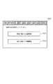
S1204において、CPU114は、図13に示す選択画面1300を操作部120の表示部に表示して、S1205に処理を進める。なお、選択画面1300は、印刷位置の調整方法として、圧板を用いた自動調整(1301)、又は、ADFを用いた自動調整(1302)のいずれかをユーザに選択させるための画面である。   In S1204, the CPU 114 displays the selection screen 1300 shown in FIG. 13 on the display unit of the operation unit 120, and advances the process to S1205. The selection screen 1300 is a screen for allowing the user to select either automatic adjustment using a pressure plate (1301) or automatic adjustment using an ADF (1302) as a printing position adjustment method.

S1205において、CPU114は、ADFを用いた自動調整(1302)が選択されたか否かを判定する。なお、CPU114は、選択画面1300上のボタン1302が押下された場合にYESと判定して、S1206に処理を進める。一方、CPU114は、選択画面1300上のボタン1301が押下された場合にNOと判定して、S1209に処理を進める。   In S1205, the CPU 114 determines whether or not automatic adjustment (1302) using ADF has been selected. Note that the CPU 114 determines YES when the button 1302 on the selection screen 1300 is pressed, and advances the process to S1206. On the other hand, the CPU 114 determines NO when the button 1301 on the selection screen 1300 is pressed, and advances the process to S1209.

S1206において、CPU114は、編集画面500上で選択されたシートに調整用チャート602を印刷するよう画像形成部151に指示する。この時、RAM113又はHDD115に格納された調整用チャート602の画像データが読み出されて、プリンタエンジン150に転送される。そして、印刷指示を受け付けた画像形成部151は、給送部140から給送されたシートに対して、調整用チャート602の画像データに基づき当該シートに調整用チャート602を印刷する。なお、調整用チャート602が印刷されたシートは、印刷装置100の機外に排出される。S1206の処理の後、S1207に処理を進める。   In step S <b> 1206, the CPU 114 instructs the image forming unit 151 to print the adjustment chart 602 on the sheet selected on the editing screen 500. At this time, the image data of the adjustment chart 602 stored in the RAM 113 or the HDD 115 is read and transferred to the printer engine 150. The image forming unit 151 that has received the print instruction prints the adjustment chart 602 on the sheet fed from the feeding unit 140 based on the image data of the adjustment chart 602. Note that the sheet on which the adjustment chart 602 is printed is discharged out of the printing apparatus 100. After the process of S1206, the process proceeds to S1207.

S1207において、CPU114は、S1206で印刷された調整用チャート602をADF読みでスキャンするようスキャナ部130に指示して、S1208に処理を進める。なお、ユーザは、調整用チャート602をスキャンするために、原稿積載部340上に調整用チャート602を載置する。そして、例えば、スキャンの実行の開始を指示するためのスタートキーがユーザによって押下されたことに従って、スキャナ部130に対するスキャン指示が行われる。   In step S1207, the CPU 114 instructs the scanner unit 130 to scan the adjustment chart 602 printed in step S1206 by ADF reading, and advances the process to step S1208. Note that the user places the adjustment chart 602 on the document stacking unit 340 in order to scan the adjustment chart 602. Then, for example, a scan instruction is given to the scanner unit 130 in response to the user pressing a start key for instructing the start of the scan execution.

S1208において、CPU114は、調整用チャート602のスキャンにより生成された画像データ800を解析する。そして、CPU114は、チャートの端に接するマーク630を基に、調整用チャート602の端810、及びマーク620のエッジ812を検出して、S1212に処理を進める。なお、画像データ800の解析処理は、図8で前述した方法によって行われる。   In step S <b> 1208, the CPU 114 analyzes the image data 800 generated by scanning the adjustment chart 602. Then, the CPU 114 detects the end 810 of the adjustment chart 602 and the edge 812 of the mark 620 based on the mark 630 in contact with the end of the chart, and advances the process to S1212. The analysis process of the image data 800 is performed by the method described above with reference to FIG.

S1209において、CPU114は、編集画面500上で選択されたシートに調整用チャート601を印刷するよう画像形成部151に指示する。この時、RAM113又はHDD115に格納された調整用チャート601の画像データが読み出されて、プリンタエンジン150に転送される。そして、印刷指示を受け付けた画像形成部151は、給送部140から給送されたシートに対して、調整用チャート601の画像データに基づき当該シートに調整用チャート601を印刷する。なお、調整用チャート601が印刷されたシートは、印刷装置100の機外に排出される。S1209の処理の後、S1210に処理を進める。   In step S <b> 1209, the CPU 114 instructs the image forming unit 151 to print the adjustment chart 601 on the sheet selected on the editing screen 500. At this time, the image data of the adjustment chart 601 stored in the RAM 113 or the HDD 115 is read and transferred to the printer engine 150. The image forming unit 151 that has received the print instruction prints the adjustment chart 601 on the sheet fed from the feeding unit 140 based on the image data of the adjustment chart 601. Note that the sheet on which the adjustment chart 601 is printed is discharged out of the printing apparatus 100. After the process of S1209, the process proceeds to S1210.

S1210において、CPU114は、S1209で印刷された調整用チャート601を圧板読みでスキャンするようスキャナ部130に指示して、S1211に処理を進める。なお、ユーザは、調整用チャート601をスキャンするために、プラテンガラス302上に調整用チャート601を載置する。そして、例えば、スキャンの実行の開始を指示するためのスタートキーがユーザによって押下されたことに従って、スキャナ部130に対するスキャン指示が行われる。   In step S1210, the CPU 114 instructs the scanner unit 130 to scan the adjustment chart 601 printed in step S1209 by pressure plate reading, and advances the process to step S1211. Note that the user places the adjustment chart 601 on the platen glass 302 in order to scan the adjustment chart 601. Then, for example, a scan instruction is given to the scanner unit 130 in response to the user pressing a start key for instructing the start of the scan execution.

S1211において、CPU114は、調整用チャート601のスキャンにより生成された画像データ(不図示)を解析する。そして、CPU114は、当該解析の結果、調整用チャート601の下地と調整用チャート601の領域外の濃度差から、調整用チャート601の端810、及びマーク620のエッジ812を検出する。なお、S1211で行われる画像データの解析処理は、図8で前述した方法と同様の方法によって説明されるため、詳細な説明を省略する。S1211の処理の後、S1212に処理を進める。   In step S1211, the CPU 114 analyzes image data (not shown) generated by scanning the adjustment chart 601. As a result of the analysis, the CPU 114 detects the end 810 of the adjustment chart 601 and the edge 812 of the mark 620 from the density difference outside the area of the adjustment chart 601 and the adjustment chart 601. Note that the image data analysis processing performed in step S1211 is described by a method similar to the method described above with reference to FIG. After the process of S1211, the process proceeds to S1212.

S1212において、CPU114は、S1208又はS1211による検出処理の結果、調整用チャート(601,602)の端810、及びマーク620のエッジ812の検出に成功したか否かを判定する。CPU114は、成功した(YES)と判定した場合、S1213に処理を進める。一方、CPU114は、NOと判定した場合、S1214に処理を進める。なお、S1212でNOと判定されるのは、例えば、調整用チャート(601,602)が印刷されたシートの下地とマーク620との濃度差が小さいために、マーク620のエッジ812の検出が正しく行われなかった場合である。   In S <b> 1212, the CPU 114 determines whether or not the detection of the edge 810 of the adjustment chart (601 and 602) and the edge 812 of the mark 620 have been successfully detected as a result of the detection processing in S <b> 1208 or S <b> 1211. If the CPU 114 determines that the process is successful (YES), the process proceeds to S1213. On the other hand, if the CPU 114 determines NO, it proceeds to S1214. Note that NO is determined in step S1212 because, for example, the density difference between the background of the sheet on which the adjustment chart (601, 602) is printed and the mark 620 is small, so that the detection of the edge 812 of the mark 620 is correct. This is the case when it was not done.

S1213において、CPU114は、S1208又は1211で検出された端810、及びマーク620のエッジ812から、図6(A)又は図6(B)に示した(a)〜(r)の長さを算出して、S1217に処理を進める。   In S1213, the CPU 114 calculates the lengths (a) to (r) shown in FIG. 6A or 6B from the edge 810 detected in S1208 or 1211 and the edge 812 of the mark 620. Then, the process proceeds to S1217.

S1214において、CPU114は、図11に示すエラー画面1100を操作部120の表示部に表示する。S1214の処理の後、図12に係る一連の処理を終了する。   In S <b> 1214, the CPU 114 displays the error screen 1100 illustrated in FIG. 11 on the display unit of the operation unit 120. After the process of S1214, a series of processes according to FIG.

S1215において、CPU114は、編集画面500上で選択されたシートに調整用チャート601を印刷するよう画像形成部151に指示する。この時、RAM113又はHDD115に格納された調整用チャート601の画像データが読み出されて、プリンタエンジン150に転送される。そして、印刷指示を受け付けた画像形成部151は、給送部140から給送されたシートに対して、調整用チャート601の画像データに基づき当該シートに調整用チャート601を印刷する。なお、調整用チャート601が印刷されたシートは、印刷装置100の機外に排出される。S1215の処理の後、S1216に処理を進める。   In step S <b> 1215, the CPU 114 instructs the image forming unit 151 to print the adjustment chart 601 on the sheet selected on the editing screen 500. At this time, the image data of the adjustment chart 601 stored in the RAM 113 or the HDD 115 is read and transferred to the printer engine 150. The image forming unit 151 that has received the print instruction prints the adjustment chart 601 on the sheet fed from the feeding unit 140 based on the image data of the adjustment chart 601. Note that the sheet on which the adjustment chart 601 is printed is discharged out of the printing apparatus 100. After the process of S1215, the process proceeds to S1216.

S1216において、CPU114は、手動で測定された(a)〜(r)の長さ(実測値)の入力を編集画面510上でユーザから受け付けて、S1217に処理を進める。   In S <b> 1216, the CPU 114 accepts an input of manually measured lengths (a) to (r) (actual measurement values) from the user on the edit screen 510 and advances the process to S <b> 1217.

S1217において、CPU114は、S1213で算出された(a)〜(r)の長さ、又は、S1216で入力された(a)〜(r)の長さに基づいて、印刷位置のずれ量(712)を算出して、S1218に処理を進める。なお、印刷位置のずれ量(712)は、図7で前述した数式を用いて算出される。   In step S <b> 1217, the CPU 114 determines the print position deviation amount (712) based on the lengths (a) to (r) calculated in step S <b> 1213 or the lengths (a) to (r) input in step S <b> 1216. ) And the process proceeds to S1218. Note that the printing position deviation amount (712) is calculated using the mathematical formula described above with reference to FIG.

S1218において、CPU114は、編集画面500上で選択されたシートに対する印刷位置のずれ量(712)として、シート管理テーブル400に登録する。なお、S1218によって、選択されたシートに対する表面の印刷位置のずれ量(420)、及び裏面の印刷位置のずれ量(421)を表す情報として、例えば、リード位置、サイド位置、主走査倍率、副走査倍率等が登録される。そして、S1218の処理の後、図12に係る一連の処理を終了する。   In step S <b> 1218, the CPU 114 registers in the sheet management table 400 as a printing position deviation amount (712) for the sheet selected on the editing screen 500. Note that the information indicating the amount of deviation (420) of the printing position of the front surface and the amount of deviation (421) of the printing position of the back surface with respect to the selected sheet by S1218 includes, for example, the lead position, side position, main scanning magnification, Scanning magnification and the like are registered. Then, after the processing of S1218, the series of processing according to FIG.

以上が、第2の実施形態に係る印刷装置100において、印刷位置の調整を実行する一連の処理の詳細である。   The above is the details of a series of processing for adjusting the printing position in the printing apparatus 100 according to the second embodiment.

なお、前述した図12に係る一連の処理において、手動調整(1002)を実行するよう指示された場合には、調整用チャート601を印刷する場合について説明したが、これに限られない。手動調整(1002)を実行するよう指示された場合であっても、調整用チャート602を印刷してもよい。また、手動調整(1002)を実行するよう指示された場合に、調整用チャート601を印刷するか、又は、調整用チャート602を印刷するかを設定画面(不図示)によってユーザが予め設定可能であってもよい。   In the above-described series of processing shown in FIG. 12, the case where the manual adjustment (1002) is instructed to be executed has been described with respect to the case where the adjustment chart 601 is printed. However, the present invention is not limited to this. Even when it is instructed to execute manual adjustment (1002), the adjustment chart 602 may be printed. Further, when instructed to perform manual adjustment (1002), the user can set in advance whether to print the adjustment chart 601 or the adjustment chart 602 on a setting screen (not shown). There may be.

また、圧板を用いた自動調整(1301)を実行するよう指示された場合には、調整用チャート601を印刷する場合について説明したが、これに限られない。圧板を用いた自動調整(1301)を実行するよう指示された場合であっても、調整用チャートの上から黒色の画像のバッキングシートを充てずにスキャンする場合には、調整用チャート602を印刷してもよい。また、圧板を用いた自動調整(1301)を実行するよう指示された場合に、調整用チャート601を印刷するか、又は、調整用チャート602を印刷するかを設定画面(不図示)によってユーザが予め設定可能であってもよい。   Further, the case where the automatic chart (1301) using the pressure plate is instructed to execute the adjustment chart 601 has been described, but the present invention is not limited to this. Even when it is instructed to execute automatic adjustment (1301) using a pressure plate, when scanning without filling a black image backing sheet from above the adjustment chart, the adjustment chart 602 is printed. May be. In addition, when an instruction to execute automatic adjustment (1301) using a pressure plate is given, the user can set whether to print the adjustment chart 601 or the adjustment chart 602 by a setting screen (not shown). It may be possible to set in advance.

以上説明したように、第2の実施形態では、圧板読みで印刷位置の調整を実行するか、ADF読みで印刷位置の調整を実行するか、又は、手動で印刷位置の調整を実行するかの設定に応じて、印刷位置の調整のために適切なチャートがシートに印刷する事ができる。   As described above, in the second embodiment, whether the printing position is adjusted by pressure plate reading, the printing position is adjusted by ADF reading, or the printing position is adjusted manually. Depending on the settings, an appropriate chart for printing position adjustment can be printed on the sheet.

本発明は上記実施形態に限定されるものではなく、本発明の趣旨に基づき種々の変形(各実施形態の有機的な組合せを含む)が可能であり、それらを本発明の範囲から除外するものではない。   The present invention is not limited to the above embodiment, and various modifications (including organic combinations of the embodiments) are possible based on the spirit of the present invention, and these are excluded from the scope of the present invention. is not.

例えば、本実施形態では、印刷装置100のコントローラ部110のCPU114が上記各種制御の主体となっていたが、これに限らない。印刷装置100と別筐体の外付けコントローラ等の印刷制御装置によって、上記各種制御の一部又は全部を実行可能に構成しても良い。   For example, in the present embodiment, the CPU 114 of the controller unit 110 of the printing apparatus 100 is the main body of the above various controls, but is not limited thereto. A part or all of the above-described various controls may be executed by a printing control apparatus such as an external controller in a separate housing from the printing apparatus 100.

また、本実施形態では、印刷された調整用チャートをスキャナ部130でスキャンするために、ユーザは、調整用チャート(601,602)をプラテンガラス302、又は原稿積載部340上に載置する場合について説明したが、これに限られない。シートの搬送経路上にラインスキャナを設ける事で、シートに調整用チャートの画像が形成されてから当該シートが機外に排出されるまでの間に、当該ラインスキャナによって当該シート(即ち、調整用チャート)を読み取る事ができるような構成であってもよい。   In this embodiment, in order to scan the printed adjustment chart with the scanner unit 130, the user places the adjustment chart (601, 602) on the platen glass 302 or the document stacking unit 340. However, the present invention is not limited to this. By providing a line scanner on the sheet conveyance path, the line scanner scans the sheet (i.e., adjustment sheet) after the adjustment chart image is formed on the sheet and before the sheet is discharged out of the apparatus. The configuration may be such that a chart) can be read.

また、本発明を適用した実施形態を、単色トナーを扱う画像形成部151を持つ印刷装置100を用いて説明したが、これに限られない。複数色のトナーを扱う画像形成部151を持つ印刷装置100であっても、本発明を適用した実施形態を同様に説明できる。例えば、シアン(C)、マゼンタ(M)、イエロー(Y)、ブラック(K)の4色を扱うフルカラーの印刷装置100である場合、ブラックのトナーを用いて印刷位置の調整を行い、ブラックの印刷位置を基準に他の色の印刷位置の調整を行えばよい。   Further, although the embodiment to which the present invention is applied has been described using the printing apparatus 100 having the image forming unit 151 that handles monochromatic toner, the present invention is not limited to this. The embodiment to which the present invention is applied can be similarly described even with the printing apparatus 100 having the image forming unit 151 that handles toner of a plurality of colors. For example, in the case of a full-color printing apparatus 100 that handles four colors of cyan (C), magenta (M), yellow (Y), and black (K), the black position is adjusted using black toner. The print positions of other colors may be adjusted based on the print position.

以上、本発明の様々な例と実施形態を示して説明したが、本発明の趣旨と範囲は、本明細書内の特定の説明に限定されるものではない。   While various examples and embodiments of the present invention have been described above, the spirit and scope of the present invention are not limited to specific descriptions in the present specification.

(その他の実施形態)
本発明は、上述の実施形態の1以上の機能を実現するプログラムを、ネットワーク又は記憶媒体を介してシステム又は装置に供給し、そのシステム又は装置のコンピュータにおける1つ以上のプロセッサーがプログラムを読出し実行する処理でも実現可能である。また、1以上の機能を実現する回路(例えば、ASIC)によっても実現可能である。
(Other embodiments)
The present invention supplies a program that realizes one or more functions of the above-described embodiments to a system or apparatus via a network or a storage medium, and one or more processors in a computer of the system or apparatus read and execute the program This process can be realized. It can also be realized by a circuit (for example, ASIC) that realizes one or more functions.

100 印刷装置
114 CPU
115 HDD
130 スキャナ部
150 プリンタエンジン
151 画像形成部
100 Printing device 114 CPU
115 HDD
130 Scanner Unit 150 Printer Engine 151 Image Forming Unit

Claims (11)

シートの端に掛かるように画像を印刷する印刷手段と、
前記印刷手段によって印刷された前記画像を読み取って画像データを生成する読み取り手段と、
前記読み取り手段によって生成された画像データからシートの端を検出する検出手段と、
を有することを特徴とする印刷装置。
Printing means for printing an image so as to hang on the edge of the sheet;
Reading means for reading the image printed by the printing means and generating image data;
Detecting means for detecting the edge of the sheet from the image data generated by the reading means;
A printing apparatus comprising:
前記検出手段によって前記シートの端が検出されたことに従って、前記シートの印刷位置のずれ量を前記画像データに基づいて取得する取得手段を更に有することを特徴とする請求項1に記載の印刷装置。   2. The printing apparatus according to claim 1, further comprising: an acquisition unit configured to acquire a shift amount of a printing position of the sheet based on the image data in accordance with the detection of the edge of the sheet by the detection unit. . 前記取得手段によって取得された前記ずれ量に基づいて、前記シートの印刷位置を調整し、当該調整された印刷位置に画像を印刷するよう制御する印刷制御手段を更に有することを特徴とする請求項2に記載の印刷装置。   The print control means for adjusting the print position of the sheet based on the shift amount acquired by the acquisition means, and controlling to print an image at the adjusted print position. The printing apparatus according to 2. 前記取得手段によって取得された前記ずれ量を前記シートに対応づけて記憶する記憶手段を更に有することを特徴とする請求項2に記載の印刷装置。   The printing apparatus according to claim 2, further comprising a storage unit that stores the deviation amount acquired by the acquisition unit in association with the sheet. 前記取得手段によって取得された前記ずれ量を前記シートに対応づけて記憶する記憶手段と、
前記記憶手段に記憶された前記ずれ量を読み出して、当該読み出されたずれ量に基づいて前記シートの印刷位置を調整し、当該調整された印刷位置に画像を印刷するよう制御する印刷制御手段と、
を更に有することを特徴とする請求項2に記載の印刷装置。
Storage means for storing the shift amount acquired by the acquisition means in association with the sheet;
Print control means for reading the deviation amount stored in the storage means, adjusting the print position of the sheet based on the read deviation amount, and controlling to print an image at the adjusted print position When,
The printing apparatus according to claim 2, further comprising:
印刷位置を調整すべきシートを選択する選択手段を更に有し、
前記印刷手段は、前記選択手段によって選択されたシートの端に掛かるように前記画像を印刷する
ことを特徴とする請求項1乃至5のいずれか1項に記載の印刷装置。
A selection means for selecting a sheet whose printing position is to be adjusted;
The printing apparatus according to claim 1, wherein the printing unit prints the image so as to be placed on an end of a sheet selected by the selection unit.
前記印刷手段によってシートの端に掛かるように印刷される画像は、黒色の画像である
ことを特徴とする請求項1乃至6のいずれか1項に記載の印刷位置。
The printing position according to claim 1, wherein the image printed by the printing unit so as to be placed on an edge of the sheet is a black image.
シートの端に掛かるように画像を印刷する印刷工程と、
前記印刷工程で印刷された前記画像を読み取って画像データを生成する読み取り工程と、
前記読み取り工程で生成された画像データからシートの端を検出する検出工程と、
を有することを特徴とする印刷装置の制御方法。
A printing process for printing an image so as to be applied to the edge of the sheet;
A reading step of reading the image printed in the printing step to generate image data;
A detection step of detecting an edge of the sheet from the image data generated in the reading step;
A control method for a printing apparatus, comprising:
前記検出工程で前記シートの端が検出されたことに従って、前記シートの印刷位置のずれ量を前記画像データに基づいて取得する取得工程を更に有することを特徴とする請求項8に記載の印刷装置の制御方法。   The printing apparatus according to claim 8, further comprising an acquisition step of acquiring a shift amount of a printing position of the sheet based on the image data in accordance with the detection of the edge of the sheet in the detection step. Control method. 請求項8又は9に記載の印刷装置の制御方法を、コンピュータに実行させるためのプログラム。   A program for causing a computer to execute the method for controlling a printing apparatus according to claim 8 or 9. 請求項10に記載のプログラムを格納した、コンピュータで読み取り可能な記憶媒体。   A computer-readable storage medium storing the program according to claim 10.
JP2014242446A 2014-11-28 2014-11-28 Printer, control method of the same, program and storage medium Pending JP2016103805A (en)

Priority Applications (2)

Application Number Priority Date Filing Date Title
JP2014242446A JP2016103805A (en) 2014-11-28 2014-11-28 Printer, control method of the same, program and storage medium
US14/949,479 US9509876B2 (en) 2014-11-28 2015-11-23 Printing apparatus, control method for printing apparatus, and storage medium

Applications Claiming Priority (1)

Application Number Priority Date Filing Date Title
JP2014242446A JP2016103805A (en) 2014-11-28 2014-11-28 Printer, control method of the same, program and storage medium

Publications (1)

Publication Number Publication Date
JP2016103805A true JP2016103805A (en) 2016-06-02

Family

ID=56079970

Family Applications (1)

Application Number Title Priority Date Filing Date
JP2014242446A Pending JP2016103805A (en) 2014-11-28 2014-11-28 Printer, control method of the same, program and storage medium

Country Status (2)

Country Link
US (1) US9509876B2 (en)
JP (1) JP2016103805A (en)

Cited By (1)

* Cited by examiner, † Cited by third party
Publication number Priority date Publication date Assignee Title
JP2020108037A (en) * 2018-12-27 2020-07-09 キヤノン株式会社 Image formation device, and control method and program thereof

Families Citing this family (4)

* Cited by examiner, † Cited by third party
Publication number Priority date Publication date Assignee Title
JP6521620B2 (en) * 2014-12-09 2019-05-29 キヤノン株式会社 PRINTING DEVICE, PRINTING DEVICE CONTROL METHOD, PROGRAM, AND STORAGE MEDIUM
JP6946894B2 (en) * 2017-09-25 2021-10-13 コニカミノルタ株式会社 Image forming device and image forming method
JP7229782B2 (en) * 2019-01-09 2023-02-28 キヤノン株式会社 Measuring device and image forming system
JP2022175124A (en) 2021-05-12 2022-11-25 キヤノン株式会社 Printing system, print control device and controlling method thereof, and program

Family Cites Families (1)

* Cited by examiner, † Cited by third party
Publication number Priority date Publication date Assignee Title
JP2005176045A (en) 2003-12-12 2005-06-30 Canon Inc Abnormal image factor identification method for image formation apparatus and image formation apparatus remote diagnostic system

Cited By (3)

* Cited by examiner, † Cited by third party
Publication number Priority date Publication date Assignee Title
JP2020108037A (en) * 2018-12-27 2020-07-09 キヤノン株式会社 Image formation device, and control method and program thereof
JP7403951B2 (en) 2018-12-27 2023-12-25 キヤノン株式会社 Image forming apparatus, its control method, and program
US12092982B2 (en) 2018-12-27 2024-09-17 Canon Kabushiki Kaisha Image forming apparatus and control method thereof

Also Published As

Publication number Publication date
US20160156795A1 (en) 2016-06-02
US9509876B2 (en) 2016-11-29

Similar Documents

Publication Publication Date Title
JP6521620B2 (en) PRINTING DEVICE, PRINTING DEVICE CONTROL METHOD, PROGRAM, AND STORAGE MEDIUM
JP6661377B2 (en) PRINTING APPARATUS AND PRINTING APPARATUS CONTROL METHOD
JP2016103805A (en) Printer, control method of the same, program and storage medium
JP7278758B2 (en) Image reading device, its control method, and program
JP7383431B2 (en) Image forming device
US9860405B2 (en) Printing apparatus, printing apparatus control method, and a storage medium
JP2016190461A (en) Image processing device, printing device, control method of image processing device, control method of printing device, program and storage medium
US20160148081A1 (en) Printing apparatus, control method in printing apparatus, and storage medium
US10908524B2 (en) Image forming apparatus and method for color registration correction
JP2015080104A (en) Image reader, control method of image reader, program, and recording medium
JP2018111293A (en) Image formation device
JP6907397B2 (en) Printing equipment
JP6768875B2 (en) Printing equipment
CN110007573A (en) Image forming apparatus and method for correcting position
US20180032015A1 (en) Image forming apparatus and method for controlling the same and computer-readable recording medium
US11422495B2 (en) Color registration in real-time
JP2023118056A (en) Image forming device and control method therefor
JP2020106554A (en) Printing device
JP2021045855A (en) Image formation apparatus, control method of image formation apparatus and program
JP2018146831A (en) Image formation apparatus
JP2012032485A (en) Image density adjusting method, and image forming system using the same
JP2001350301A (en) Printing device and its density measuring method