KR20200051513A - Heater and hair dryer - Google Patents
Heater and hair dryer Download PDFInfo
- Publication number
- KR20200051513A KR20200051513A KR1020197023962A KR20197023962A KR20200051513A KR 20200051513 A KR20200051513 A KR 20200051513A KR 1020197023962 A KR1020197023962 A KR 1020197023962A KR 20197023962 A KR20197023962 A KR 20197023962A KR 20200051513 A KR20200051513 A KR 20200051513A
- Authority
- KR
- South Korea
- Prior art keywords
- end wall
- heater
- heating element
- inner layer
- fluid
- Prior art date
Links
Images


Classifications
-
- H—ELECTRICITY
- H05—ELECTRIC TECHNIQUES NOT OTHERWISE PROVIDED FOR
- H05B—ELECTRIC HEATING; ELECTRIC LIGHT SOURCES NOT OTHERWISE PROVIDED FOR; CIRCUIT ARRANGEMENTS FOR ELECTRIC LIGHT SOURCES, IN GENERAL
- H05B3/00—Ohmic-resistance heating
- H05B3/02—Details
- H05B3/06—Heater elements structurally combined with coupling elements or holders
-
- A—HUMAN NECESSITIES
- A45—HAND OR TRAVELLING ARTICLES
- A45D—HAIRDRESSING OR SHAVING EQUIPMENT; EQUIPMENT FOR COSMETICS OR COSMETIC TREATMENTS, e.g. FOR MANICURING OR PEDICURING
- A45D20/00—Hair drying devices; Accessories therefor
- A45D20/04—Hot-air producers
- A45D20/08—Hot-air producers heated electrically
- A45D20/10—Hand-held drying devices, e.g. air douches
- A45D20/12—Details thereof or accessories therefor, e.g. nozzles, stands
-
- A—HUMAN NECESSITIES
- A45—HAND OR TRAVELLING ARTICLES
- A45D—HAIRDRESSING OR SHAVING EQUIPMENT; EQUIPMENT FOR COSMETICS OR COSMETIC TREATMENTS, e.g. FOR MANICURING OR PEDICURING
- A45D20/00—Hair drying devices; Accessories therefor
- A45D20/04—Hot-air producers
- A45D20/08—Hot-air producers heated electrically
-
- H—ELECTRICITY
- H05—ELECTRIC TECHNIQUES NOT OTHERWISE PROVIDED FOR
- H05B—ELECTRIC HEATING; ELECTRIC LIGHT SOURCES NOT OTHERWISE PROVIDED FOR; CIRCUIT ARRANGEMENTS FOR ELECTRIC LIGHT SOURCES, IN GENERAL
- H05B3/00—Ohmic-resistance heating
- H05B3/40—Heating elements having the shape of rods or tubes
-
- H—ELECTRICITY
- H05—ELECTRIC TECHNIQUES NOT OTHERWISE PROVIDED FOR
- H05B—ELECTRIC HEATING; ELECTRIC LIGHT SOURCES NOT OTHERWISE PROVIDED FOR; CIRCUIT ARRANGEMENTS FOR ELECTRIC LIGHT SOURCES, IN GENERAL
- H05B2203/00—Aspects relating to Ohmic resistive heating covered by group H05B3/00
- H05B2203/022—Heaters specially adapted for heating gaseous material
Abstract
본 발명은 히터 및 모발 건조장치에 관한 것으로 히터는, 플라스틱 재질로 제조되고 제1 단벽, 제2 단벽, 제3 단벽 및 제4 단벽을 포함하되, 제1 단벽과 상기 제2 단벽은 대향되게 설치되고 제3 단벽과 상기 제4 단벽은 대향되게 설치되며 제3 단벽과 제4 단벽은 제1 단벽과 제2 단벽 사이에 연결 설치되는 내층; 및 제3 단벽에 설치되는 가열소자를 포함한다. 플라스틱 재질은 운모재질보다 더 좋은 가소성을 가지고 경도가 더 높으며 히터의 내층을 플라스틱 재질로 제조되도록 함으로써 상기 가열소자의 단열지지구조인 내층을 기타 형상 및 상대적으로 고정되도록 설치하고, 나아가 기타 구조부품이 상기 가열소자의 단열지지구조로서의 내층에 장착되기 편리하도록 함으로써 히터의 베어링 적응력을 크게 향상시킨다.The present invention relates to a heater and a hair drying device, the heater is made of a plastic material and includes a first single wall, a second single wall, a third single wall and a fourth single wall, wherein the first single wall and the second single wall are installed to face each other. The third end wall and the fourth end wall are installed to face each other, and the third end wall and the fourth end wall are connected to and installed between the first end wall and the second end wall; And a heating element installed on the third end wall. The plastic material has better plasticity and higher hardness than the mica material, and the inner layer of the heating element is installed in a different shape and relatively fixed by making the inner layer of the heater made of plastic material. The bearing adaptability of the heater is greatly improved by making it convenient to be mounted on the inner layer as an insulating support structure of the heating element.
Description
본 발명은 핸드 헬드 기구분야에 관한 것으로 특히 히터 및 모발 건조장치에 관한 것이다.The present invention relates to the field of handheld devices and in particular to heaters and hair dryers.
헤어 드라이어는 주요하게 머리카락의 건조와 정형에 사용되지만 실험실, 물리 치료실 및 공업생산, 아트 디자인 등 방면에서 국부적인 건조, 가열과 물리치료의 용도로 사용될 수도 있다.Hair dryers are mainly used for drying and shaping hair, but can also be used for local drying, heating, and physiotherapy in laboratories, physical therapy rooms, industrial production, and art design.
기존의 헤어 드라이어의 히터는 통상적으로 운모재질의 내층을 그 가열소자의 단열지지구조로 사용하는데 운모재질 자체의 한정때문에 상기 단열지지구조로 하여금 어느 한 고정된 형상으로 설치되도록 하여 기타 구조부품에 상기 단열지지구조를 장착하기가 비교적 어렵게 되고, 나아가 상기 헤어 드라이어가 사용자의 실제적인 사용요구를 만족하기 어렵게 되었다.The heater of the existing hair dryer usually uses an inner layer of mica material as an insulating support structure of the heating element. Due to limitations of the mica material itself, the insulating support structure is installed in a fixed shape to remind other structural parts. It becomes relatively difficult to mount the insulating support structure, and furthermore, it becomes difficult for the hair dryer to satisfy the user's practical use requirements.
이에 기반하여, 구조가 간단하고 베이링 적응역이 강한 히터 및 모발 건조장치를 제공할 필요가 있게 되었다.Based on this, it is necessary to provide a heater and a hair dryer having a simple structure and a strong bearing adaptation area.
히터는,The heater,
플라스틱 재질로 제조되고 제1 단벽, 제2 단벽, 제3 단벽 및 제4 단벽을 포함하되, 상기 제1 단벽과 상기 제2 단벽은 대향되게 설치되고 상기 제3 단벽과 상기 제4 단벽은 대향되게 설치되며 상기 제3 단벽과 상기 제4 단벽은 상기 제1 단벽과 상기 제2 단벽 사이에 연결 설치되는 내층; 및It is made of a plastic material and includes a first end wall, a second end wall, a third end wall, and a fourth end wall, wherein the first end wall and the second end wall are installed to face each other, and the third end wall and the fourth end wall face each other. An inner layer installed and the third end wall and the fourth end wall are connected and installed between the first end wall and the second end wall; And
상기 제3 단벽에 설치되는 가열소자를 포함한다.And a heating element installed on the third end wall.
그 중의 한 실시예에서, 상기 내층은 중공구조이고 상기 제3 단벽은 상기 내층의 외측벽을 구성하며 상기 제4 단벽은 상기 내층의 내측벽을 구성한다.In one embodiment, the inner layer is a hollow structure, the third end wall constitutes the outer wall of the inner layer, and the fourth end wall constitutes the inner wall of the inner layer.
그 중의 한 실시예에서, 상기 내층은 환형구조이고 상기 제3 단벽과 상기 제4 단벽은 상기 내층의 축방향을 따라 연장되며 상기 가열소자는 상기 제3단벽에 권취된다.In one embodiment, the inner layer has an annular structure, and the third end wall and the fourth end wall extend along the axial direction of the inner layer, and the heating element is wound around the third end wall.
그 중의 한 실시예에서, 본 발명은 상기 가열소자를 이격시키는 외층을 더 포함하되, 상기 외층은 환형구조이고 상기 외층은 상기 가열소자를 감싸고 연장되며 상기 가열소자는 상기 제3 단벽과 상기 외층 사이에 위치한다.In one embodiment of the present invention, the present invention further includes an outer layer separating the heating element, wherein the outer layer is an annular structure and the outer layer surrounds and extends the heating element and the heating element is between the third end wall and the outer layer. Is located in.
그 중의 한 실시예에서, 상기 외층은 제5 단벽, 제6 단벽, 제7 단벽 및 제8 단벽을 포함하되, 상기 제5 단벽과 상기 제6 단벽은 대향되게 설치되고 상기 제7 단벽과 상기 제8 단벽은 대향되게 설치되며 상기 제7 단벽과 상기 제8 단벽은 상기 제5 단벽과 상기 제6 단벽 사이에 연결 설치되고 상기 제7 단벽과 상기 제8 단벽은 상기 가열소자를 감싸고 연장되며 상기 가열소자는 상기 제3 단벽과 상기 제8 단벽 사이에 위치한다.In one embodiment, the outer layer includes a fifth end wall, a sixth end wall, a seventh end wall, and an eighth end wall, wherein the fifth end wall and the sixth end wall are oppositely installed, and the seventh end wall and the first end wall Eight end walls are installed to face each other, and the seventh end wall and the eighth end wall are connected and installed between the fifth end wall and the sixth end wall, and the seventh end wall and the eighth end wall surround the heating element and extend, and the heating is performed. The element is located between the third end wall and the eighth end wall.
그 중의 한 실시예에서, 본 발명은 상기 가열소자를 지지하는 서포트를 더 포함하되, 상기 서포트는 상기 제3 단벽에 설치되고 상기 내층의 반경방향을 따라 상기 외층을 향해 연장된다.In one of the embodiments, the present invention further includes a support for supporting the heating element, the support being installed on the third end wall and extending toward the outer layer along the radial direction of the inner layer.
그 중의 한 실시예에서, 상기 서포트와 상기 외층에서의 적어도 하나는 절연재질로 제조된다.In one embodiment, at least one of the support and the outer layer is made of an insulating material.
그 중의 한 실시예에서, 상기 서포트는 다수개를 포함하는데 다수의 상기 서포트는 상기 제3 단벽의 원주방향을 따라 간격을 두고 배치된다.In one embodiment, the supports include a plurality, the plurality of supports being arranged at intervals along the circumferential direction of the third end wall.
그 중의 한 실시예에서, 상기 서포트는 적어도 6개를 포함하는데 적어도 6개의 상기 서포트는 상기 제3 단벽의 원주방향을 따라 간격을 두고 배치된다.In one embodiment, the supports include at least six, wherein at least six of the supports are arranged at intervals along the circumferential direction of the third end wall.
그 중의 한 실시예에서, 상기 서포트에는 상기 가열소자를 포지셔닝하기 위한 포지셔닝 포트가 설치된다.In one of the embodiments, the support is provided with a positioning port for positioning the heating element.
그 중의 한 실시예에서, 상기 포지셔닝 포트는 다수개를 포함하고 다수의 상기 포지셔닝 포트는 동일한 직선을 따라 상기 서포트에 간격을 두고 설치되며 상기 가열소자는 멀티턴하게 인접하여 설치된 코일을 포함하고 상기 가열소자의 멀티턴 코일은 다수의 상기 포지셔닝 포트 내에 위치한다.In one embodiment, the positioning ports include a plurality, and the plurality of positioning ports are spaced apart from the support along the same straight line, and the heating element includes coils installed adjacent to each other multiturn The device's multi-turn coil is located within a number of the positioning ports.
그 중의 한 실시예에서, 상기 코일은 톱니형 또는 웨이브형이다.In one embodiment, the coil is serrated or waved.
그 중의 한 실시예에서, 상기 코일로부터 상기 제3 단벽까지의 최대거리는 6~9mm이다.In one embodiment, the maximum distance from the coil to the third end wall is 6-9 mm.
그 중의 한 실시예에서, 상기 코일은 서로 연결된 제1 절곡부와 제2 절곡부를 포함하고 상기 제1 절곡부와 상기 제2 절곡부는 모두 상기 제3 단벽에 권취되며 상기 제2 절곡부가 상기 내층의 원주방향을 따른 길이는 상기 제1 절곡부가 상기 내층의 원주방향을 따른 길이보다 크다.In one of the embodiments, the coil includes a first bent portion and a second bent portion connected to each other, and both the first bent portion and the second bent portion are wound around the third end wall, and the second bent portion of the inner layer The length along the circumferential direction is greater than the length along the circumferential direction of the inner layer.
그 중의 한 실시예에서, 상기 플라스틱 재질은 폴리페닐 에스테르, 폴리벤즈이미다졸, 폴리보론 디페닐실록산, 폴리페닐렌 설파이드, 염화 폴리에테르에서의 임의의 하나이다.In one embodiment, the plastic material is any one in polyphenyl esters, polybenzimidazoles, polyboron diphenylsiloxanes, polyphenylene sulfides, and polyether chlorides.
모발 건조장치는 상기 히터를 포함한다.The hair dryer includes the heater.
플라스틱 재질은 운모재질보다 더 좋은 가소성을 가지고 경도가 더 높으며 히터의 내층을 플라스틱 재질로 제조되도록 함으로써 상기 가열소자의 단열지지구조인 내층을 기타 형상 및 상대적으로 고정되도록 설치하고, 나아가 기타 구조부품이 상기 가열소자의 단열지지구조로서의 내층에 장착되기 편리하도록 함으로써 히터의 베어링 적응력을 크게 향상시킨다.The plastic material has better plasticity and higher hardness than the mica material, and the inner layer of the heater is made of a plastic material, so that the inner layer, which is the heat-insulating support structure of the heating element, is installed in other shapes and relatively fixed. The bearing adaptability of the heater is greatly improved by making it convenient to be mounted on the inner layer as an insulating support structure of the heating element.
본 발명의 실시예 또는 선행기술에서의 기술적 해결수단을 더욱 뚜렷이 하기 위하여 아래에는 실시예 또는 선행기술의 설명에서 사용되어야 하는 도면을 간단히 소개하고자 하는 바, 아래 설명에서 도면은 단지 본 발명의 일부 실시예일 뿐 본 발명이 속하는 기술분야에서 통상의 지식을 가진 자에게 있어서 진보적인 노력을 들이지 않는 전제하에서 이러한 도면에 근거하여 기타 도면을 얻을 수 있음은 자명한 것이다.
도 1은 일 실시예에서의 모발 건조장치의 구조모식도;
도 2는 도 1이 도시한 모발 건조장치의 단면모식도;
도 3은 도 1이 도시한 모발 건조장치에서의 히터의 구조모식도;
도 4는 도 3이 도시한 히터의 단면모식도;
도 5는 다른 한 실시예에서의 모발 건조장치의 국부구조모식도;
도 6은 도 5가 도시한 모발 건조장치의 다른 국부구조모식도;
도 7은 도 5가 도시한 모발 건조장치의 또 다른 국부구조모식도;
도 8은 도 1이 도시한 모발 건조장치의 국부폭발모식도;
도 9는 도 8이 도시한 모발 건조장치에서의 제1 이너 셀의 구조모식도;
도 10은 도 8이 도시한 모발 건조장치에서의 제1 이너 셀과 컨트롤러가 장착된 후의 구조모식도;
도 11은 도 10이 도시한 제1 이너 셀과 컨트롤러이 장착된 후의 단면모식도;
도 12는 도 8이 도시한 모발 건조장치에서의 제2 이너 셀의 구조모식도이다.In order to further clarify the technical solutions in the embodiments or prior art of the present invention, the drawings to be used in the description of the embodiments or the prior art are briefly introduced below. In the following description, the drawings merely implement some of the invention. It is obvious that other drawings can be obtained based on these drawings only on the premise that a person who has ordinary knowledge in the technical field to which the present invention pertains does not make progressive efforts.
1 is a structural schematic diagram of a hair dryer in one embodiment;
Figure 2 is a schematic cross-sectional view of the hair dryer shown in Figure 1;
3 is a structural schematic diagram of a heater in the hair drying apparatus shown in FIG. 1;
4 is a schematic cross-sectional view of the heater shown in FIG. 3;
5 is a schematic diagram of a local structure of a hair drying apparatus in another embodiment;
Figure 6 is another local structure schematic diagram of the hair dryer shown in Figure 5;
7 is another schematic view of the local structure of the hair drying apparatus shown in FIG. 5;
8 is a schematic view of a local explosion of the hair drying apparatus shown in FIG. 1;
9 is a structural schematic diagram of a first inner cell in the hair drying apparatus shown in FIG. 8;
10 is a structural schematic diagram after the first inner cell and the controller in the hair drying apparatus shown in FIG. 8 is mounted;
11 is a schematic cross-sectional view after the first inner cell and controller shown in FIG. 10 are mounted;
12 is a structural schematic diagram of a second inner cell in the hair drying apparatus illustrated in FIG. 8.
본 발명을 용이하게 이해하기 위하여 아래에는 관련 도면을 참조하여 본 발명에 대해 더 전면적인 설명을 진행한다. 도면은 본 발명의 비교적 바람직한 실시형태을 제시하였다. 그러나 본 발명은 수많은 상이한 형식으로 실현할 수 있고 본 명세서에서 설명한 실시형태에 한정되지 않을 수 있다. 반대로 이러한 실시형태를 제공하는 목적은 본 발명에서 개시한 내용을 더 확실하고 전면적으로 이해하기 위함이다.In order to facilitate understanding of the present invention, a more comprehensive description of the present invention is provided below with reference to the related drawings. The drawings presented relatively preferred embodiments of the present invention. However, the present invention may be realized in a number of different forms and may not be limited to the embodiments described herein. On the contrary, the purpose of providing such an embodiment is to more clearly and comprehensively understand the contents disclosed in the present invention.
설명해야 할 것은, 소자가 다른 소자에 "고정”되었다고 할 경우 이는 다른 소자에 직접 고정되거나 또는 가운데 다른 소자가 존재할 수 있다. 한 소자가 다른 소자에 "연결”되었다고 할 경우 이는 다른 소자에 직접 연결되거나 또는 마찬가지로 가운데 다른 소자가 존재할 수 있다. 본 명세서에서 사용한 용어 "내”, "외”, "좌”, "우” 및 유사한 표현은 설명의 목적을 위한 것일 뿐 유일한 실시형태를 나타내는 것이 아니다.It should be explained that if a device is "fixed" to another device, it can be directly fixed to another device, or another device in the middle.If one device is "connected" to another device, it is directly connected to another device. Or other elements in the middle. The terms "in", "outside", "left", "right" and similar expressions used herein are for the purpose of description only and are not intended to represent the only embodiment.
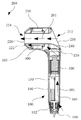
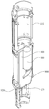
도 1 및 도 2에 도시된 바와 같이, 일 실시예에서의 모발 건조장치(10)는 손잡이(100)와 바디부(200)를 포함한다. 바디부(200)는 손잡이(100)와 연결된다. 손잡이(100)와 바디부(200)에는 유체로 하여금 유동하도록 하기 위한 제1 유체통로(101)가 설치된다. 손잡이(100)는 제1 유체입구(112)를 구비한다. 바디부(200)는 제1 유체출구(222)를 구비한다. 제1 유체입구(112)와 제1 유체출구(222)는 연통되어 제1 유체통로(101)를 형성한다. 제1 유체입구(112)와 제1 유체출구(222)는 각각 유체로 하여금 제1 유체통로(101)에 유입되거나 유출되도록 한다.1 and 2, the
도 2에 도시된 바와 같이, 일 실시예에서 손잡이(100)는 대향되게 설치된 제1 엔드(110)와 제2 엔드(120)를 포함한다. 손잡이(100)의 제2 엔드(120)와 바디부(200)는 연결된다. 제1 유체입구(112)눈 손잡이(100)의 제1 엔드(110)에 설치된다. 바디부(200)는 대향되게 설치된 제1 엔드부(210)와 제2 엔드부(220)를 포함한다. 제1 유체출구(222)는 바디부(200)의 제2 엔드부(220)에 설치된다.As illustrated in FIG. 2, in one embodiment, the
나아가, 본 실시예에서 제1 유체통로(101)는 비선형이다. 제1 유체통로(101)는 연통된 제1 단(103)과 제2 단(105)을 포함한다. 제1 단(103)의 연장방향과 제2 단(105)의 연장방향은 수직된다. 제1 단(103)은 손잡이(100) 내에 위치한다. 제2 단(105)은 바디부(200) 내에 위치한다. 즉 유체는 제1 유체통로(101)의 제1 단(103)을 따라 흘러 손잡이(100)를 관통하고 제1 유체통로(101)의 제2 단(105)을 따라 흘러 바디부(200)를 관통한다.Furthermore, in this embodiment, the
도 2에 도시된 바와 같이, 일 실시예에서 모발 건조장치(10)는 팬 어셈블리(300)를 더 포함한다. 팬 어셈블리(300)는 제1 유체통로(101) 내에 설치된다. 본 실시예에서 팬 어셈블리(300)는 제1 유체통로(101)의 제1 단(103) 내에 위치한다. 팬 어셈블리(300)는 유체를 펌핑하여 제1 유체입구(112)를 관통하여 제1 유체통로(101)에 들어가도록 한다.As shown in Figure 2, in one embodiment the
도 2에 도시된 바와 같이, 일 실시예에서 바디부(200)는 제2 유체입구(212)와 제2 유체출구(224)를 더 구비한다. 제2 유체입구(212)와 제2 유체출구(224)는 연통되어 제2 유체통로(201)를 형성한다. 제2 유체입구(212)와 제2 유체출구(224)는 각각 다른 한 가닥의 유체로 하여금 제2 유체통로(201)에 유입되거나 유출되도록 한다. 본 실시예에서 제2 유체입구(212)는 바디부(200)의 제1 엔드부(210)에 설치된다. 제2 유체출구(224)는 바디부(200)의 제2 엔드부(220)에 설치된다.As shown in FIG. 2, in one embodiment, the
팬 어셈블리(300)가 운행할 경우, 팬 어셈블리(300)는 유체를 펌핑하여 이로 하여금 제1 유체입구(112)를 관통하여 제1 유체통로(101)에 진입하도록 함과 동시에 제1 유체출구(222)에 도달하고 또 유동하여 바디부(200)를 관통하며 제1 유체출구(222)로부터 유출된 유체의 작용은 다른 한 가닥의 유체가 제2 유체입구(212)에서 휘감아 흡입되거나 또는 제2 유체통로(201) 내에 끌어들어가고 제2 유체통로(201)를 따라 제2 유체출구(224)를 향해 유동하게 된다. 상기 제2 유체출구(224)를 거쳐 유출된 다른 한 가닥의 유체와 제1 유체출구(222)를 거쳐 유출된 유체는 바디부(200)의 제2 엔드부(220)에서 합류되어 모발 건조장치(10)의 유체의 유출량이 증강하도록 한다.When the
도 2에 도시된 바와 같이, 일 실시예에서 바디부(200)는 케이싱(230) 및 케이싱(230)을 관통하여 설치된 튜브 바디(240)를 포함한다. 제2 유체통로(201)는 튜브 바디(240)에 의해 한정된다. 제2 유체통로(201)는 튜브 바디(240) 내에서 제2 유체입구(212)로부터 제2 유체출구(224)로 연장된다. 제1 유체통로(101)의 제2 단(105)은 튜브 바디(240)와 케이싱(230)의 측벽 사이의 갭에 의해 한정된다. 제1 유체출구(222)의 단면은 환형상을 이룬다. 제1 유체출구(222)는 제2 유체통로(201)를 에워싸고 연장된다.As shown in FIG. 2, in one embodiment, the
도 2에 도시된 바와 같이, 일 실시예에서 모발 건조장치(10)는 히터(400)를 더 포함한다. 히터(400)는 제1 유체통로(101) 내에 설치된다. 본 실시예에서 히터(400)는 제1 유체통로(101)의 제2 단(105) 내에 설치된다. 히터(400)는 튜브 바디(240)를 감싸고 연장된다. 히터(400)는 제1 유체통로(101)의 유체를 가열하는데 사용된다.2, in one embodiment, the
본 실시예에서는 설명의 편리를 위하여 히터(400)에서 제1 유체출구(222)와 가까이에 있는 일단을 히터(400)의 하류단으로 정의하고 히터(400)에서 제1 유체출구(222)와 멀리에 있는 일단을 히터(400)의 상류단으로 정의한다. 유체는 제1 유체입구(112)를 거쳐제1 유체통로(101)에 들어가고 히터(400)의 상류단으로부터 히터(400)의 하류단으로 유동하여 관통한 다음 계속하여 제1 유체통로(101)를 따라 흘러 제1 유체출구(222)에 도달함으로써 히터(400)로 하여금 상기 제1 유체통로(101) 내의 유체에 대하여 선택적으로 직접 가열할 수 있도록 한다. 이 외에 제2 유체통로(201)를 흐르는 다른 한 가닥의 유체는 상기 히터(400)를 통해 간접적으로 가열할 수도 있다.In this embodiment, for convenience of description, one end close to the first fluid outlet 222 in the
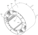
도 3 및 도 4에 도시된 바와 같이, 일 실시예에서 히터(400)는 내층(410)과 가열소자(420)를 포함한다. 내층(410)은 환형구조이다. 내층(410)은 제1 단벽(412), 제2 단벽(414), 제3 단벽(416) 및 제4 단벽(418)을 포함한다. 제1 단벽(412)과 제2 단벽(414)은 대향되게 설치된다. 본 실시예에서 제1 단벽(412)은 히터(400)의 하류단에 위치한다. 제2 단벽(414)은 히터(400)의 상류단에 위치한다. 제3 단벽(416)과 제4 단벽(418)은 대향되게 설치된다. 제3 단벽(416)과 제4 단벽(418)은 제1 단벽(412)과 제2 단벽(414) 사이에 연결되게 설치된다. 제3 단벽(416)과 제4 단벽(418)은 내층(410)의 축방향을 따라 연장된다. 일 실시예에서 내층(410)는 중공구조이고 제3 단벽(416)은 내층(410)의 외측벽을 구성하며 제4 단벽(418)은 내층(410)의 내측벽을 구성한다.3 and 4, in one embodiment, the
가열소자(420)는 가열소자(420)를 통과하는 유체를 가열한다. 가열소자(420)는 내층(410)의 제3 단벽(416)에 설치된다. 구체적으로 가열소자(420)는 전기가 통할 경우 열에너지를 발생하여 가열소자(420)를 통과하는 유체를 가열한다. 가열소자(420)는 단일층이다. 가열소자(420)는 내층(410)의 제3 단벽(416)에 권취된다.The
상기 히터(400)는 가열소자(420)를 단일층으로 설치함으로써 히터(400)의 전체 면적을 감소하여 유체로 하여금 상기 히터(400)를 통과하는 장애물이 더 작도록 하고 유체가 상기 히터(400)를 통과하는 유량손실을 저하시킬 수 있으며 또 한편으로는 유체가 히터(400)를 통과하는 공간이 더 작아 유체의 유속이 빨라지도록 하여 히터(400)의 사용성능을 크게 향상시킴으로써 구조가 간단하고 점용공간이 작은 특점을 가진다.The
일 실시예에서, 내층(410)은 플라스틱 재질로 제조된다. 일 실시예에서 플라스틱 재질은 폴리페닐 에스테르, 폴리벤즈이미다졸, 폴리보론 디페닐실록산, 폴리페닐렌 설파이드, 염화 폴리에테르에서의 임의의 하나이다. 플라스틱 재질은 운모재질보다 더 좋은 가소성을 가지고 경도가 더 높으며 히터(400)의 내층(410)을 플라스틱 재질로 제조되도록 함으로써 상기 가열소자(420)의 단열지지구조인 내층(410)을 기타 형상 및 상대적으로 고정되도록 설치하고, 나아가 기타 구조부품이 상기 가열소자(420)의 단열지지구조로서의 내층(410)에 장착되기 편리하도록 함으로써 히터(400)의 베어링 적응력을 크게 향상시킨다.In one embodiment,
도 3에 도시된 바와 같이, 일 실시예에서 상기 히터(400)는 가열소자(420)를 이격하기 위한 외층(430)을 더 포함한다. 외층(430)은 환형구조이고 외층(430)은 가열소자(420)를 감싸고 연장된다. 가열소자(420)는 내층 내층(410)의 제3 단벽(416)과 외층(430) 사이에 위치한다. 외층(430)은 히터(400) 및 히터(400)를 수용하는 구조를 위해 단열을 제공할 수 있고 이 외에 외층(430)은 가열소자(420)가 내층(410)의 반경방향을 따라 이동하는 것에 대하여 일정한 위치제한작용을 일으킬 수도 있다. 본 실시예에서 외층(430)은 절연재질로 제조되고 바람직하게 외층(430)은 운모로 제조된다.As shown in FIG. 3, in one embodiment, the
도 4에 도시된 바와 같이, 나아가, 외층(430)은 제5 단벽(432), 제6 단벽(434), 제7 단벽(436) 및 제8 단벽(438)을 포함한다. 제5 단벽(432)과 제6 단벽(434)은 대향되게 설치된다. 본 실시예에서 제5 단벽(432)은 히터(400)의 하류단에 위치한다. 제6 단벽(434)은 히터(400)의 상류단에 위치한다. 제7 단벽(436)과 제8 단벽(438)은 대향되게 설치된다. 제7 단벽(436)과 제8 단벽(438)은 제5 단벽(432)과 제6 단벽(434) 사이에 연결되게 설치된다. 제7 단벽(436)과 제8 단벽(438)은 가열소자(420)를 감싸고 연장된다. 가열소자(420)는 내층(410)의 제3 단벽(416)과 외층(430)의 제8 단벽(438) 사이에 위치한다.4, further, the
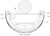
도 5에 도시된 바와 같이, 일 실시예에서 상기 히터(400)는 가열소자(420)를 지지하기 위한 서포트(440)를 더 포함한다. 서포트(440)는 내층(410)의 제3 단벽(416)에 설치되고 내층(410)의 반경방향을 따라 외층(430)을 향해 연장된다. 본 실시예에서 서포트(440)는 절연재질로 제조되고 바람직하게 서포트(440)는 운모로 제조된다.As shown in FIG. 5, in one embodiment, the
도 6 및 도 7에 도시된 바와 같이, 나아가, 서포트(440)는 다수가 포함된다. 다수의 서포트(440)는 제3 단벽(416)의 원주방향을 따라 간격을 두고 배치되어 가열소자(420)의 지지 안정성을 향상시킨다. 일 실시예에서 서포트(440)는 적어도 6개가 포함되는데 적어도 6개의 서포트(440)는 제3 단벽(416)의 원주방향을 따라 간격을 두고 배치된다. 나아가, 서포트(440)에는 가열소자(420)를 포지셔닝하기 위한 포지셔닝 포트(442)가 설치된다. 포지셔닝 포트(442)는 톱니형이다. 가열소자(420)는 서포트(440)의 포지셔닝 포트(442) 내에 위치한다.6 and 7, further, the
일 실시예에서, 가열소자(420)는 금속 와이어이고 이는 톱니형 또는 웨이브형으로 성형된다. 가열소자(420)는 멀티턴으로 인접하여 설치된 코일(422)을 포함한다. 포지셔닝 포트(442)는 다수개 포함된다. 다수의 포지셔닝 포트(442)는 서포트(440)에 동일한 직선을 따라 간격을 두고 설치된다. 가열소자(420)의 멀티턴 코일(422)은 각각 서포트(440)의 다수의 포지셔닝 포트(442) 내에 위치하여 가열소자(420)의 멀티턴 코일(422)을 서로 이격시켜 핫스폿이 히터(400)를 통과하여 유동하는 유체에 대한 한정을 감소시킨다.In one embodiment, the
일 실시예에서, 코일(422)로부터 제3 단벽(416)까지의 최대거리는 6~9mm로써 코일(422)의 에너지 밀도를 담보하는 전제하에 코일(422)이 제3 단벽(416)에 대해 흔들리는 것을 방지하여 히터(400)의 사용 안정성을 향상시킨다.In one embodiment, the maximum distance from the
일 실시예에서, 코일(422)은 서로 연결된 제1 절곡부(4222)와 제2 절곡부(4224)를 포함한다. 제1 절곡부(4222)와 제2 절곡부(4224)는 모두 제3 단벽(416)에 권취된다. 제2 절곡부(4224)가 내층(410)의 원주방향을 따른 길이는 제1 절곡부(4222)가 내층(410)의 원주방향을 따른 길이보다 크다. 상기 구조의 설치를 통해 코일(422)과 제3 단벽(416) 사이의 공간을 확장하는데 유리하여 코일(422)과 제3 단벽(416) 사이의 기타 소자의 장착을 위해 더 양호하게 자리를 내어줄 수 있다.In one embodiment, the
일 실시예에서, 가열소자(420)는 적어도 두개의 독립적인 가열유닛을 포함한다. 가열유닛은 전기가 통할 경우 열 에너지를 발생한다. 이렇게 설치하면 사용자는 독립적으로 매 하나의 가열유닛을 제어할 수 있으므로 저온설치에 대하여 하나의 가열유닛만 사용함과 동시에 가열소자(420)에서의 어느 한 가열유닛이 파손되더라도 히터(400)의 정상적인 사용을 담보할 수 있어 히터(400)의 사용성능을 크게 향상시킬 수 있다.In one embodiment, the
나아가, 본 실시예에서 가열소자(420)는 두개의 독립적인 가열유닛을 포함한다. 이해할 수 있는 것은, 기타 실시예에서 가열유닛의 수량은 세 개 이상 설치할 수 있는데 구체적인 설치방식은 실제 상황에 근거하여 합리적으로 선택할 수 있다. 본 실시예에서 매 하나의 가열유닛은 멀티턴하게 인접하여 설치한 코일(422)을 포함한다.Furthermore, the
도 6 및 도 7에 도시된 바와 같이, 일 실시예에서 모발 건조장치(10)는 온도검출기(500)를 더 포함할 수 있다. 온도검출기(500)는 제1 유체통로(101) 내에 설치된다. 온도검출기(500)는 서미스터 일 수 있으나 이에 한정되지 않는다. 온도검출기(500)는 제1 유체통로(101) 내의 유체의 온도를 검출한다. 히터(400)가 위치하는 제1 유체통로(101)의 제1 유체입구(112) 또는 제1 유체출구(222)가 막힐 경우 가열소자(420)에서의 유체의 유동이 한정되므로 상기 유체가 가열소자(420)의 열량을 제때에 가져갈 수 없어 가열소자(420)가 과열상태에 놓일 수 있게 되는데 온도검출기(500)는 제1 유체통로(101) 내의 유체의 온도를 제때에 검출하여 사용자로 하여금 온도검출기(500)의 검출결과에 근거하여 가열소자(420)의 과열 여부를 판정하도록 함으로써 히터(400)가 제2 유체통로(101) 내의 유체에 대한 가열을 정확히 제어하여 모발 건조장치(10)의 정상적인 사용을 담보할 수 있다.6 and 7, in one embodiment, the
나아가, 본 실시예에서 온도검출기(500)는 히터(400)의 하류단에 설치된다. 구체적으로 온도검출기(500)는 내층(410)의 제1 단벽(412)에 설치된다. 온도검출기(500)는 히터(400)와 제1 유체출구(222) 사이의 유체의 온도를 검출한다. 히터(400)와 제1 유체출구(222) 사이의 유체의 온도가 모발 건조장치(10)의 실제 유출 바람온도와 더 가까우므로 온도검출기(500)를 히터(400)의 하류단에 대향하는 설치는 온도검출기(500)로 하여금 상기 히터(400)와 제1 유체출구(222) 사이의 유체의 온도를 그 온도검출의 참조표준으로 사용하여 히터(400)가 제1 유체통로(101) 내의 유체에 대한 가열을 정확히 제어하도록 할 수 있다.Furthermore, in this embodiment, the
도 6 및 도 7에 도시된 바와 같이, 일 실시예에서 모발 건조장치(10)는 제1 과열보호부재(600)를 더 포함할 수 있다. 제1 과열보호부재(600)는 제1 유체통로(101) 내에 설치되고 가열소자(420)와 전기적으로 연결된다. 제1 과열보호부재(600)는 금속 탄성편일 수 있으나 이에 한정되지 않는다. 제1 과열보호부재(600)는 제1 유체통로(101) 내의 유체의 온도가 제1 기설정 임계값에 도달할 경우 가열소자(420)에 액세스 한 전력을 차단하고 또 제1 유체통로(101) 내의 유체의 온도가 제1 기설정 임계값보다 낮을 경우 가열소자(420)에 액세스 한 전력을 도통한다.6 and 7, in one embodiment, the
제1 과열보호부재(600)는 통상적인 사용에서 유동하여 경유하는 유체의 영향을 받지 않지만 제1 유체통로(101)의 제1 유체입구(112) 또는 제1 유체출구(222)이 막힐 경우 제1 유체통로(101) 내의 유체의 온도는 상승하게 되고 제1 유체통로(101) 내의 유체의 온도가 제1 기설정 임계값에 도달할 경우 제1 과열보호부재(600)는 가열소자(420)에 액세스한 전력을 차단하며 제1 유체통로(101) 내의 유체의 온도가 제1 기설정 임계값보다 낮을 경우 제1 과열보호부재(600)는 가열소자(420)에 액세스한 전력을 다시 도통하여 히터(400)가 제1 유체통로(101) 내의 유체에 대한 가열을 효과적으로 제어함으로써 모발 건조장치(10)의 사용 안전성능을 담보한다.The first
본 실시예에서, 제1 과열보호부재(600)는 내층(410)의 제3 단벽(416)과 가열소자(420) 사이에 설치된다. 구체적으로 제1 과열보호부재(600)는 내층(410)의 제3 단벽(416) 내에 임베드된다. 가열소자(420) 내부의 유체의 온도가 상대적으로 균일하므로 제1 과열보호부재(600)를 가열소자(420) 내부와 대향되도록 설치함으로써 제1 과열보호부재(600)로 하여금 상기 가열소자(420) 내부의 유체의 온도를 그가 가열소자(420)에 액세스한 전력을 차단하거나 도통하도록 제어하는 온도표준으로 하여 히터(400)가 제1 유체통로(101) 내의 유체에 대한 가열을 정확히 제어하도록 한다.In this embodiment, the first
도 6 및 도 7에 도시된 바와 같이, 일 실시예에서 모발 건조장치(10)는 제2 과열보호부재(700)를 더 포함할 수 있다. 제2 과열보호부재(700)는 제1 유체통로(101) 내에 설치되고 가열소자(420)와 전기적으로 연결된다. 제2 과열보호부재(700)는 열퓨즈 일 수 있으나 이에 한정되지 않는다. 제2 과열보호부재(700)는 제1 유체통로(101) 내의 유체의 온도가 제2 기설정 임계값에 도달할 경우 가열소자(420)에 액세스한 전력을 오프시킴과 동시에 차단한다.6 and 7, in one embodiment, the
나아가, 제2 기설정 임계값은 제1 기설정 임계값보다 크다. 제2 과열보호부재(700)는 제1 과열보호부재(600)가 효력을 잃은 상황에서 작동하는데 제1 유체통로(101) 내의 유체의 온도가 제2 기설정 임계값에 도달할 경우 제2 과열보호부재(700)는 가열소자(420)에 액세스한 전력을 차단하여 히터(400)가 제1 유체통로(101) 내의 유체에 대한 가열을 더 효과적으로 제허함으로써 모발 건조장치(10)의 사용 안정성능을 담보한다.Furthermore, the second preset threshold is greater than the first preset threshold. The second
본 실시예에서, 제2 과열보호부재(700)는 내층(410)의 제3 단벽(416)에 임베드됨과 동시에 가열소자(420)의 내부에 위치한다. 제1 과열보호부재(600)의 설치와 유사하게 상기 제2 과열보호부재(700)는 가열소자(420) 내부와 대향되도록 설치함으로써 제2 과열보호부재(700)로 하여금 상기 가열소자(420) 내부의 유체의 온도를 그가 가열소자(420)에 액세스한 전력을 차단하거나 도통하도록 제어하는 온도표준으로 하여 히터(400)가 제1 유체통로(101) 내의 유체에 대한 가열을 정확히 제어하도록 한다.In this embodiment, the second
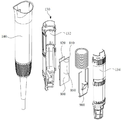
도 8에 도시된 바와 같이, 일 실시예에서 상기 모발 건조장치(10)는 컨트롤러(800)를 더 포함할 수 있다. 컨트롤러(800)는 제1 유체통로(101) 내에 설치되고 손잡이(100) 내에 위치한다. 컨트롤러(800)가 제1 유체통로(101) 내에 설치되고 손잡이(100) 내에 위치하므로 유체가 손잡이(100)에 위치하는 제1 유체통로(101)를 경유하는 과정에 유체는 컨트롤러(800)가 발생한 열량을 제때에 가져가 컨트롤러(800)의 방열에 유리하여 손잡이(100) 또는 바디부(200) 내에 별도의 라디에이터를 설치하여 컨틀로러(800)를 방열시키는 것을 방지함으로써 모발 건조장치(10)의 부품의 수량을 감소하고 생산원가를 저하시킬 수 있다.As shown in FIG. 8, in one embodiment, the
지적해야 할 것은, 본 실시예에서 컨트롤러(800)는 팬 어셈블리(300) 및 히터(400)와 전기적으로 연결된다. 컨트롤러(800)는 히터(400)의 가열온도 및 팬 어셈블리(300)의 회전속도를 제어할 수 있다. 나아가, 컨트롤러(800)와 온도검출기(500)는 전기적으로 연결된다. 컨트롤러(800)는 온도검출기(500)의 검출결과에 근거하여 히터(400)의 가열온도를 제어할 수 있다.It should be noted that in this embodiment, the
도 9 내지 도 11에 도시된 바와 같이, 일 실시예에서 손잡이(100)의 내측벽에는 포지셔닝 홈(150)이 설치된다. 컨트롤러(800)는 포지셔닝 홈(150) 내에 수용된다. 포지셔닝 홈(150)의 대향하는 두 내측벽에는 버클(160)이 설치된다. 버클(160)는 컨트롤러(800)의 양단을 압력 지지하여 컨트롤러(800)를 포지셔닝 홈(150)의 바닥벽에 고정시킨다.9 to 11, in one embodiment, a
나아가, 포지셔닝 홈(150)의 대향하는 두 내측벽에는 모두 다수의 버클(160)이 설치되어 컨트롤러(800)가 포지셔닝 홈(150) 내에서의 장착 안정성을 향상시킨다. 본 실시예에서 포지셔닝 홈(150)의 대향하는 두 내측벽에는 모두 두 개의 버클(160)이 설치된다. 네 개의 버클(160)은 각각 컨트롤러(800)의 네 개의 코너부에 압력 지지된다. 이해할 수 있는 것은, 포지셔닝 홈(150)의 대향하는 두 내측벽에 설치된 버클(160)의 수량은 세 개 이상 일 수 있는데 구체적인 설치방식은 실제 상황에 근거하여 합리적으로 선택할 수 있다.Furthermore, a plurality of
도 8에 도시된 바와 같이, 일 실시예에서 컨트롤러(800)는 제1 제어부(820) 및 제2 제어부(840)를 포함한다. 제1 제어부(820)와 제2 제어부(840)는 전기적으로 연결된다. 즉 본 실시형태에서 컨트롤러(800)는 분리식 구조인 바, 이렇게 되면 컨트롤러(800)의 구조로 하여금 더 컴팩트하도록 하여 손잡이(100) 내의 공간을 더 충부히 이용하도록 할 수 있어 컨트롤러(800)가 한 방향에서의 사이즈를 절감시켜 모발 건조장치(10)의 부피를 절감시킬 수 있게 된다. 또한 제1 제어부(820)와 제2 제어부(840) 에서의 하나가 파손될 경우 파손된 구조만 수리하면 되므로 수리원가를 크게 저하시킨다. 나아가, 본 실시형태에서 제1 제어부(820)와 제2 제어부(840)는 대향되게 설치된다.As shown in FIG. 8, in one embodiment, the
이해할 수 있는 것은, 일 실시예에서 컨트롤러(800)는 연결부재를 더 포함한다. 제1 제어부(820)는 연결부재를 통해 제2 제어부(840)와 연결된다. 일 실시예에서 연결부재는 핀이고 일 실시예에서 연결부재는 조립된 핀과 핀헤더를 포함하며 핀과 핀헤더는 삽입 연결된다. 제1 제어부(820)와 제2 제어부(840)가 연결부재를 통해 상대적인 고정을 유지하면 컨트롤러(800)와 손잡이(100)를 조립할 경우 제1 제어부(820)와 제2 제어부(840)에서의 하나와 손잡이(100)를 고정시키기만 하면 된다.It is understood that, in one embodiment, the
도 8에 도시된 바와 같이, 언급할 가치가 있는 것은, 본 실시형태에서 제1 제어부(820)와 제2 제어부(840)는 모두 장방체 형상을 이루는데 이렇게 되면 제조 난이도를 저하시킬 수 있고 생산효율을 향상시킬 수 있다. 기타 실시형태에서 제1 제어부(820)와 제2 제어부(840)은 단면형상이 원형, 타원형 등 기타 형태일 수 있다.As shown in FIG. 8, it is worth mentioning that, in the present embodiment, the
도 8에 도시된 바와 같이, 일 실시예에서 손잡이(100)는 이너 셀(130)을 포함한다. 이너 셀(130)과 바디부(200)는 연결된다. 이너 셀(130)은 끼움 결합된 제1 이너 셀(132)과 제2 이너 셀(134)을 포함한다. 제1 이너 셀(132)과 제2 이너 셀(134)은 손잡이(100)에 위치한 제1 유체통로(101), 즉 제1 유체통로(101)의 제1 단(103)을 둘러 형성한다. 포지셔닝 홈(150)은 제1 이너 셀(132)과 제2 이너 셀(134)에서의 하나의 내측벽에 설치된다. 포지셔닝 홈(150)의 연장방향과 제1 유체통로(101)의 제1 단(103)의 연장방향은 평행된다. 일 실시예에서 손잡이(100)는 하우징(140)을 더 포함한다. 하우징(140)은 이너 셀(130)에 씌움 설치됨과 동시에 바디부(200)와 연결된다.As shown in FIG. 8, in one embodiment, the
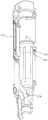
도 8 및 도 10에 도시된 바와 같이, 일 실시예에서 모발 건조장치(10)는 보호커버(900)를 더 포함할 수 있다. 보호커버(900)는 컨트롤러(800)를 커버한다. 보호커버(900)를 설치함으로써 컨트롤러(800)에 대해 일정한 보호작용을 함으로써 손잡이(100)에 위치한 제1 유체통로(101) 내의 유체로 하여금 컨트롤러(800)를 에돌아 흐르도록 할 수 있고 또 한편으로 컨트롤러(800)의 하나 또는 다수의 부품에 오류가 발생할 경우 보호커버(900)는 댐퍼로 작용할 수 있어 컨트롤러(800)에서 오류가 발생한 부품이 저지되어 바디부(200)에 위치한 제1 유체통로(101) 내에 진입할 수 없도록 한다.8 and 10, in one embodiment, the
도 10에 도시된 바와 같이, 일 실시예에서 보호커버(900)의 일단은 경사면(920)을 구비한다. 경사면(920)과 손잡이(100)의 연장방향은 협각을 이룬다. 이렇게 설치되면 유체가 제1 유체통로(101) 내에서 유동하여 보호커버(900)를 관통하는 과정에 일정한 가이드 작용을 제공함으로써 유체가 유동하여 보호커버(900)를 관통할 경우 유동방향의 수직 변화로 인한 제1 유체통로(101) 내의 난류를 절감시켜, 나아가 소음을 절감시키는 목적에 도달할 수 있게 된다. As shown in FIG. 10, in one embodiment, one end of the
도 9 및 도 10에 도시된 바와 같이, 본 실시예에서 포지셔닝 홈(150)은 제1 이너 셀(132)의 내측벽에 설치된다. 제1 이너 셀(132)의 내측벽에는 지지부(170)가 더 설치된다. 컨트롤러(800)는 제2 이너 셀(134)을 향해 돌출 연장된 커패시터부(860)를 구비한다. 구체적으로 커패시터부(860)는 제2 제어부(840)가 제1 제어부(820)와 멀어지는 일측에 설치된다. 보호커버(900)는 지지부(170)와 커패시터부(860) 사이에 걸려 위치 제한된다.9 and 10, in this embodiment, the
도 12에 도시된 바와 같이, 나아가, 제2 이너 셀(134)의 내측벽에는 압접부(180)가 설치된다. 압접부(180)는 보호커버(900)를 압력 지지하여 보호커버(900)를 컨트롤러(800)에 고정시킬 수 있다. 구체적으로 압접부(180)는 다수개 포함할 수 있다. 다수의 압접부(180)는 진열배치를 이루어 제2 이너 셀(134)의 내측벽에 분포됨으로써 보호커버(900)가 컨트롤러(800)에 대한 압접 안정성을 향상시킨다.12, further, a
이상에서 설명한 실시예의 각 기술적 특징은 임의로 조합될 수 있는데 설명의 간결함을 위하여 상술한 실시예에서의 각 기술적 특징의 모든 가능한 조합을 모두 설명하지 않았으나 이러한 기술적 특징의 조합이 모순되지 않는 한 모두 본 명세서에 기재된 범위에 속하는 것으로 간주하여야 한다.Each of the technical features of the above-described embodiments may be arbitrarily combined. For the sake of brevity, all possible combinations of the technical features in the above-described embodiments are not described, but all of the specification are inconsistent unless the combination of these technical features is contradictory. It should be regarded as belonging to the range described in.
이상에서 설명한 실시예는 단지 본 발명의 몇가지 실시형태를 나타내는 바, 이의 설명은 비교적 구체적이고 상세하지만 이로써 본 발명의 특허범위를 한정하는 것으로 이해되어서는 아니된다. 지적해야 할 것은, 본 발명이 속하는 기술분야에서 통상의 지식을 가진 자에게 있어서 본 발명의 사상을 벗어나지 않는 전제하여 약간의 변형과 개선을 진행할 수 있는데 이는 모두 본 발명의 보호범위에 속한다. 따라서 본 발명특허의 보호범위는 첨부된 청구범위를 기준으로 해야 한다.The embodiments described above represent only some embodiments of the present invention, the description of which is relatively specific and detailed, but should not be construed as limiting the scope of the invention. It should be pointed out that for those skilled in the art to which the present invention pertains, slight modifications and improvements can be made on the premise that they do not depart from the spirit of the present invention, and all belong to the protection scope of the present invention. Therefore, the protection scope of the invention patent should be based on the appended claims.
Claims (16)
상기 제3 단벽에 설치되는 가열소자를 포함하는 것을 특징으로 하는 히터.It is made of a plastic material, and includes a first end wall, a second end wall, a third end wall, and a fourth end wall, wherein the first end wall and the second end wall are installed to face each other, and the third end wall and the fourth end wall are An inner layer installed to face each other, and the third end wall and the fourth end wall are connected to and installed between the first end wall and the second end wall; And
And a heating element installed on the third end wall.
상기 내층은 중공구조이고, 상기 제3 단벽은 상기 내층의 외측벽을 구성하며, 상기 제4 단벽은 상기 내층의 내측벽을 구성하는 것을 특징으로 하는 히터.According to claim 1,
The inner layer has a hollow structure, the third end wall constitutes an outer wall of the inner layer, and the fourth end wall constitutes an inner wall of the inner layer.
상기 내층은 환형구조이고, 상기 제3 단벽과 상기 제4 단벽은 상기 내층의 축방향을 따라 연장되며, 상기 가열소자는 상기 제3 단벽에 권취되는 것을 특징으로 하는 히터.According to claim 1,
The inner layer has an annular structure, and the third end wall and the fourth end wall extend along an axial direction of the inner layer, and the heating element is wound on the third end wall.
상기 가열소자를 이격시키는 외층을 더 포함하되, 상기 외층은 환형구조이고, 상기 외층은 상기 가열소자를 감싸고 연장되며, 상기 가열소자는 상기 제3 단벽과 상기 외층 사이에 위치하는 것을 특징으로 하는 히터.According to claim 3,
A heater further comprising an outer layer separating the heating element, the outer layer having an annular structure, the outer layer surrounding and extending the heating element, and the heating element positioned between the third end wall and the outer layer. .
상기 외층은 제5 단벽, 제6 단벽, 제7 단벽 및 제8 단벽을 포함하되, 상기 제5 단벽과 상기 제6 단벽은 대향되게 설치되고, 상기 제7 단벽과 상기 제8 단벽은 대향되게 설치되며, 상기 제7 단벽과 상기 제8 단벽은 상기 제5 단벽과 상기 제6 단벽 사이에 연결 설치되고, 상기 제7 단벽과 상기 제8 단벽은 상기 가열소자를 감싸고 연장되며, 상기 가열소자는 상기 제3 단벽과 상기 제8 단벽 사이에 위치하는 것을 특징으로 하는 히터.The method of claim 4,
The outer layer includes a fifth end wall, a sixth end wall, a seventh end wall, and an eighth end wall, wherein the fifth end wall and the sixth end wall are installed to face each other, and the seventh end wall and the eighth end wall are installed to face each other. The seventh end wall and the eighth end wall are connected to and installed between the fifth end wall and the sixth end wall, and the seventh end wall and the eighth end wall surround and extend the heating element, and the heating element is the A heater, located between the third end wall and the eighth end wall.
상기 가열소자를 지지하는 서포트를 더 포함하되, 상기 서포트는 상기 제3 단벽에 설치되고, 상기 내층의 반경방향을 따라 상기 외층을 향해 연장되는 것을 특징으로 하는 히터.The method of claim 4,
A heater further comprising a support for supporting the heating element, wherein the support is installed on the third end wall and extends toward the outer layer along a radial direction of the inner layer.
상기 서포트와 상기 외층에서의 적어도 하나는 절연재질로 제조되는 것을 특징으로 하는 히터.The method of claim 6,
Heater, characterized in that at least one of the support and the outer layer is made of an insulating material.
상기 서포트는 다수개를 포함하는데 다수의 상기 서포트는 상기 제3 단벽의 원주방향을 따라 간격을 두고 배치되는 것을 특징으로 하는 히터.The method of claim 6,
The support includes a plurality of heaters, wherein the plurality of supports are arranged at intervals along the circumferential direction of the third end wall.
상기 서포트는 적어도 6개를 포함하는데 적어도 6개의 상기 서포트는 상기 제3 단벽의 원주방향을 따라 간격을 두고 배치되는 것을 특징으로 하는 히터.The method of claim 8,
The support includes at least six, wherein at least six of the supports are arranged at intervals along the circumferential direction of the third end wall.
상기 서포트에는 상기 가열소자를 포지셔닝하기 위한 포지셔닝 포트가 설치되는 것을 특징으로 하는 히터.The method of claim 6,
A heater characterized in that the support is provided with a positioning port for positioning the heating element.
상기 포지셔닝 포트는 다수개를 포함하고, 다수의 상기 포지셔닝 포트는 동일한 직선을 따라 상기 서포트에 간격을 두고 설치되며, 상기 가열소자는 멀티턴하게 인접하여 설치된 코일을 포함하고, 상기 가열소자의 멀티턴 코일은 다수의 상기 포지셔닝 포트 내에 위치하는 것을 특징으로 하는 히터.The method of claim 10,
The positioning port includes a plurality, the plurality of positioning ports are installed at intervals to the support along the same straight line, the heating element comprises a coil installed adjacent to the multi-turn, multi-turn of the heating element The heater is characterized in that the coil is located in a number of said positioning ports.
상기 코일은 톱니형 또는 웨이브형인 것을 특징으로 하는 히터.The method of claim 11,
The coil is serrated or wave heater.
상기 코일로부터 상기 제3 단벽까지의 최대거리는 6~9mm인 것을 특징으로 하는 히터.The method of claim 12,
The heater, characterized in that the maximum distance from the coil to the third end wall is 6 ~ 9mm.
상기 코일은 서로 연결된 제1 절곡부와 제2 절곡부를 포함하고, 상기 제1 절곡부와 상기 제2 절곡부는 모두 상기 제3 단벽에 권취되며, 상기 제2 절곡부가 상기 내층의 원주방향을 따른 길이는 상기 제1 절곡부가 상기 내층의 원주방향을 따른 길이보다 큰 것을 특징으로 하는 히터.The method of claim 12,
The coil includes a first bent portion and a second bent portion connected to each other, and both the first bent portion and the second bent portion are wound on the third end wall, and the second bent portion is length along the circumferential direction of the inner layer. The heater is characterized in that the first bent portion is larger than the length along the circumferential direction of the inner layer.
상기 플라스틱 재질은 폴리페닐 에스테르, 폴리벤즈이미다졸, 폴리보론 디페닐실록산, 폴리페닐렌 설파이드, 염화 폴리에테르에서의 임의의 하나인 것을 특징으로 하는 히터.According to claim 1,
The plastic material is a polyphenyl ester, polybenzimidazole, polyboron diphenylsiloxane, polyphenylene sulfide, heaters, characterized in that any one in polyether chloride.
Applications Claiming Priority (3)
| Application Number | Priority Date | Filing Date | Title |
|---|---|---|---|
| CN201811298440.4A CN109043790A (en) | 2018-10-31 | 2018-10-31 | Heater and trichoxerosis device |
| CN201811298440.4 | 2018-10-31 | ||
| PCT/CN2019/087810 WO2020087911A1 (en) | 2018-10-31 | 2019-05-21 | Heater and hair drying device |
Publications (2)
| Publication Number | Publication Date |
|---|---|
| KR20200051513A true KR20200051513A (en) | 2020-05-13 |
| KR102329856B1 KR102329856B1 (en) | 2021-11-22 |
Family
ID=64788964
Family Applications (1)
| Application Number | Title | Priority Date | Filing Date |
|---|---|---|---|
| KR1020197023962A KR102329856B1 (en) | 2018-10-31 | 2019-05-21 | hair dryer |
Country Status (3)
| Country | Link |
|---|---|
| KR (1) | KR102329856B1 (en) |
| CN (1) | CN109043790A (en) |
| WO (1) | WO2020087911A1 (en) |
Families Citing this family (3)
| Publication number | Priority date | Publication date | Assignee | Title |
|---|---|---|---|---|
| CN209331292U (en) * | 2018-10-31 | 2019-09-03 | 舒可士(深圳)科技有限公司 | Overheat protector structure and trichoxerosis device |
| CN109156965A (en) * | 2018-10-31 | 2019-01-08 | 舒可士(深圳)科技有限公司 | Trichoxerosis device |
| CN109043790A (en) * | 2018-10-31 | 2018-12-21 | 舒可士(深圳)科技有限公司 | Heater and trichoxerosis device |
Citations (3)
| Publication number | Priority date | Publication date | Assignee | Title |
|---|---|---|---|---|
| KR20160021265A (en) * | 2013-07-05 | 2016-02-24 | 다이슨 테크놀러지 리미티드 | A handheld appliance |
| KR20160021881A (en) * | 2013-07-16 | 2016-02-26 | 다이슨 테크놀러지 리미티드 | Heater for a hand held appliance |
| KR20180069894A (en) * | 2015-10-21 | 2018-06-25 | 다이슨 테크놀러지 리미티드 | Hair care equipment |
Family Cites Families (6)
| Publication number | Priority date | Publication date | Assignee | Title |
|---|---|---|---|---|
| DE2849266C2 (en) * | 1978-11-14 | 1982-02-04 | Fritz Eichenauer GmbH & Co KG, 6744 Kandel | Electric radiator for gaseous media |
| GB2515808B (en) * | 2013-07-05 | 2015-12-23 | Dyson Technology Ltd | A handheld appliance |
| GB2543538B (en) * | 2015-10-21 | 2018-05-09 | Dyson Technology Ltd | A haircare appliance |
| GB2545225B (en) * | 2015-12-09 | 2018-05-02 | Dyson Technology Ltd | A handheld appliance |
| CN109043790A (en) * | 2018-10-31 | 2018-12-21 | 舒可士(深圳)科技有限公司 | Heater and trichoxerosis device |
| CN109156967A (en) * | 2018-10-31 | 2019-01-08 | 舒可士(深圳)科技有限公司 | Heater and trichoxerosis device |
-
2018
- 2018-10-31 CN CN201811298440.4A patent/CN109043790A/en active Pending
-
2019
- 2019-05-21 WO PCT/CN2019/087810 patent/WO2020087911A1/en active Application Filing
- 2019-05-21 KR KR1020197023962A patent/KR102329856B1/en active IP Right Grant
Patent Citations (3)
| Publication number | Priority date | Publication date | Assignee | Title |
|---|---|---|---|---|
| KR20160021265A (en) * | 2013-07-05 | 2016-02-24 | 다이슨 테크놀러지 리미티드 | A handheld appliance |
| KR20160021881A (en) * | 2013-07-16 | 2016-02-26 | 다이슨 테크놀러지 리미티드 | Heater for a hand held appliance |
| KR20180069894A (en) * | 2015-10-21 | 2018-06-25 | 다이슨 테크놀러지 리미티드 | Hair care equipment |
Also Published As
| Publication number | Publication date |
|---|---|
| CN109043790A (en) | 2018-12-21 |
| WO2020087911A1 (en) | 2020-05-07 |
| KR102329856B1 (en) | 2021-11-22 |
Similar Documents
| Publication | Publication Date | Title |
|---|---|---|
| KR20200051513A (en) | Heater and hair dryer | |
| CN206699677U (en) | Hair care appliance | |
| US6442341B1 (en) | Simple-type fluid heating tube structural arrangement | |
| WO2021052320A1 (en) | Electric hair dryer | |
| KR102296989B1 (en) | Over-temperature protection structure and hair drying apparatus | |
| CN113302353B (en) | Electric heater for household appliances | |
| WO2020087912A1 (en) | Hair drying device | |
| US20200128937A1 (en) | Heater and hair drying apparatus | |
| KR200405016Y1 (en) | A heating device of boiler using high frequency induction heating | |
| CN218500180U (en) | Heater and hair drier | |
| KR102292835B1 (en) | Radiant Heat Emitting Electric Heater | |
| CN109156967A (en) | Heater and trichoxerosis device | |
| CN209171521U (en) | Trichoxerosis device | |
| CN210471913U (en) | Heating device and water dispenser with same | |
| CN210471912U (en) | Heating device and water dispenser with same | |
| CN209403878U (en) | Heater and trichoxerosis device | |
| CN209315091U (en) | Heater and trichoxerosis device | |
| CN218418800U (en) | Heater and hair-dryer | |
| CN217218396U (en) | Heating core of electric heating hair drier | |
| CN208676493U (en) | The fever frame of hair dryer | |
| CN219141073U (en) | Instant heating body | |
| WO2020087710A1 (en) | Over-temperature protection structure and hair drying device | |
| WO2022199391A1 (en) | Hand dryer, heating device, air adjusting device for hand dryer, and air blowing equipment | |
| WO2024007658A1 (en) | Heater and hair care device | |
| CN218328678U (en) | Heating body subassembly and hair-dryer |
Legal Events
| Date | Code | Title | Description |
|---|---|---|---|
| E902 | Notification of reason for refusal | ||
| E90F | Notification of reason for final refusal | ||
| E701 | Decision to grant or registration of patent right | ||
| GRNT | Written decision to grant |