KR20200051485A - Decelerator system, correction method of command value to drive unit, correction data generation method and method for manufacturing decelerator system - Google Patents
Decelerator system, correction method of command value to drive unit, correction data generation method and method for manufacturing decelerator system Download PDFInfo
- Publication number
- KR20200051485A KR20200051485A KR1020190136056A KR20190136056A KR20200051485A KR 20200051485 A KR20200051485 A KR 20200051485A KR 1020190136056 A KR1020190136056 A KR 1020190136056A KR 20190136056 A KR20190136056 A KR 20190136056A KR 20200051485 A KR20200051485 A KR 20200051485A
- Authority
- KR
- South Korea
- Prior art keywords
- reducer
- correction data
- robot
- correction
- reduction gear
- Prior art date
Links
Images


Classifications
-
- B—PERFORMING OPERATIONS; TRANSPORTING
- B25—HAND TOOLS; PORTABLE POWER-DRIVEN TOOLS; MANIPULATORS
- B25J—MANIPULATORS; CHAMBERS PROVIDED WITH MANIPULATION DEVICES
- B25J9/00—Programme-controlled manipulators
- B25J9/16—Programme controls
- B25J9/1628—Programme controls characterised by the control loop
- B25J9/1633—Programme controls characterised by the control loop compliant, force, torque control, e.g. combined with position control
-
- B—PERFORMING OPERATIONS; TRANSPORTING
- B25—HAND TOOLS; PORTABLE POWER-DRIVEN TOOLS; MANIPULATORS
- B25J—MANIPULATORS; CHAMBERS PROVIDED WITH MANIPULATION DEVICES
- B25J9/00—Programme-controlled manipulators
- B25J9/16—Programme controls
- B25J9/1602—Programme controls characterised by the control system, structure, architecture
-
- B—PERFORMING OPERATIONS; TRANSPORTING
- B25—HAND TOOLS; PORTABLE POWER-DRIVEN TOOLS; MANIPULATORS
- B25J—MANIPULATORS; CHAMBERS PROVIDED WITH MANIPULATION DEVICES
- B25J9/00—Programme-controlled manipulators
- B25J9/10—Programme-controlled manipulators characterised by positioning means for manipulator elements
- B25J9/102—Gears specially adapted therefor, e.g. reduction gears
-
- B—PERFORMING OPERATIONS; TRANSPORTING
- B25—HAND TOOLS; PORTABLE POWER-DRIVEN TOOLS; MANIPULATORS
- B25J—MANIPULATORS; CHAMBERS PROVIDED WITH MANIPULATION DEVICES
- B25J9/00—Programme-controlled manipulators
- B25J9/16—Programme controls
- B25J9/1628—Programme controls characterised by the control loop
- B25J9/1653—Programme controls characterised by the control loop parameters identification, estimation, stiffness, accuracy, error analysis
-
- B—PERFORMING OPERATIONS; TRANSPORTING
- B25—HAND TOOLS; PORTABLE POWER-DRIVEN TOOLS; MANIPULATORS
- B25J—MANIPULATORS; CHAMBERS PROVIDED WITH MANIPULATION DEVICES
- B25J9/00—Programme-controlled manipulators
- B25J9/16—Programme controls
- B25J9/1656—Programme controls characterised by programming, planning systems for manipulators
- B25J9/1661—Programme controls characterised by programming, planning systems for manipulators characterised by task planning, object-oriented languages
-
- B—PERFORMING OPERATIONS; TRANSPORTING
- B25—HAND TOOLS; PORTABLE POWER-DRIVEN TOOLS; MANIPULATORS
- B25J—MANIPULATORS; CHAMBERS PROVIDED WITH MANIPULATION DEVICES
- B25J9/00—Programme-controlled manipulators
- B25J9/16—Programme controls
- B25J9/1679—Programme controls characterised by the tasks executed
- B25J9/1692—Calibration of manipulator
-
- G—PHYSICS
- G05—CONTROLLING; REGULATING
- G05B—CONTROL OR REGULATING SYSTEMS IN GENERAL; FUNCTIONAL ELEMENTS OF SUCH SYSTEMS; MONITORING OR TESTING ARRANGEMENTS FOR SUCH SYSTEMS OR ELEMENTS
- G05B19/00—Programme-control systems
- G05B19/02—Programme-control systems electric
- G05B19/18—Numerical control [NC], i.e. automatically operating machines, in particular machine tools, e.g. in a manufacturing environment, so as to execute positioning, movement or co-ordinated operations by means of programme data in numerical form
- G05B19/404—Numerical control [NC], i.e. automatically operating machines, in particular machine tools, e.g. in a manufacturing environment, so as to execute positioning, movement or co-ordinated operations by means of programme data in numerical form characterised by control arrangements for compensation, e.g. for backlash, overshoot, tool offset, tool wear, temperature, machine construction errors, load, inertia
Landscapes
- Engineering & Computer Science (AREA)
- Robotics (AREA)
- Mechanical Engineering (AREA)
- Automation & Control Theory (AREA)
- Human Computer Interaction (AREA)
- Manufacturing & Machinery (AREA)
- Physics & Mathematics (AREA)
- General Physics & Mathematics (AREA)
- Manipulator (AREA)
- Numerical Control (AREA)
Abstract
Description
본 발명은, 감속기 시스템, 구동 유닛으로의 지령값의 보정 방법, 보정 데이터의 생성 방법, 및 감속기 시스템의 제조 방법에 관한 것이다.The present invention relates to a speed reducer system, a method for correcting a command value to a drive unit, a method for generating correction data, and a method for manufacturing a speed reducer system.
종래부터, 예를 들어 레이저 용접 용도나 플라스마 용접 용도의 로봇(공작 기계)을 수평면 상에서 직선 동작시켰을 때, 중력 방향의 굴곡 등이 발생하여 가공 정밀도에 악영향을 미치는 것을 알고 있다. 당해 굴곡은 로봇의 손끝 위치를 중력 방향으로 변화시키는 축에 설치된 감속기의 각도 전달 오차에 의해 발생하는 것이라고 여겨져, 지금까지 감속기의 입력측과 출력측에 회전 속도 검출 수단을 마련하여 각도 전달 오차를 개체마다 직접 계측하는 방법 등 다양한 방법이 제안되어 왔다.Conventionally, it has been known that, for example, when a robot (machine tool) for laser welding or plasma welding is linearly operated on a horizontal surface, bending or the like in the direction of gravity occurs, which adversely affects processing precision. The bending is considered to be caused by the angle transmission error of the reducer installed on the axis that changes the position of the robot's fingertip in the direction of gravity, so far, the rotational speed detection means are provided on the input side and the output side of the reducer to directly provide the angle transmission error for each individual. Various methods have been proposed, such as measurement methods.
조립된 로봇에 대해, 작업 공간이 좁은 로봇 가동 현장에 있어서, 인위적 조정 수단을 필요로 하는 일 없이 각도 전달 오차의 보정 파라미터를 동정하는 장치로서, 특허문헌 1이 알려져 있다. 특허문헌 1은, 각 관절부에서 회전 구동하는 모터와, 모터에 연결된 감속기와, 감속기에 연결되는 로봇 암을 구비하는 로봇에 있어서, 로봇의 손끝 위치의 궤적 오차를 보정하기 위해, 각 모터에 대한 각도 지령에 가산되는 보정값의 파라미터를 동정하는 장치이며, 당해 모터에 대한 토크 지령이 최대가 되는 링크 각도에 있어서 최댓값을 취하는, 토크 지령과 동일 주기의 사인파의 위상에 기초하여, 보정값의 위상 파라미터를 동정하고, 또한 동정된 위상 파라미터 및 임의의 진폭 파라미터를 사용하여 계산되는 보정값과 각도 지령의 합계에 대해 순운동학 계산을 행함으로써 얻어지는 로봇의 손끝 위치와 로봇의 현재의 손끝 위치의 차분에 대해 로봇의 동작 시간 내에서의 적분값을 계산하고, 당해 적분값이 최소가 되는 진폭 파라미터를 보정값의 진폭 파라미터로서 동정하는 수단을 구비한 로봇 암 위치 보정 파라미터의 동정 장치를 개시하고 있다.With respect to the assembled robot, Patent Document 1 is known as a device for identifying a correction parameter of an angular transmission error without requiring artificial adjustment means in a robot operation site with a narrow working space. Patent Document 1, in a robot having a motor that rotates at each joint, a reducer connected to the motor, and a robot arm connected to the reducer, in order to correct the trajectory error of the position of the fingertip of the robot, the angle to each motor It is a device to identify the parameter of the correction value added to the command, and takes the maximum value in the link angle at which the torque command to the motor is the maximum, based on the phase of the sine wave of the same period as the torque command, and the phase parameter of the correction value And the difference between the robot's fingertip position and the robot's current fingertip position obtained by performing forward kinematics calculation on the sum of the correction value and angle command calculated using the identified phase parameter and arbitrary amplitude parameter. The integral value within the robot's operating time is calculated, and the amplitude parameter for which the integral value is minimum is corrected. Disclosed is a device for identifying a robot arm position correction parameter having means for identifying as a width parameter.
그러나 특허문헌 1에 개시된 장치에서는, 로봇(공작 기계)의 개체차인 각도 전달 오차의 보정 파라미터를 동정하기 위해 시간이 걸려, 보정 파라미터를 작성하는 동안, 공장 설비의 정지가 필요해져, 생산성이 저하된다고 하는 문제가 있었다. 또한, 로봇의 개체차에 관한 보정 파라미터에 불과하므로, 로봇의 최종 조정을 행할 필요가 있다고 하는 문제가 있었다. 또한, 당해 보정 파라미터는 로봇의 개체차에 관한 것이며, 로봇의 사용 조건에 따른 것은 아니므로, 로봇의 동작의 정밀도가 반드시 충분하다고는 하기 어려웠다.However, in the apparatus disclosed in Patent Document 1, it takes time to identify the correction parameter of the angle transmission error, which is the individual difference of the robot (machine tool), and while creating the correction parameter, it is necessary to stop the factory equipment and productivity decreases. There was a problem. In addition, since it is only a correction parameter for the individual difference of the robot, there is a problem that it is necessary to perform final adjustment of the robot. In addition, since the correction parameter relates to the individual difference of the robot and does not depend on the conditions of use of the robot, it has been difficult to say that the accuracy of the robot's operation is necessarily sufficient.
본 발명의 목적 중 하나는, 초기 기동(초기의 세팅)을 조기에 행할 수 있는 감속기 시스템, 구동 유닛으로의 지령값의 보정 방법, 보정 데이터의 생성 방법, 및 감속기 시스템의 제조 방법을 제공하는 것이다.One of the objects of the present invention is to provide a speed reducer system capable of early starting (initial setting), a method for correcting a command value to a drive unit, a method for generating correction data, and a method for manufacturing the speed reducer system. .
본 발명의 일 실시 형태에 의한 감속기 시스템은, 감속기와, 상기 감속기의 위치 오차에 관한 개체 정보, 및 상기 감속기가 사용되는 사용 조건에서의 보정 정보에 기초하는 보정 데이터를 기억한 메모리를 구비한다.The speed reducer system according to an embodiment of the present invention includes a speed reducer, and a memory storing correction data based on individual information regarding the positional error of the speed reducer and correction information in use conditions in which the speed reducer is used.
본 발명의 일 실시 형태에 의한 감속기 시스템에 있어서는, 상기 보정 데이터가 상기 사용 조건에 있어서의 상기 감속기의 사용으로부터 수집된 위치 데이터에 기초하여 생성된다.In the speed reducer system according to one embodiment of the present invention, the correction data is generated based on the position data collected from the use of the speed reducer in the use condition.
본 발명의 일 실시 형태에 의한 감속기 시스템에 있어서는, 상기 감속기가 사용되는 로봇의 구동 유닛에 상기 보정 데이터가 입력된다.In the reduction gear system according to an embodiment of the present invention, the correction data is input to a driving unit of a robot in which the reduction gear is used.
본 발명의 일 실시 형태에 의한 감속기 시스템에 있어서는, 상기 감속기가 사용되는 로봇의 구동 유닛의 제어부에 상기 보정 데이터가 입력된다.In the reduction gear system according to an embodiment of the present invention, the correction data is input to a control unit of a drive unit of a robot in which the reduction gear is used.
본 발명의 일 실시 형태에 의한 감속기 시스템에 있어서는, 상기 보정 데이터에 의해 상기 제어부가 상기 구동 유닛으로의 지령값을 보정한다.In the reduction gear system according to one embodiment of the present invention, the control unit corrects a command value to the driving unit by the correction data.
본 발명의 일 실시 형태에 의한 감속기 시스템에 있어서, 상기 위치 오차는, (a) 상기 감속기의 각도 전달 오차, (b) 비틀림 오차, 및 (c) 마찰 오차 중 적어도 하나를 포함한다.In the reduction gear system according to an embodiment of the present invention, the position error includes at least one of (a) an angle transmission error of the reduction gear, (b) a torsional error, and (c) a friction error.
본 발명의 일 실시 형태에 의한 감속기 시스템에 있어서, 상기 사용 조건은, (a) 상기 감속기의 종류, (b) 상기 감속기가 사용되는 로봇의 종류, (c) 상기 감속기가 사용되는 로봇의 용도, (d) 상기 감속기가 사용되는 로봇이 취급하는 대상물의 중량, (e) 상기 감속기가 사용되는 로봇이 취급하는 대상물의 이동 거리, 및 (f) 상기 감속기가 사용되는 로봇이 취급하는 대상물의 속도 중 적어도 하나를 포함한다.In the reducer system according to an embodiment of the present invention, the conditions of use include: (a) the type of the reducer, (b) the type of the robot used by the reducer, (c) the use of the robot using the reducer, (d) the weight of the object handled by the robot using the reducer, (e) the moving distance of the object handled by the robot using the reducer, and (f) the speed of the object handled by the robot using the reducer. At least one.
본 발명의 일 실시 형태에 의한 감속기 시스템은, 구동 유닛과, 상기 메모리에 기록한 상기 보정 데이터를 사용하여 상기 구동 유닛의 보정을 행하는, 상기 구동 유닛의 제어부를 포함한다.The speed reducer system according to an embodiment of the present invention includes a drive unit and a control unit of the drive unit that corrects the drive unit using the correction data recorded in the memory.
본 발명의 일 실시 형태에 의한 로봇은, 상기한 감속기 시스템 중 어느 하나를 포함한다.The robot according to one embodiment of the present invention includes any one of the speed reducer systems described above.
본 발명의 일 실시 형태에 의한 보정 방법은, 감속기의 위치 오차에 관한 개체 정보, 및 상기 감속기가 사용되는 사용 조건에서의 보정 정보에 기초하여 보정 데이터에 의해 구동 유닛으로의 지령값을 보정한다.The correction method according to one embodiment of the present invention corrects a command value to the drive unit by correction data based on individual information on the positional error of the speed reducer and correction information in use conditions in which the speed reducer is used.
본 발명의 일 실시 형태에 의한 보정 데이터의 생성 방법은, 감속기의 위치 오차에 관한 개체 정보, 및 상기 감속기가 사용되는 사용 조건에서의 보정 정보에 기초하여 보정 데이터를 생성하고, 상기 보정 데이터를 메모리에 기록한다.In the method of generating correction data according to an embodiment of the present invention, correction data is generated based on individual information on a position error of a reduction gear and correction information in use conditions in which the reduction gear is used, and the correction data is stored in the memory. Record in
본 발명의 일 실시 형태에 의한 감속기 시스템의 제조 방법은, 감속기와 메모리로 이루어지는 감속기 시스템의 제조 방법이며, 상기 감속기의 위치 오차에 관한 개체 정보, 및 상기 감속기가 사용되는 사용 조건에서의 보정 정보에 기초하여 보정 데이터를 생성하고, 상기 보정 데이터를 상기 메모리에 기록하고, 상기 감속기와 상기 메모리를 조합한다.A method of manufacturing a reducer system according to an embodiment of the present invention is a method of manufacturing a reducer system composed of a reducer and a memory, and includes individual information regarding the positional error of the reducer and correction information in use conditions in which the reducer is used. Based on this, correction data is generated, the correction data is written to the memory, and the reducer and the memory are combined.
초기 기동(초기의 세팅)을 조기에 행할 수 있는 감속기 시스템, 구동 유닛으로의 지령값의 보정 방법, 보정 데이터의 생성 방법, 및 감속기 시스템의 제조 방법이 제공된다.A speed reducer system capable of early starting (initial setting), a method for correcting a command value to a drive unit, a method for generating correction data, and a method for manufacturing the speed reducer system are provided.
도 1은 본 발명의 일 실시 형태에 있어서의 감속기 시스템을 구비하는 로봇의 개략도이다.
도 2는 본 발명의 일 실시 형태에 있어서의 보정 데이터를 모식적으로 설명하는 도면이다.
도 3은 본 발명의 일 실시 형태에 있어서의 보정 데이터의 전달 방법을 설명하는 도면이다.1 is a schematic diagram of a robot equipped with a reducer system according to an embodiment of the present invention.
2 is a diagram schematically explaining correction data in one embodiment of the present invention.
3 is a diagram illustrating a method for transmitting correction data in one embodiment of the present invention.
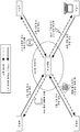
도 1은, 본 발명의 일 실시 형태에 있어서의 감속기 시스템을 구비하는 공작 기계의 개략도를 도시한다. 공작 기계에는, 로봇, 머시닝센터, 포지셔너 등이 포함된다. 본 명세서에서는, 공작 기계로서 로봇(100)이 사용되는 실시 형태에 대해 주로 설명한다.1 shows a schematic diagram of a machine tool equipped with a reducer system according to an embodiment of the present invention. Machine tools include robots, machining centers, positioners, and the like. In the present specification, an embodiment in which the
도시하는 바와 같이, 일 실시 형태에 있어서의 로봇(100)은, 감속기 시스템(1)과, 이 감속기 시스템(1)으로부터 공급되는 구동력에 의해 구동되는 암(6)을 구비한다. 감속기 시스템(1)은, 로봇(100)을 제어하기 위한 제어부(2)와, 구동 유닛(3)과, 감속기(4)를 구비한다. 제어부(2)는, 예를 들어 도시하지 않은 컴퓨터 프로세서와, 메모리(5)를 구비한다. 컴퓨터 프로세서는, 감속기(4)를 제어하기 위한 제어 프로그램 또는 그 이외의 프로그램을 로드하고, 로드한 프로그램에 포함되는 명령을 실행하는 연산 장치이다. 메모리(5)는, 컴퓨터 프로세서에 의해 액세스되는 기억 장치이다. 메모리(5)는, 예를 들어 자기 디스크, 광 디스크, 반도체 메모리, 또는 데이터를 기억 가능한 상기 이외의 각종 기억 장치이다.As illustrated, the
구동 유닛(3)은, 예를 들어 전동 모터이다. 감속기(4)는, 구동 유닛(3)으로부터 입력된 구동력을 감속하여 암(6)에 전달한다. 암(6)은, 감속기(4)로부터의 구동력에 의해 구동된다. 메모리(5)는, 후술하는 보정 데이터를 기억한다. 제어부(2)는, 로봇(100)의 외부에 마련되어도 된다. 일 양태에 있어서, 제어부(2)는, 로봇(100)의 외부에, 구동 유닛(3)과 통신 가능하게 마련된다. 구동 유닛(3)은, 감속기(4)를 포함하도록 구성해도 된다. 또한, 메모리(5)에 기억되어 있는 보정 데이터는, 구동 유닛(3)에 입력되어도 된다.The
제어부(2)는, 로봇(100)에 대한 동작 지령을 생성하고, 당해 동작 지령에 기초하여, 로봇(100)의 각 축(예를 들어, 관절)에 탑재한 구동 유닛(3)을 제어하도록 구성된다. 예를 들어, 제어부(2)는, 로봇(100)에 대한 동작 지령을 나타내는 지령값(지령 신호)을 생성하고, 이 지령값을 구동 유닛(3)에 입력함으로써 구동 유닛(3)을 제어한다. 구동 유닛(3)에 의한 구동력은 감속기(4)에 입력되고, 그 출력에 의해 암(6)이 구동된다. 도시하지 않았지만, 로봇(100)의 구동 유닛(3)에는, 위치 검출기, 각도 검출기, 인코더 및 이들 이외의 센서가 적절하게 마련된다.The
다음으로, 도 2를 참조하여, 보정 데이터(11)를 더 상세하게 설명한다. 보정 데이터(11)의 생성을 위해, 먼저, 로봇(100)의 제조 시에 있어서의 당해 로봇(100)의 개체마다의 위치 오차에 관한 개체차를 나타내는 개체 정보(9)를 준비한다. 본 발명의 일 실시 형태에 있어서, 개체 정보(9)는, 예를 들어 로봇(100) 또는 감속기(4)의 각도 전달 오차, 비틀림 오차, 마찰 오차, 및 이들 이외의 위치 오차 정보를 포함한다.Next, the
또한, 로봇(100)의 사용 조건에 관한 보정 정보(10)를 준비한다. 본 발명의 일 실시 형태에 있어서, 보정 정보(10)는, 감속기(4)의 종류, 로봇(100)의 종류, 로봇(100)의 용도, 로봇(100)이 취급하는 대상물의 중량, 로봇(100)이 취급하는 대상물의 이동 거리, 및 로봇(100)이 취급하는 대상물의 속도, 및 이들 이외의 로봇(100)의 사용 조건에 관한 정보 중 적어도 하나를 포함한다.In addition,
본 발명의 일 실시 형태에 있어서, 보정 데이터(11)는, 이 개체 정보(9)와 보정 정보(10)에 기초하여 생성된다. 보정 데이터(11)는, 개체 정보(9) 및 보정 정보(10) 이외의 정보에 더 기초하여 생성되어도 된다.In one embodiment of the present invention, the
본 발명의 일 실시 형태에 있어서, 로봇(100)에는, 보정 데이터(11)가 입력된다. 제어부(2)는, 보정 데이터(11)에 기초하여 구동 유닛(3)을 구동하기 위한 지령값을 보정하도록 구성된다. 상기한 바와 같이, 로봇(100)에 입력되는 보정 데이터(11)는, 로봇(100)의 개체차를 나타내는 개체 정보(9)와 로봇(100)의 사용 조건에 관한 보정 정보(10)에 기초하여 생성되므로, 로봇(100)의 초기 기동(초기 세팅)보다 전에 보정 데이터(11)를 준비하고, 이 보정 데이터를 로봇(100)에 입력함으로써, 초기 기동을 단시간에 행하는 것이 가능해진다.In one embodiment of the present invention,
본 발명의 일 실시 형태에 있어서는, 구동 유닛(3)에 보정 데이터(11)가 입력되어도 된다. 보정 데이터(11)는, 메모리(5)에 기억되어 있어도 된다. 메모리(5)로부터 판독된 보정 데이터(11)가 구동 유닛(3)에 입력되어도 된다. 일 실시 형태에 있어서는, 구동 유닛(3)에 의해, 제어부(2)로부터의 지령값이 보정 데이터(11)에 기초하여 보정되어도 된다.In one embodiment of the present invention,
본 발명의 일 실시 형태에 있어서는, 제어부(2)에 보정 데이터(11)가 입력되어도 된다. 메모리(5)로부터 판독된 보정 데이터(11)가 제어부(2)에 입력되어도 된다.In one embodiment of the present invention,
본 발명의 일 실시 형태에 관한 보정 방법에 있어서는, 개체 정보(9) 및 보정 정보(10)에 기초하여 보정 데이터(11)를 생성하는 스텝과, 이 보정 데이터(11)에 기초하여 제어부(2)로부터 구동 유닛(3)으로의 지령값을 보정하는 스텝을 구비한다. 일 실시 형태에 있어서의 보정 방법은, 보정 데이터(11)에 기초하여 보정된 지령값이 구동 유닛(3)에 입력되어도 된다. 보정 데이터(11)에 기초하여 보정된 지령값은, 제어부(2)에 입력되어도 된다.In the correction method according to one embodiment of the present invention, a step of generating
본 발명의 일 실시 형태에 관한 보정 데이터(11)의 생성 방법에서는, 개체 정보(9)와 보정 정보(10)에 기초하여 보정 데이터(11)를 생성하는 스텝과, 생성된 보정 데이터(11)를 메모리(5)에 기억하는 스텝을 구비한다. 보정 데이터의 생성 방법은, 보정 정보(10)를 수집하는 스텝을 더 구비해도 된다. 보정 정보(10)는, 로봇(100)마다 수집되어도 된다. 하나의 로봇(100)에 대해 수집되는 보정 정보는, 다른 로봇(100)에 대해 수집되는 보정 정보와 상이한 것이어도 된다. 하나의 로봇(100)에서 사용되는 보정 데이터(11)는, 당해 하나의 로봇(100)에 대해 수집된 보정 정보(10)와, 당해 로봇(100)의 개체 정보(9)에 기초하여 생성되어도 된다.In the method for generating
다음으로, 도 3을 참조하여, 보정 데이터(11)의 전달 방법에 대해 설명한다.Next, with reference to FIG. 3, the delivery method of the
감속기(4)의 제조자 M은, 제조한 감속기(4)마다 제조 시의 위치 오차를 계측하고, 이 위치 오차를 개체 정보(9)로서 기록한다. 또한, 제조자 M은, 감속기(4)(또는 당해 로봇(100))의 사용 시에, 당해 감속기(4)(또는 당해 로봇(100))에 대한 보정 정보(10)를 감속기(4)(또는 로봇(100))의 사용자로부터 수집한다. 제조자 M은, 개체 정보(0)와 보정 정보(10)에 기초하여 보정 데이터(11)를 생성한다.The manufacturer M of the
제조자 M은, 보정 데이터(11)를 축적하고 있으므로, 감속기(4)를 고객에게 제공할 때, 감속기(4)와 함께 당해 감속기(4)에 관한 보정 데이터(11)도 제공할 수 있다. 감속기(4)의 이용자(고객 A∼고객 D)는, 제조자 M으로부터 제공된 보정 데이터(11)에 기초하여 초기 기동(초기 세팅)을 행할 수 있다. 이에 의해, 감속기(4)의 이용자는, 초기 기동을 단시간에 행할 수 있다Since the manufacturer M accumulates the
보정 데이터(11)는, 제조자 M으로부터 고객(예를 들어, 고객 A)에 대해 유선 통신 또는 무선 통신에 의해 송신되어도 된다. 이 유선 또는 무선의 통신로에는, 시큐리티 게이트가 설정될 수 있다. 이 시큐리티 게이트에 의해, 안전성을 확보한 후 보정 데이터(11)가 송수신될 수 있다. 보정 데이터(11)는, 메모리에 기억되어도 된다. 제조자 M은, 보정 데이터(11)를 기억한 메모리를 감속기(4)에 조합해도 된다. 이 경우, 보정 데이터(11)는, 감속기(4)와 함께 제조자 M으로부터 고객(예를 들어, 고객 B)에 대해 제공된다. 보정 데이터(11)는, 감속기(4)와는 별체의 기억 매체에 기록되어도 된다. 이 경우, 제조자 M으로부터 고객(예를 들어, 고객 C)에 대해 보정 데이터(11)가 기억된 기억 매체가 제공된다. 즉, 제조자 M으로부터 고객에게 기억 매체를 제공함으로써, 당해 기억 매체에 기억된 보정 데이터(11)를 고객에게 제공할 수 있다. 보정 데이터(11)는, 종이 매체에 기록되어 있어도 된다. 이 경우, 제조자 M으로부터 고객(예를 들어, 고객 D)에 대해 보정 데이터(11)가 기억된 종이 매체가 제공된다. 이와 같이 하여, 감속기(4)와 함께 보정 데이터(11)도 제공하는 것이 가능해진다.The
상술한 실시 형태의 원리는, 로봇(100) 등의 공작 기계에 한정되지 않고, 다양한 작동 장치, 이동 장치 및 이들 이외의 장치에 적용될 수 있다.The principle of the above-described embodiment is not limited to a machine tool such as the
1: 로봇(공작 기계)
2: 제어부
3: 구동 유닛
4: 감속기
5: 메모리
6: 암
9: 개체 정보
10: 보정 정보
11: 보정 데이터1: Robot (machine tool)
2: Control
3: Drive unit
4: reducer
5: Memory
6: Cancer
9: Object information
10: correction information
11: correction data
Claims (12)
상기 감속기의 위치 오차에 관한 개체 정보, 및 상기 감속기가 사용되는 사용 조건에서의 보정 정보에 기초하는 보정 데이터를 기억한 메모리를
구비한, 감속기 시스템.Reducer,
A memory that stores correction data based on individual information about the position error of the speed reducer and correction information in use conditions in which the speed reducer is used.
Equipped, reducer system.
상기 보정 데이터가 상기 사용 조건에 있어서의 상기 감속기의 사용으로부터 수집된 위치 데이터에 기초하여 생성되는, 감속기 시스템.According to claim 1,
A reduction gear system, wherein the correction data is generated based on position data collected from the use of the reduction gear in the use condition.
상기 감속기가 사용되는 로봇의 구동 유닛에 상기 보정 데이터가 입력되는, 감속기 시스템.According to claim 1,
A reduction gear system in which the correction data is input to a driving unit of a robot in which the reduction gear is used.
상기 감속기가 사용되는 로봇의 구동 유닛의 제어부에 상기 보정 데이터가 입력되는, 감속기 시스템.According to claim 1,
A reduction gear system in which the correction data is input to a control unit of a driving unit of a robot in which the reduction gear is used.
상기 보정 데이터에 의해 상기 제어부가 상기 구동 유닛으로의 지령값을 보정하는, 감속기 시스템.The method of claim 4,
A reduction gear system in which the control unit corrects a command value to the drive unit by the correction data.
상기 위치 오차는,
(a) 상기 감속기의 각도 전달 오차,
(b) 비틀림 오차, 및
(c) 마찰 오차
중 적어도 하나를 포함하는, 감속기 시스템.According to claim 1,
The position error,
(a) the angle transmission error of the reducer,
(b) torsional error, and
(c) friction error
A reducer system comprising at least one of the following.
상기 사용 조건은,
(a) 상기 감속기의 종류,
(b) 상기 감속기가 사용되는 로봇의 종류,
(c) 상기 감속기가 사용되는 로봇의 용도,
(d) 상기 감속기가 사용되는 로봇이 취급하는 대상물의 중량,
(e) 상기 감속기가 사용되는 로봇이 취급하는 대상물의 이동 거리, 및
(f) 상기 감속기가 사용되는 로봇이 취급하는 대상물의 속도,
중 적어도 하나를 포함하는, 감속기 시스템.According to claim 1,
The conditions of use,
(a) the type of the reducer,
(b) the type of robot the reducer is used for,
(c) the use of a robot in which the reducer is used,
(d) the weight of the object to be handled by the robot using the reducer,
(e) the moving distance of the object handled by the robot using the reducer, and
(f) the speed of the object handled by the robot using the reducer,
A reducer system comprising at least one of the following.
구동 유닛과,
상기 메모리에 기록한 상기 보정 데이터를 사용하여 상기 구동 유닛의 보정을 행하는, 상기 구동 유닛의 제어부를 포함하는, 감속기 시스템.According to claim 1,
A drive unit,
And a reduction unit system comprising a control unit of the driving unit for correcting the driving unit using the correction data recorded in the memory.
상기 보정 데이터를 메모리에 기록하는,
보정 데이터의 생성 방법.Compensation data is generated based on the individual information regarding the position error of the speed reducer and the correction information in the use condition in which the speed reducer is used,
Recording the correction data in a memory,
How to generate correction data.
상기 감속기의 위치 오차에 관한 개체 정보, 및 상기 감속기가 사용되는 사용 조건에서의 보정 정보에 기초하여 보정 데이터를 생성하고,
상기 보정 데이터를 상기 메모리에 기록하고,
상기 감속기와 상기 메모리를 조합하는, 감속기 시스템의 제조 방법.It is a manufacturing method of a reducer system consisting of a reducer and a memory,
Compensation data is generated based on the individual information regarding the position error of the speed reducer and the correction information in use conditions in which the speed reducer is used,
Write the correction data to the memory,
A method of manufacturing a reducer system, combining the reducer and the memory.
Applications Claiming Priority (2)
| Application Number | Priority Date | Filing Date | Title |
|---|---|---|---|
| JPJP-P-2018-208375 | 2018-11-05 | ||
| JP2018208375A JP7185495B2 (en) | 2018-11-05 | 2018-11-05 | REDUCER SYSTEM, METHOD OF CORRECTION OF COMMAND VALUE TO DRIVE UNIT, METHOD OF GENERATING CORRECTION DATA, AND METHOD OF MANUFACTURING REDUCER SYSTEM |
Publications (1)
| Publication Number | Publication Date |
|---|---|
| KR20200051485A true KR20200051485A (en) | 2020-05-13 |
Family
ID=70469716
Family Applications (1)
| Application Number | Title | Priority Date | Filing Date |
|---|---|---|---|
| KR1020190136056A KR20200051485A (en) | 2018-11-05 | 2019-10-30 | Decelerator system, correction method of command value to drive unit, correction data generation method and method for manufacturing decelerator system |
Country Status (5)
| Country | Link |
|---|---|
| JP (1) | JP7185495B2 (en) |
| KR (1) | KR20200051485A (en) |
| CN (1) | CN111136652A (en) |
| DE (1) | DE102019216974A1 (en) |
| TW (1) | TW202019640A (en) |
Families Citing this family (2)
| Publication number | Priority date | Publication date | Assignee | Title |
|---|---|---|---|---|
| CN114372732A (en) * | 2022-03-22 | 2022-04-19 | 杭州杰牌传动科技有限公司 | Speed reducing motor cooperative manufacturing method and system for realizing intelligent matching of user requirements |
| DE102022119591B4 (en) | 2022-08-04 | 2024-03-21 | Wittenstein Se | Method for providing drive data and computer system |
Citations (1)
| Publication number | Priority date | Publication date | Assignee | Title |
|---|---|---|---|---|
| JP2011212823A (en) | 2010-04-02 | 2011-10-27 | Yaskawa Electric Corp | Device and method of identifying robot arm positional correction parameter, and device and method of controlling robot using the same |
Family Cites Families (6)
| Publication number | Priority date | Publication date | Assignee | Title |
|---|---|---|---|---|
| JPH01210643A (en) * | 1988-02-15 | 1989-08-24 | Teijin Seiki Co Ltd | Controller for planet differential type reduction gear |
| JPH07100781A (en) * | 1993-10-05 | 1995-04-18 | Ricoh Co Ltd | Articulated robot |
| JP2001113488A (en) * | 1999-10-15 | 2001-04-24 | Mitsubishi Electric Corp | Industrial robot |
| JP2003223225A (en) * | 2002-01-30 | 2003-08-08 | Harmonic Drive Syst Ind Co Ltd | Positioning system |
| DE102014110413B4 (en) * | 2014-07-23 | 2016-05-25 | Kastanienbaum GmbH | Articulated connection for a robot with torque ripple reduced drive |
| JP6576824B2 (en) * | 2015-12-25 | 2019-09-18 | 株式会社ダイヘン | Robot controller |
-
2018
- 2018-11-05 JP JP2018208375A patent/JP7185495B2/en active Active
-
2019
- 2019-10-30 KR KR1020190136056A patent/KR20200051485A/en unknown
- 2019-11-04 DE DE102019216974.0A patent/DE102019216974A1/en active Pending
- 2019-11-04 TW TW108139858A patent/TW202019640A/en unknown
- 2019-11-05 CN CN201911070975.0A patent/CN111136652A/en active Pending
Patent Citations (1)
| Publication number | Priority date | Publication date | Assignee | Title |
|---|---|---|---|---|
| JP2011212823A (en) | 2010-04-02 | 2011-10-27 | Yaskawa Electric Corp | Device and method of identifying robot arm positional correction parameter, and device and method of controlling robot using the same |
Also Published As
| Publication number | Publication date |
|---|---|
| TW202019640A (en) | 2020-06-01 |
| JP7185495B2 (en) | 2022-12-07 |
| JP2020075304A (en) | 2020-05-21 |
| CN111136652A (en) | 2020-05-12 |
| DE102019216974A1 (en) | 2020-05-07 |
Similar Documents
| Publication | Publication Date | Title |
|---|---|---|
| CN101449229B (en) | A method and apparatus for controlling a haptic device | |
| US7805285B2 (en) | Machining simulation system | |
| US11307057B2 (en) | Encoder abnormality detection method | |
| JP6469065B2 (en) | Machine learning device and machining time prediction device | |
| US10737384B2 (en) | Robot system | |
| CN105122160A (en) | Numerical control apparatus | |
| US20180257227A1 (en) | Robot for controlling learning in view of operation in production line, and method of controlling the same | |
| US20200198133A1 (en) | Method and apparatus for torque estimation | |
| KR20200051485A (en) | Decelerator system, correction method of command value to drive unit, correction data generation method and method for manufacturing decelerator system | |
| JP2019181610A (en) | Robot system for learning by use of motor encoder and sensor | |
| US11141855B2 (en) | Robot system, method of controlling robot arm, recording medium, and method of manufacturing an article | |
| CN103119526B (en) | Method for setting origin and device therefor | |
| JP7034383B2 (en) | Servo controller | |
| US11389969B2 (en) | Automatic machine and control device | |
| JP6906711B1 (en) | Friction compensation device, collision detection device, torque feedforward arithmetic unit and robot control device, and friction compensation method | |
| JP2019096219A (en) | Control device of machine tool | |
| Hähn et al. | Hybrid compliance compensation for path accuracy enhancement in robot machining | |
| JP6333495B1 (en) | Servo control device | |
| CN213634179U (en) | Automation device | |
| JP6618656B1 (en) | Maintenance support system, numerical control device, and maintenance support system control method | |
| US9855656B2 (en) | Robot control device for controlling motor-driven robot | |
| KR20080075412A (en) | Encoding method for controlling robot, encoding system thereof, and robot system using encoding system | |
| JP2000099156A (en) | Device and method for controlling position | |
| JP2022117610A (en) | Angular transmission error correction method of speed reducer and robot system | |
| CN117957088A (en) | Numerical control device, machining system, numerical control method and machining method |