KR20200051096A - Apparatus and method of CQI management for group-based side-link in new radio - Google Patents
Apparatus and method of CQI management for group-based side-link in new radio Download PDFInfo
- Publication number
- KR20200051096A KR20200051096A KR1020180133640A KR20180133640A KR20200051096A KR 20200051096 A KR20200051096 A KR 20200051096A KR 1020180133640 A KR1020180133640 A KR 1020180133640A KR 20180133640 A KR20180133640 A KR 20180133640A KR 20200051096 A KR20200051096 A KR 20200051096A
- Authority
- KR
- South Korea
- Prior art keywords
- terminal
- cqi
- slot
- scheduling
- terminals
- Prior art date
Links
Images


Classifications
-
- H—ELECTRICITY
- H04—ELECTRIC COMMUNICATION TECHNIQUE
- H04W—WIRELESS COMMUNICATION NETWORKS
- H04W24/00—Supervisory, monitoring or testing arrangements
- H04W24/10—Scheduling measurement reports ; Arrangements for measurement reports
-
- H—ELECTRICITY
- H04—ELECTRIC COMMUNICATION TECHNIQUE
- H04W—WIRELESS COMMUNICATION NETWORKS
- H04W4/00—Services specially adapted for wireless communication networks; Facilities therefor
- H04W4/06—Selective distribution of broadcast services, e.g. multimedia broadcast multicast service [MBMS]; Services to user groups; One-way selective calling services
- H04W4/08—User group management
-
- H04W72/1226—
-
- H—ELECTRICITY
- H04—ELECTRIC COMMUNICATION TECHNIQUE
- H04W—WIRELESS COMMUNICATION NETWORKS
- H04W72/00—Local resource management
- H04W72/50—Allocation or scheduling criteria for wireless resources
- H04W72/54—Allocation or scheduling criteria for wireless resources based on quality criteria
Abstract
Description
본 발명은 차세대/5G 무선 액세스망(이하 본 발명에서는 NR[New Radio]라 지칭하도록 함.)에서 V2X 서비스를 제공하기 위한 단말 간 무선 링크인, NR sidelink운용을 위한 CQI 관리 방법에 대해서 기술한다. 특히 Groupcast sidelink 통신을 위해서 scheduling UE와 scheduled UE들 사이의 CQI 추정 및 HARQ 프로시저 설계에 대한 구체적인 방법을 기술한다.The present invention describes a CQI management method for NR sidelink operation, which is a wireless link between terminals for providing V2X service in a next generation / 5G wireless access network (hereinafter referred to as NR [New Radio] in the present invention). . In particular, a specific method for CQI estimation and HARQ procedure design between scheduling UE and scheduled UEs for Groupcast sidelink communication is described.
일 실시예는 차세대 무선망에서 사이드링크 통신에서 CQI를 관리하는 방법에 있어서, 단말이 그룹캐스트로 설정된 타 단말들의 CSI를 기초로 하여, 상기 타 단말들 중에서 CSI 리포팅을 수행할 단말을 설정하는 것을 특징으로 하는 방법을 제공한다.According to an embodiment of the present invention, in a method for managing CQI in sidelink communication in a next-generation wireless network, setting a terminal to perform CSI reporting among the other terminals based on the CSI of other terminals set as a group cast It provides a method of characterizing.
도 1은 본 실시예가 적용될 수 있는 NR 무선 통신 시스템에 대한 구조를 간략하게 도시한 도면이다.
도 2는 본 실시예가 적용될 수 있는 NR 시스템에서의 프레임 구조를 설명하기 위한 도면이다.
도 3은 본 실시예가 적용될 수 있는 무선 접속 기술이 지원하는 자원 그리드를 설명하기 위한 도면이다.
도 4는 본 실시예가 적용될 수 있는 무선 접속 기술이 지원하는 대역폭 파트를 설명하기 위한 도면이다.
도 5는 본 실시예가 적용될 수 있는 무선 접속 기술에서의 동기 신호 블록을 예시적으로 도시한 도면이다.
도 6는 본 실시예가 적용될 수 있는 무선 접속 기술에서의 랜덤 액세스 절차를 설명하기 위한 도면이다.
도 7은 CORESET에 대해서 설명하기 위한 도면이다.
도 8은 Example of symbol level alignment among different SCS를 도시한 도면이다.
도 9는 Bandwidth part에 대한 개념적 예시를 나타낸 도면이다.
도 10은 또 다른 실시예에 의한 기지국의 구성을 보여주는 도면이다.
도 11은 또 다른 실시예에 의한 사용자 단말의 구성을 보여주는 도면이다.1 is a diagram briefly showing a structure of an NR wireless communication system to which the present embodiment can be applied.
2 is a diagram for explaining a frame structure in an NR system to which the present embodiment can be applied.
3 is a diagram for describing a resource grid supported by a radio access technology to which the present embodiment can be applied.
4 is a diagram for describing a bandwidth part supported by a radio access technology to which the present embodiment can be applied.
5 exemplarily shows a synchronization signal block in a radio access technology to which the present embodiment can be applied.
6 is a diagram for explaining a random access procedure in a radio access technology to which the present embodiment can be applied.
7 is a view for explaining CORESET.
8 is a diagram illustrating an example of symbol level alignment among different SCSs.
9 is a diagram illustrating a conceptual example of a bandwidth part.
10 is a diagram showing the configuration of a base station according to another embodiment.
11 is a view showing the configuration of a user terminal according to another embodiment.
이하, 본 기술사상의 일부 실시 예들을 예시적인 도면을 참조하여 상세하게 설명한다. 각 도면의 구성요소들에 참조부호를 부가함에 있어서, 동일한 구성요소들에 대해서는 비록 다른 도면상에 표시되더라도 가능한 한 동일한 부호를 가질 수 있다. 또한, 본 기술사상을 설명함에 있어, 관련된 공지 구성 또는 기능에 대한 구체적인 설명이 본 기술적 사상의 요지를 흐릴 수 있다고 판단되는 경우에는 그 상세한 설명은 생략할 수 있다.Hereinafter, some embodiments of the present technology will be described in detail with reference to exemplary drawings. In adding reference numerals to the components of each drawing, the same components may have the same reference numerals as possible even though they are displayed on different drawings. In addition, in describing the technical idea, when it is determined that the detailed description of the related known configuration or function may obscure the subject matter of the technical idea, the detailed description may be omitted.
또한, 본 실시 예들의 구성 요소를 설명하는 데 있어서, 제 1, 제 2, A, B, (a), (b) 등의 용어를 사용할 수 있다. 이러한 용어는 그 구성 요소를 다른 구성 요소와 구별하기 위한 것일 뿐, 그 용어에 의해 해당 구성 요소의 본질, 차례, 순서 또는 개수 등이 한정되지 않는다. 어떤 구성 요소가 다른 구성요소에 "연결", "결합" 또는 "접속"된다고 기재된 경우, 그 구성 요소는 그 다른 구성요소에 직접적으로 연결되거나 또는 접속될 수 있지만, 각 구성 요소 사이에 다른 구성 요소가 "개재"되거나, 각 구성 요소가 다른 구성 요소를 통해 "연결", "결합" 또는 "접속"될 수도 있다고 이해되어야 할 것이다.In addition, in describing components of the present embodiments, terms such as first, second, A, B, (a), and (b) may be used. These terms are only for distinguishing the component from other components, and the essence, order, order, or number of the component is not limited by the term. When a component is described as being "connected", "coupled" or "connected" to another component, the component may be directly connected to or connected to the other component, but different components between each component It will be understood that the "intervenes" may be, or each component may be "connected", "coupled" or "connected" through other components.
또한, 본 명세서에서 사용되는 용어와 기술적 명칭은 특정한 실시 예를 설명하기 위한 것으로, 해당 용어에 기술사상이 한정되는 것은 아니다. 이하에서 기재되는 용어는 별도의 정의가 없는 한 본 기술사상이 속하는 기술 분야에서 통상의 지식을 가진 자에 의해서 일반적으로 이해되는 의미로 해석될 수 있다. 해당 용어가 본 기술 사상을 정확하게 표현하지 못하는 잘못된 기술적 용어일 때에는, 당업자가 올바르게 이해할 수 있는 기술적 용어로 대체되어 이해되어야 할 것이다. 또한, 본 명세서에서 사용되는 일반적인 용어는 사전에 정의되어 있는 바에 따라, 또는 전후 문맥상에 따라 해석되어야 하며, 과도하게 축소된 의미로 해석되지 않아야 한다.In addition, the terms and technical names used in the present specification are for describing specific embodiments, and the technical idea is not limited to the terms. The terms described below may be interpreted as meanings generally understood by those having ordinary knowledge in the technical field to which this technical idea belongs, unless otherwise defined. When the term is an incorrect technical term that does not accurately represent the technical idea, it should be understood as being replaced by a technical term that can be correctly understood by those skilled in the art. In addition, the general terms used in this specification should be interpreted as defined in the dictionary or in context before and after, and should not be interpreted as an excessively reduced meaning.
본 명세서에서의 무선 통신 시스템은 음성, 데이터 패킷 등과 같은 다양한 통신 서비스를 무선자원을 이용하여 제공하기 위한 시스템을 의미하며, 단말과 기지국, 코어 네트워크를 포함할 수 있다. The wireless communication system in the present specification means a system for providing various communication services such as voice and data packets using radio resources, and may include a terminal, a base station, and a core network.
이하에서 개시하는 본 실시 예들은 다양한 무선 접속 기술을 사용하는 무선 통신 시스템에서 적용될 수 있다. 예를 들어, 본 실시 예들은 CDMA(code division multiple access), FDMA(frequency division multiple access), TDMA(timedivision multiple access), OFDMA(orthogonal frequency division multiple access), SC-FDMA(singlecarrier frequency division multiple access) 등과 같은 다양한 무선 접속 기술에 적용될 수 있다. CDMA는UTRA(universal terrestrial radio access)나 CDMA2000과 같은 무선 기술로 구현될 수 있다. TDMA는GSM(global system for mobile communications)/GPRS(general packet radio service)/EDGE(enhanced datarates for GSM evolution)와 같은 무선 기술로 구현될 수 있다. OFDMA는 IEEE(institute of electrical andelectronics engineers) 802.11(Wi-Fi), IEEE 802.16(WiMAX), IEEE 802-20, E-UTRA(evolved UTRA) 등과 같은 무선 기술로 구현될 수 있다. IEEE 802.16m은 IEEE 802.16e의 진화로, IEEE 802.16e에 기반한 시스템과의 하위 호환성(backward compatibility)를 제공한다. UTRA는 UMTS(universal mobile telecommunications system)의 일부이다. 3GPP(3rd generation partnership project) LTE(long term evolution)은 E-UTRA(evolved-UMTSterrestrial radio access)를 사용하는 E-UMTS(evolved UMTS)의 일부로써, 하향링크에서 OFDMA를 채용하고 상향링크에서 SC-FDMA를 채용한다. 이와 같이 본 실시 예들은 현재 개시되거나 상용화된 무선 접속 기술에 적용될 수 있고, 현재 개발 중이거나 향후 개발될 무선 접속 기술에 적용될 수도 있다. The embodiments disclosed below can be applied to a wireless communication system using various wireless access technologies. For example, the present embodiments are code division multiple access (CDMA), frequency division multiple access (FDMA), timedivision multiple access (TDMA), orthogonal frequency division multiple access (OFDMA), and single-electron frequency division multiple access (SC-FDMA). It can be applied to various wireless access technologies such as. CDMA may be implemented with a radio technology such as universal terrestrial radio access (UTRA) or CDMA2000. TDMA may be implemented with radio technologies such as global system for mobile communications (GSM) / general packet radio service (GPRS) / enhanced data rates for GSM evolution (EDGE). OFDMA may be implemented with wireless technologies such as the Institute of Electrical and Electronics Engineers (IEEE) 802.11 (Wi-Fi), IEEE 802.16 (WiMAX), IEEE 802-20, and Evolved UTRA (E-UTRA). IEEE 802.16m is an evolution of IEEE 802.16e, and provides backward compatibility with a system based on IEEE 802.16e. UTRA is part of a universal mobile telecommunications system (UMTS). 3rd generation partnership project (3GPP) long term evolution (LTE) is part of evolved UMTS (E-UMTS) using evolved-UMTS terrestrial radio access (E-UTRA), adopts OFDMA in the downlink and SC- in the uplink. Adopt FDMA. As described above, the present embodiments may be applied to a currently disclosed or commercialized wireless access technology, or may be applied to a wireless access technology currently being developed or to be developed in the future.
한편, 본 명세서에서의 단말은 무선 통신 시스템에서 기지국과 통신을 수행하는 무선 통신 모듈을 포함하는 장치를 의미하는 포괄적 개념으로서, WCDMA, LTE, HSPA 및 IMT-2020(5G 또는 New Radio) 등에서의 UE(User Equipment)는 물론, GSM에서의 MS(Mobile Station), UT(User Terminal), SS(Subscriber Station), 무선 기기(wireless device) 등을 모두 포함하는 개념으로 해석되어야 할 것이다. 또한, 단말은 사용 형태에 따라 스마트 폰과 같은 사용자 휴대 기기가 될 수도 있고, V2X 통신 시스템에서는 차량, 차량 내의 무선 통신 모듈을 포함하는 장치 등을 의미할 수도 있다. 또한, 기계 형태 통신(Machine Type Communication) 시스템의 경우에 기계 형태 통신이 수행되도록 통신 모듈을 탑재한 MTC 단말, M2M 단말 등을 의미할 수도 있다. Meanwhile, the terminal in the present specification is a comprehensive concept that refers to a device including a wireless communication module that performs communication with a base station in a wireless communication system. UEs in WCDMA, LTE, HSPA, and IMT-2020 (5G or New Radio) (User Equipment), of course, should be interpreted as a concept including all of MS (Mobile Station), User Terminal (UT), Subscriber Station (SS), and wireless device in GSM. In addition, the terminal may be a user portable device such as a smart phone depending on the type of use, and in the V2X communication system, it may mean a vehicle, a device including a wireless communication module in the vehicle, or the like. In addition, in the case of a machine type communication system, it may mean an MTC terminal or an M2M terminal equipped with a communication module so that the machine type communication is performed.
본 명세서의 기지국 또는 셀은 네트워크 측면에서 단말과 통신하는 종단을 지칭하며, 노드-B(Node-B), eNB(evolved Node-B), gNB(gNode-B), LPN(Low Power Node), 섹터(Sector), 싸이트(Site), 다양한 형태의 안테나, BTS(Base Transceiver System), 액세스 포인트(Access Point), 포인트(예를 들어, 송신포인트, 수신포인트, 송수신포인트), 릴레이 노드(Relay Node), 메가 셀, 매크로 셀, 마이크로 셀, 피코 셀, 펨토 셀, RRH(Remote Radio Head), RU(Radio Unit), 스몰 셀(small cell) 등 다양한 커버리지 영역을 모두 포괄하는 의미이다.The base station or cell herein refers to an end that communicates with a terminal in terms of a network, Node-B (Node-B), evolved Node-B (eNB), gNode-B (gNB), Low Power Node (LPN), Sector, Site, Various types of antennas, Base Transceiver System (BTS), Access Point, Point (e.g., Send Point, Receive Point, Send / Receive Point), Relay Node (Relay Node) ), Mega cell, macro cell, micro cell, pico cell, femto cell, remote radio head (RRH), radio unit (RU), and small cell (small cell).
앞서 나열된 다양한 셀은 각 셀을 제어하는 기지국이 존재하므로 기지국은 두 가지 의미로 해석될 수 있다. 1) 무선 영역과 관련하여 메가 셀, 매크로 셀, 마이크로 셀, 피코 셀, 펨토 셀, 스몰 셀(small cell)을 제공하는 장치 그 자체이거나, 2) 무선 영역 그 자체를 지시할 수 있다. 1)에서 소정의 무선 영역을 제공하는 장치들이 동일한 개체에 의해 제어되거나 무선 영역을 협업으로 구성하도록 상호 작용하는 모든 장치들을 모두 기지국으로 지시한다. 무선 영역의 구성 방식에 따라 포인트, 송수신 포인트, 송신 포인트, 수신 포인트 등은 기지국의 일 실시 예가 된다. 2)에서 사용자 단말의 관점 또는 이웃하는 기지국의 입장에서 신호를 수신하거나 송신하게 되는 무선 영역 그 자체를 기지국으로 지시할 수 있다.Since the various cells listed above have a base station that controls each cell, the base station can be interpreted in two ways. 1) a device that provides a mega cell, a macro cell, a micro cell, a pico cell, a femto cell, and a small cell in relation to the wireless area, or 2) the wireless area itself. In 1), all devices that provide a predetermined wireless area are controlled by the same entity or interact to configure the wireless area in a collaborative manner. Points, transmission / reception points, transmission points, reception points, and the like, according to a configuration method of a wireless area, are examples of a base station. In 2), the radio area itself, which receives or transmits a signal from the perspective of the user terminal or the neighboring base station, may be directed to the base station.
본 명세서에서 셀(Cell)은 송수신 포인트로부터 전송되는 신호의 커버리지 또는 송수신 포인트(transmission point 또는 transmission/reception point)로부터 전송되는 신호의 커버리지를 가지는 요소 반송파(component carrier), 그 송수신 포인트 자체를 의미할 수 있다.In this specification, a cell is a component carrier having a coverage of a signal transmitted from a transmission / reception point or a signal transmitted from a transmission / reception point, or a transmission / reception point itself. Can be.
상향링크(Uplink, UL, 또는 업링크)는 단말에 의해 기지국으로 데이터를 송수신하는 방식을 의미하며, 하향링크(Downlink, DL, 또는 다운링크)는 기지국에 의해 단말로 데이터를 송수신하는 방식을 의미한다.하향링크(downlink)는 다중 송수신 포인트에서 단말로의 통신 또는 통신 경로를 의미할 수 있으며, 상향링크(uplink)는 단말에서 다중 송수신 포인트로의 통신 또는 통신 경로를 의미할 수 있다. 이때, 하향링크에서 송신기는 다중 송수신 포인트의 일부분일 수 있고, 수신기는 단말의 일부분일 수 있다. 또한, 상향링크에서 송신기는 단말의 일부분일 수 있고, 수신기는 다중 송수신 포인트의 일부분일 수 있다.Uplink (Uplink, UL, or uplink) means a method of transmitting and receiving data to the base station by the terminal, downlink (Downlink, DL, or downlink) means a method of transmitting and receiving data to the terminal by the base station A downlink may refer to a communication or communication path from multiple transmission / reception points to a terminal, and an uplink may refer to a communication or communication path from a terminal to multiple transmission / reception points. At this time, in the downlink, the transmitter may be a part of multiple transmission / reception points, and the receiver may be a part of the terminal. In addition, in the uplink, the transmitter may be a part of the terminal, and the receiver may be a part of multiple transmission / reception points.
상향링크와 하향링크는, PDCCH(Physical Downlink Control CHannel), PUCCH(Physical Uplink Control CHannel) 등과 같은 제어 채널을 통하여 제어 정보를 송수신하고, PDSCH(Physical Downlink Shared CHannel), PUSCH(Physical Uplink Shared CHannel) 등과 같은 데이터 채널을 구성하여 데이터를 송수신한다.이하에서는 PUCCH, PUSCH, PDCCH 및 PDSCH 등과 같은 채널을 통해 신호가 송수신되는 상황을 'PUCCH, PUSCH, PDCCH 및 PDSCH를 전송, 수신한다'는 형태로 표기하기도 한다.In the uplink and downlink, control information is transmitted and received through control channels such as a physical downlink control channel (PDCCH), a physical uplink control channel (PUCCH), and a physical downlink shared channel (PDSCH), a physical uplink shared channel (PUSCH), and the like. The same data channel is configured to transmit and receive data. Hereinafter, a situation in which signals are transmitted and received through channels such as PUCCH, PUSCH, PDCCH, and PDSCH is also referred to as 'transmit and receive PUCCH, PUSCH, PDCCH and PDSCH'. do.
설명을 명확하게 하기 위해, 이하에서는 본 기술 사상을 3GPP LTE/LTE-A/NR(New RAT) 통신 시스템을 위주로 기술하지만 본 기술적 특징이 이에 제한되는 것은 아니다.In order to clarify the description, hereinafter, the technical idea is mainly focused on the 3GPP LTE / LTE-A / NR (New RAT) communication system, but the technical features are not limited thereto.
3GPP에서는 4G(4th-Generation) 통신 기술에 대한 연구 이후에 ITU-R의 차세대 무선 접속 기술의 요구사항에 맞추기 위한 5G(5th-Generation)통신 기술에 대한 연구를 진행하고 있다. 구체적으로, 3GPP는 5G 통신 기술로 LTE-Advanced 기술을 ITU-R의 요구사항에 맞추어 향상 시킨 LTE-A pro와 4G 통신 기술과는 별개의 새로운 NR 통신 기술에 대한 연구를 진행하고 있다. LTE-A pro와 NR은 모두 5G 통신 기술로 제출될 것으로 보이나, 이하에서는 설명의 편의를 위해서 NR을 중심으로 본 실시예들을 설명한다. 3GPP has been conducting research on 5G (5th-Generation) communication technology to meet the requirements of ITU-R's next-generation wireless access technology after research on 4G (4th-Generation) communication technology. Specifically, 3GPP is conducting research on new NR communication technology that is separate from LTE-A pro and 4G communication technology, which have improved LTE-Advanced technology to meet the requirements of ITU-R with 5G communication technology. LTE-A pro and NR are both expected to be submitted in 5G communication technology, but hereinafter, for convenience of explanation, the present embodiments will be described with reference to NR.
NR에서의 운영 시나리오는 기존 4G LTE의 시나리오에서 위성, 자동차, 그리고 새로운 버티컬 등에 대한 고려를 추가하여 다양한 동작 시나리오를 정의하였으며, 서비스 측면에서 eMBB(Enhanced Mobile Broadband) 시나리오, 높은 단말 밀도를 가지되 넓은 범위에 전개되어 낮은 데이터 레이트(data rate)와 비동기식 접속이 요구되는 mMTC(Massive Machine Communication) 시나리오, 높은 응답성과 신뢰성이 요구되고 고속 이동성을 지원할 수 있는 URLLC(Ultra Reliability and Low Latency) 시나리오를 지원한다.The operating scenario in NR defined various operation scenarios by adding considerations for satellites, automobiles, and new verticals in the existing 4G LTE scenarios.In terms of service, it has an eMBB (Enhanced Mobile Broadband) scenario, high terminal density, but wide It is deployed in the range and supports the Massive Machine Communication (mmmTC) scenario, which requires low data rate and asynchronous connection, and the Ultra Reliability and Low Latency (URLLC) scenario, which requires high responsiveness and reliability and supports high-speed mobility. .
이러한 시나리오를 만족하기 위해서 NR은 새로운 waveform 및 프레임 구조 기술, 낮은 지연속도(Low latency) 기술, 초고주파 대역(mmWave) 지원 기술, 순방향 호환성(Forward compatible) 제공 기술이 적용된 무선 통신 시스템을 개시한다. 특히, NR 시스템에서는 순방향 호환성을 제공하기 위해서 유연성 측면에서 다양한 기술적 변화를 제시하고 있다. 주요 기술적 특징은 아래에서 도면을 참조하여 설명한다.To satisfy this scenario, NR discloses a wireless communication system to which a new waveform and frame structure technology, low latency technology, ultra-high-bandwidth (mmWave) support technology, and forward compatibility technology are applied. In particular, the NR system proposes various technical changes in terms of flexibility in order to provide forward compatibility. The main technical features will be described below with reference to the drawings.
<NR 시스템 일반><NR system general>
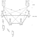
도 1은 본 실시예가 적용될 수 있는 NR 시스템에 대한 구조를 간략하게 도시한 도면이다. 1 is a diagram briefly showing the structure of an NR system to which the present embodiment can be applied.
도 1을 참조하면, NR 시스템은 5GC(5G Core Network)와 NR-RAN파트로 구분되며, NG-RAN은 사용자 평면(SDAP/PDCP/RLC/MAC/PHY) 및 UE(User Equipment)에 대한 제어 평면(RRC) 프로토콜 종단을 제공하는 gNB와 ng-eNB들로 구성된다.gNB 상호 또는 gNB와 ng-eNB는 Xn 인터페이스를 통해 상호 연결된다. gNB와 ng-eNB는 각각 NG 인터페이스를 통해 5GC로 연결된다. 5GC는 단말 접속 및 이동성 제어 기능 등의 제어 평면을 담당하는 AMF (Access and Mobility Management Function)와 사용자 데이터에 제어 기능을 담당하는 UPF (User Plane Function)를 포함하여 구성될 수 있다. NR에서는 6GHz 이하 주파수 대역(FR1, Frequency Range 1)과 6GHz 이상 주파수 대역(FR2, Frequency Range 2)에 대한 지원을 모두 포함한다.Referring to FIG. 1, the NR system is divided into 5GC (5G Core Network) and NR-RAN parts, and NG-RAN is controlled for a user plane (SDAP / PDCP / RLC / MAC / PHY) and user equipment (UE). It consists of gNB and ng-eNBs that provide a plane (RRC) protocol termination. The gNB interconnects or the gNB and ng-eNB are interconnected via an Xn interface. gNB and ng-eNB are each connected to 5GC through an NG interface. The 5GC may include an Access and Mobility Management Function (AMF), which is responsible for a control plane such as a terminal access and mobility control function, and a User Plane Function (UPF), which is a control function for user data. The NR includes support for frequencies below 6 GHz (FR1, Frequency Range 1) and frequencies above 6 GHz (FR2, Frequency Range 2).
gNB는 단말로 NR 사용자 평면 및 제어 평면 프로토콜 종단을 제공하는 기지국을 의미하고, ng-eNB는 단말로 E-UTRA 사용자 평면 및 제어 평면 프로토콜 종단을 제공하는 기지국을 의미한다. 본 명세서에서 기재하는 기지국은 gNB및 ng-eNB를 포괄하는 의미로 이해되어야 하며, 필요에 따라 gNB 또는 ng-eNB를 구분하여 지칭하는 의미로 사용될 수도 있다. gNB means a base station providing NR user plane and control plane protocol termination to the terminal, and ng-eNB means a base station providing E-UTRA user plane and control plane protocol termination to the terminal. The base station described in this specification should be understood as a meaning encompassing gNB and ng-eNB, and may be used in a sense to refer to a gNB or ng-eNB as necessary.
<NR 웨이브 폼,뉴머롤러지 및 프레임 구조><NR wave form, pneumatics and frame structure>
NR에서는 하향링크 전송을 위해서 Cyclic prefix를 사용하는 CP-OFDM 웨이브 폼을 사용하고, 상향링크 전송을 위해서 CP-OFDM 또는 DFT-s-OFDM을 사용한다. OFDM 기술은 MIMO(Multiple Input Multiple Output)와 결합이 용이하며, 높은 주파수 효율과 함께 저 복잡도의 수신기를 사용할 수 있다는 장점을 가지고 있다. In NR, a CP-OFDM waveform using a cyclic prefix is used for downlink transmission, and CP-OFDM or DFT-s-OFDM is used for uplink transmission. OFDM technology is easy to combine with multiple input multiple output (MIMO), and has the advantage of being able to use a low-complexity receiver with high frequency efficiency.
한편, NR에서는 전술한 3가지 시나리오 별로 데이터 속도, 지연속도, 커버리지 등에 대한 요구가 서로 상이하기 때문에 임의의 NR 시스템을 구성하는 주파수 대역을 통해 각각의 시나리오 별 요구사항을 효율적으로 만족시킬 필요가 있다. 이를 위해서, 서로 다른 복수의 뉴머롤러지(numerology) 기반의 무선 자원을 효율적으로 멀티플렉싱(multiplexing)하기 위한 기술이 제안되었다. On the other hand, in the NR, since the demands for data rate, delay rate, and coverage for each of the three scenarios described above are different from each other, it is necessary to efficiently satisfy the requirements for each scenario through a frequency band constituting an arbitrary NR system. . To this end, a technique for efficiently multiplexing a plurality of different numerology-based radio resources has been proposed.
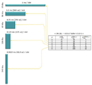
구체적으로, NR 전송 뉴머롤러지는서브캐리어 간격(sub-carrier spacing)과 CP(Cyclic prefix)에 기초하여 결정되며, 아래 표 1과 같이 15khz를 기준으로 ![]()
![]()
![]()
![]()
위 표 1과 같이 NR의 뉴머롤러지는서브캐리어 간격에 따라 5가지로 구분될 수 있다. 이는 4G 통신 기술 중 하나인 LTE의 서브캐리어 간격이 15khz로 고정되는 것과는 차이가 있다. 구체적으로, NR에서 데이터 전송을 위해서 사용되는 서브캐리어 간격은 15, 30, 60, 120khz이고, 동기 신호 전송을 위해서 사용되는 서브캐리어 간격은 15, 30, 12, 240khz이다. 또한, 확장 CP는 60khz 서브캐리어 간격에만 적용된다. 한편, NR에서의 프레임 구조(frame structure)는 1ms의 동일한 길이를 가지는 10의 서브프레임(subframe)으로 구성되는 10ms의 길이를 가지는 프레임(frame)이 정의된다. 하나의 프레임은 5ms의 하프 프레임으로 나뉠 수 있으며, 각 하프 프레임은 5개의 서브프레임을 포함한다. 15khz 서브캐리어 간격의 경우에 하나의 서브프레임은 1개의 슬롯(slot)으로 구성되고, 각 슬롯은 14개의 OFDM 심볼(symbol)로 구성된다. As shown in Table 1 above, the NR numerology can be divided into 5 types according to the subcarrier spacing. This is different from that in which the subcarrier spacing of LTE, which is one of 4G communication technologies, is fixed at 15khz. Specifically, the subcarrier interval used for data transmission in NR is 15, 30, 60, and 120 khz, and the subcarrier interval used for synchronization signal transmission is 15, 30, 12, and 240 khz. In addition, the extended CP applies only to the 60khz subcarrier spacing. On the other hand, the frame structure (frame structure) in the NR is defined as a frame having a length of 10ms composed of 10 subframes (subframe) having the same length of 1ms. One frame can be divided into 5 ms half frames, and each half frame includes 5 subframes. In the case of a 15khz subcarrier interval, one subframe is composed of one slot, and each slot is composed of 14 OFDM symbols.
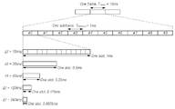
도 2는 본 실시예가 적용될 수 있는 NR 시스템에서의 프레임 구조를 설명하기 위한 도면이다. 2 is a diagram for explaining a frame structure in an NR system to which the present embodiment can be applied.
도 2를 참조하면, 슬롯은 노멀 CP의 경우에 고정적으로 14개의 OFDM 심볼로 구성되나, 슬롯의 길이는 서브캐리어 간격에 따라 달라질 수 있다. 예를 들어, 15khz 서브캐리어 간격을 가지는 뉴머롤러지의 경우에 슬롯은 1ms 길이로 서브프레임과 동일한 길이로 구성된다. 이와 달리, 30khz 서브캐리어 간격을 가지는 뉴머롤러지의 경우에 슬롯은 14개의 OFDM 심볼로 구성되나, 0.5ms의 길이로 하나의 서브프레임에 두 개의 슬롯이 포함될 수 있다. 즉, 서브프레임과 프레임은 고정된 시간 길이를 가지고 정의되며, 슬롯은 심볼의 개수로 정의되어 서브캐리어 간격에 따라 시간 길이가 달라질 수 있다. Referring to FIG. 2, the slot is fixedly composed of 14 OFDM symbols in the case of a normal CP, but the length of the slot may vary depending on the subcarrier interval. For example, in the case of a numerology having a 15 khz subcarrier spacing, the slot is 1 ms long and is configured to have the same length as the subframe. On the contrary, in the case of a neuromerlage having a 30 khz subcarrier spacing, a slot is composed of 14 OFDM symbols, but two slots may be included in one subframe with a length of 0.5 ms. That is, the subframe and the frame are defined with a fixed time length, and the slot is defined by the number of symbols, so that the time length may vary according to the subcarrier interval.
한편, NR은 스케줄링의 기본 단위를 슬롯으로 정의하고, 무선 구간의 전송 지연을 감소시키기 위해서 미니 슬롯(또는 서브 슬롯 또는 non-slot based schedule)도 도입하였다. 넓은 서브캐리어 간격을 사용하면 하나의 슬롯의 길이가 반비례하여 짧아지기 때문에 무선 구간에서의 전송 지연을 줄일 수 있다. 미니 슬롯(또는 서브 슬롯)은 URLLC 시나리오에 대한 효율적인 지원을 위한 것으로 2, 4, 7개 심볼 단위로 스케줄링이 가능하다. Meanwhile, the NR defines a basic unit of scheduling as a slot, and also introduces a mini-slot (or sub-slot or non-slot based schedule) to reduce transmission delay in a radio section. If a wide subcarrier interval is used, the length of one slot is inversely shortened, and thus transmission delay in a wireless section can be reduced. The mini-slot (or sub-slot) is for efficient support for the URLLC scenario and can be scheduled in units of 2, 4, and 7 symbols.
또한, NR은 LTE와 달리 상향링크 및 하향링크 자원 할당을 하나의 슬롯 내에서 심볼 레벨로 정의하였다. HARQ 지연을 줄이기 위해 전송 슬롯 내에서 바로 HARQ ACK/NACK을 송신할 수 있는 슬롯 구조가 정의되었으며, 이러한 슬롯 구조를 자기 포함(self-contained) 구조로 명명하여 설명한다. Also, unlike LTE, uplink and downlink resource allocation is defined as a symbol level within one slot. In order to reduce HARQ delay, a slot structure capable of directly transmitting HARQ ACK / NACK in a transmission slot has been defined, and this slot structure is referred to as a self-contained structure.
NR에서는 총 256개의 슬롯 포맷을 지원할 수 있도록 설계되었으며, 이중 62개의 슬롯 포맷이 Rel-15에서 사용된다. 또한, 다양한 슬롯의 조합을 통해서 FDD 또는 TDD 프레임을 구성하는 공통 프레임 구조를 지원한다. 예를 들어, 슬롯의 심볼이 모두 하향링크로 설정되는 슬롯 구조와 심볼이 모두 상향링크로 설정되는 슬롯 구조 및 하향링크 심볼과 상향링크 심볼이 결합된 슬롯 구조를 지원한다. 또한, NR은 데이터 전송이 하나 이상의 슬롯에 분산되어 스케줄링됨을 지원한다. 따라서, 기지국은 슬롯 포맷 지시자(SFI, Slot Format Indicator)를 이용하여 단말에 슬롯이 하향링크 슬롯인지, 상향링크 슬롯인지 또는 플렉시블 슬롯인지를 알려줄 수 있다. 기지국은 단말 특정하게 RRC 시그널링을 통해서 구성된 테이블의 인덱스를 SFI를 이용하여 지시함으로써 슬롯 포맷을 지시할 수 있으며, DCI(Downlink Control Information)를 통해서 동적으로 지시하거나 RRC를 통해서 정적 또는 준정적으로 지시할 수도 있다. NR is designed to support a total of 256 slot formats, of which 62 slot formats are used in Rel-15. In addition, a common frame structure constituting an FDD or TDD frame is supported through a combination of various slots. For example, a slot structure in which all symbols of a slot are set to downlink, a slot structure in which all symbols are set to uplink, and a slot structure in which downlink symbols and uplink symbols are combined are supported. In addition, NR supports that data transmissions are scheduled to be distributed in one or more slots. Accordingly, the base station can inform the terminal whether the slot is a downlink slot, an uplink slot, or a flexible slot using a slot format indicator (SFI). The base station may indicate the slot format by indicating the index of a table configured through RRC signaling using SFI, and dynamically indicate through DCI (Downlink Control Information) or statically or quasi-statically through RRC. It might be.
<NR 물리 자원 ><NR Physical Resources>
NR에서의 물리 자원(physical resource)과 관련하여, 안테나 포트(antenna port), 자원 그리드(resource grid), 자원 요소(resource element), 자원 블록(resource block), 대역폭 파트(bandwidth part) 등이 고려될 수 있다.With regard to physical resources in NR, antenna ports, resource grids, resource elements, resource blocks, and bandwidth parts are considered. Can be.
안테나 포트는 안테나 포트 상의 심볼이 운반되는 채널이 동일한 안테나 포트 상의 다른 심볼이 운반되는 채널로부터 추론될 수 있도록 정의된다. 하나의 안테나 포트 상의 심볼이 운반되는 채널의 광범위 특성(large-scale property)이 다른 안테나 포트 상의 심볼이 운반되는 채널로부터 추론될 수 있는 경우, 2 개의 안테나 포트는 QC/QCL(quasi co-located 혹은 quasi co-location) 관계에 있다고 할 수 있다. 여기에서, 광범위 특성은 지연 확산(Delay spread), 도플러 확산(Doppler spread), 주파수 시프트(Frequency shift), 평균 수신 파워(Average received power), 수신 타이밍(Received Timing) 중 하나 이상을 포함한다.The antenna port is defined such that a channel carrying a symbol on the antenna port can be inferred from a channel carrying another symbol on the same antenna port. If the large-scale property of a channel carrying a symbol on one antenna port can be inferred from a channel carrying a symbol on another antenna port, the two antenna ports are QC / QCL (quasi co-located or quasi co-location). Here, a wide range of characteristics include one or more of delay spread, doppler spread, frequency shift, average received power, and received timing.
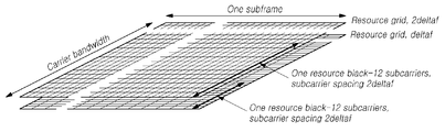
도 3은 본 실시예가 적용될 수 있는 무선 접속 기술이 지원하는 자원 그리드를 설명하기 위한 도면이다. 3 is a diagram for describing a resource grid supported by a radio access technology to which the present embodiment can be applied.
도 3을 참조하면, 자원 그리드(Resource Grid)는 NR이 동일 캐리어에서 복수의 뉴머롤러지를 지원하기 때문에 각 뉴머롤러지에 따라 자원 그리드가 존재할 수 있다. 또한, 자원 그리드는 안테나 포트, 서브캐리어 간격, 전송 방향에 따라 존재할 수 있다. Referring to FIG. 3, a resource grid may exist according to each neuromerging because the NR supports a plurality of neuromerging on the same carrier. In addition, the resource grid may exist according to the antenna port, subcarrier spacing, and transmission direction.
자원 블록(resource block)은 12개의 서브캐리어로 구성되며, 주파수 도메인 상에서만 정의된다. 또한, 자원 요소(resource element)는 1개의 OFDM 심볼과 1개의 서브캐리어로 구성된다. 따라서, 도 3에서와 같이 하나의 자원 블록은 서브캐리어 간격에 따라 그 크기가 달라질 수 있다. 또한, NR에서는 자원 블록 그리드를 위한 공통 참조점 역할을 수행하는 "Point A"와 공통 자원 블록, 가상 자원 블록 등을 정의한다. A resource block is composed of 12 subcarriers and is defined only on the frequency domain. In addition, the resource element (resource element) is composed of one OFDM symbol and one subcarrier. Therefore, as shown in FIG. 3, the size of one resource block may vary according to the subcarrier interval. In addition, in NR, "Point A" serving as a common reference point for the resource block grid, a common resource block, and a virtual resource block are defined.
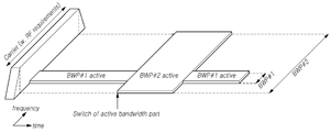
도 4는 본 실시예가 적용될 수 있는 무선 접속 기술이 지원하는 대역폭 파트를 설명하기 위한 도면이다. 4 is a diagram for describing a bandwidth part supported by a radio access technology to which the present embodiment can be applied.
NR에서는 캐리어 대역폭이 20Mhz로 고정된 LTE와 달리 서브캐리어 간격 별로 최대 캐리어 대역폭이 50Mhz에서 400Mhz로 설정된다. 따라서, 모든 단말이 이러한 캐리어 대역폭을 모두 사용하는 것을 가정하지 않는다. 이에 따라서 NR에서는 도 4에 도시된 바와 같이 캐리어 대역폭 내에서 대역폭 파트를 지정하여 단말이 사용할 수 있다. 또한, 대역폭 파트는 하나의 뉴머롤러지와 연계되며 연속적인 공통 자원 블록의 서브 셋으로 구성되고, 시간에 따라 동적으로 활성화 될 수 있다. 단말에는 상향링크 및 하향링크 각각 최대 4개의 대역폭 파트가 구성되고, 주어진 시간에 활성화된 대역폭 파트를 이용하여 데이터가 송수신된다. Unlike LTE, where the carrier bandwidth is fixed at 20Mhz in NR, the maximum carrier bandwidth is set from 50Mhz to 400Mhz for each subcarrier interval. Therefore, it is not assumed that all terminals use all of these carrier bandwidths. Accordingly, in NR, as shown in FIG. 4, a terminal can be used by designating a bandwidth part within a carrier bandwidth. In addition, the bandwidth part is associated with one neurology and is composed of a subset of consecutive common resource blocks, and can be dynamically activated with time. A maximum of 4 bandwidth parts are configured in the uplink and downlink, respectively, and data is transmitted and received using the bandwidth part activated at a given time.
페어드 스펙트럼(paired spectrum)의 경우 상향링크 및 하향링크 대역폭 파트가 독립적으로 설정되며, 언페어드 스펙트럼(unpaired spectrum)의 경우 하향링크와 상향링크 동작 간에 불필요한 주파수 리튜닝(re-tunning)을 방지하기 위해서 하향링크와 상향링크의 대역폭 파트가 중심 주파수를 공유할 수 있도록 쌍을 이루어 설정된다.In the case of a paired spectrum, the uplink and downlink bandwidth parts are independently set, and in the case of an unpaired spectrum, unnecessary frequency re-tunning is prevented between downlink and uplink operation. In order to achieve this, the bandwidth part of the downlink and uplink is set in pairs so that the center frequency can be shared.
<NR 초기 접속><NR initial connection>
NR에서 단말은 기지국에 접속하여 통신을 수행하기 위해서 셀 검색 및 랜덤 액세스 절차를 수행한다. In NR, a terminal accesses a base station and performs a cell search and random access procedure to perform communication.
셀 검색은 기지국이 전송하는 동기 신호 블록(SSB, Synchronization Signal Block)를 이용하여 단말이 해당 기지국의 셀에 동기를 맞추고, 물리계층 셀 ID를 획득하며, 시스템 정보를 획득하는 절차이다. Cell search is a procedure in which a terminal synchronizes with a cell of a corresponding base station, acquires a physical layer cell ID, and acquires system information using a synchronization signal block (SSB) transmitted by the base station.
도 5는 본 실시예가 적용될 수 있는 무선 접속 기술에서의 동기 신호 블록을 예시적으로 도시한 도면이다. 5 exemplarily shows a synchronization signal block in a radio access technology to which the present embodiment can be applied.
도 5를 참조하면, SSB는 각각 1개 심볼 및 127개 서브 캐리어를 점유하는 PSS(primarysynchronization signal) 및 SSS(secondary synchronization signal) 및 3개의 OFDM 심볼 및 240 개의 서브캐리어에 걸쳐있는 PBCH로 구성된다. Referring to FIG. 5, the SSB is composed of a primary synchronization signal (PSS) and a secondary synchronization signal (SSS) and three OFDM symbols occupying one symbol and 127 subcarriers, respectively, and a PBCH spanning 240 subcarriers.
단말은 시간 및 주파수 도메인에서 SSB를 모니터링하여 SSB를 수신한다. The UE receives the SSB by monitoring the SSB in the time and frequency domain.
SSB는 5ms 동안 최대 64번 전송될 수 있다. 다수의 SSB는 5ms 시간 내에서 서로 다른 전송 빔으로 전송되며, 단말은 전송에 사용되는 특정 하나의 빔을 기준으로 볼 때에는 20ms의 주기마다 SSB가 전송된다고 가정하고 검출을 수행한다. 5ms 시간 내에서 SSB 전송에 사용할 수 있는 빔의 개수는 주파수 대역이 높을수록 증가할 수 있다. 예를 들어, 3GHz 이하에서는 최대 4개의 SSB 빔 전송이 가능하며, 3~6GHz까지의 주파수 대역에서는 최대 8개, 6GHz 이상의 주파수 대역에서는 최대 64개의 서로 다른 빔을 사용하여 SSB를 전송할 수 있다. SSB can be transmitted up to 64 times in 5 ms. Multiple SSBs are transmitted in different transmission beams within a 5 ms time period, and the UE performs detection by assuming that SSBs are transmitted every 20 ms periods based on a specific one beam used for transmission. The number of beams that can be used for SSB transmission within 5 ms time may increase as the frequency band increases. For example, up to 4 SSB beams can be transmitted at 3 GHz or less, and up to 8 SSBs can be transmitted using up to 8 different beams in the frequency band from 3 to 6 GHz and up to 64 in the frequency band above 6 GHz.
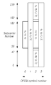
SSB는 하나의 슬롯에 두 개가 포함되며, 서브캐리어 간격에 따라 아래와 같이 슬롯 내에서의 시작 심볼과 반복 횟수가 결정된다.Two SSBs are included in one slot, and the starting symbol and the number of repetitions in the slot are determined according to the subcarrier interval.
한편, SSB는 종래 LTE의 SS와 달리 캐리어 대역폭의 센터 주파수에서 전송되지 않는다. 즉, SSB는 시스템 대역의 중심이 아닌 곳에서도 전송될 수 있고, 광대역 운영을 지원하는 경우 주파수 도메인 상에서 복수의 SSB가 전송될 수 있다. 이에 따라서, 단말은 SSB를 모니터링 하는 후보 주파수 위치인 동기 래스터(synchronization raster)를 이용하여 SSB를 모니터링 한다. 초기 접속을 위한 채널의 중심 주파수 위치 정보인 캐리어래스터(carrier raster)와 동기 래스터는 NR에서 새롭게 정의되었으며, 동기 래스터는 캐리어래스터에 비해서, 주파수 간격이 넓게 설정되어 있어서, 단말의 빠른 SSB 검색을 지원할 수 있다. On the other hand, SSB is not transmitted at the center frequency of the carrier bandwidth, unlike the SS of the conventional LTE. That is, the SSB may be transmitted out of the center of the system band, and when supporting broadband operation, a plurality of SSBs may be transmitted on the frequency domain. Accordingly, the terminal monitors the SSB using a synchronization raster, which is a candidate frequency location for monitoring the SSB. The carrier raster and the synchronization raster, which are the center frequency location information of the channel for initial access, are newly defined in the NR, and the synchronization raster has a wider frequency interval than the carrier raster, and thus supports fast SSB search of the UE. Can be.
단말은 SSB의 PBCH를 통해서 MIB를 획득할 수 있다. MIB(Master Information Block)는 단말이 네트워크가 브로드캐스팅 하는 나머지 시스템 정보(RMSI, Remaining Minimum System Information)를 수신하기 위한 최소 정보를 포함한다. 또한, PBCH는 시간 도메인 상에서의 첫 번째 DM-RS 심볼의 위치에 대한 정보, SIB1을 단말이 모니터링하기 위한 정보(예를 들어, SIB1 뉴머롤러지 정보, SIB1 CORESET에 관련된 정보, 검색 공간 정보, PDCCH 관련 파라미터 정보 등), 공통 자원 블록과 SSB 사이의 오프셋 정보(캐리어 내에서의 절대 SSB의 위치는 SIB1을 통해서 전송) 등을 포함할 수 있다. 여기서, SIB1 뉴머롤러지 정보는 단말이 셀 검색 절차를 완료한 이후에 기지국에 접속하기 위한 랜덤 액세스 절차의 메시지 2와 메시지 4에서도 동일하게 적용된다. The terminal may acquire MIB through the PBCH of the SSB. The MIB (Master Information Block) includes minimum information for the terminal to receive the remaining system information (RMSI, Remaining Minimum System Information) broadcast by the network. In addition, PBCH is information on the location of the first DM-RS symbol on the time domain, information for the UE to monitor SIB1 (for example, SIB1 neuromerging information, information related to SIB1 CORESET, search space information, PDCCH Related parameter information, etc.), offset information between the common resource block and the SSB (the position of the absolute SSB in the carrier is transmitted through SIB1), and the like. Here, the SIB1 pneumatic information is equally applied to
전술한 RMSI는 SIB1(System Information Block 1)을 의미하며, SIB1은 셀에서 주기적으로(ex, 160ms) 브로드캐스팅 된다. SIB1은 단말이 초기 랜덤 액세스 절차를 수행하는데 필요한 정보를 포함하며, PDSCH를 통해서 주기적으로 전송된다. 단말이 SIB1을 수신하기 위해서는 PBCH를 통해서 SIB1 전송에 사용되는 뉴머롤러지 정보, SIB1의 스케줄링에 사용되는 CORESET(Control Resource Set) 정보를 수신해야 한다. 단말은 CORESET 내에서 SI-RNTI를 이용하여 SIB1에 대한 스케줄링 정보를 확인하고, 스케줄링 정보에 따라 SIB1을 PDSCH 상에서 획득한다. SIB1을 제외한 나머지 SIB들은 주기적으로 전송될 수도 있고, 단말의 요구에 따라 전송될 수도 있다. The aforementioned RMSI means System Information Block 1 (SIB1), and SIB1 is broadcast periodically (ex, 160 ms) in a cell. SIB1 includes information necessary for the UE to perform the initial random access procedure, and is periodically transmitted through the PDSCH. In order to receive SIB1, the UE must receive pneumatic information used for SIB1 transmission and control resource set (CORESET) information used for scheduling of SIB1 through the PBCH. The UE checks scheduling information for SIB1 using SI-RNTI in CORESET, and acquires SIB1 on the PDSCH according to the scheduling information. SIBs other than SIB1 may be periodically transmitted or may be transmitted according to a terminal request.
도 6는 본 실시예가 적용될 수 있는 무선 접속 기술에서의 랜덤 액세스 절차를 설명하기 위한 도면이다. 6 is a diagram for explaining a random access procedure in a radio access technology to which the present embodiment can be applied.
도 6을 참조하면, 셀 검색이 완료되면 단말은 기지국으로 랜덤 액세스를 위한 랜덤 액세스 프리앰블을 전송한다. 랜덤 액세스 프리앰블은 PRACH를 통해서 전송된다. 구체적으로, 랜덤 액세스 프리앰블은 주기적으로 반복되는 특정 슬롯에서 연속된 무선 자원으로 구성되는 PRACH를 통해서 기지국으로 전송된다. 일반적으로, 단말이 셀에 초기 접속하는 경우에 경쟁 기반 랜덤 액세스 절차를 수행되며, 빔 실패 복구(BFR, Beam Failure Recovery)를 위해서 랜덤 액세스를 수행하는 경우에는 비경쟁 기반 랜덤 액세스 절차가 수행된다. Referring to FIG. 6, when cell search is completed, the UE transmits a random access preamble for random access to the base station. The random access preamble is transmitted through PRACH. Specifically, the random access preamble is transmitted to the base station through PRACH composed of continuous radio resources in a specific slot that is periodically repeated. In general, a contention-based random access procedure is performed when the UE initially accesses a cell, and a non-competition-based random access procedure is performed when random access is performed for beam failure recovery (BFR).
단말은 전송한 랜덤 액세스 프리앰블에 대한 랜덤 액세스 응답을 수신한다. 랜덤 액세스 응답에는 랜덤 액세스 프리앰블식별자(ID), UL Grant (상향링크 무선자원), 임시 C-RNTI(Temporary Cell - Radio Network Temporary Identifier) 그리고 TAC(Time Alignment Command) 이 포함될 수 있다. 하나의 랜덤 액세스 응답에는 하나 이상의 단말들을 위한 랜덤 액세스 응답 정보가 포함될 수 있기 때문에, 랜덤 액세스 프리앰블식별자는 포함된 UL Grant, 임시 C-RNTI 그리고 TAC가 어느 단말에게 유효한지를 알려주기 위하여 포함될 수 있다. 랜덤 액세스 프리앰블식별자는 기지국이 수신한 랜덤 액세스 프리앰블에 대한식별자일 수 있다. TAC는 단말이 상향 링크 동기를 조정하기 위한 정보로서 포함될 수 있다. 랜덤 액세스 응답은 PDCCH상의 랜덤 액세스 식별자, 즉 RA-RNTI(Random Access - Radio Network Temporary Identifier)에 의해지시될 수 있다.The terminal receives a random access response to the transmitted random access preamble. The random access response may include a random access preamble identifier (ID), UL grant (uplink radio resource), temporary C-RNTI (Temporary Cell-Radio Network Temporary Identifier) and TAC (Time Alignment Command). Since one random access response may include random access response information for one or more terminals, a random access preamble identifier may be included to inform which terminal the included UL Grant, temporary C-RNTI, and TAC are valid. The random access preamble identifier may be an identifier for the random access preamble received by the base station. The TAC may be included as information for the UE to adjust uplink synchronization. The random access response may be indicated by a random access identifier on the PDCCH, that is, a Random Access-Radio Network Temporary Identifier (RA-RNTI).
유효한 랜덤 액세스 응답을 수신한 단말은 랜덤 액세스 응답에 포함된 정보를 처리하고, 기지국으로스케줄링된 전송을 수행한다. 예를 들어, 단말은 TAC을 적용시키고, 임시 C-RNTI를 저장한다. 또한, UL Grant를 이용하여, 단말의 버퍼에 저장된 데이터 또는 새롭게 생성된 데이터를 기지국으로 전송한다. 이 경우 단말을 식별할 수 있는 정보가 포함되어야 한다.Upon receiving a valid random access response, the terminal processes the information included in the random access response, and performs scheduled transmission to the base station. For example, the UE applies TAC and stores a temporary C-RNTI. In addition, by using UL Grant, data stored in the buffer of the terminal or newly generated data is transmitted to the base station. In this case, information capable of identifying the terminal should be included.
마지막으로 단말은 경쟁 해소를 위한 하향링크 메시지를 수신한다.Finally, the terminal receives a downlink message for contention resolution.
<NR CORESET><NR CORESET>
NR에서의 하향링크 제어채널은 1~3 심볼의 길이를 가지는 CORESET(Control Resource Set)에서 전송되며, 상/하향 스케줄링 정보와 SFI(Slot format Index), TPC(Transmit Power Control) 정보 등을 전송한다. The downlink control channel in the NR is transmitted in a control resource set (CORESET) having a length of 1 to 3 symbols, and transmits up / down scheduling information, slot format index (SFI), and transmit power control (TPC) information. .
이와 같이 NR에서는 시스템의 유연성을 확보하기 위해서, CORESET 개념을 도입하였다. CORESET(Control Resource Set)은 하향링크 제어 신호를 위한 시간-주파수 자원을 의미한다. 단말은 CORESET 시간-주파수 자원에서 하나 이상의 검색 공간을 사용하여 제어 채널 후보를 디코딩할 수 있다. CORESET 별 QCL(Quasi CoLocation) 가정을 설정하였으며, 이는 종래 QCL에 의해서 가정되는 특성인 지연 스프레드, 도플러 스프레드, 도플러 쉬프트, 평균 지연 외에 아날로그 빔 방향에 대한 특성을 알리기 위한 목적으로 사용된다. Thus, in order to secure the flexibility of the system, NR introduced the concept of CORESET. CORESET (Control Resource Set) means a time-frequency resource for a downlink control signal. The UE may decode the control channel candidate using one or more search spaces in the CORESET time-frequency resource. QCL (Quasi CoLocation) assumptions for each CORESET were established, and this is used to inform the characteristics of the analog beam direction in addition to delay spread, Doppler spread, Doppler shift, and average delay, which are characteristics assumed by the conventional QCL.
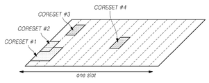
도 7은 CORESET에 대해서 설명하기 위한 도면이다. 7 is a view for explaining CORESET.
도 7을 참조하면, CORESET은 하나의 슬롯 내에서 캐리어 대역폭 내에서 다양한 형태로 존재할 수 있으며, 시간 도메인 상에서 CORESET은 최대 3개의 OFDM 심볼로 구성될 수 있다. 또한, CORESET은 주파수 도메인 상에서 캐리어 대역폭까지 6개의 자원 블록의 배수로 정의된다. Referring to FIG. 7, CORESET may exist in various forms within a carrier bandwidth within one slot, and CORESET may consist of up to 3 OFDM symbols in a time domain. In addition, CORESET is defined as a multiple of 6 resource blocks from the frequency domain to the carrier bandwidth.
첫 번째 CORESET은 네트워크로부터 추가 구성 정보 및 시스템 정보를 수신할 수 있도록 초기 대역폭 파트 구성의 일부로 MIB를 통해서 지시된다. 기지국과의 연결 설정 후에 단말은 RRC 시그널링을 통해서 하나 이상의 CORESET 정보를 수신하여 구성할 수 있다.The first CORESET is indicated through the MIB as part of the initial bandwidth part configuration to receive additional configuration information and system information from the network. After establishing a connection with the base station, the terminal may receive and configure one or more CORESET information through RRC signaling.
본 명세서에서 NR(New Radio)과 관련한 주파수, 프레임, 서브프레임, 자원, 자원블럭, 영역(region), 밴드, 서브밴드, 제어채널, 데이터채널, 동기신호, 각종 참조신호, 각종 신호, 각종 메시지는 과거 또는 현재 사용되는 의미 또는 장래 사용되는 다양한 의미로 해석될 수 있다.In this specification, frequency, frame, subframe, resource, resource block, region, band, subband, control channel, data channel, synchronization signal, various reference signals, various signals, various messages related to NR (New Radio) Can be interpreted as meaning used in the past or present or various meanings used in the future.
[5G NR(New Rat)] [5G NR (New Rat)]
3GPP는 최근 차세대/5G 무선 액세스 기술에 대한 연구를 위한 study item인 “Study on New Radio Access Technology”를 승인하고, 이를 기반으로 RAN WG1에서는 각각 NR(New Radio)를 위한 frame structure, channel coding & modulation, waveform & multiple access scheme 등에 대한 논의가 시작되었다. NR은 LTE 대비 향상된 데이터 전송율 뿐 아니라, 세분화되고 구체화된 usage scenario 별로 요구되는 다양한 QoS requirements를 만족시킬 수 있는 설계가 이루어지도록 요구되고 있다. 특히 NR의 대표적 usage scenario로서 eMBB(enhancement Mobile BroadBand), mMTC(massive MTC) 및 URLLC(Ultra Reliable and Low Latency Communications)가 정의되었으며, 각각의 usage scenario별 requirements를 만족하기 위한 방법으로서 LTE 대비 flexible한 frame structure 설계가 요구되고 있다. 각각의 usage scenario는 data rates, latency, reliability, coverage 등에 대한 requirements가 서로 상이하기 때문에 임의의 NR 시스템을 구성하는 주파수 대역을 통해 각각의 usage scenario 별 requirements를 효율적으로 만족시키기 위한 방법으로서 서로 다른 numerology(e.g. subcarrier spacing, subframe, TTI, etc.) 기반의 무선 자원 유닛(unit)을 효율적으로 multiplexing하는 방안에 대한 필요성이 제기되고 있다. 3GPP recently approved “Study on New Radio Access Technology”, a study item for research on next-generation / 5G radio access technology, and based on this, RAN WG1 has a frame structure, channel coding & modulation for NR (New Radio), respectively. , waveform & multiple access scheme, etc. started. NR is required to be designed to satisfy various QoS requirements required for each segmented and specific usage scenario, as well as an improved data rate compared to LTE. In particular, as a representative usage scenario of NR, enhancement mobile BroadBand (eMBB), massive MTC (mMTC) and Ultra Reliable and Low Latency Communications (URLLC) have been defined, and a flexible frame compared to LTE as a method to satisfy the requirements for each usage scenario. Structure design is required. Because each usage scenario has different requirements for data rates, latency, reliability, coverage, etc., different numerology (as a method for efficiently satisfying requirements for each usage scenario through a frequency band constituting an arbitrary NR system) For example, there is a need for a method of efficiently multiplexing radio resource units based on subcarrier spacing, subframe, TTI, etc.).
이를 위한 한 방법으로서, 서로 다른 subcarrier spacing값을 갖는 numerology에 대해 하나 혹은 복수의 NR component carrier(s)를 통해 TDM, FDM 혹은 TDM/FDM 기반으로 다중화하여 지원하는 방법 및 time domain에서의 스케줄링 단위를 구성함에 있어서 하나 이상의 time unit을 지원하는 방안에 대한 논의가 이루어졌다. 이와 관련하여 NR에서는 time domain structure의 한 종류로서 subframe에 대한 정의가 이루어졌으며, 해당 subframe duration을 정의하기 위한 reference numerology로서 LTE와 동일한 15kHz SCS(Sub-Carrier Spacing) 기반 normal CP overhead의 14개의 OFDM symbols로 구성된 단일한 subframe duration을 정의하기로 결정하였다. 이에 따라 NR에서 subframe은 1ms의 time duration을 가진다. 단, LTE와 달리 NR의 subframe은 절대적인 reference time duration으로서, 실제 상/하향 링크 데이터 스케줄링의 기반의 되는 time unit으로서 slot 및 mini-slot이 정의될 수 있다. 이 경우, 해당 slot을 구성하는 OFDM 심볼의 개수, y값은 up to 60kHz의 SCS값을 갖는 numerology에 대해 y=7 and 14으로 정의되고, 60kHz보다 큰 SCS값을 갖는 numerology의 경우 y=14의 값을 갖도록 결정되었다.As a method for this, a method of multiplexing and supporting scheduling units in a time domain and TDM, FDM, or TDM / FDM based on one or multiple NR component carriers for numerology having different subcarrier spacing values Discussion on how to support more than one time unit in the construction was made. In this regard, in NR, a subframe is defined as a type of time domain structure, and 14 OFDM symbols of normal CP overhead based on 15kHz SCS (Sub-Carrier Spacing), which is the same as LTE as a reference numerology for defining the subframe duration. It was decided to define a single subframe duration consisting of. Accordingly, the subframe in NR has a time duration of 1 ms. However, unlike LTE, the subframe of NR is an absolute reference time duration, and slots and mini-slots may be defined as time units based on actual uplink / downlink data scheduling. In this case, the number of OFDM symbols constituting the slot and the y value are defined as y = 7 and 14 for numerology having an SCS value of up to 60 kHz, and y = 14 for numerology having an SCS value greater than 60 kHz. It was decided to have a value.
이에 따라 임의의 slot은 7개 혹은 14개의 심볼로 구성될 수 있으며, 또한 해당 slot의 transmission direction에 따라 모든 심볼이 DL transmission을 위해 이용되거나, 혹은 모든 심볼이 UL transmission을 위해 이용되거나, 혹은 DL portion + (gap) + UL portion의 형태로 이용될 수 있다.Accordingly, an arbitrary slot may be composed of 7 or 14 symbols, and all symbols may be used for DL transmission, or all symbols may be used for UL transmission, or DL portion depending on the transmission direction of the slot. + (gap) + UL portion.
또한 임의의 numerology(혹은 SCS)에서 해당 slot보다 적은 수의 심볼로 구성된 mini-slot이 정의되어 이를 기반으로 상/하향 링크 데이터 송수신을 위한 짧은 길이의 time-domain scheduling interval이 설정되거나, 혹은 slot aggregation을 통해 상/하향 링크 데이터 송수신을 위한 긴 길이의 time-domain scheduling interval이 구성될 수 있다. 특히 URLLC와 같이 latency critical한 데이터에 대한 송수신의 경우, 15kHz와 같이 SCS값이 작은 numerology 기반의 frame 구조에서 정의된 0.5ms(7 symbols) 혹은 1ms(14 symbols) 기반의 slot 단위로 스케줄링이 이루어질 경우, latency requirement를 만족시키기 힘들 수 있기 때문에 이를 위해서 해당 slot보다 적은 수의 OFDM 심볼로 구성된 mini-slot을 정의하여 이를 기반으로 해당 URLLC와 같은 latency critical한 데이터에 대한 스케줄링이 이루어지도록 정의할 수 있다. In addition, in a certain numerology (or SCS), a mini-slot consisting of fewer symbols than the corresponding slot is defined, and based on this, a short length time-domain scheduling interval for transmitting / receiving uplink / downlink data is established, or slot aggregation Through this, a long-length time-domain scheduling interval for transmitting / receiving uplink / downlink data may be configured. In particular, in the case of transmission / reception of latency critical data such as URLLC, when scheduling is performed in a slot unit based on 0.5 ms (7 symbols) or 1 ms (14 symbols) defined in a numerology-based frame structure having a small SCS value such as 15 kHz. In order to achieve this, it may be difficult to satisfy the latency requirement, so for this, a mini-slot consisting of fewer OFDM symbols than the corresponding slot can be defined to define scheduling for latency critical data such as the corresponding URLLC.
또는 상기에서 서술한 바와 같이 하나의 NR Carrier 내에서 서로 다른 SCS값을 갖는 numerology를 TDM and/or FDM 방식으로 다중화하여 지원함으로써, 각각의 numerology 별로 정의된 slot(혹은 mini-slot) length를 기반으로 latency requirement에 맞추어 데이터를 스케줄링하는 방안도 고려되고 있다. 예를 들어 아래의 도 8과 같이 SCS가 60kHz인 경우, SCS 15kHz인 경우보다 심볼 길이가 1/4정도로 줄어들기 때문에 동일하게 7개의 OFDM 심볼로 하나의 slot을 구성할 경우, 해당 15kHz 기반의 slot length는 0.5ms이 되는 반면, 60kHz 기반의 slot length는 약 0.125ms으로 줄어들게 된다.Alternatively, as described above, by supporting multiplexing of numerology with different SCS values in one NR carrier by TDM and / or FDM method, based on the slot (or mini-slot) length defined for each numerology. A method of scheduling data according to latency requirements is also being considered. For example, as shown in FIG. 8 below, when the SCS is 60 kHz, since the symbol length is reduced to about 1/4 compared to the case of the
이처럼 NR에서는 서로 다른 SCS 혹은 서로 다른 TTI length를 정의함으로써, URLLC와 eMBB 각각의 requirement를 만족시키는 방법에 대한 논의가 진행되고 있다.In this way, NR defines different SCS or different TTI lengths to discuss how to satisfy URLLC and eMBB requirements.
[BWP (bandwidth part)][BWP (bandwidth part)]
기존 LTE system의 경우, 임의의 LTE CC(Component Carrier)에 대한 scalable bandwidth operation을 지원하였다. 즉, 주파수 deployment scenario에 따라 임의의 LTE 사업자는 하나의 LTE CC를 구성함에 있어서, 최소 1.4 MHz부터 최대 20 MHz의 대역폭을 구성할 수 있었고, normal LTE 단말은 하나의 LTE CC에 대해 20 MHz bandwidth의 송수신 capability를 지원하였다. In the case of the existing LTE system, it supports scalable bandwidth operation for any LTE component carrier (CC). That is, according to the frequency deployment scenario, any LTE operator can configure a single LTE CC to configure a minimum bandwidth of 1.4 MHz to a maximum of 20 MHz, and the normal LTE terminal has a 20 MHz bandwidth of one LTE CC. Transceiver capability was supported.
하지만, NR의 경우, 하나의 wideband NR CC를 통해 서로 다른 송수신 bandwidth capability를 갖는 NR 단말에 대한 지원이 가능하도록 그 설계가 이루어지고 있으며, 이에 따라 아래의 도 9와 같이 임의의 NR CC에 대해 세분화된 대역폭으로 구성된 하나 이상의 bandwidth part(s)를 구성하여, 단말 별로 서로 다른 bandwidth part configuration 및 activation을 통해 flexible한 wider bandwidth operation을 지원하도록 요구되고 있다. However, in the case of NR, the design is made to support NR terminals having different transmission / reception bandwidth capabilities through one wideband NR CC, and thus is subdivided into arbitrary NR CCs as shown in FIG. 9 below. It is required to support flexible wider bandwidth operation through different bandwidth part configuration and activation for each terminal by configuring one or more bandwidth part (s) composed of the configured bandwidth.
구체적으로 NR에서는 단말 관점에서 구성된 하나의 serving cell을 통해 하나 이상의 bandwidth part를 구성할 수 있으며, 해당 단말은 해당 serving cell에서 하나의 DL bandwidth part와 하나의 UL bandwidth part를 activation하여 상/하향 링크 데이터 송수신을 위해 사용하도록 정의되었다. 또한 해당 단말에서 복수의 serving cell이 설정된 경우, 즉 CA이 적용된 단말에 대해서도 각각의 serving cell 별로 하나의 DL bandwidth part 그리고/혹은 UL bandwidth part를 activation하여 해당 serving cell의 무선 자원을 이용하여 상/하향 링크 데이터 송수신을 위해 사용하도록 정의되었다.Specifically, in the NR, one or more bandwidth parts can be configured through one serving cell configured from the viewpoint of the terminal, and the corresponding terminal activates one DL bandwidth part and one UL bandwidth part in the serving cell, thereby uplink / downlink data. It is defined to be used for transmission and reception. In addition, when a plurality of serving cells are configured in the corresponding terminal, that is, for a terminal to which CA is applied, one DL bandwidth part and / or UL bandwidth part is activated for each serving cell, and uplink / downlink is performed using radio resources of the corresponding serving cell. It is defined to be used for transmitting and receiving link data.
구체적으로 임의의 serving cell에서 단말의 initial access procedure를 위한 initial bandwidth part가 정의되며, 각각의 단말 별로 dedicated RRC signaling을 통해 하나 이상의 UE-specific bandwidth part(s)가 구성되고, 또한 각각의 단말 별로 fallback operation을 위한 default bandwidth part가 정의될 수 있다.Specifically, an initial bandwidth part for an initial access procedure of a terminal is defined in an arbitrary serving cell, and one or more UE-specific bandwidth part (s) is configured through dedicated RRC signaling for each terminal, and also fallback for each terminal The default bandwidth part for operation can be defined.
단, 임의의 serving cell에서 단말의 capability 및 bandwidth part(s) 구성에 따라 동시에 복수의 DL and/or UL bandwidth parts를 activation하여 사용하도록 정의할 수 있으나, NR rel-15에서는 임의의 단말에서 임의의 시간에 하나의 DL bandwidth part 및 UL bandwidth part만을 activation하여 사용하도록 정의되었다.However, it can be defined to activate and use a plurality of DL and / or UL bandwidth parts at the same time according to the capability and bandwidth part (s) configuration of the terminal in any serving cell, but in NR rel-15, any terminal can use It was defined to activate and use only one DL bandwidth part and UL bandwidth part at a time.
[LTE sidelink][LTE sidelink]
기존의 LTE 시스템에서는 단말 간 직접 통신 및 V2X(특히 V2V) 서비스 제공을 위해 단말 간 direct link, 즉, sidelink 송수신을 위한 무선 채널 및 무선 프로토콜 설계가 이루어졌다. 이와 관련하여, 무선 sidelink 송신단과 수신단 간의 동기화를 위한 동기 신호인 PSSS/SSSS 및 이와 관련한 sidelink MIB(Master Information Block) 송수신을 위한 PSBCH(Physical Sidelink Broadcasting Channel)이 정의되었고, 또한 discovery 정보 송수신을 위한 PSDCH(Physical Sidelink Discovery channel), SCI(Sidelink Control Information) 송수신을 위한 PSCCH(Physical Sidelink Control Channel), sidelink 데이터 송수신을 위한 PSSCH(Physical Sidelink Shared Channel)에 대한 설계가 이루어졌다. In the existing LTE system, a direct channel between terminals to provide direct communication between terminals and V2X (especially V2V) service, that is, design of a radio channel and radio protocol for sidelink transmission / reception. In this regard, a PSSS / SSSS that is a synchronization signal for synchronization between a wireless sidelink transmitting end and a receiving end and a PSBCH (Physical Sidelink Broadcasting Channel) for transmitting and receiving a sidelink Master Information Block (MIB) have been defined, and PSDCH for transmitting and receiving discovery information. (Physical Sidelink Discovery channel), PSCCH (Physical Sidelink Control Channel) for transmitting and receiving Sidelink Control Information (SCI), and PSSCH (Physical Sidelink Shared Channel) for transmitting and receiving sidelink data were made.
기존 V2X sidelink에서는 Broadcast관련 전송만 존재하였다. 5G NR V2X에서는 신규 기술로 Groupcast, unicast가 새롭게 도입되었다. 따라서 Groupcast/Unicast 전송에 대한 전송 링크 관리 방법을 현재 Rel-16에서 논의하고 있다. In the existing V2X sidelink, only broadcast-related transmission existed. In 5G NR V2X, Groupcast and unicast are newly introduced as new technologies. Therefore, the transmission link management method for Groupcast / Unicast transmission is currently being discussed in Rel-16.
본 발명은 차세대/5G NR V2X 서비스를 제공하기 위한 단말 간 무선 링크인, NR sidelink운용을 위한 CQI 관리 방법에 대해서 기술한다. 특히 Groupcast sidelink 통신을 위해서 scheduling UE와 scheduled UE들 사이의 CQI 추정 및 HARQ 프로시저 설계에 대한 구체적인 방법을 기술한다.The present invention describes a CQI management method for NR sidelink operation, which is a wireless link between terminals for providing a next generation / 5G NR V2X service. In particular, a specific method for CQI estimation and HARQ procedure design between scheduling UE and scheduled UEs for Groupcast sidelink communication is described.
현재 NR V2X에서는 sidelink 설계를 새롭게 진행하고 있다. 즉 기존 LTE sidelink에서 지원했던 Broadcast이외에 Unicast/Groupcast를 새롭게 도입하기로 결정하였다.Currently, NR V2X is undergoing a new sidelink design. That is, it was decided to introduce a new Unicast / Groupcast in addition to the broadcast supported by the existing LTE sidelink.
또한 Groupcast역시 Unicast와 마찬가지로 sidelink HARQ 피드백을 지원하기로 결정하였다.In addition, Groupcast also decided to support sidelink HARQ feedback like Unicast.
아래는 RAN1#94bis회의에서 관련 결정 사항이다. Below are the relevant decisions at the RAN1 # 94bis meeting.
Agreements:Agreements:
· For unicast, sidelink HARQ feedback and HARQ combining in the physical layer are supported.· For unicast, sidelink HARQ feedback and HARQ combining in the physical layer are supported.
o FFS details, including the possibility of disabling HARQ in some scenarioso FFS details, including the possibility of disabling HARQ in some scenarios
· For groupcast, sidelink HARQ feedback and HARQ combining in the physical layer are supported.· For groupcast, sidelink HARQ feedback and HARQ combining in the physical layer are supported.
o FFS details, including the possibility of disabling HARQ in some scenarioso FFS details, including the possibility of disabling HARQ in some scenarios
이하에서는 앞서 기술한 V2X sidelink Groupcast 관련 CQI 관리 방법에 대해서 제안한다. 본 발명의 제안은 크게 두 가지 카테고리를 포함한다. Groupcast로 설정된 scheduled UE들의 'CSI 추정 및 리포팅 방법'과 'HARQ 피드백 전송 방법' 에 대한 제안을 포함한다.Hereinafter, a method for managing CQI related to V2X sidelink Groupcast described above is proposed. The proposal of the present invention broadly includes two categories. Includes proposals for 'CSI estimation and reporting method' and 'HARQ feedback transmission method' of scheduled UEs configured with Groupcast.
방안 1. Scheduling UE는 Groupcast로 설정된 scheduled UE들의 CSI를 기반으로 특정 UE(s)만을 선택하여 CSI 리포팅 수행하도록 설정할 수 있다.
본 제안에서는 V2X의 sidelink 통신 중 Group-cast에 대한 Scheduling UE, Scheduled UE에 대한 무선 링크 관리 방법에 대해서 제안한다. In this proposal, we propose a method for managing a radio link for Scheduling UE and Scheduled UE for Group-cast during sidelink communication of V2X.
* Scheduling UE: 전체 Group으로 설정된 sidelink에서 기존의 gNB와 같은 역할을 수행하는 단말을 의미* Scheduling UE: means a terminal that performs the same role as an existing gNB in a sidelink set as an entire group
* Scheduled UE(s): Scheduling UE로부터 제어를 받는 group 내 타 UE를 Scheduled UE라고 지칭* Scheduled UE (s): Other UEs in the group controlled by the Scheduling UE are called Scheduled UEs
본 제안에서는 Groupcast로 설정된 단말들의 CSI 추정 및 피드백 방법에 대해서 기술한다. CSI(channel state information)는 기본적으로 단말의 MCS를 설정함에 필요한 CQI, RI, PMI등의 정보를 통칭하며, 이하에서는 CQI(channel quality information or indicator) 중심으로 기술하지만, 전체 CSI 구성 요소들에 대한 공통 적용이 가능하다.In this proposal, CSI estimation and feedback methods of terminals configured as Groupcast are described. CSI (channel state information) basically refers to information such as CQI, RI, and PMI required to set the MCS of the terminal. Hereinafter, it will be described mainly on channel quality information or indicator (CQI), but for all CSI components Common application is possible.
Groupcast는 scheduling UE가 그룹내 단말들에게 데이터를 전송하는 sidelink use-case를 의미하는데, 기존 LTE V2X sidelink와는 다르게 HARQ 피드백을 도입하기로 결정하였다. 따라서 HARQ 피드백을 위해서는 기본적으로 그룹 내 scheduled UE들로부터 CQI를 리포팅 받고 해당 정보를 토대로 전송할 데이터 채널의 MCS level을 설정해야 한다. 또한 이러한 전송 과정을 통해서 제대로 전달이 이루어지지 않는 경우가 발생할 수 있기 때문에 HARQ 피드백을 운용해야 하며, scheduled UE들은 A/N 피드백을 scheduling UE에게 리포팅해야 한다. Groupcast refers to a sidelink use-case in which a scheduling UE transmits data to terminals in a group, and it is decided to introduce HARQ feedback unlike the existing LTE V2X sidelink. Therefore, for HARQ feedback, it is basically necessary to report CQI from scheduled UEs in a group and set the MCS level of a data channel to be transmitted based on the information. In addition, since transmission may not be properly performed through this transmission process, HARQ feedback must be operated, and scheduled UEs must report A / N feedback to the scheduling UE.
본 제안에서는 그룹 내 모든 scheduled UE들이 CQI를 항상 피드백하는 하는 것을 system burden 이라고 생각하여 scheduled UE 중 특정 UE를 선택하여 그룹 내 대표 UE로 설정하는 것을 제안한다. 대표 UE로 설정된 단말은 scheduling UE에게 주기적으로 CQI 리포팅을 수행하며, 타 단말들은 CQI 리포팅 프로시저를 skip하거나, 설정하지 않게 된다. 즉 그룹 내 대표 UE(s)로 설정되지 않는 단말들은 CQI 추정은 수행할 수 있지만, 리포팅은 생략하는 동작을 수행할 수 있다.In this proposal, it is suggested that all scheduled UEs in the group always feedback the CQI as a system burden, and select a specific UE among scheduled UEs to set as a representative UE in the group. The UE configured as the representative UE periodically performs CQI reporting to the scheduling UE, and other UEs do not skip or set the CQI reporting procedure. That is, UEs not set as the representative UE (s) in the group may perform CQI estimation, but may perform an operation of omitting reporting.
Groupcast 전송 모드로 설정된 단말들은 최초 scheduling UE에게 CQI를 리포팅 하게 된다. 여기에서 scheduling UE가 대표 UE를 설정하는 방법은 아래와 같은 피드백 받은 정보를 기반으로 설정할 수 있다. The UEs configured in the groupcast transmission mode report the CQI to the first scheduling UE. Here, the method of setting the representative UE by the scheduling UE can be set based on the information received as follows.
- Groupcast_RSRP: scheduling UE가 전송하는 PSDCH(Physical sidelink discovery channel), discovery reference signal(DRS), beacon signal, SSB, CSI-RS 등을 기본으로 scheduled UE들이 추정한 Received signal received power- Groupcast_RSRP: Received signal received power estimated by scheduled UEs based on PSDCH (Physical sidelink discovery channel), discovery reference signal (DRS), beacon signal, SSB, and CSI-RS transmitted by scheduling UE
- Groupcast_RSRQ: Groupcast_RSRP와 동일 Physical RS/Channel를 이용하여 추정하는 Received signal received quality- Groupcast_RSRQ: Received signal received quality estimated using the same physical RS / Channel as Groupcast_RSRP
- Groupcast_CQI: Groupcast_RSRP와 동일 RS를 이용하여 추정하는 MCS 레벨 기반의 피드백 정보. RI, PMI을 같이 전송할 수 있다.- Groupcast_CQI: Feedback information based on MCS level estimated using the same RS as Groupcast_RSRP. RI and PMI can be transmitted together.
Scheduling UE는 상기 피드백 정보들을 바탕으로 그룹 내 대표 UE를 선정하며, 해당 단말의 CQI를 기반으로 PSSCH를 통해서 전송되는 데이터 채널의 MCS 레벨을 설정할 수 있다. 그룹 내 대표 UE는 단일 단말 또는 일부 다중 단말들로 구성할 수 있다.The Scheduling UE selects a representative UE in the group based on the feedback information, and can set the MCS level of the data channel transmitted through the PSSCH based on the CQI of the corresponding terminal. The representative UE in the group may be configured with a single terminal or some multiple terminals.
실시 예 1-1. Group 내 worst CQI UE를 선택하여 MCS 설정 후 주기적으로 CQI 리포팅Example 1-1. Select the worst CQI UE in the group and set up the MCS to report the CQI periodically
- 그룹 내 가장 CQI가 낮은 UE를 대표 UE로 설정하는 경우이다. 즉 대표 UE를 중심으로 MCS 레벨이 설정된 데이터가 PSSCH를 통해서 전송되기 때문에, 그룹 내 타 UE들은 안정적으로 데이터 수신이 가능하다고 가정할 수 있다. 본 실시 예는 기존 셀의 cell-edge 단말과 동일한 개념이다.- This is a case where the UE with the lowest CQI in the group is set as the representative UE. That is, since the data set with the MCS level around the representative UE is transmitted through the PSSCH, it can be assumed that other UEs in the group can stably receive data. This embodiment has the same concept as the cell-edge terminal of the existing cell.
실시 예 1-2. Group 내 worst, 2Example 1-2. Worst in group, 2 ndnd worst CQI UE를 선택하여 MCS 설정 후 주기적으로 CQI 리포팅 Selecting worst CQI UE and setting up MCS to report CQI periodically
- 그룹 내 가장 CQI가 낮은 UE를 적어도 2개를 선정하여, 대표 UE들로 설정하는 경우이다. 최종 MCS 레벨은 두 단말의 평균 또는 2nd worst CQI를 선택하여 운용할 수 있다. -This is a case where at least two UEs having the lowest CQI in the group are selected and set as representative UEs. Final MCS level may be operated by selecting the average or 2 nd worst CQI of the two terminals.
실시 예 1-3. Group 내 best CQI UE를 선택하여 MCS 설정 후 주기적으로 CQI 리포팅Example 1-3. Selecting the best CQI UE in the group, periodically setting up the MCS and reporting the CQI
- 그룹 내 가장 CQI가 높은 UE를 대표 UE로 설정하는 경우이다. 즉 대표 UE만이 최초 전송만으로 안정적인 PSSCH 수신이 가능하고, 타 UE들에게는 재전송이 요구될 수 있다. 실제 적용 시에는 해당 값을 기반으로 일부 offset을 두어서 운용할 수 있다. CQI_reported(단말이 보고한 CQI) - CQI_offset(조정값)으로 조정하여, 그룹 내 특정 CQI 레벨까지 포함하도록 flexible.하게 설정할 수 있다.- This is a case where the UE with the highest CQI in the group is set as the representative UE. That is, only the representative UE can receive stable PSSCH only by initial transmission, and retransmission may be required to other UEs. In actual application, some offset can be used based on the value. CQI_reported (CQI reported by the terminal)-CQI_offset (adjusted value) can be adjusted to be flexible.
실시 예 1-4. Group 내 best, 2Example 1-4. Group's best, 2 ndnd best CQI UE를 선택하여 MCS 설정 후 주기적으로 CQI 리포팅 Selecting the best CQI UE and setting the MCS to report the CQI periodically
- 실시 예 1-2와 유사하다.- It is similar to Example 1-2.
실시 예 1-5. Group 내 UE들의 평균 CQI를 대표하는 UE를 선택하여 MCS 설정 후 주기적으로 CQI 리포팅Example 1-5. Selecting the UE that represents the average CQI of the UEs in the group, periodically setting the MCS and reporting the CQI
- 그룹 내 단말들의 CQI 평균 값을 토대로 MCS를 선정한다. 기본적으로 낮은 CQI를 갖는 UE들은 재전송이 요구될 수 있다.- The MCS is selected based on the CQI average of the terminals in the group. Basically, UEs having a low CQI may require retransmission.
상기 실시 예들에는 모두 공통적으로 일정 CQI offset 값 적용이 가능하다. CQI 및 MCS 조정 값을 scheduled UE들에게 시그널링하는 경우 단말은 해당 값을 적용하여 조정된 CQI를 리포팅하며, scheduled UE들에게 시그널링하지 않는 경우 scheduling UE가 스스로 적용하여 조정할 수 있다.In all of the above embodiments, a constant CQI offset value can be applied in common. When signaling the CQI and MCS adjustment values to scheduled UEs, the UE reports the adjusted CQI by applying the corresponding values, and when not signaling to the scheduled UEs, the scheduling UE can apply and adjust itself.
본 제안에서는 대표 UE에 대한 CQI 리포팅을 scheduling UE가 별도의 signaling을 통해 설정/지시할 수 있으며, configured siganlling/dynamic signaling 등의 모든 형태로 적용이 가능하다.In this proposal, CQI reporting for a representative UE can be set / directed by a scheduling UE through separate signaling, and can be applied in all forms such as configured siganlling / dynamic signaling.
방안 2. Scheduling UE는 Groupcast로 설정된 scheduled UE들 중 특정 UE(s)만을 선택하여 HARQ 프로시저 운용할 수 있다.
본 제안에서는 Group-cast로 설정된 단말들의 HARQ 피드백 운용 방법에 대해서 기술한다. 본 제안에서는 scheduled UE들의 A/N resource 를 설정하는 방법에 따라 아래 방안 2-1, 방안 2-2로 나누어 기술한다. 여기에서 PSSCH 를 통해서 데이터를 수신한 Scheduled UE들이 A/N 피드백을 리포팅하는 채널은 Sidelink_feedback 채널로 명시하며, 해당 명칭은 PSCCH format-2, Physical sidelink feedback channel(PSFCH), Physical sidelink HARQ Indication channel(PSHICH) 등의 다른 명칭으로 정의될 수 있지만, 동일한 의미를 갖는다.In this proposal, a method of operating HARQ feedback of terminals configured as a group-cast is described. According to the method of setting A / N resource of scheduled UEs in this proposal, it is described by dividing into methods 2-1 and 2-2 below. Here, the channels through which the scheduled UEs receiving data through the PSSCH report A / N feedback are specified as Sidelink_feedback channels, and the corresponding names are PSCCH format-2, Physical sidelink feedback channel (PSFCH), and Physical sidelink HARQ Indication channel (PSHICH). ) And other names, but have the same meaning.
본 제안에서는 Scheduling UE는 그룹 내 scheduled UE 중 대표 UE를 선택하여 해당 UE만 A/N 피드백을 수행하도록 설정할 수 있다. 이를 통해서 그룹 내 모든 UE들이 A/N 피드백을 전송해야 하는 system burden이 감소할 수 있다. 즉 PSSCH를 통해서 데이터를 수신한 단말들 중 대표 UE만이 정상적으로 A/N 피드백을 전송하게 된다.In this proposal, the Scheduling UE can select a representative UE from among scheduled UEs in the group and set the UE to perform A / N feedback. Through this, the system burden for all UEs in the group to transmit A / N feedback may be reduced. That is, only the representative UE among the terminals receiving the data through the PSSCH normally transmits A / N feedback.
A/N을 전송하는 scheduled UE의 A/N 전송 방법은 아래와 같이 크게 3 가지로 나눌 수 있다.The A / N transmission method of the scheduled UE transmitting A / N can be divided into three types as follows.
- Alt.1: 그룹 내 대표로 선정된 단말은 수시한 PSSCH에 대한 A/N을 scheduling UE에게 피드백한다.- Alt.1: The terminal selected as the representative in the group feeds back the A / N for the PSSCH at any time to the scheduling UE.
- Alt.2: 그룹 내 대표로 선정된 단말은 scheduling UE에게 Ack 또는 Nack을 피드백한다.- Alt.2: The terminal selected as the representative in the group feeds back Ack or Nack to the scheduling UE.
- Alt.3: 그룹 내 대표로 선정된 단말은 scheduling UE에게 Ack 또는 Nack 중 한 개 만을 피드백한다.- Alt.3: The terminal selected as the representative in the group feeds back only one of Ack or Nack to the scheduling UE.
■ 대표 단말은 Nack이 발생할 경우에만 피드백하며, Ack일 경우에는 A/N 전송을 skip한다. Scheduling UE는 대표 UE로부터 Nack의 수신 여부만을 검출하며, 정해진 A/N timing 또는 A/N 수신 윈도우 내에서 Nack 검출시에는 재전송을 수행한다. 수신 윈도우 내에서 Nack이 검출되지 않는 경우 단말들의 PSSCH 수신이 성공한 것으로 가정한다.■ The representative terminal feeds back only when a Nack occurs, and skips A / N transmission when Ack occurs. The Scheduling UE detects whether or not the Nack has been received from the representative UE, and re-transmits when the Nack is detected within a predetermined A / N timing or A / N reception window. If the Nack is not detected in the reception window, it is assumed that the UE receives PSSCH successfully.
■ 대표 단말은 Ack이 발생할 경우에만 피드백하며, Nack일 경우에는 A/N 전송을 skip한다. Scheduling UE는 대표 UE로부터 Ack의 수신 여부만을 검출하며, 정해진 A/N timing 또는 A/N 수신 윈도우 내에서 Ack 미검출시에는 재전송을 수행한다. 수신 윈도우 내에서 Ack이 검출되지 않는 경우 단말들의 PSSCH 수신이 실패한 것으로 가정하고 재전송 프로시저를 진행한다.■ The representative terminal feedbacks only when an Ack occurs, and skips A / N transmission in the case of a Nack. The Scheduling UE detects whether or not the Ack is received from the representative UE, and retransmits when the Ack is not detected within a predetermined A / N timing or A / N reception window. If the Ack is not detected in the reception window, it is assumed that the PSSCH reception of the terminals has failed, and the retransmission procedure is performed.
■ Groupcast 내 대표 UE가 전송하는 Ack 또는 Nack은 정해진 A/N timing에서만 정확하게 수신 여부를 scheduling UE가 판단할 수 있고, 일정 A/N 수신 윈도우 내에서도 검출 여부를 판단할 수 있다. Scheduling UE 또는 gNB가 groupcast내 other UE들의 A/N 전송 Timing을 PSCCH를 통해서 설정할 수도 있고, RRC(gNB가 주체)/configured(scheduling UE가 주체) 형태로 설정할 수 있다. 해당 A/N tming은 그룹내 단말들에게 공통 값으로 설정할 수도 있으며, 해당 원리는 unicast에서도 동일하게 적용할 수 있다.■ The Ack or Nack transmitted by the representative UE in the Groupcast can be determined by the scheduling UE to determine whether or not it is accurately received only at the specified A / N timing, and it can also determine whether to detect it within the schedule A / N reception window. Scheduling UE or gNB may set the A / N transmission timing of other UEs in the groupcast through PSCCH, or may be set to RRC (gNB is the subject) / configured (scheduling UE is the subject). The A / N tming can be set to a common value for terminals in the group, and the principle can be applied to unicast.
방안 2-1. Scheduling UE는 Groupcast 내 모든 UE들의 A/N 자원(PSCCH)을 설정한 후 특정 UE(s)만 HARQ 동작을 수행하도록 설정한다.Option 2-1. The Scheduling UE configures A / N resources (PSCCH) of all UEs in the Groupcast, and then configures only a specific UE (s) to perform HARQ operation.
본 제안에서는 방안 2에서 제시한 Group-cast로 설정된 단말들의 HARQ 피드백 운용 방법 중 scheduling UE를 제외한 그룹 내 모든 단말들의 HARQ 자원 설정에 대한 구체적인 방안에 대해서 제안한다. 본 제안에서는 Groupcast로 설정된 모든 단말들은 모두 PSSCH 수신한 경우 이와 대응되는 A/N 자원을 할당 받게 된다. 여기에서 해당 A/N 피드백 자원은 서로 독립적인 자원이거나 중첩되는 공통 자원으로 설정될 수 있다. This proposal proposes a specific method for HARQ resource setting of all terminals in a group except for the scheduling UE among HARQ feedback operation methods of terminals set as Group-cast proposed in
본 제안에 따르면 groupcast내 모든 단말들에 대해서 A/N 피드백 자원이 우선 설정된다. 자원 설정의 주체는 resource pool 을 할당 받은 scheduling UE가 직접하거나, gNB가 직접 수행할 수 있다. 이와 같은 A/N 피드백 자원 설정이 완료된 후, groupcast내 단말들이 PSSCH를 통해서 데이터를 수신 받은 경우 대표 UE로 설정된 단말만이 A/N 피드백을 수행한다. 대표 UE는 앞서 기술한 바와 같이 그룹 내 단일 UE 또는 multiple UE들로 설정이 가능하다. 즉 A/N 피드백 자원 설정은 그룹 내 모든 scheduled UE들에게서는 설정하지만, 실제 A/N 피드백은 대표 UE(s)들의 자원만이 'activation'됨을 알 수 있다.According to this proposal, A / N feedback resources are first set for all terminals in the groupcast. The subject of resource setting may be directly performed by the scheduling UE assigned with the resource pool or directly by the gNB. After the A / N feedback resource setting is completed, when the terminals in the groupcast receive data through the PSSCH, only the UE configured as the representative UE performs A / N feedback. The representative UE can be configured as a single UE or multiple UEs in a group as described above. That is, the A / N feedback resource setting is set for all scheduled UEs in the group, but the actual A / N feedback can be seen that only the resources of the representative UE (s) are 'activation'.
즉 대표 UE(s)들을 제외한 groupcast내 다른 단말들은 PSSCH를 통해 데이터를 수신하더라도 A/N 피드백 자원은 할당되지만, HARQ 동작을 수행하지 않는다. That is, A / N feedback resources are allocated even if other terminals in the groupcast except the representative UE (s) receive data through the PSSCH, but do not perform the HARQ operation.
방안 2-2. Scheduling UE는 Groupcast 내 특정 UE(s)만을 선택하여 A/N 자원(PSCCH)를 설정하고 HARQ 동작을 수행하도록 설정한다.Option 2-2. The Scheduling UE selects only a specific UE (s) in the Groupcast to set A / N resources (PSCCH) and performs HARQ operation.
본 제안에서는 방안 2-1에서 제시한 방안과 다르게 Groupcast로 설정된 단말들 중 대표 UE(s)들만 A/N 자원을 할당 받게 된다. 여기에서 해당 자원은 서로 독립적인 자원이거나 중첩되는 공통 자원으로 설정될 수 있다. In this proposal, only the representative UE (s) among the terminals configured as Groupcast are allocated A / N resources, unlike the method proposed in Method 2-1. Here, the corresponding resources may be set to be independent resources from each other or to overlap common resources.
자원 설정의 주체는 resource pool 을 할당 받은 scheduling UE가 직접하거나, gNB가 직접 수행할 수 있다. 이와 같이 대표 UE(s)들을 위한 단일 또는 몇 개의 A/N 피드백 자원 설정이 완료된 후, groupcast내 단말들이 PSSCH를 통해서 데이터를 수신 받은 경우 대표 UE로 설정된 단말만이 A/N 피드백을 수행한다. 대표 UE는 앞서 기술한 바와 같이 그룹 내 단일 UE 또는 multiple UE들로 설정이 가능하다. The subject of resource setting may be directly performed by the scheduling UE assigned with the resource pool or directly by the gNB. After the single or several A / N feedback resource settings for the representative UE (s) are completed, when the terminals in the groupcast receive data through the PSSCH, only the terminal set as the representative UE performs A / N feedback. The representative UE can be configured as a single UE or multiple UEs in a group as described above.
즉 대표 UE(s)들을 제외한 groupcast내 다른 단말들은 PSSCH를 통해 데이터를 수신하더라도 HARQ 동작을 수행하지 않고, A/N 피드백 자원 자체도 할당 받지 못하게 된다. That is, other terminals in the groupcast except the representative UE (s) do not perform HARQ operation even when receiving data through the PSSCH, and the A / N feedback resource itself is not allocated.
방안 2/2-1/2-2에서는 대표 UE에 대한 HARQ 프로시저 및 A/N 자원 할당을 scheduling UE가 별도의 signaling을 통해 설정/지시할수 있으며, configured siganlling/dynamic signaling 등의 모든 형태로 적용이 가능하다.In
본 발명은 차세대/5G NR V2X 서비스를 제공하기 위한 단말 간 무선 링크인, NR sidelink운용을 위한 CQI 관린 방법에 대해서 기술한다. 특히 Groupcast sidelink 통신을 위해서 scheduling UE와 scheduled UE들 사이의 CQI 추정 및 HARQ 프로시저 설계에 대한 구체적인 방법을 기술한다.The present invention describes a CQI management method for NR sidelink operation, which is a wireless link between terminals for providing a next generation / 5G NR V2X service. In particular, a specific method for CQI estimation and HARQ procedure design between scheduling UE and scheduled UEs for Groupcast sidelink communication is described.
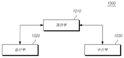
도 10은 또 다른 실시예에 의한 기지국(1000)의 구성을 보여주는 도면이다.10 is a diagram showing the configuration of a
도 10을 참조하면, 또 다른 실시예에 의한 기지국(1000)은 제어부(1010)과 송신부(1020), 수신부(1030)를 포함한다.Referring to FIG. 10, the
제어부(1010)는 전술한 본 발명을 수행하기에 필요한 차세대 무선망에서 사이드링크 통신에서 CQI를 관리하는 방법에 따른 전반적인 기지국(1000)의 동작을 제어한다.The
송신부(1020)와 수신부(1030)는 전술한 본 발명을 수행하기에 필요한 신호나 메시지, 데이터를 단말과 송수신하는데 사용된다. The
도 11은 또 다른 실시예에 의한 사용자 단말(1100)의 구성을 보여주는 도면이다.11 is a diagram showing the configuration of a
도 11을 참조하면, 또 다른 실시예에 의한 사용자 단말(1100)은 수신부(1110) 및 제어부(1120), 송신부(1130)를 포함한다.Referring to FIG. 11, the
수신부(1110)는 기지국으로부터 하향링크 제어 정보 및 데이터, 메시지를 해당 채널을 통해 수신한다.The
또한 제어부(1120)는 전술한 본 발명을 수행하기에 필요한 차세대 무선망에서 사이드링크 통신에서 CQI를 관리하는 방법에 따른 전반적인 사용자 단말(1100)의 동작을 제어한다.In addition, the
송신부(1130)는 기지국에 상향링크 제어 정보 및 데이터, 메시지를 해당 채널을 통해 전송한다.The
전술한 실시예들은 무선 접속 시스템들인 IEEE 802, 3GPP 및 3GPP2 중 적어도 하나에 개시된 표준 문서들에 의해 뒷받침될 수 있다. 즉, 본 실시 예들 중 본 기술적 사상을 명확히 드러내기 위해 설명하지 않은 단계, 구성, 부분들은 전술한 표준 문서들에 의해 뒷받침될 수 있다. 또한, 본 명세서에서 개시하고 있는 모든 용어들은위에서 개시한 표준 문서들에 의해 설명될 수 있다.The above-described embodiments can be supported by standard documents disclosed in at least one of the wireless access systems IEEE 802, 3GPP and 3GPP2. That is, steps, components, and parts that are not described in order to clearly reveal the technical idea among the embodiments may be supported by the above-described standard documents. In addition, all terms disclosed in this specification may be described by standard documents disclosed above.
상술한 본 실시예들은 다양한 수단을 통해 구현될 수 있다. 예를 들어, 본 실시예들은 하드웨어, 펌웨어(firmware), 소프트웨어 또는 그것들의 결합 등에 의해 구현될 수 있다.The above-described embodiments may be implemented through various means. For example, the embodiments can be implemented by hardware, firmware, software, or a combination thereof.
하드웨어에 의한 구현의 경우, 본 실시예들에 따른 방법은 하나 또는 그 이상의 ASICs(Application Specific Integrated Circuits), DSPs(Digital Signal Processors), DSPDs(Digital Signal Processing Devices), PLDs(Programmable Logic Devices), FPGAs(Field Programmable Gate Arrays), 프로세서, 컨트롤러, 마이크로 컨트롤러, 마이크로 프로세서 등에 의해 구현될 수 있다.For implementation by hardware, the method according to the embodiments includes one or more Application Specific Integrated Circuits (ASICs), Digital Signal Processors (DSPs), Digital Signal Processing Devices (DSPDs), Programmable Logic Devices (PLDs), FPGAs (Field Programmable Gate Arrays), processors, controllers, microcontrollers, microprocessors, and the like.
펌웨어나 소프트웨어에 의한 구현의 경우, 본 실시예들에 따른 방법은 이상에서 설명된 기능 또는 동작들을 수행하는 장치, 절차 또는 함수 등의 형태로 구현될 수 있다. 소프트웨어 코드는 메모리 유닛에 저장되어 프로세서에 의해 구동될 수 있다. 상기 메모리 유닛은 상기 프로세서 내부 또는 외부에 위치하여, 이미 공지된 다양한 수단에 의해 상기 프로세서와 데이터를 주고 받을 수 있다.In the case of implementation by firmware or software, the method according to the embodiments may be implemented in the form of an apparatus, procedure, or function that performs the functions or operations described above. The software code can be stored in a memory unit and driven by a processor. The memory unit is located inside or outside the processor, and can exchange data with the processor by various known means.
또한, 위에서 설명한 "시스템", "프로세서", "컨트롤러", "컴포넌트", "모듈", "인터페이스", "모델", "유닛" 등의 용어는 일반적으로 컴퓨터 관련 엔티티 하드웨어, 하드웨어와 소프트웨어의 조합, 소프트웨어 또는 실행 중인 소프트웨어를 의미할 수 있다. 예를 들어, 전술한 구성요소는 프로세서에 의해서 구동되는 프로세스, 프로세서, 컨트롤러, 제어 프로세서, 개체, 실행 스레드, 프로그램 및/또는 컴퓨터일 수 있지만 이에 국한되지 않는다. 예를 들어, 컨트롤러 또는 프로세서에서 실행 중인 애플리케이션과 컨트롤러 또는 프로세서가 모두 구성 요소가 될 수 있습니다. 하나 이상의 구성 요소가 프로세스 및/또는 실행 스레드 내에 있을 수 있으며 구성 요소는 한 시스템에 위치하거나 두 대 이상의 시스템에 배포될 수 있습니다.In addition, the terms "system", "processor", "controller", "component", "module", "interface", "model" and "unit" described above generally refer to computer-related entity hardware, hardware and software. It can mean a combination, software or running software. For example, the above-described components may be, but are not limited to, a processor driven process, a processor, a controller, a control processor, an object, an execution thread, a program, and / or a computer. For example, both an application running on a controller or processor and a controller or processor can be a component. One or more components can be in a process and / or thread of execution, and the components can be located on one system or deployed to more than one system.
이상에서의 설명 및 첨부된 도면은 본 기술 사상을 예시적으로 나타낸 것에 불과한 것으로서, 본 기술 분야에서 통상의 지식을 가진 자라면 본 기술의 본질적인 특성에서 벗어나지 않는 범위에서 구성의 결합, 분리, 치환 및 변경 등의 다양한 수정 및 변형이 가능할 것이다. 따라서, 본 명세서에 개시된 실시 예들은 본 기술 사상을 한정하기 위한 것이 아니라 설명하기 위한 것이고, 이러한 실시 예에 의하여 본 기술 사상의 범위가 한정되는 것은 아니다. 본 기술 사상의 보호 범위는 청구범위에 의하여 해석되어야 하며, 그와 동등한 범위 내에 있는 모든 기술 사상은 본 명세서의 권리범위에 포함되는 것으로 해석되어야 할 것이다.The above description and the accompanying drawings are merely illustrative of the technical idea of the present invention, and those of ordinary skill in the art may combine, separate, and replace configurations without departing from the essential characteristics of the present technology. Various modifications and variations such as changes will be possible. Therefore, the embodiments disclosed in the present specification are not intended to limit the technical spirit, but to explain, and the scope of the technical spirit is not limited by these embodiments. The scope of protection of the technical spirit should be interpreted by the claims, and all technical spirits within the scope equivalent thereto should be interpreted as being included in the scope of the present specification.
Claims (1)
단말이 그룹캐스트로 설정된 타 단말들의 CSI를 기초로 하여, 상기 타 단말들 중에서 CSI 리포팅을 수행할 단말을 설정하는 것을 특징으로 하는 방법.
A method for managing CQI in sidelink communication in a next generation wireless network,
Method for setting a terminal to perform CSI reporting among the other terminals, based on the CSI of the other terminals set by the group cast.
Priority Applications (1)
| Application Number | Priority Date | Filing Date | Title |
|---|---|---|---|
| KR1020180133640A KR20200051096A (en) | 2018-11-02 | 2018-11-02 | Apparatus and method of CQI management for group-based side-link in new radio |
Applications Claiming Priority (1)
| Application Number | Priority Date | Filing Date | Title |
|---|---|---|---|
| KR1020180133640A KR20200051096A (en) | 2018-11-02 | 2018-11-02 | Apparatus and method of CQI management for group-based side-link in new radio |
Publications (1)
| Publication Number | Publication Date |
|---|---|
| KR20200051096A true KR20200051096A (en) | 2020-05-13 |
Family
ID=70730053
Family Applications (1)
| Application Number | Title | Priority Date | Filing Date |
|---|---|---|---|
| KR1020180133640A KR20200051096A (en) | 2018-11-02 | 2018-11-02 | Apparatus and method of CQI management for group-based side-link in new radio |
Country Status (1)
| Country | Link |
|---|---|
| KR (1) | KR20200051096A (en) |
Cited By (1)
| Publication number | Priority date | Publication date | Assignee | Title |
|---|---|---|---|---|
| WO2021236376A1 (en) * | 2020-05-21 | 2021-11-25 | Kyocera Corporation | Hybrid automatic repeat request (harq) feedback management based on location information availability and sidelink signal quality for group sidelink communication |
-
2018
- 2018-11-02 KR KR1020180133640A patent/KR20200051096A/en unknown
Cited By (1)
| Publication number | Priority date | Publication date | Assignee | Title |
|---|---|---|---|---|
| WO2021236376A1 (en) * | 2020-05-21 | 2021-11-25 | Kyocera Corporation | Hybrid automatic repeat request (harq) feedback management based on location information availability and sidelink signal quality for group sidelink communication |
Similar Documents
| Publication | Publication Date | Title |
|---|---|---|
| US11258532B2 (en) | Method and apparatus for data modulation and coding for new radio | |
| US11627560B2 (en) | Method and apparatus for transmitting and receiving uplink control information | |
| US11582089B2 (en) | Method and apparatus for transmitting uplink channel in unlicensed band | |
| US20220086032A1 (en) | Method and device for transmitting and receiving uplink control information | |
| KR102392079B1 (en) | Apparatus and Method of performing positioning in new radio | |
| KR102298009B1 (en) | Method for Transmitting Uplink data channel and Apparatus thereof | |
| US11445543B2 (en) | Method and apparatus for performing listen before talk (LBT) for wireless communication in unlicensed band | |
| KR20190132228A (en) | Method and apparatus for transmitting harq feedback information in unlicensed band | |
| KR102320416B1 (en) | Method for Transmitting Uplink data and Apparatus thereof | |
| EP3512138A1 (en) | Method and apparatus for data modulation and coding for new radio | |
| US11671984B2 (en) | Method and apparatus for controlling search space for power saving | |
| US20220167404A1 (en) | Method and device for transmitting or receiving data in unlicensed band | |
| EP3944573A1 (en) | Apparatus and method for transmitting and receiving uplink channel | |
| KR20200051096A (en) | Apparatus and method of CQI management for group-based side-link in new radio | |
| KR20220039894A (en) | Method and apparatus of determining modulation and coding scheme | |
| KR20200087084A (en) | Method and apparatus for transmitting and receiving uplink control information | |
| KR20210017777A (en) | Apparatus and method of frequency-domain PRS muting in new radio | |
| KR20200100258A (en) | Method for transmitting an uplink shared channel including uplink control information in a next generation wireless network and Apparatuses thereof | |
| KR20200049953A (en) | Apparatus and method of information feedback related on positioning measurement in new radio | |
| US20220393716A1 (en) | Method and apparatus of frequency hopping for uplink transmission and reception | |
| KR102173331B1 (en) | Methods for data modulation and coding for new radio and Appratuses thereof | |
| US20230370228A1 (en) | Method and device for reducing overhead of positioning reference signal transmission | |
| US20230337180A1 (en) | Method and apparatus for controlling paging operation | |
| KR20220165859A (en) | Method and apparatus of transmission repetition above frequency resource region | |
| KR20200100522A (en) | Methods for transmitting an Uplink data for improving data transmission delay time in a next generation wireless network for And Apparatuses thereof |