KR20200049806A - Elastic wallboard mounting channels to accommodate standard fasteners - Google Patents
Elastic wallboard mounting channels to accommodate standard fasteners Download PDFInfo
- Publication number
- KR20200049806A KR20200049806A KR1020207008585A KR20207008585A KR20200049806A KR 20200049806 A KR20200049806 A KR 20200049806A KR 1020207008585 A KR1020207008585 A KR 1020207008585A KR 20207008585 A KR20207008585 A KR 20207008585A KR 20200049806 A KR20200049806 A KR 20200049806A
- Authority
- KR
- South Korea
- Prior art keywords
- web
- elastic
- channel
- inclined web
- edge portion
- Prior art date
Links
- 238000009432 framing Methods 0.000 abstract description 6
- 238000010276 construction Methods 0.000 description 7
- 230000005540 biological transmission Effects 0.000 description 6
- 238000009413 insulation Methods 0.000 description 6
- 239000000463 material Substances 0.000 description 3
- 229910000831 Steel Inorganic materials 0.000 description 2
- 230000008901 benefit Effects 0.000 description 2
- 230000000295 complement effect Effects 0.000 description 2
- 229910052602 gypsum Inorganic materials 0.000 description 2
- 239000010440 gypsum Substances 0.000 description 2
- 238000000034 method Methods 0.000 description 2
- 239000010959 steel Substances 0.000 description 2
- 239000000853 adhesive Substances 0.000 description 1
- 230000001070 adhesive effect Effects 0.000 description 1
- 230000002411 adverse Effects 0.000 description 1
- 238000005452 bending Methods 0.000 description 1
- 239000002131 composite material Substances 0.000 description 1
- 230000003111 delayed effect Effects 0.000 description 1
- 238000005516 engineering process Methods 0.000 description 1
- 238000009434 installation Methods 0.000 description 1
- 230000002452 interceptive effect Effects 0.000 description 1
- 239000011499 joint compound Substances 0.000 description 1
- 238000004519 manufacturing process Methods 0.000 description 1
- 239000002184 metal Substances 0.000 description 1
- 239000007769 metal material Substances 0.000 description 1
- 238000012986 modification Methods 0.000 description 1
- 230000004048 modification Effects 0.000 description 1
- 230000000149 penetrating effect Effects 0.000 description 1
- 238000010079 rubber tapping Methods 0.000 description 1
- 238000000926 separation method Methods 0.000 description 1
- 239000000126 substance Substances 0.000 description 1
- 239000002023 wood Substances 0.000 description 1
Images

Classifications
-
- E—FIXED CONSTRUCTIONS
- E04—BUILDING
- E04F—FINISHING WORK ON BUILDINGS, e.g. STAIRS, FLOORS
- E04F13/00—Coverings or linings, e.g. for walls or ceilings
- E04F13/07—Coverings or linings, e.g. for walls or ceilings composed of covering or lining elements; Sub-structures therefor; Fastening means therefor
- E04F13/08—Coverings or linings, e.g. for walls or ceilings composed of covering or lining elements; Sub-structures therefor; Fastening means therefor composed of a plurality of similar covering or lining elements
- E04F13/0801—Separate fastening elements
- E04F13/0803—Separate fastening elements with load-supporting elongated furring elements between wall and covering elements
-
- E—FIXED CONSTRUCTIONS
- E04—BUILDING
- E04B—GENERAL BUILDING CONSTRUCTIONS; WALLS, e.g. PARTITIONS; ROOFS; FLOORS; CEILINGS; INSULATION OR OTHER PROTECTION OF BUILDINGS
- E04B1/00—Constructions in general; Structures which are not restricted either to walls, e.g. partitions, or floors or ceilings or roofs
- E04B1/62—Insulation or other protection; Elements or use of specified material therefor
- E04B1/74—Heat, sound or noise insulation, absorption, or reflection; Other building methods affording favourable thermal or acoustical conditions, e.g. accumulating of heat within walls
- E04B1/82—Heat, sound or noise insulation, absorption, or reflection; Other building methods affording favourable thermal or acoustical conditions, e.g. accumulating of heat within walls specifically with respect to sound only
- E04B1/84—Sound-absorbing elements
-
- E—FIXED CONSTRUCTIONS
- E04—BUILDING
- E04B—GENERAL BUILDING CONSTRUCTIONS; WALLS, e.g. PARTITIONS; ROOFS; FLOORS; CEILINGS; INSULATION OR OTHER PROTECTION OF BUILDINGS
- E04B1/00—Constructions in general; Structures which are not restricted either to walls, e.g. partitions, or floors or ceilings or roofs
- E04B1/99—Room acoustics, i.e. forms of, or arrangements in, rooms for influencing or directing sound
-
- E—FIXED CONSTRUCTIONS
- E04—BUILDING
- E04B—GENERAL BUILDING CONSTRUCTIONS; WALLS, e.g. PARTITIONS; ROOFS; FLOORS; CEILINGS; INSULATION OR OTHER PROTECTION OF BUILDINGS
- E04B2/00—Walls, e.g. partitions, for buildings; Wall construction with regard to insulation; Connections specially adapted to walls
- E04B2/74—Removable non-load-bearing partitions; Partitions with a free upper edge
- E04B2/7407—Removable non-load-bearing partitions; Partitions with a free upper edge assembled using frames with infill panels or coverings only; made-up of panels and a support structure incorporating posts
- E04B2/7409—Removable non-load-bearing partitions; Partitions with a free upper edge assembled using frames with infill panels or coverings only; made-up of panels and a support structure incorporating posts special measures for sound or thermal insulation, including fire protection
- E04B2/7412—Posts or frame members specially adapted for reduced sound or heat transmission
-
- E—FIXED CONSTRUCTIONS
- E04—BUILDING
- E04B—GENERAL BUILDING CONSTRUCTIONS; WALLS, e.g. PARTITIONS; ROOFS; FLOORS; CEILINGS; INSULATION OR OTHER PROTECTION OF BUILDINGS
- E04B1/00—Constructions in general; Structures which are not restricted either to walls, e.g. partitions, or floors or ceilings or roofs
- E04B1/62—Insulation or other protection; Elements or use of specified material therefor
- E04B1/74—Heat, sound or noise insulation, absorption, or reflection; Other building methods affording favourable thermal or acoustical conditions, e.g. accumulating of heat within walls
- E04B1/82—Heat, sound or noise insulation, absorption, or reflection; Other building methods affording favourable thermal or acoustical conditions, e.g. accumulating of heat within walls specifically with respect to sound only
- E04B2001/8263—Mounting of acoustical elements on supporting structure, e.g. framework or wall surface
- E04B2001/8281—Flat elements mounted parallel to a supporting surface with an acoustically active air gap between the elements and the mounting surface
-
- E—FIXED CONSTRUCTIONS
- E04—BUILDING
- E04C—STRUCTURAL ELEMENTS; BUILDING MATERIALS
- E04C3/00—Structural elongated elements designed for load-supporting
- E04C3/02—Joists; Girders, trusses, or trusslike structures, e.g. prefabricated; Lintels; Transoms; Braces
- E04C3/04—Joists; Girders, trusses, or trusslike structures, e.g. prefabricated; Lintels; Transoms; Braces of metal
- E04C2003/0404—Joists; Girders, trusses, or trusslike structures, e.g. prefabricated; Lintels; Transoms; Braces of metal beams, girders, or joists characterised by cross-sectional aspects
- E04C2003/0443—Joists; Girders, trusses, or trusslike structures, e.g. prefabricated; Lintels; Transoms; Braces of metal beams, girders, or joists characterised by cross-sectional aspects characterised by substantial shape of the cross-section
- E04C2003/0482—Z- or S-shaped
Landscapes
- Engineering & Computer Science (AREA)
- Architecture (AREA)
- Physics & Mathematics (AREA)
- Acoustics & Sound (AREA)
- Civil Engineering (AREA)
- Structural Engineering (AREA)
- Electromagnetism (AREA)
- Thermal Sciences (AREA)
- Finishing Walls (AREA)
- Building Environments (AREA)
- Load-Bearing And Curtain Walls (AREA)
Abstract
골조 부재의 표면에 부착되고 표준 체결구를 수용하도록 구성 및 배열되는 개선된 탄성 벽판 지지 채널이 제공된다. 본 발명의 채널은 긴 모서리부를 갖는 대체로 평탄한 제1 면; 상기 긴 모서리부를 따라 배치되며 상기 제1 면에 대해 경사진 각도로 돌출하는 경사 웹; 상기 제1 면에 대향하며, 대체로 평탄한 제2 면과 공유되는, 상기 경사 웹의 웹 모서리부; 상기 경사 웹보다 짧으며, 상기 경사 웹에 대향하는 상기 제2 면의 단부 플랜지 모서리부로부터 돌출하는 단부 플랜지를 포함하되, 상기 제1 면과 상기 웹 모서리부는 골조 부재의 표면으로부터 수직으로 측정할 때 적어도 ¾인치만큼 이격된다.An improved elastic wallboard support channel is provided that is attached to the surface of the frame member and is constructed and arranged to receive a standard fastener. The channel of the present invention comprises a generally flat first surface with long edges; An inclined web disposed along the long edge portion and protruding at an inclined angle with respect to the first surface; A web edge portion of the inclined web facing the first surface and shared with a generally flat second surface; Shorter than the inclined web, including an end flange protruding from the end flange edge of the second face opposite the inclined web, wherein the first face and the web edge are vertically measured from the surface of the framing member At least ¾ inch apart.
Description
본 발명은 벽 및 천장 건축 기술에 관한 것으로, 보다 상세하게는 그러한 건축물에서 방음 및 화재 진행 지연을 위한 탄성 런너 채널(runner channel)의 사용에 관한 것이다.The present invention relates to wall and ceiling building technology, and more particularly, to the use of an elastic runner channel for sound insulation and delaying fire progress in such structures.
종래의 거주 및 사무용 건축에는 통상적으로 목재 또는 금속재 샛기둥(stud)을 수직으로 위치시키고, 유사하게 형성되는 상부재(header)와 하부재(footer)에 이격되고 나란한 배향으로 연결시키는 골조 건립을 필요로 한다. 골조는 전술한 상부재와 하부재에 연결되는 것으로서, 사이 사이에 기초바닥재(subfloor) 패널이 위치되는, 바닥 또는 천장 장선(長線)(joist)을 또한 포함한다. 다음에는, 전면 및 후면에 종이 등이 발라진 석고 합성물로 구성되는 것이 일반적인 벽판 패널(wallboard panel)이 골조에 고정되어 벽을 형성하며, 많은 경우에서는 천정도 형성한다. 관련 업계에 잘 알려진 바와 같이 벽판 결합제(joint compound)와 결합 테이프(joint tape)가 인접한 벽판 패널들 사이의 결합부를 충전하고 평활하게 하기 위해 사용된다. 이러한 건축 기술은 단일 가구 주거용으로는 적합하지만, 아파트 건물과 같은 다가구 거주 건물, 기숙사, 소형 호텔, 막사 등의 경우에는 전술한 바와 같은 종래의 방 건축은 방들 간에 즉각적인 소리의 전달을 쉽게 한다.Conventional residential and office construction typically requires the construction of a timber or metal frame with vertically positioned studs and a similarly formed heading and footer spaced apart and aligned in parallel orientations. Shall be The frame is connected to the upper and lower members described above, and also includes a floor or ceiling joist with a subfloor panel positioned between them. Next, a wallboard panel, which is generally composed of gypsum composite coated with paper or the like on the front and back, is fixed to a frame to form a wall, and in many cases, to form a ceiling. As is well known in the art, a joint compound and a joint tape are used to fill and smooth the joint between adjacent panel panels. Although this construction technique is suitable for single-family residential use, in the case of multi-family residential buildings such as apartment buildings, dormitories, small hotels, barracks, etc., conventional room construction as described above facilitates instantaneous sound transmission between rooms.
측방으로 인접한 방들 간에, 그리고 또한 수직으로 적층된 방들 간에 원치 않는 소리 전달 문제를 해결하기 위해, 본원에 인용되어 포함되는 공동 양수된 미국 특허 제3,090,164호에 기술된 바와 같은 탄성 채널이 개발되었다. 시간이 지남에 따라 산업계에 RC-1 채널로 알려지게 된 이러한 탄성 채널은 대체로 평행하게 측방으로 위치된 한 쌍의 평탄한 면을 갖는다. RC-1 채널의 몇몇 길이부들이 이격되어 나란하고 수평인 배향으로 골조에, 바람직하게는 샛기둥 또는 장선에 설치된다. 제1 면은 기부라 불리며, 못, 나사 체결구 등으로 골조 부재에 체결된다. 각진 플랜지가 제1 면과 제2 면을 연결하며, 제2 면을 기부의 측방에 위치시킨다. 벽판 패널은 제2 면에 고정되며, 이 면은 기부의 대향 단부에서 골조 부재에 대해 이격된다. 이렇게 하여, 벽판 패널은 RC-1 채널에 의해 골조 부재로부터 떨어져서 현수된다.To solve the undesired sound transmission problem between laterally adjacent rooms and also between vertically stacked rooms, elastic channels have been developed as described in the co- pumped U.S. Patent No. 3,090,164 incorporated herein by reference. Over time, these elastic channels, which have become known to the industry as RC-1 channels, have a pair of flat sides that are generally located laterally in parallel. Several lengths of the RC-1 channel are spaced apart and placed in a frame in a parallel and horizontal orientation, preferably in a column or joist. The first side is called a base, and is fastened to the frame member with nails, screw fasteners, and the like. An angled flange connects the first face and the second face, and places the second face on the side of the base. The wallboard panel is fixed to the second side, which is spaced against the frame member at the opposite end of the base. In this way, the wallboard panel is suspended away from the frame member by the RC-1 channel.
패널에 충돌하는 소리 에너지는 통상적으로 패널을 통해 직접 골조로 전달되어 건물 전체로 퍼지는데, 벽판 패널을 골조와 이격시킴으로써, 이 소리 에너지는 벽판 패널과 충돌할 때 RC-1 채널에 의해 간섭된 전달 통로를 갖기 때문에 감소된다. RC-1 채널의 또 다른 장점은 화재가 벽판 패널에 악영향을 미쳐도 채널이 설치된 방의 화재 진행이 지연된다는 점인데, 이는 불꽃과 열이 골조를 통해 건물의 다른 부분으로 직접 전달되기 않기 때문이다.The sound energy impinging on the panel is usually transmitted directly to the frame through the panel and spread throughout the building. By separating the wall panel from the frame, this sound energy is transmitted by the RC-1 channel when colliding with the wall panel. It is reduced because it has a passage. Another advantage of the RC-1 channel is that even if the fire adversely affects the wall paneling, the fire progress in the room where the channel is installed is delayed, as flames and heat are not transmitted directly to other parts of the building through the frame.
RC-1 채널의 사용에 대한 UL(Underwriter's Laboratories) 표준뿐만 아니라 건축법규는 1인치 체결구, 통상적으로 종래의 벽판 나사 등의 사용을 요구한다. 그러나, 실제로 작업자는 그러한 체결구를 사용하여 벽판 패널을 관통시키고, 계획적으로 움직일 수 있는 RC-1 채널의 유연성 제2 면을 교차시키는 데 있어서 실망하게 되었다. 일부 경우에서는, 체결구 선단이 자체 태핑(self-tapping)한다는 점에도 불구하고 체결구 선단의 확실한 접촉점을 위치시키기가 어렵다. 1인치 체결구의 사용을 저해하는 또 다른 요소는 전통적인 건축 현장에서의 사용을 위한 통상적인 크기가 아니라는 것이다. 오히려, 보다 일반적인 크기는 1¼ 인치 체결구다. 작업자가 RC-1 채널에 벽판 패널을 설치할 때 보다 긴 체결구를 사용하면, 체결구가 RC-1 채널의 제2 면을 관통하여 연장되며 샛기둥 또는 장선과 같은 하부의 골조 부재와 만나서 벽 또는 천장을 관통하는 음향 전달 통로를 형성함으로써 RC-1 채널의 방음 이익을 현저하게 감소시킨다는 것이 또한 밝혀졌다. 마찬가지로, 보다 긴 체결구는 벽판 패널로부터 골조 부재까지의 전도 통로를 만들어서 화재 시 불길을 통해 열과 불꽃의 진행이 가속된다.In addition to UL (Underwriter's Laboratories) standards for the use of RC-1 channels, building codes require the use of 1-inch fasteners, typically conventional wall plate screws, and the like. However, in practice, the operator was disappointed in using such fasteners to penetrate the wallboard panel and cross the flexible second side of the RC-1 channel, which was deliberately movable. In some cases, despite the fact that the fastener tip is self-tapping, it is difficult to locate a reliable contact point of the fastener tip. Another factor that hinders the use of 1-inch fasteners is that they are not the typical size for use in traditional building sites. Rather, the more common size is a 1¼ inch fastener. If an operator uses a longer fastener when installing a wallboard panel on the RC-1 channel, the fastener extends through the second side of the RC-1 channel and meets the lower frame member such as a stud or joist to meet the wall or It has also been found that forming a sound transmission passage through the ceiling significantly reduces the sound insulation benefits of the RC-1 channel. Likewise, longer fasteners create a conduction passage from the wallboard panel to the framing member, which accelerates the progress of heat and flame through the flames in the event of a fire.
작업자가 너무 긴 체결구를 사용함에 따른 문제를 해결하기 위한 하나의 시도는 본원에 인용되어 포함되는 공동 양수된 미국 특허출원공개 제2009/0173029호에 기술된 바와 같은 타입의 차음(遮音) 클립을 사용하는 것이다. 위 문헌에서, 차음 클립은 RC-1 채널을 골조 부재로부터 이격시키는 두께를 가져서 긴 체결구는 골조 부재에 도달하지 않는다. 그러나, 이러한 차음 클립의 사용에 대해 어느 정도의 상업적 거부감이 있다.One attempt to solve the problem of the operator using too long fasteners is to create a soundproofing clip of the type as described in co-acquired U.S. Patent Application Publication No. 2009/0173029, incorporated herein by reference. Is to use In the above document, the sound insulation clip has a thickness that separates the RC-1 channel from the frame member so that the long fastener does not reach the frame member. However, there is some degree of commercial objection to the use of these sound insulation clips.
따라서, 소망하는 방음 특성을 유지하면서 보다 긴 체결구를 수용할 수 있는 개선된 RC-1 채널에 대한 요구가 있다.Accordingly, there is a need for an improved RC-1 channel that can accommodate longer fasteners while maintaining desired sound insulation properties.
본원에서 1¼ 인치 길이의 벽판 체결구, 바람직하게는 나사 또는 못을 지칭하는 것으로 이해될 표준 체결구를 수용하도록 구성 및 배열된 본 발명의 벽판 설치 탄성 채널은 위와 같은 요구를 충족 또는 뛰어 넘는다. 관련 업계에 알려진 바와 같이, RC-1 채널은 일반적으로 못을 사용하여 골조에 고정되나, 벽판 패널은 나사를 사용하여 RC-1 채널에 부착하는 것이 일반적이다. 응용 여하에 따라 다른 체결구가 고려된다. 본 발명의 RC-1 채널은, 선형으로 이격된 부착 구멍이 구비되는 것이 바람직한 대체로 평탄한 제1 면 또는 기부를 포함한다. 기부의 일 모서리부를 따라 경사 웹 또는 플랜지가 소정의 비스듬한 각도로 돌출한다. 기부에 대향하는 플렌지의 일 모서리부는 대체로 평탄한 제2 면 또는 지지요소와 공유되며, 여기에 벽판 패널이 설치된다. 경사 웹보다 짧은 단부 플랜지(stop flange)가 경사 웹에 대향하는 제2 면의 웹 모서리부로부터 돌출하되 제2 면에 대해 둔각으로 돌출한다. 본 발명의 채널의 특징은 기부와 웹 모서리부 사이의 거리가 적어도 ¾인치이어서 1/2 또는 5/8인치 벽판 패널과 RC-1 채널을 관통하는 1¼인치 체결구가 하부의 골조 부재와 접하지 않는다는 것이다.Wallboard mounting elastic channels of the present invention constructed and arranged to accommodate a standard fastener that will be understood herein to refer to a 1¼ inch long wallboard fastener, preferably a screw or nail, meet or exceed these needs. As is known in the art, the RC-1 channel is generally secured to the frame using nails, but the wallboard panel is generally attached to the RC-1 channel using screws. Other fasteners are considered depending on the application. The RC-1 channel of the present invention includes a generally flat first surface or base where it is desirable to have a linearly spaced attachment hole. An inclined web or flange protrudes at a predetermined oblique angle along one edge of the base. One edge of the flange facing the base is shared with a generally flat second face or support element, where a wallboard panel is installed. A stop flange shorter than the inclined web protrudes from the web edge of the second face opposite the inclined web, but at an obtuse angle to the second face. The feature of the channel of the present invention is that the distance between the base and the edge of the web is at least ¾ inch so that the 1/2 or 5/8 inch wall panel and the 1¼ inch fastener penetrating the RC-1 channel do not contact the lower frame member. Is that
또한, 본 RC-1 채널은 경사 웹을 지지 요소에 연결하며 지지요소를 단부 플랜지에 연결하는 지지 립을 포함하여서 채널에 구조적 강도를 제공하고, 또한 체결구와 골조 부재 사이의 거리를 약간 증가시킨다. 또한 경사 웹에는 적어도 하나, 바람직하게는 선형으로 이격되는 복수의 절취부가 제공되어서 골조 부재에 설치 시 탄성을 증가시킨다. 절취부의 형상과 배열은 상황에 따라 변경될 수 있다.In addition, the RC-1 channel includes a support lip that connects the inclined web to the support element and connects the support element to the end flange, providing structural strength to the channel, and also slightly increasing the distance between the fastener and the frame member. In addition, the slanted web is provided with at least one cutout, preferably linearly spaced apart, to increase elasticity when installed in a framing member. The shape and arrangement of the perforations can be changed depending on the situation.
보다 상세하게, 본 발명은 표준 체결구를 수용하며 골조 부재의 표면에 부착되도록 구성 및 배열된 탄성의 벽판 채널을 제공한다. 본 발명의 채널은 긴 모서리부(elongate edge)를 갖는 대체로 평탄한 제1 면; 상기 긴 모서리부를 따라 배치되며 상기 제1 면에 대해 경사진 각도로 돌출하는 경사 웹(inclined web); 상기 제1 면에 대향하며, 대체로 평탄한 제2 면과 공유되는, 상기 경사 웹의 웹 모서리부; 상기 경사 웹보다 짧으며, 상기 경사 웹에 대향하는 상기 제2 면의 단부 플랜지 모서리부(stop flange edge)로부터 돌출하는 단부 플랜지(stop flange)를 포함하되, 상기 제1 면과 상기 웹 모서리부는 골조 부재의 표면으로부터 수직으로 측정할 때 적어도 ¾인치만큼 이격된다.More specifically, the present invention provides an elastic wallboard channel constructed and arranged to accommodate a standard fastener and to be attached to the surface of a frame member. The channel of the present invention comprises a generally flat first surface having an elongate edge; An inclined web disposed along the long edge and protruding at an angle inclined to the first surface; A web edge portion of the inclined web facing the first surface and shared with a generally flat second surface; Shorter than the inclined web, including an end flange (stop flange) protruding from the end flange edge (stop flange edge) of the second surface facing the inclined web, the first surface and the web edge portion frame When measured vertically from the surface of the member, it is at least ¾ inch apart.
또 다른 실시예에서, 골조 부재의 표면에 부착되도록 구성 및 배열된 탄성 벽판 지지 채널이 제공된다. 이 채널은 긴 모서리부를 갖는 대체로 평탄한 제1 면과, 중첩하여 접힌 반대측 자유 모서리부를 갖는다. 경사 웹이 긴 모서리부를 따라 배열되며 제1 면에 대해 경사진 각도로 돌출하되, 이 경사 웹에는, 골조 부재에 설치 시 탄성 증가를 위한 선형으로 이격된 복수의 절취부가 제공된다. 제1 면에 대향하는 경사 웹의 웹 모서리부가 대체로 평탄한 제2 면과 공유된다. 경사 웹과 제2 면의 인접한 모서리부들 사이에 원호형 지지 립이 형성된다. 경사 웹보다 짧은 단부 플랜지가 경사 웹에 대향하는 제2 면의 단부 플랜지 모서리부로부터 돌출하며, 원호형 지지 립이 제2 면과 단부 플랜지의 인접한 모서리부들 사이에 형성된다. 또한, 단부 플랜지는 경사 웹과 유사한 각도로 제2 면으로부터 돌출한다. 제1 면과 웹 모서리부의 표면은 골조 부재의 표면으로부터 수직으로 측정할 때 적어도 ¾인치 이격된다.In another embodiment, an elastic wallboard support channel is provided and constructed and arranged to attach to the surface of a framing member. The channel has a generally flat first face with a long edge, and an opposite free edge folded in overlap. The inclined web is arranged along the long edge and protrudes at an angle inclined with respect to the first surface, but this inclined web is provided with a plurality of linearly spaced cutouts for increased elasticity when installed in a framing member. The web edge portion of the inclined web facing the first side is shared with the generally flat second side. An arcuate support lip is formed between the inclined web and adjacent corners of the second face. An end flange shorter than the inclined web projects from the end flange edge of the second face opposite the inclined web, and an arcuate support lip is formed between the second face and adjacent edges of the end flange. Further, the end flange projects from the second face at an angle similar to the inclined web. The surfaces of the first face and the web corners are at least ¾ inch apart when measured vertically from the surface of the frame member.
바람직한 실시예에서, 경사각은 둔각이다.In a preferred embodiment, the angle of inclination is an obtuse angle.
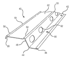
도 1은 공지의 RC-1 채널을 사용하여 건축중인 방 내부의 사시도이다.
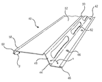
도 2는 본 발명에 따른 RC-1 채널의 전방 사시도이다.
도 3은 본 발명에 따른 RC-1 채널의 또 다른 실시예의 전방 사시도이다.
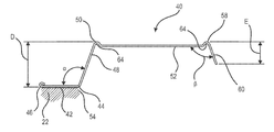
도 4는 본 발명에 따른 RC-1 채널의 단부도이다.
도 5는 본 발명의 RC-1 채널이 골조 부재에 설치되며 벽판 패널이 이 RC-1 채널에 부착된 것을 보여주는 부분사시도이다.1 is a perspective view of a room under construction using a known RC-1 channel.
2 is a front perspective view of the RC-1 channel according to the present invention.
3 is a front perspective view of another embodiment of the RC-1 channel according to the present invention.
4 is an end view of an RC-1 channel according to the present invention.
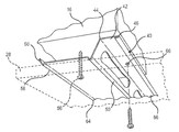
Figure 5 is a partial perspective view showing that the RC-1 channel of the present invention is installed on a framing member and the wallboard panel is attached to this RC-1 channel.
도 1을 참조하면, 전반에 걸쳐 도면 부호 10으로 표시된 방의 일부가 예시되며, 예시된 방은 한 쌍의 벽(12, 14)을 포함하되 각 벽은 적어도 하나의 하부재(footer) 또는 기부(18), 적어도 하나의 상부재(header) 또는 상부 지지부재(20), 및 하부재(들)와 상부재(들)를 연결하는 복수의 수직부재 또는 샛기둥(22)을 포함하는 골조(16)에 의해 지지된다. 관련 업계에 잘 알려진 바와 같이, 샛기둥(22)은 중심에서 중심까지 16인치와 같은 일정한 간격, 또는 지역의 건축법규에 따른 간격으로 위치된다. 또한 골조(16)는 바람직하게는 2X4널판지 또는 다른 사이즈의 목재로 만들어지는 것이 통상적이나, 강과 같은 금속재, 또는 다른 재료를 사용하는 건축기술이 고려된다. 천장 장선(24)은 상부재(들)(20)에 고정되며, 원하는 건물의 높이에 따라 지붕 또는 위층을 지지하기 위해 사용된다. 관련업계에 알려진 바와 같이, 골조(16)는 못 또는 나사와 같은 체결구를 사용하여 조립된다. 장선(24)뿐만 아니라 하부재(18), 상부재(20), 샛기둥(22)은 총칭하여 골조 부재로 칭한다.Referring to FIG. 1, a part of the room indicated by
방들 간의 소리 전달을 억제하려고 하는 응용에서, 적당한 체결구(도시되지 않음)를 사용하여 RC-1 채널 또는 런너(26)를 직접 샛기둥(22)에 또는 다른 골조 부재에, 채널(26)이 골조 부재에 대해 횡방향으로 연장되도록, 이격하여 평행한 배향으로 설치하는 것이 보통이다. 다음에는 석고보드 등으로 된 벽판 패널(28)을 나사, 못 또는 화학접착제와 같은 체결구를 사용하여 RC-1 채널에 고정한다. 이렇게 하여, 벽판 패널(28)이 RC-1 채널(26)에 의해 골조(16)로부터 떨어진 거리를 유지하여서 패널로부터 골조로의 음향 전달의 통로를 간섭함으로써 방들 간의 소음 전달을 감소시킨다.In applications that attempt to suppress sound transmission between rooms, the
본 개시에서 다루어지는 문제점은 많은 지역의 건축법규뿐만 아니라 UL 표준에서는 패널(28)을 골조(16)에 설치하는 데 1인치 길이의 체결구를 사용하는 것을 규정하고 있다는 것이다. 그러나 1인치 체결구는 건축현장에서의 통상적인 목록의 물품이 아니며, 많은 작업자들은 이러한 체결구가 골조(16)에 대한 패널(28)의 확실한 부착에 적합하지 않다고 생각하기 때문에, 통상적으로 작업자들은 벽판 패널(28)을 RC-1 채널에 부착할 때 1¼ 인치 나사를 사용한다. 불행히도 이 1¼ 인치 체결구는 벽판 패널(28), RC-1 채널(26)을 관통하여 심지어 골조(16)에 도달할 정도로 길며, 따라서 음향학상으로 벽판 패널을 골조에 연결하여서 채널(26)의 방음특성을 현저하게 감소시키거나 없게 한다.The problem addressed in this disclosure is that many local building codes as well as UL standards stipulate the use of a 1 inch long fastener to install the
도 2 내지 도 5를 참조하면, 이 문제를 해결하기 위해, 전반적으로 도면 부호 40으로 표시되는 개선된 RC-1 채널이 제공된다. 본 발명의 채널(40)의 주요 특징은 벽판 패널(28)과 골조(16) 사이에 충분한 간격을 형성하도록 구성 및 배열되어서 작업자가 이 채널을 설치하기 위해 1¼ 인치 체결구를 사용하는 경우에도 체결구가 골조에 도달하지 않아서 방(10)으로부터 전달되는 소리의 현저한 감소를 위한 간격을 유지한다는 것이다.2 to 5, in order to solve this problem, an improved RC-1 channel, generally indicated by 40, is provided. The main feature of the
RC-1 채널(40)은 긴 모서리부(44)와 반대측 자유 모서리부(46)를 갖는 대체로 평탄한 제1 면(42)을 포함한다. 경사 웹 또는 벽(48)이 긴 모서리부(44)를 따라 배열되며 제 1평면(42)에 대해 비스듬한 각도로 돌출한다. 각도(α)는 둔각이 바람직하며, 더욱 바람직하게는 각도(α)가 약 110° 내지 115°이다. 제1 평면(42)에 대향된 경사 웹(48)의 웹 모서리부(50)는 대체로 평탄한 제2 평면(52)의 상보형(complementary) 모서리부와 공유된다. 경사 웹(48)의 중요한 특징은 벽판 패널(28)(도 5)과 접하는 웹 모서리부(50)를 골조(16)의 표면(54)으로부터, 바람직하게는 샛기둥(22) 또는 다른 골조 부재로부터 수직으로 측정했을 때 적어도 ¾인치인 거리 "D"로 골조(16)와 이격되도록 하는 치수를 가져서 벽판 패널(28)을 RC-1 채널에 고정하기 위해 상대적으로 긴 1¼ 인치 체결구(56)가 사용되어도 이 체결구가, 도 5에 도시된 바와 같이, 골조에 접하지 않게 된다는 것이다. 즉, 체결구(56)의 선단이 샛기둥(22), 또는 골조(16)의 다른 골조 부재와 같은 각 부재에 도달하지 않을 것이다. 이러한 방식으로, RC-1 채널을 설치 시 중요한 요소로서 전술한 바와 같은 음향학적인 이격이 보다 긴 체결구를 사용하여 체결할 때도 유지된다.The RC-1
단부 플랜지 모서리부(58)가 제2 평면(52)에 위치되되 웹 모서리부(50)와 대체로 수평으로 정렬된다. 또한, 단부 플랜지 모서리부(58)는 단부 플랜지(60)와 제2 평면(52)의 인접하거나 또는 상보형인 모서리부들의 교차부에 위치되고, 단부 플랜지가 돌출하게 되는 기부를 형성하며, 단부 플랜지는 경사 웹(48)보다 짧으며, 경사 웹(50)에 대향하는 제2 평면(52)으로부터 돌출한다.The
도 2 내지 도 4를 참조하면, 채널(40)은 구조 전체가 강 스트립으로부터 전조 가공(roll forming) 및 스탬핑 가공(stamping)에 의해 제조되며, 관련 업계에 잘 알려진 바와 같이, 아연도금 또는 다른 방청처리 후 예시된 바와 같은 형태로 형성되는 것이 바람직하다. 제조 공정 중에, 경사 웹(48)에는, 수직 골조 부재(22)에 부착 시 탄성 증가를 위한 선형으로 이격된 복수의 절취부(62)가 제공되는 것이 바람직하다. 도 2 및 도 3에 도시된 바와 같이, 절취부(62)의 형태는 필요에 따라 변형될 수 있으나, 원, 타원, 장형(elongate) 슬롯 등이 고려된다. 또한, 바람직하기로는 단부 플랜지 모서리부(56)뿐만 아니라 웹 모서리부(50)에도 원호형 지지 립(64)을 형성함으로써 채널(40)에 향상된 구조적 강도를 제공한다. 그런데, 응용 여하에 따라서는 수 개의 립이 고려된다.Referring to Figures 2-4, the
도 4에 도시된 바와 같이, 단부 플랜지(58)는 제2 면과 경사 웹(48) 사이의 각도와 유사한 각도(β)로 제2 평면(52)으로부터 돌출한다. 각도(β)는 약 90° 내지 110°가 바람직하지만, 다른 각도도 고려된다. 채널(40)의 강도를 더욱 향상시키기 위해, 자유 모서리부(46)는 중첩되게 접힌다. 또한, 도 2, 도 3 및 도 5에서 잘 보이는 바와 같이, 제1 평면(42)에는 RC-1채널(40)을 골조(16)에 고정하기 위해 사용되며 선형으로 이격된 고정 구멍(66)이 제공되는 것이 바람직하다. 또한, 도 4에 거리 "E"로 표시된 바와 같이, 단부 플랜지(60)는 골조 부재에 대한 채널(40)의 굽힘을 방지하여서 체결구가 보다 용이하게 채널을 관통할 수 있도록 단부 플랜지 모서리부(58)로부터 적어도 1/2인치 연장되는 것이 바람직하다. 그러나 상황에 따라서는 다른 치수가 고려된다.As shown in FIG. 4, the
표준 체결구를 수용하는 본 발명의 탄성 벽판 채널의 특정 실시예가 개시되어 있으나, 통상의 기술자라면 다음의 청구범위에 기재된 바와 같은 광의의 양태의 본 발명으로부터 벗어나지 않고 변경 및 변형이 이루어질 수 있음을 이해하게 될 것이다.Although specific embodiments of the elastic wallboard channels of the present invention that accept standard fasteners have been disclosed, it is understood by those skilled in the art that modifications and variations can be made without departing from the invention in the broader aspects as set forth in the claims below. Will do.
Claims (8)
긴 모서리부(elongate edge)를 갖는 대체로 평탄한 제1 면;
상기 긴 모서리부를 따라 배치되며 상기 제1 면에 대해 경사진 각도로 돌출하는 경사 웹(inclined web);
상기 제1 면에 대향하며, 대체로 평탄한 제2 면과 공유되는, 상기 경사 웹의 웹 모서리부; 및
상기 경사 웹보다 짧으며, 상기 경사 웹에 대향하는 상기 제2 면의 단부 플랜지 모서리부(stop flange edge)로부터 돌출하는 단부 플랜지(stop flange)를 포함하되,
상기 제1 면과 상기 웹 모서리부는 골조 부재의 표면으로부터 수직으로 측정할 때 적어도 ¾인치만큼 이격되는, 탄성 벽판 지지 채널.An elastic wallboard support channel constructed and arranged to be attached to the surface of a frame member,
A generally flat first surface having an elongate edge;
An inclined web disposed along the long edge and protruding at an angle inclined to the first surface;
A web edge portion of the inclined web facing the first surface and shared with a generally flat second surface; And
A shorter end than the inclined web, and including an end flange protruding from a stop flange edge of the second face opposite the inclined web,
The first surface and the web edge portion is spaced at least ¾ inches when measured vertically from the surface of the frame member, the elastic wall plate support channel.
긴 모서리부와, 중첩하여 접힌 반대측 자유 모서리부를 갖는 대체로 평탄한 제1 면;
상기 긴 모서리부를 따라 배열되며, 상기 제1 면에 대해 경사진 각도로 돌출하되, 상기 골조 부재에 설치 시 탄성 증가를 위한 선형으로 이격된 복수의 절취부를 구비한 경사 웹;
상기 제1 면에 대향하며, 대체로 평탄한 제2 면과 공유되는, 상기 경사 웹의 웹 모서리부;
상기 경사 웹과 상기 제2 면의 인접한 모서리부들 사이에 형성된 원호형 지지 립;
상기 경사 웹보다 짧으며, 상기 경사 웹에 대향하는 상기 제2 면의 단부 플랜지 웹으로부터 돌출하되 상기 경사 웹과 유사한 각도로 상기 제2 면으로부터 돌출하는 단부 플랜지; 및
상기 제2 면과 상기 단부 플랜지의 인접한 모서리부들 사이에 형성된 원호형 지지 립을 포함하되,
상기 제1 면과 상기 웹 모서리부는 상기 골조 부재의 표면으로부터 수직으로 측정할 때 적어도 ¾인치 이격되는, 탄성 벽판 지지 채널.An elastic wallboard support channel constructed and arranged to be attached to the surface of a frame member,
A generally flat first surface having a long edge portion and an opposite free edge portion folded in overlap;
An inclined web which is arranged along the long edge portion and protrudes at an angle inclined with respect to the first surface, but has a plurality of linearly spaced cutouts for increased elasticity when installed on the frame member;
A web edge portion of the inclined web facing the first surface and shared with a generally flat second surface;
An arcuate support lip formed between the inclined web and adjacent corner portions of the second surface;
An end flange that is shorter than the inclined web and protrudes from the end flange web of the second face opposite the inclined web, but protrudes from the second face at an angle similar to the inclined web; And
It includes an arcuate support lip formed between the second surface and the adjacent edge portion of the end flange,
The first surface and the web edge portion is at least ¾ inches apart when measured vertically from the surface of the frame member, the elastic wall plate support channel.
Applications Claiming Priority (3)
| Application Number | Priority Date | Filing Date | Title |
|---|---|---|---|
| US15/704,958 US10260241B2 (en) | 2017-09-14 | 2017-09-14 | Resilient wallboard mounting channel accommodating standard fasteners |
| US15/704,958 | 2017-09-14 | ||
| PCT/US2018/050645 WO2019055501A1 (en) | 2017-09-14 | 2018-09-12 | Resilient wallboard mounting channel accommodating standard fasteners |
Publications (1)
| Publication Number | Publication Date |
|---|---|
| KR20200049806A true KR20200049806A (en) | 2020-05-08 |
Family
ID=63708485
Family Applications (1)
| Application Number | Title | Priority Date | Filing Date |
|---|---|---|---|
| KR1020207008585A KR20200049806A (en) | 2017-09-14 | 2018-09-12 | Elastic wallboard mounting channels to accommodate standard fasteners |
Country Status (8)
| Country | Link |
|---|---|
| US (1) | US10260241B2 (en) |
| EP (1) | EP3682071A1 (en) |
| JP (1) | JP2020535332A (en) |
| KR (1) | KR20200049806A (en) |
| AU (1) | AU2018334147A1 (en) |
| CA (1) | CA3074860A1 (en) |
| MX (1) | MX2020002839A (en) |
| WO (1) | WO2019055501A1 (en) |
Families Citing this family (6)
| Publication number | Priority date | Publication date | Assignee | Title |
|---|---|---|---|---|
| TWI743486B (en) * | 2019-06-03 | 2021-10-21 | 瑞克大衛國際有限公司 | Carrier assembly and male member, female member thereof |
| US11846105B2 (en) * | 2019-10-14 | 2023-12-19 | Russell Matson | Siding panel installation |
| USD943390S1 (en) * | 2020-06-26 | 2022-02-15 | Corsair Memory, Inc. | Mounting element for an acoustic panel |
| USD943391S1 (en) * | 2020-06-26 | 2022-02-15 | Corsair Memory, Inc. | Mounting element and bracket combination for an acoustic panel |
| US11578483B2 (en) * | 2021-04-29 | 2023-02-14 | Back-Lattice Wall Systems, Llc | Wall assembly |
| USD985802S1 (en) * | 2021-05-24 | 2023-05-09 | Super Stud Building Products, Inc. | Isolated resilient channel |
Family Cites Families (22)
| Publication number | Priority date | Publication date | Assignee | Title |
|---|---|---|---|---|
| US2752013A (en) | 1952-03-20 | 1956-06-26 | Dana Corp | Vehicle floor skid rail and securing means |
| US3090164A (en) * | 1961-09-25 | 1963-05-21 | United States Gypsum Co | Wall construction and resilient runner therefor |
| US3229435A (en) | 1963-01-23 | 1966-01-18 | Anders C Olsen | Built up wall structure |
| US3177620A (en) * | 1963-04-11 | 1965-04-13 | Donald A Brown | Resilient structureal beam |
| US3333379A (en) * | 1964-02-21 | 1967-08-01 | Nat Gypsum Co | Resilient furring channel |
| US3370391A (en) * | 1965-09-07 | 1968-02-27 | Kaiser Gypsum Company Inc | Resilient structural beam |
| US3421281A (en) * | 1965-10-04 | 1969-01-14 | Fibreboard Corp | Resilient channel member |
| US3391508A (en) * | 1965-12-02 | 1968-07-09 | Flintkote Co | Resilient furring strip for gypsum board wall system |
| US3401494A (en) * | 1967-01-23 | 1968-09-17 | Dallas A. Anderson | Metal stud for polystyrene foam sheets |
| US3477187A (en) * | 1968-01-19 | 1969-11-11 | Albert A Fruman | Wallboard mounting channel |
| USRE29965E (en) | 1973-07-25 | 1979-04-17 | Wall construction | |
| US3958386A (en) | 1974-04-08 | 1976-05-25 | Pollock Eugene B | Building structural system |
| US4227360A (en) * | 1977-05-05 | 1980-10-14 | United States Gypsum Company | Resilient furring member |
| US4170858A (en) * | 1977-06-02 | 1979-10-16 | United States Gypsum Company | Resilient runner for wall construction |
| US4660339A (en) * | 1985-11-20 | 1987-04-28 | Felix Paz | Wall system |
| US4750307A (en) * | 1986-07-01 | 1988-06-14 | United States Gypsum Company | Wall construction and resilient runner therefor |
| US5119612A (en) | 1990-05-11 | 1992-06-09 | Energy Blanket Of Texas, Inc. | Insulated roof structure with fire resistant panels mounted thereon |
| US20080008345A1 (en) | 2006-07-06 | 2008-01-10 | Supress Products, Llc | Method and apparatus for sound engineered metal channel supports and panel products |
| US20090173029A1 (en) * | 2008-01-07 | 2009-07-09 | Dennis Albert Socha | Polymeric acoustic isolator clip for isolating wallboard channels from frame member |
| US8857120B2 (en) | 2012-04-19 | 2014-10-14 | Panduit Corp. | Ceiling supported cold aisle containment system |
| US20130318904A1 (en) | 2012-06-04 | 2013-12-05 | United States Gypsum Company | Conventional fire-rated one-sided construction |
| US9051730B2 (en) | 2013-04-12 | 2015-06-09 | G2 Group LLC | System for sound isolation |
-
2017
- 2017-09-14 US US15/704,958 patent/US10260241B2/en active Active
-
2018
- 2018-09-12 WO PCT/US2018/050645 patent/WO2019055501A1/en unknown
- 2018-09-12 MX MX2020002839A patent/MX2020002839A/en unknown
- 2018-09-12 CA CA3074860A patent/CA3074860A1/en not_active Abandoned
- 2018-09-12 KR KR1020207008585A patent/KR20200049806A/en unknown
- 2018-09-12 EP EP18779531.5A patent/EP3682071A1/en not_active Withdrawn
- 2018-09-12 JP JP2020514971A patent/JP2020535332A/en active Pending
- 2018-09-12 AU AU2018334147A patent/AU2018334147A1/en not_active Abandoned
Also Published As
| Publication number | Publication date |
|---|---|
| EP3682071A1 (en) | 2020-07-22 |
| WO2019055501A1 (en) | 2019-03-21 |
| MX2020002839A (en) | 2020-07-22 |
| AU2018334147A1 (en) | 2020-04-16 |
| JP2020535332A (en) | 2020-12-03 |
| CA3074860A1 (en) | 2019-03-21 |
| US20190078335A1 (en) | 2019-03-14 |
| US10260241B2 (en) | 2019-04-16 |
Similar Documents
| Publication | Publication Date | Title |
|---|---|---|
| KR20200049806A (en) | Elastic wallboard mounting channels to accommodate standard fasteners | |
| US10358828B2 (en) | Methods of fastening a wall panel to a wall, kits, and wall assemblies | |
| US11649626B2 (en) | Hanger for fire separation wall | |
| US3090164A (en) | Wall construction and resilient runner therefor | |
| AU2019201196A1 (en) | Drywall joist hanger connection | |
| US10179992B2 (en) | Heavy duty hanger for fire separation wall | |
| US10309100B2 (en) | Mullion cover hanger and curtain wall insulation system incorporating the same | |
| US20210396000A1 (en) | Drywall Hanger | |
| US20220243455A1 (en) | Drywall Spacing Joist Hanger | |
| WO2018178726A2 (en) | Modular partition system | |
| US20090301026A1 (en) | Method and apparatus for connecting perpendicularly oriented structural building members | |
| US20180044910A1 (en) | Infill wall support clip | |
| AU2012231352B2 (en) | 30-minute residential fire protection of floors | |
| US1858715A (en) | Building construction | |
| JP6633320B2 (en) | Supports and ceiling structures | |
| JP2003171988A (en) | External wall as fireproofed bearing wall and floor | |
| WO2023054015A1 (en) | Panel installation structure | |
| US11408169B2 (en) | Z-shaped bracket for wood backing and fireproofing | |
| JP2023050772A (en) | Panel installation structure | |
| JPH05302381A (en) | Fire-proof structure of unit building | |
| JPH05302379A (en) | Fire-proof structure of unit building | |
| JP2003278358A (en) | Exterior wall panel for outside angle | |
| JPH08158527A (en) | Attachment structure for eave soffit | |
| JP2003013517A (en) | Fitting structure of external angle panel for wing wall in steel skeleton dwelling house | |
| JP2002339482A (en) | Outside angle panel mounting structure in steel framed house |