KR20200048984A - Hybrid plasma generator - Google Patents
Hybrid plasma generator Download PDFInfo
- Publication number
- KR20200048984A KR20200048984A KR1020180131705A KR20180131705A KR20200048984A KR 20200048984 A KR20200048984 A KR 20200048984A KR 1020180131705 A KR1020180131705 A KR 1020180131705A KR 20180131705 A KR20180131705 A KR 20180131705A KR 20200048984 A KR20200048984 A KR 20200048984A
- Authority
- KR
- South Korea
- Prior art keywords
- panel
- hybrid plasma
- reaction body
- plasma
- hybrid
- Prior art date
Links
- CBENFWSGALASAD-UHFFFAOYSA-N Ozone Chemical compound [O-][O+]=O CBENFWSGALASAD-UHFFFAOYSA-N 0.000 claims abstract description 21
- 238000009616 inductively coupled plasma Methods 0.000 claims abstract description 21
- 238000000034 method Methods 0.000 claims abstract description 17
- 238000004804 winding Methods 0.000 claims abstract description 8
- 239000007789 gas Substances 0.000 claims description 23
- QVGXLLKOCUKJST-UHFFFAOYSA-N atomic oxygen Chemical compound [O] QVGXLLKOCUKJST-UHFFFAOYSA-N 0.000 claims description 5
- 239000001301 oxygen Substances 0.000 claims description 5
- 229910052760 oxygen Inorganic materials 0.000 claims description 5
- 230000008569 process Effects 0.000 abstract description 13
- 238000004140 cleaning Methods 0.000 abstract description 9
- 210000002381 plasma Anatomy 0.000 description 104
- 238000004519 manufacturing process Methods 0.000 description 6
- 239000004065 semiconductor Substances 0.000 description 4
- 239000000758 substrate Substances 0.000 description 4
- 238000004380 ashing Methods 0.000 description 3
- MYMOFIZGZYHOMD-UHFFFAOYSA-N Dioxygen Chemical compound O=O MYMOFIZGZYHOMD-UHFFFAOYSA-N 0.000 description 2
- 229910001882 dioxygen Inorganic materials 0.000 description 2
- 230000000694 effects Effects 0.000 description 2
- 230000005672 electromagnetic field Effects 0.000 description 2
- 239000011521 glass Substances 0.000 description 2
- 239000011810 insulating material Substances 0.000 description 2
- 238000009413 insulation Methods 0.000 description 2
- 150000002500 ions Chemical class 0.000 description 2
- 230000035515 penetration Effects 0.000 description 2
- 229920002120 photoresistant polymer Polymers 0.000 description 2
- 235000012431 wafers Nutrition 0.000 description 2
- 230000004888 barrier function Effects 0.000 description 1
- 230000008859 change Effects 0.000 description 1
- 238000005229 chemical vapour deposition Methods 0.000 description 1
- 238000001816 cooling Methods 0.000 description 1
- 238000000151 deposition Methods 0.000 description 1
- 230000008021 deposition Effects 0.000 description 1
- 238000005516 engineering process Methods 0.000 description 1
- 238000005530 etching Methods 0.000 description 1
- 230000005284 excitation Effects 0.000 description 1
- 238000010849 ion bombardment Methods 0.000 description 1
- 238000003475 lamination Methods 0.000 description 1
- 238000012423 maintenance Methods 0.000 description 1
- 239000002184 metal Substances 0.000 description 1
- 238000012986 modification Methods 0.000 description 1
- 230000004048 modification Effects 0.000 description 1
- 210000000056 organ Anatomy 0.000 description 1
- 239000012495 reaction gas Substances 0.000 description 1
- 238000007789 sealing Methods 0.000 description 1
Images


Classifications
-
- H—ELECTRICITY
- H01—ELECTRIC ELEMENTS
- H01J—ELECTRIC DISCHARGE TUBES OR DISCHARGE LAMPS
- H01J37/00—Discharge tubes with provision for introducing objects or material to be exposed to the discharge, e.g. for the purpose of examination or processing thereof
- H01J37/32—Gas-filled discharge tubes
- H01J37/32009—Arrangements for generation of plasma specially adapted for examination or treatment of objects, e.g. plasma sources
- H01J37/32082—Radio frequency generated discharge
- H01J37/32091—Radio frequency generated discharge the radio frequency energy being capacitively coupled to the plasma
-
- H—ELECTRICITY
- H01—ELECTRIC ELEMENTS
- H01J—ELECTRIC DISCHARGE TUBES OR DISCHARGE LAMPS
- H01J37/00—Discharge tubes with provision for introducing objects or material to be exposed to the discharge, e.g. for the purpose of examination or processing thereof
- H01J37/32—Gas-filled discharge tubes
- H01J37/32009—Arrangements for generation of plasma specially adapted for examination or treatment of objects, e.g. plasma sources
- H01J37/32082—Radio frequency generated discharge
- H01J37/321—Radio frequency generated discharge the radio frequency energy being inductively coupled to the plasma
-
- H—ELECTRICITY
- H01—ELECTRIC ELEMENTS
- H01J—ELECTRIC DISCHARGE TUBES OR DISCHARGE LAMPS
- H01J37/00—Discharge tubes with provision for introducing objects or material to be exposed to the discharge, e.g. for the purpose of examination or processing thereof
- H01J37/32—Gas-filled discharge tubes
- H01J37/32431—Constructional details of the reactor
- H01J37/3244—Gas supply means
-
- H—ELECTRICITY
- H01—ELECTRIC ELEMENTS
- H01J—ELECTRIC DISCHARGE TUBES OR DISCHARGE LAMPS
- H01J37/00—Discharge tubes with provision for introducing objects or material to be exposed to the discharge, e.g. for the purpose of examination or processing thereof
- H01J37/32—Gas-filled discharge tubes
- H01J37/32431—Constructional details of the reactor
- H01J37/32798—Further details of plasma apparatus not provided for in groups H01J37/3244 - H01J37/32788; special provisions for cleaning or maintenance of the apparatus
- H01J37/32816—Pressure
- H01J37/32834—Exhausting
Landscapes
- Physics & Mathematics (AREA)
- Engineering & Computer Science (AREA)
- Plasma & Fusion (AREA)
- Chemical & Material Sciences (AREA)
- Analytical Chemistry (AREA)
- Plasma Technology (AREA)
Abstract
Description
본 발명은 하이브리드 플라즈마 발생 장치에 관한 것으로서, 보다 상세하게는 오존 가스나 세정 가스나 공정 가스 등 대용량 라디칼을 발생시킬 수 있는 하이브리드 플라즈마 발생 장치에 관한 것이다.The present invention relates to a hybrid plasma generating device, and more particularly, to a hybrid plasma generating device capable of generating large-capacity radicals such as ozone gas, cleaning gas, and process gas.
플라즈마 방전은 이온, 자유 라디칼, 원자, 분자를 포함하는 활성 가스를 발생하기 위한 가스 여기에 사용되고 있다. 활성 가스는 다양한 분야에서 널리 사용되고 있으며 대표적으로 반도체 제조 공정 예들 들어, 식각, 증착, 세정, 에싱 등 다양하게 사용되고 있다.Plasma discharge is used for gas excitation to generate an active gas containing ions, free radicals, atoms, and molecules. The active gas is widely used in various fields, and is typically used in various ways, such as etching, deposition, cleaning, and ashing of semiconductor manufacturing processes.
최근, 반도체 장치의 제조를 위한 웨이퍼나 LCD 글라스 기판은 더욱 대형화 되어 가고 있다. 그럼으로 플라즈마 이온 에너지에 대한 제어 능력이 높고, 대면적의 처리 능력을 갖는 확장성이 용이한 플라즈마 소스가 요구되고 있다.In recent years, wafers or LCD glass substrates for the manufacture of semiconductor devices are becoming larger. Accordingly, there is a need for a plasma source having a high control ability for plasma ion energy and easy scalability with a large area processing ability.
플라즈마를 이용한 반도체 제조 공정에서 원격 플라즈마의 사용은 매우 유용한 것으로 알려져 있다. 예를 들어, 공정 챔버의 세정이나 포토레지스트 스트립을 위한 에싱 공정에서 유용하게 사용되고 있다. 그런데, 피처리 기판의 대형화에 따라 공정 챔버의 볼륨도 증가되고 있어서 고밀도의 활성 가스를 충분히 원격으로 공급할 수 있는 플라즈마 소스가 요구되고 있다.The use of remote plasma in semiconductor manufacturing processes using plasma is known to be very useful. For example, it is useful in cleaning process chambers or ashing processes for photoresist strips. However, the volume of the process chamber is also increased with the increase in the size of the substrate to be processed, and a plasma source capable of sufficiently supplying a high-density active gas remotely is required.
한편, 원격 플라즈마 반응기(또는 원격 플라즈마 발생기라 칭함)는 변압기 결합 플라즈마 소스(transformer coupled plasma source)를 사용한 것과 유도 결합 플라즈마 소스(inductively coupled plasma source)과 용량 결합 플라즈마 소스(capacitively coupled plasma source)를 사용한 것이 있다.On the other hand, the remote plasma reactor (or remote plasma generator) uses a transformer coupled plasma source and an inductively coupled plasma source and a capacitively coupled plasma source. There is one.
이들 중에서, 변압기 결합 플라즈마 소스를 사용한 원격 플라즈마 반응기는 토로이달 구조의 반응기 몸체에 일차 권선 코일을 갖는 마그네틱 코어가 장착된 구조를 갖는다.Among them, a remote plasma reactor using a transformer-coupled plasma source has a structure in which a magnetic core having a primary winding coil is mounted on a reactor body of a toroidal structure.
또한, 용량 결합 플라즈마 소스를 이용한 원격 플라즈마 반응기는 전위치를 발생시키는 2개의 패널이 장착된 구조를 갖는다.In addition, a remote plasma reactor using a capacitively coupled plasma source has a structure in which two panels for generating a potential value are mounted.
이러한, 변압기 결합 플라즈마 소스를 갖는 원격 플라즈마 반응기의 경우에는 그 특성상 비교적 고압 분위기에서 동작하기 때문에 저압 분위기에서는 플라즈마 점화나 점화된 플라즈마를 유지하기가 어렵다. 또한, 유도 결합 플라즈마 소스와 용량 결합 플라즈마 플라즈마 소스를 갖는 원격 플라즈마 반응기의 경우에는 그 특성상 비교적 저압 분위기에서 동작이 가능하나 고압 분위기에서 동작하기 위해서는 공급 전력을 높게 하여야 하고 이러한 경우 반응기 몸체의 내부가 아크나 이온 충격에 의해 손상될 수도 있다.In the case of a remote plasma reactor having a transformer-coupled plasma source, it is difficult to maintain plasma ignition or ignited plasma in a low pressure atmosphere because it operates in a relatively high pressure atmosphere due to its characteristics. In addition, in the case of a remote plasma reactor having an inductively coupled plasma source and a capacitively coupled plasma plasma source, it is possible to operate in a relatively low pressure atmosphere due to its characteristics, but in order to operate in a high pressure atmosphere, the supply power must be increased, and in this case, the inside of the reactor body is an arc. It may be damaged by ion bombardment.
최근 들어 반도체 제조 공정의 다양한 요구에 따라 저압 또는 고압에서 효율적으로 동작하는 원격 플라즈마 반응기가 요구되고 있으나 변압기 결합 플라즈마 소스나 유도 결합 플라즈마 소스 중 어느 하나를 채용한 종래의 원격 플라즈마 반응기는 적절하게 대응할 수 없었다.Recently, a remote plasma reactor that efficiently operates at low or high pressure is required according to various demands of a semiconductor manufacturing process, but a conventional remote plasma reactor employing either a transformer-coupled plasma source or an inductively-coupled plasma source can respond appropriately. There was not.
종래에는 이러한 요구에 대응하기 위해서, 대한민국 등록특허 제10-1364578호에 기재된 바와 같이, 변압기 결합 플라즈마 소스와 유도 결합 플라즈마 소스를 병합한 형태의 하이브리드 플라즈마 반응기가 개발된 바 있다.Conventionally, in order to respond to this demand, as described in Korean Patent Registration No. 10-1364578, a hybrid plasma reactor in which a transformer coupled plasma source and an inductively coupled plasma source are combined has been developed.
그러나, 이러한 종래의 하이브리드 플라즈마 반응기는 환형의 제 1 플라즈마 챔버(반응 본체) 공간과 연결되는 제 2 플라즈마 챔버를 별도로 형성하여 하이브리드 소스를 인가하는 것으로서, 반응 본체의 영역을 이용하지 못하여 에너지 효율이 높지 않고, 구조적으로 열에너지가 제 2 플라즈마 챔버에 집중되어 냉각이 원활하지 못했었던 문제점들이 있었다.However, such a conventional hybrid plasma reactor is to separately form a second plasma chamber connected to an annular first plasma chamber (reaction body) space to apply a hybrid source, and energy efficiency is not high because a region of the reaction body cannot be used. There was a problem in that cooling was not smooth because thermal energy was concentrated in the second plasma chamber structurally.
한편, 종래의 오존 발생기 중 플라즈마를 이용하는 오존 발생기는, 플라즈마 환경에 산소를 노출시켜서 산소를 오존화하는 장치로서, 주로 용량 결합 플라즈마를 이용하여 오존을 발생시켰었다.On the other hand, among conventional ozone generators, an ozone generator using plasma is a device for ozoneizing oxygen by exposing oxygen to a plasma environment, and mainly generates ozone using a capacitively coupled plasma.
그러나, 이러한 오존 발생 장치 역시, 저압 또는 고압에서 효율적으로 동작하지 못하여 오존 발생 성능이 떨어지는 문제점들이 있었다. However, these ozone generators also have problems in that ozone generation performance is poor because they cannot operate efficiently at low pressure or high pressure.
본 발명의 사상은, 이러한 문제점들을 해결하기 위한 것으로서, 변압기 결합 플라즈마와 용량 결합 플라즈마를 복합적으로 발생시킬 수 있고, 폭넓은 동작 영역으로 운용이 가능하며, 저압 영역에서도 쉽게 플라즈마 점화를 발생하고 유지하며 고압 영역에서도 반응기 내부 손상 없이 대용량의 플라즈마를 생성할 수 있고, 오존 발생 장치에 적용되어 고효율로 대용량의 오존을 생성할 수 있게 하는 하이브리드 플라즈마 발생 장치를 제공함에 있다. 그러나 이러한 과제는 예시적인 것으로서, 이에 의해 본 발명의 범위가 한정되는 것은 아니다.The idea of the present invention is to solve these problems, it is possible to generate a combination of a transformer-coupled plasma and a capacitively coupled plasma, can be operated in a wide range of operation, and easily generates and maintains plasma ignition even in a low-pressure region Disclosed is a hybrid plasma generator capable of generating a large-capacity plasma without damaging the reactor even in a high-pressure region, and being applied to an ozone generator to generate large-capacity ozone with high efficiency. However, these problems are exemplary, and the scope of the present invention is not limited thereby.
상기 과제를 해결하기 위한 본 발명의 사상에 따른 하이브리드 플라즈마 발생 장치는, 내부에 용량 결합 플라즈마(CCP: Capacitively Coupled Plasma)가 발생될 수 있도록 제 1 패널과 제 2 패널을 포함하는 반응 본체; 및 일차 권선을 이용하여 상기 반응 본체 내부에 변압기 결합 플라즈마(TCP: Transformer Coupled Plasma)가 발생될 수 있도록 상기 반응 본체에 결합되는 마그네틱 코어;를 포함할 수 있다.A hybrid plasma generating apparatus according to the spirit of the present invention for solving the above problems includes a reaction body including a first panel and a second panel so that a capacitively coupled plasma (CCP) can be generated therein; And a magnetic core coupled to the reaction body to generate a transformer coupled plasma (TCP) inside the reaction body using a primary winding.
또한, 본 발명에 따르면, 상기 반응 본체는, 제 1 관통부가 형성되는 적어도 하나의 상기 제 1 패널; 제 2 관통부가 형성되고, 상기 제 1 패널과 일정한 거리로 이격되게 설치되는 적어도 하나의 상기 제 2 패널; 및 일측에 유입구가 형성되고, 타측에 배출구가 형성되며, 상기 제 1 패널과 상기 제 2 패널 사이에 플라즈마 발생 공간이 형성될 수 있도록 상기 제 1 패널의 테두리부와 상기 제 2 패널의 테두리부 사이에 설치되는 적어도 하나의 절연 벽부;를 포함할 수 있다.In addition, according to the present invention, the reaction body includes: at least one first panel in which a first through portion is formed; At least one second panel formed with a second through portion and spaced apart from the first panel at a constant distance; And an inlet port is formed on one side, an outlet port is formed on the other side, and an edge portion of the first panel and an edge portion of the second panel are formed so that a plasma generation space is formed between the first panel and the second panel. It may include; at least one insulating wall portion installed on.
또한, 본 발명에 따르면, 상기 제 1 패널과 상기 제 2 패널은 전체적으로 C자 형상을 이루도록 일측에 형성된 개방부에 절연부가 충전될 수 있다.In addition, according to the present invention, the first panel and the second panel may be filled with an insulating portion in an opening formed on one side to form a C-shape as a whole.
또한, 본 발명에 따른 하이브리드 플라즈마 발생 장치는, 상기 절연 벽부의 유입구에 설치되는 유입관; 및 상기 절연 벽부의 배출구에 설치되는 배출관;을 더 포함할 수 있다.In addition, the hybrid plasma generating apparatus according to the present invention, the inlet pipe is installed in the inlet of the insulating wall portion; And a discharge pipe installed at the outlet of the insulating wall portion.
또한, 본 발명에 따르면, 상기 제 1 패널과 상기 제 2 패널의 대향면에 서로 어긋나게 배치되는 돌기 또는 돌출판이 형성될 수 있다.Further, according to the present invention, protrusions or protrusions may be formed on the opposite surfaces of the first panel and the second panel, which are disposed to be offset from each other.
또한, 본 발명에 따르면, 상기 제 1 패널은 복수개가 서로 이격되게 적층되는 형상으로 설치되고, 상기 제 2 패널은 상기 제 1 패널들 사이 사이에 복수개가 적층되는 형상으로 설치되며, 상기 제 1 패널들 또는 상기 제 1 패널과 상기 제 2 패널이 전기적으로 서로 연결되고, 상기 제 2 패널들 또는 상기 제 2 패널과 상기 제 1 패널이 전기적으로 서로 연결될 수 있도록 각각 연결 회로가 형성될 수 있다.Further, according to the present invention, the first panel is installed in a shape in which a plurality of layers are spaced apart from each other, and the second panel is installed in a shape in which a plurality of layers are stacked between the first panels, and the first panel Connection circuits may be formed so that the first panel and the second panel are electrically connected to each other, and the second panels or the second panel and the first panel are electrically connected to each other.
또한, 본 발명에 따르면, 상기 마그네틱 코어는, 상기 제 1 패널의 상기 제 1 관통부와 상기 제 2 패널의 상기 제 2 관통부를 관통하고, 상기 제 1 패널 및 상기 제 2 패널의 일부분에 권취되는 적어도 하나의 제 1 코어; 및 상기 제 1 패널의 상기 제 1 관통부와 상기 제 2 패널의 상기 제 2 관통부를 관통하고, 상기 제 1 패널 및 상기 제 2 패널의 타부분에 권취되는 적어도 하나의 제 2 코어;를 포함할 수 있다.Further, according to the present invention, the magnetic core passes through the first through portion of the first panel and the second through portion of the second panel, and is wound around a portion of the first panel and the second panel. At least one first core; And at least one second core passing through the first through portion of the first panel and the second through portion of the second panel, and wound around the other portions of the first panel and the second panel. Can be.
또한, 본 발명에 따르면, 상기 제 1 코어는 상기 제 1 패널 및 상기 제 2 패널의 일부분에 복수개가 배치되고, 상기 제 2 코어는 상기 제 1 패널 및 상기 제 2 패널의 타부분에 복수개가 배치될 수 있다.Further, according to the present invention, a plurality of the first cores are disposed on a portion of the first panel and the second panel, and a plurality of the second cores are disposed on other portions of the first panel and the second panel. Can be.
또한, 본 발명에 따르면, 상기 제 1 코어는, 복수개의 상기 제 1 패널들의 일부분과 복수개의 상기 제 2 패널들의 일부분을 감싸는 형상으로 권취될 수 있다.Further, according to the present invention, the first core may be wound in a shape surrounding a portion of the plurality of first panels and a portion of the plurality of second panels.
또한, 본 발명에 따르면, 상기 유입관을 통해 유입된 가스가 복수개의 상기 유입구들로 분기되고, 복수개의 상기 배출구들을 통해 배출된 상기 가스가 상기 배출관을 통해 합기되어 배출될 수 있다.Further, according to the present invention, gas introduced through the inlet pipe is branched to a plurality of the inlets, and the gas discharged through the plurality of outlets can be combined and discharged through the outlet pipe.
또한, 본 발명에 따른 하이브리드 플라즈마 발생 장치는, 상기 반응 본체에 전력을 인가하는 제 1 전원; 및 상기 마그네틱 코어의 상기 일차 권선에 전력을 인가하는 제 2 전원;을 더 포함할 수 있다.In addition, the hybrid plasma generating apparatus according to the present invention, a first power supply for applying power to the reaction body; And a second power source that applies power to the primary winding of the magnetic core.
또한, 본 발명에 따르면, 상기 반응 본체는 유입구로 산소가 유입되고, 배출구로 오존이 배출되는 오존 발생용일 수 있다.In addition, according to the present invention, the reaction body may be for generating ozone in which oxygen is introduced into the inlet and ozone is discharged through the outlet.
상기한 바와 같이 이루어진 본 발명의 일부 실시예들에 따르면, 대면적의 처리 능력을 갖는 확장성이 용이한 변압기 결합 플라즈마와 용량 결합 플라즈마를 복합적으로 발생할 수 있고, 저압 영역에서 고압 영역까지 폭넓은 동작 영역으로 운용이 가능하며, 저압 영역에서도 쉽게 플라즈마 점화를 발생하고 유지하며 고압 영역에서도 반응기 내부 손상 없이 대용량의 플라즈마를 생성할 수 있고, 오존 발생 장치에 적용되어 고효율로 대용량의 오존을 생성할 수 있는 효과를 갖는 것이다. 물론 이러한 효과에 의해 본 발명의 범위가 한정되는 것은 아니다.According to some embodiments of the present invention made as described above, a transformer-coupled plasma and a capacitively-coupled plasma that can be easily expanded with a large-area processing capability can be generated in a complex manner, and a wide range of operations from a low pressure region to a high pressure region It can be operated as an area, and it can easily generate and maintain plasma ignition even in a low-pressure area, and can generate a large-capacity plasma without damaging the reactor even in a high-pressure area, and can be applied to an ozone generator to generate large-capacity ozone with high efficiency. It has an effect. Of course, the scope of the present invention is not limited by these effects.
도 1은 본 발명의 일부 실시예들에 따른 하이브리드 플라즈마 발생 장치를 나타내는 외관 사시도이다.
도 2는 도 1의 하이브리드 플라즈마 발생 장치의 부품 분해 사시도이다.
도 3은 도 1의 하이브리드 플라즈마 발생 장치의 횡단면도이다.
도 4는 도 1의 하이브리드 플라즈마 발생 장치의 일례를 나타내는 종단면도이다.
도 5는 도 1의 하이브리드 플라즈마 발생 장치의 다른 일례를 나타내는 종단면도이다.
도 6은 도 1의 하이브리드 플라즈마 발생 장치의 또 다른 일례를 나타내는 종단면도이다.
도 7은 도 1의 하이브리드 플라즈마 발생 장치의 또 다른 일례를 나타내는 종단면도이다.
도 8은 본 발명의 일부 다른 실시예들에 따른 하이브리드 플라즈마 발생 장치를 나타내는 부품 분해 사시도이다.
도 9는 도 1의 하이브리드 플라즈마 발생 장치의 또 다른 일례를 나타내는 종단면도이다.
도 10은 본 발명의 일부 또 다른 실시예들에 따른 하이브리드 플라즈마 발생 장치를 나타내는 부품 분해 사시도이다.
도 11은 본 발명의 일부 또 다른 실시예들에 따른 하이브리드 플라즈마 발생 장치를 나타내는 부품 분해 사시도이다.1 is an external perspective view showing a hybrid plasma generating device according to some embodiments of the present invention.
2 is an exploded perspective view of a component of the hybrid plasma generator of FIG. 1.
3 is a cross-sectional view of the hybrid plasma generator of FIG. 1.
4 is a longitudinal sectional view showing an example of the hybrid plasma generator of FIG. 1.
5 is a longitudinal sectional view showing another example of the hybrid plasma generator of FIG. 1.
6 is a longitudinal sectional view showing still another example of the hybrid plasma generator of FIG. 1.
7 is a longitudinal sectional view showing still another example of the hybrid plasma generator of FIG. 1.
8 is an exploded perspective view of a component showing a hybrid plasma generator according to some other embodiments of the present invention.
9 is a longitudinal sectional view showing still another example of the hybrid plasma generator of FIG. 1.
10 is an exploded perspective view of a part showing a hybrid plasma generating device according to some other embodiments of the present invention.
11 is an exploded perspective view showing a part of a hybrid plasma generating apparatus according to some other embodiments of the present invention.
이하, 첨부된 도면을 참조하여 본 발명의 여러 실시예들을 상세히 설명하기로 한다.Hereinafter, various embodiments of the present invention will be described in detail with reference to the accompanying drawings.
본 발명의 실시예들은 당해 기술 분야에서 통상의 지식을 가진 자에게 본 발명을 더욱 완전하게 설명하기 위하여 제공되는 것이며, 하기 실시예는 여러 가지 다른 형태로 변형될 수 있으며, 본 발명의 범위가 하기 실시예에 한정되는 것은 아니다. 오히려 이들 실시예들은 본 개시를 더욱 충실하고 완전하게 하고, 당업자에게 본 발명의 사상을 완전하게 전달하기 위하여 제공되는 것이다. 또한, 도면에서 각 층의 두께나 크기는 설명의 편의 및 명확성을 위하여 과장된 것이다.The embodiments of the present invention are provided to more fully describe the present invention to those skilled in the art, and the following embodiments may be modified in various other forms, and the scope of the present invention is as follows. It is not limited to the Examples. Rather, these embodiments are provided to make the present disclosure more faithful and complete, and to fully convey the spirit of the present invention to those skilled in the art. In addition, the thickness or size of each layer in the drawings is exaggerated for convenience and clarity of explanation.
본 명세서에서 사용된 용어는 특정 실시예를 설명하기 위하여 사용되며, 본 발명을 제한하기 위한 것이 아니다. 본 명세서에서 사용된 바와 같이, 단수 형태는 문맥상 다른 경우를 분명히 지적하는 것이 아니라면, 복수의 형태를 포함할 수 있다. 또한, 본 명세서에서 사용되는 경우 "포함한다(comprise)" 및/또는 "포함하는(comprising)"은 언급한 형상들, 숫자, 단계, 동작, 부재, 요소 및/또는 이들 그룹의 존재를 특정하는 것이며, 하나 이상의 다른 형상, 숫자, 동작, 부재, 요소 및/또는 그룹들의 존재 또는 부가를 배제하는 것이 아니다.The terms used in this specification are used to describe specific embodiments, and are not intended to limit the present invention. As used herein, singular forms may include plural forms unless the context clearly indicates otherwise. Also, as used herein, “comprise” and / or “comprising” specifies the shapes, numbers, steps, actions, elements, elements and / or the presence of these groups. And does not exclude the presence or addition of one or more other shapes, numbers, actions, elements, elements and / or groups.
이하, 본 발명의 실시예들은 본 발명의 이상적인 실시예들을 개략적으로 도시하는 도면들을 참조하여 설명한다. 도면들에 있어서, 예를 들면, 제조 기술 및/또는 공차(tolerance)에 따라, 도시된 형상의 변형들이 예상될 수 있다. 따라서, 본 발명 사상의 실시예는 본 명세서에 도시된 영역의 특정 형상에 제한된 것으로 해석되어서는 아니 되며, 예를 들면 제조상 초래되는 형상의 변화를 포함하여야 한다.Hereinafter, embodiments of the present invention will be described with reference to the drawings schematically showing ideal embodiments of the present invention. In the drawings, for example, depending on the manufacturing technology and / or tolerance, deformations of the illustrated shape can be expected. Therefore, embodiments of the inventive concept should not be interpreted as being limited to a specific shape of the region shown in this specification, but should include, for example, a change in shape resulting from manufacturing.
이하, 본 발명의 여러 실시예들에 따른 하이브리드 플라즈마 발생 장치(100)(200)(300)를 도면을 참조하여 상세히 설명한다.Hereinafter, a hybrid
도 1은 본 발명의 일부 실시예들에 따른 하이브리드 플라즈마 발생 장치(100)를 나타내는 외관 사시도이고, 도 2는 도 1의 하이브리드 플라즈마 발생 장치(100)의 부품 분해 사시도이고, 도 3은 도 1의 하이브리드 플라즈마 발생 장치(100)의 횡단면도이고, 도 4는 도 1의 하이브리드 플라즈마 발생 장치(100)의 일례를 나타내는 종단면도이다.1 is an external perspective view showing a hybrid
먼저, 도 1 내지 도 4에 도시된 바와 같이, 본 발명의 일부 실시예들에 따른 하이브리드 플라즈마 발생 장치(100)는, 크게 반응 본체(10) 및 마그네틱 코어(20)를 포함할 수 있다.First, as illustrated in FIGS. 1 to 4, the hybrid
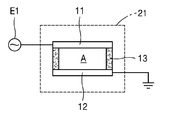
예컨대, 도 1 내지 도 4에 도시된 바와 같이, 상기 반응 본체(10)는, 내부에 용량 결합 플라즈마(CCP: Capacitively Coupled Plasma)가 발생될 수 있도록 제 1 패널(11)과 제 2 패널(12)을 포함하는 구조체일 수 있다.For example, as shown in FIGS. 1 to 4, the
더욱 구체적으로 예를 들면, 도 1 내지 도 4에 도시된 바와 같이, 상기 반응 본체(10)는, 제 1 관통부(W1)가 형성되는 적어도 하나의 상기 제 1 패널(11)과, 제 2 관통부(W2)가 형성되고, 상기 제 1 패널(11)과 일정한 거리로 이격되게 설치되는 적어도 하나의 상기 제 2 패널(12) 및 일측에 유입구(13a)가 형성되고, 타측에 배출구(13b)가 형성되며, 상기 제 1 패널(11)과 상기 제 2 패널(12) 사이에 플라즈마 발생 공간(A)이 형성될 수 있도록 상기 제 1 패널(11)의 테두리부와 상기 제 2 패널(12)의 테두리부 사이에 설치되는 적어도 하나의 절연 벽부(13)를 포함할 수 있다. More specifically, for example, as illustrated in FIGS. 1 to 4, the
여기서, 본 발명의 일부 실시예들에 따른 하이브리드 플라즈마 발생 장치(100)는 상기 반응 본체(10)에 전력을 인가하는 제 1 전원(E1)을 더 포함할 수 있다.Here, the hybrid
이러한, 상기 제 1 전원(E1)은 상기 제 1 패널(11)과 상기 제 2 패널(12) 사이의 상기 플라즈마 발생 공간(A)에서 용량 결합 플라즈마(CCP: Capacitively Coupled Plasma)가 발생될 수 있도록 전위차를 조성하는 RF 파워나 마이크로 웨이브 등의 고주파 전력을 발생시킬 수 있는 전원 장치일 수 있다.The first power source E1 may generate a capacitively coupled plasma (CCP) in the plasma generation space A between the
따라서, 상기 제 1 패널(11)과 상기 제 2 패널(12) 사이에 전하량(Q)는 정전 용량(C)와 전위차(V)의 곱으로 나타낼 수 있고, 이로 인하여 상기 제 1 패널(11)과 상기 제 2 패널(12) 사이의 전자기장에 의해 용량 결합 플라즈마가 생성될 수 있다.Accordingly, the amount of charge Q between the
이 때, 상술된 상기 절연 벽부(13)에 의해 상기 제 1 패널(11)과 상기 제 2 패널(12)은 서로 평행한 판 형상으로 대치될 수 있고, 이로 인하여 플라즈마 밀도가 전영역에 걸쳐서 균일하게 형성될 수 있다.At this time, the
또한, 예컨대, 고주파 전력이 일정한 패스를 통해 균일하게 흐를 수 있도록 상기 제 1 패널(11)과 상기 제 2 패널(12)은 전체적으로 C자 형상을 이루도록 일측에 형성된 개방부에 절연부(16)가 충전될 수 있다.In addition, for example, the
따라서, 예컨대, 전력이 넓은 면적에 인가될 때, 한 부분에만 집중되는 전력 집중 현상을 방지하고, 전체적으로 균일한 플라즈마 밀도를 구현할 수 있다.Therefore, for example, when power is applied to a large area, it is possible to prevent a power concentration phenomenon that is concentrated on only one portion and realize a uniform plasma density as a whole.
또한, 도 1 및 도 3에 도시된 바와 같이, 본 발명의 일부 실시예들에 따른 하이브리드 플라즈마 발생 장치(100)는, 상기 절연 벽부(13)의 유입구(13a)에 설치되는 유입관(14) 및 상기 절연 벽부(13)의 배출구(13b)에 설치되는 배출관(15)을 더 포함할 수 있다.In addition, as shown in Figures 1 and 3, the hybrid
이러한 상기 유입관(14)과 상기 배출관(15)은 상술된 고주파 전력 인가시 전자기장에 영향을 주지 않도록 절연 재질로 이루어지거나 절연 코팅될 수 있다.The
이와 동시에, 예컨대, 도 1 내지 도 4에 도시된 바와 같이, 상기 반응 본체(10)는, 토로이달 형태, 즉 변압기 결합 형태의 리모트 플라즈마 발생 장치(RPG, remote plasma generator)를 이용할 수 있는 것으로서, 내부에 플라즈마 발생 공간이 형성될 수 있도록 전체적으로 속이 빈 중공관 형태로 이루어질 수 있다.At the same time, for example, as shown in FIGS. 1 to 4, the
더욱 구체적으로 예를 들면, 도 1 내지 도 4에 도시된 바와 같이, 상기 반응 본체(10)는 중공형 형상이고, 환형의 플라즈마 방전 루프가 좌측 및 우측 또는 상측 및 하측에 각각 형성되도록 분기된 분기관이 형성될 수 있다.More specifically, for example, as shown in Figures 1 to 4, the
또한, 예컨대, 도 1에 도시된 바와 같이, 상기 반응 본체(10)는, 상기 반응 본체(10)의 일부분에 형성되는 제 1 부분(상부) 및 상기 반응 본체(10)의 타부분에 형성되고, 점화 기전력이 형성되도록 상기 제 1 부분과 대응되게 형성되는 제 2 부분(하부)을 포함할 수 있다.In addition, for example, as shown in FIG. 1, the
여기서, 상기 반응 본체(10)를 상술된 상기 제 1 부분과 상기 제 2 부분, 즉 2 피스로 형성하는 이유는, 상기 반응 본체(10)의 상기 제 1 부분과 상기 제 2 부분 사이에 플라즈마 방전을 점화시키고, 이를 유지시키기 위한 점화 기전력 또는 유지 기전력을 형성하기 위해서 일 수 있다.Here, the reason for forming the
즉, 상기 제 1 부분은 상기 반응 본체(10)의 상부에 형성된 상부 분지관이고, 상기 제 2 부분은 상기 반응 본체(10)의 하부에 형성되는 하부 합지관일 수 있다. 이러한 상기 상부 분지관과 상기 하부 합지관 사이에는, 도시하지 않았지만, 별도의 절연 부재 또는 실링 부재가 설치될 수 있다.That is, the first portion may be an upper branch pipe formed on the upper portion of the
따라서, 공정 가스 또는 세정 가스는 상기 제 1 부분의 입구를 통해 상기 반응 본체(10)로 유입되고, 상기 반응 본체(10)의 내부에서 플라즈마 이온화되어 상기 제 2 부분의 출구를 통해 배출될 수 있다.Accordingly, process gas or cleaning gas may be introduced into the
즉, 본 발명의 하이브리드 플라즈마 발생 장치(100)의 상기 반응 본체(10)는 유입구(13a)로 산소가 유입되고, 배출구(13b)로 오존이 배출되는 오존 발생 용도로 사용될 수 있다. 그러나, 이에 반드시 국한되지 않고, 공정 챔버의 세정 용도로 사용되거나, 또는 공정 가스 공급 용도로도 사용될 수 있다.That is, the
이외에도, 본 발명의 하이브리드 플라즈마 발생 장치(100)는 각종 라디칼을 생성할 수 있는 것으로서, 이에 반드시 국한되지 않는다.In addition, the
한편, 예컨대, 도 1 내지 도 4에 도시된 바와 같이, 상기 마그네틱 코어(20)는, 일차 권선(23)을 이용하여 상기 반응 본체(10) 내부에 변압기 결합 플라즈마(TCP: Transformer Coupled Plasma)가 발생될 수 있도록 상기 반응 본체(10)에 결합되어 상술된 용량 결합 플라즈마와 병합될 수 있는 변압기 결합 플라즈마 발생을 위한 유도기전력을 형성할 수 있다.On the other hand, for example, as shown in Figures 1 to 4, the
더욱 구체적으로 예를 들면, 도 1 내지 도 3에 도시된 바와 같이, 상기 마그네틱 코어(20)는, 상기 제 1 패널(11)의 상기 제 1 관통부(W1)와 상기 제 2 패널(12)의 상기 제 2 관통부(W2)를 관통하고, 상기 제 1 패널(11) 및 상기 제 2 패널(12)의 일부분에 권취되는 적어도 하나의 제 1 코어(21) 및 상기 제 1 패널(11)의 상기 제 1 관통부(W1)와 상기 제 2 패널(12)의 상기 제 2 관통부(W2)를 관통하고, 상기 제 1 패널(11) 및 상기 제 2 패널(12)의 타부분에 권취되는 적어도 하나의 제 2 코어(22)를 포함할 수 있다.More specifically, for example, as illustrated in FIGS. 1 to 3, the
여기서, 본 발명의 일부 실시예들에 따른 하이브리드 플라즈마 발생 장치(100)는 상기 마그네틱 코어(20)에 전력을 인가하는 제 2 전원(E2)을 더 포함할 수 있다.Here, the hybrid
이러한, 상기 제 2 전원(E2)은 상기 반응 본체(10)의 상기 플라즈마 발생 공간(A)에서 변압기 결합 플라즈마(TCP: Transformer Coupled Plasma)가 발생될 수 있도록 유도기전력을 발생시키는 RF 파워나 마이크로 웨이브 등의 고주파 전력을 발생시킬 수 있는 전원 장치일 수 있다.The second power source (E2) is an RF power or microwave that generates an induced electromotive force so that a transformer coupled plasma (TCP) can be generated in the plasma generation space (A) of the reaction body (10). It may be a power supply that can generate high-frequency power, such as.
따라서, 이러한 본 발명의 일부 실시예들에 따른 하이브리드 플라즈마 발생 장치(100)의 작동 과정을 설명하면, 상술된 바와 같이 상기 반응 본체(10)의 상기 제 1 패널(11)과 상기 제 2 패널(12)을 이용하여 용량 결합 플라즈마가 발생되는 동시에, 상기 일차 권선(21)에 의해 상기 마그네틱 코어(20)에 유도기전력이 형성되어 상기 반응 본체(10)에 환형의 플라즈마 방전 루프가 발생되고, 이로 인하여, 상기 반응 본체(10)의 내부에는 2가지 종류의 플라즈마가 병합된 형태로 발생될 수 있다. 여기서, 상기 반응 본체(10)의 내부로 별도의 산소 가스나 기타 세정 가스 또는 반응 가스가 공급될 수 있다.Therefore, when describing the operation process of the hybrid
즉, 상기 반응 본체(10)에 산소 가스가 공급되면, 하이브리드 형태의 플라즈마로 인해 고효율로 높은 밀도의 오존 가스를 생성할 수 있고, 상기 반응 본체(10)에 세정 가스나 공정 가스가 공급되면, 플라즈마 에너지를 인가받아 플라즈마 상태로 여기 되어 각종 공정 챔버로 공급될 수 있다.That is, when oxygen gas is supplied to the
예컨대, 이러한 상기 공정 챔버는, 웨이퍼나 유리 기판 등의 기판(W)을 가공할 수 있는 것으로서, 예를 들어, 포토레지스트를 제거하는 애싱(ashing) 챔버일 수 있고, 절연막을 증착시키도록 구성된 CVD(Chemical Vapor Deposition) 챔버일 수 있고, 인터커넥트 구조들을 형성하기 위해 절연막에 애퍼쳐(aperture)들이나 개구들을 에칭하도록 구성된 에칭 챔버일 수 있다. 또는 장벽(barrier) 막을 증착시키도록 구성된 PVD 챔버일 수 있으며, 금속막을 증착시키도록 구성된 PVD 챔버일 수 있다.For example, the process chamber may be a wafer or a glass substrate, such as a substrate W, and may be, for example, an ashing chamber for removing photoresist, and CVD configured to deposit an insulating film. It may be a (Chemical Vapor Deposition) chamber, or an etch chamber configured to etch apertures or openings in an insulating film to form interconnect structures. Or it may be a PVD chamber configured to deposit a barrier film, or a PVD chamber configured to deposit a metal film.
그러므로, 대면적의 처리 능력을 갖는 확장성이 용이한 변압기 결합 플라즈마와 용량 결합 플라즈마를 복합적으로 발생할 수 있고, 저압 영역에서 고압 영역까지 폭넓은 동작 영역으로 운용이 가능하며, 저압 영역에서도 쉽게 플라즈마 점화를 발생하고 유지하며 고압 영역에서도 반응기 내부 손상 없이 대용량의 플라즈마를 생성할 수 있고, 오존 발생 장치에 적용되어 고효율로 대용량의 오존을 생성할 수 있다. Therefore, a transformer-coupled plasma and a capacitively-coupled plasma that can be easily expanded with a large-area processing capability can be generated in a complex manner, and can be operated in a wide range of operation from a low pressure region to a high pressure region, and easily ignite plasma even in a low pressure region. Can generate and maintain, and generate a large-capacity plasma without damaging the reactor even in a high-pressure region, and can be applied to an ozone generator to generate large-capacity ozone with high efficiency.
도 5는 도 1의 하이브리드 플라즈마 발생 장치의 다른 일례를 나타내는 종단면도이고, 도 6은 도 1의 하이브리드 플라즈마 발생 장치의 또 다른 일례를 나타내는 종단면도이고, 도 7은 도 1의 하이브리드 플라즈마 발생 장치의 또 다른 일례를 나타내는 종단면도이다.5 is a longitudinal sectional view showing another example of the hybrid plasma generator of FIG. 1, FIG. 6 is a longitudinal sectional view showing another example of the hybrid plasma generator of FIG. 1, and FIG. 7 is a hybrid plasma generator of FIG. It is a longitudinal cross-sectional view showing another example.
도 5 내지 도 7에 도시된 바와 같이, 상기 제 1 패널(11)과 상기 제 2 패널(12)의 대향면에 서로 어긋나게 배치되는 도 6의 돌기(T) 또는 도 5 및 도 7의 돌출판(P)이 형성될 수 있다.5 to 7, the protrusions T of FIG. 6 or the protruding plates of FIGS. 5 and 7 disposed to be offset from each other on opposite surfaces of the
따라서, 상기 제 1 패널(11)과 상기 제 2 패널(12)의 표면적을 넓게 하여 플라즈마 밀도를 더욱 향상시킬 수 있고, 오존 가스나 세정 가스나 공정 가스 등 각종 라디칼의 대용량 발생이 가능하다.Therefore, it is possible to further improve the plasma density by increasing the surface area of the
도 8은 본 발명의 일부 다른 실시예들에 따른 하이브리드 플라즈마 발생 장치(200)를 나타내는 부품 분해 사시도이다.8 is an exploded perspective view of a component showing a
도 7 및 도 8에 도시된 바와 같이, 본 발명의 일부 다른 실시예들에 따른 하이브리드 플라즈마 발생 장치(200)는, 상기 제 1 패널(11)은 복수개가 서로 이격되게 적층되는 형상으로 설치되고, 상기 제 2 패널(12)은 상기 제 1 패널(11)들 사이 사이에 복수개가 서로 이격되게 적층되는 형상으로 설치되며, 상기 제 1 패널(11)들이 전기적으로 서로 연결되고, 상기 제 2 패널(12)들이 전기적으로 서로 연결될 수 있도록 각각 연결 회로(C)가 형성될 수 있다.7 and 8, the hybrid
예컨대, 도 7 및 도 8에 도시된 바와 같이, 상기 제 1 패널(11)은 제 1-1 패널(11-1)과 제 1-2 패널(11-2)로 이루어지고, 상기 제 2 패널(12)은 제 2-1 패널(12-1)과 제 2-2 패널(12-2)로 이루어지는 경우, 상기 연결 회로(C)는, 상기 제 1-1 패널(11-1)과 상기 제 1-2 패널(11-2)을 전기적으로 연결하는 제 1 연결 회로(C1) 및 상기 제 2-1 패널(12-1)과 상기 제 2-2 패널(12-2)을 전기적으로 연결하는 제 2 연결 회로(C2)를 포함할 수 있다.For example, as shown in FIGS. 7 and 8, the
따라서, 상기 제 1-1 패널(11-1)과 상기 제 2-1 패널(12-1) 사이에서 제 1 플라즈마 발생 공간이 형성되고, 상기 제 2-1 패널(12-1)과 상기 제 1-2 패널(11-2) 사이에서 제 2 플라즈마 발생 공간이 형성되며, 상기 제 1-2 패널(11-2)과 상기 제 2-2 패널(12-2) 사이에서 제 3 플라즈마 발생 공간이 형성될 수 있다.Accordingly, a first plasma generation space is formed between the 1-1 panel 11-1 and the 2-1 panel 12-1, and the 2-1 panel 12-1 and the first A second plasma generating space is formed between the 1-2 panels 11-2, and a third plasma generating space is formed between the 1-2 panels 11-2 and the 2-2 panels 12-2. It can be formed.
즉, 도 8에 도시된 바와 같이, 상기 유입관(14)을 통해 유입된 가스가 복수개(도면에서는 3개)의 상기 유입구(13a)들로 분기되고, 복수개(도면에서는 3개)의 상기 배출구(13b)들을 통해 배출된 상기 가스가 상기 배출관(15)을 통해 합기되어 배출될 수 있다.That is, as shown in Figure 8, the gas introduced through the
또한, 예컨대, 이러한 경우, 도 7에 도시된 바와 같이, 상기 제 1 코어(21)는, 복수개의 상기 제 1 패널(11)들, 즉 상기 제 1-1 패널(11-1) 및 상기 제 1-2 패널(11-2)의 일부분과 복수개의 상기 제 2 패널(12)들, 즉 상기 제 2-1 패널(12-1) 및 상기 제 2-2 패널(12-2)의 일부분을 감싸는 형상으로 권취될 수 있다.In addition, for example, in this case, as shown in FIG. 7, the
도 9는 도 1의 하이브리드 플라즈마 발생 장치의 또 다른 일례를 나타내는 종단면도이고, 도 10은 본 발명의 일부 또 다른 실시예들에 따른 하이브리드 플라즈마 발생 장치(300)를 나타내는 부품 분해 사시도이다.9 is a longitudinal cross-sectional view illustrating another example of the hybrid plasma generator of FIG. 1, and FIG. 10 is an exploded perspective view of a component of the
예컨대, 도 9 및 도 10에 도시된 바와 같이, 상기 제 1 패널(11)은 제 1-1 패널(11-1)과 제 1-2 패널(11-2)로 이루어지고, 상기 제 2 패널(12)은 제 2-1 패널(12-1)과 제 2-2 패널(12-2)로 이루어지는 경우, 또 다른 연결 방법으로서, 상기 연결 회로(C)는, 상기 제 1-1 패널(11-1)과 상기 제 2-1 패널(12-1)을 연결하는 제 3 연결 회로(C3), 상기 2-1 패널(12-1)과 상기 제 1-2 패널(11-2)을 전기적으로 연결하는 제 4 연결 회로(C4) 및 상기 제 1-2 패널(11-2)과 상기 제 2-2 패널(12-2)을 전기적으로 연결하는 제 5 연결 회로(C5)를 포함할 수 있다.For example, as illustrated in FIGS. 9 and 10, the
따라서, 이러한 상기 제 3 연결 회로(C3), 상기 제 4 연결 회로(C4) 및 상기 제 5 연결 회로(C5)를 이용하여 일종의 소용돌이치는 하나의 코일 형태의 전류를 형성하여 플라즈마 발생 공간을 형성하는 것도 가능하다. 그러나, 이러한 상기 연결 회로들은 도면에 국한되지 않고 매우 다양한 방법으로 회로를 형성할 수 있다.Accordingly, by using the third connection circuit C3, the fourth connection circuit C4, and the fifth connection circuit C5, a kind of swirling coil current is formed to form a plasma generation space. It is also possible. However, these connection circuits are not limited to the drawings and can be formed in a wide variety of ways.
그러나, 이에 반드시 국한되지 않는 것으로서, 상기 연결 회로는 생략되는 것도 가능하다.However, it is not necessarily limited to this, and the connection circuit may be omitted.
도 11은 본 발명의 일부 또 다른 실시예들에 따른 하이브리드 플라즈마 발생 장치(400)를 나타내는 부품 분해 사시도이다.11 is an exploded perspective view showing a part of a
도 11에 도시된 바와 같이, 상기 제 1 코어(21)는 상기 제 1 패널(11) 및 상기 제 2 패널(12)의 일부분, 즉 환형의 상기 반응 본체(10)의 좌측에 복수개(도면에서는 3개)가 등각도로 배치될 수 있고, 상기 제 2 코어(22)는 상기 제 1 패널(11) 및 상기 제 2 패널(12)의 타부분, 즉 환형의 상기 반응 본체(10)의 우측에 복수개(도면에서는 3개)가 등각도로 배치될 수 있다.As shown in FIG. 11, a plurality of
따라서, 본 발명의 기술적 사상에 따르면, 상술된 바와 같이, 적층되는 패널들의 개수를 늘려서 용량 결합 플라즈마의 강도와 세기를 쉽게 증대시킬 수 있는 동시에, 마그네틱 코어의 개수를 늘려서 변압기 결합 플라즈마의 강도와 세기 역시 쉽게 증대시킬 수 있고, 이들 플라즈마의 하이브리드 병합으로 대용량 라디칼 발생이 가능하다.Therefore, according to the technical idea of the present invention, as described above, it is possible to easily increase the strength and strength of the capacitively coupled plasma by increasing the number of stacked panels, while simultaneously increasing the strength and intensity of the transformer coupled plasma by increasing the number of magnetic cores. It can also be easily increased, and the hybrid merging of these plasmas can generate large-scale radicals.
본 발명은 도면에 도시된 실시예를 참고로 설명되었으나 이는 예시적인 것에 불과하며, 당해 기술분야에서 통상의 지식을 가진 자라면 이로부터 다양한 변형 및 균등한 다른 실시예가 가능하다는 점을 이해할 것이다. 따라서 본 발명의 진정한 기술적 보호 범위는 첨부된 특허청구범위의 기술적 사상에 의하여 정해져야 할 것이다.The present invention has been described with reference to the embodiments shown in the drawings, but these are merely exemplary, and those skilled in the art will understand that various modifications and equivalent other embodiments are possible therefrom. Therefore, the true technical protection scope of the present invention should be determined by the technical spirit of the appended claims.
10: 반응 본체
11: 제 1 패널
11-1: 제 1-1 패널
11-2: 제 1-2 패널
12: 제 2 패널
12-1: 제 2-1 패널
12-2: 제 2-2 패널
13: 절연 벽부
13a: 유입구
13b: 배출구
A: 플라즈마 발생 공간
14: 유입관
15: 배출관
16: 절연부
T: 돌기
P: 돌출판
20: 마그네틱 코어
21: 제 1 코어
22: 제 2 코어
W1: 제 1 관통부
W2: 제 2 관통부
C: 연결 회로
C1: 제 1 연결 회로
C2: 제 2 연결 회로
C3: 제 3 연결 회로
C4: 제 4 연결 회로
C5: 제 5 연결 회로
E1: 제 1 전원
E2: 제 2 전원
100, 200, 300, 400: 하이브리드 플라즈마 발생 장치10: reaction body
11: 1st panel
11-1: 1-1 panel
11-2: Panel 1-2
12: second panel
12-1: 2-1 panel
12-2: 2-2 panel
13: Insulation wall
13a: inlet
13b: outlet
A: plasma generation space
14: inlet pipe
15: discharge pipe
16: Insulation
T: Turn
P: protrusion plate
20: magnetic core
21: first core
22: Second core
W1: first penetration
W2: second penetration
C: Connection circuit
C1: first connection circuit
C2: 2nd connection circuit
C3: 3rd connection circuit
C4: 4th connection circuit
C5: 5th connection circuit
E1: first power
E2: Second power
100, 200, 300, 400: hybrid plasma generator
Claims (12)
일차 권선을 이용하여 상기 반응 본체 내부에 변압기 결합 플라즈마(TCP: Transformer Coupled Plasma)가 발생될 수 있도록 상기 반응 본체에 결합되는 마그네틱 코어;
를 포함하는, 하이브리드 플라즈마 발생 장치.A reaction body including a first panel and a second panel so that a capacitively coupled plasma (CCP) can be generated therein; And
A magnetic core coupled to the reaction body to generate a transformer coupled plasma (TCP) inside the reaction body using a primary winding;
A hybrid plasma generating device comprising a.
상기 반응 본체는,
제 1 관통부가 형성되는 적어도 하나의 상기 제 1 패널;
제 2 관통부가 형성되고, 상기 제 1 패널과 일정한 거리로 이격되게 설치되는 적어도 하나의 상기 제 2 패널; 및
일측에 유입구가 형성되고, 타측에 배출구가 형성되며, 상기 제 1 패널과 상기 제 2 패널 사이에 플라즈마 발생 공간이 형성될 수 있도록 상기 제 1 패널의 테두리부와 상기 제 2 패널의 테두리부 사이에 설치되는 적어도 하나의 절연 벽부;
를 포함하는, 하이브리드 플라즈마 발생 장치.According to claim 1,
The reaction body,
At least one first panel on which a first through portion is formed;
At least one second panel formed with a second through portion and spaced apart from the first panel at a constant distance; And
An inlet port is formed on one side, an outlet port is formed on the other side, and an edge portion of the first panel and an edge portion of the second panel are formed so that a plasma generation space is formed between the first panel and the second panel. At least one insulating wall portion to be installed;
A hybrid plasma generating device comprising a.
상기 제 1 패널과 상기 제 2 패널은 전체적으로 C자 형상을 이루도록 일측에 형성된 개방부에 절연부가 충전되는, 하이브리드 플라즈마 발생 장치.According to claim 2,
The first panel and the second panel is a hybrid plasma generator, the insulating portion is filled in the opening formed on one side to form a C-shape as a whole.
상기 절연 벽부의 유입구에 설치되는 유입관; 및
상기 절연 벽부의 배출구에 설치되는 배출관;
을 더 포함하는, 하이브리드 플라즈마 발생 장치.According to claim 2,
An inlet pipe installed at the inlet of the insulating wall portion; And
A discharge pipe installed at the outlet of the insulating wall portion;
Further comprising, a hybrid plasma generating device.
상기 제 1 패널과 상기 제 2 패널의 대향면에 서로 어긋나게 배치되는 돌기 또는 돌출판이 형성되는, 하이브리드 플라즈마 발생 장치.According to claim 2,
A hybrid plasma generating device in which projections or protrusions disposed on the opposite surfaces of the first panel and the second panel are disposed to be offset from each other.
상기 제 1 패널은 복수개가 서로 이격되게 적층되는 형상으로 설치되고, 상기 제 2 패널은 상기 제 1 패널들 사이 사이에 복수개가 적층되는 형상으로 설치되며,
상기 제 1 패널들 또는 상기 제 1 패널과 상기 제 2 패널이 전기적으로 서로 연결되고, 상기 제 2 패널들 또는 상기 제 2 패널과 상기 제 1 패널들이 전기적으로 서로 연결될 수 있도록 각각 연결 회로가 형성되는, 하이브리드 플라즈마 발생 장치.According to claim 2,
The first panel is installed in a shape in which a plurality of layers are spaced apart from each other, and the second panel is installed in a shape in which a plurality of layers are stacked between the first panels,
A connection circuit is formed so that the first panels or the first panel and the second panel are electrically connected to each other, and the second panels or the second panel and the first panels are electrically connected to each other. , Hybrid plasma generator.
상기 마그네틱 코어는,
상기 제 1 패널의 상기 제 1 관통부와 상기 제 2 패널의 상기 제 2 관통부를 관통하고, 상기 제 1 패널 및 상기 제 2 패널의 일부분에 권취되는 적어도 하나의 제 1 코어; 및
상기 제 1 패널의 상기 제 1 관통부와 상기 제 2 패널의 상기 제 2 관통부를 관통하고, 상기 제 1 패널 및 상기 제 2 패널의 타부분에 권취되는 적어도 하나의 제 2 코어;
를 포함하는, 하이브리드 플라즈마 발생 장치.According to claim 2,
The magnetic core,
At least one first core passing through the first through portion of the first panel and the second through portion of the second panel, and wound around a portion of the first panel and the second panel; And
At least one second core passing through the first through portion of the first panel and the second through portion of the second panel, and wound around the other portions of the first panel and the second panel;
A hybrid plasma generating device comprising a.
상기 제 1 코어는 상기 제 1 패널 및 상기 제 2 패널의 일부분에 복수개가 배치되고, 상기 제 2 코어는 상기 제 1 패널 및 상기 제 2 패널의 타부분에 복수개가 배치되는, 하이브리드 플라즈마 발생 장치.The method of claim 7,
A hybrid plasma generating apparatus in which a plurality of the first cores are disposed on a portion of the first panel and the second panel, and a plurality of the second cores are disposed on other portions of the first panel and the second panel.
상기 제 1 코어는, 복수개의 상기 제 1 패널들의 일부분과 복수개의 상기 제 2 패널들의 일부분을 감싸는 형상으로 권취되는, 하이브리드 플라즈마 발생 장치.The method of claim 7,
The first core, the hybrid plasma generating apparatus is wound in a shape surrounding a portion of the plurality of the first panel and a portion of the plurality of the second panel.
상기 유입관을 통해 유입된 가스가 복수개의 상기 유입구들로 분기되고, 복수개의 상기 배출구들을 통해 배출된 상기 가스가 상기 배출관을 통해 합기되어 배출되는, 하이브리드 플라즈마 발생 장치.The method of claim 9,
A hybrid plasma generating apparatus in which gas introduced through the inlet pipe is branched into a plurality of the inlets, and the gas discharged through the plurality of outlets is combined and discharged through the outlet pipe.
상기 반응 본체에 전력을 인가하는 제 1 전원; 및
상기 마그네틱 코어의 상기 일차 권선에 전력을 인가하는 제 2 전원;
을 더 포함하는, 하이브리드 플라즈마 발생 장치. According to claim 1,
A first power source for applying electric power to the reaction body; And
A second power source that applies electric power to the primary winding of the magnetic core;
Further comprising, a hybrid plasma generating device.
상기 반응 본체는 유입구로 산소가 유입되고, 배출구로 오존이 배출되는 오존 발생용인, 하이브리드 플라즈마 발생 장치.According to claim 1,
The reaction body is a hybrid plasma generator for ozone generation, in which oxygen is introduced into the inlet and ozone is discharged through the outlet.
Priority Applications (1)
| Application Number | Priority Date | Filing Date | Title |
|---|---|---|---|
| KR1020180131705A KR20200048984A (en) | 2018-10-31 | 2018-10-31 | Hybrid plasma generator |
Applications Claiming Priority (1)
| Application Number | Priority Date | Filing Date | Title |
|---|---|---|---|
| KR1020180131705A KR20200048984A (en) | 2018-10-31 | 2018-10-31 | Hybrid plasma generator |
Publications (1)
| Publication Number | Publication Date |
|---|---|
| KR20200048984A true KR20200048984A (en) | 2020-05-08 |
Family
ID=70677019
Family Applications (1)
| Application Number | Title | Priority Date | Filing Date |
|---|---|---|---|
| KR1020180131705A KR20200048984A (en) | 2018-10-31 | 2018-10-31 | Hybrid plasma generator |
Country Status (1)
| Country | Link |
|---|---|
| KR (1) | KR20200048984A (en) |
Cited By (1)
| Publication number | Priority date | Publication date | Assignee | Title |
|---|---|---|---|---|
| JP2023094503A (en) * | 2021-12-23 | 2023-07-05 | 明遠精密科技股▲分▼有限公司 | Hybrid plasma source |
-
2018
- 2018-10-31 KR KR1020180131705A patent/KR20200048984A/en not_active Application Discontinuation
Cited By (2)
| Publication number | Priority date | Publication date | Assignee | Title |
|---|---|---|---|---|
| JP2023094503A (en) * | 2021-12-23 | 2023-07-05 | 明遠精密科技股▲分▼有限公司 | Hybrid plasma source |
| US11895765B2 (en) | 2021-12-23 | 2024-02-06 | Finesse Technology Co., Ltd. | Hybrid plasma source and operation method thereof |
Similar Documents
| Publication | Publication Date | Title |
|---|---|---|
| KR100486712B1 (en) | Inductively coupled plasma generating apparatus with double layer coil antenna | |
| KR101659594B1 (en) | High efficiency plasma source | |
| JP4388020B2 (en) | Semiconductor plasma processing apparatus and method | |
| US6849857B2 (en) | Beam processing apparatus | |
| KR101094124B1 (en) | Antenna for producing uniform process rates | |
| US20100065215A1 (en) | Plasma generating apparatus | |
| US20050183668A1 (en) | Plasma antenna | |
| US20100098882A1 (en) | Plasma source for chamber cleaning and process | |
| KR101496841B1 (en) | Compound plasma reactor | |
| TWI601181B (en) | System for the processing of an object by plasma, selective plasma processing process of a composite object, and etched composite object obtained by the same process | |
| KR101017101B1 (en) | Inductively coupled plasma antenna | |
| KR20120004040A (en) | Plasma generating apparatus | |
| US6909086B2 (en) | Neutral particle beam processing apparatus | |
| KR20200048984A (en) | Hybrid plasma generator | |
| KR101881537B1 (en) | Plasma chamber for improved gas decomposition efficiency | |
| US7060931B2 (en) | Neutral beam source having electromagnet used for etching semiconductor device | |
| KR102619010B1 (en) | Plasma chamber to change the installation location of the ferrite core | |
| KR20090083253A (en) | Inductive plasma chamber having multi discharge tube bridge | |
| KR101016573B1 (en) | Plasma generation apparatus | |
| KR101680707B1 (en) | Transformer coupled plasma generator having first winding to ignite and sustain a plasma | |
| KR20170134012A (en) | Plasma chamber using the chamber block possible plasma ignition | |
| KR20170139759A (en) | Plasma chamber having gas distribution plate for uniform gas distribution | |
| KR101039232B1 (en) | High-density plasma generation apparatus | |
| KR20210155622A (en) | Plasma reaction apparatus | |
| KR100731993B1 (en) | Plasma source internal discharging bridge |
Legal Events
| Date | Code | Title | Description |
|---|---|---|---|
| A201 | Request for examination | ||
| E902 | Notification of reason for refusal |