KR20200048955A - Power latch apparatus - Google Patents
Power latch apparatus Download PDFInfo
- Publication number
- KR20200048955A KR20200048955A KR1020180131650A KR20180131650A KR20200048955A KR 20200048955 A KR20200048955 A KR 20200048955A KR 1020180131650 A KR1020180131650 A KR 1020180131650A KR 20180131650 A KR20180131650 A KR 20180131650A KR 20200048955 A KR20200048955 A KR 20200048955A
- Authority
- KR
- South Korea
- Prior art keywords
- claw
- cam
- pole
- rod
- release
- Prior art date
Links
Images


Classifications
-
- E—FIXED CONSTRUCTIONS
- E05—LOCKS; KEYS; WINDOW OR DOOR FITTINGS; SAFES
- E05B—LOCKS; ACCESSORIES THEREFOR; HANDCUFFS
- E05B85/00—Details of vehicle locks not provided for in groups E05B77/00 - E05B83/00
- E05B85/20—Bolts or detents
- E05B85/24—Bolts rotating about an axis
- E05B85/26—Cooperation between bolts and detents
-
- E—FIXED CONSTRUCTIONS
- E05—LOCKS; KEYS; WINDOW OR DOOR FITTINGS; SAFES
- E05B—LOCKS; ACCESSORIES THEREFOR; HANDCUFFS
- E05B81/00—Power-actuated vehicle locks
- E05B81/24—Power-actuated vehicle locks characterised by constructional features of the actuator or the power transmission
- E05B81/32—Details of the actuator transmission
-
- E—FIXED CONSTRUCTIONS
- E05—LOCKS; KEYS; WINDOW OR DOOR FITTINGS; SAFES
- E05B—LOCKS; ACCESSORIES THEREFOR; HANDCUFFS
- E05B81/00—Power-actuated vehicle locks
- E05B81/02—Power-actuated vehicle locks characterised by the type of actuators used
- E05B81/04—Electrical
- E05B81/06—Electrical using rotary motors
-
- E—FIXED CONSTRUCTIONS
- E05—LOCKS; KEYS; WINDOW OR DOOR FITTINGS; SAFES
- E05B—LOCKS; ACCESSORIES THEREFOR; HANDCUFFS
- E05B81/00—Power-actuated vehicle locks
- E05B81/12—Power-actuated vehicle locks characterised by the function or purpose of the powered actuators
- E05B81/16—Power-actuated vehicle locks characterised by the function or purpose of the powered actuators operating on locking elements for locking or unlocking action
-
- E—FIXED CONSTRUCTIONS
- E05—LOCKS; KEYS; WINDOW OR DOOR FITTINGS; SAFES
- E05B—LOCKS; ACCESSORIES THEREFOR; HANDCUFFS
- E05B81/00—Power-actuated vehicle locks
- E05B81/12—Power-actuated vehicle locks characterised by the function or purpose of the powered actuators
- E05B81/18—Power-actuated vehicle locks characterised by the function or purpose of the powered actuators to effect movement of a bolt or bolts
-
- E—FIXED CONSTRUCTIONS
- E05—LOCKS; KEYS; WINDOW OR DOOR FITTINGS; SAFES
- E05B—LOCKS; ACCESSORIES THEREFOR; HANDCUFFS
- E05B81/00—Power-actuated vehicle locks
- E05B81/24—Power-actuated vehicle locks characterised by constructional features of the actuator or the power transmission
- E05B81/26—Output elements
- E05B81/30—Rotary elements
-
- E—FIXED CONSTRUCTIONS
- E05—LOCKS; KEYS; WINDOW OR DOOR FITTINGS; SAFES
- E05B—LOCKS; ACCESSORIES THEREFOR; HANDCUFFS
- E05B81/00—Power-actuated vehicle locks
- E05B81/24—Power-actuated vehicle locks characterised by constructional features of the actuator or the power transmission
- E05B81/32—Details of the actuator transmission
- E05B81/34—Details of the actuator transmission of geared transmissions
-
- E—FIXED CONSTRUCTIONS
- E05—LOCKS; KEYS; WINDOW OR DOOR FITTINGS; SAFES
- E05B—LOCKS; ACCESSORIES THEREFOR; HANDCUFFS
- E05B81/00—Power-actuated vehicle locks
- E05B81/24—Power-actuated vehicle locks characterised by constructional features of the actuator or the power transmission
- E05B81/32—Details of the actuator transmission
- E05B81/42—Cams
-
- E—FIXED CONSTRUCTIONS
- E05—LOCKS; KEYS; WINDOW OR DOOR FITTINGS; SAFES
- E05B—LOCKS; ACCESSORIES THEREFOR; HANDCUFFS
- E05B81/00—Power-actuated vehicle locks
- E05B81/12—Power-actuated vehicle locks characterised by the function or purpose of the powered actuators
- E05B81/14—Power-actuated vehicle locks characterised by the function or purpose of the powered actuators operating on bolt detents, e.g. for unlatching the bolt
-
- E—FIXED CONSTRUCTIONS
- E05—LOCKS; KEYS; WINDOW OR DOOR FITTINGS; SAFES
- E05B—LOCKS; ACCESSORIES THEREFOR; HANDCUFFS
- E05B81/00—Power-actuated vehicle locks
- E05B81/12—Power-actuated vehicle locks characterised by the function or purpose of the powered actuators
- E05B81/20—Power-actuated vehicle locks characterised by the function or purpose of the powered actuators for assisting final closing or for initiating opening
-
- E—FIXED CONSTRUCTIONS
- E05—LOCKS; KEYS; WINDOW OR DOOR FITTINGS; SAFES
- E05Y—INDEXING SCHEME RELATING TO HINGES OR OTHER SUSPENSION DEVICES FOR DOORS, WINDOWS OR WINGS AND DEVICES FOR MOVING WINGS INTO OPEN OR CLOSED POSITION, CHECKS FOR WINGS AND WING FITTINGS NOT OTHERWISE PROVIDED FOR, CONCERNED WITH THE FUNCTIONING OF THE WING
- E05Y2900/00—Application of doors, windows, wings or fittings thereof
- E05Y2900/50—Application of doors, windows, wings or fittings thereof for vehicles
- E05Y2900/53—Application of doors, windows, wings or fittings thereof for vehicles characterised by the type of wing
- E05Y2900/531—Doors
-
- E—FIXED CONSTRUCTIONS
- E05—LOCKS; KEYS; WINDOW OR DOOR FITTINGS; SAFES
- E05Y—INDEXING SCHEME RELATING TO HINGES OR OTHER SUSPENSION DEVICES FOR DOORS, WINDOWS OR WINGS AND DEVICES FOR MOVING WINGS INTO OPEN OR CLOSED POSITION, CHECKS FOR WINGS AND WING FITTINGS NOT OTHERWISE PROVIDED FOR, CONCERNED WITH THE FUNCTIONING OF THE WING
- E05Y2900/00—Application of doors, windows, wings or fittings thereof
- E05Y2900/50—Application of doors, windows, wings or fittings thereof for vehicles
- E05Y2900/53—Application of doors, windows, wings or fittings thereof for vehicles characterised by the type of wing
- E05Y2900/546—Tailgates
Abstract
Description
본 발명은 차량의 파워 시스템에 사용되는 파워 랫치 장치에 관한 것이다.The present invention relates to a power latch device used in a vehicle power system.
자동차의 파워 시스템(도어, 후드, 테일게이트, 트렁크 등)에 사용되는 랫치 장치의 경우, 열림(릴리즈)과 닫힘(신칭)을 자동으로 구현하기 위해, 릴리즈 모터와 신칭 모터를 각각 구비하여, 별도의 동작을 수행했다. 릴리즈 동작을 위해서는 릴리즈 모터가 사용되고 신칭 모터가 구동을 정지하며, 신칭 동작을 위해서는 신칭 모터가 사용되고 릴리즈 모터가 구동을 정지하는 식이다.In the case of a latch device used in a vehicle's power system (door, hood, tailgate, trunk, etc.), a release motor and a new motor are provided separately to provide automatic opening (release) and closing (singing). The operation was performed. The release motor is used for release operation, the new motor stops driving, and the new motor is used for new operation, and the release motor stops driving.
이러한 기존의 랫치 장치는, 각 모터가 별도로 구성되어, 전체 랫치 장치의 크기가 크고, 중량이 무거우며, 부품의 개수가 많이 필요해 원가부담이 생기고, 부품 간의 결합되거나 접촉하는 부분이 다수 형성되어 고장의 염려가 있었다.In the conventional latch device, each motor is separately configured, the size of the entire latch device is large, the weight is heavy, and a large number of parts is required, resulting in cost burden. There were concerns.
본 발명은 이와 같은 문제들을 해결하기 위해 안출된 것으로서, 릴리즈 동작과 신칭 동작이 단일 구동부로 이루어지는, 차량에 사용되는 파워 랫치 장치를 제공한다.The present invention has been devised to solve these problems, and provides a power latch device used in a vehicle in which a release operation and a new operation are made of a single driving unit.
본 발명의 실시예에 따른 파워 랫치 장치는, 캠 축에 회전 가능하게 연결되고, 캠 홈을 구비하는 로터리 캠; 상기 캠 홈에 슬라이딩 가능하게 연결되어, 로터리 캠의 회전에 따라 상기 캠 홈에 의해 가압되어 이동하는 전달 로드; 상기 전달 로드가 회전 가능하게 연결됨으로써 상기 전달 로드의 이동에 의해 가압되어 클로 축을 중심으로 회전하고, 스트라이커의 이동을 제한하는 신칭 동작시 내부로 진입하는 상기 스트라이커를 걸어서 이동을 제한하는 클로 홈을 구비하는 클로; 및 상기 클로의 외측면에 접촉하여, 상기 스트라이커가 상기 클로 홈으로부터 이탈하는 릴리즈 동작을 수행하는 방향인 릴리즈 방향으로 상기 클로가 회전하는 것을 차단하거나, 상기 로터리 캠에 의해 가압되어 폴 축을 중심으로 회전함에 따라 상기 클로의 외측면으로부터 이격되어, 상기 릴리즈 방향으로 상기 클로가 회전하는 것을 허용하는 폴을 포함한다.Power latch device according to an embodiment of the present invention, the rotary cam is rotatably connected to the cam shaft, the rotary cam having a cam groove; A transmission rod slidably connected to the cam groove and pressed and moved by the cam groove according to the rotation of the rotary cam; The transfer rod is rotatably connected to be pressurized by the movement of the transfer rod to rotate about the claw axis, and has a claw groove to restrict movement by hooking the striker entering into the inside during a new operation to limit the movement of the striker Claw to do; And contacting the outer surface of the claw to prevent the claw from rotating in the release direction, which is a direction in which the striker performs a release operation deviating from the claw groove, or is pressed by the rotary cam to rotate about the pole axis And a pawl spaced apart from the outer surface of the claw, allowing the claw to rotate in the release direction.
이에 따라, 하나의 구동부를 이용해 선택적으로 릴리즈와 신칭을 수행할 수 있다.Accordingly, it is possible to selectively release and name using one driving unit.
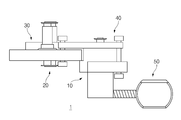
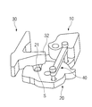
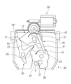
도 1은 본 발명의 일 실시예에 따른 파워 랫치 장치의 사시도이다.
도 2는 본 발명의 일 실시예에 따른 파워 랫치 장치의 측면도이다.
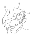
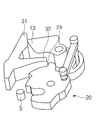
도 3은 본 발명의 일 실시예에 따른 파워 랫치 장치의 분해사시도이다.
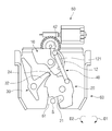
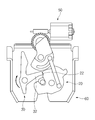
도 4는 본 발명의 일 실시예에 따른 파워 랫치 장치의 릴리즈 상태를 도시한 평면도이다.
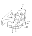
도 5는 본 발명의 일 실시예에 따른 파워 랫치 장치의 릴리즈 상태를 도시한 사시도이다.
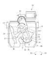
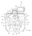
도 6은 본 발명의 일 실시예에 따른 파워 랫치 장치의 1단 락 상태를 도시한 평면도이다.
도 7은 본 발명의 일 실시예에 따른 파워 랫치 장치의 1단 락 상태를 도시한 사시도이다.
도 8은 본 발명의 일 실시예에 따른 파워 랫치 장치의 신칭 동작을 도시한 평면도이다.
도 9는 본 발명의 일 실시예에 따른 파워 랫치 장치의 신칭 동작을 도시한 사시도이다.
도 10은 본 발명의 일 실시예에 따른 파워 랫치 장치의 신칭 상태를 고정하기 위해 폴이 움직이는 상황을 도시한 평면도이다.
도 11은 본 발명의 일 실시예에 따른 파워 랫치 장치의 신칭 상태를 고정하기 위해 폴이 움직이는 상황을 도시한 사시도이다.
도 12는 본 발명의 일 실시예에 따른 파워 랫치 장치의 신칭 상태에서 로터리 캠이 본래 위치로 복귀하는 상황을 도시한 평면도이다.
도 13은 본 발명의 일 실시예에 따른 파워 랫치 장치의 신칭 상태에서 로터리 캠이 본래 위치로 복귀하는 상황을 도시한 사시도이다.
도 14는 본 발명의 일 실시예에 따른 파워 랫치 장치의 릴리즈 동작을 위해 로터리 캠이 회전하는 상황을 도시한 평면도이다.
도 15는 본 발명의 일 실시예에 따른 파워 랫치 장치의 릴리즈 동작을 위해 로터리 캠이 회전하는 상황을 도시한 사시도이다.
도 16은 본 발명의 일 실시예에 따른 파워 랫치 장치의 클로가 회전하여 중간 단계에 이르는 상황을 도시한 평면도이다.
도 17은 본 발명의 일 실시예에 따른 파워 랫치 장치의 클로가 회전하여 중간 단계에 이르는 상황을 도시한 사시도이다.
도 18은 본 발명의 일 실시예에 따른 파워 랫치 장치의 릴리즈 동작이 이루어지는 상황을 도시한 평면도이다.
도 19는 본 발명의 일 실시예에 따른 파워 랫치 장치의 릴리즈 동작이 이루어지는 상황을 도시한 사시도이다.
도 20은 본 발명의 일 실시예에 따른 파워 랫치 장치의 릴리즈 상태에서 로터리 캠이 본래 위치로 복귀하는 상황을 도시한 평면도이다.1 is a perspective view of a power latch device according to an embodiment of the present invention.
2 is a side view of a power latch device according to an embodiment of the present invention.
3 is an exploded perspective view of a power latch device according to an embodiment of the present invention.
4 is a plan view showing a release state of a power latch device according to an embodiment of the present invention.
5 is a perspective view showing a release state of a power latch device according to an embodiment of the present invention.
6 is a plan view showing a one-stage lock state of the power latch device according to an embodiment of the present invention.
7 is a perspective view showing a one-lock state of the power latch device according to an embodiment of the present invention.
8 is a plan view showing a new operation of the power latch device according to an embodiment of the present invention.
9 is a perspective view showing a new operation of the power latch device according to an embodiment of the present invention.
10 is a plan view showing a situation in which the pole moves to fix the nominal state of the power latch device according to an embodiment of the present invention.
11 is a perspective view showing a situation in which the pole moves to fix the nominal state of the power latch device according to an embodiment of the present invention.
12 is a plan view showing a situation in which the rotary cam returns to its original position in the nominal state of the power latch device according to an embodiment of the present invention.
13 is a perspective view showing a situation in which the rotary cam returns to its original position in the nominal state of the power latch device according to an embodiment of the present invention.
14 is a plan view showing a situation in which the rotary cam rotates for the release operation of the power latch device according to an embodiment of the present invention.
15 is a perspective view showing a situation in which the rotary cam rotates for the release operation of the power latch device according to an embodiment of the present invention.
16 is a plan view showing a situation in which the claw of the power latch device according to an embodiment reaches an intermediate stage by rotating.
17 is a perspective view showing a situation in which the claw of the power latch device according to an embodiment of the present invention rotates to an intermediate stage.
18 is a plan view showing a situation in which the release operation of the power latch device according to an embodiment of the present invention is made.
19 is a perspective view showing a situation in which the release operation of the power latch device according to an embodiment of the present invention is made.
20 is a plan view showing a situation in which the rotary cam returns to its original position in the released state of the power latch device according to an embodiment of the present invention.
이하, 본 발명의 일부 실시예들을 예시적인 도면을 통해 상세하게 설명한다. 각 도면의 구성요소들에 참조부호를 부가함에 있어서, 동일한 구성요소들에 대해서는 비록 다른 도면상에 표시되더라도 가능한 한 동일한 부호를 가지도록 하고 있음에 유의해야 한다. 또한, 본 발명의 실시예를 설명함에 있어, 관련된 공지 구성 또는 기능에 대한 구체적인 설명이 본 발명의 실시예에 대한 이해를 방해한다고 판단되는 경우에는 그 상세한 설명은 생략한다.Hereinafter, some embodiments of the present invention will be described in detail through exemplary drawings. It should be noted that in adding reference numerals to the components of each drawing, the same components have the same reference numerals as possible even though they are displayed on different drawings. In addition, in describing the embodiments of the present invention, when it is determined that detailed descriptions of related well-known configurations or functions interfere with the understanding of the embodiments of the present invention, detailed descriptions thereof will be omitted.
또한, 본 발명의 실시예의 구성 요소를 설명하는 데 있어서, 제 1, 제 2, A, B, (a), (b) 등의 용어를 사용할 수 있다. 이러한 용어는 그 구성 요소를 다른 구성 요소와 구별하기 위한 것일 뿐, 그 용어에 의해 해당 구성 요소의 본질이나 차례 또는 순서 등이 한정되지 않는다. 어떤 구성 요소가 다른 구성요소에 "연결", "결합" 또는 "접속"된다고 기재된 경우, 그 구성 요소는 그 다른 구성요소에 직접적으로 연결되거나 접속될 수 있지만, 각 구성 요소 사이에 또 다른 구성 요소가 "연결", "결합" 또는 "접속"될 수도 있다고 이해되어야 할 것이다.In addition, in describing the components of the embodiments of the present invention, terms such as first, second, A, B, (a), (b), and the like can be used. These terms are only for distinguishing the component from other components, and the nature, order, or order of the component is not limited by the term. When a component is described as being "connected", "coupled" or "connected" to another component, that component may be directly connected to or connected to the other component, but another component between each component It should be understood that may be "connected", "coupled" or "connected".
도 1은 본 발명의 일 실시예에 따른 파워 랫치 장치(1)의 사시도이다. 도 2는 본 발명의 일 실시예에 따른 파워 랫치 장치(1)의 측면도이다. 도 3은 본 발명의 일 실시예에 따른 파워 랫치 장치(1)의 분해사시도이다.1 is a perspective view of a
도면을 참조하면, 본 발명의 일 실시예에 따른 파워 랫치 장치(1)는, 로터리 캠(10), 전달 로드(40), 클로(20) 및 폴(30)을 포함하고, 구동부(50)와 하우징(60)을 더 포함할 수 있다. 본 발명의 명세서에서 신칭 동작이란 스트라이커(S)의 이동을 제한하는 동작을 의미하고, 릴리즈 동작이란 스트라이커(S)의 이동을 허용하는 동작을 의미한다. 이러한 릴리즈 동작을 수행하기 위한 회전방향을 릴리즈 방향(D2, 도 4 참조)이라 하고, 그 반대방향을 신칭 방향(D1, 도 4 참조)이라 한다. 본 발명의 명세서의 평면도에서는 릴리즈 방향(D2)을 시계 반대방향으로 도시하였고, 신칭 방향(D1)을 시계방향으로 도시하였으나, 그 방향은 이에 제한되지 않는다.Referring to the drawings, the
본 발명의 일 실시예에 따른 파워 랫치 장치(1)의 구성요소들은 하우징(60)에 결합되거나 수용될 수 있다. 하우징(60)은 파워 랫치 장치(1)의 뼈대가 될 수 있는 구성요소로, 스트라이커(S)가 삽입될 수 있는 요입(凹入)된 하우징 홈(61)을 일측에 가질 수 있다. 스트라이커(S)란, 본 발명의 파워 랫치 장치(1)가 고정되거나 고정을 해제하고자 하는 대상물이다.Components of the
로터리 캠(10)Rotary Cam (10)
로터리 캠(10)은, 캠 축(19)에 회전 가능하게 연결됨에 따라, 릴리즈 방향(D2) 또는 그 반대방향(D1)으로 회전해서 본 발명의 다른 구성요소들을 가압 및 회전시켜 릴리즈 동작 또는 신칭 동작이 일어나도록 하는 구성요소이다. 따라서 로터리 캠(10)은 캠 축(19)이 연장된 방향을 축방향으로 회전하고, 클로(20)와 전달 로드(40)를 통해 연결되기 위한 캠 홈(121)을 구비하고, 폴(30)을 가압해 회전시키는 폴 접촉부(13)를 더 구비할 수 있다.As the
본 발명의 일 실시예에 따른 파워 랫치 장치(1)는 캠 축(19)을 더 포함할 수 있고, 캠 축(19)은 하우징(60)에 결합될 수 있다. 로터리 캠(10)은 캠 축 연결공(14)을 구비해, 캠 축(19)이 캠 축 연결공(14)에 삽입됨에 따라 캠 축(19)에 회전 가능하게 연결될 수 있다. 또한 로터리 캠(10)은 캠 축(19)에 의해 하우징(60)에 대한 상대적인 위치가 고정되어, 하우징(60)으로부터 이탈하지 않을 수 있다.The
로터리 캠(10)은 도시된 것과 같이 3층으로 구성될 수 있다. 로터리 캠(10)의 1층(11)은 모터(51)와 동력전달 기어(52)를 포함하는 구동부(50)와 연결되어, 모터(51)가 생성한 구동력을 모터축(511)와 치합된 동력전달 기어(52)를 통해 전달받을 수 있다. 전달받은 구동력에 의해, 로터리 캠(10)이 캠 축(19)을 중심으로 회전할 수 있다. 따라서 로터리 캠(10)의 1층(11)의 외주면에는 기어치가 형성되어, 동력전달 기어(52)와 치합될 수 있다. 로터리 캠(10)의 1층(11)에 안착된 2층(12)은 캠 홈(121)을 구비할 수 있고, 2층(12)에 안착된 3층은 폴 접촉부(13)를 구비할 수 있다. 이러한 3층 구조의 로터리 캠(10)의 모든 층을 캠 축 연결공(14)이 관통할 수 있다.The
캠 홈(121)은 로터리 캠(10)의 2층(12)이 파여서 형성되는 장공형의 홈이다. 캠 홈(121)에는 전달 로드(40)의 일단에 위치한 캠 로드(42)가 슬라이딩 또는 회전 가능하게 삽입되어, 캠 홈(121)의 내부에서 회전하거나 이동한다. 캠 홈(121)이 장공형으로 형성되므로, 캠 홈의 일단(1211)과 캠 홈의 타단(1212)이 형성된다. 캠 홈(121)의 양단은, 전달 로드(40)의 캠 로드(42)가 각각에 닿았을 때, 각 단이 향하는 방향으로 더 이상 이동하지 못하도록 하는 구성이 된다.The
폴 접촉부(13)는 로터리 캠(10)의 3층에 형성되고, 회전함에 따라 폴(30)을 가압해 회전시켜 폴(30)이 클로(20)의 회전을 허용하도록 하는 구성요소이다. 폴 접촉부(13)의 외측면은 도시된 것과 같이 폴(30)을 가리키는 화살표 머리의 형태일 수 있으나, 그 형태가 이에 제한되는 것은 아니다. The
로터리 캠(10)의 3층과 로터리 캠(10)의 2층(12)이 캠 축 연결공(14)으로부터 돌출된 방향은 도시된 것과 같이 서로 상이할 수 있다. 또한 캠 축(19)이 연장된 방향을 따라, 폴 접촉부(13)와 캠 홈(121)은 서로 상이한 개소에 배치될 수 있다. 따라서 폴 접촉부(13)가 폴(30)과 접촉할 때, 로터리 캠(10)의 2층(12)은 폴(30)과 접촉하지 않을 수 있고, 캠 홈(121)에 일부가 수용된 전달 로드(40)는 폴(30)과 충돌하지 않을 수 있다.The direction in which the third layer of the
로터리 캠(10)이 상기 신칭 동작을 위해 회전할 때, 전달 로드(40)의 일단이 캠 홈의 일단(1211)에 의해 가압되어, 전달 로드(40)의 타단이 클로(20)를 회전시킨다. 로터리 캠(10)이 상기 릴리즈 동작을 위해 회전할 때, 로터리 캠(10)은 폴(30)을 가압하여 회전시키고, 폴(30)이 회전함에 따라 클로(20)로부터 이격되어 클로(20)가 회전한다. 클로(20)의 회전에 따라 전달 로드(40)의 타단이 클로(20)에 의해 가압되어, 전달 로드(40)의 일단이 캠 홈(121)을 따라 슬라이딩한다. 구체적인 로터리 캠(10)의 회전에 따른 신칭 동작과 릴리즈 동작이 일어나는 과정에 대해서는, 도 4 내지 도 20에 대한 설명에서 후술한다.When the
로터리 캠(10)은 신칭 동작과 릴리즈 동작이 완료된 후, 본래 위치로 구동부(50)에 의해 복귀할 수 있다. 로터리 캠(10)의 본래 위치는, 신칭 동작과 릴리즈 동작 중 직전에 수행된 동작이 아닌 다른 동작을 수행할 수 있는 위치로, 도 4 및 도 12에 도시된 로터리 캠(10)의 위치이다.The
전달 로드(40)Transmission rod (40)
전달 로드(40)는 캠 홈(121)에 회전 및 슬라이딩 가능하게 연결되어, 로터리 캠(10)의 회전에 따라 캠 홈(121)에 의해 가압되어 이동하는 구성요소이다. 전달 로드(40)는 캠 홈(121)에 회전 및 슬라이딩 가능한 것으로 설명되었으나, 전달 로드(40)는 캠 홈(121)에 슬라이딩만 가능하게 연결될 수도 있다. 또한 전달 로드(40)는 클로(20)에 회전 가능하게 연결된다. 따라서 클로(20)의 회전에 의해 전달 로드(40)가 가압되어 이동 및 회전해서, 캠 홈(121) 내에서 회전 또는 슬라이딩 할 수 있다.The
전달 로드(40)는 로드 몸체(41)와 로드 몸체(41)의 양단에 형성된 캠 로드(42) 및 클로 로드(43)를 포함할 수 있다. 로드 몸체(41)는 일 방향으로 길게 연장된 막대형으로 형성되고, 캠 축(19)과 나란한 방향으로 봤을 때, 클로(20)와 로터리 캠(10)에 걸쳐있다. The
캠 로드(42)와 클로 로드(43)는 각각 로드 몸체(41)의 양단에서 형성된다. 캠 로드(42)는 캠 홈(121)에 슬라이딩 및 회전 가능하게 연결되고, 로드 몸체(41)가 연장된 방향에 수직한 방향으로 슬라이딩 가능하게, 로드 몸체(41)의 일단에 연결된다. 캠 로드(42)는 로드 몸체(41)가 연장된 방향에 수직한 방향으로 연장된 막대의 형태로 형성될 수 있다.The
클로 로드(43)는, 클로(20)가 포함하는 로드 연결공(27)에 회전 가능하게 연결되고, 로드 몸체(41)의 타단에, 로드 몸체(41)가 연장된 방향에 수직한 방향으로 슬라이딩 가능하게 연결되는 구성요소이다. 클로 로드(43)는 로드 몸체(41)가 연장된 방향에 수직한 방향으로 연장된 막대의 형태로 형성될 수 있다.The
로터리 캠(10)이 릴리즈 방향(D2)으로 회전할 때, 캠 로드(42)는 캠 홈의 일단(1211)에 의해서 릴리즈 방향(D2)으로 가압되어 이동한다. 캠 로드(42)가 이동함에 따라 로드 몸체(41)의 타단에 위치한 클로 로드(43)에 연결된 클로(20)가 가압되어, 릴리즈 방향(D2)으로 회전한다.When the
반대로 클로(20)가 릴리즈 방향(D2)의 반대방향으로 회전하는 경우, 클로 로드(43)는 클로(20)에 의해서 가압되어 릴리즈 방향(D2)의 반대 방향으로 가압되어 이동한다. 클로 로드(43)가 이동함에 따라 로드 몸체(41)의 일단에 위치한 캠 로드(42)가 캠 홈(121)을 따라서 슬라이딩한다. Conversely, when the
클로(20, Claw)Claw (20, Claw)
클로(20)는 스트라이커(S)의 움직임을 제한해서 신칭 동작을 수행하거나, 스트라이커(S)와 맞물리지 않도록 스트라이커(S)로부터 이탈해 릴리즈 동작을 수행하는 구성요소이다. 클로(20)는 전달 로드(40)가 회전 가능하게 연결됨으로써, 전달 로드(40)의 이동에 의해 가압되어 클로 축(29)을 중심으로 릴리즈 방향(D2) 또는 그 반대방향(D1)으로 회전할 수 있다. 이에 따라 스트라이커(S)가 클로(20)에 걸리거나, 클로(20)가 스트라이커(S)로부터 이탈해서, 신칭 동작 또는 릴리즈 동작이 일어난다. The
이러한 동작을 수행할 수 있도록, 클로(20)는 클로 홈(21)을 구비한다. 클로 홈(21)은 오목하게 파여 형성되어, 신칭 동작시 스트라이커(S)의 이동을 제한하는 요입된 홈이다. 클로 홈(21)을 형성하기 위해, 클로 홈(21)을 둘러싸고 전반적인 'L'자 형태의 클로 턱(25)이 형성될 수 있다. To perform such an operation, the
본 발명의 일 실시예에 따른 파워 랫치 장치(1)는 클로 축(29)을 더 포함할 수 있고, 클로 축(29)은 하우징(60)에 결합될 수 있다. 클로(20)는 클로 축 연결공(26)을 구비해, 클로 축(29)이 클로 축 연결공(26)에 삽입됨에 따라 클로 축(29)에 회전 가능하게 연결될 수 있다. 또한 클로(20)는 클로 축(29)에 의해 하우징(60)에 대한 상대적인 위치가 고정되어, 하우징(60)으로부터 이탈하지 않을 수 있다.The
클로(20)는 복수의 차단면을 구비할 수 있다. 구체적으로, 본 발명의 일 실시예에서 클로(20)는, 제1 차단면(22), 제2 차단면(23) 및 제3 차단면(24)을 구비한다. 각 차단면은 클로(20)가 릴리즈 방향(D2)으로 회전하려 할 때, 폴(30)과 접촉하여 그 회전을 차단하는 면이다. The
제1 차단면(22)은 신칭 동작이 완료되어 닫힘상태가 되었을 때, 클로(20)가 릴리즈 방향(D2)으로 회전하는 것이 차단되도록 폴(30)과 접촉한다. 제3 차단면(24)은, 릴리즈 동작이 완료되었을 때 릴리즈 방향(D2)으로 클로(20)가 더 회전하는 것을 차단하도록, 폴(30)과 접촉하는 차단면이다. 제2 차단면(23)은 제1 차단면(22)과 제3 차단면(24)의 사이에 위치한다. 제2 차단면(23)은, 릴리즈 동작이 완료된 상태에서 클로 홈(21)의 내부로 진입하는 스트라이커(S)에 의해 클로(20)가 가압되어 회전할 때, 폴(30)과 접촉하여 클로(20)가 릴리즈 방향(D2)으로 회전하는 것을 차단하는 면이다. 즉 완전한 신칭 상태나 완전한 릴리즈 상태가 아닌, 중간 상태에서 클로(20)를 폴(30)에 의해 멈춰세우는 역할을 하는 차단면이 제2 차단면(23)이다. 이러한 중간 상태를 1단 릴리즈 상태라 하고, 완전한 릴리즈 상태를 2단 릴리즈 상태라고 할 수도 있다. 또한 1단 릴리즈 상태는, 신칭 동작의 관점에서 보자면 1단 락(lock) 이 이루어진 1단 락 상태로 볼 수도 있다.The
클로 축(29)이 클로(20)에 연결되는 개소인 클로 축 연결공(26)으로부터 제1 차단면(22)까지 이르는 거리는, 클로 축(29)으로부터 제2 차단면(23)까지 이르는 거리보다 작을 수 있다. 또한 클로 축 연결공(26)으로부터 제2 차단면(23)까지 이르는 거리는, 클로 축 연결공(26)으로부터 제3 차단면(24)까지 이르는 거리보다 작을 수 있다. 따라서 제1 차단면(22)으로부터 제3 차단면(24)으로 가면서, 클로(20)의 외측면은 단차진 구조를 가질 수 있다. 또한 클로(20)의 외측면을 따라 폴(30)이 상대적으로 신칭 방향(D1)으로 가면서 순서대로 제1 차단면(22), 제2 차단면(23) 및 제3 차단면(24)을 만날 수 있는데, 클로 축(29)으로부터 제1 차단면(22)을 만나기 전까지의 클로(20)의 외측면에 이르는 거리가 일정하게 유지되고, 클로 축(29)으로부터 제1 차단면(22)을 지난 후 제2 차단면(23)을 만나기 전까지의 클로(20)의 외측면에 이르는 거리가 일정하게 유지되고, 클로 축(29)으로부터 제2 차단면(23)을 지난 후 제3 차단면(24)을 만나기 전까지의 클로(20)의 외측면에 이르는 거리가 일정하게 유지될 수 있다. 따라서 클로(20)의 외측면을 따라 제1 차단면(22)에 폴(30)이 이를 때까지, 폴(30)이 클로(20)에 의해 가압되어 회전하지 않을 수 있고, 제2 차단면(23)이나 제3 차단면(24)에 대해서도 마찬가지일 수 있다.The distance from the claw
본 발명의 일 실시예에 따른 파워 랫치 장치(1)는, 클로 리턴 탄성부재(28)를 더 포함할 수 있다. 클로 리턴 탄성부재(28)는, 탄성을 가지는 소재로 형성되되, 클로 축(29)과 클로(20)에 연결되고, 클로 축(29)을 둘러쌀 수 있다. 클로 리턴 탄성부재(28)는, 클로(20)를 릴리즈 방향(D2)으로 회전시키는 복원력을 제공한다. The
폴(30, Pawl)Paul (30, Pawl)
폴(30)은 클로(20)의 외측면에 접촉하여, 릴리즈 방향(D2)으로 클로(20)가 회전하는 것을 차단하는 구성요소이다. 폴(30)은 로터리 캠(10)에 의해 가압되어 회전함에 따라, 클로(20)의 외측면으로부터 이격되어, 릴리즈 방향(D2)으로 클로(20)가 회전하는 것을 허용할 수 있다. The
본 발명의 일 실시예에 따른 파워 랫치 장치(1)는 폴 축(39)을 더 포함할 수 있고, 폴 축(39)은 하우징(60)에 결합될 수 있다. 폴(30)은 폴 축 연결공(34)을 구비해, 폴 축(39)이 폴 축 연결공(34)에 삽입됨에 따라 폴 축(39)에 회전 가능하게 연결될 수 있다. 또한 폴(30)은 폴 축(39)에 의해 하우징(60)에 대한 상대적인 위치가 고정되어, 하우징(60)으로부터 이탈하지 않을 수 있다.The
캠 축(19), 클로 축(29) 및 폴 축(39)이 연장된 방향은 서로 나란하되, 동일한 직선상에는 위치하지 않아 서로 이격되어 배치될 수 있다.The directions in which the
폴(30)은 캠 접촉부(31)와 클로 접촉부(32)를 포함할 수 있고, 돌기부(33)를 더 포함할 수 있다. 캠 접촉부(31)와 클로 접촉부(32)는, 도시된 것과 같이 폴 축(39)이 연결되는 폴 축 연결공(34)으로부터 각각 로터리 캠(10)과 클로(20)를 향해 연장되어, 폴(30)을 'V'자 형태로 형성할 수 있다. The
캠 접촉부(31)는, 폴(30)이 회전하도록 로터리 캠(10)의 회전에 의해 가압되는 폴(30)의 일부분이다. 캠 접촉부(31)는 로터리 캠(10)이 가지는 폴 접촉부(13)의 형상에 대응되도록, 폴 축(39)으로부터 멀어질수록 그 폭이 좁아지는 제1 부분(311)과, 제1 부분(311)과 폴 축(39)의 사이에 위치하되, 폴 축(39)으로부터 멀어질수록 그 폭이 넓어지는 제2 부분(312)을 포함하되, 제1 부분(311)과 제2 부분(312)의 외측면은 연속되도록 형성될 수 있다. 캠 접촉부(31)는 폴 접촉부(13)와 제1 부분(311)에서 주로 접촉할 수 있다. The
클로 접촉부(32)는, 클로(20)에 접촉하여, 클로(20)가 릴리즈 방향(D2)으로 회전하는 것을 차단하는 역할을 한다. 따라서 클로(20)가 포함하는 제1 차단면(22), 제2 차단면(23) 및 제3 차단면(24)에 접촉할 수 있다.The
돌기부(33)는 폴 축 연결공(34)으로부터 캠 접촉부(31)와 클로 접촉부(32)가 연장되지 않은 다른 일 방향을 향해 연장되는 구성요소이다.The
본 발명의 일 실시예에 따른 파워 랫치 장치(1)는, 폴 리턴 탄성부재(38)를 더 포함할 수 있다. 폴 리턴 탄성부재(38)는, 탄성을 가지는 소재로 형성되되, 폴 축(39)과 폴(30)에 연결되고, 폴 축(39)을 둘러쌀 수 있다. 폴 리턴 탄성부재(38)는, 폴(30)을 신칭 방향(D1)으로 회전시키는 복원력을 제공한다.The
로터리 캠(10)이 릴리즈 방향(D2)으로 회전함에 따라 클로(20)와 폴(30)이 릴리즈 방향(D2)으로 회전하여, 릴리즈 동작이 이루어진다. 로터리 캠(10)이 릴리즈 방향(D2)의 반대방향으로 회전함에 따라 클로(20)와 폴(30)이 릴리즈 방향(D2)의 반대방향으로 회전하여, 신칭 동작이 이루어진다. 구체적인 각 동작에 대해, 이하의 도면을 이용해 설명한다.As the
신칭 동작A new act
도 4는 본 발명의 일 실시예에 따른 파워 랫치 장치(1)의 릴리즈 상태를 도시한 평면도이다. 도 5는 본 발명의 일 실시예에 따른 파워 랫치 장치(1)의 릴리즈 상태를 도시한 사시도이다.4 is a plan view showing a release state of the
도 4 및 도 5의 상태는 릴리즈 동작이 완료된 릴리즈 상태이다. 따라서 스트라이커(S)는 클로 홈(21)에 걸려있지 않고, 클로(20)는 그러한 상태를, 제3 차단면(24)에 접촉된 폴(30)에 의해 유지하고 있다.4 and 5 are release states in which the release operation is completed. Therefore, the striker S is not caught in the
도 6은 본 발명의 일 실시예에 따른 파워 랫치 장치(1)의 1단 락 상태를 도시한 평면도이다. 도 7은 본 발명의 일 실시예에 따른 파워 랫치 장치(1)의 1단 락 상태를 도시한 평면도이다.6 is a plan view showing a one-stage lock state of the
도 6 및 도 7을 참조하면, 스트라이커(S)가 클로(20)를 가압해 신칭 방향(D1)으로 회전시키면서 클로 홈(21)의 내부로 진입하는 1단 락 상태를 확인할 수 있다.Referring to FIGS. 6 and 7, it is possible to check the first-stage lock state in which the striker S enters the inside of the
운전자가 트렁크 도어 등을 닫을 때, 도어의 자중에 의해 스트라이커(S)가 클로(20)에 접촉 및 클로(20)를 가압해 신칭 방향(D1)으로 회전시키고, 클로 홈(21)에 스트라이커(21)가 들어가 걸리는 1단 락이 이루어진다. 이러한 1단 락은 전동기를 이용하여 전동식으로도 이루어질 수 있다. 예를 들어, 클로(20)에 스트라이커(S)가 소정의 거리까지 접근한 경우, 이를 접근감지부(미도시)가 감지하여 구동부(50)를 작동시켜 클로(20)를 신칭 방향(D1)으로 회전시키는 방식으로 1단 락이 이루어질 수도 있다. 즉 1단 락은, 사용자가 도어를 닫고자 하는 행동을 취해서 도달하는 상태이다.When the driver closes the trunk door or the like, the striker S is brought into contact with the
1단 락이 이루어지도록 클로(20)가 신칭 방향(D1)으로 회전함에 따라, 제3 차단면(24)에 접촉하고 있던 폴(30)이 미끄러져 제2 차단면(23)에 접촉하여, 클로(20)가 릴리즈 방향(D2)으로 회전하는 것을 차단한다. 따라서 1단 락이 이루어짐에 따라 스트라이커(S)의 이동이 클로(20)에 의해 제한되나, 완전히 클로 홈(21)이 스트라이커(S)의 위치를 고정시킨 것이 아니므로, 1단 락이 이루어진 후 신칭 동작이 수행된다. 1단 락이 이루어졌음을 감지하여 구동부에 제어 신호를 전달하는 락 감지부(미도시)를 파워 랫치 장치(1)가 더 포함할 수 있다.As the
도 8은 본 발명의 일 실시예에 따른 파워 랫치 장치(1)의 신칭 동작을 도시한 평면도이다. 도 9는 본 발명의 일 실시예에 따른 파워 랫치 장치(1)의 신칭 동작을 도시한 사시도이다. 8 is a plan view showing a new operation of the
도 8 및 도 9를 참조하면, 신칭 동작을 수행하기 위해 구동부(50)가 작동한다. 구동부(50)는 구동력을 발생시켜 로터리 캠(10)의 1층(11)에 전달한다. 로터리 캠(10)은 구동력에 의해 신칭 방향(D1)으로 회전하고, 캠 홈의 일단(1211)에 의해 전달 로드(40)의 일단이 가압되어, 도면상의 아래 방향으로 이동하고, 전달 로드(40)의 타단에 의해 클로(20)가 신칭 방향(D1)으로 회전한다. 따라서 클로(20)의 제2 차단면(23)이 폴(30)의 클로 접촉부(32)로부터 이격된다.8 and 9, the driving
클로(20)가 신칭 방향(D1)으로 회전함에 따라, 하우징 홈(61)의 내부로 진입한 스트라이커(S)는 클로 홈(21)에 의해 걸려 고정된다.As the
도 10은 본 발명의 일 실시예에 따른 파워 랫치 장치(1)의 신칭 상태를 고정하기 위해 폴(30)이 움직이는 상황을 도시한 평면도이다. 도 11는 본 발명의 일 실시예에 따른 파워 랫치 장치(1)의 신칭 상태를 고정하기 위해 폴(30)이 움직이는 상황을 도시한 사시도이다.10 is a plan view showing a situation in which the
폴(30)은 폴 리턴 탄성부재(38)에 의해, 폴(30)의 본래 위치로 돌아가려는 방향으로 복원력을 받는다. 따라서 폴(30)이 폴(30)의 본래 위치로 돌아가려는 것을 막고 있던 클로(20)의 제2 차단면(23)이 폴(30)로부터 이격되었으므로, 폴(30)은 신칭 방향(D1)으로 회전하여 클로(20)의 제1 차단면(22)에 접촉한다. 따라서 클로(20)가 도 10 및 도 11의 상태에서 릴리즈 방향(D2)으로 회전하는 것이 차단된다. 이와 같은 과정을 통해 스트라이커(S)가 클로(20)를 밀어서 이탈하려 해도, 이탈할 수 없는 신칭 상태가 이루어진다.The
도 12는 본 발명의 일 실시예에 따른 파워 랫치 장치(1)의 신칭 상태에서 로터리 캠(10)이 본래 위치로 복귀하는 상황을 도시한 평면도이다. 도 13은 본 발명의 일 실시예에 따른 파워 랫치 장치(1)의 신칭 상태에서 로터리 캠(10)이 본래 위치로 복귀하는 상황을 도시한 사시도이다.12 is a plan view showing a situation in which the
신칭 동작이 완료되었으므로, 구동부(50)가 로터리 캠(10)에 구동력을 전달하여, 로터리 캠(10)이 릴리즈 방향(D2)으로 회전하되 폴(30)의 캠 접촉부(31)에 폴 접촉부(13)가 접촉하지 않는 위치인 로터리 캠(10)의 본래 위치까지 이동하도록 한다. 동시에 로터리 캠(10)이 회전하더라도, 전달 로드(40)의 일단의 캠 로드(42)는 캠 홈(121) 내에서 슬라이딩하나 캠 홈의 일단(1211)이나 타단(1212)에 접촉하지 않아서, 전체 전달 로드(40)가 이동하거나 회전하지 않는다.Since the novel operation is completed, the driving
릴리즈 동작Release behavior
도 14는 본 발명의 일 실시예에 따른 파워 랫치 장치(1)의 릴리즈 동작을 위해 로터리 캠(10)이 회전하는 상황을 도시한 평면도이다. 도 15는 본 발명의 일 실시예에 따른 파워 랫치 장치(1)의 릴리즈 동작을 위해 로터리 캠(10)이 회전하는 상황을 도시한 사시도이다.14 is a plan view showing a situation in which the
도 12 및 도 13과 같이 신칭이 완료되고 로터리 캠(10)이 본래 위치로 돌아간 상태에서, 구동부(50)가 작동하여 로터리 캠(10)을 릴리즈 방향(D2)으로 회전시킨다. 로터리 캠(10)의 폴 접촉부(13)는 폴(30)의 캠 접촉부(31)의 제1 부분(311)과 접촉하여, 폴(30)을 릴리즈 방향(D2)으로 회전시킨다. 릴리즈 방향(D2)으로 회전한 폴(30)의 클로 접촉부(32)는, 제1 차단면(22)으로부터 이탈된다.12 and 13, in a state in which the new name is completed and the
도 16은 본 발명의 일 실시예에 따른 파워 랫치 장치(1)의 클로(20)가 회전하여중간 단계에 이르는 상황을 도시한 평면도이다. 도 17은 본 발명의 일 실시예에 따른 파워 랫치 장치(1)의 클로(20)가 회전하여 중간 단계에 이르는 상황을 도시한 사시도이다.16 is a plan view showing a situation in which the
폴(30)이 클로(20)의 외측면으로부터 이탈되었으므로, 클로(20)는 클로 리턴 탄성부재(28)가 작용하는 복원력에 의해, 클로(20)의 본래 위치로 향하는 릴리즈 방향(D2)으로 회전한다. 클로(20)가 릴리즈 방향(D2)으로 회전함에 따라, 전달 로드(40)의 클로 로드(43)가 가압되어 릴리즈 방향(D2)으로 회전 및 이동하므로, 전달 로드(40)가 이동하여, 캠 로드(42)가 캠 홈(121)을 따라, 캠 홈의 타단(1212)으로부터 일단(1211)을 향해 이동한다. 다만 캠 로드(42)가 캠 홈의 일단(1211)이나 타단에 접촉하지는 않으므로, 로터리 캠(10)이 전달 로드(40)에 의해 가압되진 않는다. Since the
클로(20)는 제2 차단면(23)이 폴(30)의 클로 접촉부(32)와 만날 때까지 릴리즈 방향(D2)으로 회전한다. 제2 차단면(23)이 클로 접촉부(32)와 만나, 클로(20)가 더 이상 릴리즈 방향(D2)으로 회전하는 것을 차단한다. 따라서 중간 상태에 파워 랫치 장치(1)가 도달한다.The
도 18은 본 발명의 일 실시예에 따른 파워 랫치 장치(1)의 릴리즈 동작이 이루어지는 상황을 도시한 평면도이다. 도 19는 본 발명의 일 실시예에 따른 파워 랫치 장치(1)의 릴리즈 동작이 이루어지는 상황을 도시한 사시도이다.18 is a plan view showing a situation in which a release operation of the
구동부(50)가 작동하여 로터리 캠(10)을 릴리즈 방향(D2)으로 더 회전시킨다. 로터리 캠(10)의 폴 접촉부(13)는 폴(30)의 캠 접촉부(31)의 제1 부분(311)과 접촉하여, 폴(30)을 릴리즈 방향(D2)으로 더 회전시킨다. 릴리즈 방향(D2)으로 회전한 폴(30)의 클로 접촉부(32)는, 제2 차단면(23)으로부터 이탈된다.The driving
폴(30)이 클로(20)의 외측면으로부터 이탈되었으므로, 클로(20)는 클로 리턴 탄성부재(28)가 작용하는 복원력에 의해, 클로(20)의 본래 위치로 향하는 릴리즈 방향(D2)으로 더 회전한다. 클로(20)가 릴리즈 방향(D2)으로 더 회전함에 따라, 전달 로드(40)의 클로 로드(43)가 가압되어 릴리즈 방향(D2)으로 회전 및 이동하므로, 전달 로드(40)가 이동하여, 캠 로드(42)가 캠 홈(121)을 따라, 캠 홈의 타단(1212)으로부터 일단을 향해 이동한다. 다만 캠 로드(42)가 캠 홈의 일단(1211)이나 타단을 가압하진 않는다.Since the
클로(20)는 제3 차단면(24)이 폴(30)의 클로 접촉부(32)와 만날 때까지 릴리즈 방향(D2)으로 회전한다. 제3 차단면(24)이 클로 접촉부(32)와 만나, 클로(20)가 더 이상 릴리즈 방향(D2)으로 회전하는 것을 차단한다. 이러한 상태에서, 도시된 것과 같이 스트라이커(S)로부터 클로(20)가 이탈되고, 스트라이커(S)가 하우징 홈(61)을 따라 하방으로 자유롭게 이동할 수 있다. 따라서 완전한 릴리즈 상태에 파워 랫치 장치(1)가 도달함으로써, 릴리즈 동작이 마무리된다.The
도 20은 본 발명의 일 실시예에 따른 파워 랫치 장치(1)의 릴리즈 상태에서 로터리 캠(10)이 본래 위치로 복귀하는 상황을 도시한 평면도이다. 도 20과 함께 도 4를 참조한다.20 is a plan view showing a situation in which the
릴리즈 동작이 완료되었으므로, 구동부(50)가 로터리 캠(10)에 구동력을 전달하여, 로터리 캠(10)이 신칭 방향(D1)으로 회전하되 캠 홈의 일단(1211)이 캠 로드(42)를 가압하지 않는 위치인 로터리 캠(10)의 본래 위치까지 이동하도록 한다.Since the release operation is completed, the driving
따라서 설명된 것과 같이, 같은 구동부(50)의 구동 방향을 달리하는 것 만으로, 별도의 제어 없이도 신칭 동작과 릴리즈 동작을 선택적으로 수행할 수 있다.Therefore, as described, simply by differently driving directions of the
이상에서, 본 발명의 실시예를 구성하는 모든 구성 요소들이 하나로 결합하거나 결합하여 동작하는 것으로 설명되었다고 해서, 본 발명이 반드시 이러한 실시예에 한정되는 것은 아니다. 즉, 본 발명의 목적 범위 안에서라면, 그 모든 구성 요소들이 하나 이상으로 선택적으로 결합하여 동작할 수도 있다. 또한, 이상에서 기재된 "포함하다", "구성하다" 또는 "가지다" 등의 용어는, 특별히 반대되는 기재가 없는 한, 해당 구성 요소가 내재할 수 있음을 의미하는 것이므로, 다른 구성 요소를 제외하는 것이 아니라 다른 구성 요소를 더 포함할 수 있는 것으로 해석되어야 한다. 기술적이거나 과학적인 용어를 포함한 모든 용어들은, 다르게 정의되지 않는 한, 본 발명이 속하는 기술 분야에서 통상의 지식을 가진 자에 의해 일반적으로 이해되는 것과 동일한 의미가 있다. 사전에 정의된 용어와 같이 일반적으로 사용되는 용어들은 관련 기술의 문맥상의 의미와 일치하는 것으로 해석되어야 하며, 본 발명에서 명백하게 정의하지 않는 한, 이상적이거나 과도하게 형식적인 의미로 해석되지 않는다.In the above, even if all the components constituting the embodiment of the present invention are described as being combined or operated as one, the present invention is not necessarily limited to these embodiments. That is, if it is within the scope of the present invention, all of the components may be selectively combined and operated. In addition, the terms "include", "consist" or "have" as described above mean that the corresponding component can be intrinsic, unless specifically stated otherwise, to exclude other components. It should not be interpreted as being able to further include other components. All terms, including technical or scientific terms, have the same meaning as generally understood by a person skilled in the art to which the present invention belongs, unless otherwise defined. Commonly used terms, such as predefined terms, should be interpreted as being consistent with the contextual meaning of the related art, and are not to be interpreted as ideal or excessively formal meanings unless explicitly defined in the present invention.
이상의 설명은 본 발명의 기술 사상을 예시적으로 설명한 것에 불과한 것으로서, 본 발명이 속하는 기술 분야에서 통상의 지식을 가진 자라면 본 발명의 본질적인 특성에서 벗어나지 않는 범위에서 다양한 수정 및 변형이 가능할 것이다. 따라서, 본 발명에 개시된 실시예들은 본 발명의 기술 사상을 한정하기 위한 것이 아니라 설명하기 위한 것이고, 이러한 실시예에 의하여 본 발명의 기술 사상의 범위가 한정되는 것은 아니다. 본 발명의 보호 범위는 아래의 청구범위에 의하여 해석되어야 하며, 그와 동등한 범위 내에 있는 모든 기술 사상은 본 발명의 권리범위에 포함되는 것으로 해석되어야 할 것이다.The above description is merely illustrative of the technical idea of the present invention, and those of ordinary skill in the art to which the present invention pertains may make various modifications and variations without departing from the essential characteristics of the present invention. Therefore, the embodiments disclosed in the present invention are not intended to limit the technical spirit of the present invention, but to explain, and the scope of the technical spirit of the present invention is not limited by these embodiments. The scope of protection of the present invention should be interpreted by the claims below, and all technical spirits within the equivalent range should be interpreted as being included in the scope of the present invention.
1 : 파워 랫치 장치
10 : 로터리 캠
11 : 1층
12 : 2층
13 : 폴 접촉부
14 : 캠 축 연결공
19 : 캠 축
20 : 클로
21 : 클로 홈
22 : 제1 차단면
23 : 제2 차단면
24 : 제3 차단면
25 : 클로 턱
26 : 클로 축 연결공
27 : 로드 연결공
28 : 클로 리턴 탄성부재
29 : 클로 축
30 : 폴
31 : 캠 접촉부
32 : 클로 접촉부
33 : 돌기부
34 : 폴 축 연결공
38 : 폴 리턴 탄성부재
39 : 폴 축
40 : 전달 로드
41 : 로드 몸체
42 : 캠 로드
43 : 클로 로드
50 : 구동부
51 : 모터
52 : 동력전달 기어
60 : 하우징
61 : 하우징 홈
121 : 캠 홈
311 : 제1 부분
312 : 제2 부분
511 : 모터축
1211 : 캠 홈의 일단
1212 : 캠 홈의 타단
D1 : 신칭 방향
D2 : 릴리즈 방향
S : 스트라이커1: Power latch device 10: Rotary cam
11: 1st floor 12: 2nd floor
13: Pole contact 14: Camshaft connector
19: camshaft 20: claw
21: claw groove 22: first blocking surface
23: second blocking surface 24: third blocking surface
25: claw chin 26: claw shaft connector
27: rod connecting hole 28: claw return elastic member
29: claw axis 30: Paul
31: cam contact 32: claw contact
33: projection 34: pole shaft connector
38: pole return elastic member 39: pole shaft
40: transmission rod 41: rod body
42: cam rod 43: claw rod
50: drive unit 51: motor
52: power transmission gear 60: housing
61: housing groove 121: cam groove
311: first part 312: second part
511: Motor shaft 1211: One end of the cam groove
1212: the other end of the cam groove D1: Singing direction
D2: Release direction S: Striker
Claims (11)
상기 캠 홈에 슬라이딩 가능하게 연결되어, 로터리 캠의 회전에 따라 상기 캠 홈에 의해 가압되어 이동하는 전달 로드;
상기 전달 로드가 회전 가능하게 연결됨으로써 상기 전달 로드의 이동에 의해 가압되어 클로 축을 중심으로 회전하고, 스트라이커의 이동을 제한하는 신칭 동작시 내부로 진입하는 상기 스트라이커를 걸어서 이동을 제한하는 클로 홈을 구비하는 클로; 및
상기 클로의 외측면에 접촉하여, 상기 스트라이커가 상기 클로 홈으로부터 이탈하는 릴리즈 동작을 수행하는 방향인 릴리즈 방향으로 상기 클로가 회전하는 것을 차단하거나, 상기 로터리 캠에 의해 가압되어 폴 축을 중심으로 회전함에 따라 상기 클로의 외측면으로부터 이격되어, 상기 릴리즈 방향으로 상기 클로가 회전하는 것을 허용하는 폴을 포함하는, 파워 랫치 장치.A rotary cam rotatably connected to the cam shaft and having a cam groove;
A transmission rod slidably connected to the cam groove and pressed and moved by the cam groove according to the rotation of the rotary cam;
When the transmission rod is rotatably connected, it is pressurized by the movement of the transmission rod to rotate around the claw shaft, and has a claw groove for restricting movement by hooking the striker entering the interior during a new operation to limit the movement of the striker. Claw to do; And
In contact with the outer surface of the claw, the striker blocks the rotation of the claw in the release direction, which is the direction in which the release operation is carried out from the claw groove, or is pressed by the rotary cam to rotate about the pole axis. And a pawl spaced apart from the outer surface of the claw, thereby allowing the claw to rotate in the release direction.
상기 캠 축, 상기 클로 축 및 상기 폴 축이 연장된 방향은 서로 나란하며,
상기 로터리 캠이 상기 릴리즈 방향으로 회전함에 따라 상기 클로와 상기 폴이 상기 릴리즈 방향으로 회전하여, 상기 릴리즈 동작이 이루어지고,
상기 로터리 캠이 상기 릴리즈 방향의 반대방향으로 회전함에 따라 상기 클로와 상기 폴이 상기 릴리즈 방향의 반대방향으로 회전하여, 상기 신칭 동작이 이루어지는, 파워 랫치 장치.According to claim 1,
The cam axis, the claw axis, and the direction in which the pole axis extends are parallel to each other,
As the rotary cam rotates in the release direction, the claw and the pole rotate in the release direction, so that the release operation is performed,
As the rotary cam rotates in the opposite direction of the release direction, the claw and the pole rotate in the opposite direction of the release direction, so that the nominal operation is performed.
상기 로터리 캠은,
회전함에 따라 상기 폴을 가압해 회전시켜 상기 폴이 상기 클로의 회전을 허용하도록 하는 폴 접촉부를 더 구비하는, 파워 랫치 장치.According to claim 1,
The rotary cam,
A power latch device further comprising a pawl contact portion that presses and rotates the pawl as it rotates to allow the pawl to rotate the claw.
상기 캠 축이 연장된 방향을 따라, 상기 폴 접촉부와 상기 캠 홈은 서로 상이한 개소에 배치되는, 파워 랫치 장치.According to claim 3,
A power latch device in which the pole contact portion and the cam groove are disposed at different locations along the direction in which the cam shaft extends.
상기 로터리 캠이 상기 신칭 동작을 위해 회전할 때, 상기 전달 로드의 일단이 상기 캠 홈의 일단에 의해 가압되어, 상기 전달 로드의 타단이 상기 클로를 회전시키고,
상기 로터리 캠이 상기 릴리즈 동작을 위해 회전할 때, 상기 전달 로드의 타단이, 상기 폴이 상기 로터리 캠에 의해 가압되어 회전함에 따라 회전하는 상기 클로에 의해 가압되어, 상기 전달 로드의 일단이 상기 캠 홈을 따라 슬라이딩하는, 파워 랫치 장치.According to claim 1,
When the rotary cam rotates for the nominal operation, one end of the transmission rod is pressed by one end of the cam groove, and the other end of the transmission rod rotates the claw,
When the rotary cam rotates for the release operation, the other end of the transfer rod is pressed by the claw rotating as the pole is pressed and rotated by the rotary cam, so that one end of the transfer rod is the cam groove Sliding along, power latch device.
상기 폴은, 상기 폴이 회전하도록 상기 로터리 캠의 회전에 의해 가압되는 캠 접촉부; 및
상기 클로에 접촉하여, 상기 클로가 상기 릴리즈 방향으로 회전하는 것을 차단하는, 클로 접촉부를 포함하는, 파워 랫치 장치.According to claim 1,
The pole, the cam contact portion is pressed by the rotation of the rotary cam to rotate the pole; And
And a claw contact, contacting the claw to block the claw from rotating in the release direction.
상기 캠 접촉부 및 상기 클로 접촉부는, 상기 폴 축이 상기 폴에 연결되는 부위로부터 각각 상기 로터리 캠 및 상기 클로를 향해 연장되어 형성되는, 파워 랫치 장치.The method of claim 6,
The cam contact portion and the claw contact portion, the power latch device is formed extending from the portion where the pole shaft is connected to the pole toward the rotary cam and the claw, respectively.
상기 클로는,
상기 신칭 동작이 완료되었을 때 상기 릴리즈 방향으로 회전하는 것이 차단되도록, 상기 폴과 접촉하는 제1 차단면을 구비하는, 파워 랫치 장치.According to claim 1,
The claw,
And a first blocking surface in contact with the pole, so that rotation in the release direction is blocked when the nominal operation is completed.
상기 클로는,
상기 릴리즈 동작이 완료된 상태에서 상기 클로 홈의 내부로 진입하는 상기 스트라이커에 의해 상기 클로가 가압되어 회전함으로써 상기 폴과 접촉하는 제2 차단면; 및
상기 릴리즈 동작이 완료되었을 때 상기 릴리즈 방향으로 회전하는 것이 차단되도록 상기 폴과 접촉하는 제3 차단면을 더 구비하는, 파워 랫치 장치.The method of claim 8,
The claw,
A second blocking surface in contact with the pawl by pressing and rotating the claw by the striker entering the inside of the claw groove when the release operation is completed; And
When the release operation is completed, the power latch device further comprises a third blocking surface in contact with the pole so that it is blocked from rotating in the release direction.
상기 클로 축이 상기 클로에 연결되는 개소로부터 상기 제1 차단면까지 이르는 거리는, 상기 클로 축이 상기 클로에 연결되는 개소로부터 상기 제2 차단면까지 이르는 거리보다 작고,
상기 클로 축이 상기 클로에 연결되는 개소로부터 상기 제2 차단면까지 이르는 거리는, 상기 클로 축이 상기 클로에 연결되는 개소로부터 상기 제3 차단면까지 이르는 거리보다 작은, 파워 랫치 장치.The method of claim 9,
The distance from the point where the claw shaft is connected to the claw to the first blocking surface is smaller than the distance from the point where the claw axis is connected to the claw to the second blocking surface,
The distance from the point where the claw shaft is connected to the claw to the second blocking surface is smaller than the distance from the point where the claw shaft is connected to the claw to the third blocking surface.
상기 전달 로드는,
길게 연장된 로드 몸체;
상기 캠 홈에 슬라이딩 및 회전 가능하게 연결되고, 상기 로드 몸체의 일단에, 상기 로드 몸체가 연장된 방향에 수직한 방향으로 슬라이딩 가능하게 연결되는 캠 로드; 및
상기 클로에 회전 가능하게 연결되고, 상기 로드 몸체의 타단에, 상기 로드 몸체가 연장된 방향에 수직한 방향으로 슬라이딩 가능하게 연결되는 클로 로드를 포함하는, 파워 랫치 장치.
According to claim 1,
The delivery rod,
Elongated rod body;
A cam rod slidably connected to the cam groove and slidably connected to one end of the rod body in a direction perpendicular to a direction in which the rod body extends; And
And a claw rod rotatably connected to the claw and connected to the other end of the rod body, the claw rod is slidably connected in a direction perpendicular to a direction in which the rod body is extended.
Priority Applications (4)
| Application Number | Priority Date | Filing Date | Title |
|---|---|---|---|
| KR1020180131650A KR20200048955A (en) | 2018-10-31 | 2018-10-31 | Power latch apparatus |
| US16/257,757 US11180936B2 (en) | 2018-10-31 | 2019-01-25 | Power latch apparatus |
| DE102019201051.2A DE102019201051A1 (en) | 2018-10-31 | 2019-01-28 | Electrical locking device |
| CN201910128988.2A CN111119618B (en) | 2018-10-31 | 2019-02-21 | Power latch device |
Applications Claiming Priority (1)
| Application Number | Priority Date | Filing Date | Title |
|---|---|---|---|
| KR1020180131650A KR20200048955A (en) | 2018-10-31 | 2018-10-31 | Power latch apparatus |
Publications (1)
| Publication Number | Publication Date |
|---|---|
| KR20200048955A true KR20200048955A (en) | 2020-05-08 |
Family
ID=70328415
Family Applications (1)
| Application Number | Title | Priority Date | Filing Date |
|---|---|---|---|
| KR1020180131650A KR20200048955A (en) | 2018-10-31 | 2018-10-31 | Power latch apparatus |
Country Status (4)
| Country | Link |
|---|---|
| US (1) | US11180936B2 (en) |
| KR (1) | KR20200048955A (en) |
| CN (1) | CN111119618B (en) |
| DE (1) | DE102019201051A1 (en) |
Families Citing this family (3)
| Publication number | Priority date | Publication date | Assignee | Title |
|---|---|---|---|---|
| DE102018107210A1 (en) * | 2018-03-27 | 2019-10-02 | Kiekert Ag | Motor vehicle door lock |
| US10871011B2 (en) * | 2018-06-08 | 2020-12-22 | Brose Schliesssysteme Gmbh & Co. Kg | Method for operating a motor vehicle lock |
| US20220275669A1 (en) * | 2021-02-26 | 2022-09-01 | Deere & Company | Door latch assembly for a work machine |
Family Cites Families (9)
| Publication number | Priority date | Publication date | Assignee | Title |
|---|---|---|---|---|
| JP3121744B2 (en) | 1995-06-01 | 2001-01-09 | 三井金属鉱業株式会社 | Full latch detection switch in vehicle door lock device |
| US10767397B2 (en) | 2015-02-25 | 2020-09-08 | Magna Closures S.P.A. | Single motor latch assembly with power cinch and power release having soft opening function |
| US10415275B2 (en) * | 2016-04-15 | 2019-09-17 | Hyundai Motor Company | Trunk latch module for vehicle |
| KR101795252B1 (en) | 2016-05-11 | 2017-11-08 | 현대자동차주식회사 | Trunk latch module for vehicle |
| US11072948B2 (en) * | 2016-12-14 | 2021-07-27 | Magna Closures S.P.A. | Smart latch |
| US10914102B2 (en) * | 2016-12-19 | 2021-02-09 | Kiekert Ag | Motor vehicle door latch |
| KR20180071434A (en) * | 2016-12-19 | 2018-06-28 | 현대자동차주식회사 | Switchger of tailgate for vehicle |
| KR102397308B1 (en) * | 2017-06-02 | 2022-05-13 | 현대자동차주식회사 | Switchger of luggage room for vehicle |
| JP7052173B2 (en) * | 2018-10-01 | 2022-04-12 | 三井金属アクト株式会社 | Vehicle door latch device |
-
2018
- 2018-10-31 KR KR1020180131650A patent/KR20200048955A/en not_active Application Discontinuation
-
2019
- 2019-01-25 US US16/257,757 patent/US11180936B2/en active Active
- 2019-01-28 DE DE102019201051.2A patent/DE102019201051A1/en active Pending
- 2019-02-21 CN CN201910128988.2A patent/CN111119618B/en active Active
Also Published As
| Publication number | Publication date |
|---|---|
| DE102019201051A1 (en) | 2020-04-30 |
| CN111119618B (en) | 2022-02-25 |
| CN111119618A (en) | 2020-05-08 |
| US20200131808A1 (en) | 2020-04-30 |
| US11180936B2 (en) | 2021-11-23 |
Similar Documents
| Publication | Publication Date | Title |
|---|---|---|
| US10890018B2 (en) | Double pull hood latch with interlock device | |
| KR20200048955A (en) | Power latch apparatus | |
| KR101836696B1 (en) | Latch apparatus of tailgate for vehicle | |
| US8783738B2 (en) | Vehicle latch device | |
| US6519986B2 (en) | Locking device | |
| JP4972803B2 (en) | Vehicle door latch device | |
| JP3151170B2 (en) | Vehicle trunk locking device | |
| US8172283B2 (en) | Door latch device in a motor vehicle | |
| JP2018168689A (en) | Stepless opening operation unit | |
| JP6497046B2 (en) | Vehicle door actuator | |
| WO2019172057A1 (en) | Door handle device for vehicles | |
| CN108979366B (en) | Trunk lid latch assembly for vehicle | |
| WO2014203930A1 (en) | Vehicle door handle | |
| US10006228B2 (en) | Door latch device for vehicle | |
| JP5847432B2 (en) | Door lock device | |
| CA2861095A1 (en) | Vehicle door latch assembly | |
| JP4927023B2 (en) | Emergency stop pushbutton switch | |
| CN106347178A (en) | Lock | |
| JP6538409B2 (en) | Vehicle steering wheel | |
| US20160069106A1 (en) | Door lock mechanism for vehicle | |
| JP5824755B2 (en) | Door latch device for automobile | |
| JP2016089349A (en) | Vehicle door latch device, and assembly method for vehicle door latch device | |
| KR20200105075A (en) | Power child lock operating device | |
| KR20160090731A (en) | vehicle door latch for preventing locking | |
| EP3473790B1 (en) | Rotatable closing device for doors and hatches provided with offset handle and latch |
Legal Events
| Date | Code | Title | Description |
|---|---|---|---|
| A201 | Request for examination | ||
| E902 | Notification of reason for refusal |