KR20200048819A - ink composition for inkjet printing and method for forming fine pattern using the same - Google Patents
ink composition for inkjet printing and method for forming fine pattern using the same Download PDFInfo
- Publication number
- KR20200048819A KR20200048819A KR1020180131337A KR20180131337A KR20200048819A KR 20200048819 A KR20200048819 A KR 20200048819A KR 1020180131337 A KR1020180131337 A KR 1020180131337A KR 20180131337 A KR20180131337 A KR 20180131337A KR 20200048819 A KR20200048819 A KR 20200048819A
- Authority
- KR
- South Korea
- Prior art keywords
- ink composition
- inkjet printing
- inkjet
- organic compound
- printed
- Prior art date
Links
Images


Classifications
-
- C—CHEMISTRY; METALLURGY
- C09—DYES; PAINTS; POLISHES; NATURAL RESINS; ADHESIVES; COMPOSITIONS NOT OTHERWISE PROVIDED FOR; APPLICATIONS OF MATERIALS NOT OTHERWISE PROVIDED FOR
- C09D—COATING COMPOSITIONS, e.g. PAINTS, VARNISHES OR LACQUERS; FILLING PASTES; CHEMICAL PAINT OR INK REMOVERS; INKS; CORRECTING FLUIDS; WOODSTAINS; PASTES OR SOLIDS FOR COLOURING OR PRINTING; USE OF MATERIALS THEREFOR
- C09D11/00—Inks
- C09D11/30—Inkjet printing inks
-
- B—PERFORMING OPERATIONS; TRANSPORTING
- B41—PRINTING; LINING MACHINES; TYPEWRITERS; STAMPS
- B41J—TYPEWRITERS; SELECTIVE PRINTING MECHANISMS, i.e. MECHANISMS PRINTING OTHERWISE THAN FROM A FORME; CORRECTION OF TYPOGRAPHICAL ERRORS
- B41J2/00—Typewriters or selective printing mechanisms characterised by the printing or marking process for which they are designed
- B41J2/005—Typewriters or selective printing mechanisms characterised by the printing or marking process for which they are designed characterised by bringing liquid or particles selectively into contact with a printing material
- B41J2/01—Ink jet
- B41J2/135—Nozzles
- B41J2/14—Structure thereof only for on-demand ink jet heads
-
- B—PERFORMING OPERATIONS; TRANSPORTING
- B41—PRINTING; LINING MACHINES; TYPEWRITERS; STAMPS
- B41J—TYPEWRITERS; SELECTIVE PRINTING MECHANISMS, i.e. MECHANISMS PRINTING OTHERWISE THAN FROM A FORME; CORRECTION OF TYPOGRAPHICAL ERRORS
- B41J2/00—Typewriters or selective printing mechanisms characterised by the printing or marking process for which they are designed
- B41J2/435—Typewriters or selective printing mechanisms characterised by the printing or marking process for which they are designed characterised by selective application of radiation to a printing material or impression-transfer material
- B41J2/447—Typewriters or selective printing mechanisms characterised by the printing or marking process for which they are designed characterised by selective application of radiation to a printing material or impression-transfer material using arrays of radiation sources
- B41J2/455—Typewriters or selective printing mechanisms characterised by the printing or marking process for which they are designed characterised by selective application of radiation to a printing material or impression-transfer material using arrays of radiation sources using laser arrays, the laser array being smaller than the medium to be recorded
-
- C—CHEMISTRY; METALLURGY
- C09—DYES; PAINTS; POLISHES; NATURAL RESINS; ADHESIVES; COMPOSITIONS NOT OTHERWISE PROVIDED FOR; APPLICATIONS OF MATERIALS NOT OTHERWISE PROVIDED FOR
- C09D—COATING COMPOSITIONS, e.g. PAINTS, VARNISHES OR LACQUERS; FILLING PASTES; CHEMICAL PAINT OR INK REMOVERS; INKS; CORRECTING FLUIDS; WOODSTAINS; PASTES OR SOLIDS FOR COLOURING OR PRINTING; USE OF MATERIALS THEREFOR
- C09D11/00—Inks
- C09D11/30—Inkjet printing inks
- C09D11/36—Inkjet printing inks based on non-aqueous solvents
-
- H01L51/0005—
-
- H01L51/0007—
-
- H01L51/5024—
-
- H—ELECTRICITY
- H10—SEMICONDUCTOR DEVICES; ELECTRIC SOLID-STATE DEVICES NOT OTHERWISE PROVIDED FOR
- H10K—ORGANIC ELECTRIC SOLID-STATE DEVICES
- H10K50/00—Organic light-emitting devices
- H10K50/10—OLEDs or polymer light-emitting diodes [PLED]
- H10K50/11—OLEDs or polymer light-emitting diodes [PLED] characterised by the electroluminescent [EL] layers
- H10K50/12—OLEDs or polymer light-emitting diodes [PLED] characterised by the electroluminescent [EL] layers comprising dopants
-
- H—ELECTRICITY
- H10—SEMICONDUCTOR DEVICES; ELECTRIC SOLID-STATE DEVICES NOT OTHERWISE PROVIDED FOR
- H10K—ORGANIC ELECTRIC SOLID-STATE DEVICES
- H10K71/00—Manufacture or treatment specially adapted for the organic devices covered by this subclass
- H10K71/10—Deposition of organic active material
- H10K71/12—Deposition of organic active material using liquid deposition, e.g. spin coating
- H10K71/13—Deposition of organic active material using liquid deposition, e.g. spin coating using printing techniques, e.g. ink-jet printing or screen printing
- H10K71/135—Deposition of organic active material using liquid deposition, e.g. spin coating using printing techniques, e.g. ink-jet printing or screen printing using ink-jet printing
-
- H—ELECTRICITY
- H10—SEMICONDUCTOR DEVICES; ELECTRIC SOLID-STATE DEVICES NOT OTHERWISE PROVIDED FOR
- H10K—ORGANIC ELECTRIC SOLID-STATE DEVICES
- H10K71/00—Manufacture or treatment specially adapted for the organic devices covered by this subclass
- H10K71/10—Deposition of organic active material
- H10K71/12—Deposition of organic active material using liquid deposition, e.g. spin coating
- H10K71/15—Deposition of organic active material using liquid deposition, e.g. spin coating characterised by the solvent used
Abstract
Description
본 발명은 잉크젯 프린팅용 발광소재 잉크 조성물 및 이를 이용한 패턴 형성방법에 관한 것으로, 더욱 상세하게는 잉크젯 프린팅 공정 시 형성되는 미세 패턴의 막질을 향상시키고 후속 공정으로 광열전사를 가능하게 하는 기술에 관한 것이다.The present invention relates to a light-emitting material ink composition for inkjet printing and a pattern forming method using the same, and more particularly, to a technique for improving the film quality of a fine pattern formed during an inkjet printing process and enabling photothermal transfer in a subsequent process. .
잉크젯 프린팅 기술은 미세한 노즐을 통해 수 피코리터(pL)의 소량의 액적을 분사하여 수~수십 마이크로 크기의 액적 패턴을 형성하는 기술로 전기력이나 자기력 또는 공압에 의해 타겟 기판에 분사하여 직접 무늬를 만든다. 기존의 FMM(Fine Metal Mask)를 이용한 증착 공정의 경우 마스크 두께로 인해 발생하는 그림자(shadow)영역으로 인한 Dead space 문제 및 마스크 처짐으로 인한 패턴 정밀도 저하 등의 한계점 때문에 초고해상도 디스플레이를 위한 미세 화소 제작이 어려운 반면, 잉크젯 프린팅 기술은 기존 증착 공정보다 더 미세한 패턴 형성이 가능하다는 장점이 있다. 잉크젯 프린팅 기술은Continuous 방식과 Drop-on-Demand 방식으로 나누어 지는데 전자 재료용 프린팅에는 Piezoelectric Actuating 방식이 주로 이용되고 있다. Piezoelectric Actuating은 노즐 뒷면에 압전소자를 두어 전류를 통해 신호를 보내면 플레이트가 휘면서 진동이 일게 되어 그 진동으로 잉크를 밀어내는 방식이다. Continuous 방식은 속도가 빠르다는 장점이 있으나 헤드구조가 복잡하고 제한적인 잉크젯 특성으로 인해 특수 사업용에만 적용되고 있는 상태이다. Inkjet printing technology is a technology that sprays a small amount of droplets of a few picoliters (pL) through a fine nozzle to form a droplet pattern of several tens to several tens of micros. . In the case of the deposition process using the existing FMM (Fine Metal Mask), the production of fine pixels for ultra-high resolution displays due to limitations such as the dead space problem caused by the shadow area caused by the mask thickness and the decrease in pattern precision due to the sagging of the mask. On the other hand, inkjet printing technology has the advantage of being able to form finer patterns than conventional deposition processes. Inkjet printing technology is divided into continuous type and drop-on-demand type. Piezoelectric actuating type is mainly used for printing for electronic materials. Piezoelectric Actuating is a method in which a piezoelectric element is placed on the back of a nozzle to send a signal through a current, causing the plate to bend and vibrate to push ink through the vibration. The continuous method has the advantage of high speed, but the head structure is complicated and has been applied only for special business due to limited inkjet characteristics.
후속 공정인 IPL 광열전사 공정은 광원을 광열 변환 기판층으로 짧은 시간 강한 광조사를 통해 발생한 열로부터 기판에 프린팅된 승화형 발광소재를 상부 타겟 기판으로 전사 시키는 기술로서 이를 통해서 미세 패턴을 형성하는 발광물질을 타겟 기판으로 전사하여 미세 화소 제작 및 초고해상도 디스플레이 제작이 가능하다. The subsequent process, the IPL photothermal transfer process, transfers a sublimation-type luminescent material printed on a substrate from heat generated through strong light irradiation for a short time to a photothermal conversion substrate layer, and emits light that forms a fine pattern through it. By transferring the material to the target substrate, it is possible to fabricate fine pixels and produce ultra-high resolution displays.
발광재료는 형광재료, 인광재료 및 지연형광법인 TADF로 나눌 수 있다. 녹색 인광 발광재료인 Alq3는 1987년 코닥에서 발표한 재료로 발광 최대효율은 15 cd/㎡ 이상이고 이들 유도체 중 4-위치에 메틸이 치환된 Alq3(4-MAlq3)가 가장 발광효율이 높은 것으로 알려져 있다. 적색 형광 발광재료는 본질적으로 낮은 발광효율, 고농도 시 확장된 파이전자를 통한 분자 간 상호작용에 의한 발광감쇄, 넓은 발광대역으로 인한 색순도의 저하 등의 단점을 가지고 있으나, rigid 구조의 새로운 재료를 개발하거나 호스트/도펀트계를 적용하여 개선 될 수 있다. 가장 널리 알려진 형광 재료로는 코닥사의 DCJTB 도펀트가 있으며 DCJTB 와 함께 황색 발광물질인 Rubrene, 청색발광물질인 NPD를 co-도펀트로 쓸 경우 더 향상된 발광효율을 가진다는 것이 알려져 있다. 청색 형광 발광재료로서 가장 고효율을 나타내는 것으로 알려진 것은 이데미쓰고산의 디스트릴 (distryl) 화합물이다. 공지된 구조로는DPVBi가 있고 Modified-DPVBi계 화합물이 발광특성이 더 좋다. 높은 PL 효율을 갖는 플루오렌 유도체, 피레네 유도체, 안트라센 유도체와 spirobifluorene 유도체들도 이용되고 있다. 청색 형광 발광재료에 대한 연구는 분자간 상호작용으로 인해 발생하는 엑시톤 형성을 억제하여 색순도와 발광효율을 향상시키는 것을 목표로 한다. The light emitting material can be divided into a fluorescent material, a phosphorescent material, and a delayed fluorescent method TADF. Alq3, a green phosphorescence emitting material, was announced by Kodak in 1987, and its maximum efficiency is more than 15 cd / m2. Among these derivatives, Alq3 (4-MAlq3) substituted with methyl at the 4-position is known to have the highest luminous efficiency. have. The red fluorescent light emitting material has disadvantages such as inherently low luminous efficiency, light emission attenuation due to intermolecular interaction through an extended pylon at high concentrations, and deterioration of color purity due to a wide luminescence band, but development of a new material with a rigid structure Or it can be improved by applying a host / dopant system. The most widely known fluorescent material is the Kodak DCJTB dopant, and it is known that the use of the yellow light emitting material Rubrene and the blue light emitting material NPD as a co-dopant with DCJTB has improved light emission efficiency. As a blue fluorescent light emitting material, it is known that it exhibits the highest efficiency is a distrile compound of idemitsu-gosan. A known structure includes DPVBi, and Modified-DPVBi-based compounds have better luminescence properties. Fluorene derivatives, pyrene derivatives, anthracene derivatives and spirobifluorene derivatives with high PL efficiency are also used. The study of blue fluorescent light emitting materials aims to improve color purity and light emission efficiency by suppressing exciton formation caused by intermolecular interaction.
녹색 인광 발광재료로는 Ir(PPy)3이 알려져 있으며, 적색 인광 발광재료 퀴놀린, 이소퀴놀린 등이 알려져 있다. 하지만 퀴놀린, 이소퀴놀린 등은 분자량이 높아 재료의 승화효율이 낮아 보조 리간드를 도입하기도 한다. 청색 인광 발광재료의 성능은 아직 실용화 단계이며 대표적으로는 톰슨 그룹과 UDC 가 공동으로 개발한 FIrpic이 있다.Ir (PPy) 3 is known as a green phosphorescence emitting material, and quinoline, isoquinoline, etc. of a red phosphorescence emitting material are known. However, quinoline, isoquinoline, etc. have a high molecular weight, so the sublimation efficiency of the material is low, and an auxiliary ligand may be introduced. The performance of the blue phosphorescence emitting material is still in commercialization, and representatively, there is FIrpic developed jointly by the Thomson Group and UDC.
기존의 단분자 발광소재 잉크의 경우 잉크젯 프린팅 공정 시, 프린팅된 미세 패턴의 표면이 증착이나 스핀 코팅 등 기타 공정에 비해 표면 거칠기가 높고 단분자의 용액 공정 특성상 결정화(crystallization) 현상과 커피링 효과 (Coffee-ring effect)에 의해 균일한 두께의 패턴 제작이 힘들다. 따라서 기존의 단일 잉크를 이용하여 미세 패턴 제작 시 발생하는 박막 면질 불균일의 문제를 개선할 필요가 있다.In the case of the existing monomolecular light-emitting material ink, in the inkjet printing process, the surface of the printed fine pattern has a higher surface roughness than other processes such as vapor deposition or spin coating, and crystallization and coffee ring effects due to the characteristics of the solution process of the single molecule ( Coffee-ring effect) makes it difficult to produce a uniform thickness pattern. Therefore, there is a need to improve the problem of non-uniformity of the thin film surface that occurs when manufacturing a fine pattern using an existing single ink.
종래기술에서는 유기 전자 재료 및 이를 포함하는 잉크 조성물로 상기 유기 전자 재료는 적어도 하나의 중합성 치환기를 갖고 수 평균 분자량이 3000 이상인 중합체 또는 올리고머를 포함하는 유기 전자인 잉크 조성물이 제안되어 있다. 그러나, 잉크젯 프린팅이 가능한 발광 잉크 조성물을 제공할 뿐이어서 인쇄 품질 향상이나 광열전사된 막의 품질 개선이 요구된다.In the prior art, an ink composition comprising an organic electronic material and an ink composition containing the organic electronic material is an organic electron having at least one polymerizable substituent and having a polymer or oligomer having a number average molecular weight of 3000 or more. However, it is only necessary to provide a luminous ink composition capable of inkjet printing, and thus it is required to improve the print quality or improve the quality of the photothermal transferred film.
본 발명이 이루고자 하는 기술적 과제는, 잉크젯 프린팅으로 형성된 미세패턴의 막질을 향상 시킬 수 있는 잉크젯용 발광소재 잉크 조성물을 제공하는 것에 있다.The technical problem to be achieved by the present invention is to provide a light-emitting material ink composition for inkjet that can improve the film quality of a fine pattern formed by inkjet printing.
또한, 본 발명이 이루고자 하는 다른 기술적 과제는, 잉크젯 프린팅의 후속공정으로 IPL 광열전사가 가능한 잉크젯용 발광소재 잉크 조성물을 제공하는 것에 있다.In addition, another technical problem to be achieved by the present invention is to provide a light-emitting material ink composition for inkjet capable of IPL photothermal transfer in a subsequent process of inkjet printing.
또한, 본 발명이 이루고자 하는 다른 기술적 과제는 상기 잉크 조성물을 이용한 잉크젯 프린팅에 의한 패턴 형성방법을 제공하는 것에 있다.In addition, another technical problem to be achieved by the present invention is to provide a pattern forming method by inkjet printing using the ink composition.
본 발명이 이루고자 하는 기술적 과제는 이상에서 언급한 기술적 과제로 제한되지 않으며, 언급되지 않은 또 다른 기술적 과제들은 아래의 기재로부터 본 발명이 속하는 기술 분야에서 통상의 지식을 가진 자에게 명확하게 이해될 수 있을 것이다.The technical problem to be achieved by the present invention is not limited to the technical problems mentioned above, and other technical problems not mentioned can be clearly understood by a person having ordinary knowledge in the technical field to which the present invention belongs from the following description. There will be.
상기 기술적 과제를 달성하기 위하여, 본 발명의 일실시예는 발광재료, 비승화형 고분자 유기화합물 및 용매를 포함하는 것을 특징으로 하는 잉크젯 프린팅용 잉크 조성물을 제공한다.In order to achieve the above technical problem, an embodiment of the present invention provides an ink composition for inkjet printing, comprising a luminescent material, a non-sublimable polymer organic compound, and a solvent.
본 발명의 실시예에 있어서, 상기 발광재료는 호스트 재료 및 도펀트 재료를 포함할 수 있고 상기 비승화형 고분자 유기화합물은 잉크 고형분100 중량%에 대하여 0.1 내지 20 중량%일 수 있다. 상기 비승화형 고분자 유기화합물은 아크릴레이트계 고분자 일 수 있으며 폴리메틸메타크릴레이트, 폴리아크릴산, 폴리메틸아크릴레이트로 이루어진 군으로부터 선택 될 수 있다. In an embodiment of the present invention, the luminescent material may include a host material and a dopant material, and the non-sublimable polymer organic compound may be 0.1 to 20% by weight based on 100% by weight of the ink solids. The non-sublimable polymer organic compound may be an acrylate-based polymer and may be selected from the group consisting of polymethyl methacrylate, polyacrylic acid, and polymethyl acrylate.
또한, 상기 용매는 수산화암모늄, 이소프로필알코올, 클로로벤젠, 다이클로로벤젠, 톨루엔, 클로로포름, 헥산, N-메틸 피롤리돈, 에탄올 아민, 에탄올 및 메탄올로 이루어지는 군으로부터 선택되는 1종 또는 2종 이상의 혼합물 일 수 있다.Further, the solvent is one or two or more selected from the group consisting of ammonium hydroxide, isopropyl alcohol, chlorobenzene, dichlorobenzene, toluene, chloroform, hexane, N-methyl pyrrolidone, ethanol amine, ethanol and methanol. It can be a mixture.
본 발명의 다른 실시예는 상기 잉크 조성물을 배합하는 단계, 상기 배합된 잉크 조성물을 기판 표면에 잉크젯 프린팅하는 단계, 상기 기판 표면에 프린팅된 잉크조성물을 타겟 기판에 광열전사하는 단계를 포함하는 잉크젯 프린팅에 의한 패턴 형성방법을 제공한다. 상기 잉크젯 프린팅은 연속 잉크젯(ink-jet) 프린팅 및 드랍-온-디맨드(drop-on-demand) 잉크젯 프린팅으로 이루어지는 군으로부터 선택 될 수 있다.Another embodiment of the present invention comprises the steps of compounding the ink composition, inkjet printing the blended ink composition on a substrate surface, and photothermal transfer of the ink composition printed on the substrate surface to a target substrate. It provides a pattern forming method by. The inkjet printing may be selected from the group consisting of continuous ink-jet printing and drop-on-demand inkjet printing.
광열전사 단계에서, 상기 광열전사는 상기 잉크젯 프린팅된 기판과 상기 타겟 기판을 맞대어 가압하는 단계 및 상기 프린팅된 기판에서 상기 타겟 기판 방향으로 광열변환층에 광원을 조사하여 상기 프린팅된 잉크조성물을 상기 타겟 기판으로 전사하는 단계를 포함 할 수 있다..In the photothermal transfer step, the photothermal transfer step presses the inkjet printed substrate against the target substrate and irradiates a light source to the photothermal conversion layer from the printed substrate toward the target substrate to target the printed ink composition to the target. It may include the step of transferring to the substrate.
또한, 상기 광원은 레이저, IPL(Intense Pulse Light) 및 이들의 조합으로 이루어지는 군에서 선택될 수 있다.In addition, the light source may be selected from the group consisting of laser, IPL (Intense Pulse Light) and combinations thereof.
본 발명의 잉크젯 프린팅용 잉크 조성물 및 상기 잉크 조성물을 이용한 잉크젯 프린팅에 의한 패턴제작 방법은 잉크조성물의 결정화와 커피링현상을 방지하여 미세 패턴의 표면 거칠기, 박막 패턴의 평탄도 및 두께 균일도 개선이 가능하다.The ink composition for inkjet printing of the present invention and the pattern production method by inkjet printing using the ink composition prevent crystallization and coffee ring phenomenon of the ink composition, thereby improving the surface roughness of the fine pattern, the flatness of the thin film pattern and the uniformity of the thickness Do.
또한 본 발명의 잉크젯 프린팅용 잉크 조성물은 후속 광열전사 공정이 가능해 타겟 기판으로 미세패턴이 전사될 수 있다.In addition, the ink composition for inkjet printing of the present invention can be subjected to a subsequent photothermal transfer process, so that a fine pattern can be transferred to the target substrate.
본 발명의 효과는 상기한 효과로 한정되는 것은 아니며, 본 발명의 상세한 설명 또는 특허청구범위에 기재된 발명의 구성으로부터 추론 가능한 모든 효과를 포함하는 것으로 이해되어야 한다.It should be understood that the effects of the present invention are not limited to the above-described effects, and include all effects that can be deduced from the configuration of the invention described in the detailed description or claims of the present invention.
도 1은 본 발명의 잉크조성물을 이용한 잉크젯 프린팅에 의한 패턴 형성방법을 개략적으로 나타낸 도면이다.
도2는 격벽 내부에 잉크젯 프린팅 공정으로 함입된 미세 패턴의 발광 이미지이다.
도3은 프린팅된 미세 패턴의 표면을 AFM으로 분석한 스캔 이미지 및 코팅막 표면의 높낮이 측정 데이터이다.
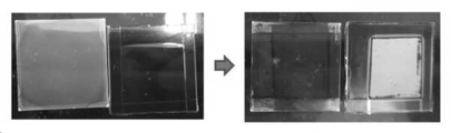
도4는 비교예의 잉크 조성물을 스핀 코팅 후 발광소재가 열전사 된 이미지다.
도5는 실시예의 잉크 조성물을 스핀 코팅 후 발광소재가 열전사 된 이미지다. 1 is a view schematically showing a pattern forming method by inkjet printing using the ink composition of the present invention.
2 is a light emitting image of a fine pattern embedded in the partition wall by an inkjet printing process.
FIG. 3 is a scanned image analyzed by AFM of the surface of the printed micropattern and height measurement data of the coated film surface.
4 is an image in which the light emitting material is thermally transferred after spin coating the ink composition of the comparative example.
5 is an image in which the light emitting material is thermally transferred after spin coating the ink composition of the embodiment.
이하에서는 첨부한 도면을 참조하여 본 발명을 설명하기로 한다. 그러나 본 발명은 여러 가지 상이한 형태로 구현될 수 있으며, 따라서 여기에서 설명하는 실시예로 한정되는 것은 아니다. 그리고 도면에서 본 발명을 명확하게 설명하기 위해서 설명과 관계없는 부분은 생략하였으며, 명세서 전체를 통하여 유사한 부분에 대해서는 유사한 도면 부호를 붙였다.Hereinafter, the present invention will be described with reference to the accompanying drawings. However, the present invention may be implemented in various different forms, and thus is not limited to the embodiments described herein. In addition, in order to clearly describe the present invention in the drawings, parts irrelevant to the description are omitted, and like reference numerals are assigned to similar parts throughout the specification.
명세서 전체에서, 어떤 부분이 다른 부분과 "연결(접속, 접촉, 결합)"되어 있다고 할 때, 이는 "직접적으로 연결"되어 있는 경우뿐 아니라, 그 중간에 다른 부재를 사이에 두고 "간접적으로 연결"되어 있는 경우도 포함한다. 또한 어떤 부분이 어떤 구성요소를 "포함"한다고 할 때, 이는 특별히 반대되는 기재가 없는 한 다른 구성요소를 제외하는 것이 아니라 다른 구성요소를 더 구비할 수 있다는 것을 의미한다.Throughout the specification, when a part is "connected (connected, contacted, coupled)" with another part, it is not only "directly connected" but also "indirectly connected" with another member in between. "It also includes the case where it is. Also, when a part “includes” a certain component, this means that other components may be further provided instead of excluding other components, unless otherwise stated.
본 명세서에서 사용한 용어는 단지 특정한 실시예를 설명하기 위해 사용된 것으로, 본 발명을 한정하려는 의도가 아니다. 단수의 표현은 문맥상 명백하게 다르게 뜻하지 않는 한, 복수의 표현을 포함한다. 본 명세서에서, "포함하다" 또는 "가지다" 등의 용어는 명세서상에 기재된 특징, 숫자, 단계, 동작, 구성요소, 부품 또는 이들을 조합한 것이 존재함을 지정하려는 것이지, 하나 또는 그 이상의 다른 특징들이나 숫자, 단계, 동작, 구성요소, 부품 또는 이들을 조합한 것들의 존재 또는 부가 가능성을 미리 배제하지 않는 것으로 이해되어야 한다.The terms used herein are only used to describe specific embodiments, and are not intended to limit the present invention. Singular expressions include plural expressions unless the context clearly indicates otherwise. In this specification, terms such as “include” or “have” are intended to indicate that a feature, number, step, operation, component, part, or combination thereof described in the specification exists, and that one or more other features are present. It should be understood that the existence or addition possibilities of fields or numbers, steps, operations, components, parts or combinations thereof are not excluded in advance.
이하 첨부된 도면을 참고하여 본 발명의 실시예를 상세히 설명하기로 한다.Hereinafter, embodiments of the present invention will be described in detail with reference to the accompanying drawings.
본 발명의 잉크젯 프린팅용 잉크 조성물에 따르면 상기 잉크 조성물은 발광 재료, 비승화형 고분자 유기화합물, 용매를 포함한다. 본 발명의 유기 발광 소자용 잉크 조성물은 발광 재료를 포함하므로 유기 발광 소자의 발광층 형성 등에 사용될 수 있다.According to the ink composition for inkjet printing of the present invention, the ink composition includes a luminescent material, a non-sublimable polymer organic compound, and a solvent. Since the ink composition for an organic light-emitting device of the present invention contains a light-emitting material, it can be used for forming a light-emitting layer of an organic light-emitting device.
상기 발광 재료는 발광층에 있어서 정공 및 전자를 이용하여 행하는 발광에 직접 또는 간접으로 기여하는 기능을 갖는다. 또, 본 명세서에 있어서 「발광」에는 형광에 의한 발광, 인광에 의한 발광 및 지연형광법에 의한 발광을 포함하는 것으로 한다. The light emitting material has a function of directly or indirectly contributing to light emission using holes and electrons in the light emitting layer. In addition, in this specification, "luminescence" shall include light emission by fluorescence, light emission by phosphorescence, and light emission by delayed fluorescence method.
화합물 내에서 전자의 여기상태는 단일항과 삼중항 상태가 있는데, 단일항 상태의 확률은 1/4이며 삼중항 상태의 확률은 3/4이다. 단일항 상태에서 바닥상태로 떨어지는 것이 형광이며 삼중항 상태에서 바닥상태로 떨어지는 것을 인광이라고 한다.There are single and triplet states of excitation of electrons in a compound. The probability of a singlet state is 1/4 and the probability of a triplet state is 3/4. Falling from the singlet state to the ground state is fluorescence, and falling from the triplet state to the ground state is called phosphorescence.
형광재료는 단일항 여기상태에서 유래되며 인광재료는 삼중항 여기자에서 유래되고 지연형광법은 최근 아다치 그룹을 중심으로 연구되고 있으며 삼중항 경유로 형광이 일어나도록 한다. 발광색에 따라서는 청색, 녹색 및 적색 발광재료와 보다 나은 천연색 구현을 위해 필요한 노란색 및 주황색 발광재료로 구분할 수 있다. 이러한 색상은 발광재료의 밴드갭에 의해 결정되며, 일반적으로 발광재료는 빛의 삼원색인 적색, 녹색 및 청색만으로 목적하는 모든 색을 표현 할 수 있으나 완벽한 색상 구현을 위해서는 노란색과 주황색도 함께 사용된다.The fluorescent material is derived from the singlet excitation state, the phosphorescent material is derived from the triplet exciton, and the delayed fluorescence method has recently been studied around the Adachi group and allows fluorescence to occur through the triplet. Depending on the emission color, it can be divided into blue, green, and red emission materials and yellow and orange emission materials necessary for better natural color realization. These colors are determined by the band gap of the luminescent material. In general, luminescent materials can express all the desired colors with only the three primary colors of light, red, green, and blue, but yellow and orange are also used for perfect color.
본 발명의 발광재료의 발광색은 예를 들어 청색, 녹색 및 적색일 수 있으며 보다 나은 색 구현을 위하여 노란색과 주황색일 수 있다. 발광재료의 발광색과 순도는 발광재료의 밴드갭에 의해 결정되는데 예를 들어, 밴드 갭은 일반적으로 2.0 eV에서 4.0 eV의 밴드 갭을 갖고 있는 재료를 의미한다. 이 때 2.75eV 주변은 빛의 파장으로 450 nm에 해당되며 청색을 뜻하고 2.4 eV 주변은 510 nm의 빛의 파장으로 녹색을 뜻하며2.0 eV 주변은 620 nm의 빛의 파장으로 적색을 뜻할 수 있다. The emission color of the light-emitting material of the present invention may be blue, green, and red, for example, and may be yellow and orange for better color realization. The emission color and purity of the light emitting material are determined by the band gap of the light emitting material. For example, the band gap generally refers to a material having a band gap of 2.0 eV to 4.0 eV. At this time, around 2.75 eV corresponds to 450 nm as the wavelength of light, blue refers to blue, 2.4 eV refers to green at 510 nm, and 2.0 eV refers to red at 620 nm.
본 발명의 녹색 형광 발광재료는 구체적으로 녹색 발광재료인 Alq3일 수 있고, Alq3를 호스트로 사용하는 C-545T (10-(2-벤조티아졸릴)-1,1,7,7-테트라메틸-2,3,6,7-테트라하이드로-1H,5H,11H-[l]벤조-피라노[6,7,8-ij]퀴놀리진-11-one)와 그 유도체들 및 퀴나크리돈 유도체들이 될 수도 있다. 본 발명의 적색 발광재료는 구체적으로 코닥사의 DCJTB일 수 있으며, 3-(다이시아노메틸렌)-5,5-다이메틸-1-[(4-다이메틸아미노)스타이릴]사이클로헥센(DCDDC), 6-메틸-3-{3-(1,1,6,6-테트라메틸-10-옥소-2,3,5,6-테트라하이드로-1H,4H,10H-11-옥사-3a-아자벤조[디]-9-안트라세닐)아크릴로일}파이란-2,4-다이온(AAAP) 등의 공지된 물질 일 수 있다. 본 발명의 청색 발광재료는 4,4-비스(2,2-다이페닐에텐-1-yl)바이페닐(DPVBi), Modified-DPVBi, 플루오렌 유도체, 피레네 유도체, 안트라센 유도체 및 spirobifluorene 유도체 등일 수 있다.The green fluorescent light emitting material of the present invention may specifically be Alq3, which is a green light emitting material, and C-545T (10- (2-benzothiazolyl) -1,1,7,7-tetramethyl- using Alq3 as a host. 2,3,6,7-tetrahydro-1H, 5H, 11H- [l] benzo-pyrano [6,7,8-ij] quinolizine-11-one) and its derivatives and quinacridone derivatives It can be. The red light emitting material of the present invention may be specifically DCJTB of Kodak Corporation, 3- (dicyanomethylene) -5,5-dimethyl-1-[(4-dimethylamino) styryl] cyclohexene (DCDDC) , 6-methyl-3- {3- (1,1,6,6-tetramethyl-10-oxo-2,3,5,6-tetrahydro-1H, 4H, 10H-11-oxa-3a-aza Benzo [di] -9-anthracenyl) acryloyl} pyran-2,4-dione (AAAP). The blue light emitting material of the present invention may be 4,4-bis (2,2-diphenylethene-1-yl) biphenyl (DPVBi), Modified-DPVBi, fluorene derivative, pyrene derivative, anthracene derivative, spirobifluorene derivative, etc. have.
형광을 이용한 발광재료의 내부양자 효율 한계치는 25%정도이고 인광을 이용한 발광소자의 내부양자효율 한계치는 75% 정도이다. 따라서 인광재료는 발광효율이 개선된 발광재료로 각광받고 있다. 단일항 또는 삼중항 여기상태에서 삼중항 여기상태로 에너지 전이가 잘 일어나야 하므로 그러한 특성을 나타내기 위해 전이금속이 중심원자로 있는 유기화합물이 바람직하다. 현재까지 공지된 재료로는 이리듐 (Ir), 백금 (Pt), 유로피움 (Eu), 터비움 (Tb)계 화합물 있으나 PT, Eu, Tb은 발광 효율이 높지 않아 대부분 Ir계 화합물들이 사용되고 있다. Ir 계 화합물은 페닐 피리딘 리간드로 구성된 화합물들로 공액의 길이 변화, 전자공여기, 혹은 전자 당김기의 도입에 의해 색을 조절 할 수 있다. 일반적으로 공액의 길이를 길게 하는 경우 적색을 보이고, 전자 공여기를 피리딘에 도입하거나 전자 당김기를 페닐에 도입하는 경우 청색을 나타낼 수 있다. 보조 리간드의 조절에 의해서도 색을 변화시킬 수 있으나 동종 리간드성 화합물에 비하여 안정성이 낮다는 단점이 있다.The limit of internal quantum efficiency of luminescent materials using fluorescence is about 25%, and the limit of internal quantum efficiency of luminescent devices using phosphorescence is about 75%. Therefore, the phosphorescent material has been spotlighted as a light-emitting material with improved luminous efficiency. Since the energy transfer must occur well from a singlet or triplet excited state to a triplet excited state, an organic compound having a transition metal as a central atom is preferable to exhibit such properties. Materials known to date include iridium (Ir), platinum (Pt), europium (Eu), and terbium (Tb) -based compounds, but most of the Ir-based compounds are used because PT, Eu, and Tb do not have high luminous efficiency. Ir-based compounds are compounds composed of phenyl pyridine ligands, and the color can be controlled by changing the length of the conjugate, introducing electron donors, or electron withdrawing groups. In general, when the length of the conjugate is elongated, it may appear red, and when an electron donor is introduced into pyridine or an electron withdrawing group may be introduced into phenyl, blue may be exhibited. The color can also be changed by adjusting the auxiliary ligand, but it has a disadvantage that stability is lower than that of the homologous ligand compound.
일 실시 형태에 있어서 발광 재료는 호스트 재료 및 도펀트 재료를 포함한다. 발광재료로 한 물질만 이용하는 경우에는 색순도와 발광효율이 떨어지는 문제가 있어 호스트의 발광스펙트럼과 도펀트의 흡수스펙트럼이 일치하는 호스트/도펀트 계를 이용하여 도펀트 단독으로 사용시에 비하여 색순도와 발광효율을 개선할 수 있으므로 바람직하다. 호스트/도펀트 시스템은 호스트 내에 분포되어있는 발광물질과 도펀트간의 상호작용을 최소화하여 소광현상과 같은 에너지 손실을 줄이고 호스트에서 도펀트로 에너지 전이를 통해 발광효율을 증가시키기 위한 것이다. 그 작용과정을 살펴보면 먼저 정공과 전자가 호스트를 여기시키고 여기에서 발광되는 에너지를 도펀트가 흡수한 뒤 다시 빛을 방출하는 과정으로 진행된다. 이상적인 호스트/도펀트계는 호스트의 발광스펙트럼과 도펀트의 흡수스펙트럼이 일치해 상술한 호스트에서 도펀트로의 에너지 전이가 잘 일어날 수 있어야 한다. 다만 일반적으로는 약 1/3이상의 겹침만 있어도 에너지 전이가 충분히 일어 날 수 있는 것으로 알려져 있다. 인광재료는 삼중항-삼중항 소멸 현상에 의해서 효율이 감소된다는 단점이 있으나, 호스트 물질에 도핑을 하여 이를 개선할 수 있다. 삼중항에 있던 엑시톤이 다시 호스트로 전이되는 호스트로의 역전하 이동을 막기 위해서는 호스트 물질의 단일항과 삼중항의 에너지 레벨이 도펀트 물질보다 높아야 한다. 또한 높은 열적 안정성 및 디바이스 내에서 전하 이동도가 일정 수준으로 유지되어야 한다. 현재 많은 종류의 호스트 물질이 개발되고 있으나, 카르바졸 유도체로 된 호스트물질이 블루 인광 호스트로서 가장 뛰어난 성능을 보이고 있다.In one embodiment, the luminescent material includes a host material and a dopant material. When using only one material as a luminescent material, there is a problem of poor color purity and luminous efficiency. Therefore, using a host / dopant system that matches the absorption spectrum of the host and the dopant of the host, color purity and luminous efficiency can be improved compared to when used alone. It is preferred because it can. The host / dopant system is intended to increase the luminous efficiency through energy transfer from the host to the dopant and to reduce energy loss such as quenching by minimizing the interaction between the dopant and the light emitting material distributed in the host. Looking at the working process, first, holes and electrons excite the host, and the dopant absorbs the energy emitted therefrom and then emits light again. In an ideal host / dopant system, the emission spectrum of the host and the absorption spectrum of the dopant must coincide, so that energy transfer from the host to the dopant can occur well. However, in general, it is known that even if there is an overlap of about 1/3 or more, energy transfer can occur sufficiently. Phosphorescent materials have the disadvantage that efficiency is reduced by the triplet-triplet extinction phenomenon, but can be improved by doping the host material. The energy level of the singlet and triplet of the host material must be higher than that of the dopant material to prevent the reverse charge transfer to the host where the exciton in the triplet is transferred back to the host. In addition, high thermal stability and charge mobility within the device must be maintained at a constant level. Currently, many types of host materials have been developed, but the host materials of carbazole derivatives show the best performance as a blue phosphorescent host.
상기 호스트 재료는 통상 발광층에 주입된 정공 및 전자를 수송하는 기능을 갖는다. 호스트 재료는 고분자 호스트 재료 및 저분자 호스트 재료로 분류된다. 또, 본 명세서에 있어서, 「저분자」란 중량 평균 분자량(Mw)이 5,000 이하의 것을 의미한다. 한편, 본 명세서에 있어서, 「고분자」란, 중량 평균 분자량(Mw)이 5,000 초과의 것을 의미한다. 일 실시 형태로 고분자 호스트 재료는 폴리(9-비닐카르바졸)(PVK), 폴리(p-페닐렌 비닐렌)(PPV), 폴리(플루오렌)(PF) 및 이들의 모노머 단위체를 포함하는 공중합체 등이 될 수 있다. 저분자 호스트 재료는 4,4′디(N-카르바졸릴)-1,1′-비페닐(CBP), 1,3-비스(N-카르바졸릴)벤젠(mCP), 1,3,5-트리스(9-카르바졸릴)벤젠(TCP), 1,3,5-트리스[4-(N-카르바졸릴)페닐]벤젠(TCPB) 및 9-[4-(10-페닐-9-안트릴)페닐]-9H-카르바졸(CzPA) 등이 될 수 있다. 상술의 호스트 재료는 단독으로 사용할 수 있고 2종 이상을 조합하여 사용 할 수도 있다. 구체적으로는 4,4′디(N-카르바졸릴)-1,1′-비페닐(CBP)을 사용하는 것이 더욱 바람직하다.The host material usually has a function of transporting holes and electrons injected into the light emitting layer. Host materials are classified into high molecular weight host materials and low molecular weight host materials. In addition, in this specification, "low molecular weight" means that the weight average molecular weight (Mw) is 5,000 or less. In addition, in this specification, "polymer" means that the weight average molecular weight (Mw) exceeds 5,000. In one embodiment, the polymer host material is poly (9-vinylcarbazole) (PVK), poly (p-phenylene vinylene) (PPV), poly (fluorene) (PF), and an airborne monomer unit thereof. Can be coalescence. Low molecular host materials include 4,4'di (N-carbazolyl) -1,1'-biphenyl (CBP), 1,3-bis (N-carbazolyl) benzene (mCP), 1,3,5 -Tris (9-carbazolyl) benzene (TCP), 1,3,5-tris [4- (N-carbazolyl) phenyl] benzene (TCPB) and 9- [4- (10-phenyl-9- Anthryl) phenyl] -9H-carbazole (CzPA) and the like. The above-described host materials can be used alone or in combination of two or more. Specifically, it is more preferable to use 4,4 'di (N-carbazolyl) -1,1'-biphenyl (CBP).
상기 도펀트 재료는, 수송된 정공 및 전자를 재결합함에 의해 얻어지는 에너지를 이용하여 발광하는 기능을 갖는다. 고분자 도펀트 재료로서는 폴리플루오렌(PFO), 폴리페닐렌비닐렌(PPV), 시아노폴리페닐렌비닐렌(CN-PPV), 폴리(4-비닐피리딘), 폴리(플루오레닐렌에티닐렌)(PFE) 및 이들의 모노머 단위체를 포함하는 공중합체 등이 될 수 있다. 저분자 도펀트 재료로서는 형광 발광 재료, 인광 발광 재료 등을 들 수 있다. 상기 형광 발광 재료로서는, 나프탈렌, 페릴렌, 피렌, 크리센, 안트라센, 쿠마린, 벤조피란, 로다민, 벤조티오잔텐, 아자벤조티오잔텐 및 이들의 유도체가 될 수 있다. 상기 인광 발광 재료로서는, 루테늄, 팔라듐, 오스뮴, 레늄, 이리듐, 백금 등이 중심원자로 있는 유기금속화합물을 들 수 있으며 단일항 또는 삼중항 여기상태에서 삼중항 여기 상태로의 계간 전이 또는 에너지 전이가 잘 일어날 수 있어 바람직하다. 구체적으로는 트리스[2-(p-톨릴)피리딘]루테늄, 트리스(2-페닐피리딘)루테늄, 트리스 (2-페닐피리딘)팔라듐, 트리스[2-(p-톨릴)피리딘]팔라듐, 트리스(2-페닐피리딘)오스뮴, 트리스[2-(p-톨릴)피리딘]오스뮴, 트리스[2-(p-톨릴)피리딘]레늄, 트리스(2-페닐피리딘)레늄, 트리스(2-페닐피리딘)이리듐(Ir(ppy)3), 트리스[2-(p-톨릴)피리딘]이리듐(Ir(mppy)3), 비스(2-페닐피리딘)백금, 트리스[2-(p-톨릴)피리딘]백금 등을 들 수 있다. 상술한 도펀트 재료 중, 도펀트 재료는 저분자 도펀트 재료인 것이 바람직하고 인광 발광 재료인 것이 보다 바람직하다. 예를 들어, 녹색 인광 발광재료로 트리스(2-페닐피리딘)이리듐(Ir(ppy)3)을 포함할 수 있고 적색 인광 발광재료 퀴놀린, 이소퀴놀린 등을 포함할 수 있다. 청색 인광 발광재료로는 톰슨 그룹과 UDC 가 공동으로 개발한 FIrpic을 포함할 수 있다. 구체적으로는 발광재료는 트리스(2-페닐피리딘)이리듐(Ir(ppy)3)인 것이 더욱 바람직하다. 상술의 도펀트 재료는, 단독으로 사용하거나 2종 이상을 조합하여 사용할 수 있다.The dopant material has a function of emitting light using energy obtained by recombining transported holes and electrons. As a polymer dopant material, polyfluorene (PFO), polyphenylenevinylene (PPV), cyanopolyphenylenevinylene (CN-PPV), poly (4-vinylpyridine), poly (fluorenyleneethynylene) (PFE) and copolymers containing these monomer units. Fluorescent light emitting materials, phosphorescent light emitting materials, etc. are mentioned as a low molecular dopant material. As the fluorescent material, naphthalene, perylene, pyrene, chrysene, anthracene, coumarin, benzopyran, rhodamine, benzothioxanthene, azabenzothioxanthene, and derivatives thereof may be used. Examples of the phosphorescent material include organometallic compounds having ruthenium, palladium, osmium, rhenium, iridium, platinum, and the like as a central atom, and the transition between singlet or triplet excited state to triplet excited state or energy transfer is good. It is desirable because it can happen. Specifically, tris [2- (p-tolyl) pyridine] ruthenium, tris (2-phenylpyridine) ruthenium, tris (2-phenylpyridine) palladium, tris [2- (p-tolyl) pyridine] palladium, tris (2 -Phenylpyridine) osmium, tris [2- (p-tolyl) pyridine] osmium, tris [2- (p-tolyl) pyridine] rhenium, tris (2-phenylpyridine) rhenium, tris (2-phenylpyridine) iridium ( Ir (ppy) 3), tris [2- (p-tolyl) pyridine] iridium (Ir (mppy) 3), bis (2-phenylpyridine) platinum, tris [2- (p-tolyl) pyridine] platinum, etc. Can be lifted. Among the above-mentioned dopant materials, the dopant material is preferably a low-molecular dopant material and more preferably a phosphorescent material. For example, tris (2-phenylpyridine) iridium (Ir (ppy) 3) may be included as the green phosphorescent material, and red phosphorescent material quinoline, isoquinoline, or the like. The blue phosphorescent material may include FIrpic jointly developed by the Thomson Group and UDC. More specifically, the light emitting material is more preferably tris (2-phenylpyridine) iridium (Ir (ppy) 3). The above-mentioned dopant material can be used individually or in combination of 2 or more types.
상기 비승화형 고분자 유기화합물은 단분자 물질로만 이루어진 잉크조성물에서 발생하는 결정화와 커피링현상을 방지하는 기능을 한다. 비승화형 고분자 유기화합물은 공정 중 승화되지 않아 잉크 조성물의 농도 및 점도를 균일하게 유지 할 수 있으므로 바람직하다. 또한 후속공정인 광열전사 공정에서 발광재료만을 선택적으로 전사할 수 있어 바람직하다.The non-sublimable polymer organic compound serves to prevent crystallization and coffee ring phenomena occurring in the ink composition composed of only a single molecule material. Non-sublimable polymer organic compounds are preferred because they do not sublime during the process and can maintain the concentration and viscosity of the ink composition uniformly. In addition, it is preferable because only the light-emitting material can be selectively transferred in a subsequent photothermal transfer process.
상기 비승화형 고분자 유기화합물의 함유량은, 잉크 고형분100중량%에 대하여, 0.1 내지 20중량%인 것이 바람직하고, 0.1 내지 10중량% 인 것이 보다 바람직하다. 상기 잉크 고형분은 발광재료 및 비승화형 고분자 유기화합물의 혼합물을 의미한다. 비승화형 고분자 유기화합물의 함유량이 0.1중량% 미만이면, 잉크조성물의 결정화 및 커피링현상을 방지 할 수 없다. 한편, 비승화형 고분자의 함유량이 20중량% 초과이면 잉크조성물의 점도가 크게 상승하여 공정편의성이 저하된다.The content of the non-sublimable polymer organic compound is preferably 0.1 to 20% by weight, and more preferably 0.1 to 10% by weight with respect to 100% by weight of the ink solid content. The ink solid content means a mixture of a luminescent material and a non-sublimable polymer organic compound. If the content of the non-sublimable polymer organic compound is less than 0.1% by weight, crystallization and coffee ring phenomenon of the ink composition cannot be prevented. On the other hand, if the content of the non-sublimable polymer is more than 20% by weight, the viscosity of the ink composition is greatly increased, and process convenience is lowered.
상기 비승화형 고분자 유기화합물은 바이닐계 고분자일 수 있고, 바람직하게는 아크릴계 고분자 유기화합물일 수 있다. 상술한 비승화형 고분자는 폴리메틸메타크릴레이트(PMMA), 폴리메틸아크릴레이트(PMA), 폴리부틸메타크릴레이트(PBuMA), 폴리터트부틸메타크릴레이트(PtBM), 폴리터트부틸아크릴레이트(PtBA), 폴리하이드록시에틸메타크릴레이트(PHEMA) 및 이들의 모노머 단위체를 포함하는 공중합체 등이 될 수 있다. 비승화형 고분자 유기화합물의 구체적인 예로 폴리메틸메타크릴레이트(PMMA) 일 수 있다.The non-sublimable polymer organic compound may be a vinyl polymer, preferably an acrylic polymer organic compound. The above-mentioned non-sublimable polymers include polymethyl methacrylate (PMMA), polymethyl acrylate (PMA), polybutyl methacrylate (PBuMA), polytertbutyl methacrylate (PtBM), and polytertbutyl acrylate (PtBA). , Polyhydroxyethyl methacrylate (PHEMA) and copolymers containing these monomer units. A specific example of the non-sublimable polymer organic compound may be polymethyl methacrylate (PMMA).
상기 비승화형 고분자 유기화합물의 중량 평균 분자량(Mw)은, 5,000 초과 5,000,000 이하인 것이 바람직하고, 5,000 초과1,000,000 이하인 것이 보다 바람직하다.The weight-average molecular weight (Mw) of the non-sublimable polymer organic compound is preferably 5,000 to 5,000,000 or less, more preferably 5,000 to 1,000,000 or less.
상기 용매는 공지의 것이 사용될 수 있으며 방향족계 용매, 알칸계 용매, 에테르계 용매, 알코올계 용매, 에스테르계 용매, 아미드계 용매, 다른 용매 등이 사용될 수 있다. 구체적으로는 수산화암모늄, 이소프로필알코올, 클로로벤젠, 다이클로로벤젠, 톨루엔, 클로로포름, 헥산, N-메틸 피롤리돈, 에탄올 아민, 에탄올 및 메탄올로 이루어지는 군으로부터 선택되는 1종 또는 2종 이상의 혼합물 일 수 있다.As the solvent, a known one can be used, and an aromatic solvent, an alkane solvent, an ether solvent, an alcohol solvent, an ester solvent, an amide solvent, and other solvents can be used. Specifically, one or two or more mixtures selected from the group consisting of ammonium hydroxide, isopropyl alcohol, chlorobenzene, dichlorobenzene, toluene, chloroform, hexane, N-methyl pyrrolidone, ethanol amine, ethanol and methanol Can be.
본 발명의 잉크 조성물에는 상기 용매가 전체 잉크조성물 100중량% 기준 80 ~ 99.9 중량%, 바람직하게는 95 ~ 99 중량% 범위로 포함될 수 있다. 상기 용매의 함량이 80 중량% 미만이면 잉크 조성물의 점도가 높아 공정성이 떨어지는 문제가 발생 할 수 있고, 99.9 중량%를 초과하면 점도가 낮아 공정성이 떨어지고 잉크 고형분이 분리되는 문제가 있을 수 있다. In the ink composition of the present invention, the solvent may be included in a range of 80 to 99.9 wt%, preferably 95 to 99 wt%, based on 100 wt% of the total ink composition. If the content of the solvent is less than 80% by weight, the viscosity of the ink composition may be high, resulting in poor processability, and if it exceeds 99.9% by weight, viscosity may be low, resulting in poor processability and separation of ink solids.
상기 잉크 조성물의 점도는 1~50mPas인 것이 바람직하고, 1~20mPa·s인 것이 더욱 바람직하다. 잉크 조성물의 점도가 1mPa·s 이상이면, 도막 건조 시에 물결의 발생을 호적하게 방지할 수 있으므로 바람직하다. 또한, 유기 발광 소자용 잉크 조성물의 점도가 20mPa·s 이하이면, 도포가 용이하여 공정 적합성이 있어 바람직하다. The viscosity of the ink composition is preferably 1 to 50 mPas, and more preferably 1 to 20 mPa · s. When the viscosity of the ink composition is 1 mPa · s or more, it is preferable since it is possible to suitably prevent the occurrence of a wave when drying the coating film. In addition, when the viscosity of the ink composition for an organic light emitting device is 20 mPa · s or less, it is easy to apply and is preferable because it has process suitability.
본 명세서에 있어서, 「점도」의 값은, 회전식 점도계에 의해 측정된 값을 채용하는 것으로 한다.In this specification, the value of "viscosity" is assumed to be a value measured by a rotary viscometer.
본 발명의 잉크젯 조성물에 있어서는 발광재료, 비승화형 고분자, 용매 이외에 필요에 따라 각종 계면활성제를 첨가할 수 있다. 상기 계면활성제는 예를 들어 음이온계 계면활성제, 양이온계 계면활성제, 비이온계 계면활성제를 사용할 수 있다. 또한 저분자형이나 고분자형의 불소계 또는 실리콘계의 계면활성제를 사용할 수 있다. 본 발명에 따른 조성물은 추가적으로, 표면 활성화합물, 윤활제, 습윤제, 분산제, 소수성화제, 접착제, 흐름 증진제, 소포제, 반응성 또는 비반응성일 수 있는 희석제, 탈기제, 보조제, 착색제, 염료, 증감제, 안정화제 등과 같은 하나 이상의 추가의 성분들을 포함할 수 있다.In the inkjet composition of the present invention, various surfactants may be added as needed in addition to the light emitting material, the non-sublimable polymer, and the solvent. The surfactant may be, for example, an anionic surfactant, a cationic surfactant, or a nonionic surfactant. In addition, a low molecular weight or high molecular weight fluorine-based or silicone-based surfactant can be used. The composition according to the invention is additionally, surface active compounds, lubricants, wetting agents, dispersing agents, hydrophobicizing agents, adhesives, flow enhancers, antifoaming agents, diluents, degassing agents, auxiliary agents, coloring agents, dyes, sensitizers, stable It may include one or more additional ingredients, such as a topic.
본 발명의 잉크젯 프린팅에 의한 패턴 형성방법은 상술한 잉크 조성믈을 배합하는 단계(S100), 상기 배합된 잉크조성물을 기판 표면에 잉크젯 프린팅하는 단계(S200) 및 상기 기판 표면에 프린팅된 잉크조성물을 타겟 기판에 광열전사하는 단계(S300)를 포함할 수 있다. The method of forming a pattern by inkjet printing of the present invention comprises the steps of blending the ink composition described above (S100), inkjet printing the blended ink composition on the substrate surface (S200), and the ink composition printed on the substrate surface. It may include the step (S300) of photo-thermal transfer to the target substrate.
상기 잉크 조성물을 배합하는 단계(S100)는 용매를 포함하는 용액 또는 분산액 형태로 제조하는 방법, 상기 용액 또는 분산액에 발광 재료를 첨가하고 이어서 비승화형 고분자 유기화합물을 첨가하는 방법, 발광 재료 및 용매를 포함하는 용액 또는 분산액을 제조하고, 이어서 당해 용액 또는 분산액에 비승화형 고분자 유기화합물을 첨가하는 방법, 용매를 포함하는 용액 또는 분산액과 발광 재료 및 용매를 포함하는 용액 또는 분산액 및 비승화형 고분자 유기화합물을 포함하는 용액 또는 분산액을 각각 제조하고, 이들 용액 또는 분산액을 혼합하는 방법 등을 포함 할 수 있다. 또한, 잉크조성물 배합을 위하여 사용하는 원료인 발광 재료, 비승화형 고분자 유기화합물, 및 용매 등은 불순물이나 이온 성분을 함유하지 않는 고순도품을 사용하는 것이 노즐 눈막힘을 방지할 수 있고 각 물질에서 요구되는 기능을 충분히 수행할 수 있어 바람직하다. 상술한 방법으로 얻어진 잉크조성물은 연속 잉크젯 프린팅 및 드랍-온-디맨드 등 공지 관용의 잉크젯 기록 방식의 프린터에 이용될 수 있다.The step (S100) of blending the ink composition is a method of preparing a solution or dispersion containing a solvent, adding a luminescent material to the solution or dispersion, and then adding a non-sublimable polymer organic compound, a luminescent material and a solvent. Method for preparing a solution or dispersion comprising a solution, and then adding a non-sublimable polymer organic compound to the solution or dispersion, a solution or dispersion containing a solvent and a solution or dispersion containing a luminescent material and a solvent and a non-sublimable polymer organic compound It may include a method of preparing a solution or dispersion containing each, and mixing these solutions or dispersion. In addition, the use of high-purity products that do not contain impurities or ionic components, such as luminescent materials, non-sublimable polymer organic compounds, and solvents, which are raw materials used for mixing the ink composition, can prevent nozzle clogging and are required by each material. It is preferable because it can perform a sufficient function. The ink composition obtained by the above-described method can be used in a conventional inkjet recording type printer such as continuous inkjet printing and drop-on-demand.
상기 배합된 잉크 조성물을 기판 표면에 잉크젯 프린팅하는 단계(S200)는 연속 잉크젯 프린팅 및 드랍-온-디맨드 잉크젯 프린팅 방식으로 진행 될 수 있다. 구체적인 예를 들어 피에조 방식, 서머버블방식 및 버블젯 분사방식 등이 이용 될 수 있다. 전자 재료 프린팅에는 Drop-on-Demand 방식만이 이용되고 있는데, Drop-on-Demand 방식은 더 적은 재료로 동일 면적 프린팅이 가능하다는 장점이 있다.. 서머버블방식은 분사노즐을 가열하여 생긴 수증기압으로 잉크를 분출하며 분사노즐에 열 전도체인 저항제가 결합되어 입력신호에 따라 전류가 저항체의 온도를 상승시키면 잉크가 순간적으로 끓어올라 잉크방울이 튀어나가게 되는 원리를 이용하며 버블젯 분사방식은 입력된 신호에 따라 노즐 속의 잉크를 밀어낼 대 공기방울을 이용하는 것으로 잉크실이 따로 있지 않아 노즐 막힘이 적다.The step (S200) of inkjet printing the blended ink composition onto the substrate surface may be performed by continuous inkjet printing and drop-on-demand inkjet printing. For a specific example, a piezo method, a thermo bubble method, and a bubble jet injection method may be used. Only the drop-on-demand method is used for printing electronic materials, and the drop-on-demand method has the advantage of being able to print the same area with less material. The thermo-bubble method is the vapor pressure generated by heating the spray nozzle. The ink jet is ejected and a resistor, which is a heat conductor, is combined with the spray nozzle, and when the current rises the temperature of the resistor according to the input signal, the ink boils up instantaneously and the ink droplets splash out. Therefore, when pushing out the ink in the nozzle, air bubbles are used.
상술한 배합된 잉크조성물을 기판 표면에 잉크젯 프린팅하는 단계에서 사용되는 잉크젯 프린터로는 드랍-온-디맨드 방식의 프린팅 헤드가 사용되는 것이 바람직하며, 예를 들어 캐논(Cannon), 휴렛-패커드(Hewlett-Packard) 등에서 판매되는 일반 잉크젯 프린터에서 다이마틱스(Dimatix)와 같은 산업용 잉크젯 프린터가 사용 될 수 있다.A drop-on-demand printing head is preferably used as the inkjet printer used in the step of inkjet printing the blended ink composition on the substrate surface, for example, Canon, Hewlett-Packard (Hewlett) -In general inkjet printers sold by Packard, etc., industrial inkjet printers such as Dimatix can be used.
상기 기판 표면에 프린팅된 잉크 조성물을 타겟 기판에 광열전사하는 단계(S300)는 잉크젯 프린팅된 기판과 타겟 기판을 맞대어 가압하는 단계, 프린팅된 기판에서 타겟 기판 방향으로 광열변환층에 광원을 조사하여 프린팅된 잉크조성물을 타겟기판으로 전사하는 단계를 포함 할 수 있다. 상기 광열변환층은 광열전환층은 특정 파장의 광을 흡수하고 입사광 중 적어도 일부를 열로 전환시키는 기능을 한다. 상기 광원은 레이저, IPL(Intense Pulse Light) 및 이들의 조합으로 이루어지는 군에서 선택 될 수 있다. In the step S300 of photothermal transfer of the ink composition printed on the substrate surface to the target substrate, the inkjet printed substrate and the target substrate are pressed against each other, and the light substrate is irradiated from the printed substrate to the target substrate to illuminate the photothermal conversion layer for printing. It may include the step of transferring the ink composition to the target substrate. The photothermal conversion layer functions to absorb light of a specific wavelength and convert at least a portion of incident light into heat. The light source may be selected from the group consisting of laser, IPL (Intense Pulse Light) and combinations thereof.
[제조예1][Production Example 1]
발광재료 및 용매를 포함하는 잉크젯 프린터용 잉크 조성물의 제조예.An example of manufacturing an ink composition for an inkjet printer comprising a luminescent material and a solvent.
교반기를 구비한 반응 용기에, 용매로 사용되는 Chlorobenzene (화학식 1의 (d))을 전체 잉크조성물 100wt% 기준 99wt%로 준비하고 인광 호스트로 CBP[4,4'-N,N'-dicarbazole-biphenyl](화학식1의 (a))을, 도판트로서는 Ir(ppy)3 [tris(2-phenylpyridine)-iridium](화학식1의 (b)) 을 첨가한다. 잉크 고형분 함량은CBP +Irmppy3 = 10mg 이며, 표1에 따라 잉크 고형분 함량을 기준으로 CBP는 90wt%, Ir(ppy)3는 10wt%이다.In a reaction vessel equipped with a stirrer, Chlorobenzene ((d) of Chemical Formula 1) used as a solvent was prepared at 99wt% based on 100wt% of the total ink composition, and used as a phosphorescent host CBP [4,4'-N, N'-dicarbazole- biphenyl] ((a) of formula 1) and Ir (ppy) 3 [tris (2-phenylpyridine) -iridium] ((b) of formula 1) as a dopant. The ink solids content is CBP + Irmppy3 = 10mg, CBP is 90wt% and Ir (ppy) 3 is 10wt% based on the ink solids content according to Table 1.
[제조예2][Production Example 2]
발광재료, 비승화형 고분자 유기화합물 및 용매를 포함하는 잉크젯 프린터용 잉크조성물의 제조예.An example of manufacturing an ink composition for an inkjet printer comprising a luminescent material, a non-sublimable polymer organic compound and a solvent.
교반기를 구비한 반응 용기에, 용매로 사용되는 Chlorobenzene(화학식1의 (d)) 을 전체 잉크조성물 100wt% 기준 99wt%로 준비하고 인광 호스트로 CBP[4,4'-N,N'-dicarbazole-biphenyl](화학식1의 (a))을, 도판트로서는 Ir(ppy)3 [tris(2-phenylpyridine)-iridium](화학식1의 (b))을 첨가한다. 이에 비승화형 고분자 유기 화합물로 PMMA (Poly(methyl methacrylate))(화학식1의 (c))을 첨가한다. 잉크 고형분 함량은CBP +Irmppy3 + PMMA = 10mg 이며, 표1에 따라 잉크 고형분 함량을 기준으로 CBP는 81wt%, Ir(ppy)3는 9wt%, PMMA는 10wt% 이다.In a reaction vessel equipped with a stirrer, Chlorobenzene ((d) of Chemical Formula 1) used as a solvent was prepared at 99 wt% based on 100 wt% of the total ink composition, and used as a phosphorescent host CBP [4,4'-N, N'-dicarbazole- biphenyl] ((a) of formula 1) and Ir (ppy) 3 [tris (2-phenylpyridine) -iridium] ((b) of formula 1) as a dopant. To this, PMMA (Poly (methyl methacrylate)) (Formula 1 (c)) is added as a non-sublimable polymer organic compound. The solid content of the ink is CBP + Irmppy3 + PMMA = 10mg, CBP is 81wt%, Ir (ppy) 3 is 9wt%, and PMMA is 10wt% based on the ink solids content according to Table 1.
[화학식1][Formula 1]

[실험예1][Experimental Example 1]
제조예1 및 제조예2의 잉크조성물을 이용해 잉크젯 프린팅된 미세패턴의 형광 이미지.Fluorescence image of the inkjet printed fine pattern using the ink composition of Preparation Example 1 and Preparation Example 2.
프린팅 노즐을 통해 상기 제조예1의 잉크조성물을 격벽 사이에 액적 형태로 분사시켜 미세 패턴을 형성한다. 형성된 미세 패턴에 빛을 조사 한 뒤 빛 루미네선스 이미지를 촬영하였다.The ink composition of Preparation Example 1 is sprayed in the form of droplets between the partition walls through a printing nozzle to form a fine pattern. After the light was irradiated to the formed fine pattern, a light luminescence image was taken.
도2는 격벽 내부에 잉크젯 프린팅 공정으로 함입된 미세 패턴의 형광 이미지로, 왼쪽은 제조예1의 잉크조성물을 이용해 잉크젯 프린팅된 미세패턴의 형광이미지이고 오른쪽은 제조예2의 잉크조성물을 이용해 잉크젯 프린팅된 미세패턴의 형광이미지이다.Figure 2 is a fluorescence image of the fine pattern embedded in the inkjet printing process inside the partition wall, the left is a fluorescence image of the fine pattern inkjet printed using the ink composition of Preparation Example 1, the right is inkjet printing using the ink composition of Preparation Example 2 It is a fluorescent image of a fine pattern.
커피링 현상(Coffee-ring)은 커피 한 방울이 책상에 떨어져 마르게 되면 액적 외곽에 선명한 선을 띠면서 반지모양(ring)으로 형성되는 현상을 말한다. . 코팅 과정에서 코팅액이 증발하면서 코팅액에 섞여 있는 미세 입자가 외곽 쪽으로만 몰리고 중심부에는 입자가 없게 되는 커피링 현상이 나타나 코팅 품질을 떨어뜨린다. The coffee-ring phenomenon is a phenomenon in which a drop of coffee is formed into a ring while having a clear line on the outside of a droplet when it dries on the desk and dries. . During the coating process, as the coating liquid evaporates, fine particles mixed with the coating liquid are concentrated only toward the outer side, and a coffee ring phenomenon in which there are no particles in the center appears, deteriorating the coating quality.
본 발명의 실험예1에 있어서, 도2를 참조하면, 미세패턴의 경우 비교예 대비 균일한 두께로 미세 패턴이 형성되었으며 격벽으로 입자가 몰리는 커피링 현상 또한 적은 것을 이미지상으로 확인 할 수 있다. 또한 비교예의 미세 패턴 프린팅 결과는 격벽층 외부로 넘쳐 흐른 데 반해 실시예의 경우 목적한 격벽층 내부에만 잉크가 함입된 것을 확인 할 수 있다.In Experimental Example 1 of the present invention, referring to FIG. 2, in the case of the micropattern, a micropattern was formed with a uniform thickness compared to the comparative example, and it can be confirmed from the image that the coffee ring phenomenon in which particles are driven into the partition wall is also small. In addition, while the fine pattern printing result of the comparative example overflowed to the outside of the barrier layer, in the case of the example, it can be confirmed that only the inside of the desired barrier rib layer contained ink.
[실험예2][Experimental Example 2]
제조예1 및 제조예2의 잉크조성물을 이용해 잉크젯 프린팅된 미세패턴의 AFM 측정 데이터.AFM measurement data of the inkjet printed fine pattern using the ink composition of Preparation Example 1 and Preparation Example 2.
프린팅 노즐을 통해 상기 제조예1의 잉크조성물을 격벽 사이에 액적 형태로 분사시켜 미세 패턴을 형성한다. 형성된 미세 패턴을 AFM [Atomic Force Microscope]을 이용하여 표면 스캔 이미지와 거칠기 데이터를 확보하였다.The ink composition of Preparation Example 1 is sprayed in the form of droplets between the partition walls through a printing nozzle to form a fine pattern. The formed fine pattern was obtained by using AFM [Atomic Force Microscope] to obtain surface scan images and roughness data.
프린팅 노즐을 통해 상기 제조예2의 잉크조성물을 격벽 사이에 액적 형태로 분사시켜 미세 패턴을 형성한다. 형성된 미세 패턴을 AFM [Atomic Force Microscope]을 이용하여 표면 스캔 이미지와 거칠기 데이터를 확보하였다.A fine pattern is formed by spraying the ink composition of Preparation Example 2 in the form of droplets between partition walls through a printing nozzle. The formed fine pattern was obtained by using AFM [Atomic Force Microscope] to obtain surface scan images and roughness data.
도3은 프린팅된 미세 패턴의 표면을 AFM으로 분석한 스캔 결과 및 코팅막 표면의 높낮이 측정 결과로 왼쪽은 제조예1의 잉크조성물을 이용해 잉크젯 프린팅된 미세패턴의 스캔 이미지 및 데이터이고 오른쪽은 제조예2의 잉크조성물을 이용해 잉크젯 프린팅된 미세패턴의 스캔 이미지 및 데이터이다.3 is a scan result of analyzing the surface of the printed micropattern by AFM and the height measurement result of the surface of the coating film, the left is the scanned image and data of the inkjet printed micropattern using the ink composition of Preparation Example 1, and the right is Production Example 2 This is a scanned image and data of an inkjet printed micropattern using an ink composition of.
본 발명의 실험예2에 있어서, 도3을 참조하면, AFM분석에서는 단분자 발광물질만을 함유한 비교예의 경우 18nm의 표면 거칠기 값을 보이는데 반해, 고분자 첨가제가 함유된 실시예에서는 1.9nm의 거칠기 값으로, 비교예 대비 상당히 개선된 균일 박막 표면이 형성됨을 확인 할 수 있다.In Experimental Example 2 of the present invention, referring to Figure 3, AFM analysis shows a surface roughness value of 18 nm in the case of a comparative example containing only a single molecule luminescent material, whereas in the example containing a polymer additive, a roughness value of 1.9 nm As a result, it can be seen that a substantially improved uniform thin film surface is formed compared to the comparative example.
[실험예3] [Experimental Example 3]
제조예1 및 제조예2의 잉크조성물을 이용해 잉크젯 프린팅된 미세패턴의 열전사.Thermal transfer of inkjet printed micropatterns using the ink compositions of Preparation Example 1 and Preparation Example 2.
상기 제조예1의 잉크조성물을 유리기판 위에 스핀 코팅 후 온도 300 ℃/15분 조건에서 열전사 처리하여 타겟 기판으로 전사하였다.The ink composition of Preparation Example 1 was spin coated on a glass substrate and then transferred to a target substrate by thermal transfer treatment at a temperature of 300 ° C./15 minutes.
상기 제조예2의 잉크조성물을 유리기판 위에 스핀 코팅 후 온도 300 ℃/15분 조건에서 열전사 처리하여 타겟 기판으로 전사하였다.The ink composition of Preparation Example 2 was spin coated on a glass substrate and then transferred to a target substrate by thermal transfer treatment at a temperature of 300 ° C./15 minutes.
도4는 제조예1의 잉크 조성물을 스핀 코팅 후 발광소재가 타겟 기판으로 열전사 된 이미지다.4 is an image in which the light emitting material is thermally transferred to a target substrate after spin coating the ink composition of Preparation Example 1.
도5는 제조예1의 잉크 조성물을 스핀 코팅 후 발광소재가 타겟 기판으로 열전사 된 이미지다.5 is an image in which the light emitting material is thermally transferred to a target substrate after spin coating the ink composition of Preparation Example 1.
실험예3의 도4및 도5를 참조하면, 후속 열전사 공정 시험 결과 비교예 및 실시예의 발광소재 모두 열전사 공정을 통해서 타겟기판으로의 전사가 가능하여 열전사 공정을 통해 미세 화소 패턴 제작 및 초고해상도 디스플레이 제작이 가능함을 확인할 수 있다.Referring to FIGS. 4 and 5 of Experimental Example 3, the results of the subsequent thermal transfer process test, both the comparative example and the light emitting material of the example can be transferred to the target substrate through the thermal transfer process, thereby producing a fine pixel pattern through the thermal transfer process and It can be confirmed that it is possible to manufacture an ultra-high resolution display.
따라서, 본 발명은 잉크젯 프린팅용 잉크 조성물에 비승화형 고분자를 도입함으로써 잉크젯 프린팅된 미세패턴의 박막 균질도를 향상 시킬 수 있고, 후속공정으로 광열전사가 가능하므로 이를 통해서 미세 화소 및 초고해상도 디스플레이 제작이 가능하다.Therefore, the present invention can improve the thin film homogeneity of the inkjet printed fine pattern by introducing a non-sublimation type polymer into the ink composition for inkjet printing, and it is possible to produce micro-pixels and ultra-high resolution displays through this because photothermal transfer is possible in a subsequent process. It is possible.
전술한 본 발명의 설명은 예시를 위한 것이며, 본 발명이 속하는 기술분야의 통상의 지식을 가진 자는 본 발명의 기술적 사상이나 필수적인 특징을 변경하지 않고서 다른 구체적인 형태로 쉽게 변형이 가능하다는 것을 이해할 수 있을 것이다. 그러므로 이상에서 기술한 실시예들은 모든 면에서 예시적인 것이며 한정적이 아닌 것으로 이해해야만 한다. 예를 들어, 단일형으로 설명되어 있는 각 구성 요소는 분산되어 실시될 수도 있으며, 마찬가지로 분산된 것으로 설명되어 있는 구성 요소들도 결합된 형태로 실시될 수 있다.The above description of the present invention is for illustration only, and those skilled in the art to which the present invention pertains can understand that the present invention can be easily modified into other specific forms without changing the technical spirit or essential features of the present invention. will be. Therefore, it should be understood that the embodiments described above are illustrative in all respects and not restrictive. For example, each component described as a single type may be implemented in a distributed manner, and similarly, components described as distributed may be implemented in a combined form.
본 발명의 범위는 후술하는 특허청구범위에 의하여 나타내어지며, 특허청구범위의 의미 및 범위 그리고 그 균등 개념으로부터 도출되는 모든 변경 또는 변형된 형태가 본 발명의 범위에 포함되는 것으로 해석되어야 한다.The scope of the present invention is indicated by the following claims, and all changes or modifications derived from the meaning and scope of the claims and their equivalent concepts should be interpreted to be included in the scope of the present invention.
Claims (10)
상기 발광재료는 호스트 재료 및 도펀트 재료를 포함하는 것을 특징으로 하는 잉크젯 프린팅용 잉크 조성물.According to claim 1,
The luminescent material is an ink composition for inkjet printing, characterized in that it comprises a host material and a dopant material.
상기 비승화형 고분자 유기화합물은 잉크 고형분100 중량%에 대하여 0.1 내지 20 중량%인 것을 특징으로 하는 잉크젯 프린팅용 잉크 조성물.According to claim 1,
The non-sublimable polymer organic compound is an ink composition for inkjet printing, characterized in that 0.1 to 20% by weight based on 100% by weight of the ink solids.
상기 비승화형 고분자 유기화합물은 아크릴레이트계 고분자인 것을 특징으로 하는 잉크젯 프린팅용 잉크 조성물.According to claim 1,
The non-sublimable polymer organic compound is an acrylate-based polymer inkjet printing ink composition, characterized in that.
상기 비승화형 고분자 유기화합물은 폴리메틸메타크릴레이트, 폴리아크릴산, 폴리메틸아크릴레이트로 이루어진 군으로부터 선택되는 것을 특징으로 하는 잉크젯 프린팅용 잉크 조성물.According to claim 1,
The non-sublimable polymer organic compound is an ink composition for inkjet printing, characterized in that it is selected from the group consisting of polymethyl methacrylate, polyacrylic acid, and polymethyl acrylate.
상기 용매는 수산화암모늄, 이소프로필알코올, 클로로벤젠, 다이클로로벤젠, 톨루엔, 클로로포름, 헥산, N-메틸 피롤리돈, 에탄올 아민, 에탄올 및 메탄올로 이루어지는 군으로부터 선택되는 1종 또는 2종 이상의 혼합물인 것을 특징으로 하는 잉크젯 프린팅용 잉크 조성물.According to claim 1,
The solvent is one or a mixture of two or more selected from the group consisting of ammonium hydroxide, isopropyl alcohol, chlorobenzene, dichlorobenzene, toluene, chloroform, hexane, N-methyl pyrrolidone, ethanol amine, ethanol and methanol. Characterized in that the ink composition for inkjet printing.
상기 배합된 잉크 조성물을 기판 표면에 잉크젯 프린팅하는 단계;
상기 기판 표면에 프린팅된 잉크 조성물을 타겟 기판에 광열전사하는 단계;
를 포함하는 잉크젯 프린팅에 의한 패턴 형성방법.Compounding the ink composition according to claim 1;
Inkjet printing the blended ink composition onto a substrate surface;
Photothermal transfer of the ink composition printed on the substrate surface to a target substrate;
Pattern formation method by inkjet printing comprising a.
상기 잉크젯 프린팅은 연속 잉크젯(ink-jet) 프린팅; 및
드랍-온-디맨드(drop-on-demand) 잉크젯 프린팅;으로 이루어지는 군으로부터 선택되는 것을 특징으로 하는 잉크젯 프린팅에 의한 패턴 형성방법.The method of claim 7,
The inkjet printing may include continuous inkjet printing; And
Drop-on-demand (drop-on-demand) inkjet printing; pattern formation method by inkjet printing, characterized in that selected from the group consisting of.
상기 광열전사는,
상기 잉크젯 프린팅된 기판과 상기 타겟 기판을 맞대어 가압하는 단계; 및
상기 프린팅된 기판에서 상기 타겟 기판 방향으로 광열변환층에 광원을 조사하여 상기 프린팅된 잉크조성물을 상기 타겟 기판으로 전사하는 단계;를
포함하는 것을 특징으로 하는 잉크젯 프린팅에 의한 패턴 형성방법.The method of claim 7,
The photothermal transfer,
Pressing the inkjet printed substrate against the target substrate; And
Transferring the printed ink composition to the target substrate by irradiating a light source to the photothermal conversion layer in the direction of the target substrate from the printed substrate;
The method of forming a pattern by inkjet printing, characterized in that it comprises.
상기 광원은 레이저, IPL(Intense Pulse Light) 및 이들의 조합으로 이루어지는 군에서 선택되는 것을 특징으로 하는 잉크젯 프린팅에 의한 패턴 형성방법.The method of claim 9,
The light source is a laser, IPL (Intense Pulse Light) and a pattern formation method by inkjet printing, characterized in that selected from the group consisting of a combination thereof.
Priority Applications (1)
| Application Number | Priority Date | Filing Date | Title |
|---|---|---|---|
| KR1020180131337A KR20200048819A (en) | 2018-10-30 | 2018-10-30 | ink composition for inkjet printing and method for forming fine pattern using the same |
Applications Claiming Priority (1)
| Application Number | Priority Date | Filing Date | Title |
|---|---|---|---|
| KR1020180131337A KR20200048819A (en) | 2018-10-30 | 2018-10-30 | ink composition for inkjet printing and method for forming fine pattern using the same |
Publications (1)
| Publication Number | Publication Date |
|---|---|
| KR20200048819A true KR20200048819A (en) | 2020-05-08 |
Family
ID=70678276
Family Applications (1)
| Application Number | Title | Priority Date | Filing Date |
|---|---|---|---|
| KR1020180131337A KR20200048819A (en) | 2018-10-30 | 2018-10-30 | ink composition for inkjet printing and method for forming fine pattern using the same |
Country Status (1)
| Country | Link |
|---|---|
| KR (1) | KR20200048819A (en) |
Citations (1)
| Publication number | Priority date | Publication date | Assignee | Title |
|---|---|---|---|---|
| KR20120020178A (en) | 2009-06-01 | 2012-03-07 | 히다치 가세고교 가부시끼가이샤 | Organic electronic material, ink composition containing same, and organic thin film, organic electronic element, organic electroluminescent element, lighting device, and display device formed therewith |
-
2018
- 2018-10-30 KR KR1020180131337A patent/KR20200048819A/en not_active Application Discontinuation
Patent Citations (1)
| Publication number | Priority date | Publication date | Assignee | Title |
|---|---|---|---|---|
| KR20120020178A (en) | 2009-06-01 | 2012-03-07 | 히다치 가세고교 가부시끼가이샤 | Organic electronic material, ink composition containing same, and organic thin film, organic electronic element, organic electroluminescent element, lighting device, and display device formed therewith |
Similar Documents
| Publication | Publication Date | Title |
|---|---|---|
| JP6578629B2 (en) | Functional layer forming ink and light emitting device manufacturing method | |
| JP4486261B2 (en) | Composition, method for producing film, functional element and method for producing the same | |
| TWI396703B (en) | Film forming composition and organic electroluminescent element | |
| JP5819069B2 (en) | Organic EL display device | |
| KR102169566B1 (en) | Nozzle design for organic vapor jet printing | |
| JP5259139B2 (en) | Composition for organic electroluminescent device, organic electroluminescent device, and method for producing organic electroluminescent device | |
| JP2014102878A (en) | Ink for functional layer formation, ink container, discharge device, formation method of functional layer, manufacturing method of organic el element, light-emitting device, electronic apparatus | |
| Bail et al. | Inkjet printing of blue phosphorescent light-emitting layer based on bis (3, 5-di (9 H-carbazol-9-yl)) diphenylsilane | |
| JP2020510302A (en) | Method for producing ink composition and organic light emitting device | |
| JP2010212354A (en) | Composition for organic electroluminescent element and manufacturing method thereof, organic electroluminescent element, organic el display, and organic el illumination | |
| JP2012109286A (en) | Composition for organic electroluminescent element, organic electroluminescent element, organic el display and organic el illumination | |
| Kant et al. | Large‐Area Inkjet‐Printed OLEDs Patterns and Tiles Using Small Molecule Phosphorescent Dopant | |
| CN110791151A (en) | Ink for ink-jet printing organic light-emitting layer and preparation method and application thereof | |
| WO2022078429A1 (en) | Light-emitting device and use thereof in display | |
| Cole et al. | Inkjet‐printed self‐hosted tadf polymer light‐emitting diodes | |
| JP2019081868A (en) | Inkjet ink, and printed matter and electroluminescence device prepared using the same | |
| CN110643223A (en) | Ink for ink-jet printing organic light-emitting layer and preparation method and application thereof | |
| KR20200048819A (en) | ink composition for inkjet printing and method for forming fine pattern using the same | |
| CN110446611B (en) | Printing method for Organic Light Emitting Diodes (OLEDs) | |
| US11441045B2 (en) | Ink composition for inkjet printing organic light-emitting diodes and method of manufacturing the same | |
| Yu et al. | A triple layer printed blue OLED with blurred interface | |
| CN115440903A (en) | Organic luminescent material composition, organic luminescent ink, luminescent film and device | |
| JP2010192121A (en) | Composition for organic electroluminescent element, organic electroluminescent element, organic el display, and organic el lighting | |
| Yamada | Latest development of soluble-OLED material and its application to mid-to large-sized panel production | |
| Su | Inkjet printing of organic light-emitting diodes |
Legal Events
| Date | Code | Title | Description |
|---|---|---|---|
| E902 | Notification of reason for refusal | ||
| E601 | Decision to refuse application |