KR20200047099A - Motor operated compressor - Google Patents
Motor operated compressor Download PDFInfo
- Publication number
- KR20200047099A KR20200047099A KR1020180129123A KR20180129123A KR20200047099A KR 20200047099 A KR20200047099 A KR 20200047099A KR 1020180129123 A KR1020180129123 A KR 1020180129123A KR 20180129123 A KR20180129123 A KR 20180129123A KR 20200047099 A KR20200047099 A KR 20200047099A
- Authority
- KR
- South Korea
- Prior art keywords
- scroll
- refueling
- oil supply
- guide passage
- inner diameter
- Prior art date
Links
Images


Classifications
-
- F—MECHANICAL ENGINEERING; LIGHTING; HEATING; WEAPONS; BLASTING
- F04—POSITIVE - DISPLACEMENT MACHINES FOR LIQUIDS; PUMPS FOR LIQUIDS OR ELASTIC FLUIDS
- F04C—ROTARY-PISTON, OR OSCILLATING-PISTON, POSITIVE-DISPLACEMENT MACHINES FOR LIQUIDS; ROTARY-PISTON, OR OSCILLATING-PISTON, POSITIVE-DISPLACEMENT PUMPS
- F04C18/00—Rotary-piston pumps specially adapted for elastic fluids
- F04C18/02—Rotary-piston pumps specially adapted for elastic fluids of arcuate-engagement type, i.e. with circular translatory movement of co-operating members, each member having the same number of teeth or tooth-equivalents
- F04C18/0207—Rotary-piston pumps specially adapted for elastic fluids of arcuate-engagement type, i.e. with circular translatory movement of co-operating members, each member having the same number of teeth or tooth-equivalents both members having co-operating elements in spiral form
- F04C18/0215—Rotary-piston pumps specially adapted for elastic fluids of arcuate-engagement type, i.e. with circular translatory movement of co-operating members, each member having the same number of teeth or tooth-equivalents both members having co-operating elements in spiral form where only one member is moving
-
- F—MECHANICAL ENGINEERING; LIGHTING; HEATING; WEAPONS; BLASTING
- F04—POSITIVE - DISPLACEMENT MACHINES FOR LIQUIDS; PUMPS FOR LIQUIDS OR ELASTIC FLUIDS
- F04C—ROTARY-PISTON, OR OSCILLATING-PISTON, POSITIVE-DISPLACEMENT MACHINES FOR LIQUIDS; ROTARY-PISTON, OR OSCILLATING-PISTON, POSITIVE-DISPLACEMENT PUMPS
- F04C29/00—Component parts, details or accessories of pumps or pumping installations, not provided for in groups F04C18/00 - F04C28/00
- F04C29/02—Lubrication; Lubricant separation
- F04C29/026—Lubricant separation
Landscapes
- Engineering & Computer Science (AREA)
- Mechanical Engineering (AREA)
- General Engineering & Computer Science (AREA)
- Rotary Pumps (AREA)
- Applications Or Details Of Rotary Compressors (AREA)
Abstract
Description
본 발명은 모터에 의해 구동되는 전동식 압축기에 관한 것이다.The present invention relates to an electric compressor driven by a motor.
전동식 압축기는 고압축비 운전에 적합한 스크롤 압축 방식의 전동식 압축기가 널리 알려져 있다. 스크롤 방식의 전동식 압축기(이하, 전동식 압축기로 약칭함)는 밀폐된 케이싱의 내부에 구동모터로 된 전동부가 설치되고, 전동부의 일측에 고정스크롤과 선회스크롤로 이루어진 압축부가 설치되며, 전동부와 압축부는 회전축으로 연결되어 전동부의 회전력이 압축부로 전달되도록 구성되어 있다. The electric compressor is a scroll compression type electric compressor suitable for high-compression ratio operation. The scroll-type electric compressor (hereinafter abbreviated as an electric compressor) is provided with an electric part made of a driving motor inside the sealed casing, and a compression part composed of a fixed scroll and a turning scroll is installed on one side of the electric part, The compression unit is connected to the rotating shaft and configured to transmit the rotational force of the transmission unit to the compression unit.
이러한 전동식 압축기는 압축부에서 토출된 냉매에서 오일을 분리하고, 분리된 오일의 일부를 배압실 또는 베어링면으로 공급하게 된다. 선행기술1[일본 공개특허 제2013-155643호(공개일: 2013.08.15)]은 이원화된 급유통로를, 선행기술2[일본 공개특허 제2013-100812호(공개일: 2013.05.23)]은 일원화된 급유통로를 가지는 예를 각각 보이고 있다. The electric compressor separates the oil from the refrigerant discharged from the compression unit and supplies a part of the separated oil to a back pressure chamber or a bearing surface. Prior art 1 [Japanese Patent Application No. 2013-155643 (Publication Date: 2013.08.15)] is a dualized refueling channel, and Prior Art 2 [Japanese Patent Application Publication No. 2013-100812 (Publication Date: 2013.05.23)] is Each has an example of having a unified refueling route.
선행기술1에 따른 전동식 압축기는, 오일저장부의 오일이 배압 스프링 판에서 감압된 후 메인 베어링과 서브 베어링에 급유되는 제1 급유통로와, 압축실의 오일이 선회랩을 통해 선회 베어링을 급유한 후 배압실 거쳐 모터실로 이동하는 제2 급유통로로 이루어져 있다.In the electric compressor according to the
선행기술2에 따른 전동식 압축기는, 압축실 혹은 토출실 내 오일로 선회 베어링을 급유한 후 배압실 거쳐 메인 베어링으로 급유되도록 하고, 이어 회전축 내부의 통로를 통해 서브 베어링을 급유한 후 모터실로 배출되도록 하는 한 개의 급유통로로 이루어져 있다.The electric compressor according to the
그러나, 상기와 같은 종래의 전동식 압축기에서는, 냉매가스가 급유통로로 혼입되는 것을 막기 위해 급유통로가 미세간극으로 형성되나, 이로 인해 이물질이 미세간극으로 된 급유통로를 막아 배압실 또는 베어링부에서의 오일부족이 발생하게 되는 문제가 있었다. 이를 감안하여, 미세간극보다 작은 메쉬를 사용할 수 있으나, 이는 오일의 압력 손실이 발생하여 오일의 급유량이 부족하게 되고, 압축부에서는 냉매의 누설이 증가하여 압축효율이 저하되는 동시에 베어링에서는 마찰손실이 증가하거나 마모가 증가하여 신뢰성이 저하될 수 있었다. However, in the conventional electric compressor as described above, in order to prevent the refrigerant gas from being mixed into the refueling passage, the refueling passage is formed as a fine gap, which prevents the refueling passage in which foreign matter is formed into the fine gap, thereby preventing the refrigerant passage from being in the back pressure chamber or bearing part. There was a problem that oil shortage occurred. In consideration of this, a mesh smaller than the micro-gap can be used, but this causes a pressure loss of the oil, resulting in a shortage of oil supply, and the compression part decreases due to increased leakage of refrigerant in the compression part, and friction loss in the bearing. This increase or abrasion increased, and reliability could be deteriorated.
또, 종래의 전동식 압축기는, 회전축의 일단에 구비되는 토출실의 압력이 토출압을 이루고, 회전축의 타단에 구비되는 모터실의 압력이 흡입압을 형성하게 됨에 따라, 회전축은 토출실에서 모터실 방향으로 축방향 하중을 받게 된다. 특히, 토출실의 압력이 회전축의 일단에 영향을 미치게 되면 회전축이 강한 압력을 받아 높은 축방향 하중을 받게 되고, 이는 회전축을 지지하는 베어링에 전달되어 베어링의 수명이 단축되거나 마찰손실이 증가하게 될 수 있었다.In addition, in the conventional electric compressor, as the pressure in the discharge chamber provided at one end of the rotating shaft achieves discharge pressure, and the pressure in the motor chamber provided at the other end of the rotating shaft forms suction pressure, the rotating shaft rotates from the discharge chamber to the motor chamber. In the direction of the axial load. In particular, when the pressure in the discharge chamber affects one end of the rotating shaft, the rotating shaft is subjected to strong pressure and receives a high axial load, which is transmitted to the bearing supporting the rotating shaft, which shortens the life of the bearing or increases friction loss. Could.
본 발명의 목적은, 차압급유시 오일에 가스가 혼입되는 것을 억제하면서도 이물질이 급유통로로 유입되는 것을 억제할 수 있는 전동식 압축기를 제공하려는데 있다. An object of the present invention is to provide a motor-driven compressor capable of suppressing gas from entering the oil during differential pressure refueling while preventing foreign matter from entering the refueling passage.
나아가, 본 발명은 이물질이 급유통로로 유입되는 것을 억제하면서도 오일의 압력강하를 방지할 수 있는 전동식 압축기를 제공하려는데 있다.Furthermore, the present invention is to provide a motor-driven compressor capable of preventing a pressure drop of oil while suppressing foreign substances from entering the oil supply passage.
나아가, 본 발명은 이물질이 급유통로에서 유입되는 것을 억제하는 이물질 차단부를 용이하게 형성할 수 있는 전동식 압축기를 제공하려는데 있다. Furthermore, the present invention is to provide an electric compressor that can easily form a foreign matter blocking unit that inhibits foreign matter from entering the oil supply passage.
또, 본 발명의 다른 목적은, 회전축이 축방향으로 받는 축방향 하중을 줄일 수 있는 전동식 압축기를 제공하려는데 있다.Another object of the present invention is to provide an electric compressor capable of reducing the axial load that the rotating shaft receives in the axial direction.
나아가, 본 발명은 회전축이 수용되는 위치보다 앞에 감압부를 위치시켜 회전축이 토출압에 노출되는 것을 방지할 수 있는 전동식 압축기를 제공하려는데 있다. Furthermore, the present invention is to provide an electric compressor capable of preventing the rotating shaft from being exposed to the discharge pressure by placing the depressurization unit in front of the position where the rotating shaft is accommodated.
본 발명의 목적을 달성하기 위하여, 고정자와 회전자를 가지는 구동모터; 상기 회전자에 결합되는 회전축; 상기 구동모터의 일측에 구비되고, 상기 회전축이 축방향으로 관통하여 편심지게 결합되며, 상기 회전축에 의해 선회운동을 하는 제1 스크롤; 상기 제1 스크롤에 결합되어 그 제1 스크롤과 함께 압축실을 형성하며, 상기 제1 스크롤을 관통하는 회전축이 회전 가능하게 삽입되어 결합되는 제2 스크롤; 상기 제2 스크롤의 일측에 구비되며, 상기 제2 스크롤과 함께 토출실을 형성하는 리어 하우징; 상기 제2 스크롤 또는 상기 리어 하우징에 구비되어 상기 회전축을 반경방향으로 지지하는 축수부; 및 복수 개의 급유통공이 형성되어 상기 토출실과 상기 축수부의 내부 사이에 구비되는 이물질 차단부;를 포함하는 것을 특징으로 하는 전동식 압축기가 제공될 수 있다.In order to achieve the object of the present invention, a drive motor having a stator and a rotor; A rotating shaft coupled to the rotor; A first scroll provided on one side of the driving motor, the rotating shaft penetrating in an axial direction, eccentrically coupled, and pivoting by the rotating shaft; A second scroll coupled to the first scroll to form a compression chamber together with the first scroll, and a rotation axis passing through the first scroll is rotatably inserted and coupled; A rear housing provided on one side of the second scroll and forming a discharge chamber together with the second scroll; A shaft number part provided on the second scroll or the rear housing to radially support the rotating shaft; And a plurality of oil supply hole is formed is provided with a foreign matter blocking portion provided between the discharge chamber and the interior of the water-reducing portion; it can be provided with an electric compressor comprising a.
여기서, 상기 제2 스크롤 또는 상기 리어 하우징에는 상기 토출실과 상기 축수부의 내부 사이를 연통시키는 제1 급유안내유로가 형성되고, 상기 이물질 차단부는 상기 제1 급유안내유로에 구비될 수 있다.Here, a first refueling guide flow path communicating between the discharge chamber and the inside of the water-reducing section may be formed in the second scroll or the rear housing, and the foreign matter blocking portion may be provided in the first refueling guide flow path.
그리고, 상기 이물질 차단부는 상기 복수 개의 급유통공이 구비되어 상기 제1 급유안내유로에 결합되는 필터링부재로 이루어지며, 상기 급유통공은 적어도 한 개가 상기 제1 급유안내유로와 연통되도록 형성될 수 있다.In addition, the foreign matter blocking unit is formed of a filtering member provided with the plurality of refueling holes and coupled to the first refueling guide passage, and the refueling hole may be formed so that at least one communicates with the first refueling guide passage.
그리고, 상기 급유통로의 길이는 상기 제1 급유안내유로의 길이보다 짧게 형성될 수 있다.In addition, the length of the refueling passage may be shorter than the length of the first refueling guide passage.
그리고, 상기 급유통로의 길이는 상기 제1 급유안내유로의 길이보다 길게 형성될 수 있다.In addition, the length of the refueling passage may be formed to be longer than the length of the first refueling guide passage.
여기서, 상기 제1 급유안내유로의 일단에는 상기 필터링부재가 삽입되는 필터링부재 장착홈이 형성되고, 상기 제1 급유안내유로와 연통되는 상기 필터링부재 장착홈의 내측 단부에는 상기 복수 개의 급유통공들과 연통되도록 급유안내공간이 형성되며, 상기 급유안내공간의 내경은 상기 필터링부재 장착홈의 내경보다는 작고 상기 제1 급유안내유로의 내경보다는 크게 형성될 수 있다.Here, a filtering member mounting groove into which the filtering member is inserted is formed at one end of the first oiling guide channel, and the plurality of oiling holes are provided at an inner end of the filtering member mounting groove communicating with the first oiling guide channel. A refueling guide space is formed to communicate, and the inner diameter of the refueling guide space may be smaller than the inner diameter of the filtering member mounting groove and larger than the inner diameter of the first refueling guide passage.
그리고, 상기 급유통공의 내경은 상기 제1 급유안내유로의 내경보다 작거나 같게 형성될 수 있다.In addition, the inner diameter of the refueling hole may be formed to be smaller than or equal to the inner diameter of the first oiling guide passage.
그리고, 상기 제1 급유안내유로는 상기 제2 스크롤 또는 상기 리어 하우징의 내부에 구멍 형상으로 관통 형성될 수 있다.In addition, the first oil supply guide passage may be formed through a hole shape in the second scroll or the rear housing.
그리고, 상기 제1 급유안내유로는 상기 제2 스크롤의 일측면 또는 상기 제2 스크롤이 마주보는 상기 리어 하우징의 일측면에 홈 형상으로 형성되고, 상기 제2 스크롤 또는 상기 리어 하우징에 결합되는 커버부재가 상기 홈을 복개할 수 있다.In addition, the first lubrication guide passage is formed in a groove shape on one side of the second scroll or on one side of the rear housing facing the second scroll, and a cover member coupled to the second scroll or the rear housing Can cover the groove.
여기서, 상기 제1 급유안내유로의 내부에는 상기 제1 급유안내유로의 내경보다 작은 외경을 가지는 감압부재가 삽입될 수 있다.Here, a pressure-reducing member having an outer diameter smaller than the inner diameter of the first oil supply guide channel may be inserted into the first oil supply guide channel.
그리고, 상기 제1 급유안내유로의 내주면과 상기 감압부재의 외주면 사이에 형성되는 급유통로의 단면적은 상기 각 급유통공의 단면적보다 크거나 같게 형성될 수 있다.In addition, the cross-sectional area of the oil supply passage formed between the inner circumferential surface of the first oil supply guide passage and the outer circumferential surface of the pressure reducing member may be greater than or equal to the cross-sectional area of each of the oil supply passages.
여기서, 상기 복수 개의 급유통공은 상기 제2 스크롤 또는 상기 리어 하우징 중에서 어느 한 쪽 부재를 관통하여 상기 이물질 차단부가 형성될 수 있다.Here, the plurality of refueling holes may pass through either the second scroll or the rear housing to form the foreign matter blocking portion.
여기서, 상기 복수 개의 급유통공은 동일한 방향으로 형성될 수 있다.Here, the plurality of oil supply holes may be formed in the same direction.
그리고, 상기 회전축에는 축방향으로 제2 급유안내유로가 중공 형상으로 형성되고, 상기 제2 급유안내유로의 내주면에서 외주면으로 복수 개의 급유구멍이 형성되며, 상기 급유통공의 내경은 상기 제2 급유안내유로의 내경 및 상기 급유구멍의 내경보다 작게 형성될 수 있다.In addition, a second oiling guide channel is formed in a hollow shape in the axial direction on the rotating shaft, and a plurality of oiling holes are formed from the inner circumferential surface of the second oiling guide channel to the outer circumferential surface, and the inner diameter of the oil supply hole is the second oiling guide. It may be formed smaller than the inner diameter of the flow path and the inner diameter of the oil supply hole.
본 발명에 따른 전동식 압축기는, 급유통로 상에 복수 개의 급유통공을 가지는 필터링부재를 구비하거나 복수 개의 급유통공을 형성함에 따라, 차압급유시 오일에 가스가 혼입되는 것을 억제하면서도 이물질이 급유통로로 유입되는 것을 억제할 수 있다. The electric compressor according to the present invention is provided with a filtering member having a plurality of refueling holes on the refueling passage or by forming a plurality of refueling holes, while suppressing gas from being mixed into the oil during differential pressure refueling, foreign substances are introduced into the refueling passage. Inflow can be suppressed.
나아가, 본 발명은 복수 개의 급유통공이 동일한 방향으로 형성됨에 따라, 이물질이 급유통로로 유입되는 것을 억제하면서도 오일의 압력강하를 방지할 수 있다.Furthermore, according to the present invention, as a plurality of refueling holes are formed in the same direction, it is possible to prevent the pressure drop of the oil while suppressing foreign substances from entering the refueling passage.
나아가, 본 발명은 급유통공을 갖는 필터링부재를 후조립하거나 또는 해당 부위에 급유통공을 직접 가공하여 형성함에 따라, 이물질 차단부를 용이하게 형성할 수 있다. 아울러, 급유통공을 이용하여 감압부를 형성하는 경우에는 감압부를 용이하게 형성할 수 있다. Furthermore, according to the present invention, a foreign material blocking portion can be easily formed by post-assembling a filtering member having a refueling hole or by directly processing a refueling hole in a corresponding portion. In addition, in the case of forming the depressurization portion using the oil supply hole, the decompression portion can be easily formed.
또, 본 발명에 따른 전동식 압축기는, 회전축이 수용된 오일수용공간보다 앞에 감압부가 위치하도록 형성됨에 따라, 회전축이 축방향으로 받는 축방향 하중을 줄일 수 있다. 이를 통해 회전축이 토출압에 노출되는 것을 방지하여 회전축이 받는 축방향 하중을 줄일 수 있고, 회전축을 지지하는 베어링의 수명을 연장하는 동시에 마찰손실을 줄일 수 있다. In addition, the motor-driven compressor according to the present invention can reduce the axial load that the rotating shaft receives in the axial direction as the pressure reducing unit is formed in front of the oil receiving space in which the rotating shaft is accommodated. This prevents the rotating shaft from being exposed to the discharge pressure, thereby reducing the axial load received by the rotating shaft, and extending the life of the bearing supporting the rotating shaft and reducing friction loss.
도 1은 본 실시예에 따른 전동식 압축기의 외관을 보인 사시도,
도 2는 도 1에 따른 전동식 압축기를 분해하여 보인 사시도,
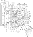
도 3은 도 1에 따른 전동식 압축기의 내부를 보인 단면도,
도 4는 도 3에서 이물질 차단부를 분해하여 보인 사시도,
도 5는 도 3에서 이물질 차단부에서 각 부분의 규격을 설명하기 위해 보인 단면도,
도 6은 도 3에 따른 이물질 차단부에 대한 다른 실시예를 보인 단면도,
도 7은 도 3에 따른 이물질 차단부에 대한 또다른 실시예를 보인 단면도,
도 8은 도 3에 따른 이물질 차단부에 대한 또다른 실시예를 보인 단면도,
도 9는 도 3에 따른 이물질 차단부에 대한 또다른 실시예를 보인 단면도,
도 10은 도 3에 따른 이물질 차단부의 설치위치에 대한 다른 실시예를 보인 단면도.1 is a perspective view showing the appearance of an electric compressor according to the present embodiment,
Figure 2 is an exploded perspective view of the electric compressor according to Figure 1,
Figure 3 is a cross-sectional view showing the interior of the electric compressor according to Figure 1,
4 is an exploded perspective view of the foreign material blocking unit in FIG. 3,
Figure 5 is a cross-sectional view shown to explain the specification of each part in the foreign matter blocking unit in Figure 3,
Figure 6 is a cross-sectional view showing another embodiment of the foreign matter blocking unit according to Figure 3,
Figure 7 is a cross-sectional view showing another embodiment of the foreign matter blocking unit according to Figure 3,
8 is a cross-sectional view showing another embodiment of the foreign matter blocking unit according to FIG. 3,
9 is a cross-sectional view showing another embodiment of the foreign matter blocking unit according to FIG. 3,
10 is a cross-sectional view showing another embodiment of the installation location of the foreign matter blocking unit according to FIG.
이하, 본 발명에 의한 전동식 압축기를 첨부도면에 도시된 일실시예에 의거하여 상세하게 설명한다.Hereinafter, an electric compressor according to the present invention will be described in detail based on an embodiment shown in the accompanying drawings.
도 1은 본 실시예에 따른 전동식 압축기의 외관을 보인 사시도이고, 도 2는 도 1에 따른 전동식 압축기를 분해하여 보인 사시도이며, 도 3은 도 1에 따른 전동식 압축기의 내부를 보인 단면도이다.1 is a perspective view showing the appearance of an electric compressor according to the present embodiment, FIG. 2 is a perspective view showing an exploded electric compressor according to FIG. 1, and FIG. 3 is a sectional view showing the interior of the electric compressor according to FIG. 1.
이들 도면을 참조하면, 본 실시예에 따른 모터에 의해 구동되는 스크롤 방식의 전동식 압축기(이하, 전동식 압축기로 약칭함)는, 냉매를 압축하는 압축기 모듈(101)과, 압축기 모듈(101)의 전방측에 결합되어 압축기 모듈(101)의 구동을 제어하는 인버터 모듈(201)로 이루어질 수 있다. 압축기 모듈(101)과 인버터 모듈(201)은 연속으로 조립되거나 또는 각각 독립적으로 제작된 후 조립될 수 있다. 본 실시예는 후자를 대표예로 삼아 설명하지만, 전자와 후자가 혼합된 형태로 압축기 모듈과 인버터 모듈을 독립적으로 제작되되 연속하여 조립될 수도 있다.Referring to these drawings, a scroll-type electric compressor (hereinafter abbreviated as an electric compressor) driven by a motor according to this embodiment includes a
압축기 모듈(101)은 내부공간이 모터실(S1)을 이루고 모터실에 연통되도록 흡기구(111)가 형성되는 메인 하우징(110), 메인 하우징(110)의 모터실(S1)에 고정되는 전동부인 구동모터(120), 메인 하우징(110)의 외부에서 구동모터(120)의 일측에 구비되고 그 구동모터(120)의 회전력을 이용하여 냉매를 압축하는 압축부(105), 압축부(105)의 타측에 결합되어 토출실(S2)을 형성하는 리어 하우징(160)을 포함한다. The
메인 하우징(110)은, 지면에 대해 횡방향으로 배치됨에 따라 구동모터(120)와 압축부(105)는 횡방향을 따라 배열되며, 구동모터(120)는 전방측에, 압축부(105)는 후방측에 각각 설치된다. 편의상 도 3의 좌측을 전방측, 우측을 후방측으로 지정하여 설명한다. The
메인 하우징(110)은, 전방단이 개구되고 후방단이 일부 막힌 컵 단면 형상으로 형성된다. 메인 하우징(110)의 개구된 전방단에는 후술할 인버터 하우징(210)이 결합되어 밀봉되고, 메인 하우징(110)의 막힌 후방단에는 압축부(105)를 지지하는 프레임부(112)가 일체로 연장 형성된다. 메인 하우징(110)의 프레임부(112)에는 후술할 회전축(130)의 메인 베어링부(132)가 관통되어 회전 가능하게 지지되는 제1 축수부(113)가 원통 형상으로 형성된다. The
제1 축수부(113)에는 부시베어링으로 된 제1 베어링(171)이 삽입되어 결합되고, 제1 축수부(113)의 내주면은 회전축(130)의 메인 베어링부(132)와 이격되어 후술할 배압실(S3)이 모터실(S1)과 연통될 수 있다. 메인 하우징(110)의 전방단 부근에 흡입관(미도시)이 연결되는 흡기구(111)가 형성됨에 따라, 본 실시예의 모터실(S1)은 일종의 흡입공간을 형성하게 된다. 따라서, 본 실시예에 따른 전동식 압축기는 냉매가 모터실을 이루는 메인 하우징의 내부공간을 통해 압축부로 흡입됨에 따라 저압식 압축기를 형성하게 된다.A
본 실시예에 따른 메인 하우징은 앞서 설명한 바와 같이 프레임부를 일체로 형성한다. 이에 따라, 메인 하우징에 프레임을 별도로 조립하는 과정을 배제하여 조립공수를 줄이는 동시에 구동모터의 조립성을 높일 수 있다.The main housing according to this embodiment integrally forms the frame portion as described above. Accordingly, a process of separately assembling the frame in the main housing can be excluded, thereby reducing the number of assembly steps and increasing the assembly of the drive motor.
한편, 구동모터(120)는, 메인 하우징(110)의 내주면에 삽입되어 고정되는 고정자(121)와, 고정자(121)의 내부에 위치하고 그 고정자(121)와의 상호작용에 의해 회전되는 회전자(122)를 포함한다. 회전자(122)에는 그 회전자(122)와 함께 회전하면서 구동모터(120)의 회전력을 압축부(105)에 전달하는 회전축(130)이 결합된다.On the other hand, the
고정자(121)는 메인 하우징(110)에 고정자 코어(1211)를 열박음(또는 열간압입)하여 고정하게 된다. 따라서, 고정자(121)는 메인 하우징(110)에서의 삽입 깊이를 작게 하는 것이 조립작업이 용이하게 될 뿐만 아니라, 고정자(121)를 열박음하는 과정에서 고정자(121)의 동심도를 유지하는데 유리할 수 있다.The
회전자(122)의 중앙에는 회전축(130)이 회전자 코어(1221)에 열박음(또는 열간압입)으로 결합된다. 회전축(130)은 구동모터(120)를 사이에 두고 양단을 반경방향으로 지지할 수도 있다. 하지만, 본 실시예와 같이 회전축(130)의 일단은 구동모터(120)의 일측, 즉 프레임부(112)와 고정스크롤(150)에서 반경방향으로 2점 지지되는 고정단이 되고, 구동모터(120)의 회전자(122)에 결합되는 회전축(130)의 타단은 반경방향으로 자유단이 될 수 있다.In the center of the
회전축(130)은 회전자(122)에 결합되는 축부(131), 제1 축수부(113)에 회전 가능하게 반경방향으로 지지되는 메인 베어링부(132), 선회스크롤(140)에 편심지게 결합되는 편심부(133), 고정스크롤(150)의 제2 축수부(156)에 회전 가능하게 반경방향으로 지지되는 서브 베어링부(134)가 형성된다. 메인 베어링부(132)와 서브 베어링부(134)는 앞서 설명한 바와 같이 회전축(130)을 각각 반경방향으로 지지하게 되고, 편심부(133)는 구동모터(120)의 회전력을 선회스크롤(140)에 전달하여 선회스크롤(140)이 올담링(180)에 의해 선회운동을 하게 된다.The
또, 도 3을 참조하면, 회전축(130)의 중간, 즉 메인 베어링부(132)와 편심부(133)의 사이에는 축방향 베어링돌부(135)가 반경방향으로 연장되어 형성될 수 있다. 축방향 베어링돌부(135)의 축방향 베어링면(135a)은 제1 축수부(113)의 축방향 베어링면(113a)과 함께 스러스트면을 이루게 된다. In addition, referring to Figure 3, the middle of the
또, 회전축(130)의 내부에는 후방단에서 전방단을 향하는 방향으로 기설정된 깊이만큼 중공된 제2 급유안내유로(136)가 형성되고, 제2 급유안내유로(136)의 중간에는 메인 베어링부(132), 편심부(133), 서브 베어링부(134)의 외주면을 향해 각각의 급유구멍들(137a)137b)(137c)이 형성된다. 이에 대해서는 나중에 급유구조와 함께 다시 설명한다.In addition, a second refueling
한편, 압축부(105)는 앞서 설명한 바와 같이, 프레임(130)에 축방향으로 지지되어 선회운동을 하는 선회스크롤(또는 제1 스크롤)(140)과, 선회스크롤(140)과 맞물려 결합되며 프레임(130)의 후방단에 고정 결합되는 고정스크롤(또는, 제2 스크롤)(150)을 포함한다. 선회스크롤(140)과 고정스크롤(150)의 사이에는 선회스크롤(140)의 선회운동시 두 개 한 쌍의 압축실(V)을 형성하게 된다. On the other hand, as described above, the
선회스크롤(140)은 프레임(130)의 후방면에 축방향으로 지지되고, 프레임(130)과 선회스크롤(140)의 사이에는 선회스크롤(140)의 자전을 방지하는 자전방지기구로서의 올담링(180)이 구비된다. 올담링(180)은 프레임(130)의 올담링 안착홈(133)에 삽입되어 구비되고, 자전방지기구는 올담링 뿐만 아니라 핀과 링으로 된 방식이 적용될 수도 있다.The
또, 선회스크롤(140)은 선회스크롤 경판부(이하, 선회경판부)(141)가 대략 원판모양으로 형성되고, 선회경판부(141)의 전방면에는 후술할 고정랩(153)과 맞물려 그 고정랩(153)을 기준으로 내측면과 외측면에 각각 압축실(V)을 이루는 선회랩(142)이 형성된다. In addition, the
선회경판부(141)에는 배압실(S3)과 중간압축실(V)을 연통시키는 배압구멍(141a)이 형성된다. 이에 따라, 배압실(S3)의 압력과 중간압축실의 압력 간 차이에 따라 오일 또는 냉매가 배압실(S3)과 중간압축실 사이를 이동하게 된다. The pivoting
또, 선회경판부(141)의 중심에는 회전축(125)의 편심부(125d)가 회전 가능하게 결합되는 회전축 결합부(143)가 관통 형성된다. 회전축 결합부(143)는 원통 형상으로 형성되고, 회전축 결합부(143)의 내부에는 회전축(125)의 편심부(125d)와 베어링면을 이루는 제3 베어링(173)이 삽입되어 결합된다. 이에 따라, 회전축 결합부(또는 제3 베어링)(143)는 선회랩(142)과 반경방향으로 중첩되도록 형성되고, 회전축 결합부(143)는 가장 안쪽에 형성되는 선회랩(142)의 일부가 된다. In addition, at the center of the turning
한편, 고정스크롤(150)은 앞서 설명한 바와 같이 메인 하우징(110)의 외부에서 프레임(130)의 후방면에 결합된다. 이 경우, 프레임(130)과 고정스크롤(150) 사이에는 오링 또는 가스켓과 같은 실링부재(108b)가 구비될 수 있다. 다만, 본 실시예와 같이 프레임(130)과 선회스크롤(140) 사이에 가스켓 플레이트(190)가 구비되는 경우에는 그 가스켓 플레이트(190)가 연장되어 일종의 가스켓 역할을 하는 실링부가 형성될 수 있다. 이 경우에는 별도의 실링부재가 구비되지 않을 수도 있고, 실링부의 양측에 오링과 같은 실링부재가 구비될 수도 있다. 이에 대해서는 나중에 다시 설명한다.On the other hand, the fixed
고정스크롤(150)은 고정스크롤 경판부(이하, 고정경판부)(151)가 대략 원판모양으로 형성되고, 고정경판부(151)의 전방측 가장자리에는 프레임(130)의 후방측 지지면(이하, 지지면으로 약칭함)(130a)에 결합되는 스크롤 측벽부(152)가 형성된다. In the fixed
스크롤 측벽부(152)는 환형으로 형성되고, 스크롤 측벽부(152)의 외주면은 고정스크롤(150)의 외벽을 이루며, 스크롤 측벽부(152)의 전방면(152a)은 후술할 실링부재(108c)를 사이에 두고 프레임(130)의 지지면(130a)에 결합된다. 스크롤 측벽부에 대해서는 실링부재와 함께 다시 설명한다.The
고정경판부(151)의 전방면에는 선회랩(142)과 맞물려 압축실(V)을 이루는 고정랩(153)이 형성된다. 고정랩(153)은 선회랩(142)과 함께 인볼류트 형상으로 형성될 수 있지만 그 외의 다양한 형상으로 형성될 수 있다. A fixed
예를 들어, 고정랩(153)은 선회랩(142)은 회전축(125)이 선회스크롤(140)의 중심을 관통하여 결합되는 경우에는 최종 압축실이 편심진 위치에 형성되면서 압축실 간 압력차가 크게 발생될 수 있다. 이는, 축관통 스크롤 압축기의 경우 최종 압축실이 스크롤의 중심으로부터 편심지게 형성되면서 한 쪽 압축실의 압력이 다른 쪽 압축실의 압력에 비해 크게 낮아지게 되기 때문이다. 따라서, 축관통 스크롤 압축기에서는 본 실시예와 같이 선회랩(142)과 고정랩(153)을 비 인벌류트 형상으로 형성하는 것이 유리하다. For example, the fixed
또, 스크롤 측벽부(152)에는 프레임(130)의 프레임측 흡입구멍(135)과 연통되어 냉매를 흡입실로 안내하는 스크롤측 흡입구멍(154)이 형성된다. 스크롤측 흡입구멍(154)은 고정랩(153)과 선회랩(142)이 비대칭형인 경우에는 한 개만 형성될 수도 있지만, 본 실시예와 같이 대칭형인 경우에는 복수 개가 형성될 수 있다.In addition, the scroll
또, 고정경판부(151)의 중앙부분에는 최종 압축실(V)을 후술할 토출실(S2)과 연통시켜 냉매의 토출을 안내하는 토출구(155)가 형성된다. 토출구(155)는 압축실(V)에서 토출실(S3)을 향해 고정경판부(151)의 축방향 또는 경사진 방향으로 관통 형성될 수 있다. 토출구(155)는 제1 압축실과 제2 압축실에 모두 연통되도록 한 개만 형성될 수도 있고, 제1 압축실과 제2 압축실에 독립적으로 연통될 수 있도록 제1 토출구와 제2 토출구가 형성될 수도 있다. In addition, a
또, 고정경판부(151)의 후방면에는 토출구(155)를 개폐하는 토출밸브(156)가 설치된다. 토출밸브(156)는 토추구(155)가 복수 개인 경우 낱개로 형성될 수도 있고, 복수 개가 일체로 형성될 수도 있다. In addition, a
또, 고정경판부(151)의 중심에는 회전축(125)의 서브 베어링부(125c)가 회전 가능하게 삽입되어 반경방향으로 지지되도록 제2 축수부(157)가 형성된다. 제2 축수부(157)는 고정경판부(151)에서 리어 하우징(160)을 향해 축방향으로 연장되어 형성될 수도 있고, 고정경판부(151)의 두께를 두껍게 확대하여 형성될 수도 있다. 하지만, 후자의 경우는 고정스크롤(150)의 무게가 증가할 뿐만 아니라, 불필요한 부분까지 두껍게 형성되면서 토출구(155)의 길이가 길어져 사체적이 증가할 수 있다. 따라서, 전자와 같이 고정경판부(151)의 일부를 돌출시키되, 예를 들어 토출구(155)가 형성되는 부분을 제외한 부분에 축방향으로 돌출시켜 제2 축수부(157)를 형성하는 것이 바람직하다. In addition, a
제2 축수부(157)는 후방면이 막힌 원통 형상으로 형성되어 내주면에는 회전축(125)의 서브 베어링부(125c)와 베어링면을 이루는 제2 베어링(172)이 삽입되어 결합된다. 제2 베어링(172)은 부시베어링으로 이루어질 수 있고, 니들베어링으로 이루어질 수도 있다. The
또, 제2 축수부(156)의 후방측 내부에는 회전축(130)의 단부보다 축방향으로 연장된 오일수용공간(156a)이 형성되고, 오일수용공간(156a)은 후술할 제1 급유안내유로(157a)와 제2 급유안내유로(136) 사이에 위치하게 된다. 제1 급유안내유로(157a)는 토출실(S2)에, 제2 급유안내유로(136)는 메인 베어링부(132), 서브 베어링부(134) 및 편심부(133)의 외주면들에 구비되는 각각의 베어링면으로 연통될 수 있다. In addition, an
제1 급유안내유로(157a)는 고정스크롤(150)에 형성될 수도 있고, 후술할 리어 하우징(160)에 형성될 수도 있다. 예를 들어, 제1 급유안내유로(157a)가 고정스크롤(150)의 형성되는 경우에는 고정스크롤(150)의 후방면, 즉 고정스크롤(150)의 축방향 양쪽 측면 중에서 프레임부(112)를 마주보는 면을 제1 면(150a), 제1 면(150a)의 반대쪽 면을 제2 면(150b)이라고 할 때, 제2 면(150b)에는 리어 하우징(160)을 향하는 방향으로 돌출되는 급유돌부(157)가 형성되고, 급유돌부(157)에 제1 급유안내유로(157a)가 반경방향으로 형성될 수 있다. 제1 급유안내유로(157a)의 일단은 후술할 급유통공(191a)을 통해 고정경판부(151)의 외주면에 연통되고, 제1 급유안내유로(157a)의 타단은 오일수용공간(156a)의 내주면에 연통되도록 형성될 수 있다. The first oil
이에 따라, 리어 하우징(160)의 토출실(S2)에서 냉매로부터 분리된 미스트 상태인 고압의 오일(이하, 냉매오일)은 압력차에 의해 제1 급유안내유로(157a)를 따라 오일수용공간(156a)으로 신속하게 이동하게 되고, 이 냉매오일은 압력차에 의해 제2 급유안내유로(136)와 각각의 급유구멍(137a~137c)을 통해 각각의 베어링면으로 신속하게 공급될 수 있다. 제1 급유안내유로에 대해서는 나중에 이물질 차단부와 함께 다시 설명한다.Accordingly, in the discharge chamber S2 of the
다시 도 3을 참조하면, 회전축(130)에는 한 개의 제1 급유안내유로(136)와 복수 개의 급유구멍(137a)(137b)(137c)이 형성될 수 있다. 앞서 설명한 바와 같이, 제1 급유안내유로(136)는 회전축(130)의 단부, 즉 오일수용공간(156a)에 수용된 회전축(130)의 후방단에서 전방단 방향으로 소정의 깊이만큼 축방향으로 형성되고, 복수 개의 급유구멍(137a)(137b)(137c)은 제1 급유안내유로(136)의 중간에서 축방향을 따라 일정 간격을 두고 형성될 수 있다.Referring back to FIG. 3, one first
복수 개의 급유구멍(137a)(137b)(137c)은 서브 베어링부(134)의 외주면으로 관통되는 제2 급유구멍(137b), 편심부(133)의 외주면으로 관통되는 제3 급유구멍(137c), 메인 베어링부(132)의 외주면으로 관통되는 제1 급유구멍(137a)으로 이루어질 수 있다. The plurality of oiling
이에 따라, 오일수용공간(156a)에서 제1 급유안내유로(136)로 유입되는 냉매오일은 제2 급유구멍(137b), 제3 급유구멍(137c), 제1 급유구멍(137a)을 차례대로 통과하여 각각의 베어링면으로 공급되게 된다. Accordingly, the refrigerant oil flowing into the first
리어 하우징(160)은 고정스크롤(150)의 후방면에 결합된다. 리어 하우징(160)의 전방면에는 고정스크롤(150)의 후방면과 함께 토출실(S2)을 형성한다. 리어 하우징(160)에는 토출실(S2)과 연통되어 그 토출실(S2)로 토출된 냉매를 배출하는 배기구(161)가 형성되며, 배기구(161)에는 유분리기(미도시)가 설치될 수 있다. The
한편, 메인 하우징(110)의 양단 중에서 리어 하우징(160)의 반대쪽, 즉 메인 하우징(110)의 개구단을 이루는 전방단에는 인버터 하우징(210)이 결합되어 복개될 수 있다. On the other hand, the
다시 도 1 내지 도 3을 참조하면, 인버터 하우징(210)은 인버터 모듈(201)의 일부를 이루는 것으로, 인버터 하우징(210)은 인버터 커버(220)와의 사이에 인버터실(S4)을 형성하게 된다. Referring back to FIGS. 1 to 3, the
인버터실(S4)에는 기판 및 인버터 소자와 같은 인버터 부품(230)을 수용하게 되고, 인버터 하우징(210)과 인버터 커버(220)는 볼트 체결된다. 인버터 커버(220)는 인버터 하우징(210)이 메인 하우징(110)에 먼저 조립된 후 나중에 인버터 하우징(210)에 조립될 수도 있고, 인버터 하우징(210)과 인버터 커버(220)가 먼저 조립된 후에 인버터 하우징(210)을 메인 하우징(110)에 조립될 수도 있다. 전자와 후자는 인버터 하우징(210)을 메인 하우징(110)에 조립하는 방식에 따라 구분될 수 있다.The inverter room S4 accommodates the inverter components 230 such as a substrate and an inverter element, and the
도면중 미설명 부호인 114는 제1 돌출부, 114a는 제1 유로, 138은 밸런스 웨이트, 154는 제2 돌출부, 154a는 제2 유로, 162는 지지돌부이다.In the drawing,
상기와 같은 본 실시예에 의한 전동식 압축기는 다음과 같이 동작한다. The electric compressor according to the present embodiment as described above operates as follows.
즉, 구동모터(120)에 전원이 인가되면, 회전축(130)이 회전자(122)와 함께 회전을 하면서 선회스크롤(140)에 회전력을 전달하게 되고, 선회스크롤(140)은 올담링(180)에 의해 선회운동을 하게 된다. 그러면 압축실(V)은 중심측을 향해 지속적으로 이동되면서 체적이 감소하게 된다.That is, when power is applied to the
그러면, 냉매는 흡기구(101a)를 통해 흡입공간인 모터실(S1)로 유입되고, 모터실(S1)로 유입된 냉매는 고정자(121)의 외주면과 메인 하우징(110)의 내주면에 형성되는 유로 또는 고정자(121)와 회전자(122) 사이의 공극을 통과하여 메인 하우징(110)과 고정스크롤(150)에 구비되는 흡입유로(Fg)를 통해 압축실(V)로 흡입된다. Then, the refrigerant flows into the motor chamber S1 which is the suction space through the intake port 101a, and the refrigerant flowing into the motor chamber S1 flows through the outer circumferential surface of the
그러면, 이 냉매는 선회스크롤(140)과 고정스크롤(150)에 의해 압축되어 토출구(155)를 통해 토출실(S2)로 토출되고, 이 냉매는 토출실(S2)에서 오일이 분리된다. 오일이 분리된 냉매는 배기구(161)를 통해 냉동사이클로 배출되는 반면 미스트 상태의 냉매오일은 급유통로를 이루는 제1 급유안내유로(157a), 오일수용공간(156a), 제2 급유안내유로(136), 급유구멍(137a~137c)을 통해 각각의 베어링면으로 공급되며, 이 냉매오일의 일부는 배압실(S3)로 유입되어 선회스크롤(140)을 고정스크롤(150)쪽으로 지지하는 배압력을 형성하게 된다. Then, the refrigerant is compressed by the
그러면, 선회스크롤(140)은 배압실(S3)의 배압력에 의해 고정스크롤(150)을 향하는 방향으로 지지되어 선회스크롤(140)과 고정스크롤(150) 사이의 압축실(V)을 실링하게 된다. 이때, 배압실(S3)의 냉매오일 중에서 일부 냉매오일은 선회경판부(141)에 구비된 배압구멍(141a)을 통해 압축실(V)로 유입되는 한편, 일부 냉매오일은 메인 베어링부(132)와 제1 베어링(171) 사이를 통해 모터실(S1)로 유출되어 앞서 설명한 바와 같이 배압실(S3)이 유동압력을 형성하도록 하는 일련의 과정을 반복하게 된다.Then, the
한편, 본 발명에 따른 전동식 압축기에서는, 앞서 설명한 바와 같이 토출실에서 냉매로부터 분리된 냉매오일이 제1 급유안내유로를 통해 제2 축수부에 구비된 오일수용공간으로 유입되게 된다. On the other hand, in the electric compressor according to the present invention, as described above, the refrigerant oil separated from the refrigerant in the discharge chamber flows into the oil receiving space provided in the second water-reducing portion through the first oil supply guide passage.
이때, 이물질이 냉매오일에 혼입되어 오일수용공간으로 유입되고, 이 이물질은 회전축의 제2 급유안내유로와 급유구멍으로도 유입되게 된다. 그러면, 급유구멍과 같이 내경이 작은 구멍이 이물질에 의해 막히거나, 또는 급유구멍을 통과하여 각각의 베어링면에서 축적될 경우에는 베어링면의 마모를 발생시키거나 일부 베어링면으로의 오일 공급이 원활하게 이루어지지 않을 수도 있다.At this time, the foreign material is mixed into the refrigerant oil and flows into the oil receiving space, and the foreign material also flows into the second oiling guide passage and the oiling hole of the rotating shaft. Then, when a hole with a small inner diameter, such as a lubrication hole, is blocked by a foreign substance or accumulates at each bearing surface through the lubrication hole, wear of the bearing surface occurs or oil supply to some bearing surfaces is smooth. It may not be achieved.
이를 감안하여, 본 발명에서는 제1 급유안내유로에 이물질 차단부를 형성하여, 토출실에서 오일수용공간으로 이동하는 냉매오일에 이물질이 혼입되더라도 그 이물질이 오일수용공간으로 유입되는 것을 미연에 방지할 수 있다.In view of this, in the present invention, a foreign matter blocking portion is formed in the first oil supply guide flow path, and even if foreign matter is mixed into the refrigerant oil moving from the discharge chamber to the oil receiving space, it is possible to prevent the foreign matter from entering the oil receiving space. have.
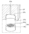
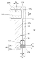
도 4는 도 3에서 이물질 차단부를 분해하여 보인 사시도이고, 도 5는 도 3에서 이물질 차단부에서 각 부분의 규격을 설명하기 위해 보인 단면도이다. FIG. 4 is a perspective view of the foreign material blocking unit shown in FIG. 3 in an exploded view, and FIG. 5 is a cross-sectional view illustrating the standard of each part in the foreign material blocking unit in FIG. 3.
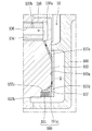
도 4 및 도 5를 참조하면, 본 실시예에 따른 이물질 차단부(190)는 복수 개의 급유통공(191a)이 형성되어 토출실(S2)과 제2 축수부(156)의 내부인 오일수용공간(156a)의 사이에 구비될 수 있다. 4 and 5, the foreign
예를 들어, 본 실시예에 따른 이물질 차단부(190)는 복수 개의 급유통공(191a)을 가지는 필터링부재(191)가 제1 급유안내유로(157a)에 삽입되어 결합될 수 있다. 필터링부재(190)는 도면에서와 같이 제1 급유안내유로(157a)의 입구단에 결합될 수도 있고, 경우에 따라서는 제1 급유안내유로(157a)의 중간 또는 출구단에 구비할 수도 있다. 다만, 가공이나 조립 측면에서 보면 필터링부재(191)는 제1 급유안내유로(157a)의 입구단에 결합하는 것이 가장 용이할 수 있다.For example, the foreign
이를 위해, 제1 급유안내유로(157a)의 입구단에는 필터링부재(191)가 삽입되어 결합되도록 필터링부재 장착홈(157b)이 형성될 수 있다. 필터링부재 장착홈(157b)의 내경(D1)은 제1 급유안내유로(157a)의 내경(D2)보다 크게 형성될 수 있다. 특히, 제1 급유안내유로(157a)의 내경(D2)이 제2 급유안내유로(136)의 내경(D3)보다 작게 형성되는 경우에는 필터링부재 장착홈(157b)의 내경(D1)은 제1 급유안내유로(157a)의 내경(D2)보다 훨씬 크게 형성될 수 있다. To this end, the filtering
또, 제1 급유안내유로(157a)와 필터링부재 장착홈(157b)의 사이에는 복수 개의 급유통공(191a)을 통과하는 냉매오일이 제1 급유안내유로(157a)로 원활하게 안내될 수 있도록 급유안내공간(157c)이 단차지게 형성될 수 있다. 급유안내공간(157c)의 내경(D5)은 필터링부재 장착홈(157b)의 내경(D1)보다 작고 제1 급유안내유로(157a)의 내경(D2)보다 크게 형성될 수 있다. 이에 따라, 제1 급유안내유로(157a)는 급유안내공간(157c)의 중앙에 연통되도록 형성될 수 있다. 급유안내공간(157c)은 도면에서와 같이 동일한 깊이로 형성될 수도 있지만, 경우에 따라서는 제1 급유안내유로(157a)쪽으로 갈수록 깊어지는 테이펴 형상으로 형성될 수도 있다.In addition, between the first
다시 도 5를 참조하면, 필터링부재(191)에는 앞서 설명한 복수 개의 급유통공(191a)이 관통 형성될 수 있다. 복수 개의 급유통공(191a)은 서로 동일한 방향, 즉 길이방향으로 관통 형성될 수 있다.Referring to FIG. 5 again, the filtering
급유통공(191a)의 내경(D6)은 제1 급유안내유로(157a)의 내경(D2)에 비례하여 형성될 수 있다. 예를 들어, 급유통공(191a)의 내경이 제1 급유안내유로(157a)의 내경(D2)보다 너무 크게 형성되게 되면, 급유통공(191a)을 통과한 이물질이 제1 급유안내유로(157a)에 걸려 제1 급유안내유로(157a)가 막힐 수 있다. 이에 따라, 급유통공(191a)의 내경(D6)은 제1 급유안내유로(157a)의 내경(D2)보다 작거나 같게 형성되는 것이 바람직할 수 있다.The inner diameter D6 of the
또, 급유통공(191a)의 내경(D6)은 제2 급유안내유로(136)의 내경(D3)이나 급유구멍(191a)의 내경(D6)에 비례하여 형성될 수도 있다. 예를 들어, 급유통공(191a)의 내경(D6)이 제2 급유안내유로(136) 또는 급유구멍(137a~137c)의 내경(D4)보다 크게 형성되게 되면, 급유통공(191a)을 통과한 이물질이 제2 급유안내유로(136) 또는 급유구멍(137a~137c)에 걸려 막힐 수 있다. 이에 따라, 급유통공(191a)의 내경(D6)은 제2 급유안내유로(136)의 내경(D3)보다 작고, 급유구멍(191a)의 내경(D6)보다 작거나 같게 형성되는 것이 바람직할 수 있다.In addition, the inner diameter D6 of the
도 4와 같이, 필터링부재(191)의 외형은 원형 단면 형상으로 형성될 수 있다. 하지만, 필터링부재(191)의 외형은 반드시 원형일 필요는 없다. 예를 들어, 사각형이나 오각형 등 다양한 각진 형상으로 형성될 수 있다. 4, the outer shape of the
또, 필터링부재(191)는 축방향 길이(H1)가 반경방향 길이(즉, D1)보다 길게 형성될 수도 있고, 짧게 형성될 수도 있다. 필터링부재(191)가 축방향 길이(H1)가 반경방향 길이(D1)보다 길게 형성되게 되면 그 필터링부재(191)에 구비된 복수 개의 급유통공(191a)이 일종의 감압부를 형성하게 된다. 그러면 감압길이가 길어짐에 따라, 제1 급유안내유로(157a)의 직경(D2)을 상대적으로 넓게 형성하더라도 냉매오일을 적정하게 감압시킬 수 있다. 반면, 필터링부재(191)가 축방향 길이(H1)가 반경방향 길이(D1)보다 짧게 형성되게 되면, 상대적으로 감압효과는 떨어지게 된다. 하지만 급유통공(191a)에 이물질이 누적되어 막힐 우려는 감소하게 된다. 따라서, 필터링부재(191)의 축방향 길이(H1)는 대략 반경방향 길이(D1)와 같거나 약간 짧게 형성될 수 있다. In addition, the filtering
또, 필터링부재(191)는 외주면이 필터링부재 장착홈(157b)의 내주면에 압입되거나 나사 체결될 수 있다. 필터링부재(191)는 재질이나 형상에 따라 다양하게 결합될 수 있다. 예를 들어, 필터링부재(191)가 금속인 경우에는 압입이나 용접 또는 나사 체결될 수 있고, 수지계열인 경우에는 접합이나 나사 체결될 수 있다.Also, the filtering
한편, 제1 급유안내유로는 그 내경과 길이를 조절하여 제1 급유안내유로가 감압부를 형성하도록 할 수 있다. On the other hand, by adjusting the inner diameter and the length of the first oil supply guide channel, the first oil supply guide channel can be formed to form a depressurization portion.
예를 들어, 제1 급유안내유로(157a)의 내경(D2)이 급유통공(191a)의 내경(D6)과 동일하게 형성되거나 또는 급유통로(191a)의 내경(D6)보다는 크고 제2 급유안내유로(136)의 내경(D3)보다 작게 형성되는 경우에는 제1 급유안내유로(157a)의 길이(H2)를 적어도 급유통공(191a)의 길이(H1)보다는 길게 형성할 수 있다. 이를 통해 제1 급유안내유로(157a)를 통과하는 냉매오일의 압력을 토출압보다 낮고 흡입압보다는 높은 중간압으로 감압되도록 할 수 있다.For example, the inner diameter D2 of the first oil
상기와 같이, 제1 급유안내유로(157a)가 위치하는 부분에서 감압부가 형성됨에 따라, 급유통로에 별도의 감압부를 형성할 필요가 없게 되고, 이에 따라 회전축을 비롯한 다른 부품의 조립을 용이하게 할 수 있다. As described above, as the depressurization portion is formed at the portion where the first oil supply
또, 감압부가 냉매오일의 유동순서를 기준으로 볼 때 회전축(130)이 접하는 부분, 즉 제2 축수부(156)보다 앞단에 형성됨에 따라, 회전축(130)이 접하는 오일수용공간(156)의 내 압력은 이미 중간압으로 감압된 상태가 된다. 그러면, 오일수용공간(156) 내 냉매오일의 압력에 의해 회전축(130)이 전방쪽으로 받는 축방향 하중이 감소되면서 축방향 마찰손실이 낮아져 압축기 효율이 향상될 수 있다.In addition, when the depressurization portion is formed based on the flow order of the refrigerant oil, the portion where the
한편, 급유구멍을 이용하여 감압부를 형성할 수도 있다. 도 6은 도 3에 따른 전동식 압축기에서, 이물질 차단부에 대한 다른 실시예를 보인 단면도이다. On the other hand, it is also possible to form a depressurization portion using the oil supply hole. 6 is a cross-sectional view showing another embodiment of the foreign matter blocking unit in the electric compressor according to FIG. 3.
도 6을 참조하면, 급유구멍(191a)의 길이(H1)를 길게 형성하여 감압부를 형성할 수도 있다. 이 경우에는 제1 급유안내유로(157a)의 내경을 작게 형성할 필요가 없고, 길이를 길게 형성할 필요도 없다. 즉, 본 실시예에 따른 이물질 차단부는 전술한 이물질 차단부와 기본적인 구조와 그에 따른 작용 효과는 유사하다. 다만, 본 실시예에서는 급유구멍(191a)의 길이(H1)가 제1 급유안내유로(157a)의 길이(H2)보다 길게 형성된다. 이에 따라, 따라서, 제1 급유안내유로(157a)의 가공이 용이하게 되어 전체적으로 이물질 차단부를 용이하게 형성할 수 있다.Referring to FIG. 6, a length H1 of the
한편, 전술한 실시예들에서는 제1 급유안내유로 또는 급유구멍의 크기와 길이를 조절하여 감압부를 형성하는 것이나, 급유통로에 감압핀과 같은 감압부재를 삽입하여 감압부를 형성할 수도 있다. 도 7은 도 3에 따른 전동식 압축기에서, 이물질 차단부에 대한 또다른 실시예를 보인 단면도이다. On the other hand, in the above-described embodiments, the pressure reducing part may be formed by adjusting the size and length of the first oiling guide passage or the oiling hole, or a pressure reducing member such as a pressure reducing pin may be inserted into the oiling passage. 7 is a cross-sectional view showing another embodiment of the foreign matter blocking unit in the electric compressor according to FIG. 3.
도 7을 참조하면, 본 실시예에 따른 제1 급유안내유로(157a)에는 기설정된 단면적과 길이를 가지는 감압부재(192)가 삽입되어 감압부를 형성할 수도 있다. Referring to FIG. 7, a pressure-reducing
이 경우, 제1 급유안내유로(157a)의 내경(D2)은 급유통공(191a)의 내경(D6)보다 크게 형성되는 반면, 제2 급유안내유로(136)의 내경(D3)보다 크거나 같게 형성될 수 있다. 제1 급유안내유로(157a)의 내주면과 감압부재(192)의 외주면 사이에 형성되는 급유통로의 단면적(A)은 급유통공(191a)의 단면적(B)보다 크거나 같게 형성될 수 있다.In this case, the inner diameter D2 of the first
상기와 같이 감압부재를 삽입하여 감압부를 형성하게 되면 제1 급유안내유로(157a)의 내경(D2)을 크게 형성할 수 있게 된다. 이에 따라, 제1 급유안내유로(157a)에 대한 가공이 용이하게 되어 제1 급유안내유로(157a)를 길게 형성할 수 있고, 이를 통해 감압유로의 길이를 증가시켜 감압효과를 높일 수 있다.When the pressure-reducing member is inserted to form the pressure-reducing portion as described above, the inner diameter D2 of the first oil
한편, 전술한 실시예들에서는 제1 급유안내유로가 고정스크롤에 형성되는 것이나, 경우에 따라서는 제2 급유안내유로가 형성된 별도의 커버부재를 제작하여 고정스크롤의 급유돌부 전면에 결합할 수도 있다. On the other hand, in the above-described embodiments, the first refueling guide passage is formed on the fixed scroll, but in some cases, a separate cover member on which the second refueling guide passage is formed may be manufactured and coupled to the front of the refueling protrusion of the fixed scroll. .
도 8은 도 3에 따른 전동식 압축기에서, 이물질 차단부에 대한 또다른 실시예를 보인 단면도이다. 8 is a cross-sectional view showing another embodiment of the foreign matter blocking unit in the electric compressor according to FIG. 3.
도 8을 참조하면, 고정스크롤(150)의 급유돌부(157)에는 필터링부재 장착홈(157b)과 급유안내공간(157c), 그리고 오일수용공간(156a)이 형성되고, 급유돌부(157)에 결합되는 커버부재(193)에는 제2 급유안내유로(193a)가 반경방향으로 길게 형성될 수 있다. 제2 급유안내유로(193a)의 양단이 각각 급유안내공간(157c)과 오일수용공간(156a)에 각각 연통되도록 고정스크롤(150)의 급유돌부(157)에는 제1 안내구멍(157d) 및 제2 안내구멍(157e)이 각각 형성될 수 있다.Referring to FIG. 8, the lubricating
상기와 같이, 별도의 커버부재(193)에 제2 급유안내유로(193a)가 홈 형상으로 형성되는 경우에는 고정스크롤(150)에 제1 급유안내유로를 구멍 형상으로 형성하는 것에 비해 가공이 상대적으로 용이할 수 있다. 이에 따라, 제2 급유안내유로(193a)의 단면적을 작게 형성하면서도 길이를 길게 형성할 수 있어 제2 급유안내유로(156a)에서의 냉매오일 압력을 효과적으로 감압시킬 수 있다. As described above, when the second
도면으로 도시하지는 않았으나, 커버부재에 제1 급유안내유로를 형성하여 감압핀을 삽입함으로써 감압부를 형성할 수도 있다. 이 경우에도 종래와 같이 고정스크롤에 제1 급유안내유로를 형성하여 감압핀을 삽입하는 것에 비해 가공을 용이하게 할 수 있다. Although not shown in the drawing, a pressure reducing portion may be formed by forming a first oil supply guide passage in the cover member and inserting the pressure reducing pin. Even in this case, it is possible to facilitate processing compared to inserting the pressure-reducing pin by forming the first oil supply guide passage on the fixed scroll as in the prior art.
한편, 전술한 실시예들에서는 필터링부재를 별도로 제작하여 제1 급유안내유로에 삽입하여 결합하는 것이나, 경우에 따라서는 별도의 필터링부재를 제작하여 후조립하지 않고 고정스크롤의 급유돌부에 급유통공을 직접 형성할 수도 있다. On the other hand, in the above-described embodiments, the filtering member is separately manufactured and inserted into the first oiling guide flow path to be combined, but in some cases, a separate filtering member is produced and the refueling hole is provided to the oiling protrusion of the fixed scroll without post-assembly. It can also be formed directly.
도 9는 도 3에 따른 전동식 압축기에서, 이물질 차단부에 대한 또다른 실시예를 보인 단면도이다. 9 is a cross-sectional view showing another embodiment of the foreign matter blocking unit in the electric compressor according to FIG. 3.
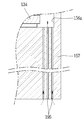
도 9를 참조하면, 본 실시예에 따른 이물질 차단부는, 고정스크롤(150)의 급유돌부(157)에 이물질 차단부를 이루도록 복수 개의 급유통공(195)이 형성될 수 있다. 복수 개의 급유통공(195)은 토출실(S2)에서 오일수용공간(156a)으로 연통되도록 동일한 방향으로 형성될 수 있다. Referring to FIG. 9, the foreign matter blocking unit according to the present exemplary embodiment may include a plurality of oil supply through
예를 들어, 급유통공(195)의 일단은 토출실(S2)에 연통되고, 급유통공(195)의 타단은 제2 축수부의 내주면인 오일수용공간(156a)에 연통되도록 형성될 수 있다. For example, one end of the
이 경우, 급유통공(195)은 평면투영시 직교하는 양쪽 방향으로 동일한 개수와 크기로 형성될 수도 있지만, 제2 축수부(156)의 길이방향에 해당하는 방향의 개수를 작게 형성하는 것이 제2 축수부(156)의 길이가 과도하게 길어지는 것을 억제할 수 있어 바람직할 수 있다.In this case, the
본 실시예에 따른 급유통공은 앞서 설명한 필터링부재에 구비되는 급유통공과 동일하게 형성될 수 있다. 다만, 본 실시예는 고정스크롤의 급유돌부에 급유통공을 직접 형성함에 따라, 급유통공의 개수를 줄이고 크기를 확대하는 것이 바람직할 수 있다. The lubrication hole according to the present embodiment may be formed in the same manner as the lubrication hole provided in the filtering member described above. However, in this embodiment, as the oil supply through hole is directly formed in the oil supply protrusion of the fixed scroll, it may be desirable to reduce the number of oil supply holes and enlarge the size.
상기와 같이, 급유통공이 고정스크롤에 일체로 형성되면, 종래와 달리 필터링부재는 물론 그 필터링부재가 장착될 필터링부재 장착홈 및 급유안내공간을 고정스크롤의 급유돌부에 가공할 필요가 없다. 또, 작은 필터링부재를 필터링부재 장착홈에 삽입하여 조립하는 공정을 배제할 수 있어 그만큼 압축기의 제조공정을 간소화할 수 있다.As described above, when the oil supply through hole is integrally formed on the fixed scroll, there is no need to process the filtering member mounting groove and the oil supply guide space to which the filtering member is to be mounted, as well as the filtering member, unlike the conventional one. In addition, the process of inserting and assembling the small filtering member into the filtering member mounting groove can be excluded, thereby simplifying the manufacturing process of the compressor.
한편, 본 발명에 따른 이물질 차단부의 설치위치에 대한 다른 실시예가 있는 경우는 다음과 같다. 즉, 전술한 실시예에서는 이물질 차단부가 고정스크롤에 구비되는 것이나, 본 실시예에서는 이물질 차단부가 리어 하우징에 형성되는 것이다.On the other hand, if there is another embodiment of the installation location of the foreign matter blocking portion according to the present invention is as follows. That is, in the above-described embodiment, the foreign substance blocking portion is provided on the fixed scroll, but in this embodiment, the foreign substance blocking portion is formed on the rear housing.
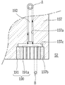
도 10은 도 3에 따른 이물질 차단부의 설치위치에 대한 다른 실시예를 보인 단면도이다.10 is a cross-sectional view showing another embodiment of the installation location of the foreign matter blocking unit according to FIG. 3.
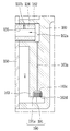
도 10을 참조하면, 리어 하우징(160)의 전방면에 축수부(162)가 고정스크롤(150)의 제2 면을 향해 돌출 형성되고, 축수부(162)의 하단에는 급유돌부(163)가 반경방향으로 길게 형성된다. Referring to FIG. 10, a water-reducing
또, 축수부(162)의 내부에는 오일수용공간(162a)이 형성되고, 급유돌부(163)에는 제1 급유안내유로(163a)가 형성되며, 제1 급유안내유로(163a)의 입구단에는 필터링부재 장착홈(163b)과 급유안내공간(163c)이 단차지게 형성된다. 급유안내공간(163c)의 중간에 제1 급유안내유로(163a)가 연통된다.In addition, an
필터링부재 장착홈(163b)에는 이물질 차단부(190)를 이루는 필터링부재(191)가 삽입되어 결합되고, 필터링부재(191)에는 복수 개의 급유구멍(191a)이 길이방향으로 관통되어 형성된다.A filtering
본 실시예에 따른 전동식 압축기에서 각 구성요소에 대한 구성과 그에 따른 작용 효과는 앞서 설명한 실시예들과 비교하여 그 형성위치만 고정스크롤에서 리어 하우징으로 바뀌었을 뿐 동일하게 형성될 수 있다. In the electric compressor according to the present embodiment, the configuration for each component and the effect of the action can be formed in the same manner as only the formation position thereof is changed from the fixed scroll to the rear housing compared to the above-described embodiments.
나아가, 이물질 차단부를 이루기 위한 실시예들 역시 앞서 설명한 고정스크롤에 적용된 경우와 동일하게 구성될 수 있다. 다만, 본 실시예와 같이 급유통로 및 이물질 차단부가 리어 하우징에 구비될 경우에는 고정스크롤에 대한 가공이 단순하게 될 수 있다. 이에 따라, 리어 하우징에 비해 상대적으로 높은 정밀도를 요구하는 고정스크롤에 대한 가공을 단순화하여 고정스크롤의 가공오차를 줄일 수 있다.Furthermore, the embodiments for forming the foreign matter blocking portion may also be configured in the same way as when applied to the fixed scroll described above. However, in the case where the oil supply passage and the foreign matter blocking portion are provided in the rear housing as in the present embodiment, the processing for the fixed scroll may be simplified. Accordingly, it is possible to reduce the processing error of the fixed scroll by simplifying the processing for the fixed scroll that requires relatively high precision compared to the rear housing.
Claims (14)
상기 회전자에 결합되는 회전축;
상기 구동모터의 일측에 구비되고, 상기 회전축이 축방향으로 관통하여 편심지게 결합되며, 상기 회전축에 의해 선회운동을 하는 제1 스크롤;
상기 제1 스크롤에 결합되어 그 제1 스크롤과 함께 압축실을 형성하며, 상기 제1 스크롤을 관통하는 회전축이 회전 가능하게 삽입되어 결합되는 제2 스크롤;
상기 제2 스크롤의 일측에 구비되며, 상기 제2 스크롤과 함께 토출실을 형성하는 리어 하우징;
상기 제2 스크롤 또는 상기 리어 하우징에 구비되어 상기 회전축을 반경방향으로 지지하는 축수부; 및
복수 개의 급유통공이 형성되어 상기 토출실과 상기 축수부의 내부 사이에 구비되는 이물질 차단부;를 포함하는 것을 특징으로 하는 전동식 압축기.A drive motor having a stator and a rotor;
A rotating shaft coupled to the rotor;
A first scroll provided on one side of the driving motor, the rotating shaft penetrating in an axial direction, eccentrically coupled, and pivoting by the rotating shaft;
A second scroll coupled to the first scroll to form a compression chamber together with the first scroll, and a rotation axis passing through the first scroll is rotatably inserted and coupled;
A rear housing provided on one side of the second scroll and forming a discharge chamber together with the second scroll;
A shaft number part provided on the second scroll or the rear housing to radially support the rotating shaft; And
And a plurality of refueling holes are formed to provide a foreign material blocking portion provided between the discharge chamber and the inside of the water-reducing portion.
상기 제2 스크롤 또는 상기 리어 하우징에는 상기 토출실과 상기 축수부의 내부 사이를 연통시키는 제1 급유안내유로가 형성되고,
상기 이물질 차단부는 상기 제1 급유안내유로에 구비되는 것을 특징으로 하는 전동식 압축기.According to claim 1,
The second scroll or the rear housing is formed with a first oil supply guide passage communicating between the discharge chamber and the inside of the water-reducing portion,
The foreign matter blocking unit is an electric compressor, characterized in that provided in the first oil supply guide passage.
상기 이물질 차단부는 상기 복수 개의 급유통공이 구비되어 상기 제1 급유안내유로에 결합되는 필터링부재로 이루어지며,
상기 급유통공은 적어도 한 개가 상기 제1 급유안내유로와 연통되도록 형성되는 것을 특징으로 하는 전동식 압축기.According to claim 2,
The foreign matter blocking unit is formed of a filtering member provided with the plurality of refueling holes and coupled to the first refueling guide channel,
The refueling hole is an electric compressor, characterized in that at least one is formed to communicate with the first refueling guide passage.
상기 급유통로의 길이는 상기 제1 급유안내유로의 길이보다 짧게 형성되는 것을 특징으로 하는 전동식 압축기.According to claim 3,
The length of the oil supply passage is an electric compressor, characterized in that formed shorter than the length of the first oil supply guide passage.
상기 급유통로의 길이는 상기 제1 급유안내유로의 길이보다 길게 형성되는 것을 특징으로 하는 전동식 압축기.According to claim 3,
The length of the oil supply passage is an electric compressor, characterized in that formed longer than the length of the first oil supply guide passage.
상기 제1 급유안내유로의 일단에는 상기 필터링부재가 삽입되는 필터링부재 장착홈이 형성되고,
상기 제1 급유안내유로와 연통되는 상기 필터링부재 장착홈의 내측 단부에는 상기 복수 개의 급유통공들과 연통되도록 급유안내공간이 형성되며,
상기 급유안내공간의 내경은 상기 필터링부재 장착홈의 내경보다는 작고 상기 제1 급유안내유로의 내경보다는 크게 형성되는 것을 특징으로 하는 전동식 압축기.According to claim 3,
A filtering member mounting groove into which the filtering member is inserted is formed at one end of the first oiling guide passage,
A refueling guide space is formed at an inner end of the filtering member mounting groove communicating with the first refueling guide passage so as to communicate with the plurality of refueling holes,
The inner diameter of the lubrication guide space is smaller than the inner diameter of the filtering member mounting groove and is characterized in that it is formed larger than the inner diameter of the first lubrication guide passage.
상기 급유통공의 내경은 상기 제1 급유안내유로의 내경보다 작거나 같게 형성되는 것을 특징으로 하는 전동식 압축기.The method of claim 6,
The inner diameter of the oil supply passage is smaller than or equal to the inner diameter of the first oil supply guide passage, the electric compressor.
상기 제1 급유안내유로는 상기 제2 스크롤 또는 상기 리어 하우징의 내부에 구멍 형상으로 관통 형성되는 것을 특징으로 하는 전동식 압축기.The method of claim 7,
The first oil supply guide passage is an electric compressor, characterized in that through-hole formed in the interior of the second scroll or the rear housing.
상기 제1 급유안내유로는 상기 제2 스크롤의 일측면 또는 상기 제2 스크롤이 마주보는 상기 리어 하우징의 일측면에 홈 형상으로 형성되고, 상기 제2 스크롤 또는 상기 리어 하우징에 결합되는 커버부재가 상기 홈을 복개하는 것을 특징으로 하는 전동식 압축기.The method of claim 7,
The first refueling guide passage is formed in a groove shape on one side of the second scroll or on one side of the rear housing facing the second scroll, and the cover member coupled to the second scroll or the rear housing is the An electric compressor, characterized in that the groove is retracted.
상기 제1 급유안내유로의 내부에는 상기 제1 급유안내유로의 내경보다 작은 외경을 가지는 감압부재가 삽입되는 것을 특징으로 하는 전동식 압축기.The method of claim 6,
An electric compressor, characterized in that a pressure-reducing member having an outer diameter smaller than the inner diameter of the first oil supply guide passage is inserted into the first oil supply guide passage.
상기 제1 급유안내유로의 내주면과 상기 감압부재의 외주면 사이에 형성되는 급유통로의 단면적은 상기 각 급유통공의 단면적보다 크거나 같게 형성되는 것을 특징으로 하는 전동식 압축기.The method of claim 10,
The cross-sectional area of the refueling passage formed between the inner circumferential surface of the first refueling guide passage and the outer circumferential surface of the pressure-reducing member is greater than or equal to the cross-sectional area of each refueling hole.
상기 복수 개의 급유통공은 상기 제2 스크롤 또는 상기 리어 하우징 중에서 어느 한 쪽 부재를 관통하여 상기 이물질 차단부가 형성되는 것을 특징으로 하는 전동식 압축기.According to claim 1,
The plurality of refueling holes is an electric compressor, characterized in that the foreign matter blocking portion is formed through any one of the second scroll or the rear housing.
상기 복수 개의 급유통공은 동일한 방향으로 형성되는 것을 특징으로 하는 전동식 압축기.The method according to any one of claims 1 to 12,
The plurality of refueling holes are electric compressors, characterized in that formed in the same direction.
상기 회전축에는 축방향으로 제2 급유안내유로가 중공 형상으로 형성되고, 상기 제2 급유안내유로의 내주면에서 외주면으로 복수 개의 급유구멍이 형성되며,
상기 급유통공의 내경은 상기 제2 급유안내유로의 내경 및 상기 급유구멍의 내경보다 작게 형성되는 것을 특징으로 하는 전동식 압축기.The method of claim 13,
A second oiling guide channel is formed in a hollow shape in the axial direction on the rotating shaft, and a plurality of oiling holes are formed from an inner peripheral surface to an outer peripheral surface of the second oiling guide channel,
The inner diameter of the oil supply passage is characterized in that the inner diameter of the second oil supply guide passage and the inner diameter of the oiling hole is formed smaller.
Priority Applications (1)
| Application Number | Priority Date | Filing Date | Title |
|---|---|---|---|
| KR1020180129123A KR20200047099A (en) | 2018-10-26 | 2018-10-26 | Motor operated compressor |
Applications Claiming Priority (1)
| Application Number | Priority Date | Filing Date | Title |
|---|---|---|---|
| KR1020180129123A KR20200047099A (en) | 2018-10-26 | 2018-10-26 | Motor operated compressor |
Publications (1)
| Publication Number | Publication Date |
|---|---|
| KR20200047099A true KR20200047099A (en) | 2020-05-07 |
Family
ID=70733256
Family Applications (1)
| Application Number | Title | Priority Date | Filing Date |
|---|---|---|---|
| KR1020180129123A KR20200047099A (en) | 2018-10-26 | 2018-10-26 | Motor operated compressor |
Country Status (1)
| Country | Link |
|---|---|
| KR (1) | KR20200047099A (en) |
Citations (2)
| Publication number | Priority date | Publication date | Assignee | Title |
|---|---|---|---|---|
| JP2013155643A (en) | 2012-01-27 | 2013-08-15 | Toyota Industries Corp | Electric compressor |
| KR20130100812A (en) | 2012-01-31 | 2013-09-12 | 에스케이플래닛 주식회사 | System and method for sharing context |
-
2018
- 2018-10-26 KR KR1020180129123A patent/KR20200047099A/en unknown
Patent Citations (2)
| Publication number | Priority date | Publication date | Assignee | Title |
|---|---|---|---|---|
| JP2013155643A (en) | 2012-01-27 | 2013-08-15 | Toyota Industries Corp | Electric compressor |
| KR20130100812A (en) | 2012-01-31 | 2013-09-12 | 에스케이플래닛 주식회사 | System and method for sharing context |
Similar Documents
| Publication | Publication Date | Title |
|---|---|---|
| US9360012B2 (en) | Differential pressure regulating valve and motor-driven compressor having differential pressure regulating valve | |
| CN110114578B (en) | Scroll compressor having a discharge port | |
| KR100862198B1 (en) | Horizontal scroll compressor having an oil injection fitting | |
| KR102123969B1 (en) | Motor operated compressor | |
| KR20180093693A (en) | Scroll compressor | |
| US11225969B2 (en) | Motor-operated compressor | |
| KR100937919B1 (en) | A scroll compressor improved in function of oil circulation and back pressure control | |
| EP0683321B1 (en) | Swinging rotary compressor | |
| US6599110B2 (en) | Scroll-type compressor with lubricant provision | |
| EP3712435A2 (en) | Motor-operated compressor | |
| US20200080557A1 (en) | Motor-operated compressor | |
| KR20200047099A (en) | Motor operated compressor | |
| KR102232272B1 (en) | Motor operated compressor | |
| WO2009096220A1 (en) | Enclosed compressor | |
| KR102123970B1 (en) | Motor operated compressor | |
| JPH0849681A (en) | Scroll type compressor | |
| KR101917705B1 (en) | Motor-operated compressor | |
| JP4277995B2 (en) | Electric compressor and manufacturing method thereof | |
| JP3574904B2 (en) | Closed displacement compressor | |
| KR20200108706A (en) | Motor operated compressor | |
| JP2006241993A (en) | Scroll compressor | |
| EP3553317B1 (en) | Motor-operated compressor | |
| KR102232270B1 (en) | Motor operated compressor | |
| KR20240049729A (en) | Scroll compressor | |
| KR20200122924A (en) | Motor operated compressor |