KR20200046149A - Area-based vision testing device - Google Patents
Area-based vision testing device Download PDFInfo
- Publication number
- KR20200046149A KR20200046149A KR1020180122914A KR20180122914A KR20200046149A KR 20200046149 A KR20200046149 A KR 20200046149A KR 1020180122914 A KR1020180122914 A KR 1020180122914A KR 20180122914 A KR20180122914 A KR 20180122914A KR 20200046149 A KR20200046149 A KR 20200046149A
- Authority
- KR
- South Korea
- Prior art keywords
- finished product
- stage
- assembled finished
- assembled
- image
- Prior art date
Links
Images


Classifications
-
- G—PHYSICS
- G01—MEASURING; TESTING
- G01N—INVESTIGATING OR ANALYSING MATERIALS BY DETERMINING THEIR CHEMICAL OR PHYSICAL PROPERTIES
- G01N21/00—Investigating or analysing materials by the use of optical means, i.e. using sub-millimetre waves, infrared, visible or ultraviolet light
- G01N21/84—Systems specially adapted for particular applications
- G01N21/88—Investigating the presence of flaws or contamination
- G01N21/8803—Visual inspection
-
- G—PHYSICS
- G06—COMPUTING; CALCULATING OR COUNTING
- G06T—IMAGE DATA PROCESSING OR GENERATION, IN GENERAL
- G06T7/00—Image analysis
- G06T7/0002—Inspection of images, e.g. flaw detection
- G06T7/0004—Industrial image inspection
-
- G—PHYSICS
- G06—COMPUTING; CALCULATING OR COUNTING
- G06T—IMAGE DATA PROCESSING OR GENERATION, IN GENERAL
- G06T2207/00—Indexing scheme for image analysis or image enhancement
- G06T2207/20—Special algorithmic details
- G06T2207/20081—Training; Learning
Abstract
Description
본 발명은 영역 기반의 비젼 검사장치에 관한 것으로, 보다 상세하게는 다양한 형태의 조립된 완성품의 부품을 검사를 자동으로 하기 위해 영상 장치를 통해 입력되는 영상에 검사할 영역을 표시하고, 이를 학습 시켜 자동으로 부품 누락 여부를 판단하는 장치에 관한 것이다.The present invention relates to an area-based vision inspection device, and more specifically, in order to automatically inspect parts of various types of assembled finished products, an area to be inspected is displayed on an image input through an imaging device, and learning is performed. It relates to a device for automatically determining whether a part is missing.
본 발명은 다양한 형태의 조립된 완성품의 부품을 검사하는 장치에 관한 것이므로, 보다 상세하게는 조립된 완성품의 외관에 나타난 스크루를 비롯한 다양한 부품의 누락을 검출하기 위한 특정 영역 기반의 비젼 검장치이다. Since the present invention relates to a device for inspecting parts of various types of assembled finished products, more specifically, it is a vision inspection device based on a specific area for detecting omission of various parts including screws that appear on the appearance of the assembled finished product.
외관에 나타난 부품 중에 특히 스크루와 라벨은 미부착은 기능 검사에서 검출 될 수 없는 사항이다. 지금까지 이러한 검사들은 대부분 사람의 육안으로 판별되는데, 이러한 방식의 판별은 잔상효과로 인해 항상 올바른 판단을 내리기가 어려운 실정이다. Of the parts shown on the exterior, screws and labels, among other things, cannot be detected by the functional inspection. Until now, these tests are mostly determined by the human eye, and it is difficult to always make the correct judgment due to the afterimage effect.
따라서 종래에는 조립 완성품 검사 공정에서 스크루에 마커를 사용하여 마킹을 하면서 외관에 나타난 부품들의 누락 여부를 판별하고 있다. 이 같은 방법은 검출의 정확도나 작업 능률 등의 측면에서 비효율적이라는 문제점이 있다. 인간 육안의 잔상 효과로 인해 누락된 부품에도 확인 마킹을 할 수 있기 때문에 검사 공정에서 부품의 누락이 발생할 수 있다. 조립된 완성품 출하 시 샘플 검사에서 발견되는 부품 누락으로 인해 납품 지연과 신뢰도 추락으로 인한 경제적 손실은 심각한 문제를 야기시킬 수 있다. 이러한 문제를 해결하기 위해 최근 개발된 머신 러닝 기술을 적용하였다. 조립 완성품의 영상에서 검사할 부품 영역을 표시하고, 표시된 영역에 대한 이미지를 학습하고, 학습한 결과를 부품 누락 판단에 사용하였다.Therefore, in the prior art, in the process of inspecting the finished assembly, a marker is used on the screw to determine whether parts appearing on the exterior are missing. This method has a problem in that it is inefficient in terms of detection accuracy and work efficiency. Due to the afterimage effect of the human naked eye, it is possible to confirm marking even on the missing parts, which may result in missing parts in the inspection process. Due to missing parts found in sample inspections when shipping an assembled finished product, delays in delivery and economic loss due to a drop in reliability can cause serious problems. To solve these problems, recently developed machine learning technology was applied. In the image of the finished assembly, the part area to be inspected was displayed, the image of the displayed area was learned, and the learned result was used to judge missing parts.
본 발명은, 다양한 형태의 조립 완성품에서 외관에 있는 특정 부품에 대한 누락을 컴퓨터가 영상을 입력받아, 이를 자동으로 분석하여 검출하는 특정 영역 기반의 부품 누락을 검출하는 장치를 제공하는 것을 목적으로 한다.An object of the present invention is to provide an apparatus for detecting a missing part based on a specific area, which receives and receives an image of a computer for a specific part in the exterior from various assembly finished products, and automatically analyzes and detects the missing part. .
상기와 같은 목적을 달성하기 위한 본 발명은, 조립된 완성품에 대한 외관에 나타나는 부품들에 대한 특정 영역을 표시하고 이 영역에 대한 부품 누락 여부를 판단하는 비젼 검사장치이다. 본 발명의 구성은 다양한 조립된 완성품이 안착지그에 고정될 수 있도록 도와주는 고정판(10) 고정판이 회전시 움직이지 않도록 고정시켜주는 안착지그(20) 상기 조립된 완성품의 회전을 위한 회전 스테이지(30) 조립된 완성품의 상부면 영상을 획득하기 위한 Z스테이지(40) 조립된 완성품의 좌우면과 앞뒤 면 영상을 획득하기 위한 XZ 스테이지(50,51) 영상 획득에 필요한 빛을 조사하는 조명 장치(60,61,62) Z, XY 스테이지를 제어하는 스테이지 컨트롤러(80) 조립된 완성품의 영상을 취득하여 특정 영역 기반의 부품 누락여부를 판독하는 영상 처리부(90) 상기 영상 처리부로 부터 판독된 상기 조립된 완성품의 부품 누락 여부 판독 결과를 디스플레이 하는 비젼 검사 모니터가(100) 제공된다.The present invention for achieving the above object is a vision inspection device that displays a specific area for parts appearing on the exterior of the assembled finished product and determines whether parts are missing for this area. The configuration of the present invention is a fixing plate (10) that helps to ensure that the various assembled finished products are fixed to the seating jig, a seating jig (20) that fixes the fixing plate so that it does not move when rotating, a rotating stage (30) for rotating the assembled product ) Z-
이때, 상기 조립된 완성품이 안착되는 안착지그 위에는 다양한 조립된 완성품이 안착지그에 고정될 수 있도록 도와주는 다양한 고정판이 있어 쉽게 조립 완성품을 고정 할 수 있다. At this time, on the seating jig on which the assembled finished product is seated, there are various fixing plates to help various assembled finished products be fixed on the seating jig, so that the assembled finished product can be easily fixed.
또한 상기의 회전 스테이지를 통해 자동으로 조립된 완성품을 회전시킬 수 있고, Z, XY 스테이지의 위치를 제어하는 스테이지 컨트롤러를 통해 쉽게 조립된 완성품의 5면(윗면, 죄면, 우면, 앞면, 뒷면) 영상을 캡쳐 할 수 있다. 획득된 5면(윗면, 죄면, 우면, 앞면, 뒷면)의 영상에 대하여 검사할 영역을 표시하고, 표시된 영역에 대한 학습 데이터를 생성한다. 생성된 학습 데이터에 대하여 학습을 수행한다. 상기 학습된 결과를 가지고, 검사 대상인 조립된 완성품에 대하여 외관 부품 누락 검사를 실행 한다. 또한, 실행 결과가 모니터를 통해 조립 완성품 이미지 위에 누락 결과를 표시한다.In addition, it is possible to automatically rotate the finished product through the above rotating stage, and through the stage controller that controls the position of the Z and XY stages, the 5 sides (top, tightened, right, front, and back) images of the finished product are easily assembled. Can be captured. The area to be inspected is displayed on the obtained five-sided image (top, side, right, front, back) and learning data for the displayed area is generated. Learning is performed on the generated learning data. Based on the learned results, the missing parts are inspected for the assembled finished product to be inspected. In addition, the execution result displays a missing result on the assembly completed image through the monitor.
본 발명의 실시 예에 따른 영역 기반의 비젼 검사장치는, 조립 공정의 결과인 조립된 완성품에 비젼 검사를 적용하여, 외관의 나타난 부품의 누락 여부를 신속히 파악할 수 있다.The region-based vision inspection apparatus according to an embodiment of the present invention can quickly determine whether omission of a visible part is omitted by applying a vision inspection to an assembled finished product as a result of an assembly process.
또한 본 발명의 실시 예에 따른 영역 기반의 비젼 검사장치는, 다양한 조립된 완성품에 대한 불량을 검출하기 위해 각 조립 완성품에 대한 특정 영역에 대한 영상을 학습한다. 상기 학습된 결과를 가지고, 검사 대상인 조립 완성품에 대하여 외관 부품 누락 검사를 실행 하며, 실행 결과가 모니터를 통해 조립 완성품 이미지 위에 누락 결과를 표시함으로, 외관에 나타난 부품의 누락을 쉽게 판단 할 수 있다.In addition, the region-based vision inspection apparatus according to an embodiment of the present invention learns an image of a specific area for each assembled product in order to detect defects in various assembled finished products. With the learned result, the missing parts are inspected for the assembled finished product to be inspected, and the missing results are displayed on the assembled finished product image through the monitor, so that it is easy to judge the missing parts appearing on the exterior.
또한, 본 발명의 실시 예에 따른 영역 기반의 비젼 검사장치는, 다양한 형태의 조립완성 품에 대해서 입력되는 영상만 학습 시켜주면 소프트웨어 수정 없이, 조립 완성품이 안착지그에 고정될 수 있도록 도와주는 고정판만 변경하면 수행이 가능하다.In addition, the region-based vision inspection apparatus according to an embodiment of the present invention, only by learning the input image for the various types of assembly finished products, without software modification, only the fixed plate to help the assembly completed to be fixed to the seating jig If you change it, you can do it.
도 1 본 발명의 일실시 예에 따른 영역 기반의 비젼 검사장치에 대한 구성도를 나타낸다.
도 2는 본 발명의 일실시 예에 따른 영역 기반의 비젼 검사장치 중, 다양한 형태의 고정판을 보여주는 도면이다.
도 2를 참고하면, 고정판에는 2개의 구멍이 있으며, 이는 안착지그 위에 고정되어 회전판이 회전하더라고, 고정판이 흔들리지 않도록 한다. 또한 고정판의 상판 모양은 조립된 완성품이 쉽게 고정될 수 있는 형태로 제작된다.
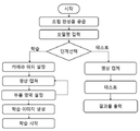
도 3은 본 발명의 일실시 예에 따른 영역 기반의 비젼 검사장치의 작동 순서를 보여주는 작동 순서도이다.
도 3을 참고하면, 우선 검사하고자 하는 조립된 완성품을 안착지그 위의 고정판에 고정 시킨다. 상기 고정판에 조립 완성품이 고정되면 작업자는 조립 완성품의 모델명을 입력한 후 학습 단계와 테스트 단계를 선택한다.
작업자가 학습 단계를 선택하면 조립 완성품의 5면에 대한 Z 스테이지, XZ 스테이지 위치 설정을 수행한다.
작업자가 Z 스테이지, XZ 스테이지 위치 설정 작업이 완료되면, 조립 완성품의 영상을 캡쳐한다. 캡쳐한 영상에 대하여 부품의 누락 여부를 검사할 부품에 대한 영역을 설정한 후, 설정된 영역에 대한 학습 데이터를 생성한다.
완성 조립품에 대한 5면에 대하여 부품의 영역에 대한 학습데이터가 생성되면, 학습을 수행한다.
한편, 도면 3에서 작업자가 단계 선택에서 테스트를 선택하게 되면 검사할 완성 조립품에 대한 5면의 영상을 캡쳐한다.
상기 캡쳐된 영상에 대하여 부품의 누락 테스트가 시행된다. 테스트가 완료되면 결과물로 검사한 조립완성품의 이미지와 검사결과를 그림으로 나타낸다.
도 4는 본 발명의 일실시 예에 따른 영역 기반의 비젼 검사장치의 검사결과를 나타낸다.
상기 도면에서 초록색으로 사각 영역은 부품이 부착됨을 나타내고, 붉은색 사각 영역은 부품이 누락됨을 나타낸다.1 shows a configuration diagram of a region-based vision inspection apparatus according to an embodiment of the present invention.
2 is a view showing various types of fixed plates in a region-based vision inspection apparatus according to an embodiment of the present invention.
Referring to Figure 2, the fixing plate has two holes, which are fixed on the seating jig so that the rotating plate rotates, so that the fixing plate does not shake. In addition, the shape of the top plate of the fixing plate is manufactured in a form that the assembled finished product can be easily fixed.
3 is an operation flowchart showing an operation sequence of a region-based vision inspection apparatus according to an embodiment of the present invention.
Referring to FIG. 3, first, the assembled finished product to be inspected is fixed to the fixing plate on the seating jig. When the assembled finished product is fixed to the fixed plate, the operator enters the model name of the assembled finished product and selects a learning step and a test step.
When the operator selects the learning step, the Z stage and the XZ stage position are set on the 5 sides of the finished assembly.
When the operator completes the Z-stage and XZ-stage positioning operation, an image of the finished assembly is captured. After setting the area for the part to be checked for missing parts in the captured image, learning data for the set area is generated.
When the learning data for the area of the part is generated for the five sides of the finished assembly, learning is performed.
On the other hand, when the operator selects the test in the step selection in Figure 3 captures the image of the five sides of the finished assembly to be inspected.
A missing part test is performed on the captured image. When the test is completed, the image of the assembled product inspected with the result and the inspection result are shown as pictures.
4 shows inspection results of a region-based vision inspection apparatus according to an embodiment of the present invention.
In the figure, the green area indicates that the part is attached, and the red area indicates that the part is missing.
이하, 본 발명의 실시 예들은 첨부된 도면을 참조하여 설명하도록 한다. 다만, 이하의 실시 예들은 본 발명의 이해를 돕기 위해 제공되는 것이며, 본 발명의 범위가 이하의 실시 예들에 한정 되는 것은 아니다. 또한 이하의 실시 예들은 당 업계에서 평균적인 지식을 가진 자에게 본 발명을 보다 완전하게 설명하기 위해 제공되는 것으로, 불필요하게 본 발명의 기술 적인 요지를 흐릴 수 있다고 판단되는 공지의 구성에 대해서는 상세한 기술을 생략하기로 하며, 설명의 편의를 위해 도면에 도시된 각 구성들은 다소 과장되어 도시될 수 있다.Hereinafter, embodiments of the present invention will be described with reference to the accompanying drawings. However, the following embodiments are provided to help understanding of the present invention, and the scope of the present invention is not limited to the following embodiments. In addition, the following embodiments are provided to more fully describe the present invention to those of ordinary skill in the art, and detailed descriptions of well-known configurations determined to unnecessarily obscure the technical gist of the present invention Each component illustrated in the drawings may be exaggerated for convenience of description.
도 1은 본 발명의 일실시 예에 따른 영역 기반의 비젼 검사장치를 보여주는 정면도이다. 도1을 참고하면, 본 발명의 일실시 예에 따른 영역 기반의 비젼 검사장치(1)는 고정판(10), 안착지그(20), 회전 스테이지(30), Z 스테이지(40), XZ 스테이지(50, 51), 조명 장치(60,61,62), 스테이지 컨트롤러(80), 영상 처리부(90), 비젼 검사 모니터가(100)를 포함 할 수 있다.1 is a front view showing a region-based vision inspection apparatus according to an embodiment of the present invention. Referring to Figure 1, the region-based vision inspection apparatus 1 according to an embodiment of the present invention is fixed plate 10, seating jig 20, rotating
안착지그(20)는 바닥 면에 소정의 높이로 설치된 플레이트(plate) 형태로 형성 될 수 있다. 안착지그(20)는 고정판과 회전스테이지 사이에 있으며, 회전판이 회전할 때 고정판은 고정판의 위치가 변경 되지 않도록 고정시킨다.고정판(10)은 다양한 형태의 조립 완성품이 안착지그(20) 위에 고정 될 수 있도록 한다. The seating jig 20 may be formed in the form of a plate installed at a predetermined height on the bottom surface. The seating jig 20 is located between the fixing plate and the rotating stage, and when the rotating plate rotates, the fixing plate is fixed so that the position of the fixing plate is not changed. The fixing plate 10 is to be fixed to the assembly jig 20 various assembly finished products Make it possible.
회전 스테이지(30)는 조립된 완성품의 앞면과 뒷면의 영상을 획득하기 위해 고정판을 회전시킨다.The rotating
Z 스테이지(40)는 조립된 완성품의 윗면의 영상을 획득하기 위해 Z 방향으로 이동 가능하다.The
XZ 스테이지(50, 51)는 조립된 완성품의 앞뒷면과 좌우면의 영상을 획득하기 위해 Z방향과 X 방향으로 이동 가능하다.The
스테이지 컨트롤러(80)는 조립된 완성품의 영상획득을 위해 회전 스테이지(30), Z 스테이지(40), XZ 스테이지(50, 51)를 제어한다.The
카메라(70, 71, 72)와 스테이지 컨트롤러(80)는 각 조립 완성품의 특정 영역 이미지 학습과 판별을 위한 영상을 캡쳐한다. 스테이지 컨트롤러(80)는 각 조립 완성품에 따라 선명한 영상을 획득하기 위해 미리 설정된 위치로 카메라를 움직이게 한다. The
조명장치(60, 61, 62)는 각 조립 완성품에 따라 선명한 영상을 획득하기 위해 조명을 제공한다.The
영상 처리부(90)는 학습을 위해 캡쳐된 영역의 이미지를 가지고 학습을 처리하며, 부품 누락을 판별하기 위해 캡쳐 된 이미지를 가지고 부품 누락 여부를 판단한다. 학습을 위해서는 Z 스테이지(40), XZ 스테이지(50,51)를 통해 캡쳐된 이미지 위에 학습을 위한 영역을 표시하여 학습 이미지를 획득한다. 획득된 학습 이미지를 이용하여 다양한 형태의 학습 이미지를 만든 후, 이를 이용하여 학습을 수행한다. 조립된 완성품에 대한 이미지를 캡쳐 후, 누락 검출은 학습 시 표시된 영역에 대하여 불량 여부를 판단한다. The
Claims (1)
Priority Applications (1)
| Application Number | Priority Date | Filing Date | Title |
|---|---|---|---|
| KR1020180122914A KR20200046149A (en) | 2018-10-16 | 2018-10-16 | Area-based vision testing device |
Applications Claiming Priority (1)
| Application Number | Priority Date | Filing Date | Title |
|---|---|---|---|
| KR1020180122914A KR20200046149A (en) | 2018-10-16 | 2018-10-16 | Area-based vision testing device |
Publications (1)
| Publication Number | Publication Date |
|---|---|
| KR20200046149A true KR20200046149A (en) | 2020-05-07 |
Family
ID=70733130
Family Applications (1)
| Application Number | Title | Priority Date | Filing Date |
|---|---|---|---|
| KR1020180122914A KR20200046149A (en) | 2018-10-16 | 2018-10-16 | Area-based vision testing device |
Country Status (1)
| Country | Link |
|---|---|
| KR (1) | KR20200046149A (en) |
Cited By (2)
| Publication number | Priority date | Publication date | Assignee | Title |
|---|---|---|---|---|
| KR102563230B1 (en) * | 2022-12-09 | 2023-08-03 | (주)일주지앤에스 | AI Vision Fault Detection System |
| KR102599785B1 (en) * | 2023-02-27 | 2023-11-08 | (주)일주지앤에스 | AI Vision Fault Detection System and Method |
-
2018
- 2018-10-16 KR KR1020180122914A patent/KR20200046149A/en unknown
Cited By (2)
| Publication number | Priority date | Publication date | Assignee | Title |
|---|---|---|---|---|
| KR102563230B1 (en) * | 2022-12-09 | 2023-08-03 | (주)일주지앤에스 | AI Vision Fault Detection System |
| KR102599785B1 (en) * | 2023-02-27 | 2023-11-08 | (주)일주지앤에스 | AI Vision Fault Detection System and Method |
Similar Documents
| Publication | Publication Date | Title |
|---|---|---|
| TW201840991A (en) | Testing device and method for circuit board dispensing | |
| JP2006268050A (en) | Image inspection apparatus, panel inspection method and display panel manufacturing method | |
| TWI484164B (en) | Optical re - inspection system and its detection method | |
| WO2019061608A1 (en) | Panel lighting device, panel lighting test system and test method | |
| CN112730419B (en) | Appearance flaw detection device | |
| TWI495867B (en) | Application of repeated exposure to multiple exposure image blending detection method | |
| KR101802843B1 (en) | Automated Vision Inspection System | |
| US20170053394A1 (en) | Inspection apparatus, inspection method, and article manufacturing method | |
| WO2015014067A1 (en) | Quality detection method, apparatus and device for liquid crystal screen | |
| KR20200046149A (en) | Area-based vision testing device | |
| CN211179500U (en) | Multi-light source optical detection system | |
| WO2020175752A1 (en) | Apparatus for inspecting exterior of home appliance | |
| JP7368141B2 (en) | Wafer appearance inspection device and method | |
| CN106200036B (en) | Lighting detection equipment | |
| CN112730421B (en) | Appearance flaw detection device | |
| JP2007132911A (en) | System for sensing vision and luminance of back light unit | |
| KR20110130572A (en) | Block base inspecting method using the same | |
| TW201522949A (en) | Inspection method for image data | |
| KR20160108662A (en) | The electronic component testing apparatus and testing method | |
| US20230138331A1 (en) | Motion in images used in a visual inspection process | |
| TWI672493B (en) | An automatic optical inspection system and method to obtain mura defect from the panel | |
| KR100478448B1 (en) | Method for inspecting edge of liquid crystal display | |
| JP2002071576A (en) | Visual inspection apparatus and visual inspection method | |
| WO2023119882A1 (en) | Wafer external appearance inspecting device | |
| JP2003177371A (en) | Apparatus and method for inspecting liquid crystal display unit |