KR20200044965A - Driving device and its operation - Google Patents
Driving device and its operation Download PDFInfo
- Publication number
- KR20200044965A KR20200044965A KR1020207010162A KR20207010162A KR20200044965A KR 20200044965 A KR20200044965 A KR 20200044965A KR 1020207010162 A KR1020207010162 A KR 1020207010162A KR 20207010162 A KR20207010162 A KR 20207010162A KR 20200044965 A KR20200044965 A KR 20200044965A
- Authority
- KR
- South Korea
- Prior art keywords
- motor winding
- connection
- motor
- phase connection
- half bridge
- Prior art date
Links
Images


Classifications
-
- H—ELECTRICITY
- H02—GENERATION; CONVERSION OR DISTRIBUTION OF ELECTRIC POWER
- H02P—CONTROL OR REGULATION OF ELECTRIC MOTORS, ELECTRIC GENERATORS OR DYNAMO-ELECTRIC CONVERTERS; CONTROLLING TRANSFORMERS, REACTORS OR CHOKE COILS
- H02P29/00—Arrangements for regulating or controlling electric motors, appropriate for both AC and DC motors
- H02P29/50—Reduction of harmonics
-
- H—ELECTRICITY
- H02—GENERATION; CONVERSION OR DISTRIBUTION OF ELECTRIC POWER
- H02M—APPARATUS FOR CONVERSION BETWEEN AC AND AC, BETWEEN AC AND DC, OR BETWEEN DC AND DC, AND FOR USE WITH MAINS OR SIMILAR POWER SUPPLY SYSTEMS; CONVERSION OF DC OR AC INPUT POWER INTO SURGE OUTPUT POWER; CONTROL OR REGULATION THEREOF
- H02M7/00—Conversion of ac power input into dc power output; Conversion of dc power input into ac power output
- H02M7/42—Conversion of dc power input into ac power output without possibility of reversal
- H02M7/44—Conversion of dc power input into ac power output without possibility of reversal by static converters
- H02M7/48—Conversion of dc power input into ac power output without possibility of reversal by static converters using discharge tubes with control electrode or semiconductor devices with control electrode
- H02M7/53—Conversion of dc power input into ac power output without possibility of reversal by static converters using discharge tubes with control electrode or semiconductor devices with control electrode using devices of a triode or transistor type requiring continuous application of a control signal
- H02M7/537—Conversion of dc power input into ac power output without possibility of reversal by static converters using discharge tubes with control electrode or semiconductor devices with control electrode using devices of a triode or transistor type requiring continuous application of a control signal using semiconductor devices only, e.g. single switched pulse inverters
- H02M7/5387—Conversion of dc power input into ac power output without possibility of reversal by static converters using discharge tubes with control electrode or semiconductor devices with control electrode using devices of a triode or transistor type requiring continuous application of a control signal using semiconductor devices only, e.g. single switched pulse inverters in a bridge configuration
-
- H—ELECTRICITY
- H02—GENERATION; CONVERSION OR DISTRIBUTION OF ELECTRIC POWER
- H02M—APPARATUS FOR CONVERSION BETWEEN AC AND AC, BETWEEN AC AND DC, OR BETWEEN DC AND DC, AND FOR USE WITH MAINS OR SIMILAR POWER SUPPLY SYSTEMS; CONVERSION OF DC OR AC INPUT POWER INTO SURGE OUTPUT POWER; CONTROL OR REGULATION THEREOF
- H02M7/00—Conversion of ac power input into dc power output; Conversion of dc power input into ac power output
- H02M7/42—Conversion of dc power input into ac power output without possibility of reversal
- H02M7/44—Conversion of dc power input into ac power output without possibility of reversal by static converters
- H02M7/48—Conversion of dc power input into ac power output without possibility of reversal by static converters using discharge tubes with control electrode or semiconductor devices with control electrode
- H02M7/53—Conversion of dc power input into ac power output without possibility of reversal by static converters using discharge tubes with control electrode or semiconductor devices with control electrode using devices of a triode or transistor type requiring continuous application of a control signal
- H02M7/537—Conversion of dc power input into ac power output without possibility of reversal by static converters using discharge tubes with control electrode or semiconductor devices with control electrode using devices of a triode or transistor type requiring continuous application of a control signal using semiconductor devices only, e.g. single switched pulse inverters
- H02M7/539—Conversion of dc power input into ac power output without possibility of reversal by static converters using discharge tubes with control electrode or semiconductor devices with control electrode using devices of a triode or transistor type requiring continuous application of a control signal using semiconductor devices only, e.g. single switched pulse inverters with automatic control of output wave form or frequency
-
- B—PERFORMING OPERATIONS; TRANSPORTING
- B63—SHIPS OR OTHER WATERBORNE VESSELS; RELATED EQUIPMENT
- B63G—OFFENSIVE OR DEFENSIVE ARRANGEMENTS ON VESSELS; MINE-LAYING; MINE-SWEEPING; SUBMARINES; AIRCRAFT CARRIERS
- B63G8/00—Underwater vessels, e.g. submarines; Equipment specially adapted therefor
- B63G8/08—Propulsion
-
- B—PERFORMING OPERATIONS; TRANSPORTING
- B63—SHIPS OR OTHER WATERBORNE VESSELS; RELATED EQUIPMENT
- B63H—MARINE PROPULSION OR STEERING
- B63H23/00—Transmitting power from propulsion power plant to propulsive elements
- B63H23/22—Transmitting power from propulsion power plant to propulsive elements with non-mechanical gearing
- B63H23/24—Transmitting power from propulsion power plant to propulsive elements with non-mechanical gearing electric
-
- H—ELECTRICITY
- H02—GENERATION; CONVERSION OR DISTRIBUTION OF ELECTRIC POWER
- H02P—CONTROL OR REGULATION OF ELECTRIC MOTORS, ELECTRIC GENERATORS OR DYNAMO-ELECTRIC CONVERTERS; CONTROLLING TRANSFORMERS, REACTORS OR CHOKE COILS
- H02P27/00—Arrangements or methods for the control of AC motors characterised by the kind of supply voltage
- H02P27/04—Arrangements or methods for the control of AC motors characterised by the kind of supply voltage using variable-frequency supply voltage, e.g. inverter or converter supply voltage
- H02P27/06—Arrangements or methods for the control of AC motors characterised by the kind of supply voltage using variable-frequency supply voltage, e.g. inverter or converter supply voltage using dc to ac converters or inverters
- H02P27/08—Arrangements or methods for the control of AC motors characterised by the kind of supply voltage using variable-frequency supply voltage, e.g. inverter or converter supply voltage using dc to ac converters or inverters with pulse width modulation
Abstract
본 발명은, 제1 상 접속부(21)를 갖는 제1 하프 브리지(11), 제2 상 접속부(22)를 갖는 제2 하프 브리지(12), 제3 상 접속부(23)를 갖는 제3 하프 브리지(13) 및 제4 상 접속부(24)를 갖는 제4 하프 브리지(14)를 갖는 구동 장치(1)에 관한 것이며, 여기서 제1 상 접속부(21)는 제1 모터 권선 측 접속부(41)를 갖는 제1 전류 보상 인덕터(31)에 의해 제2 상 접속부(22)와 연결되고, 여기서 제3 상 접속부(23)는 제2 모터 권선 측 접속부(42)를 갖는 제2 전류 보상 인덕터(32)에 의해 제4 상 접속부(24)와 연결된다. 복수의 인버터 모듈들(60, 61, 62)을 갖는 구동 장치를 작동시키는 방법에 따르면, 여기서 복수의 인버터 모듈들(60, 61, 62)은 각각 복수의 하프 브리지들(11, 12, 13, 14, 15, 16, 17, 18)을 갖고, 하프 브리지들(11, 12, 13, 14, 15, 16, 17, 18)은 반파 내에서 오프셋 방식으로 구동된다.The present invention includes a first half bridge 11 having a first phase connection 21, a second half bridge 12 having a second phase connection 22, and a third half having a third phase connection 23. It relates to a drive device (1) having a fourth half bridge (14) having a bridge (13) and a fourth phase connection (24), wherein the first phase connection (21) is the first motor winding side connection (41) Is connected to the second phase connection 22 by a first current compensation inductor 31, wherein the third phase connection 23 is a second current compensation inductor 32 having a second motor winding side connection 42 ) Is connected to the fourth phase connecting portion 24. According to a method of operating a drive device having a plurality of inverter modules (60, 61, 62), wherein the plurality of inverter modules (60, 61, 62) each of the plurality of half bridges (11, 12, 13, 14, 15, 16, 17, 18), and the half bridges 11, 12, 13, 14, 15, 16, 17, 18 are driven in an offset manner within a half wave.

Description
본 발명은, 특히 배 또는 잠수함과 같은 선박에서의 구동 장치 및 그 작동에 관한 것이다.The present invention relates, in particular, to a driving device and its operation in a ship, such as a ship or submarine.
구동 장치는, 예를 들어, EP 2 683 605 B1호 또는 EP 0 178 446 B1호로부터 알려져 있다.The driving device is known, for example, from
본 발명의 과제는 그러한 구동 장치를 개선시키는 것이다.The object of the present invention is to improve such a drive device.
이 과제를 달성하는 수단은 청구항 제1항에 따른 구동 장치에서 또는 청구항 제9항에 따른 방법에서 획득된다. 실시예들은 특히, 청구항 제2항 내지 청구항 제8항에 따라 또는, 청구항 제10항 또는 청구항 제11항에 따라 획득된다.Means for achieving this task are obtained in the drive device according to
구동 장치는 제1 상 접속부(phase connection)를 갖는 제1 하프 브리지(half-bridge), 제2 상 접속부를 갖는 제2 하프 브리지, 제3 상 접속부를 갖는 제3 하프 브리지 및 제4 상 접속부를 갖는 제4 하프 브리지를 가지며, 여기서 제1 상 접속부는 제1 모터 권선 측 접속부를 갖는 제1 전류 보상 인덕터(current-compensated inductor)를 통해 제2 상 접속부와 연결되고, 여기서 제3 상 접속부는 제2 모터 권선 측 접속부를 갖는 제2 전류 보상 인덕터를 통해 제4 상 접속부와 연결된다.The driving device includes a first half-bridge having a first phase connection, a second half-bridge having a second phase connection, a third half-bridge and a fourth phase connection having a third phase connection Having a fourth half bridge, wherein the first phase connection is connected to the second phase connection through a first current-compensated inductor having a first motor winding side connection, where the third phase connection is 2 It is connected to the fourth phase connection through a second current compensation inductor having a motor winding side connection.
권선 섹션에 대한 복수의 반도체 브리지들에 의해 그리고 상간 인덕터들(interphase inductors)(전류 보상 인덕터)의 사용에 의해서는 그러한 방식으로 에너지를 공급받는 전기 기계에 의해 보다 낮은 소음 발생을 가져오는 것이 가능하게 된다.It is possible to bring about lower noise generation by means of a plurality of semiconductor bridges to the winding section and by the use of interphase inductors (current compensating inductors) by an electric machine energized in this way. do.
구동 장치는, 예를 들어, 잠수함에서 사용된다. 잠수함 추진 구동 시스템은, 예를 들어, 영구 자석 여자 회전자와; 복수의 권선 섹션들을 가지는 고정자 권선이 배열된 고정자;를 갖는 전기 기계를 포함하며, 여기서 권선 섹션들 각각에 대해 권선 섹션에 전류를 급전하기 위한 개별적인 컨버터가 각각 존재하고, 여기서 권선 섹션들에 급전하기 위한 컨버터들은 전기 기계의 내부에 배열된다. 하나의 과제는, 예컨대, 효율을 증가시키는 것 그리고/또는 인버터의 전류 고조파들에 의해 야기되는 소음 방출을 감소시키는 것이다. 잠수함 추진 구동은 효율 및 가능한 적은 소음 방출의 면에서 엄격한 요구사항들을 적용받는다. 모터 권선들의 권선 섹션들의 개수를 전환함으로써 엄격한 요구사항들이 충족될 수 있다. 모터는 2개의, 예컨대 동일한 권선 시스템을 갖는다. 각각의 권선 시스템은, 예컨대, 12개의 권선 섹션 및 6개의 인버터 모듈을 가지며, 여기서 각각의 인버터 모듈은 2개의 권선(권선 섹션)에 급전할 수 있다. 더 낮은 부분 부하 범위에서 모터의 효율을 증가시키기 위해, 특정 회전 속도 미만에서 각각의 시스템의, 인버터와 연관된 각각 2개의 권선 섹션의 직렬 접속에 의해 유도 모터 전압이 증가된다. 이 경우에, 인버터들은 절반이 비활성화된다. 모터 회전 속도가 특정 값을 초과하면, 직렬 접속이 해제되고 인버터들이 전체적으로 활성화된다. 권선들 각각은 개별적인 인버터(H-브리지)로부터 다시 급전된다. 따라서 6-권선 섹션 모드와 12-권선 섹션 모드에서의 모터 회전 속도 범위가 구별된다. 특히 더 낮은 회전 속도 범위(2개의 모터 권선들의 직렬 접속으로 구성된 6-권선 섹션 모드)에서 소음 방출의 면에서 엄격한 제한 값들이 적용되므로, 인버터들의 클로킹 주파수에 의해 야기되는 전류 고조파를 감소시키기 위해 높은 인덕턴스를 갖는 부가의 인덕터들이 직렬 회로에 도입된다. 인덕터들의 선택 시에, 인버터 모듈들을 가능한 한 콤팩트하게 유지하기 위해 전류 전달 용량과 전체 체적 사이의 가능한 최상의 절충안이 선택된다. 인버터 모듈들의 일 실시예에서, 이러한 인덕터들 및 그들의 최대 전류 전달 용량은 6-권선 섹션 모드와 12-권선 섹션 모드 사이의 전환점을 정의한다. 권선 섹션의 전환은 커플링 콘택터(coupling contactor)에 의해 수행된다. 전환 이전에, 한편으로는 스위칭 부하, 따라서 커플링 콘택터의 전체 체적을 최소화하기 위해 그리고 다른 한편으로, 스위칭 과정 동안 전기 아크의 발생의 가능성을 최소화하기 위해 권선 섹션 전류가 x A로 감소된다. 변경된 인버터 개념은 또한 효율 및 소음 방출에 대한 엄격한 요구사항들을 충족시키고, 언급한 기준들을 다른 인버터 개념에 비해 개선시킨다. 변경된 인버터 개념에 의해, 더 엄격한 소음 제한들이 적용되는 회전 속도 범위를 상대적으로 높은 회전 속도들로 확장하는 것이 가능하다. 이 경우, 전환점에서 커플링 콘택터 및 전류 감소를 없애는 것이 가능하다. 또한, 부분 부하 범위에서 고조파를 감소시키기 위해, 2개의 모터 권선으로 구성된 직렬 접속에 부가의 인덕터들을 도입할 필요가 없다. 모터에서 생성되는 소음 방출의 레벨은 클로킹 주파수에 의해 생성되는 리플 전류의 레벨에 주로 의존한다. 클로킹 주파수가 높을수록, 최대 리플 전류가 낮아지고 이에 수반하여 기계적 모터 요소들의 여자(excitation)도 낮아진다. 스위칭 손실 및 전도 손실에 의해 영향을 받는 인버터의 효율을 무시하지 않으면서 동시에 모터 권선에서의 클로킹 주파수를 증가시키는 방법들이 발견되면 유리하다.The drive device is used, for example, in submarines. The submarine propulsion drive system includes, for example, a permanent magnet excitation rotor; A stator having a plurality of winding sections, and an electric machine having a stator arranged therein, wherein for each of the winding sections there is a separate converter for supplying current to the winding section, respectively, wherein the winding sections are fed. The converters for are arranged inside the electric machine. One challenge is, for example, to increase efficiency and / or reduce noise emissions caused by the current harmonics of the inverter. Submarine propulsion drives are subject to stringent requirements in terms of efficiency and as little noise emission as possible. Strict requirements can be met by switching the number of winding sections of the motor windings. The motor has two, for example the same winding system. Each winding system has, for example, 12 winding sections and 6 inverter modules, where each inverter module can feed 2 windings (winding section). In order to increase the efficiency of the motor in the lower partial load range, the induction motor voltage is increased by a series connection of each of the two winding sections associated with the inverter of each system, below a certain rotational speed. In this case, the inverters are half inactive. When the motor rotation speed exceeds a certain value, the series connection is disconnected and the inverters are activated as a whole. Each of the windings is fed back from a separate inverter (H-bridge). Therefore, the range of the motor rotation speed in the 6-winding section mode and the 12-winding section mode is distinguished. Strict limiting values are applied in terms of noise emission, especially in the lower rotational speed range (6-winding section mode consisting of a series connection of two motor windings), so high to reduce the current harmonics caused by the clocking frequency of the inverters Additional inductors with inductance are introduced into the series circuit. In selecting the inductors, the best possible compromise between current carrying capacity and total volume is selected to keep the inverter modules as compact as possible. In one embodiment of the inverter modules, these inductors and their maximum current carrying capacity define the turning point between the 6-winding section mode and the 12-winding section mode. The conversion of the winding section is performed by a coupling contactor. Before switching, the winding section current is reduced to x A in order to minimize, on the one hand, the overall volume of the switching load and thus the coupling contactor and, on the other hand, to minimize the possibility of the occurrence of an electric arc during the switching process. The modified inverter concept also meets the strict requirements for efficiency and noise emissions, and improves the criteria mentioned compared to other inverter concepts. By means of a modified inverter concept, it is possible to extend the range of rotational speeds to which the stricter noise limits are applied to relatively high rotational speeds. In this case, it is possible to eliminate the coupling contactor and current reduction at the turning point. Also, in order to reduce harmonics in the partial load range, there is no need to introduce additional inductors in a series connection consisting of two motor windings. The level of noise emission produced by the motor mainly depends on the level of ripple current generated by the clocking frequency. The higher the clocking frequency, the lower the maximum ripple current and consequently the lower the excitation of the mechanical motor elements. It is advantageous if methods are found to increase the clocking frequency in the motor windings at the same time without neglecting the efficiency of the inverter affected by the switching losses and conduction losses.
구동 장치의 일 구성에서, 상기 구동 장치는 모터의 제1 모터 권선을 가지며, 여기서 제1 모터 권선은 제1 모터 권선 단부를 갖고 제2 모터 권선 단부를 갖는다. 모터는, 예를 들어, 동기 기계(synchronous machine) 또는 비동기 기계(asynchronous machine)이다. 동기 기계는 영구 여자형 또는 외부 여자형일 수 있다. 제1 모터 권선 측 접속부는 제1 모터 권선 단부와 연결되고, 제2 모터 권선 측 접속부는 제2 모터 권선 단부와 연결된다.In one configuration of the drive device, the drive device has a first motor winding end of the motor, where the first motor winding has a first motor winding end and a second motor winding end. The motor is, for example, a synchronous machine or an asynchronous machine. The synchronous machine can be permanent excitation or external excitation. The first motor winding side connection is connected to the first motor winding end, and the second motor winding side connection is connected to the second motor winding end.
구동 장치의 일 구성에서, 상기 구동 장치는 제5 상 접속부를 갖는 제5 하프 브리지, 제6 상 접속부를 갖는 제6 하프 브리지, 제7 상 접속부를 갖는 제7 하프 브리지 및 제8 상 접속부를 갖는 제8 하프 브리지를 가지며, 여기서 제5 상 접속부는 제3 모터 권선 측 접속부를 갖는 제3 전류 보상 인덕터를 통해 제6 상 접속부와 연결되고, 여기서 제7 상 접속부는 제4 모터 권선 측 접속부를 갖는 제4 전류 보상 인덕터를 통해 제8 상 접속부와 연결된다.In one configuration of the drive device, the drive device has a fifth half bridge with a fifth phase connection, a sixth half bridge with a six phase connection, a seventh half bridge with a seven phase connection and an eight phase connection Has an eighth half bridge, wherein the fifth phase connection is connected to the sixth phase connection through a third current compensation inductor having a third motor winding side connection, where the seventh phase connection has a fourth motor winding side connection It is connected to the eighth phase connection through a fourth current compensation inductor.
구동 장치의 일 구성에서, 제5 전류 보상 인덕터는 제5 모터 권선 측 접속부를 가지며, 여기서 제6 전류 보상 인덕터는 제6 모터 권선 측 접속부를 갖고, 여기서 제1 모터 권선 측 접속부 및 제3 모터 권선 측 접속부는 전력 컨버터 측에서 제5 전류 보상 인덕터와 연결되며, 여기서 제2 모터 권선 측 접속부 및 제4 모터 권선 측 접속부는 전력 컨버터 측에서 제6 전류 보상 인덕터와 연결된다.In one configuration of the drive device, the fifth current compensation inductor has a fifth motor winding side connection, where the sixth current compensation inductor has a sixth motor winding side connection, where the first motor winding side connection and the third motor winding The side connection is connected to the fifth current compensation inductor at the power converter side, where the second motor winding side connection and the fourth motor winding side connection are connected to the sixth current compensation inductor at the power converter side.
구동 장치의 일 구성에서, 상기 구동 장치는 제1 모터 권선을 가지며, 여기서 제1 모터 권선은 제1 모터 권선 단부를 갖고 제2 모터 권선 단부를 가지며, 여기서 제5 모터 권선 측 접속부는 제1 모터 권선 단부와 연결되고, 제6 모터 권선 측 접속부는 제2 모터 권선 단부와 연결된다.In one configuration of the drive device, the drive device has a first motor winding, wherein the first motor winding has a first motor winding end and a second motor winding end, where the fifth motor winding side connection is a first motor The winding end is connected, and the sixth motor winding side connection is connected to the second motor winding end.
구동 장치의 일 구성에서, 상기 구동 장치는 제1 모터 권선의 제1 모터 권선 단부와의 직접 연결을 위한 제8 하프 브리지, 및 제1 모터 권선의 제2 모터 권선 단부와의 직접 연결을 위한 제9 하프 브리지를 갖는다.In one configuration of the drive device, the drive device comprises: an eighth half bridge for direct connection of the first motor winding with the first motor winding end, and a first connection for direct connection with the second motor winding end of the first motor winding. It has 9 half bridges.
구동 장치의 일 구성에서, 모터는 복수의 모터 권선들을 가지며, 여기서 복수의 모터 권선들은 적어도 하나의 전류 보상 인덕터를 통해 하프 브리지들, 특히 H-브리지들과 각각 연결되며, 여기서 상기 각각의 모터 권선은 제8 하프 브리지 및 제9 하프 브리지와도 연결되고, 여기서 제8 하프 브리지 및 제9 하프 브리지는 특히 인덕터 없이 이러한 각각의 모터 권선과 연결된다.In one configuration of the drive device, the motor has a plurality of motor windings, wherein the plurality of motor windings are each connected to half bridges, in particular H-bridges, via at least one current compensation inductor, wherein each motor winding is Is also connected to the eighth half bridge and the ninth half bridge, where the eighth half bridge and the ninth half bridge are connected to each of these motor windings, especially without an inductor.
구동 장치의 일 구성에서, 2개의 하프 브리지들은 인버터 모듈을 형성한다.In one configuration of the drive device, the two half bridges form an inverter module.
구동 장치를 작동시키는 방법에 따르면, 상기 구동 장치는 복수의 인버터 모듈들을 가지며, 여기서 복수의 인버터 모듈들은 각각 복수의 하프 브리지들을 갖고, 여기서 하프 브리지들은 반파 내에서 오프셋 방식으로 구동된다.According to a method of operating a drive device, the drive device has a plurality of inverter modules, wherein the plurality of inverter modules each have a plurality of half bridges, wherein the half bridges are driven in an offset manner within a half wave.
이러한 방법의 일 구성에서, 모터 권선들을 갖는 전기 기계의 제1 전력 범위에 대해서는, 전류 보상 인덕터를 통해 전기 기계와 연결되는 하프 브리지들이 활성이고, 제1 전력 범위보다 큰 제2 전력 범위에서는, 인덕터 없이 전기 기계와 연결되는 하프 브리지들이 활성이다.In one configuration of this method, for a first power range of an electric machine with motor windings, half bridges connected to the electric machine through a current compensation inductor are active, and in a second power range greater than the first power range, the inductor Half bridges that are connected to the electrical machine without being active are active.
본 발명은 예로서 예시적인 실시예들에 의해 아래에서 더 상세히 설명될 것이다. 동일한 요소들은 여기서 동일한 참조 기호들을 갖는다.
도면들에서:
도 1은 제1 회로를 도시한다;
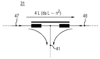
도 2는 상간 인덕터(전류 보상 인덕터)를 도시한다;
도 3은 리플 전류를 도시한다;
도 4는 잠수함을 도시한다;
도 5는 제2 회로를 도시한다.The present invention will be explained in more detail below by way of example embodiments. The same elements have the same reference signs here.
In the drawings:
1 shows a first circuit;
Figure 2 shows the phase-to-phase inductor (current compensation inductor);
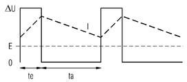
3 shows the ripple current;
4 shows the submarine;
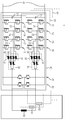
5 shows the second circuit.
도 1에 따른 예시는 제1 상 접속부(21)를 갖는 제1 하프 브리지(11), 제2 상 접속부(22)를 갖는 제2 하프 브리지(12), 제3 상 접속부(23)를 갖는 제3 하프 브리지(13) 및 제4 상 접속부(24)를 갖는 제4 하프 브리지(14)를 가지는 구동 장치(1)를 도시하며, 여기서 제1 상 접속부(21)는 제1 모터 권선 측 접속부(41)를 갖는 제1 전류 보상 인덕터(31)를 통해 제2 상 접속부(22)와 연결되고, 여기서 제3 상 접속부(23)는 제2 모터 권선 측 접속부(42)를 갖는 제2 전류 보상 인덕터(32)를 통해 제4 상 접속부(24)와 연결된다. 또한, 구동 장치(1)는 제5 상 접속부(25)를 갖는 제5 하프 브리지(15), 제6 상 접속부(26)를 갖는 제6 하프 브리지(16), 제7 상 접속부(27)를 갖는 제7 하프 브리지(17) 및 제8 상 접속부(28)를 갖는 제8 하프 브리지(18)를 가지며, 여기서 제5 상 접속부(25)는 제3 모터 권선 측 접속부(43)를 갖는 제3 전류 보상 인덕터(33)를 통해 제6 상 접속부(26)와 연결되고, 여기서 제7 상 접속부(27)는 제4 모터 권선 측 접속부(44)를 갖는 제4 전류 보상 인덕터(34)를 통해 제8 상 접속부(28)와 연결된다. 이 경우, 제5 전류 보상 인덕터(35)는 제5 모터 권선 측 접속부(45)를 가지며, 여기서 제6 전류 보상 인덕터(36)는 제6 모터 권선 측 접속부(46)를 갖고, 여기서 제1 모터 권선 측 접속부(41) 및 제3 모터 권선 측 접속부(43)는 전력 컨버터 측에서 제5 전류 보상 인덕터(35)와 연결되며, 여기서 제2 모터 권선 측 접속부(42) 및 제4 모터 권선 측 접속부(44)는 전력 컨버터 측에서 제6 전류 보상 인덕터(36)와 연결된다. 구동 장치(1)는 제1 모터 권선(50)을 가지며, 여기서 제1 모터 권선(50)은 제1 모터 권선 단부(51)를 갖고 제2 모터 권선 단부(52)를 가지며, 여기서 제5 모터 권선 측 접속부(45)는 제1 모터 권선 단부(51)와 연결되고, 제6 모터 권선 측 접속부(46)는 제2 모터 권선 단부(52)와 연결된다.The example according to FIG. 1 is a
도 1은 클로킹 주파수를 증가시키기 위한 기본 회로를 예시한다. 배터리 전압에 의해 급전되는 2개의 인버터들은 전류 보상 인덕터들에 의해 병렬로 접속되는 각각 2개의 H-브리지들로 구성된다. 인덕터들의 2개의 중심점들은 전류 보상 인덕터에 의해 다시 병렬로 접속된다. 공통적으로 병렬 접속들로부터 결과되는 2개의 인버터들의 중심점들은 모터 권선의 각각 하나의 단부에 접속된다. 각각의 병렬 접속에 의해, 인버터 출력에서 얻어지는 클로킹 주파수는 두 배로 된다. 따라서 모터 권선에서 발생하는 클로킹 주파수는 2개의 이러한 인버터들의 병렬 접속의 결과로서 하나의 개별 반도체 요소의 클로킹 주파수보다 8배 크다. 게다가, 출력 전압의 단계들이 8배 더 정밀하게 선택될 수 있다. 이것은 최대 전류 리플의 계산을 위해 8배 더 작은 전압 익스커션(voltage excursion)이 얻어진다는 것을 의미한다(도 2 참조). 공식(ΔImax = ΔU/(4fTL)(여기서 fT = 클로킹 주파수)에 따르면, 최대 리플 전류는 이에 따라 64배 감소된다. 반도체들 및 인덕터들을 감소시킴으로써 효율을 증가시키는 것이 또한 가능하다. 예를 들어, 절반만, 즉 2개의 H-브리지들만이 사용되고, 그에 대응하여 병렬 접속의 원리에 상응하게, 2개의 전류 보상 인덕터들만이 사용되는 경우, 리플 전류는 16배 감소된다. 따라서, H-브리지들의 개수의 선택과 관련하여, 효율과 최대 전류 리플 간에 절충하는 것이 가능하다(특히 소음 방출이 발견되고 병렬 접속이 그에 상응하게 캐스케이딩된다). H-브리지들에 SiC 반도체들을 사용함으로써 효율의 추가적인 개선이 달성될 수 있다.1 illustrates a basic circuit for increasing the clocking frequency. The two inverters powered by the battery voltage consist of two H-bridges each connected in parallel by current compensation inductors. The two center points of the inductors are again connected in parallel by a current compensation inductor. The center points of the two inverters resulting from the common parallel connections are connected to each one end of the motor winding. With each parallel connection, the clocking frequency obtained at the inverter output is doubled. Therefore, the clocking frequency generated in the motor winding is 8 times greater than the clocking frequency of one individual semiconductor element as a result of the parallel connection of two such inverters. Moreover, the steps of the output voltage can be selected 8 times more precisely. This means that a voltage excursion 8 times smaller is obtained for the calculation of the maximum current ripple (see Fig. 2). According to the formula (ΔI max = ΔU / (4f T L) (where f T = clocking frequency), the maximum ripple current is reduced 64 times accordingly.It is also possible to increase efficiency by reducing semiconductors and inductors. For example, if only half, i.e. only two H-bridges are used, correspondingly to the principle of parallel connection, if only two current compensation inductors are used, the ripple current is reduced 16 times. With regard to the choice of the number of bridges, it is possible to compromise between efficiency and maximum current ripple (especially noise emissions are found and parallel connections are cascaded accordingly) by using SiC semiconductors on the H-bridges Further improvement in efficiency can be achieved.
구동 장치는, 특히, 복수의 모터 권선들을 가지며, 여기서 복수의 모터 권선들은 각각의 경우에 적어도 하나의 전류 보상 인덕터를 통해 하프 브리지들(11, 12, 13, 14, 15, 16, 17, 18), 특히 H-브리지들(86, 87, 88, 89)과 연결되며, 여기서 이러한 각각의 모터 권선은 각각의 제8 하프 브리지 및 제9 하프 브리지와도 연결되고, 여기서 제8 하프 브리지 및 제9 하프 브리지(81, 82)는 특히 인덕터 없이 이러한 각각의 모터 권선(50)과 연결된다.The drive device, in particular, has a plurality of motor windings, where the plurality of motor windings in each case are provided with at least one current compensated inductor half bridges 11, 12, 13, 14, 15, 16, 17, 18 ), In particular H-
도 2에 따른 예시는 상간 인덕터(31)의 전류 분포를 도시한다. 예를 들어, 좌측 및 우측 둘 다에 75의 전류가 제공되고, 이는 지점(41)에서 150A의 전류를 결과한다. 인덕터들의 림들(limbs)에서의 전류들이, 서로 상쇄되는 반대 자기장들을 생성하기 때문에, 코어는 부하 전류에 의해 결과적으로 자화되지 않으며(또는 사실상 자화되지 않으며), 따라서 상기 코어가 상대적으로 작은 치수를 부여받을 수 있다. 인덕터들의 구성에서, 2개의 인버터들 사이의 종방향 인덕턴스(longitudinal inductance)가, 하나의 인버터로부터 다른 인버터로의 횡방향 전류(lateral current)를 적절히 제한하기에 충분히 크다는 점에 유의해야 한다. 인덕터 코어의 포화를 방지하기 위해, 펄스들의 생성에 대한 개입에 의해 이러한 횡방향 전류를 최소로 조절하는 것이 또한 가능하다. 인덕터들의 권선들은 부하 전류를 견딜 수 있도록 하는 방식으로 치수가 정해져야 한다.The example according to FIG. 2 shows the current distribution of the phase-to-
모터 권선을 통한 전류의 절대 값은 인버터들의 각각의 변조도에 의해 결정되며, 여기서 인버터 출력 전류는 인덕터 권선들을 통한 모든 전류들의 합과 항상 동일하다.The absolute value of the current through the motor winding is determined by the respective degree of modulation of the inverters, where the inverter output current is always equal to the sum of all currents through the inductor windings.
도 3에 따른 예시는 리플 전류를 도시한다. 모터 권선을 통한 전류의 절대 값은 인버터들의 각각의 변조도에 의해 결정되며, 여기서 인버터 출력 전류는 인버터 권선들을 통한 모든 전류들의 합과 항상 동일하다.The example according to FIG. 3 shows the ripple current. The absolute value of the current through the motor winding is determined by the respective degree of modulation of the inverters, where the inverter output current is always equal to the sum of all currents through the inverter windings.
도 4에 따른 예시는 잠수함(100)을 도시하며, 여기서 프로펠러(101)는 구동 장치(1)에 의해 구동될 수 있다.The example according to FIG. 4 shows the
도 5에 따른 예시는 도 1의 것에 기초한 구동 장치(1)를 도시한다. 구동 장치(1)는 제1 모터 권선(50)의 제1 모터 권선 단부(51)와의 직접 연결을 위한 제8 하프 브리지, 및 제1 모터 권선(50)의 제2 모터 권선 단부(51)와의 직접 연결을 위한 제9 하프 브리지(82)를 부가적으로 갖는다. 하프 브리지들은 직류 전압 중간 회로(70)에 접속된다. 직류 전압 중간 회로(70)는 중간 회로 커패시터들(71 및 72)을 갖는다. 전기 기계는 복수의 모터 권선들(50, 51, 52 등)을 가지며, 여기서 각각의 모터 권선에 컨버터 모듈(60)이 제공된다. 따라서 구동 장치는 복수의 컨버터 모듈들(60, 61, 62 등)을 갖는다.The example according to FIG. 5 shows a
예를 들어, 50A SiC 모듈들이 2*4개의 하프 브리지에 사용될 수 있다.For example, 50A SiC modules can be used for 2 * 4 half bridges.
하나의 구성에서, 추가적인 인버터 H-브리지가 출력과 병렬로 부가적으로 접속될 수 있다.In one configuration, an additional inverter H-bridge can be additionally connected in parallel with the output.
큰 출력들에서는 경우에 따라 엄격한 소음 요구사항들이 없기 때문에, 출력과 병렬로 추가적인 H-브리지를 부가적으로 접속함으로써 상간 인덕터들의 전체 크기가 작게 유지될 수 있다.At large outputs, in some cases there are no strict noise requirements, so by additionally connecting an additional H-bridge in parallel with the output, the overall size of the phase-to-phase inductors can be kept small.
아래에서 "부스터(booster)"라고도 지칭되는, 부가의 H-브리지는, 예컨대, 프로펠러의 회전 속도의 대략 50%에 상응하는, 정격 전류의 대략 25%까지에서 스위치 오프된다. 따라서 전류 보상 인덕터들을 통해 접속되는 인버터들의 장점들이 모터의 부분 부하 범위에서 사용되는 것이 가능하다. 출력 전류가 정격 전류의 25% 위로 상승하면, 병렬로 접속되는 인버터들은 인버터 커맨드들 또는 제어 커맨드들에 의해 스위치 오프되고, 부스터는 스위치 온된다. 모터의 고전력 범위에서는 경우에 따라 소음 방출에 어떠한 요구사항도 적용되지 않기 때문에, 클로킹 주파수에 의해 생성되는 리플 전류들은 여기서 부수적 역할을 한다. 이것은 최소 필요 개수의 반도체들만을 사용하고 인버터들의 병렬 접속을 위한 인덕터들을 생략하는 것을 가능하게 해준다. 손실이 많은 바로 이러한 부품들의 생략으로 인해, 정격 전류에 이르기까지, 고효율들이 계속 달성될 수 있다. 정격 전류가 25% 한계에 미달하면, 부스터는 스위치 오프되고 인버터들의 병렬 회로는 또다시 스위치 온된다.An additional H-bridge, also referred to hereinafter as a "booster," is switched off to approximately 25% of the rated current, for example, corresponding to approximately 50% of the propeller's rotational speed. Therefore, it is possible that the advantages of the inverters connected through the current compensation inductors are used in the partial load range of the motor. When the output current rises above 25% of the rated current, inverters connected in parallel are switched off by inverter commands or control commands, and the booster is switched on. In the high power range of the motor, the ripple current generated by the clocking frequency plays a secondary role here, because in some cases no requirements apply to noise emission. This makes it possible to use only the minimum required number of semiconductors and omit inductors for parallel connection of inverters. Due to the omission of these very lossy parts, high efficiencies can still be achieved, up to the rated current. When the rated current is below the 25% limit, the booster is switched off and the inverter's parallel circuit is switched on again.
2개의 인버터 부분들(병렬 회로와 부스터)의 이러한 조합에 의해, 효율에 부정적인 영향을 미치는 더 높은 회전 속도 범위에서의 특성들을 감수할 필요가 없으면서 동시에 소음의 회피를 위해 더 낮은 회전 속도 범위에서 적용되는 엄격한 요구사항들을 준수하는 것이 가능하다. 더 낮은 회전 속도 범위에서 활성인 인버터 부분에 대해, 병렬 접속된 H-브리지들의 개수에 걸쳐, 효율 및 소음 방출에 의존하는, 캐스케이딩을 수행하는 것이 가능하다.By this combination of the two inverter parts (parallel circuit and booster), it is not necessary to accept the characteristics in the higher rotational speed range which negatively affects the efficiency, but at the same time it is applied in the lower rotational speed range to avoid noise. It is possible to comply with the stringent requirements. It is possible to perform cascading, which depends on efficiency and noise emissions, over the number of H-bridges connected in parallel, for an inverter part active in a lower rotational speed range.
또한, 이러한 회로에 의해, 모터의 권선 섹션들의 개수를 전체 회전 속도 범위에 걸쳐 일정하게 유지하는 것이 가능하다. 부분 부하 범위에서 효율을 충분히 높게 유지하기 위해 6-권선 섹션 모드와 12-권선 섹션 모드로의 세분이 더 이상 필요하지 않다. 종전의 인버터 개념에 따른 권선 섹션들의 등가의 전환에서와 같이 콘택터들 대신에 반도체들의 사용으로 인해 부스터 모드로의 전환이 원활하게 실행될 수 있다. 스위칭 콘택터들을 생략함으로써, 인버터들을 더 콤팩트하게 구성하는 것이 또한 가능하다. 6-권선 섹션 모드에서 리플 전류를 감소시키기 위해 권선 섹션들의 전환에 필요한 인덕터들이 또한 생략될 수 있다.In addition, with this circuit, it is possible to keep the number of winding sections of the motor constant over the entire rotational speed range. Subdivision into 6-winding section mode and 12-winding section mode is no longer required to keep the efficiency high enough in the partial load range. The transition to the booster mode can be carried out smoothly due to the use of semiconductors instead of contactors, as in the equivalent transition of winding sections according to the conventional inverter concept. By omitting the switching contactors, it is also possible to configure the inverters more compactly. Inductors required for switching of the winding sections to reduce ripple current in 6-winding section mode can also be omitted.
Claims (11)
Applications Claiming Priority (3)
| Application Number | Priority Date | Filing Date | Title |
|---|---|---|---|
| DE102017217948.1 | 2017-10-09 | ||
| DE102017217948.1A DE102017217948A1 (en) | 2017-10-09 | 2017-10-09 | Drive device or its operation |
| PCT/EP2018/076762 WO2019072634A1 (en) | 2017-10-09 | 2018-10-02 | Drive device and operation thereof |
Publications (2)
| Publication Number | Publication Date |
|---|---|
| KR20200044965A true KR20200044965A (en) | 2020-04-29 |
| KR102439088B1 KR102439088B1 (en) | 2022-09-02 |
Family
ID=63840808
Family Applications (1)
| Application Number | Title | Priority Date | Filing Date |
|---|---|---|---|
| KR1020207010162A KR102439088B1 (en) | 2017-10-09 | 2018-10-02 | Drive device and its operation |
Country Status (4)
| Country | Link |
|---|---|
| EP (1) | EP3652852B1 (en) |
| KR (1) | KR102439088B1 (en) |
| DE (1) | DE102017217948A1 (en) |
| WO (1) | WO2019072634A1 (en) |
Families Citing this family (4)
| Publication number | Priority date | Publication date | Assignee | Title |
|---|---|---|---|---|
| DE102020200872A1 (en) | 2020-01-24 | 2021-07-29 | Schmidhauser Ag | Converter, charging station and vehicle |
| DE102020209302A1 (en) * | 2020-07-23 | 2022-01-27 | Siemens Energy Global GmbH & Co. KG | Operating a drive device |
| EP4092895A1 (en) | 2021-05-18 | 2022-11-23 | Siemens Energy Global GmbH & Co. KG | Method for operating a dc converter for supplying an electrolysis device with electrical operating energy |
| CN114248898A (en) * | 2021-12-27 | 2022-03-29 | 中国船舶重工集团公司第七0五研究所 | Dual-redundancy propulsion device and underwater vehicle |
Citations (1)
| Publication number | Priority date | Publication date | Assignee | Title |
|---|---|---|---|---|
| KR20140119164A (en) * | 2012-01-30 | 2014-10-08 | 지멘스 악티엔게젤샤프트 | Elective control of an alternating current motor or direct current motor |
Family Cites Families (5)
| Publication number | Priority date | Publication date | Assignee | Title |
|---|---|---|---|---|
| DE3433886A1 (en) | 1984-09-14 | 1986-03-27 | Siemens AG, 1000 Berlin und 8000 München | CONTROL DEVICE FOR A DC SEMICONDUCTOR CONTROLLER |
| US6545450B1 (en) * | 1999-07-02 | 2003-04-08 | Advanced Energy Industries, Inc. | Multiple power converter system using combining transformers |
| US7109681B2 (en) * | 2004-08-25 | 2006-09-19 | Hamilton Sundstrand Corporation | Parallel inverter motor drive with improved waveform and reduced filter requirements |
| DE102011007599A1 (en) | 2011-04-18 | 2012-10-18 | Siemens Aktiengesellschaft | Method of operating a submarine and submarine |
| DE102013220502B4 (en) * | 2013-10-11 | 2015-07-30 | Bayerische Motoren Werke Aktiengesellschaft | Scalable electric drive system |
-
2017
- 2017-10-09 DE DE102017217948.1A patent/DE102017217948A1/en active Pending
-
2018
- 2018-10-02 WO PCT/EP2018/076762 patent/WO2019072634A1/en unknown
- 2018-10-02 KR KR1020207010162A patent/KR102439088B1/en active IP Right Grant
- 2018-10-02 EP EP18785883.2A patent/EP3652852B1/en active Active
Patent Citations (1)
| Publication number | Priority date | Publication date | Assignee | Title |
|---|---|---|---|---|
| KR20140119164A (en) * | 2012-01-30 | 2014-10-08 | 지멘스 악티엔게젤샤프트 | Elective control of an alternating current motor or direct current motor |
Also Published As
| Publication number | Publication date |
|---|---|
| DE102017217948A1 (en) | 2019-04-11 |
| WO2019072634A1 (en) | 2019-04-18 |
| EP3652852A1 (en) | 2020-05-20 |
| EP3652852B1 (en) | 2024-01-10 |
| KR102439088B1 (en) | 2022-09-02 |
Similar Documents
| Publication | Publication Date | Title |
|---|---|---|
| KR102439088B1 (en) | Drive device and its operation | |
| US11817769B2 (en) | Multibridge power converter with multiple outputs | |
| US7446435B2 (en) | Power converter system and method | |
| JP4727882B2 (en) | Converter for converting electrical energy | |
| US9379597B2 (en) | System for driving electromagnetic appliance and motor driven vehicle | |
| US20140239876A1 (en) | Electric drive with reconfigurable winding | |
| Nallamekala et al. | A fault-tolerant dual three-level inverter configuration for multipole induction motor drive with reduced torque ripple | |
| US8072190B2 (en) | Permanent magnet generator control | |
| EP2290802A1 (en) | Regenerative switched reluctance motor driving system | |
| CN103946059A (en) | Power converter based on h-bridges | |
| US20150229252A1 (en) | Power conversion system and control method thereof | |
| JP7394230B2 (en) | Energy storage module using XRAM current booster | |
| Reddy et al. | Performance enhancement of PPMIM drives by using three 3-Phase four-leg inverters | |
| RU2529306C1 (en) | Electromechanical transmission | |
| Cheng et al. | Integrated drive converter of SDS-SRM with isolation and nonisolation charging capabilities for electric vehicle | |
| KR101654755B1 (en) | Elective control of an alternating current motor or direct current motor | |
| Kumar et al. | DTC of open-end winding induction motor drive using space vector modulation with reduced switching frequency | |
| US10608555B2 (en) | Inverter circuit comprising a circuit arrangement for regenerative damping of electrical oscillations, and method for regenerative damping of electrical oscillations | |
| Wang et al. | Space vector modulation based on lookup table for a dual-inverter-fed open-end winding PMSM drive | |
| JPH0767310B2 (en) | AC motor power supply system | |
| WO2018207719A1 (en) | Variable speed motor device | |
| EP2602926A1 (en) | An electronic power converter | |
| KR20200088549A (en) | A Direct Torque Control Method of Switched Reluctance Motor | |
| JPH09182394A (en) | Ac motor feeding system | |
| KR102388546B1 (en) | Output reactorless modular inverter circuit for driving linear motor |
Legal Events
| Date | Code | Title | Description |
|---|---|---|---|
| E902 | Notification of reason for refusal | ||
| E701 | Decision to grant or registration of patent right | ||
| GRNT | Written decision to grant |