KR20200044043A - Control system for retrograde drill medical devices - Google Patents
Control system for retrograde drill medical devices Download PDFInfo
- Publication number
- KR20200044043A KR20200044043A KR1020207007957A KR20207007957A KR20200044043A KR 20200044043 A KR20200044043 A KR 20200044043A KR 1020207007957 A KR1020207007957 A KR 1020207007957A KR 20207007957 A KR20207007957 A KR 20207007957A KR 20200044043 A KR20200044043 A KR 20200044043A
- Authority
- KR
- South Korea
- Prior art keywords
- blade
- cam
- inner shaft
- longitudinal axis
- elongated body
- Prior art date
Links
Images


Classifications
-
- A—HUMAN NECESSITIES
- A61—MEDICAL OR VETERINARY SCIENCE; HYGIENE
- A61B—DIAGNOSIS; SURGERY; IDENTIFICATION
- A61B17/00—Surgical instruments, devices or methods, e.g. tourniquets
- A61B17/16—Bone cutting, breaking or removal means other than saws, e.g. Osteoclasts; Drills or chisels for bones; Trepans
- A61B17/1613—Component parts
- A61B17/1626—Control means; Display units
-
- A—HUMAN NECESSITIES
- A61—MEDICAL OR VETERINARY SCIENCE; HYGIENE
- A61B—DIAGNOSIS; SURGERY; IDENTIFICATION
- A61B17/00—Surgical instruments, devices or methods, e.g. tourniquets
- A61B17/16—Bone cutting, breaking or removal means other than saws, e.g. Osteoclasts; Drills or chisels for bones; Trepans
- A61B17/1613—Component parts
- A61B17/1615—Drill bits, i.e. rotating tools extending from a handpiece to contact the worked material
- A61B17/1617—Drill bits, i.e. rotating tools extending from a handpiece to contact the worked material with mobile or detachable parts
-
- A—HUMAN NECESSITIES
- A61—MEDICAL OR VETERINARY SCIENCE; HYGIENE
- A61B—DIAGNOSIS; SURGERY; IDENTIFICATION
- A61B17/00—Surgical instruments, devices or methods, e.g. tourniquets
- A61B17/16—Bone cutting, breaking or removal means other than saws, e.g. Osteoclasts; Drills or chisels for bones; Trepans
- A61B17/1613—Component parts
- A61B17/162—Chucks or tool parts which are to be held in a chuck
-
- A—HUMAN NECESSITIES
- A61—MEDICAL OR VETERINARY SCIENCE; HYGIENE
- A61B—DIAGNOSIS; SURGERY; IDENTIFICATION
- A61B17/00—Surgical instruments, devices or methods, e.g. tourniquets
- A61B17/16—Bone cutting, breaking or removal means other than saws, e.g. Osteoclasts; Drills or chisels for bones; Trepans
- A61B17/1613—Component parts
- A61B17/1622—Drill handpieces
- A61B17/1624—Drive mechanisms therefor
-
- A—HUMAN NECESSITIES
- A61—MEDICAL OR VETERINARY SCIENCE; HYGIENE
- A61B—DIAGNOSIS; SURGERY; IDENTIFICATION
- A61B17/00—Surgical instruments, devices or methods, e.g. tourniquets
- A61B17/16—Bone cutting, breaking or removal means other than saws, e.g. Osteoclasts; Drills or chisels for bones; Trepans
- A61B17/1613—Component parts
- A61B17/1631—Special drive shafts, e.g. flexible shafts
-
- A—HUMAN NECESSITIES
- A61—MEDICAL OR VETERINARY SCIENCE; HYGIENE
- A61B—DIAGNOSIS; SURGERY; IDENTIFICATION
- A61B17/00—Surgical instruments, devices or methods, e.g. tourniquets
- A61B17/16—Bone cutting, breaking or removal means other than saws, e.g. Osteoclasts; Drills or chisels for bones; Trepans
- A61B17/1662—Bone cutting, breaking or removal means other than saws, e.g. Osteoclasts; Drills or chisels for bones; Trepans for particular parts of the body
- A61B17/1675—Bone cutting, breaking or removal means other than saws, e.g. Osteoclasts; Drills or chisels for bones; Trepans for particular parts of the body for the knee
-
- A—HUMAN NECESSITIES
- A61—MEDICAL OR VETERINARY SCIENCE; HYGIENE
- A61B—DIAGNOSIS; SURGERY; IDENTIFICATION
- A61B17/00—Surgical instruments, devices or methods, e.g. tourniquets
- A61B2017/00367—Details of actuation of instruments, e.g. relations between pushing buttons, or the like, and activation of the tool, working tip, or the like
Abstract
ACL 재건과 같은 수술 중에 구멍 및 역행 소켓을 드릴링하기 위해 사용되도록 구성된 회전식 절단 의료 디바이스가 개시된다. 디바이스는, 디바이스의 종축과 정렬된 제1 위치와 종축에 비평행한 제2 위치 사이에서 이동 가능하여 역행 소켓을 생성하기 위해 사용되는 블레이드를 원위 단부에 포함할 수 있다. 디바이스는 블레이드를 외부 튜브 및 내부 샤프트 양자 모두의 원위 단부에 연결하고 구멍을 드릴링하고 이어서 역행 소켓을 생성하기 위해 제1 및 제2 위치 사이의 블레이드의 이동을 제어하도록 구성된 블레이드 위치 제어 시스템을 포함할 수 있다. 디바이스는 내부 샤프트와 블레이드가 회전하여 소켓을 절단할 수 있게 하면서 블레이드를 제2 위치에 유지하도록 구성된 위치 유지 시스템을 포함할 수 있다.A rotary cutting medical device is disclosed that is configured to be used to drill holes and retrograde sockets during surgery, such as ACL reconstruction. The device can include at its distal end a blade that is movable between a first position aligned with the device's longitudinal axis and a second position that is non-parallel to the longitudinal axis to be used to create a retrograde socket. The device may include a blade position control system configured to connect the blade to the distal ends of both the outer tube and the inner shaft, drill a hole, and then control the movement of the blade between the first and second positions to create a retrograde socket. You can. The device may include a position retention system configured to hold the blade in a second position while allowing the inner shaft and blade to rotate to cut the socket.

Description
본 발명은 관절경 검사(arthroscopy)에 유용한 회전식 절단 디바이스(rotary cutting devices)에 관한 것으로서, 더 구체적으로는, ACL 재건(reconstruction)을 위한 소켓 및 터널의 드릴링을 위한 플립 역행 절단 디바이스(flip retrograde cutting devices)에 관한 것이다.The present invention relates to rotary cutting devices useful for arthroscopy, and more specifically, flip retrograde cutting for drilling of sockets and tunnels for ACL reconstruction. devices).
관절경 수술 중에, 작은 절개부가 관절경 부위 또는 관절을 덮는 피부에 만들어지고, 캐뉼러가 절개부 내에 삽입되어 수술 디바이스가 관절 내에 배치되어 관절경 시각화를 통해 조작되게 하기 위한 경로를 제공한다. 캐뉼러를 통해 삽입된 수술 디바이스는 길고 얇아야 하는데, 이는 캐뉼러의 직경이 일반적으로 절단 도구의 폭을 제한하기 때문에, 조직을 절단하기 위한 디바이스에 제한을 생성한다.During arthroscopic surgery, a small incision is made on the arthroscopic site or skin covering the joint, and a cannula is inserted into the incision to provide a path for the surgical device to be placed in the joint and manipulated through arthroscopic visualization. The surgical device inserted through the cannula must be long and thin, which creates a limitation on the device for cutting tissue, because the diameter of the cannula generally limits the width of the cutting tool.
플립 절단기는 ACL 재건을 위한 소켓 및 터널의 역행 드릴링을 위해 사용되어 왔다. 플립 절단기는, 예를 들어 플립 역행 절단기의 종축에 실질적으로 평행한 적어도 제1 "직선" 위치와, 예를 들어 플립 역행 절단기의 종축에 대한 비평행 위치인 적어도 제2 "플립" 위치 사이에 관절 연결되도록 구성된 블레이드, 바람직하게는 플립 블레이드를 갖는다. 이러한 플립 역행 절단기를 사용하여, 원위 피질의 최소 절개와 감소된 터널 림의 관절내 골편형성(bone fragmentation)을 갖고 역행 기술을 사용하여 수용 부위 소켓이 내부로부터 외부로 생성될 수 있다. 플립 절단기의 블레이드는 소켓과 터널의 역행 드릴링을 가능하게 하기 위해 제1 및 제2 위치 사이에서 수동으로 이동되었다. 플립 절단기의 블레이드를 적소에 유지하고 이동시키기 위한 더 효율적인 시스템이 요구된다.Flip cutters have been used for back drilling in sockets and tunnels for ACL reconstruction. The flip cutter is articulated, for example, between at least a first “straight” position that is substantially parallel to the longitudinal axis of the flip backing cutter, and at least a second “flip” position that is non-parallel to the longitudinal axis of the flip backing cutter, for example. It has a blade configured to be connected, preferably a flip blade. Using this flip backing cutter, the receiving site socket can be created from the inside to the outside using a retrograde technique with minimal incision of the distal cortex and reduced tunnel rim intra-articular fragmentation. The blades of the flip cutter were manually moved between the first and second positions to enable back drilling of the socket and tunnel. What is needed is a more efficient system for holding and moving the blades of a flip cutter in place.
ACL 재건과 같은 수술 중에 구멍 및 역행 소켓을 드릴링하기 위해 사용되도록 구성된 회전식 절단 의료 디바이스가 개시된다. 디바이스는, 디바이스의 종축과 정렬된 제1 위치와 종축에 비평행한 제2 위치 사이에서 이동 가능하여 역행 소켓을 생성하기 위해 사용되는 블레이드를 원위 단부에 포함할 수 있다. 디바이스는, 구멍을 드릴링하고 이어서 역행 소켓을 생성하기 위해, 블레이드가 제1 및 제2 위치 사이에서 이동 가능하도록 내부 샤프트를 블레이드에 연결하는 연결 시스템을 포함할 수 있다. 디바이스는 블레이드를 외부 튜브 및 내부 샤프트 양자 모두의 원위 단부에 연결하고 구멍을 드릴링하고 이어서 역행 소켓을 생성하기 위해 제1 및 제2 위치 사이의 블레이드의 이동을 제어하도록 구성된 블레이드 위치 제어 시스템을 포함할 수 있다. 디바이스는 역행 소켓을 생성하기 위해 블레이드를 제2 위치에 유지하도록 구성된 위치 유지 시스템을 포함할 수 있다. 위치 유지 시스템은 외부 튜브, 내부 샤프트 및 블레이드가 회전하여 소켓을 절단할 수 있게 하면서 블레이드를 제2 위치에 유지시킨다. 위치 유지 시스템은, 블레이드가 뼈를 통한 강한 드릴링 저항에 직면할 때, 블레이드가 종축과 정렬된 제1 위치로 우발적으로 복귀하는 것을 방지한다.A rotary cutting medical device is disclosed that is configured to be used to drill holes and retrograde sockets during surgery, such as ACL reconstruction. The device can include at its distal end a blade that is movable between a first position aligned with the device's longitudinal axis and a second position that is non-parallel to the longitudinal axis to be used to create a retrograde socket. The device can include a connection system that connects the inner shaft to the blade so that the blade is movable between the first and second positions, to drill the hole and then create a retrograde socket. The device may include a blade position control system configured to connect the blade to the distal ends of both the outer tube and the inner shaft, drill a hole, and then control the movement of the blade between the first and second positions to create a retrograde socket. You can. The device can include a position retention system configured to hold the blade in a second position to create a retrograde socket. The positioning system holds the blade in the second position while allowing the outer tube, inner shaft and blade to rotate to cut the socket. The position retention system prevents the blade from accidentally returning to the first position aligned with the longitudinal axis when the blade encounters strong drilling resistance through the bone.
적어도 하나의 실시예에서, 회전식 절단 디바이스는 원위 단부, 근위 단부, 및 종축을 갖는 세장형 본체로부터 형성될 수 있다. 세장형 본체는 외부 튜브 및 외부 튜브에 의해 수용된 내부 샤프트를 또한 포함할 수 있다. 디바이스는 본체의 원위 단부에 블레이드를 포함할 수 있고, 블레이드는 종축과 전반적으로 정렬된 제1 위치로부터 종축과 비평행한 제2 플립 위치로 회전하도록 구성된다. 디바이스는 블레이드를 외부 튜브 및 내부 샤프트 양자 모두의 원위 단부에 연결하는 블레이드 위치 제어 시스템을 포함할 수 있다. 블레이드 위치 제어 시스템은 블레이드가 종축과 전반적으로 정렬된 제1 위치로부터 종축과 비평행한 제2 플립 위치로 이동하게 하는 내부 샤프트를 블레이드에 연결하는 연결 시스템을 포함할 수 있고, 블레이드가 제2 플립 위치에 잠금될 때 구멍의 역행 드릴링을 위해 블레이드의 절단 모서리가 세장형 본체의 근위 단부를 향해 노출된다. 블레이드 위치 제어 시스템은 블레이드를 제1 및 제2 위치로 이동시키기 위해 캠 종동자와 접하고 내부 샤프트와 접하는 캠을 포함할 수 있다. 블레이드 위치 제어 시스템은, 캠을 제2 위치에 유지하여 내부 샤프트가 제2 위치에 유지되게 하여, 이에 의해 구멍의 역행 드릴링을 위해 내부 샤프트와 블레이드를 회전하게 하면서 절단 모서리가 세장형 본체의 근위 단부를 향해 노출되도록 블레이드의 절단 모서리를 적소에 유지하도록 구성된 위치 유지 시스템을 또한 포함할 수 있다.In at least one embodiment, the rotary cutting device can be formed from an elongated body having a distal end, a proximal end, and a longitudinal axis. The elongated body may also include an outer tube and an inner shaft received by the outer tube. The device can include a blade at the distal end of the body, the blade being configured to rotate from a first position generally aligned with the longitudinal axis to a second flip position that is not parallel to the longitudinal axis. The device can include a blade position control system that connects the blades to the distal ends of both the outer tube and the inner shaft. The blade position control system may include a connection system connecting the inner shaft to the blade that causes the blade to move from a first position generally aligned with the longitudinal axis to a second flip position that is non-parallel with the longitudinal axis, and the blade to the second flip position. When locked in, the cutting edge of the blade is exposed towards the proximal end of the elongated body for retrograde drilling of the hole. The blade position control system may include a cam that contacts the cam follower and the inner shaft to move the blade to the first and second positions. The blade position control system keeps the cam in the second position so that the inner shaft remains in the second position, thereby rotating the inner shaft and blade for retrograde drilling of the hole, with the cutting edge proximal end of the elongated body It may also include a position retention system configured to hold the cutting edge of the blade in place to be exposed toward.
위치 유지 시스템은 위치 유지 시스템이 캠으로부터 연장되는 하나 이상의 핀을 포함할 수 있도록 구성될 수 있다. 위치 유지 시스템은 핀이 내부 샤프트의 홈에 존재하는 동안 내부 샤프트가 회전 가능하여, 이에 의해 내부 샤프트의 축방향 운동을 방지하도록 캠으로부터 연장되는 핀을 수용하기 위한 하나 이상의 홈을 내부 샤프트 상에 포함할 수 있다. 위치 유지 시스템은 내부 샤프트 상의 핀, 캠 및 홈 사이의 잠재적인 오정렬을 처리하도록 핀을 수용하기 위한 캠 내의 하나 이상의 슬롯을 포함할 수 있다.The positioning system can be configured such that the positioning system can include one or more pins extending from the cam. The positioning system includes one or more grooves on the inner shaft for receiving the pins extending from the cam so that the inner shaft is rotatable while the pins are in the grooves of the inner shaft, thereby preventing axial movement of the inner shaft can do. The positioning system can include one or more slots in the cam to accommodate the pins to handle potential misalignment between the pins, cams and grooves on the inner shaft.
블레이드 위치 제어 시스템의 캠은 그를 통해 연장되는 내부 샤프트를 수용하도록 구성된 튜브 수용 챔버에 의해 분리된 제1 헤드 부재 및 제2 헤드 부재로부터 형성될 수 있다. 캠 종동자는 캠을 제1 위치에 유지하도록 구성된 제1 위치 리테이너를 포함할 수 있는데, 이는 또한 종축과 전반적으로 정렬된 위치에 블레이드를 유지한다. 캠 종동자는, 내부 샤프트와 블레이드를 회전하게 하면서 구멍의 역행 드릴링을 위해 절단 모서리가 세장형 본체의 근위 단부를 향해 노출되도록 블레이드의 절단 모서리가 위치되어 있는 제2 위치에 캠을 유지하도록 구성된 제2 위치 리테이너를 또한 포함할 수 있다. 제1 위치 리테이너는 캠을 제1 위치에 유지하도록 구성된 오목형 디텐트(detent)를 갖는 비선형 결합면으로부터 형성될 수 있는데, 이는 또한 종축과 전반적으로 정렬된 위치에 블레이드를 유지한다. 제1 및 제2 위치 리테이너 사이의 캠 종동자의 결합면은 세장형 본체의 종축에 대해 비직교할 수 있다. 제2 위치 리테이너는 세장형 본체의 종축에 전반적으로 직교하는 편평면으로부터 형성될 수 있다. 제2 위치 리테이너는 제1 위치 리테이너보다 세장형 본체의 원위 단부에 더 가깝게 위치될 수 있다.The cam of the blade position control system can be formed from a first head member and a second head member separated by a tube receiving chamber configured to receive an inner shaft extending therethrough. The cam follower can include a first position retainer configured to hold the cam in the first position, which also holds the blade in a position generally aligned with the longitudinal axis. The cam follower is configured to hold the cam in a second position where the cutting edge of the blade is positioned such that the cutting edge is exposed toward the proximal end of the elongate body for retrograde drilling of the hole while rotating the inner shaft and blade. It may also include a two-position retainer. The first position retainer can be formed from a nonlinear engaging surface having a concave detent configured to hold the cam in the first position, which also holds the blade in a position generally aligned with the longitudinal axis. The engaging surface of the cam follower between the first and second position retainers may be non-orthogonal to the longitudinal axis of the elongated body. The second position retainer may be formed from a flat surface generally orthogonal to the longitudinal axis of the elongated body. The second position retainer may be located closer to the distal end of the elongated body than the first position retainer.
디바이스는 캠을 적소에 유지하도록 구성된 하우징을 또한 포함할 수 있고, 여기서 하우징은 캠이 우발적으로 변위되는 것을 방지하고 단지 하나의 축 둘레로 캠의 회전을 제한하기 위해 캠을 수용하는 내부 측면을 포함한다. 디바이스는, 캠 종동자를 캠과 접촉하여 유지하도록 캠 종동자를 캠을 향해 편향시키도록 구성되고 내부 샤프트를 세장형 본체의 원위 단부를 향해 편향시키도록 구성된 편향 메커니즘을 또한 포함할 수 있다. 디바이스는 근위 단부에 위치되고 핸드피스 상의 제어부에 의해 제어되는 바와 같이, 내부 샤프트 및 블레이드에 회전 모션을 부여하기 위해 핸드피스와 기계적으로 접하여 내부 샤프트를 배치하도록 구성되는 구동 허브를 포함할 수 있다.The device may also include a housing configured to hold the cam in place, wherein the housing includes an inner side that receives the cam to prevent the cam from being accidentally displaced and to limit the cam's rotation around only one axis. do. The device may also include a deflection mechanism configured to deflect the cam follower towards the cam to maintain the cam follower in contact with the cam and configured to deflect the inner shaft toward the distal end of the elongated body. The device may include a drive hub positioned at the proximal end and configured to place the inner shaft in mechanical contact with the handpiece to impart rotational motion to the inner shaft and blade, as controlled by a control on the handpiece.
적어도 하나의 실시예에서, 내부 샤프트를 블레이드에 연결하는 연결 시스템은, 블레이드를 제2 플립 위치로 회전시키기 위해 블레이드의 회전 운동으로의 내부 샤프트의 선형 운동의 변환을 허용하는 핀 및 슬롯으로부터 형성될 수 있다. 블레이드는 외부 튜브에 관한 내부 샤프트의 선형 운동시에 제2 플립 위치로 회전하고, 핀은 블레이드의 회전을 허용하기 위해 슬롯 내에서 활주한다. 블레이드가 제2 플립 위치에 있을 때, 블레이드는 세장형 본체의 종축에 대해 비평행 위치로 관절 연결된다. 또한, 블레이드가 제2 플립 위치에 있을 때, 구멍의 역행 드릴링을 위해 블레이드의 절단 모서리가 세장형 본체의 근위 단부를 향해 노출된다.In at least one embodiment, a connecting system that connects the inner shaft to the blade is formed from pins and slots that allow conversion of the linear shaft's linear motion to the blade's rotational motion to rotate the blade to a second flip position. You can. The blade rotates in the second flip position during linear motion of the inner shaft relative to the outer tube, and the pin slides within the slot to allow rotation of the blade. When the blade is in the second flip position, the blade is articulated in a non-parallel position with respect to the longitudinal axis of the elongated body. Also, when the blade is in the second flip position, the cutting edge of the blade is exposed towards the proximal end of the elongated body for retrograde drilling of the hole.
디바이스의 장점은, 이에 한정되는 것은 아니지만 외과 의사와 같은 사용자가, 블레이드가 우발적으로 위치로부터 튀어나오지 않고 역행 소켓을 계속 드릴링하기 전에 블레이드가 재배치되는 것을 요구하지 않고, 역행 소켓을 생성하기 위해 핸드피스를 사용할 수 있다는 것이다.The advantage of the device is, but not limited to, a handpiece to create a retrograde socket without requiring the user to reposition the blade before the user continues to drill the retrograde socket without the blade accidentally protruding from the position. Is that you can use
디바이스의 다른 장점은, 위치 유지 시스템이 임의의 측방향 운동을 방지하여, 이에 의해 블레이드가 회전하여 뼈를 절단하는 것을 가능하게 하도록 회전 모션을 가능하게 하면서, 블레이드가 위치로부터 우발적으로 튀어나오는 것을 방지한다는 것이다.Another advantage of the device is that the position retaining system prevents any lateral movement, thereby enabling rotational motion to allow the blade to rotate to cut the bone, while preventing the blade from accidentally popping out of position. Is that
디바이스의 또 다른 장점은, 블레이드 위치 제어 시스템이 세장형 본체의 종축과 전반적으로 정렬된 제1 위치와 블레이드가 종축과 비평행하고 역행 소켓을 생성하도록 위치된 제2 플립 위치 사이에서 블레이드를 이동시킨다는 것이다.Another advantage of the device is that the blade position control system moves the blade between a first position generally aligned with the longitudinal axis of the elongated body and a second flip position where the blade is non-parallel to the longitudinal axis and positioned to create a retrograde socket. .
디바이스의 다른 장점은, 블레이드 제어 시스템이 단일 레버를 통해, 이에 한정되는 것은 아니지만 외과 의사와 같은 사용자에 의해 제어될 수 있다는 것이다.Another advantage of the device is that the blade control system can be controlled by a user, such as, but not limited to, a surgeon through a single lever.
디바이스의 또 다른 장점은 위치 유지 시스템, 외부 허브 및 레버 아암이 회전하지 않고, 오히려, 단지 내부 샤프트만이 회전하고, 적어도 하나의 실시예에서, 단지 내부 샤프트 및 외부 튜브만이 회전하기 때문에, 위치 유지 시스템이 디바이스의 안전을 향상시킨다는 것이다.Another advantage of the device is the position, as the positioning system, the outer hub and lever arm do not rotate, rather, only the inner shaft rotates, and in at least one embodiment, only the inner shaft and outer tube rotate. The maintenance system improves the safety of the device.
이들 및 다른 실시예가 이하에 더 상세히 설명된다.These and other embodiments are described in more detail below.
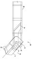
도 1은 회전식 절단 의료 디바이스의 사시도이다.
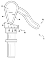
도 2는 도 1의 의료 디바이스의 분해 사시도이다.
도 3은 도 2의 상세 3-3에서 취한 의료 디바이스의 원위 단부의 상세 사시도이다.
도 4는 도 1의 섹션 라인 4-4에서 취한 블레이드의 부분 단면 사시도이다.
도 5는 내부 샤프트의 원위 단부의 부분 사시도이다.
도 6은 도 1의 섹션 라인 6-6에서 취한 의료 디바이스의 원위 단부의 부분 단면도이다.
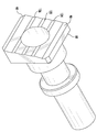
도 7은 도 1의 섹션 라인 7-7에서 취한 의료 디바이스의 근위 단부의 부분 분해 상세 사시도이다.
도 8은 도 1의 섹션 라인 7-7에서 취한 의료 디바이스의 근위 단부의 상세 사시도이다.
도 9는 도 8의 섹션 라인 9-9에서 취한 의료 디바이스의 근위 단부의 단면 사시도이다.
도 10은 도 8의 섹션 라인 9-9에서 취한 의료 디바이스의 근위 단부의 측단면도이다.
도 11은 하우징이 제거되어 있는 상태에서 의료 디바이스의 근위 단부의 측면도이다.
도 12는 캠 종동자가 제거되어 있는 상태에서 의료 디바이스의 근위 단부의 분해 사시도이다.
도 13은 도 11의 섹션 라인 13-13에서 취한, 하우징이 제거되어 있는 상태에서 의료 디바이스의 근위 단부의 측단면도이다.
도 14는 의료 디바이스를 사용하는 방법의 흐름도이다.
도 15는 블레이드가 제1 위치에 위치되어 있는 상태에서 환자의 뼈를 통해 드릴링된 외부 튜브 및 내부 샤프트의 측단면도이다.
도 16은 블레이드가 제2 플립된 위치에 위치되어 있는 상태에서 환자의 뼈를 통해 드릴링된 외부 튜브 및 내부 샤프트의 측단면도이다.
도 17은 블레이드가 제2 플립된 위치에 위치되어 있고 역행 소켓을 드릴링하는 데 사용되는 외부 튜브 및 내부 샤프트의 측단면도이다.
도 18은 제1 위치에서의 블레이드의 상세 측면도이다.
도 19는 제1 및 제2 위치 사이에서 이동하는 블레이드의 상세 측면도이다.
도 20은 제2 위치에서의 블레이드의 상세 측면도이다.
도 21은 제1 위치, 제2 위치에 있고 제1 및 제2 위치 사이에서 이동하는 블레이드의 상세 편집 측면도이다.
도 22는 제1 위치에서의 작동 디바이스를 도시하고 있는 디바이스의 근위 단부의 상세도이다.
도 23은 도 22의 상세도의 측단면도이다.
도 24는 작동 디바이스가 도 22 및 도 23에 도시되어 있는 제1 위치에 있고 캠이 캠 종동자 상의 제1 위치 리테이너와 접촉할 때 디바이스의 원위 단부의 상세 측면도이다.
도 25는 제2 위치에서의 작동 디바이스를 도시하고 있는 디바이스의 근위 단부의 상세도이다.
도 26은 도 25의 상세도의 측단면도이다.
도 27은 작동 디바이스가 도 25 및 도 26에 도시되어 있는 제2 위치에 있고 캠이 캠 종동자 상의 제2 위치 리테이너와 접촉할 때 디바이스의 원위 단부의 상세 측면도이다.
도 28은 캠이 캠 종동자 상의 제3 위치 리테이너와 접촉하고 작동 디바이스가 도 24 및 도 27에 도시되어 있는 제1 및 제2 위치 사이에 위치될 때 블레이드가 약 45도에 있는 디바이스의 원위 단부의 상세 측면도이다.
도 29는 디바이스의 원위 단부에서 블레이드가 약 45도에 있을 때 캠이 캠 종동자 상의 제3 위치 리테이너와 접촉하고 있는 상태에서 캠과 캠 종동자의 상세 측면도이다.
도 30은 제1, 제2, 제3, 제4 및 제5 위치 리테이너를 포함하는 캠 종동자의 다른 실시예의 사시도이다.
도 31은 제1, 제2, 제3, 제4 및 제5 위치 리테이너를 포함하는 도 29에 도시되어 있는 캠 종동자의 다른 실시예의 측면도이다.
도 32는 캠 종동자 상의 제4 위치 리테이너와 접촉하는 캠의 사시도이다.
도 33은 캠 종동자 상의 제4 위치 리테이너와 접촉하는 캠의 측면도이다.
도 34는 캠이 캠 종동자 상의 제4 위치 리테이너와 접촉하고 작동 디바이스가 제1 및 제3 위치 사이에 위치될 때 제4 위치에서 블레이드가 약 30도에 있는 상태에서 디바이스의 원위 단부의 상세 측면도이다.
도 35는 캠 종동자 상의 제5 위치 리테이너와 접촉하는 캠의 측면도이다.
도 36은 캠이 캠 종동자 상의 제5 위치 리테이너와 접촉하고 작동 디바이스가 제2 및 제3 위치 사이에 위치될 때 제5 위치에서 블레이드가 약 60도에 있는 상태에서 디바이스의 원위 단부의 상세 측면도이다.1 is a perspective view of a rotary cutting medical device.
FIG. 2 is an exploded perspective view of the medical device of FIG. 1.
3 is a detailed perspective view of the distal end of the medical device taken in detail 3-3 of FIG. 2;
4 is a partial cross-sectional perspective view of the blade taken in section line 4-4 of FIG. 1;
5 is a partial perspective view of the distal end of the inner shaft.
6 is a partial cross-sectional view of the distal end of the medical device taken at section line 6-6 of FIG. 1.
7 is a partially exploded detail perspective view of the proximal end of the medical device taken in section line 7-7 of FIG. 1;
8 is a detailed perspective view of the proximal end of the medical device taken at section line 7-7 of FIG. 1;
9 is a cross-sectional perspective view of the proximal end of the medical device taken at section line 9-9 of FIG. 8.
10 is a cross-sectional side view of the proximal end of the medical device taken at section line 9-9 of FIG. 8.
11 is a side view of the proximal end of the medical device with the housing removed.
12 is an exploded perspective view of the proximal end of the medical device with the cam follower removed.
FIG. 13 is a cross-sectional side view of the proximal end of the medical device with the housing removed, taken at section line 13-13 of FIG. 11.
14 is a flowchart of a method of using a medical device.
15 is a side cross-sectional view of the outer tube and inner shaft drilled through the patient's bone with the blade in the first position.
16 is a side cross-sectional view of the outer tube and the inner shaft drilled through the patient's bone with the blade positioned in the second flipped position.
17 is a side cross-sectional view of the outer tube and inner shaft where the blade is positioned in the second flipped position and used to drill the retrograde socket.
18 is a detailed side view of the blade in the first position.
19 is a detailed side view of a blade moving between first and second positions.
20 is a detailed side view of the blade in the second position.
21 is a detailed edited side view of a blade in a first position, a second position and moving between the first and second positions.
22 is a detailed view of the proximal end of the device showing the operating device in the first position.
23 is a side cross-sectional view of the detailed view of FIG. 22.
FIG. 24 is a detailed side view of the distal end of the device when the operating device is in the first position shown in FIGS. 22 and 23 and the cam contacts the first position retainer on the cam follower.
25 is a detailed view of the proximal end of the device showing the operating device in the second position.
26 is a side cross-sectional view of the detailed view of FIG. 25.
27 is a detailed side view of the distal end of the device when the operating device is in the second position shown in FIGS. 25 and 26 and the cam contacts the second position retainer on the cam follower.
28 shows the distal end of the device with the blade at about 45 degrees when the cam contacts the third position retainer on the cam follower and the actuating device is positioned between the first and second positions shown in FIGS. 24 and 27. It is a detailed side view.
29 is a detailed side view of the cam and cam follower with the cam in contact with the third position retainer on the cam follower when the blade is at about 45 degrees at the distal end of the device.
30 is a perspective view of another embodiment of a cam follower comprising first, second, third, fourth and fifth position retainers.
31 is a side view of another embodiment of the cam follower shown in FIG. 29 including first, second, third, fourth and fifth position retainers.
32 is a perspective view of a cam in contact with a fourth position retainer on a cam follower.
33 is a side view of the cam in contact with the fourth position retainer on the cam follower.
FIG. 34 is a detailed side view of the distal end of the device with the blade at about 30 degrees in the fourth position when the cam contacts the fourth position retainer on the cam follower and the actuating device is positioned between the first and third positions to be.
35 is a side view of the cam in contact with the fifth position retainer on the cam follower.
Figure 36 is a detailed side view of the distal end of the device with the blade at about 60 degrees in the fifth position when the cam contacts the fifth position retainer on the cam follower and the actuating device is positioned between the second and third positions to be.
도 1 내지 도 36에 도시된 바와 같이, ACL 재건과 같은 수술 중에 구멍 및 역행 소켓을 드릴링하기 위해 사용되도록 구성된 회전식 절단 의료 디바이스(10)가 개시된다. 디바이스(10)는, 디바이스(10)의 종축(18)과 정렬된 제1 위치(16)와 종축(18)에 비평행한 제2 위치(20) 사이에서 이동 가능하여 역행 소켓(32) 및 터널을 생성하기 위해 사용되는 블레이드(12)를 원위 단부(14)에 포함할 수 있다. 디바이스(10)는 도 15 내지 도 27에 도시된 바와 같이, 구멍(24)을 드릴링하고 이어서 역행 소켓(32) 또는 터널을 생성하기 위해, 블레이드(12)가 제1 및 제2 위치(16, 20) 사이에서 이동 가능하도록 내부 샤프트(24)를 블레이드(12)에 연결하는 연결 시스템(22)을 포함할 수 있다. 디바이스(10)는 블레이드(12)를 외부 튜브(28) 및 내부 샤프트(24) 양자 모두의 원위 단부(15, 17)에 연결하고 구멍(30)을 드릴링하고 이어서 역행 소켓(32) 또는 터널을 생성하기 위해 제1 및 제2 위치(16, 20) 사이의 블레이드(12)의 이동을 제어하도록 구성된 블레이드 위치 제어 시스템(26)을 포함할 수 있다. 디바이스(10)는 역행 소켓(32) 또는 터널을 생성하기 위해, 도 16, 도 20 및 도 25 내지 도 27에 도시된 바와 같이, 블레이드(12)를 제2 위치(20)에 유지하도록 구성된, 도 7 및 도 9 내지 도 13에 도시된 바와 같은, 위치 유지 시스템(34)을 포함할 수 있다. 위치 유지 시스템(34)은 내부 샤프트(24)와 블레이드(12)가 회전하여 소켓을 절단할 수 있게 하면서 블레이드(12)를 제2 위치(20)에 유지시킨다. 위치 유지 시스템(34)은, 블레이드(12)가 뼈를 통한 강한 드릴링 저항에 직면할 때, 블레이드(12)가 종축(18)과 정렬된 제1 위치(16)로 우발적으로 복귀하는 것을 방지한다.1 to 36, a rotary amputation
적어도 하나의 실시예에서, 회전식 절단 디바이스(10)는 원위 단부(14), 근위 단부(38), 및 종축(18)을 갖는 세장형 본체(36)로부터 형성될 수 있다. 세장형 본체(36)는 외부 튜브(28) 및 외부 튜브(28)에 의해 수용된 내부 샤프트(24)를 또한 포함할 수 있다. 내부 및 외부 튜브(24, 28)는 이들에 한정되는 것은 아니지만, 17-4 ph 또는 17-7 ph 스테인리스강과 같은 재료로부터 형성될 수 있다. 내부 샤프트(24)는 일반적으로 외부 튜브(28)와 정렬되면서 외부 튜브(28) 내에 피팅되도록 크기 설정될 수 있다.In at least one embodiment, the
디바이스(10)는 본체(36)의 원위 단부(14)에 블레이드(12)를 포함할 수 있다. 블레이드(12)는 종축과 전반적으로 정렬된 제1 위치(16)로부터 종축(18)과 비평행한 제2 플립 위치(20)로 회전하도록 구성될 수 있다. 제1 위치(16)는 약 0도일 수 있다. 적어도 하나의 실시예에서, 제2 플립 위치(20)에 위치된 블레이드(12)는 제1 위치(16)에서 블레이드(12)에 전반적으로 직교하여 위치될 수 있다. 적어도 하나의 실시예에서, 제2 플립 위치(20)에 위치된 블레이드(12)는 제1 위치(16)에서 블레이드(12)에 일반적으로 90도로 위치될 수 있다. 다른 실시예에서, 제2 플립 위치에서의 블레이드(12)는 90도 이외의 각도로 위치될 수 있다.
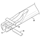
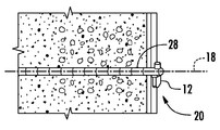
블레이드(12)는 제1 위치(16)에 있을 때, 블레이드(12)가 환자의 뼈에 구멍(30)을 드릴링하는 데 사용되고, 제2 위치(20)에 있을 때, 역행 소켓(32) 또는 터널을 드릴링하는 데 사용되는 것을 가능하게 하는 임의의 적절한 구성을 가질 수 있다. 적어도 하나의 실시예에서, 블레이드(12)는 원위 팁의 선단 에지를 형성하는 절단 모서리(50)를 포함할 수 있다. 선단 에지는 비평행할 수 있고, 세장형 본체(36)의 종축에 대해 비직교할 수 있다. 제2 위치(20)에서, 도 20 및 도 21에 도시된 바와 같이, 절단 모서리(50)는 세장형 본체(36)의 종축에 전반적으로 직교하여 위치될 수 있다.When the
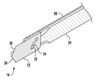
블레이드 위치 제어 시스템(26)은 제1 및 제2 위치(16, 20) 사이에서 블레이드(12)의 위치를 제어하도록 구성될 수 있다. 적어도 하나의 실시예에서, 블레이드 위치 제어 시스템(26)은 블레이드(12)를 외부 튜브(28) 및 내부 샤프트(24) 양자 모두의 원위 단부에 연결할 수 있다. 블레이드 위치 제어 시스템(26)은 블레이드(12)가 종축(18)과 전반적으로 정렬된 제1 위치(16)로부터 종축(18)과 비평행한 제2 플립 위치(20)로 이동하게 하는 내부 샤프트(24)를 블레이드(12)에 연결하는 연결 시스템(22)을 포함할 수 있고, 이에 의해 블레이드(12)가 제2 플립 위치(20)에 잠금될 때 구멍(30)의 역행 드릴링을 위해 블레이드(12)의 절단 모서리(50)가 세장형 본체(36)의 근위 단부(38)를 향해 노출된다. 적어도 하나의 실시예에서, 내부 샤프트(24)를 블레이드(12)에 연결하는 연결 시스템(22)은, 외부 튜브(28)에 관한 내부 샤프트(24)의 선형 운동시에 블레이드(12)를 제2 플립 위치(20)로 회전시키기 위해 블레이드(12)의 회전 운동으로의 내부 샤프트(24)의 선형 운동의 변환을 허용하는 핀(52) 및 슬롯(54)을 포함할 수 있다. 도 4에 도시된 바와 같이, 핀(52)은 슬롯(54) 내에서 활주하여, 핀 또는 다른 적절한 디바이스일 수 있는 피봇 지점(56) 둘레로의 블레이드(12)의 회전을 허용할 수 있다. 적어도 하나의 실시예에서, 피봇 지점(56)은 블레이드(12)가 외부 튜브(28)에 피봇 가능하게 결합되는 지점이다. 블레이드(12)는 외부 튜브(28)의 원위 단부 내에 부분적으로 존재할 수 있고, 블레이드(12)가 제2 위치(20)로 회전되는 것을 가능하게 하도록 구성된 2개의 슬롯(57)을 포함할 수 있다. 이러한 구성은 블레이드가 내부 샤프트(24)의 측방향 운동을 통해 제1 위치(16)로부터 제2 위치(20)로, 또는 그 반대로 이동 가능하게 되는 것을 가능하게 한다. 내부 샤프트(24)가 측방향으로 이동될 때, 블레이드(12)는 세장형 본체(36)의 종축(18)에 대해 비평행한 제2 위치(20)에 관절 연결될 수 있는데, 이 제2 위치에서 블레이드(12)가 제2 플립 위치(20)에 잠금될 때 구멍(30)의 역행 드릴링을 위해 블레이드(12)의 절단 모서리(50)가 세장형 본체(36)의 근위 단부(38)를 향해 노출된다.The blade
블레이드 위치 제어 시스템(26)은 블레이드(12)를 제1 및 제2 위치(16, 20)로 이동시키기 위해 내부 샤프트(24)와 접하는 캠 종동자(60)와 접하는 하나 이상의 캠(58)을 포함할 수 있다. 적어도 하나의 실시예에서, 캠(58)은 그를 통해 연장되는 내부 샤프트(24)를 수용하도록 구성된 튜브 수용 챔버(66)에 의해 분리된 제1 헤드 부재(62) 및 제2 헤드 부재(64)로부터 형성될 수 있다. 내부 샤프트(24)를 스트래들링(straddling)하면, 내부 샤프트(24)는 캠(58)으로부터 연장되는 레버 아암일 수 있지만 이에 한정되는 것은 아닌 작동 디바이스(68)에 의해 캠(58) 상에 배치된 토크에 대한 안정성 및 저항을 제공한다. 블레이드 위치 제어 시스템(26)은 캠(58)을 적소에 유지하도록 구성된 하우징(70)을 포함할 수 있고, 여기서 하우징(70)은 캠(58)이 우발적으로 변위되는 것을 방지하고 단지 하나의 축 둘레로 회전하도록 캠(58)의 회전을 제한하기 위해 캠(58)을 수용하는 내부 측면(72)을 포함할 수 있다. 적어도 하나의 실시예에서, 도 7에 도시된 바와 같이, 하우징(70)은, 서로 대면하고 하우징(70)이 캠(58)의 운동을 제한하여 캠(58)의 외부 측면(80)이 하우징(70)의 제1 및 제2 내부 측면(74, 76)과 전반적으로 정렬된 방향으로 이동하는 상태에서만 캠(58)이 이동할 수 있게 하도록 구성된 캠 수용 캐비티(78)를 부분적으로 형성하는 제1 내부 측면(74) 및 제2 내부 측면(76)을 포함할 수 있다. 특히, 하우징(70)은 도 7에 도시된 바와 같이 작동 디바이스(68)가 하우징(70)으로부터 이격하여 반경방향으로 연장되는 제1 위치(82)와, 작동 디바이스(68)가 외부 튜브(28)와 전반적으로 정렬될 수 있는 도 25 및 도 26에 도시된 바와 같은 제2 위치(84) 사이에서 캠(58)의 운동을 제한한다.The blade
캠(58)은 또한 캠(58)의 과회전을 방지하도록 구성될 수 있다. 특히, 캠(58)은 캠(58)의 과회전을 방지하도록 구성된 제1 측면 에지(96)를 포함할 수 있다. 특히, 캠(58)이 제1 위치(82)에 있을 때 캠(58)의 제1 측면 에지(96)는 하우징(70)의 내부면(71)과 전반적으로 정렬될 수 있다. 유사하게, 캠(58)은 캠(58)의 과회전을 방지하도록 구성된 제2 측면 에지(98)를 포함할 수 있다. 특히, 캠(58)이 제2 위치(84)에 있을 때 캠(58)의 제2 측면 에지(98)는 하우징(70)의 내부면(73)과 전반적으로 정렬될 수 있다.The
캠 종동자(60)는 도 30 내지 도 33에 도시된 바와 같이, 제1 위치(82)에 캠(58)을 유지하도록 구성되고 또한 종축(18)과 전반적으로 정렬된 위치에 블레이드(12)를 유지하는 제1 위치 리테이너(86), 및 내부 샤프트(24)와 블레이드(12)가 회전하게 하면서 구멍(30)의 역행 드릴링을 위해 절단 모서리(50)가 세장형 본체(36)의 근위 단부(38)를 향해 노출되도록 블레이드(12)의 절단 모서리(50)가 위치되어 있는 제2 위치(84)에 캠(58)을 유지하도록 구성된 제2 위치 리테이너(88)를 포함할 수 있다. 적어도 하나의 실시예에서, 제1 위치 리테이너(86)는 세장형 본체(36)의 종축(18)에 전반적으로 직교하는 편평면(90)을 갖는 비선형 결합면(94)으로부터 형성될 수 있는데, 이는 또한 블레이드(12)를 종축(18)과 전반적으로 정렬된 위치에 유지한다. 제2 위치 리테이너(90)는 세장형 본체(36)의 종축(18)에 전반적으로 직교하는 편평면(92)으로부터 형성될 수 있다. 제2 위치 리테이너는 제1 위치 리테이너(86)보다 세장형 본체(36)의 원위 단부(14)에 더 가깝게 위치될 수 있다. 제1 및 제2 위치 리테이너(86, 88) 사이의 캠 종동자(60)의 결합면(94)은 세장형 본체(36)의 종축(18)에 대해 비직교한다.The
적어도 하나의 실시예에서, 디바이스(10)는 도 30 내지 도 36에 도시된 바와 같이, 제1 및 제2 위치(16, 20) 사이에서 블레이드(12)에 대한 적어도 하나의 부가의 위치를 포함할 수 있다. 특히, 블레이드(12)는 도 18에 도시된 바와 같이 종축(18)과 정렬되는 것과, 도 20에 도시된 바와 같이 종축(18)에 전반적으로 직교하는 것 사이의 소정의 원하는 위치에 유지될 수 있다. 예를 들어, 디바이스(10)는 도 19 및 도 21에 도시된 바와 같이, 블레이드(12)가 제3 위치(21)에 유지될 수 있도록 구성될 수 있다. 제3 위치(21)는 임의의 원하는 위치에 있을 수 있다. 적어도 하나의 실시예에서, 제3 위치(21)는 도 30 내지 도 33에 도시된 바와 같이, 제1 및 제2 위치(16, 20) 사이의 대략 절반일 수 있다. 적어도 하나의 실시예에서, 도 28에 도시된 바와 같이, 제3 위치는 종축(18)에 대해 약 45도에 위치될 수 있다. 블레이드(12)는 도 29에 도시된 바와 같이, 블레이드(12)가 제1 및 제2 위치 사이에 위치되어 있는 제3 위치에 캠(58)을 유지하기 위해 제1 및 제2 위치 리테이너(86, 88) 사이에 위치된 제3 위치 리테이너(121)를 통해 제3 위치(21)에 유지될 수 있다. 적어도 하나의 실시예에서, 제3 위치 리테이너(121)는 블레이드(12)의 제1 위치(16)에 대응하는 편평면(90)과, 블레이드(12)의 제2 위치(20)에 대응하는 편평면(92) 사이의 대략 중간에 위치된 캠 종동자(60) 상의 편평면(122)일 수 있지만, 이에 한정되는 것은 아니다. 제3 위치(21)는 외과 의사와 같은 디바이스(10)의 사용자가 뼈 내에 복합 소켓, 카운터보어 및 카운터싱크를 생성하는 것을 가능하게 한다.In at least one embodiment, the
디바이스(10)는 도 30 내지 도 36에 도시된 바와 같이, 제1 및 제3 위치(16, 21) 사이 및 제2 및 제3 위치(20, 21) 사이의 블레이드(12)에 대한 부가의 위치를 포함할 수 있다. 적어도 하나의 실시예에서, 캠(58)은 도 32 및 도 33에 도시된 바와 같이, 제1 및 제3 위치 리테이너(88, 121) 사이에 위치된 제4 위치 리테이너(123)를 통해 제1 및 제3 위치 사이의 제4 위치에 유지될 수 있다. 적어도 하나의 실시예에서, 제4 위치 리테이너(123)는 블레이드(12)의 제1 위치(16)에 대응하는 편평면(90)과, 블레이드(12)의 제3 위치(21)에 대응하는 편평면(121) 사이에 위치된 캠 종동자(60) 상의 편평면(124)일 수 있지만, 이에 한정되는 것은 아니다. 제4 위치 리테이너(123)는 제1 및 제3 위치 리테이너(86, 121) 사이의 임의의 지점에 위치될 수 있다. 적어도 하나의 실시예에서, 제4 위치 리테이너(123)는, 도 34에 도시된 바와 같이, 약 10도 내지 40도, 적어도 하나의 실시예에서 30도의 제4 블레이드 위치(23)에 대응하는 제1 위치 리테이너(86)와 제2 위치 리테이너(88) 사이에 위치될 수 있다.The
적어도 하나의 실시예에서, 캠(58)은 도 35에 도시된 바와 같이, 제2 및 제3 위치 리테이너(88, 121) 사이에 위치된 제5 위치 리테이너(125)를 통해 제2 및 제3 위치 사이의 제5 위치에 유지될 수 있다. 적어도 하나의 실시예에서, 제5 위치 리테이너(125)는 블레이드(12)의 제2 위치(20)에 대응하는 편평면(92)과, 블레이드(12)의 제3 위치(21)에 대응하는 편평면(121) 사이에 위치된 캠 종동자(60) 상의 편평면(126)일 수 있지만, 이에 한정되는 것은 아니다. 제5 위치 리테이너(125)는 제2 및 제3 위치 리테이너(88, 121) 사이의 임의의 지점에 위치될 수 있다. 적어도 하나의 실시예에서, 제5 위치 리테이너(125)는, 도 36에 도시된 바와 같이, 약 50도 내지 80도, 적어도 하나의 실시예에서 60도의 제5 블레이드 위치에 대응하는 제2 위치 리테이너(88)와 제3 위치 리테이너(121) 사이에 위치될 수 있다.In at least one embodiment, the
사용 중에, 이에 한정되는 것은 아니지만, 외과 의사와 같은 사용자는 전술된 임의의 위치에서 블레이드(12)로 뼈를 절단할 수 있다. 사용자는 먼저 블레이드(12)로 뼈를 절단함으로써 카운터보어를 생성할 수 있다. 사용자는 이어서 블레이드(12)가 제1 위치(16) 및 종축(18)과 더 밀접하게 정렬되는 위치로 블레이드(12)를 이동시킬 수 있다. 나머지 구멍은 제1 위치(16) 및 종축(18)과 더 밀접하게 정렬된 블레이드(12)로 생성될 수 있다. 사용자는 구멍의 저부에 다양한 정도의 카운터싱크를 갖는 구멍을 생성하기 위해 캠 종동자(60)와 접촉하는 캠(58)의 위치를 제어함으로써 내부 샤프트(24)의 축방향 운동을 조정할 수 있다.In use, but not limited to, a user, such as a surgeon, can cut the bone with the
사용자는 또한 내부 샤프트(24)를 축방향으로 이동시킴으로써 다양한 직경을 갖는 구멍을 생성하도록 블레이드(12)의 위치를 변화시킬 수 있어, 이에 의해 다양한 직경을 갖는 구멍을 생성하도록 캠 종동자(60)와 접촉하는 캠(58)의 위치를 제어한다. 예를 들어, 5 ㎜ 블레이드는 제2 위치(20)에서 90도로 플립될 때 10 ㎜ 구멍을 생성할 수 있다. 30도[캠 종동자(60)의 편평면(124)에 대응함]로 플립된 또는 45도[캠 종동자(60)의 편평면(122)에 대응함]로 플립된 동일한 5 ㎜ 블레이드는 직경이 10 ㎜ 미만인 구멍을 생성할 수 있다. 캠(58)의 위치는 레버 아암(68)을 통해 캠 종동자(60)에 대해 변경될 수 있다.The user can also change the position of the
블레이드 위치 제어 시스템(26)은, 캠(58)을 제2 위치(84)에 유지하여 내부 샤프트(24)가 제2 위치(20)에 유지되게 하여, 이에 의해 내부 샤프트(24)와 블레이드(12)를 회전하게 하면서 구멍(30)의 역행 드릴링을 위해 절단 모서리(50)가 세장형 본체(36)의 근위 단부(38)를 향해 노출되도록 블레이드(12)의 절단 모서리(50)를 적소에 유지하도록 구성된 위치 유지 시스템(34)을 포함할 수 있다. 위치 유지 시스템(34)은 캠(58)으로부터 연장되는 하나 이상의 핀(100)을 포함할 수 있다. 위치 유지 시스템(34)은 핀(100)이 내부 샤프트(24)의 홈(102)에 존재하는 동안 내부 샤프트(24)가 회전 가능하여, 이에 의해 내부 샤프트(24)의 축방향 운동을 방지하도록 캠(58)으로부터 연장되는 핀(100)을 수용하기 위한 하나 이상의 홈(102)을 내부 샤프트(24) 상에 포함할 수 있다. 위치 유지 시스템(34)은 내부 샤프트(24) 상의 핀(100), 캠(58) 및 홈(102) 사이의 잠재적인 오정렬을 처리하도록 핀(100)을 수용하기 위한 캠(58) 내의 하나 이상의 슬롯(104)을 포함할 수 있다.The blade
적어도 하나의 실시예에서, 내부 및 외부 튜브(24, 28)는 함께 회전할 수 있다. 외부 튜브(28)는 내부 샤프트(24)를 지지할 수 있다. 내부 및 외부 튜브(24, 28)는 내부 샤프트(24) 또는 외부 튜브(28)가 다른 하나에 대해 이동하는 것이 가능한 임의의 적절한 방식으로 함께 결합될 수 있다. 적어도 하나의 실시예에서, 내부 샤프트(24)는, 외부 튜브(28)에 부착되고 내부 샤프트(24)에 위치된 슬롯(112) 내로 반경방향 내향으로 연장되는 핀(110)을 통해 외부 튜브(28)에 결합될 수 있다. 외부 튜브(28) 내의 슬롯(112)은 도 9에 도시된 바와 같이, 내부 샤프트(24)가 외부 튜브(28)에 대해 축방향으로 이동하는 것을 가능하게 한다.In at least one embodiment, the inner and
디바이스(10)는 외부 튜브(28)가 회전하는 것을 가능하게 하도록 외부 튜브(28)와 하우징(70) 사이의 마찰을 감소시키기 위해 외부 튜브(28)에 부착된 플랜지(114)를 포함할 수 있다. 적어도 하나의 실시예에서, 디바이스(10)는 외부 튜브(28)가 회전하는 것을 가능하게 하기 위해 하우징(70)의 원위 단부에서 캡(117) 내에 끼워진 하우징(116)과 외부 튜브(28) 사이의 마찰을 감소시키도록 외부 튜브(28)에 부착된 플랜지(114)를 포함할 수 있다. 플랜지(114)는 도 9 내지 도 12에 도시된 바와 같이, 하우징(70)의 원위 단부에 부착되도록 구성된 캡(117)에 부착된 부싱(116)을 지지할 수 있다. 부싱(116)은 외부 튜브(28)가 캡(117)을 용융하지 않고 회전하는 것을 가능하게 한다.The
디바이스(10)는 도 2에 도시된 바와 같이, 캠 종동자(60)를 캠(58)과 접촉하여 유지하도록 캠 종동자(60)를 캠(58)을 향해 편향시키도록 구성되고 내부 샤프트(24)를 세장형 본체(36)의 원위 단부(14)를 향해 편향시키도록 구성된 편향 메커니즘(118)을 또한 포함할 수 있다. 편향 메커니즘(118)은 원위 단부(14)를 향해 그리고 캠(58)과 접촉하게 캠 종동자(60)를 편향할 수 있다. 적어도 하나의 실시예에서, 편향 메커니즘(118)은 압축 스프링이 되도록 구성될 수 있다.The
디바이스(10)는 근위 단부(38)에 위치된 구동 허브(120)를 또한 포함할 수 있다. 구동 허브(120)는, 디바이스(10)의 핸드피스 상의 제어부에 의해 제어되는 바와 같이, 내부 샤프트(24)와 블레이드(12), 및 적어도 하나의 실시예에서, 외부 튜브(28)에 회전 모션을 부여하도록 핸드피스와 기계적으로 접하여 내부 샤프트(24)를 배치하도록 구성될 수 있다. 구동 허브(120)는 핸드피스로부터 탈착 가능하여, 이에 의해 다른 기구가 동일한 핸드피스에 부착되고 그에 의해 구동되는 것을 가능하게 할 수 있다.The
도 14에 도시된 바와 같이, 디바이스(10)를 사용하는 ACL 재건 수술을 위한 소켓의 역행 드릴링 방법(130)은 단계 132에서 뼈 표면에 대한 액세스를 제공함으로써 환자 내에 수술 부위를 준비하는 단계를 포함할 수 있다. 방법(130)은 단계 134에서 디바이스(10)의 종축(18)과 정렬된 제1 위치(16) 내에 블레이드(12)를 배치하는 단계를 포함할 수 있다. 방법(130)은 단계 136에서 블레이드(12)가 회전하도록 디바이스(10)를 활성화하는 단계를 포함할 수 있다. 블레이드(12)는 뼈 내로 드릴링하기에 충분한 분당 회전수(rpm)로 회전할 수 있다. 방법(130)은 단계 138에서 환자의 뼈 내로 구멍(30)을 드릴링하는 단계를 포함할 수 있다. 일단 블레이드(12)가 뼈를 완전히 통과하면, 방법(130)은 단계 140에서 작동 디바이스(68)를 작동시켜 캠(58)을 제1 위치(82)로부터 제2 위치(84)로 이동시키는 단계를 포함할 수 있는데, 이는 블레이드(12)가 역행 소켓(32) 또는 터널을 생성하기 위해 디바이스(10)의 종축(18)과 정렬되는 제1 위치(16)로부터 종축(18)에 비평행한 제2 위치(20)로 이동하게 한다. 방법(130)은 단계 142에서 블레이드(12)가 회전하도록 디바이스(10)를 활성화하는 단계를 포함할 수 있다. 방법(130)은 단계 144에서 블레이드(12)가 뼈와 접촉하고 역행 소켓(32) 또는 터널을 생성하도록 블레이드(12)를 인출하는 단계를 포함할 수 있다. 블레이드는 뼈 내의 구멍(30)의 전체 길이 미만으로 인출되어야 한다. 방법(130)은 단계 146에서 작동 디바이스(68)를 작동시켜 캠(58)을 제2 위치(84)로부터 제1 위치(82)로 이동시키는 단계를 포함할 수 있는데, 이는 블레이드(12)가 종축(18)에 비평행한 제2 위치(20)로부터 디바이스(10)의 종축(18)과 정렬된 제1 위치(16)로 이동되게 한다. 방법(130)은 단계 148에서 환자로부터 블레이드(12)를 인출하는 단계를 포함할 수 있다.As shown in FIG. 14,
일 실시예에서, 작동 디바이스(68)를 작동시키기 위한 단계 140은 블레이드(12)가 0도일 수 있는 제1 위치(16)와 90도일 수 있는 제2 위치(20) 사이의 제3 위치(21)에 위치되도록 블레이드(12)를 이동시키기 위해 디바이스를 작동하는 단계를 포함할 수 있다. 다른 실시예에서, 작동 디바이스(68)를 작동시키기 위한 단계 140은 블레이드(12)가 0도일 수 있는 제1 위치(16)와 45도일 수 있는 제3 위치(21) 사이의 위치에 위치되도록 블레이드(12)를 이동시키기 위해 디바이스를 작동하는 단계를 포함할 수 있다. 또 다른 실시예에서, 작동 디바이스(68)를 작동시키기 위한 단계 140은 블레이드(12)가 90도일 수 있는 제2 위치(20)와 45도일 수 있는 제3 위치(21) 사이의 위치에 위치되도록 블레이드(12)를 이동시키기 위해 디바이스를 작동하는 단계를 포함할 수 있다.In one embodiment, step 140 for operating the
방법(130)은 뼈 내에 복합 소켓, 카운터보어 및 카운터싱크를 생성하는 단계를 또한 포함할 수 있다. 방법(130)은 전술된 바와 같이 구멍을 생성하는 단계를 포함할 수 있다. 블레이드(12)는 뼈와 접촉하지 않을 때, 블레이드가 0도 시작 위치(16)보다 90도 플립된 위치(20)에 더 가까운 위치로 이동될 수 있다. 블레이드(12)는 이어서 구멍으로부터 내부 샤프트(24) 및 외부 튜브(28)를 부분적으로 인출함으로써 뼈와 접촉하게 이동될 수 있다. 블레이드(12)는, 구멍으로부터 내부 샤프트(24) 및 외부 튜브(28)가 구멍으로부터 부분적으로 인출됨에 따라 내부 샤프트(24) 및 블레이드(12)가 함께 회전될 때 소켓을 생성할 수 있다. 적어도 하나의 실시예에서, 외부 튜브(28)는 내부 샤프트(24) 및 블레이드(12)와 함께 회전할 수 있다. 일단 원하는 길이를 갖는 소켓이 생성되면, 블레이드(12)는 구멍으로부터 블레이드(12)를 인출하기 위해 제1 위치(16)로 복귀될 수 있다. 이 동일한 절차는 구멍의 저부에 다양한 정도의 카운터싱크를 갖는 구멍을 생성하기 위해 착수될 수 있다. 블레이드(12)의 위치는 구멍의 저부에 다양한 정도의 카운터싱크를 생성하기 위해 다수회 변경될 수 있다.
상기 내용은 본 발명의 실시예를 예시하고, 설명하고, 기술하기 위한 목적으로 제공된다. 이들 실시예의 수정 및 개조는 당 기술 분야의 숙련자들에게 명백할 것이며 본 발명의 범주 또는 사상으로부터 벗어나지 않고 이루어질 수 있다.The foregoing is provided for the purpose of illustrating, describing and describing embodiments of the present invention. Modifications and modifications of these embodiments will be apparent to those skilled in the art and can be made without departing from the scope or spirit of the invention.
Claims (24)
원위 단부, 근위 단부 및 종축을 갖는 세장형 본체로서, 상기 세장형 본체는 외부 튜브 및 상기 외부 튜브에 의해 수용된 내부 샤프트를 더 포함하는 것인 세장형 본체;
상기 본체의 원위 단부에 있는 블레이드로서, 상기 블레이드는 상기 종축과 전반적으로 정렬된 제1 위치로부터 상기 종축과 비평행한 제2 플립 위치로 회전하도록 구성되는 것인 블레이드; 및
상기 블레이드를 상기 외부 튜브 및 내부 샤프트 양자 모두의 원위 단부에 연결하는 블레이드 위치 제어 시스템
을 포함하고, 상기 블레이드 위치 제어 시스템은:
상기 블레이드가, 상기 종축과 전반적으로 정렬된 제1 위치로부터 상기 종축과 비평행한 제2 플립 위치로 이동하게 하는 상기 내부 샤프트를 상기 블레이드에 연결하는 연결 시스템으로서, 상기 블레이드가 상기 제2 플립 위치에 잠금될 때 구멍의 역행 드릴링을 위해 상기 블레이드의 절단 모서리가 상기 세장형 본체의 근위 단부를 향해 노출되는 것인, 연결 시스템;
상기 블레이드를 제1 및 제2 위치로 이동시키기 위해 캠 종동자와 접하고 상기 내부 샤프트와 접하는 캠; 및
상기 캠을 제2 위치에 유지하여 상기 내부 샤프트가 상기 제2 위치에 유지되게 하여, 이에 의해 상기 내부 샤프트와 상기 블레이드를 회전하게 하면서 구멍의 역행 드릴링을 위해 상기 절단 모서리가 상기 세장형 본체의 근위 단부를 향해 노출되도록 상기 블레이드의 절단 모서리를 적소에 유지하도록 구성된 위치 유지 시스템을 포함하는 것인 회전식 절단 디바이스.As a rotary cutting device,
An elongated body having a distal end, a proximal end and a longitudinal axis, the elongated body further comprising an outer tube and an inner shaft received by the outer tube;
A blade at a distal end of the body, the blade being configured to rotate from a first position generally aligned with the longitudinal axis to a second flip position that is not parallel to the longitudinal axis; And
Blade position control system connecting the blade to the distal ends of both the outer tube and inner shaft
The blade position control system includes:
A connecting system connecting the inner shaft to the blade that causes the blade to move from a first position generally aligned with the longitudinal axis to a second flip position that is not parallel to the longitudinal axis, wherein the blade is in the second flip position. A connection system, wherein the cutting edge of the blade is exposed towards the proximal end of the elongated body for retrograde drilling of the hole when locked;
A cam in contact with the cam follower and in contact with the inner shaft to move the blade to the first and second positions; And
The cutting edge is proximal to the elongated body for retrograde drilling of the hole while holding the cam in the second position so that the inner shaft remains in the second position, thereby rotating the inner shaft and the blade. And a position retaining system configured to hold the cutting edge of the blade in place to be exposed toward the end.
원위 단부, 근위 단부 및 종축을 갖는 세장형 본체로서, 상기 세장형 본체는 외부 튜브 및 상기 외부 튜브에 의해 수용된 내부 샤프트를 더 포함하는 것인, 세장형 본체;
상기 본체의 원위 단부에 있는 블레이드로서, 상기 블레이드는 상기 종축과 전반적으로 정렬된 제1 위치로부터 상기 종축과 비평행한 제2 플립 위치로 회전하도록 구성되는 것인, 블레이드; 및
상기 블레이드를 상기 외부 튜브 및 상기 내부 샤프트 양자 모두의 원위 단부에 연결하는 블레이드 위치 제어 시스템을 포함하고,
상기 블레이드 위치 제어 시스템은:
상기 블레이드가 상기 종축과 전반적으로 정렬된 제1 위치로부터 상기 종축과 비평행한 제2 플립 위치로 이동하게 하는 상기 내부 샤프트를 상기 블레이드에 연결하는 연결 시스템으로서, 상기 블레이드가 상기 제2 플립 위치에 잠금될 때 구멍의 역행 드릴링을 위해 상기 블레이드의 절단 모서리가 상기 세장형 본체의 근위 단부를 향해 노출되는 것인, 연결 시스템;
상기 블레이드를 상기 제1 및 제2 위치로 이동시키기 위해 캠 종동자와 접하고 상기 내부 샤프트와 접하는 캠으로서, 상기 캠 종동자는, 제1 위치에 캠을 유지하도록 구성되고 또한 상기 종축과 전반적으로 정렬된 위치에 상기 블레이드를 유지하는 제1 위치 리테이너, 및 상기 내부 샤프트와 상기 블레이드가 회전하게 하면서 구멍의 역행 드릴링을 위해 상기 절단 모서리가 상기 세장형 본체의 근위 단부를 향해 노출되도록 상기 블레이드의 절단 모서리가 위치되어 있는 제2 위치에 상기 캠을 유지하도록 구성된 제2 위치 리테이너를 포함하는 것인, 캠; 및
상기 캠을 제2 위치에 유지하여 상기 내부 샤프트가 상기 제2 위치에 유지되게 하여, 이에 의해 상기 내부 샤프트와 상기 블레이드를 회전하게 하면서 구멍의 역행 드릴링을 위해 상기 절단 모서리가 상기 세장형 본체의 근위 단부를 향해 노출되도록 상기 블레이드의 절단 모서리를 적소에 유지하도록 구성된 위치 유지 시스템을 포함하고;
상기 위치 유지 시스템은 상기 캠으로부터 연장되는 적어도 하나의 핀을 포함하고, 상기 위치 유지 시스템은, 상기 적어도 하나의 핀이 상기 내부 샤프트의 적어도 하나의 홈에 존재하는 동안 상기 내부 샤프트가 회전 가능하여, 이에 의해 상기 내부 샤프트의 축방향 운동을 방지하도록 상기 캠으로부터 연장되는 적어도 하나의 핀을 수용하기 위한 적어도 하나의 홈을 상기 내부 샤프트 상에 포함하는 것인 회전식 절단 디바이스.As a rotary cutting device,
An elongated body having a distal end, a proximal end and a longitudinal axis, the elongated body further comprising an outer tube and an inner shaft received by the outer tube;
A blade at a distal end of the body, the blade being configured to rotate from a first position generally aligned with the longitudinal axis to a second flip position that is not parallel to the longitudinal axis; And
And a blade position control system connecting the blade to the distal ends of both the outer tube and the inner shaft,
The blade position control system is:
A connection system connecting the inner shaft to the blade that causes the blade to move from a first position generally aligned with the longitudinal axis to a second flip position that is not parallel to the longitudinal axis, wherein the blade is locked to the second flip position A connecting system wherein the cutting edge of the blade is exposed toward the proximal end of the elongated body for retrograde drilling of the hole when possible;
A cam that contacts the cam follower and moves the inner shaft to move the blade to the first and second positions, wherein the cam follower is configured to hold the cam in the first position and is generally aligned with the longitudinal axis. A first position retainer holding the blade in a position, and the cutting edge of the blade such that the cutting edge is exposed toward the proximal end of the elongate body for retrograde drilling of the hole while the inner shaft and the blade rotate A second position retainer configured to hold the cam in a second position in which is positioned; And
The cutting edge is proximal to the elongated body for retrograde drilling of the hole while holding the cam in the second position so that the inner shaft remains in the second position, thereby rotating the inner shaft and the blade. A position retaining system configured to hold the cutting edge of the blade in place to be exposed towards the end;
The position retaining system includes at least one pin extending from the cam, and the position retaining system is such that the inner shaft is rotatable while the at least one pin is present in at least one groove of the inner shaft, A rotary cutting device comprising at least one groove for receiving at least one pin extending from the cam to prevent axial movement of the inner shaft.
뼈 표면에 대한 액세스를 제공함으로써 환자 내에 수술 부위를 준비하는 단계;
블레이드가 회전하도록 디바이스를 활성화하는 단계로서, 상기 디바이스는:
원위 단부, 근위 단부 및 종축을 갖는 세장형 본체로서, 상기 세장형 본체는 외부 튜브 및 상기 외부 튜브에 의해 수용된 내부 샤프트를 더 포함하는 것인, 세장형 본체;
상기 본체의 원위 단부에 있는 블레이드로서, 상기 블레이드는 상기 종축과 전반적으로 정렬된 제1 위치로부터 상기 종축과 비평행한 제2 플립 위치로 회전하도록 구성되는 것인, 블레이드; 및
상기 블레이드를 상기 외부 튜브 및 상기 내부 샤프트 양자 모두의 원위 단부에 연결하는 블레이드 위치 제어 시스템을 포함하고,
상기 블레이드 위치 제어 시스템은:
상기 블레이드가 상기 종축과 전반적으로 정렬된 제1 위치로부터 상기 종축과 비평행한 제2 플립 위치로 이동하게 하는 상기 내부 샤프트를 상기 블레이드에 연결하는 연결 시스템으로서, 상기 블레이드가 상기 제2 플립 위치에 잠금될 때 구멍의 역행 드릴링을 위해 상기 블레이드의 절단 모서리가 상기 세장형 본체의 근위 단부를 향해 노출되는 것인, 연결 시스템;
상기 블레이드를 상기 제1 및 제2 위치로 이동시키기 위해 캠 종동자와 접하고 상기 내부 샤프트와 접하는 캠; 및
상기 캠을 제2 위치에 유지하여 상기 내부 샤프트가 상기 제2 위치에 유지되게 하여, 이에 의해 상기 내부 샤프트와 상기 블레이드를 회전하게 하면서 구멍의 역행 드릴링을 위해 상기 절단 모서리가 상기 세장형 본체의 근위 단부를 향해 노출되도록 상기 블레이드의 절단 모서리를 적소에 유지하도록 구성된 위치 유지 시스템을 포함하는 것인, 디바이스 활성화 단계;
뼈 내로 구멍을 드릴링하는 단계;
일단 상기 블레이드가 뼈를 완전히 통과하면, 상기 디바이스를 작동시켜 상기 캠을 제1 위치로부터 제2 위치로 이동시켜, 상기 블레이드를 제1 위치로부터 상기 블레이드가 상기 디바이스의 종축과 덜 정렬되는 제2 위치로 이동하게 하는 단계;
상기 블레이드가 회전하도록 상기 디바이스를 활성화하는 단계;
상기 블레이드가 뼈와 접촉하고 역행 소켓 또는 터널을 생성하도록 상기 블레이드를 인출하는 단계
를 포함하는 방법.As a way to create a socket in the bone,
Preparing the surgical site in the patient by providing access to the bone surface;
Activating the device to rotate the blade, the device comprising:
An elongated body having a distal end, a proximal end and a longitudinal axis, the elongated body further comprising an outer tube and an inner shaft received by the outer tube;
A blade at a distal end of the body, the blade being configured to rotate from a first position generally aligned with the longitudinal axis to a second flip position that is not parallel to the longitudinal axis; And
And a blade position control system connecting the blade to the distal ends of both the outer tube and the inner shaft,
The blade position control system is:
A connection system connecting the inner shaft to the blade that causes the blade to move from a first position generally aligned with the longitudinal axis to a second flip position that is not parallel to the longitudinal axis, wherein the blade is locked to the second flip position A connecting system wherein the cutting edge of the blade is exposed toward the proximal end of the elongated body for retrograde drilling of the hole when possible;
A cam in contact with a cam follower and in contact with the inner shaft to move the blade to the first and second positions; And
The cutting edge is proximal to the elongated body for retrograde drilling of the hole while holding the cam in the second position so that the inner shaft remains in the second position, thereby rotating the inner shaft and the blade. And a position retaining system configured to hold the cutting edge of the blade in place to be exposed toward an end;
Drilling a hole into the bone;
Once the blade has completely passed through the bone, the device is activated to move the cam from the first position to the second position, thereby moving the blade from the first position to a second position where the blade is less aligned with the longitudinal axis of the device. Moving to;
Activating the device to rotate the blade;
Withdrawing the blade so that the blade contacts the bone and creates a retrograde socket or tunnel.
How to include.
Applications Claiming Priority (3)
| Application Number | Priority Date | Filing Date | Title |
|---|---|---|---|
| US15/683,434 | 2017-08-22 | ||
| US15/683,434 US10695073B2 (en) | 2017-08-22 | 2017-08-22 | Control system for retrograde drill medical device |
| PCT/US2018/021994 WO2019040121A1 (en) | 2017-08-22 | 2018-03-12 | Control system for retrograde drill medical device |
Publications (2)
| Publication Number | Publication Date |
|---|---|
| KR20200044043A true KR20200044043A (en) | 2020-04-28 |
| KR102555089B1 KR102555089B1 (en) | 2023-07-12 |
Family
ID=65436508
Family Applications (1)
| Application Number | Title | Priority Date | Filing Date |
|---|---|---|---|
| KR1020207007957A KR102555089B1 (en) | 2017-08-22 | 2018-03-12 | Control system for retrograde drill medical device |
Country Status (6)
| Country | Link |
|---|---|
| US (1) | US10695073B2 (en) |
| EP (1) | EP3672504A4 (en) |
| JP (1) | JP7019797B2 (en) |
| KR (1) | KR102555089B1 (en) |
| CN (1) | CN110996817B (en) |
| WO (1) | WO2019040121A1 (en) |
Families Citing this family (27)
| Publication number | Priority date | Publication date | Assignee | Title |
|---|---|---|---|---|
| US8388624B2 (en) | 2003-02-24 | 2013-03-05 | Arthrosurface Incorporated | Trochlear resurfacing system and method |
| US9358029B2 (en) | 2006-12-11 | 2016-06-07 | Arthrosurface Incorporated | Retrograde resection apparatus and method |
| US10945743B2 (en) | 2009-04-17 | 2021-03-16 | Arthrosurface Incorporated | Glenoid repair system and methods of use thereof |
| WO2010121250A1 (en) | 2009-04-17 | 2010-10-21 | Arthrosurface Incorporated | Glenoid resurfacing system and method |
| CA2792048A1 (en) | 2010-03-05 | 2011-09-09 | Arthrosurface Incorporated | Tibial resurfacing system and method |
| US20130165982A1 (en) | 2011-12-22 | 2013-06-27 | Arthrosurface Incorporated | System and Method for Bone Fixation |
| WO2014008126A1 (en) | 2012-07-03 | 2014-01-09 | Arthrosurface Incorporated | System and method for joint resurfacing and repair |
| US9492200B2 (en) | 2013-04-16 | 2016-11-15 | Arthrosurface Incorporated | Suture system and method |
| US11607319B2 (en) | 2014-03-07 | 2023-03-21 | Arthrosurface Incorporated | System and method for repairing articular surfaces |
| US20150250472A1 (en) | 2014-03-07 | 2015-09-10 | Arthrosurface Incorporated | Delivery System for Articular Surface Implant |
| US10624748B2 (en) | 2014-03-07 | 2020-04-21 | Arthrosurface Incorporated | System and method for repairing articular surfaces |
| EP4233741A3 (en) | 2014-10-19 | 2023-10-11 | T.A.G. Medical Products Corporation Ltd. | A kit including a guiding system and a bone material removal device |
| CN107530091B (en) | 2015-04-09 | 2021-08-03 | Tag医疗器材农业合作有限公司 | Bone material removal device and method of use |
| DE102015111878A1 (en) | 2015-07-22 | 2017-01-26 | Aesculap Ag | Space-saving Rat unit with freewheel |
| DE102015111877A1 (en) * | 2015-07-22 | 2017-01-26 | Aesculap Ag | Tool holder for surgical drill with additional manual drive unit and surgical drill |
| EP3799806A1 (en) | 2016-02-11 | 2021-04-07 | T.A.G. Medical Devices - Agriculture Cooperative Ltd. | Bone material removal device |
| US11020132B2 (en) | 2016-04-24 | 2021-06-01 | T.A.G. Medical Devices—Agriculture Cooperative Ltd. | Guiding device and method of using thereof |
| WO2018231746A1 (en) * | 2017-06-12 | 2018-12-20 | Conmed Corporation | Orthopedic drill bit with swiveling head |
| CA3108761A1 (en) | 2017-08-04 | 2019-02-07 | Arthrosurface Incorporated | Multicomponent articular surface implant |
| US11510686B2 (en) * | 2018-07-05 | 2022-11-29 | Conmed Corporation | Retrograde drilling device |
| CN112672670A (en) | 2018-08-01 | 2021-04-16 | Tag医疗器材农业合作有限公司 | Adjustable drilling device and using method thereof |
| GB2616360B (en) | 2019-03-12 | 2023-11-29 | Arthrosurface Inc | Humeral and glenoid articular surface implant systems and methods |
| US11819233B2 (en) * | 2020-01-24 | 2023-11-21 | Medtronic Xomed, Inc. | Devices and techniques for separating tissue |
| EP4059449A1 (en) * | 2021-03-15 | 2022-09-21 | Fundación Tecnalia Research & Innovation | Expansive drill and method for drilling a hole using said expansive drill |
| WO2023113827A1 (en) * | 2021-12-17 | 2023-06-22 | Joint Preservation Innovations, LLC | Articulating rotary cutting tool |
| JP7260118B1 (en) | 2021-12-22 | 2023-04-18 | 学校法人東京女子医科大学 | drill stopper |
| CN114587515A (en) * | 2022-03-15 | 2022-06-07 | 青岛智兴医疗器械有限公司 | Rotatable reamer capable of rotating 360 degrees and adjusting angle of cutter head |
Citations (4)
| Publication number | Priority date | Publication date | Assignee | Title |
|---|---|---|---|---|
| KR20130122932A (en) * | 2010-06-29 | 2013-11-11 | 신세스 게엠바하 | Insertion instrument for anchor assembly |
| US20140276844A1 (en) * | 2013-03-12 | 2014-09-18 | Smith & Nephew, Inc. | Retro guidewire reamer |
| US20150351777A1 (en) * | 2014-06-10 | 2015-12-10 | Medos International Sarl | Retro-cutting instrument with adjustable limit setting |
| US20170137998A1 (en) * | 2015-11-17 | 2017-05-18 | Stowe Woodward Licensco, Llc | Polyurethane roll cover for calender roll for papermaking machine |
Family Cites Families (58)
| Publication number | Priority date | Publication date | Assignee | Title |
|---|---|---|---|---|
| US4963147A (en) | 1987-09-18 | 1990-10-16 | John M. Agee | Surgical instrument |
| US5620456A (en) | 1995-10-20 | 1997-04-15 | Lasersurge, Inc. | Trocar assembly |
| US6332880B1 (en) | 1996-12-19 | 2001-12-25 | Ep Technologies, Inc. | Loop structures for supporting multiple electrode elements |
| US5913867A (en) | 1996-12-23 | 1999-06-22 | Smith & Nephew, Inc. | Surgical instrument |
| US6048346A (en) | 1997-08-13 | 2000-04-11 | Kyphon Inc. | Systems and methods for injecting flowable materials into bones |
| US6033411A (en) | 1997-10-14 | 2000-03-07 | Parallax Medical Inc. | Precision depth guided instruments for use in vertebroplasty |
| US6053907A (en) | 1998-08-13 | 2000-04-25 | Endius Incorporated | Surgical instruments with flexible drive shaft |
| US6464711B1 (en) | 1999-03-19 | 2002-10-15 | Medtronic Xomed, Inc. | Articulating mechanism for steerable surgical cutting instruments |
| US6358251B1 (en) | 2000-03-21 | 2002-03-19 | University Of Washington | Method and apparatus for forming a cavity in soft tissue or bone |
| EP2314257B9 (en) | 2000-05-01 | 2013-02-27 | ArthroSurface, Inc. | System for joint resurface repair |
| US6610067B2 (en) | 2000-05-01 | 2003-08-26 | Arthrosurface, Incorporated | System and method for joint resurface repair |
| US8057477B2 (en) | 2000-06-24 | 2011-11-15 | Greatbatch Medical S.A. | Guided reamer system for reshaping bone |
| US6669698B1 (en) | 2000-10-24 | 2003-12-30 | Sdgi Holdings, Inc. | Vertebrae fastener placement guide |
| US6916306B1 (en) | 2000-11-10 | 2005-07-12 | Boston Scientific Scimed, Inc. | Steerable loop structures for supporting diagnostic and therapeutic elements in contact with body tissue |
| US6610058B2 (en) | 2001-05-02 | 2003-08-26 | Cardiac Pacemakers, Inc. | Dual-profile steerable catheter |
| US6478801B1 (en) | 2001-07-16 | 2002-11-12 | Third Millennium Engineering, Llc | Insertion tool for use with tapered trial intervertebral distraction spacers |
| US7828804B2 (en) | 2002-11-08 | 2010-11-09 | Warsaw Orthopedic, Inc. | Transpedicular intervertebral disk access methods and devices |
| US7238189B2 (en) * | 2003-03-18 | 2007-07-03 | Arthrex, Inc. | ACL reconstruction technique using retrodrill |
| AU2004270128B2 (en) | 2003-09-03 | 2010-12-23 | Kyphon Sarl | Devices for creating voids in interior body regions and related methods |
| EP1514518A1 (en) | 2003-09-11 | 2005-03-16 | SDGI Holdings, Inc. | Impulsive percussion instruments for endplate preparation |
| AU2006203909A1 (en) | 2003-11-20 | 2006-07-13 | Arthrosurface, Inc. | System and method for retrograde procedure |
| US8603106B2 (en) | 2005-05-20 | 2013-12-10 | Neotract, Inc. | Integrated handle assembly for anchor delivery system |
| US8080061B2 (en) | 2005-06-20 | 2011-12-20 | Synthes Usa, Llc | Apparatus and methods for treating bone |
| US8021365B2 (en) | 2005-07-11 | 2011-09-20 | Kyphon Sarl | Surgical device having interchangeable components and methods of use |
| US7442195B1 (en) | 2005-09-12 | 2008-10-28 | Behrens Alfred F | Apparatus and method for the reduction of bone fractures |
| US8016846B2 (en) | 2005-10-27 | 2011-09-13 | Medtronic Xomed, Inc. | Micro-resecting and evoked potential monitoring system and method |
| US8465491B2 (en) | 2006-06-01 | 2013-06-18 | Osteo Innovations Llc | Bone drill |
| US8480673B2 (en) | 2006-06-01 | 2013-07-09 | Osteo Innovations Llc | Cavity creation device and methods of use |
| US7780690B2 (en) | 2006-06-08 | 2010-08-24 | Recon Surgical, Inc. | Instruments and method for minimally invasive carpal tunnel release |
| US7666200B2 (en) | 2006-07-19 | 2010-02-23 | Target Medical Innovations Llc | Endoscopic cutting instrument with axial and rotary motion |
| US9358029B2 (en) | 2006-12-11 | 2016-06-07 | Arthrosurface Incorporated | Retrograde resection apparatus and method |
| US9237916B2 (en) * | 2006-12-15 | 2016-01-19 | Gmedeleware 2 Llc | Devices and methods for vertebrostenting |
| GB0702948D0 (en) | 2007-02-15 | 2007-03-28 | Depuy Int Ltd | A tool for forming a cavity within a bone |
| US8652139B2 (en) | 2007-05-02 | 2014-02-18 | Arthrex, Inc. | Flip retrograde cutting instrument |
| US8591514B2 (en) | 2007-05-02 | 2013-11-26 | Arthrex, Inc. | Retrograde cutter with rotating blade |
| US8012170B2 (en) * | 2009-04-27 | 2011-09-06 | Tyco Healthcare Group Lp | Device and method for controlling compression of tissue |
| US20090131886A1 (en) | 2007-11-16 | 2009-05-21 | Liu Y King | Steerable vertebroplasty system |
| EP2098177B1 (en) | 2008-03-03 | 2013-10-16 | Arthrex, Inc. | Combined flip cutter and drill |
| EP2502595B1 (en) | 2008-05-05 | 2014-10-01 | Stryker Corporation | Control console for a surgical tool, the console capable of reading data from a memory integral with the tool from the console terminals over which power is sourced to the tool |
| US8394101B2 (en) | 2009-02-23 | 2013-03-12 | Globus Medical, Inc. | Discectomy instrument |
| WO2010111246A1 (en) | 2009-03-23 | 2010-09-30 | Soteira, Inc. | Devices and methods for vertebrostenting |
| EP2236100B1 (en) | 2009-03-30 | 2017-06-28 | Arthrex, Inc. | Microfracture instrument |
| US8449552B2 (en) | 2009-06-04 | 2013-05-28 | Quantum Surgical | Surgical drill guide with awl and method of use |
| AU2010212441B2 (en) | 2009-08-20 | 2013-08-01 | Howmedica Osteonics Corp. | Flexible ACL instrumentation, kit and method |
| US8480682B2 (en) | 2009-08-28 | 2013-07-09 | Zimmer Dental, Inc. | Device for limiting the drilling depth of a drill |
| WO2012151573A1 (en) | 2010-01-04 | 2012-11-08 | Zyga Technology, Inc. | Sacroiliac fusion system |
| US8348950B2 (en) | 2010-01-04 | 2013-01-08 | Zyga Technology, Inc. | Sacroiliac fusion system |
| US8535311B2 (en) | 2010-04-22 | 2013-09-17 | Ethicon Endo-Surgery, Inc. | Electrosurgical instrument comprising closing and firing systems |
| US8801713B2 (en) | 2011-04-07 | 2014-08-12 | DePuy Synthes Products, LLC | Surgical drill instrument with motor and locking mechanism to receive an attachment and a cutting burr |
| EP2706931B1 (en) | 2011-05-12 | 2015-04-15 | NLT Spine Ltd. | Tissue disruption device |
| EP2725992B1 (en) | 2011-06-30 | 2016-03-23 | Depuy (Ireland) | Patella clamp and drill guide surgical instrument |
| US9119639B2 (en) | 2011-08-09 | 2015-09-01 | DePuy Synthes Products, Inc. | Articulated cavity creator |
| DE102012008970B3 (en) | 2012-05-03 | 2013-06-27 | Joimax Gmbh | Surgical tooling |
| US9439693B2 (en) | 2013-02-01 | 2016-09-13 | DePuy Synthes Products, Inc. | Steerable needle assembly for use in vertebral body augmentation |
| US9883860B2 (en) * | 2013-03-14 | 2018-02-06 | Ethicon Llc | Interchangeable shaft assemblies for use with a surgical instrument |
| EP3052028B1 (en) | 2014-04-30 | 2020-06-03 | Gyrus ACMI, Inc. (d.b.a.Olympus Surgical Technologies America) | Rotary tool with improved coupling assembly |
| US10539058B2 (en) | 2015-08-05 | 2020-01-21 | Cummins Emission Solutions Inc. | Oxygen correction for engine-out NOx estimates using a NOx sensor of an aftertreatment system |
| EP3799806A1 (en) | 2016-02-11 | 2021-04-07 | T.A.G. Medical Devices - Agriculture Cooperative Ltd. | Bone material removal device |
-
2017
- 2017-08-22 US US15/683,434 patent/US10695073B2/en active Active
-
2018
- 2018-03-12 KR KR1020207007957A patent/KR102555089B1/en active IP Right Grant
- 2018-03-12 JP JP2020510593A patent/JP7019797B2/en active Active
- 2018-03-12 EP EP18848385.3A patent/EP3672504A4/en active Pending
- 2018-03-12 CN CN201880053761.XA patent/CN110996817B/en active Active
- 2018-03-12 WO PCT/US2018/021994 patent/WO2019040121A1/en unknown
Patent Citations (5)
| Publication number | Priority date | Publication date | Assignee | Title |
|---|---|---|---|---|
| KR20130122932A (en) * | 2010-06-29 | 2013-11-11 | 신세스 게엠바하 | Insertion instrument for anchor assembly |
| US20140276844A1 (en) * | 2013-03-12 | 2014-09-18 | Smith & Nephew, Inc. | Retro guidewire reamer |
| US20150351777A1 (en) * | 2014-06-10 | 2015-12-10 | Medos International Sarl | Retro-cutting instrument with adjustable limit setting |
| JP2015231527A (en) * | 2014-06-10 | 2015-12-24 | メドス・インターナショナル・エスエイアールエルMedos International SARL | Reverse direction cutting instrument using variable limit setting |
| US20170137998A1 (en) * | 2015-11-17 | 2017-05-18 | Stowe Woodward Licensco, Llc | Polyurethane roll cover for calender roll for papermaking machine |
Also Published As
| Publication number | Publication date |
|---|---|
| KR102555089B1 (en) | 2023-07-12 |
| US10695073B2 (en) | 2020-06-30 |
| US20190059910A1 (en) | 2019-02-28 |
| WO2019040121A1 (en) | 2019-02-28 |
| CN110996817A (en) | 2020-04-10 |
| EP3672504A1 (en) | 2020-07-01 |
| CN110996817B (en) | 2023-05-26 |
| JP7019797B2 (en) | 2022-02-15 |
| JP2020531136A (en) | 2020-11-05 |
| EP3672504A4 (en) | 2021-05-05 |
Similar Documents
| Publication | Publication Date | Title |
|---|---|---|
| KR102555089B1 (en) | Control system for retrograde drill medical device | |
| US7976563B2 (en) | Medical instrument | |
| US8915936B2 (en) | Discectomy instrument | |
| US20040147909A1 (en) | Surgical instrument | |
| US11690635B2 (en) | Adjustable drilling device and a method for use thereof | |
| EP2231035B1 (en) | Multiple portal guide | |
| US20100057087A1 (en) | Surgical instrument for orthopedic surgery | |
| EP3284419A1 (en) | Expandable reamer | |
| US20070276391A1 (en) | Bone resection device | |
| CN114269268A (en) | Pliers with two-part drive rod | |
| US11510687B2 (en) | Surgical rotary cutting tool including articulable head | |
| EP1987786B1 (en) | Flip retrograde cutting instrument | |
| JP6474906B2 (en) | Bone drilling reamer | |
| US11751866B2 (en) | Endoscopic stitching device having angled suture needle | |
| US20210137535A1 (en) | Incision Tools And Methods Of Use | |
| KR102629508B1 (en) | Shaft of surgical shaver and surgical shaver including the same | |
| US20220211403A1 (en) | Reciprocating serrated blade for precision dissection | |
| CN110403671B (en) | Cutting system and myocardial anchoring device | |
| AU7176781A (en) | Microsurgical scissors | |
| JP2021514260A (en) | Acetabular reamer handle and how to ream the acetabulum |
Legal Events
| Date | Code | Title | Description |
|---|---|---|---|
| A201 | Request for examination | ||
| E902 | Notification of reason for refusal | ||
| E701 | Decision to grant or registration of patent right | ||
| GRNT | Written decision to grant |