KR20200043507A - Exhaust gas purification device - Google Patents
Exhaust gas purification device Download PDFInfo
- Publication number
- KR20200043507A KR20200043507A KR1020207010930A KR20207010930A KR20200043507A KR 20200043507 A KR20200043507 A KR 20200043507A KR 1020207010930 A KR1020207010930 A KR 1020207010930A KR 20207010930 A KR20207010930 A KR 20207010930A KR 20200043507 A KR20200043507 A KR 20200043507A
- Authority
- KR
- South Korea
- Prior art keywords
- exhaust gas
- gas inlet
- catalyst
- casing
- filter
- Prior art date
Links
Images


Classifications
-
- F—MECHANICAL ENGINEERING; LIGHTING; HEATING; WEAPONS; BLASTING
- F01—MACHINES OR ENGINES IN GENERAL; ENGINE PLANTS IN GENERAL; STEAM ENGINES
- F01N—GAS-FLOW SILENCERS OR EXHAUST APPARATUS FOR MACHINES OR ENGINES IN GENERAL; GAS-FLOW SILENCERS OR EXHAUST APPARATUS FOR INTERNAL COMBUSTION ENGINES
- F01N3/00—Exhaust or silencing apparatus having means for purifying, rendering innocuous, or otherwise treating exhaust
- F01N3/08—Exhaust or silencing apparatus having means for purifying, rendering innocuous, or otherwise treating exhaust for rendering innocuous
- F01N3/10—Exhaust or silencing apparatus having means for purifying, rendering innocuous, or otherwise treating exhaust for rendering innocuous by thermal or catalytic conversion of noxious components of exhaust
- F01N3/24—Exhaust or silencing apparatus having means for purifying, rendering innocuous, or otherwise treating exhaust for rendering innocuous by thermal or catalytic conversion of noxious components of exhaust characterised by constructional aspects of converting apparatus
- F01N3/28—Construction of catalytic reactors
- F01N3/2882—Catalytic reactors combined or associated with other devices, e.g. exhaust silencers or other exhaust purification devices
- F01N3/2885—Catalytic reactors combined or associated with other devices, e.g. exhaust silencers or other exhaust purification devices with exhaust silencers in a single housing
-
- B—PERFORMING OPERATIONS; TRANSPORTING
- B01—PHYSICAL OR CHEMICAL PROCESSES OR APPARATUS IN GENERAL
- B01D—SEPARATION
- B01D46/00—Filters or filtering processes specially modified for separating dispersed particles from gases or vapours
- B01D46/0002—Casings; Housings; Frame constructions
- B01D46/0012—In-line filters
-
- B—PERFORMING OPERATIONS; TRANSPORTING
- B01—PHYSICAL OR CHEMICAL PROCESSES OR APPARATUS IN GENERAL
- B01D—SEPARATION
- B01D46/00—Filters or filtering processes specially modified for separating dispersed particles from gases or vapours
- B01D46/0027—Filters or filtering processes specially modified for separating dispersed particles from gases or vapours with additional separating or treating functions
-
- B—PERFORMING OPERATIONS; TRANSPORTING
- B01—PHYSICAL OR CHEMICAL PROCESSES OR APPARATUS IN GENERAL
- B01D—SEPARATION
- B01D53/00—Separation of gases or vapours; Recovering vapours of volatile solvents from gases; Chemical or biological purification of waste gases, e.g. engine exhaust gases, smoke, fumes, flue gases, aerosols
- B01D53/34—Chemical or biological purification of waste gases
- B01D53/92—Chemical or biological purification of waste gases of engine exhaust gases
- B01D53/94—Chemical or biological purification of waste gases of engine exhaust gases by catalytic processes
- B01D53/944—Simultaneously removing carbon monoxide, hydrocarbons or carbon making use of oxidation catalysts
-
- F—MECHANICAL ENGINEERING; LIGHTING; HEATING; WEAPONS; BLASTING
- F01—MACHINES OR ENGINES IN GENERAL; ENGINE PLANTS IN GENERAL; STEAM ENGINES
- F01N—GAS-FLOW SILENCERS OR EXHAUST APPARATUS FOR MACHINES OR ENGINES IN GENERAL; GAS-FLOW SILENCERS OR EXHAUST APPARATUS FOR INTERNAL COMBUSTION ENGINES
- F01N13/00—Exhaust or silencing apparatus characterised by constructional features ; Exhaust or silencing apparatus, or parts thereof, having pertinent characteristics not provided for in, or of interest apart from, groups F01N1/00 - F01N5/00, F01N9/00, F01N11/00
- F01N13/008—Mounting or arrangement of exhaust sensors in or on exhaust apparatus
-
- F—MECHANICAL ENGINEERING; LIGHTING; HEATING; WEAPONS; BLASTING
- F01—MACHINES OR ENGINES IN GENERAL; ENGINE PLANTS IN GENERAL; STEAM ENGINES
- F01N—GAS-FLOW SILENCERS OR EXHAUST APPARATUS FOR MACHINES OR ENGINES IN GENERAL; GAS-FLOW SILENCERS OR EXHAUST APPARATUS FOR INTERNAL COMBUSTION ENGINES
- F01N13/00—Exhaust or silencing apparatus characterised by constructional features ; Exhaust or silencing apparatus, or parts thereof, having pertinent characteristics not provided for in, or of interest apart from, groups F01N1/00 - F01N5/00, F01N9/00, F01N11/00
- F01N13/009—Exhaust or silencing apparatus characterised by constructional features ; Exhaust or silencing apparatus, or parts thereof, having pertinent characteristics not provided for in, or of interest apart from, groups F01N1/00 - F01N5/00, F01N9/00, F01N11/00 having two or more separate purifying devices arranged in series
- F01N13/0097—Exhaust or silencing apparatus characterised by constructional features ; Exhaust or silencing apparatus, or parts thereof, having pertinent characteristics not provided for in, or of interest apart from, groups F01N1/00 - F01N5/00, F01N9/00, F01N11/00 having two or more separate purifying devices arranged in series the purifying devices are arranged in a single housing
-
- F—MECHANICAL ENGINEERING; LIGHTING; HEATING; WEAPONS; BLASTING
- F01—MACHINES OR ENGINES IN GENERAL; ENGINE PLANTS IN GENERAL; STEAM ENGINES
- F01N—GAS-FLOW SILENCERS OR EXHAUST APPARATUS FOR MACHINES OR ENGINES IN GENERAL; GAS-FLOW SILENCERS OR EXHAUST APPARATUS FOR INTERNAL COMBUSTION ENGINES
- F01N13/00—Exhaust or silencing apparatus characterised by constructional features ; Exhaust or silencing apparatus, or parts thereof, having pertinent characteristics not provided for in, or of interest apart from, groups F01N1/00 - F01N5/00, F01N9/00, F01N11/00
- F01N13/18—Construction facilitating manufacture, assembly, or disassembly
- F01N13/1838—Construction facilitating manufacture, assembly, or disassembly characterised by the type of connection between parts of exhaust or silencing apparatus, e.g. between housing and tubes, between tubes and baffles
- F01N13/1844—Mechanical joints
- F01N13/1855—Mechanical joints the connection being realised by using bolts, screws, rivets or the like
-
- F—MECHANICAL ENGINEERING; LIGHTING; HEATING; WEAPONS; BLASTING
- F01—MACHINES OR ENGINES IN GENERAL; ENGINE PLANTS IN GENERAL; STEAM ENGINES
- F01N—GAS-FLOW SILENCERS OR EXHAUST APPARATUS FOR MACHINES OR ENGINES IN GENERAL; GAS-FLOW SILENCERS OR EXHAUST APPARATUS FOR INTERNAL COMBUSTION ENGINES
- F01N13/00—Exhaust or silencing apparatus characterised by constructional features ; Exhaust or silencing apparatus, or parts thereof, having pertinent characteristics not provided for in, or of interest apart from, groups F01N1/00 - F01N5/00, F01N9/00, F01N11/00
- F01N13/18—Construction facilitating manufacture, assembly, or disassembly
- F01N13/1872—Construction facilitating manufacture, assembly, or disassembly the assembly using stamp-formed parts or otherwise deformed sheet-metal
-
- F—MECHANICAL ENGINEERING; LIGHTING; HEATING; WEAPONS; BLASTING
- F01—MACHINES OR ENGINES IN GENERAL; ENGINE PLANTS IN GENERAL; STEAM ENGINES
- F01N—GAS-FLOW SILENCERS OR EXHAUST APPARATUS FOR MACHINES OR ENGINES IN GENERAL; GAS-FLOW SILENCERS OR EXHAUST APPARATUS FOR INTERNAL COMBUSTION ENGINES
- F01N3/00—Exhaust or silencing apparatus having means for purifying, rendering innocuous, or otherwise treating exhaust
- F01N3/02—Exhaust or silencing apparatus having means for purifying, rendering innocuous, or otherwise treating exhaust for cooling, or for removing solid constituents of, exhaust
- F01N3/021—Exhaust or silencing apparatus having means for purifying, rendering innocuous, or otherwise treating exhaust for cooling, or for removing solid constituents of, exhaust by means of filters
- F01N3/0211—Arrangements for mounting filtering elements in housing, e.g. with means for compensating thermal expansion or vibration
-
- F—MECHANICAL ENGINEERING; LIGHTING; HEATING; WEAPONS; BLASTING
- F01—MACHINES OR ENGINES IN GENERAL; ENGINE PLANTS IN GENERAL; STEAM ENGINES
- F01N—GAS-FLOW SILENCERS OR EXHAUST APPARATUS FOR MACHINES OR ENGINES IN GENERAL; GAS-FLOW SILENCERS OR EXHAUST APPARATUS FOR INTERNAL COMBUSTION ENGINES
- F01N3/00—Exhaust or silencing apparatus having means for purifying, rendering innocuous, or otherwise treating exhaust
- F01N3/02—Exhaust or silencing apparatus having means for purifying, rendering innocuous, or otherwise treating exhaust for cooling, or for removing solid constituents of, exhaust
- F01N3/021—Exhaust or silencing apparatus having means for purifying, rendering innocuous, or otherwise treating exhaust for cooling, or for removing solid constituents of, exhaust by means of filters
- F01N3/033—Exhaust or silencing apparatus having means for purifying, rendering innocuous, or otherwise treating exhaust for cooling, or for removing solid constituents of, exhaust by means of filters in combination with other devices
- F01N3/035—Exhaust or silencing apparatus having means for purifying, rendering innocuous, or otherwise treating exhaust for cooling, or for removing solid constituents of, exhaust by means of filters in combination with other devices with catalytic reactors, e.g. catalysed diesel particulate filters
-
- F—MECHANICAL ENGINEERING; LIGHTING; HEATING; WEAPONS; BLASTING
- F01—MACHINES OR ENGINES IN GENERAL; ENGINE PLANTS IN GENERAL; STEAM ENGINES
- F01N—GAS-FLOW SILENCERS OR EXHAUST APPARATUS FOR MACHINES OR ENGINES IN GENERAL; GAS-FLOW SILENCERS OR EXHAUST APPARATUS FOR INTERNAL COMBUSTION ENGINES
- F01N3/00—Exhaust or silencing apparatus having means for purifying, rendering innocuous, or otherwise treating exhaust
- F01N3/08—Exhaust or silencing apparatus having means for purifying, rendering innocuous, or otherwise treating exhaust for rendering innocuous
- F01N3/10—Exhaust or silencing apparatus having means for purifying, rendering innocuous, or otherwise treating exhaust for rendering innocuous by thermal or catalytic conversion of noxious components of exhaust
- F01N3/105—General auxiliary catalysts, e.g. upstream or downstream of the main catalyst
- F01N3/106—Auxiliary oxidation catalysts
-
- F—MECHANICAL ENGINEERING; LIGHTING; HEATING; WEAPONS; BLASTING
- F01—MACHINES OR ENGINES IN GENERAL; ENGINE PLANTS IN GENERAL; STEAM ENGINES
- F01N—GAS-FLOW SILENCERS OR EXHAUST APPARATUS FOR MACHINES OR ENGINES IN GENERAL; GAS-FLOW SILENCERS OR EXHAUST APPARATUS FOR INTERNAL COMBUSTION ENGINES
- F01N2230/00—Combination of silencers and other devices
- F01N2230/02—Exhaust filters
-
- F—MECHANICAL ENGINEERING; LIGHTING; HEATING; WEAPONS; BLASTING
- F01—MACHINES OR ENGINES IN GENERAL; ENGINE PLANTS IN GENERAL; STEAM ENGINES
- F01N—GAS-FLOW SILENCERS OR EXHAUST APPARATUS FOR MACHINES OR ENGINES IN GENERAL; GAS-FLOW SILENCERS OR EXHAUST APPARATUS FOR INTERNAL COMBUSTION ENGINES
- F01N2230/00—Combination of silencers and other devices
- F01N2230/04—Catalytic converters
-
- F—MECHANICAL ENGINEERING; LIGHTING; HEATING; WEAPONS; BLASTING
- F01—MACHINES OR ENGINES IN GENERAL; ENGINE PLANTS IN GENERAL; STEAM ENGINES
- F01N—GAS-FLOW SILENCERS OR EXHAUST APPARATUS FOR MACHINES OR ENGINES IN GENERAL; GAS-FLOW SILENCERS OR EXHAUST APPARATUS FOR INTERNAL COMBUSTION ENGINES
- F01N2250/00—Combinations of different methods of purification
- F01N2250/02—Combinations of different methods of purification filtering and catalytic conversion
-
- F—MECHANICAL ENGINEERING; LIGHTING; HEATING; WEAPONS; BLASTING
- F01—MACHINES OR ENGINES IN GENERAL; ENGINE PLANTS IN GENERAL; STEAM ENGINES
- F01N—GAS-FLOW SILENCERS OR EXHAUST APPARATUS FOR MACHINES OR ENGINES IN GENERAL; GAS-FLOW SILENCERS OR EXHAUST APPARATUS FOR INTERNAL COMBUSTION ENGINES
- F01N2260/00—Exhaust treating devices having provisions not otherwise provided for
- F01N2260/08—Exhaust treating devices having provisions not otherwise provided for for preventing heat loss or temperature drop, using other means than layers of heat-insulating material
-
- F—MECHANICAL ENGINEERING; LIGHTING; HEATING; WEAPONS; BLASTING
- F01—MACHINES OR ENGINES IN GENERAL; ENGINE PLANTS IN GENERAL; STEAM ENGINES
- F01N—GAS-FLOW SILENCERS OR EXHAUST APPARATUS FOR MACHINES OR ENGINES IN GENERAL; GAS-FLOW SILENCERS OR EXHAUST APPARATUS FOR INTERNAL COMBUSTION ENGINES
- F01N2260/00—Exhaust treating devices having provisions not otherwise provided for
- F01N2260/18—Exhaust treating devices having provisions not otherwise provided for for improving rigidity, e.g. by wings, ribs
-
- F—MECHANICAL ENGINEERING; LIGHTING; HEATING; WEAPONS; BLASTING
- F01—MACHINES OR ENGINES IN GENERAL; ENGINE PLANTS IN GENERAL; STEAM ENGINES
- F01N—GAS-FLOW SILENCERS OR EXHAUST APPARATUS FOR MACHINES OR ENGINES IN GENERAL; GAS-FLOW SILENCERS OR EXHAUST APPARATUS FOR INTERNAL COMBUSTION ENGINES
- F01N2340/00—Dimensional characteristics of the exhaust system, e.g. length, diameter or volume of the apparatus; Spatial arrangements of exhaust apparatuses
- F01N2340/02—Dimensional characteristics of the exhaust system, e.g. length, diameter or volume of the apparatus; Spatial arrangements of exhaust apparatuses characterised by the distance of the apparatus to the engine, or the distance between two exhaust treating apparatuses
-
- F—MECHANICAL ENGINEERING; LIGHTING; HEATING; WEAPONS; BLASTING
- F01—MACHINES OR ENGINES IN GENERAL; ENGINE PLANTS IN GENERAL; STEAM ENGINES
- F01N—GAS-FLOW SILENCERS OR EXHAUST APPARATUS FOR MACHINES OR ENGINES IN GENERAL; GAS-FLOW SILENCERS OR EXHAUST APPARATUS FOR INTERNAL COMBUSTION ENGINES
- F01N2450/00—Methods or apparatus for fitting, inserting or repairing different elements
- F01N2450/22—Methods or apparatus for fitting, inserting or repairing different elements by welding or brazing
-
- F—MECHANICAL ENGINEERING; LIGHTING; HEATING; WEAPONS; BLASTING
- F01—MACHINES OR ENGINES IN GENERAL; ENGINE PLANTS IN GENERAL; STEAM ENGINES
- F01N—GAS-FLOW SILENCERS OR EXHAUST APPARATUS FOR MACHINES OR ENGINES IN GENERAL; GAS-FLOW SILENCERS OR EXHAUST APPARATUS FOR INTERNAL COMBUSTION ENGINES
- F01N2450/00—Methods or apparatus for fitting, inserting or repairing different elements
- F01N2450/24—Methods or apparatus for fitting, inserting or repairing different elements by bolts, screws, rivets or the like
-
- F—MECHANICAL ENGINEERING; LIGHTING; HEATING; WEAPONS; BLASTING
- F01—MACHINES OR ENGINES IN GENERAL; ENGINE PLANTS IN GENERAL; STEAM ENGINES
- F01N—GAS-FLOW SILENCERS OR EXHAUST APPARATUS FOR MACHINES OR ENGINES IN GENERAL; GAS-FLOW SILENCERS OR EXHAUST APPARATUS FOR INTERNAL COMBUSTION ENGINES
- F01N2470/00—Structure or shape of gas passages, pipes or tubes
- F01N2470/18—Structure or shape of gas passages, pipes or tubes the axis of inlet or outlet tubes being other than the longitudinal axis of apparatus
-
- F—MECHANICAL ENGINEERING; LIGHTING; HEATING; WEAPONS; BLASTING
- F01—MACHINES OR ENGINES IN GENERAL; ENGINE PLANTS IN GENERAL; STEAM ENGINES
- F01N—GAS-FLOW SILENCERS OR EXHAUST APPARATUS FOR MACHINES OR ENGINES IN GENERAL; GAS-FLOW SILENCERS OR EXHAUST APPARATUS FOR INTERNAL COMBUSTION ENGINES
- F01N2590/00—Exhaust or silencing apparatus adapted to particular use, e.g. for military applications, airplanes, submarines
- F01N2590/08—Exhaust or silencing apparatus adapted to particular use, e.g. for military applications, airplanes, submarines for heavy duty applications, e.g. trucks, buses, tractors, locomotives
-
- Y—GENERAL TAGGING OF NEW TECHNOLOGICAL DEVELOPMENTS; GENERAL TAGGING OF CROSS-SECTIONAL TECHNOLOGIES SPANNING OVER SEVERAL SECTIONS OF THE IPC; TECHNICAL SUBJECTS COVERED BY FORMER USPC CROSS-REFERENCE ART COLLECTIONS [XRACs] AND DIGESTS
- Y02—TECHNOLOGIES OR APPLICATIONS FOR MITIGATION OR ADAPTATION AGAINST CLIMATE CHANGE
- Y02T—CLIMATE CHANGE MITIGATION TECHNOLOGIES RELATED TO TRANSPORTATION
- Y02T10/00—Road transport of goods or passengers
- Y02T10/10—Internal combustion engine [ICE] based vehicles
- Y02T10/12—Improving ICE efficiencies
-
- Y02T10/20—
Abstract
배기 가스 입구관(16)의 형상에 의존하지 않고 배기 가스가 균일하게 유입될 수 있는 구조의 배기 가스 정화 장치(1)를 제공하는 것을 과제로 하고 있다. 배기 가스를 정화하는 가스 정화체(2)와, 가스 정화체(2)를 수용하는 정화 케이싱(60)과, 정화 케이싱(60)의 배기 가스 유입구(12)에 연통되는 배기 가스 입구관(16)과, 정화 케이싱(60)의 배기 가스 유출구에 연통되는 배기 가스 출구관(34)을 구비한다. 배기 가스 유입구(12)를 덮고 또한 정화 케이싱(60)의 길이 방향으로 연장되도록 배기 가스 입구관(16)을 정화 케이싱(60)에 부착한다. 정화 케이싱(60)의 외측면과 배기 가스 입구관(16)의 관벽(201) 내측면으로 배기 가스의 도입 통로(200)를 형성한다. 관벽(201) 중 정화 케이싱(60)을 따라 연장되는 부분(202)을 배기 가스 입구측(16a)으로부터 배기 가스 출구측(16b)을 향함에 따라서 정화 케이싱(60)의 외측면에 접근하도록 경사시킨다.An object of the present invention is to provide an exhaust gas purification device 1 having a structure in which exhaust gas can be uniformly introduced without depending on the shape of the exhaust gas inlet pipe 16. The gas purifying body 2 for purifying the exhaust gas, the purifying casing 60 accommodating the gas purifying body 2, and the exhaust gas inlet pipe 16 communicating with the exhaust gas inlet 12 of the purifying casing 60 ) And an exhaust gas outlet pipe 34 communicating with the exhaust gas outlet of the purification casing 60. The exhaust gas inlet pipe 16 is attached to the purification casing 60 so as to cover the exhaust gas inlet 12 and extend in the longitudinal direction of the purification casing 60. An exhaust gas introduction passage 200 is formed on the outer surface of the purification casing 60 and the inner surface of the pipe wall 201 of the exhaust gas inlet pipe 16. The portion 202 extending along the purifying casing 60 of the pipe wall 201 is inclined to approach the outer surface of the purifying casing 60 as it flows from the exhaust gas inlet side 16a toward the exhaust gas outlet side 16b. Order.

Description
본원 발명은 디젤엔진 등에 탑재되는 배기 가스 정화 장치에 관한 것이고, 보다 상세하게는 배기 가스 중에 포함된 입자상 물질(매연, 파티큘레이트) 등을 제거하는 배기 가스 정화 장치에 관한 것이다.The present invention relates to an exhaust gas purification device mounted on a diesel engine or the like, and more particularly, to an exhaust gas purification device that removes particulate matter (fumes, particles) contained in exhaust gas.
종래부터, 디젤엔진(이하, 엔진이라고 함)의 배기 경로 중에 배기 가스 정화 장치로서 디젤 파티큘레이트 필터(이하, DPF라고 함)를 설치하고, 디젤엔진으로부터의 배기 가스를 DPF에 의해 정화 처리하는 기술이 알려져 있다(예를 들면, 특허문헌 1 참조). DPF에 있어서, 외측 케이스의 내부에 내측 케이스를 이중 구조로 설치하고, 산화 촉매 또는 매연 필터 등을 내측 케이스에 내장하는 기술도 이미 알려져 있다(예를 들면, 특허문헌 2 참조).Conventionally, a diesel particulate filter (hereinafter referred to as DPF) is installed as an exhaust gas purification device in an exhaust path of a diesel engine (hereinafter referred to as an engine), and the exhaust gas from the diesel engine is purified by DPF. Technology is known (for example, see Patent Document 1). In DPF, a technique in which an inner case is provided in a double structure inside an outer case, and an oxidation catalyst or a soot filter or the like is incorporated in the inner case is also known (for example, see Patent Document 2).
그런데, 엔진은 범용성이 넓어 건설 기계, 농작업기와 같은 여러 가지 분야에서 사용된다. 엔진의 탑재 스페이스는 탑재 대상의 기계에 따라 다양하지만, 최근에는 경량화·콤팩트화의 요청에 의해 탑재 스페이스에 제약이 있는(좁은) 경우가 많다. 또한, DPF에 있어서는 이것을 통과하는 배기 가스의 온도가 고온(예를 들면, 300℃ 이상)인 것이 기능적으로 바람직하다고 되어 있다. 이 때문에, 엔진에 DPF를 부착하고 싶다고 하는 요청이 있다.However, the engine is widely used in a variety of fields, such as construction machinery, agricultural work machines. The mounting space of the engine varies depending on the machine to be mounted, but in recent years, the mounting space is often limited (narrow) due to the request for weight reduction and compactness. Moreover, in DPF, it is said that it is functionally preferable that the temperature of the exhaust gas passing through it is high temperature (for example, 300 ° C or more). For this reason, there is a request to attach the DPF to the engine.
엔진에 DPF를 부착할 경우, DPF의 부착 위치에 따라서는 배기 매니폴드로부터 DPF까지를 연결하는 배기관로를 길게 하거나 만곡시키거나 하는 것이 필요해진다. 그러나, 배기관로가 길면 길수록 DPF에 도달할 때까지 배기 가스 온도가 내려가고, DPF의 배기 가스 정화 성능의 저하를 초래한다. 또한, 배기관로가 만곡되어 있으면 배기 가스는 배기관로의 만곡 내면에 충돌하면서 흐르기 때문에 배기 가스의 유속은 당연히 느려진다. 유속의 저하는 자연히 배기 가스 온도의 저하를 촉구하기 때문에, 이 경우에도 DPF의 배기 가스 정화 성능의 저하를 초래한다.When attaching the DPF to the engine, it is necessary to lengthen or curve the exhaust pipe connecting the exhaust manifold to the DPF depending on the DPF attachment position. However, the longer the exhaust pipe, the lower the exhaust gas temperature until it reaches the DPF, leading to a decrease in the exhaust gas purification performance of the DPF. Further, when the exhaust pipe passage is curved, the exhaust gas flows while colliding against the curved inner surface of the exhaust pipe, so the flow rate of the exhaust gas is naturally slowed down. Since the drop in the flow rate naturally urges a decrease in the exhaust gas temperature, this also leads to a decrease in the exhaust gas purification performance of the DPF.
그래서, 본원 발명은 이것들의 현재의 상태를 검토한 후에, 배기관로의 형상에 의존하지 않고 배기 가스가 균일하게 유입될 수 있는 구조의 DPF를 제공하는 것을 기술적 과제로 하는 것이다.Therefore, it is a technical problem of the present invention to provide a DPF having a structure in which exhaust gas can be uniformly introduced without considering the shape of the exhaust pipe after examining these current conditions.
청구항 1의 발명은 엔진이 배출한 배기 가스를 정화하는 가스 정화체와, 상기 가스 정화체를 수용하는 정화 케이싱과, 상기 정화 케이싱의 배기 가스 유입구에 연통되는 배기 가스 입구관과, 상기 정화 케이싱의 배기 가스 유출구에 연통되는 배기 가스 출구관을 구비하고, 상기 배기 가스 유입구를 덮고 또한 상기 정화 케이싱의 길이 방향으로 연장되도록 상기 배기 가스 입구관을 상기 정화 케이싱에 부착하고, 상기 정화 케이싱의 외측면과 상기 배기 가스 입구관의 관벽 내측면에 의하여 배기 가스의 도입 통로를 형성하고 있는 배기 가스 정화 장치에 있어서, 상기 배기 가스 입구관의 관벽 중 상기 정화 케이싱을 따라 연장되는 부분을 상기 배기 가스 입구관의 배기 가스 입구측으로부터 배기 가스 출구측을 향함에 따라서 상기 정화 케이싱의 외측면에 접근하도록 경사시키고 있다고 하는 것이다.The invention of
청구항 2의 발명은 청구항 1에 기재된 배기 가스 정화 장치에 있어서, 상기 정화 케이싱에 있어서의 상기 배기 가스 유입구 부근의 측단부의 내면측에 밖을 향해 오목해지는 오목면부를 형성하고 있다고 하는 것이다.The invention of
청구항 3의 발명은 청구항 1 또는 2에 기재된 배기 가스 정화 장치에 있어서, 상기 배기 가스 입구관의 관벽 중 상기 배기 가스 유출구 부근의 부분은 상기 배기 가스 입구관의 상기 배기 가스 입구측으로부터 상기 배기 가스 출구측을 향함에 따라서 상기 배기 가스 입구측의 중심선으로부터 떨어지도록 경사져 있다고 하는 것이다.The invention of
(발명의 효과)(Effects of the Invention)
청구항 1의 발명에 의하면, 엔진이 배출한 배기 가스를 정화하는 가스 정화체와, 상기 가스 정화체를 수용하는 정화 케이싱과, 상기 정화 케이싱의 배기 가스 유입구에 연통되는 배기 가스 입구관과, 상기 정화 케이싱의 배기 가스 유출구에 연통되는 배기 가스 출구관을 구비하고, 상기 배기 가스 유입구를 덮고 또한 상기 정화 케이싱의 길이 방향으로 연장되도록 상기 배기 가스 입구관을 상기 정화 케이싱에 부착하고, 상기 정화 케이싱의 외측면과 상기 배기 가스 입구관의 관벽 내측면에 의하여 배기 가스의 도입 통로를 형성하고 있는 배기 가스 정화 장치에 있어서, 상기 배기 가스 입구관의 관벽 중 상기 정화 케이싱을 따라 연장되는 부분을 상기 배기 가스 입구관의 배기 가스 입구측으로부터 배기 가스 출구측을 향함에 따라서 상기 정화 케이싱의 외측면에 접근하도록 경사시키고 있기 때문에, 상기 배기 가스 입구관 내(상기 도입 통로 내)의 배기 가스에 의해 상기 정화 케이싱을 가온할 수 있어, 상기 정화 케이싱 내를 통과하는 배기 가스 온도의 저하를 억제하는 것이 가능해진다. 따라서, 배기 가스 정화 장치의 배기 가스 정화 성능을 향상시킬 수 있다. 상기 관벽 중 상기 정화 케이싱을 따라 연장되는 부분의 경사 형상을, 배기 가스를 배기 가스 유입구로 이송하는 안내면으로 할 수 있다. 상기 배기 가스 입구관을 상기 정화 케이싱의 강도 멤버로서 이용할 수 있고, 상기 정화 케이싱을 후육화(厚肉化)하거나 부품수를 극단적으로 늘리거나 하지 않고 간단한 구성으로 상기 정화 케이싱의 강성 향상을 도모할 수 있는 것이면서, 상기 관벽 중 상기 정화 케이싱을 따라 연장되는 부분의 경사 형상에 의해 엔진으로부터의 배기 가스를 상기 정화 케이싱 내로 스무스하게 안내할 수 있다. 상기 정화 케이싱 내의 상기 가스 정화체의 광역에 배기 가스를 공급할 수 있어, 상기 가스 정화체를 효율적으로 활용하는 것에 기여한다.According to the invention of
청구항 2의 발명에 의하면, 상기 정화 케이싱에 있어서의 상기 배기 가스 유입구 부근의 측단부의 내면측에 밖을 향해서 오목해지는 오목면부를 형성하고 있기 때문에, 상기 정화 케이싱의 상기 배기 가스 유입구로부터 상기 오목면부를 향해서 배기 가스를 공급할 수 있고, 상기 오목면부에 의한 배기 가스 확산 작용에 의해 상기 가스 정화체의 배기 가스 상류측에 있어서 선회류나 난류를 간단하게 형성할 수 있다. 이 때문에, 상기 가스 정화체의 배기 가스 상류측의 끝면에 배기 가스를 가능한 한 균등하게 공급할 수 있다.According to the invention of
청구항 3의 발명에 의하면, 상기 배기 가스 입구관의 관벽 중 상기 배기 가스 유출구 부근의 부분은 상기 배기 가스 입구관의 상기 배기 가스 입구측으로부터 상기 배기 가스 출구측을 향함에 따라서 상기 배기 가스 입구측의 중심선으로부터 떨어지도록 경사져 있다. 상기 배기 가스 입구관의 관벽 내측면 중 상기 배기 가스 유출구 부근의 부분에서는 배기 가스가 상기 정화 케이싱의 외측면에 충돌하지만, 상기 부분의 용적이 확보되기 때문에 선회류나 난류의 형성이 상기 배기 가스 유입구보다 배기 가스 상류측에서도 행해지게 된다. 상기 가스 정화체의 배기 가스 상류측의 끝면에 한층 더 확실하게 배기 가스를 균등 공급할 수 있다.According to the invention of
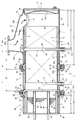
도 1은 DPF의 단면 설명도이다.
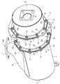
도 2는 DPF의 외관 사시도이다.
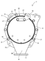
도 3은 DPF에 있어서의 배기 가스 상류측의 외관 측면도이다.
도 4는 DPF에 있어서의 배기 가스 하류측의 외관 측면도이다.
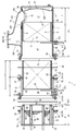
도 5는 DPF의 분리 단면 설명도이다.
도 6은 협지 플랜지의 분리 측면도이다.
도 7은 촉매측 접합 플랜지의 확대 측면 단면도이다.
도 8은 배기 가스 상류측에 있는 센서 보스체의 부착부를 나타내는 확대 단면도이다.
도 9는 DPF에 있어서의 배기 가스 상류측의 확대 측면 단면도이다.
도 10은 DPF 탑재의 디젤엔진을 냉각팬측으로부터 본 사시도이다.
도 11은 DPF 탑재의 디젤엔진을 배기 매니폴드측으로부터 본 측면도이다.
도 12는 DPF 탑재의 디젤엔진을 플라이 휠측으로부터 본 측면도이다.1 is an explanatory cross-sectional view of a DPF.
2 is an external perspective view of the DPF.
3 is an external side view of the exhaust gas upstream side in the DPF.
4 is an external side view of the exhaust gas downstream of the DPF.
5 is an exploded cross-sectional view of the DPF.
6 is an exploded side view of the pinching flange.
7 is an enlarged side sectional view of the catalyst-side bonding flange.
8 is an enlarged cross-sectional view showing an attachment portion of the sensor boss body on the upstream side of the exhaust gas.
9 is an enlarged side sectional view of the exhaust gas upstream side in the DPF.
10 is a perspective view of a DPF-equipped diesel engine seen from the cooling fan side.
11 is a side view of the DPF-equipped diesel engine seen from the exhaust manifold side.
12 is a side view of the DPF-equipped diesel engine viewed from the flywheel side.
이하, 본원 발명을 구체화한 배기 가스 정화 장치를 도면에 의거하여 설명한다. 또한, 이하의 설명에서는 디젤 파티큘레이트 필터(1)에 있어서의 배기 가스 유입구(12)측을 좌측이라고 하고, 마찬가지로 소음기(30)측을 우측이라고 하고 있다. 이러한 특정 방향이나 위치를 나타내는 용어는 설명의 편의를 위해서 사용한 것이며, 본원 발명의 기술적 범위를 한정하는 것은 아니다.Hereinafter, the exhaust gas purification device embodying the present invention will be described based on the drawings. In the following description, the exhaust gas inlet 12 side in the
(1) 배기 가스 정화 장치의 개략 구조(1) Outline structure of the exhaust gas purification device
우선, 도 1∼도 4를 참조하면서 배기 가스 정화 장치의 개략 구조에 대하여 설명한다. 도 1∼도 4에 나타내는 바와 같이, 배기 가스 정화 장치로서의 연속 재생식의 디젤 파티큘레이트 필터(1)[이하, DPF(1)라고 함]를 구비하고 있다. DPF(1)에 의해, 디젤엔진(70)의 배기 가스 중의 입자상 물질(PM)의 제거에 추가하여, 디젤엔진(70)의 배기 가스 중의 일산화탄소(CO)나 탄화수소(HC)를 저감시키도록 구성하고 있다.First, the schematic structure of the exhaust gas purification device will be described with reference to FIGS. 1 to 4. 1 to 4, a
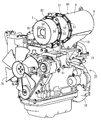
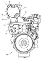
도 1 및 도 10∼도 13에 나타내는 바와 같이, 배기 가스 정화 장치로서의 DPF(1)는 배기 가스 중의 입자상 물질(PM) 등을 포집하기 위한 것이고, 디젤엔진(70)의 출력축(크랭크축)과 평행한 좌우 방향으로 길게 연장된 대략 원통 형상으로 구성되어 있다. 엔진(70)의 배기 매니폴드(71) 상에 DPF(1)를 배치한다. DPF(1)의 좌우 양측(배기 가스 이동 방향 상류측과 하류측)에는 배기 가스 입구관(16)과 배기 가스 출구관(34)이 디젤엔진(70)의 좌우로 갈라져서 설치되어 있다. DPF(1)의 배기 가스 도입측인 배기 가스 입구관(16)은 디젤엔진(70)의 배기 매니폴드(71)에 착탈 가능하게 볼트 체결되어 있다. DPF(1)의 배기 가스 배출측인 배기 가스 출구관(34)에는 테일 파이프(도시 생략)가 접속된다.1 and 10 to 13, the
도 1∼도 4에 나타내는 바와 같이, DPF(1)는 내열 금속 재료제인 정화 케이싱으로서의 DPF 케이싱(60)에 원통형의 내측 케이스(4, 20)를 통해서, 예를 들면 백금 등의 디젤 산화 촉매(2)와 허니콤 구조의 매연 필터(3)를 직렬로 배열하여 수용한 구조로 되어 있다. 도 14∼도 17에 나타내는 바와 같이, DPF(1)는 지지체로서의 플랜지측 브래킷 다리(61) 및 케이싱측 브래킷 다리(62)를 통해서 디젤엔진(70)의 실린더 헤드(72) 및 배기 매니폴드(71)에 부착되어 있다.As shown in Figs. 1 to 4, the
이 경우, 플랜지측 브래킷 다리(61)의 기단측은 DPF 케이싱(60)의 외주측에 있는 필터측 접합 플랜지(26)(상세는 후술함)에 착탈 가능하게 볼트 체결되어 있다. 또한, 케이싱측 브래킷 다리(62)의 기단측은 DPF 케이싱(60)의 촉매 외덮개체(9)(상세는 후술함)에 착탈 가능하게 볼트 체결되어 있다. 플랜지측 브래킷 다리(61)의 선단측은 실린더 헤드(72)에 있어서의 냉각팬(76)측의 측면에 착탈 가능하게 볼트 체결되어 있다. 케이싱측 브래킷 다리(62)의 선단측은 실린더 헤드(72)에 있어서의 플라이 휠 하우징(78)측의 측면에 착탈 가능하게 볼트 체결되어 있다.In this case, the proximal end side of the flange
배기 매니폴드(71)의 출구부에 배기 가스 입구관(16)의 입구 플랜지체(17)(상세는 후술함)를 체결시킴으로써, 배기 매니폴드(71)에 배기 가스 입구관(16)을 통해서 DPF(1)를 연통 접속하고 있다. 그 결과, DPF(1)는 각 브래킷 다리(61, 62)에 의해 디젤엔진(70)의 고강성 부품인 배기 매니폴드(71) 및 실린더 헤드(72)에 안정적으로 연결 지지되게 된다. 따라서, 진동 등에 의한 DPF(1)의 손상 억제를 도모할 수 있다.By fastening the
상기 구성에 있어서, 디젤엔진(70)의 배기 가스는 디젤엔진(70)의 배기 매니폴드(71)로부터 DPF 케이싱(60) 내의 디젤 산화 촉매(2)측으로 유입되고, 디젤 산화 촉매(2)로부터 매연 필터(3)측으로 이동해서 정화 처리된다. 배기 가스 중의 입자상 물질은 매연 필터(3)에 있어서의 각 셀간의 다공질 형상의 칸막이벽을 빠져 나갈 수 없다. 즉, 배기 가스 중의 입자상 물질은 매연 필터(3)에 포집된다. 그 후에, 디젤 산화 촉매(2) 및 매연 필터(3)를 통과한 배기 가스가 테일 파이프로부터 방출된다.In the above configuration, the exhaust gas of the
배기 가스가 디젤 산화 촉매(2) 및 매연 필터(3)를 통과할 때에 배기 가스의 온도가 재생 가능 온도(예를 들면, 약 300℃ 정도)를 초과하고 있으면, 디젤 산화 촉매(2)의 작용에 의해 배기 가스 중의 NO(일산화질소)가 불안정한 NO2(이산화질소)로 산화된다. 그리고, NO2가 NO로 되돌아올 때에 방출하는 O(산소)에 의해, 매연 필터(3)에 포집된 입자상 물질이 산화 제거된다. 또한, 매연 필터(3)에 입자상 물질이 퇴적된 경우에는 재생 가능 온도 이상으로 배기 가스 온도를 유지하면 입자상 물질이 산화 제거되기 때문에, 매연 필터(3)의 입자상 물질의 포집 능력이 회복되게[매연 필터(3)가 재생되게] 된다.When the exhaust gas passes through the
(2) 디젤 산화 촉매의 구조(2) Structure of diesel oxidation catalyst
이어서, 도 1, 도 5 및 도 9 등을 참조하면서 디젤엔진(70)이 배출한 배기 가스를 정화하는 가스 정화체(필터)의 일례인 디젤 산화 촉매(2)의 구조를 설명한다. 디젤 산화 촉매(2)는 내열 금속 재료제이며 대략 원통형의 촉매 내측 케이스(4) 내에 설치되어 있다. 촉매 내측 케이스(4)는 내열 금속 재료제이며 대략 원통형의 촉매 외측 케이스(5) 내에 설치되어 있다. 즉, 디젤 산화 촉매(2)의 외측에 세라믹 파이버제이며 매트 형상의 촉매 단열재(6)를 통해서 촉매 내측 케이스(4)를 피감(被嵌)시키고 있다. 디젤 산화 촉매(2)와 촉매 내측 케이스(4) 사이에 촉매 단열재(6)를 압입해서 디젤 산화 촉매(2)를 보호하고 있다. 또한, 촉매 내측 케이스(4)의 외측에 단면 대략 S자 형상의 박판제 지지체(7)를 통해서 촉매 외측 케이스(5)를 피감시키고 있다. 촉매 외측 케이스(5)는 상술의 DPF 케이싱(60)을 구성하는 요소 중 하나이다. 촉매 내측 케이스(4)에 전달되는 촉매 외측 케이스(5)의 응력(기계 진동이나 변형력)은 박판제 지지체(7)에 의해 저감되게 된다.Next, the structure of the
도 1, 도 5 및 도 9에 나타내는 바와 같이, 촉매 내측 케이스(4) 및 촉매 외측 케이스(5)의 일측 단부에 원판 형상의 촉매 내덮개체(8)를 용접에 의해 고착하고 있다. 촉매 내덮개체(8)의 외면측에는 촉매 외덮개체(9)가 볼트 및 너트에 의해 체결되어 있다. 디젤 산화 촉매(2)의 가스 유입측 끝면(2a)과 촉매 내덮개체(8)는 일정 거리(L1)[가스 유입 공간(11)]만큼 이간시키고 있다. 디젤 산화 촉매(2)의 가스 유입측 끝면(2a)과 촉매 내덮개체(8) 사이에 배기 가스 유입 공간(11)을 형성한다. 촉매 내측 케이스(4) 및 촉매 외측 케이스(5)에는 배기 가스 유입 공간(11)에 임하는 배기 가스 유입구(12)를 개구시키고 있다. 촉매 외측 케이스(5)에 있어서의 배기 가스 유입구(12)의 개구 가장자리는 촉매 내측 케이스(4)를 향해서 절곡 형성되어 있다. 상기 절곡 가장자리에 의해, 촉매 내측 케이스(4)의 개구 가장자리와 촉매 외측 케이스(5)의 개구 가장자리 사이의 간극을 폐쇄하고 있기 때문에, 촉매 내측 케이스(4)와 촉매 외측 케이스(5) 사이에 배기 가스가 유입되는 것을 방지할 수 있다.As shown in Figs. 1, 5, and 9, a catalyst
도 1, 도 5 및 도 9에 나타내는 바와 같이, 배기 가스 유입구(12)가 형성된 촉매 외측 케이스(5)의 외측면에 배기 가스 입구관(16)을 배치하고 있다. 배기 가스 입구관(16)은 상향 개구된 반할 통형으로 형성되어 있고, 대경측인 직사각형상의 상향 개구 단부(16b)가 배기 가스 유입구(12)를 덮고 또한 촉매 외측 케이스(5)의 길이(좌우) 방향으로 연장되도록 해서 촉매 외측 케이스(5)의 외측면에 용접 고정되어 있다. 따라서, 배기 가스 입구관(16)의 배기 가스 출구측인 상향 개구 단부(16b)는 촉매 외측 케이스(5)의 배기 가스 유입구(12)에 연통 접속되어 있다. 배기 가스 입구관(16) 중 촉매 외측 케이스(5)의 길이 중도부 부근에 있는 우단부에는 배기 가스 입구측으로서 소경 진원 형상의 하향 개구 단부(16a)를 개구시키고 있다. 하향 개구 단부(16a)의 외주부에 입구 플랜지체(17)가 용접 고정되어 있다. 입구 플랜지체(17)는 배기 매니폴드(71)의 배기 가스 배출측에 착탈 가능하게 볼트 체결되어 있다.1, 5 and 9, the exhaust
도 1, 도 5 및 도 9에 나타내는 바와 같이, 배기 가스 입구관(16)의 좌단부측이 촉매 외측 케이스(5)의 배기 가스 유입구(12)를 외측으로부터 덮고 있다. 배기 가스 입구관(16)의 우단부에 배기 가스 입구측으로서의 하향 개구 단부(16a)가 형성되어 있다. 즉, 배기 가스 유입구(12)에 대하여 배기 가스 입구관(16)의 하향 개구 단부(16a)는 DPF 케이싱(60)에 있어서의 배기 가스 하류측으로 오프셋해서 형성되어 있다[촉매 외측 케이스(5)의 우측에 위치를 어긋나게 해서 형성되어 있다]. 또한, 배기 가스 입구관(16)의 상향 개구 단부(16b)는 배기 가스 유입구(12)를 덮고 또한 촉매 외측 케이스(5)의 길이(좌우) 방향으로 연장되도록 해서 촉매 외측 케이스(5)의 외측면에 용접 고정되어 있다. 이 때문에, 촉매 외측 케이스(5)의 외측면과 배기 가스 입구관(16)의 관벽(201) 내측면에 의하여 배기 가스의 도입 통로(200)를 형성하고 있다. 그 결과, 배기 가스 입구관(16) 내[도입 통로(200) 내]의 배기 가스에 의해 DPF 케이싱(60)[촉매 외측 케이스(5)]을 가온할 수 있어, DPF 케이싱(60)[촉매 외측 케이스(5)] 내를 통과하는 배기 가스 온도의 저하를 억제하는 것이 가능해진다. 따라서, DPF(1)의 배기 가스 정화 성능을 향상시킬 수 있다. 또한, 배기 가스 입구관(16)을 DPF 케이싱(60)[촉매 외측 케이스(5)]의 강도 멤버로서 이용할 수 있어, DPF 케이싱(60)[촉매 외측 케이스(5)]을 후육화하거나 부품수를 극단적으로 늘리거나 하지 않고 간단한 구성으로 DPF 케이싱(60)[촉매 외측 케이스(5)]의 강성 향상을 도모할 수 있다.1, 5 and 9, the left end side of the exhaust
상기 구성에 있어서, 디젤엔진(70)의 배기 가스가 배기 매니폴드(71)로부터 배기 가스 입구관(16)으로 들어가고, 배기 가스 입구관(16)으로부터 배기 가스 유입구(12)를 통해서 배기 가스 유입 공간(11)으로 들어가고, 디젤 산화 촉매(2)에 이 좌측의 가스 유입측 끝면(2a)으로부터 공급된다. 디젤 산화 촉매(2)의 산화 작용에 의해 이산화질소(NO2)가 생성된다.In the above configuration, the exhaust gas of the
도 1, 도 5 및 도 9에 나타내는 바와 같이, 배기 가스 입구관(16)의 관벽(201) 중 DPF 케이싱(60)[촉매 외측 케이스(5)]을 따라 연장되는 부분을, 배기 가스 입구관(16)의 배기 가스 입구측[하향 개구 단부(16a)]부터 배기 가스 출구측[상향 개구 단부(16b)]을 향함에 따라서 DPF 케이싱(60)[촉매 외측 케이스(5)]의 외측면에 접근하도록 경사시킨 길이 경사부(202)에 형성하고 있다. 환언하면, 관벽(201) 중 DPF 케이싱(60)[촉매 외측 케이스(5)]을 따라 연장되는 부분은 측면에서 보았을 때 모서리를 비스듬히 잘라낸 듯한 형상의 길이 경사부(202)로 되어 있다. 배기 가스 입구관(16)의 길이 경사부(202)의 내측면은 DPF 케이싱(60)[촉매 외측 케이스(5)]의 배기 가스 유입구(12)로 덮여 있고, 배기 매니폴드(71)로부터 유입되는 배기 가스를 배기 가스 유입구(12)의 방향으로 편류시키도록 구성하고 있다.As shown in FIGS. 1, 5, and 9, a portion of the
상기 구성에 있어서, 배기 매니폴드(71)로부터 배기 가스 입구관(16)에 유입되는 배기 가스는 배기 가스 입구관(16)의 길이 경사부(202)의 내측면에 충돌해서 배기 가스 유입구(12)를 향해서 편류되고, 배기 가스 유입구(12) 경유로 배기 가스 유입 공간(11) 내로 스무스하게 안내된다. 즉, 배기 가스 입구관(16)의 길이 경사부(202)의 내측면을 배기 가스를 배기 가스 유입구(12)로 이송하는 안내면으로서 사용하고, 배기 가스 입구관(16)을 DPF 케이싱(60)[촉매 외측 케이스(5)]의 강도 멤버로서 이용할 수 있어, DPF 케이싱(60)[촉매 외측 케이스(5)]을 후육화하거나 부품수를 극단적으로 늘리거나 하지 않고 간단한 구성으로 DPF 케이싱(60)[촉매 외측 케이스(5)]의 강성 향상을 도모할 수 있는 것이면서, 배기 가스 입구관(16)의 길이 경사부(202)의 내측면에 의해 배기 매니폴드(71)로부터의 배기 가스를 DPF 케이싱(60)[촉매 외측 케이스(5)] 내로 스무스하게 안내할 수 있다. 따라서, DPF 케이싱(60)[촉매 외측 케이스(5)] 내의 가스 정화체인 디젤 산화 촉매(2)의 광역에 배기 가스를 공급할 수 있어, 디젤 산화 촉매(2)를 효율적으로 활용하는 것에 기여한다.In the above configuration, the exhaust gas flowing into the exhaust
도 1, 도 5 및 도 9에 나타내는 바와 같이, 배기 가스 입구관(16)의 관벽(201) 중 배기 가스 유출구이기도 한 배기 가스 출구관(34) 부근의 부분은, 배기 가스 입구관(16)의 배기 가스 입구측[하향 개구 단부(16a)]으로부터 배기 가스 출구측[상향 개구 단부(16b)]을 향함에 따라서 배기 가스 입구측[하향 개구 단부(16a)]의 중심선(C)(도 1 및 도 9 참조)으로부터 떨어지도록 경사진 폭 경사부(203)에 형성하고 있다. 환언하면, 관벽(201) 중 배기 가스 출구관(34) 부근의 대략 절반부는 하향 개구 단부(16a)로부터 상향 개구 단부(16b)를 향해서 반경이 넓어지는 나팔 형상의 폭 경사부(203)로 되어 있다. 이 경우, 배기 가스 입구관(16)의 관벽(201) 내측면 중 배기 가스 출구관(34) 부근의 부분에서는 배기 가스가 DPF 케이싱(60)[촉매 외측 케이스(5)]의 외측면에 충돌하지만, 상기 부분의 용적이 확보되기 때문에 선회류나 난류의 형성이 배기 가스 유입구(12)보다 배기 가스 상류측에서도 행해지게 된다. 따라서, 디젤 산화 촉매(2)의 배기 가스 상류측의 끝면(2a)[가스 유입측 끝면(2a)]에 한층 더 확실하게 배기 가스를 균등 공급할 수 있다.1, 5, and 9, a portion of the
도 1, 도 5 및 도 9에 나타내는 바와 같이, DPF 케이싱(60)[촉매 외측 케이스(5)]에 있어서의 배기 가스 유입구(12) 부근의 측단부 중 촉매 내덮개체(8)의 내면측에 밖을 향해서 오목해지는 오목면부(204)를 형성하고 있다. 따라서, 촉매 내덮개체(8)는 오목면부(204)의 존재에 의해 내면측의 대략 중앙부를 가장 오목하게 한 밥공기 형상으로 되어 있다. 이 때문에, DPF 케이싱(60)[촉매 외측 케이스(5)]의 배기 가스 유입구(12)로부터 촉매 내덮개체(8)의 오목면부(204)를 향해서 배기 가스를 공급할 수 있고, 오목면부(204)에 의한 배기 가스 확산 작용에 의해 디젤 산화 촉매(2)의 배기 가스 상류측[배기 가스 유입 공간(11)]에 있어서 선회류나 난류를 간단하게 형성할 수 있다. 이 때문에, 디젤 산화 촉매(2)의 배기 가스 상류측의 끝면[가스 유입측 끝면(2a)]에 배기 가스를 가능한 한 균등하게 공급할 수 있다.1, 5 and 9, the inner surface side of the catalyst
(3) 매연 필터의 구조(3) Structure of soot filter
이어서, 도 1, 도 5 및 도 9를 참조하여 디젤엔진(70)이 배출한 배기 가스를 정화하는 가스 정화체(필터)의 일례인 매연 필터(3)의 구조를 설명한다. 매연 필터(3)는 내열 금속 재료제이며 대략 원통형의 필터 내측 케이스(20) 내에 설치된다. 필터 내측 케이스(20)는 내열 금속 재료제이며 대략 원통형의 필터 외측 케이스(21) 내에 설치된다. 즉, 매연 필터(3)의 외측에 세라믹 파이버제이며 매트 형상의 필터 단열재(22)를 통해서 필터 내측 케이스(20)를 피감시키고 있다. 필터 외측 케이스(21)는 촉매 외측 케이스(5)와 함께 상술한 DPF 케이싱(60)을 구성하는 요소 중 하나이다. 또한, 매연 필터(3)와 필터 내측 케이스(20) 사이에 필터 단열재(22)를 압입해서 매연 필터(3)를 보호하고 있다.Next, with reference to FIGS. 1, 5 and 9, the structure of the
도 1, 도 5 및 도 9에 나타내는 바와 같이, 능선이 직선의 원통 형상으로 형성된 촉매 내측 케이스(4)는 디젤 산화 촉매(2)를 수용하는 상류측 통부(4a)와, 후술하는 필터 내측 케이스(20)가 삽입되는 하류측 통부(4b)에 의해 구성되어 있다. 또한, 상류측 통부(4a)와 하류측 통부(4b)는 대략 동일 지름의 원통이며, 일체 형상으로 되어 있다. 또한, 촉매 내측 케이스(4)의 외주에 용접 고정하는 박판 형상 링형의 촉매측 접합 플랜지(25)와, 필터 내측 케이스(20)의 외주에 용접 고정하는 박판 형상 링형의 필터측 접합 플랜지(26)를 구비한다. 촉매측 접합 플랜지(25)와 필터측 접합 플랜지(26)는 단면이 대략 L자의 도넛 형상으로 형성되어 있다.As shown in Figs. 1, 5, and 9, the catalyst
촉매 내측 케이스(4)에 있어서의 하류측 통부(4b)의 단부에는 촉매측 접합 플랜지(25)의 내주측을 용접 고정하고 있다. 촉매 외측 케이스(5)의 외주측(방사 방향)을 향해서 촉매측 접합 플랜지(25)의 외주측을 돌출시키고 있다. 촉매측 접합 플랜지(25)의 절곡 모서리부는 계단 형상의 단차부(25a)로 되어 있다. 촉매 외측 케이스(5)에 있어서의 배기 가스 하류측의 단부가 촉매측 접합 플랜지(25)의 단차부(25a)에 용접 고정되어 있다. 한편, 필터 내측 케이스(20)의 외주 중 길이 중도부(배기 가스 이동 방향의 중도부)에 필터측 접합 플랜지(26)의 내주측을 용접 고정하고 있다. 필터 외측 케이스(21)의 외주측(방사 방향)을 향해서 필터측 접합 플랜지(26)의 외주측을 돌출시키고 있다. 필터측 접합 플랜지(26)의 절곡 모서리부도 계단 형상의 단차부(26a)로 되어 있다. 필터 외측 케이스(21)에 있어서의 배기 가스 상류측의 단부가 필터측 접합 플랜지(26)의 단차부(26a)에 용접 고정되어 있다. 또한, 필터 내측 케이스(20)는 능선이 직선의 원통 형상으로 형성되어 있다. 필터 내측 케이스(20)의 배기 가스 상류측의 단부와 배기 가스 하류측의 단부는 대략 동일 지름의 원통이며, 일체 형상으로 되어 있다.The inner circumferential side of the catalyst
디젤 산화 촉매(2)의 외경과 매연 필터(3)의 외경은 동일하게 형성된다. 필터 단열재(22)의 두께에 비해서 촉매 단열재(6)의 두께를 크게 형성한다. 한편, 촉매 내측 케이스(4)와 필터 내측 케이스(20)는 동일 판 두께의 재료에 의해 형성된다. 촉매 내측 케이스(4)의 하류측 통부(4b)의 내경에 비해서 필터 내측 케이스(20)의 외경은 작게 형성된다. 촉매 내측 케이스(4)의 내주면과 필터 내측 케이스(20)의 외주면 사이에는 하류측 간극(23)이 형성된다. 하류측 간극(23)은 상기 각 케이스(4, 20)의 판 두께(예를 들면, 1.5밀리미터)보다 큰 치수(예를 들면, 2밀리미터)로 형성한다. 이와 같이 구성하면, 예를 들면 상기 각 케이스(4, 20)가 녹슬거나 열변형되거나 해도 촉매 내측 케이스(4)의 하류측 통부(4b)에 필터 내측 케이스(20)의 배기 가스 상류측의 단부를 간단하게 출납 가능하게 된다.The outer diameter of the
도 1∼도 5 및 도 8에 나타내는 바와 같이, 개스킷(24)을 통해서 촉매측 접합 플랜지(25)와 필터측 접합 플랜지(26)를 맞댄다. 각 외측 케이스(5, 21)의 외주측을 둘러싸는 한 쌍의 후판 형상의 중앙 협지 플랜지(51, 52)에 의해 각 접합 플랜지(25, 26)를 배기 가스 이동 방향의 양측으로부터 끼운다. 볼트(27) 및 너트(28)에 의해 각 중앙 협지 플랜지(51, 52)를 체결하고, 각 중앙 협지 플랜지(51, 52)에 의해 각 접합 플랜지(25, 26)를 협지함으로써 촉매 외측 케이스(5)와 필터 외측 케이스(21)가 착탈 가능하게 연결된다.1 to 5 and 8, the catalyst-
도 1 및 도 8에 나타내는 바와 같이, 각 중앙 협지 플랜지(51, 52) 및 각 접합 플랜지(25, 26)를 통해서 촉매 외측 케이스(5)의 배기 가스 하류측의 단부에 필터 외측 케이스(21)의 배기 가스 상류측의 단부를 연결한 상태에서는 디젤 산화 촉매(2)와 매연 필터(3) 사이에 촉매 하류측 공간(29)이 형성된다. 즉, 디젤 산화 촉매(2)의 가스 유출측 끝면(2b)과, 매연 필터(3)[필터 내측 케이스(20)]의 도입측 끝면(3a)이 센서 부착용 간격(L2)만큼 떨어져서 대치하게 된다.1 and 8, the filter
도 1 및 도 5에 나타내는 바와 같이, 촉매 내측 케이스(4)에 있어서의 상류측 통부(4a)의 배기 가스 이동 방향의 원통 길이(L3)보다 촉매 외측 케이스(5)의 배기 가스 이동 방향의 원통 길이(L4)를 길게 형성한다. 필터 내측 케이스(20)의 배기 가스 이동 방향의 원통 길이(L5)보다 필터 외측 케이스(21)의 배기 가스 이동 방향의 원통 길이(L6)를 짧게 형성한다. 촉매 하류측 공간(29)의 센서 부착용 간격(L2)과, 촉매 내측 케이스(4)의 상류측 통부(4a)의 원통 길이(L3)와, 필터 내측 케이스(20)의 원통 길이(L5)를 가산한 길이(L2+L3+L5)는 촉매 외측 케이스(5)의 원통 길이(L4)와 필터 외측 케이스(21)의 원통 길이(L6)를 가산한 길이(L4+L6)에 거의 동일해지도록 구성되어 있다.1 and 5, the cylinder in the exhaust gas movement direction of the catalyst
또한, 필터 내측 케이스(20)의 배기 가스 상류측의 단부는 필터 외측 케이스(21)의 배기 가스 상류측의 단부로부터 각 케이스(20, 21)의 길이의 차(L7≒L5-L6)만큼 돌출되어 있다. 이 때문에, 촉매 외측 케이스(5)에 필터 외측 케이스(21)를 연결한 상태에서는 필터 외측 케이스(21)로부터 돌출된 필터 내측 케이스(20)의 배기 가스 상류측 치수(L7)만큼 촉매 외측 케이스(5)의 배기 가스 하류측[촉매 내측 케이스(4)의 하류측 통부(4b)]에 필터 내측 케이스(20)의 배기 가스 상류측의 단부가 삽입된다. 즉, 하류측 통부(4b)[촉매 하류측 공간(29)] 내에 필터 내측 케이스(20)의 배기 가스 상류측이 장착/분리 가능하게 삽입된다. 상기 설명 및 도 1로부터 알 수 있는 바와 같이, 디젤 산화 촉매(2)와 매연 필터(3)의 접속 경계 위치[촉매 하류측 공간(29)]에 대하여, 촉매 외측 케이스(5)와 필터 외측 케이스(21)를 연결하는 플랜지체[촉매측 접합 플랜지(25) 및 필터측 접합 플랜지(26)]를 오프셋시키고 있다. 환언하면, 촉매 하류측 공간(29)에 대하여 촉매측 접합 플랜지(25) 및 필터측 접합 플랜지(26)의 부착 위치를 어긋나게 하고 있다.In addition, the end of the filter
상기 구성에 있어서, 디젤 산화 촉매(2)의 산화 작용에 의해 생성된 이산화질소(NO2)가 매연 필터(3) 내에 일측 끝면[도입측 끝면(3a)]으로부터 공급된다. 디젤엔진(70)의 배기 가스 중에 포함된 입자상 물질(PM)은 매연 필터(3)에 포집되어서 이산화질소(NO2)에 의해 연속적으로 산화 제거된다. 디젤엔진(70)의 배기 가스 중의 입상 물질(PM)의 제거에 추가하여, 디젤엔진(70)의 배기 가스 중의 일산화탄소(CO)나 탄화수소(HC)의 함유량이 저감된다.In the above configuration, nitrogen dioxide (NO 2 ) produced by the oxidation action of the
(4) 소음기의 구조(4) Structure of the silencer
이어서, 도 1 및 도 5를 참조하면서 디젤엔진(70)이 배출한 배기 가스음을 감쇠시키는 소음기(30)의 구조에 대하여 설명한다. 도 1 및 도 5에 나타내는 바와 같이, 디젤엔진(70)이 배출한 배기 가스음을 감쇠시키는 소음기(30)는 내열 금속 재료제이며 대략 원통형의 소음 내측 케이스(31)와, 내열 금속 재료제이며 대략 원통형의 소음 외측 케이스(32)와, 소음 외측 케이스(32)의 배기 가스 하류측의 측단부에 용접에 의해 고착한 원판 형상의 소음 외덮개체(33)를 갖는다. 소음 외측 케이스(32) 내에 소음 내측 케이스(31)를 설치한다. 소음 외측 케이스(32)는 촉매 외측 케이스(5) 및 필터 외측 케이스(21)와 함께 상술한 DPF 케이싱(60)을 구성한다. 또한, 원통형의 소음 외측 케이스(32)의 직경은 원통형의 촉매 외측 케이스(5)의 직경이나 원통형의 필터 외측 케이스(21)의 직경과 대략 동일 치수이다.Next, with reference to FIGS. 1 and 5, the structure of the
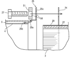
소음 내측 케이스(31)에 있어서의 배기 가스 상류측의 단부에 원판 형상의 소음 내덮개체(36)가 용접에 의해 고착되어 있다. 소음 내측 케이스(31) 내에는 배기 가스 이동 방향과 평행 형상으로 연장되는 한 쌍의 배기 가스 도입관(38)이 설치되어 있다. 각 배기 가스 도입관(38)의 배기 가스 상류측은 소음 내덮개체(36)를 관통하고 있지만, 각 배기 가스 도입관(38)의 배기 가스 상류측의 단부와 소음 내측 케이스(31)의 배기 가스 상류측의 단부의 위치는 측면 단면으로 보았을 때 거의 일치하고 있다. 각 배기 가스 도입관(38)에 있어서의 배기 가스 상류측의 단부는 그대로 개구시키고 있다. 각 배기 가스 도입관(38)에는 다수의 연통 구멍(39)이 형성되어 있다. 각 배기 가스 도입관(38)은 연통 구멍(39)을 통해서 팽창실(45)에 연통되어 있다. 팽창실(45)은 소음 내측 케이스(31)의 내부[소음 내덮개체(36)와 소음 외덮개체(33) 사이]에 형성되어 있다.In the noise
소음 외측 케이스(32)의 소음 외덮개체(33)에는 각 배기 가스 도입관(38)의 사이에 배치한 배기 가스 출구관(34)을 관통시키고 있다. 배기 가스 출구관(34)의 배기 가스 상류측은 소음 내덮개체(36)에 의해 폐쇄되어 있다. 배기 가스 출구관(34) 중 소음 내측 케이스(31) 내의 개소에는 다수의 배기 구멍(46)이 형성되어 있다. 각 배기 가스 도입관(38)은 다수의 연통 구멍(39), 팽창실(45) 및 다수의 배기 구멍(46)을 통해서 배기 가스 출구관(34)에 연통되어 있다. 배기 가스 출구관(34)의 타단측에 테일 파이프(도시 생략)가 접속된다. 상기 구성에 있어서, 소음 내측 케이스(31)의 양쪽 배기 가스 도입관(38) 내로 들어간 배기 가스는 복수의 연통 구멍(39), 팽창실(45) 및 다수의 배기 구멍(46)을 통해서 배기 가스 출구관(34)을 통과하고, 테일 파이프를 통해서 소음기(30) 밖으로 배출되게 된다.The noise
도 1 및 도 5에 나타내는 바와 같이, 필터 내측 케이스(20)의 배기 가스 하류측의 단부에 박판 형상 링형의 필터 출구측 접합 플랜지(40)의 내경측이 용접 고정되어 있다. 필터 외측 케이스(21)의 외주측(반경 외측, 방사 방향)을 향해서 필터 출구측 접합 플랜지(40)의 외경측을 돌출시키고 있다. 필터 출구측 접합 플랜지(40)의 외주측에 필터 외측 케이스(21)의 배기 가스 하류측의 단부가 용접 고정되어 있다. 소음 내측 케이스(31)의 배기 가스 상류측의 단부에 소음 외측 케이스(32)의 외주측(반경 외측)으로 돌출되는 박판 형상의 소음측 접합 플랜지(41)가 용접 고정되어 있다. 소음측 접합 플랜지(41)의 외주측에 소음 외측 케이스(32)의 배기 가스 상류측의 단부가 용접 고정되어 있다. 또한, 소음측 접합 플랜지(41)의 배기 가스 상류측에 소음 내측 케이스(31)의 배기 가스 상류측의 단부를 소정 원통 치수(L10)만큼 돌출시키고 있다. 또한, 필터 내측 케이스(20)와 소음 내측 케이스(31)는 대략 동일 지름의 원통이며, 필터 외측 케이스(21)와 소음 외측 케이스(32)는 대략 동일 지름의 원통이다.1 and 5, the inner diameter side of the thin ring-shaped filter outlet
도 1∼도 4 및 도 6에 나타내는 바와 같이, 개스킷(24)을 통해서 필터 출구측 접합 플랜지(40)와 소음측 접합 플랜지(41)를 맞대고, 각 외측 케이스(21, 32)의 외주측을 둘러싸는 한 쌍의 후판 형상의 출구 협지 플랜지(53, 54)에 의해 각 접합 플랜지(40, 41)를 배기 가스 이동 방향의 양측으로부터 협지시킨다. 그리고, 볼트(42) 및 너트(43)에 의해 각 접합 플랜지(40, 41)에 각 출구 협지 플랜지(53, 54)를 체결함으로써 필터 외측 케이스(21)와 소음 외측 케이스(32)가 착탈 가능하게 연결된다.1 to 4 and 6, the filter outlet
도 1 및 도 5에 나타내는 바와 같이, 소음 내측 케이스(31)의 배기 가스 이동 방향의 원통 길이(L8)보다 소음 외측 케이스(32)의 배기 가스 이동 방향의 원통 길이(L9)를 짧게 형성하고 있다. 소음 내측 케이스(31)의 배기 가스 상류측의 단부는 소음 외측 케이스(32)의 배기 가스 상류측의 단부[접합 플랜지(41)]로부터 각 케이스(31, 32)의 길이의 차(L10≒L8-L9)만큼 돌출되어 있다. 즉, 필터 외측 케이스(21)에 소음 외측 케이스(32)를 연결한 상태에서는 소음 내측 케이스(31)의 배기 가스 상류측의 단부가 돌출된 치수(L10)만큼 필터 외측 케이스(21)의 배기 가스 하류측의 단부[필터 출구측 접합 플랜지(40)] 내에 형성된 필터 하류측 공간(49)에 소음 내측 케이스(31)의 배기 가스 상류측의 단부가 삽입된다. 상기 설명 및 도 1로부터 알 수 있는 바와 같이, 매연 필터(3)의 접속 경계 위치[필터 하류측 공간(49)]에 대하여 필터 외측 케이스(21)와 소음 외측 케이스(32)를 연결하는 플랜지체[필터 출구측 접합 플랜지(40) 및 소음측 접합 플랜지(41)]를 오프셋시키고 있다. 환언하면, 필터 하류측 공간(49)에 대하여 필터 출구측 접합 플랜지(40) 및 소음측 접합 플랜지(41)의 부착 위치를 어긋나게 하고 있다.1 and 5, the cylinder length L9 in the exhaust gas movement direction of the noise
상기한 바와 같이 구성하면, 각 배기 가스 도입관(38)의 배기 가스 이동 방향의 길이를 확보하면서 소음기(30)[소음 외측 케이스(32)]의 배기 가스 이동 방향의 길이를 단축할 수 있게 된다. 따라서, 소음기(30)가 부착된 DPF(1)에 있어서 DPF(1) 전체로서의 콤팩트화와, 소음기(30)에 있어서의 소음 기능의 유지 향상을 양립할 수 있다.When configured as described above, it is possible to shorten the length of the exhaust gas movement direction of the silencer 30 (noise outer case 32) while securing the length of the exhaust
(5) 이웃하는 외측 케이스끼리의 연결 구조(5) Connection structure between neighboring outer cases
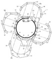
이어서, 도 1∼도 4 및 도 6을 참조하면서 이웃하는 외측 케이스(5, 21, 32)끼리의 연결 구조를 설명한다. 도 1∼도 4 및 도 6에 나타내는 바와 같이, 후판 형상의 중앙 협지 플랜지[51(52)]는 촉매 외측 케이스(5)[필터 외측 케이스(21)]의 둘레 방향으로 복수(실시형태에서는 2개)로 분할된 반원호체[51a, 51b(52a, 52b)]에 의해 구성되어 있다. 실시형태의 각 반원호체[51a, 51b(52a, 52b)]는 원호 형상(거의 반원 형상의 말굽형)으로 형성되어 있다. 촉매 외측 케이스(5)에 필터 외측 케이스(21)를 연결한 상태에서는 각 반원호체[51a, 51b(52a, 52b)]의 단부끼리가 원주 방향을 따라 맞대진다(접촉한다). 즉, 각 반원호체[51a, 51b(52a, 52b)]에 의해 촉매 외측 케이스(5)[필터 외측 케이스(21)]의 외주측이 환상으로 둘러싸이게 된다.Next, a connection structure between neighboring
중앙 협지 플랜지[51(52)]에는 둘레 방향을 따른 등간격으로 관통 구멍이 부착된 볼트 체결부(55)가 복수 설치되어 있다. 실시형태에서는 1세트의 중앙 협지 플랜지(51)에 대하여 10개소의 볼트 체결부(55)를 구비하고 있다. 각 반원호체[51a, 51b(52a, 52b)] 단위에서 보면, 원주 방향을 따른 등간격으로 5개소씩 볼트 체결부(55)가 설치되어 있다. 한편, 촉매측 접합 플랜지(25) 및 필터측 접합 플랜지(26)에는 중앙 협지 플랜지[51(52)]의 각 볼트 체결부(55)에 대응하는 볼트 구멍(56)이 관통 형성되어 있다.A plurality of
촉매 외측 케이스(5)와 필터 외측 케이스(21)를 연결할 때에 있어서는 촉매 외측 케이스(5)의 외주측을 촉매측의 양쪽 반원호체(51a, 51b)로 둘러쌈과 아울러 필터 외측 케이스(21)의 외주측을 필터측의 양쪽 반원호체(52a, 52b)로 둘러싸고, 개스킷(24)을 협지한 촉매측 접합 플랜지(25)와 필터측 접합 플랜지(26)를 이들 반원호체군[중앙 협지 플랜지(51, 52)]에 의해 배기 가스 이동 방향의 양측으로부터 협지한다. 이어서, 양측의 중앙 협지 플랜지(51, 52)의 볼트 체결부(55)와, 양쪽 접합 플랜지(25, 26)의 볼트 구멍(56)에 볼트(27)를 삽입해서 너트(28)로 체결한다. 그 결과, 양쪽 접합 플랜지(25, 26)가 양쪽 중앙 협지 플랜지(51, 52)로 끼워서 고정되고, 촉매 외측 케이스(5)와 필터 외측 케이스(21)의 연결이 완료된다. 여기에서, 촉매측의 반원호체(51a, 51b)와 필터측의 반원호체(52a, 52b)의 단부끼리의 맞댄 부분은 서로 72° 위상을 어긋나게 해서 위치시키도록 구성되어 있다.When the catalyst
도 1∼도 4에 나타내는 바와 같이, 후판 형상의 출구 협지 플랜지[53(54)]는 필터 외측 케이스(21)[소음 외측 케이스(32)]의 둘레 방향으로 복수(실시형태에서는 2개)로 분할된 반원호체[53a, 53b(54a, 54b)]에 의해 구성되어 있다. 실시형태의 각 반원호체[53a, 53b(54a, 54b)]는 중앙 협지 플랜지[51(52)]의 반원호체[51a, 51b(52a, 52b)]와 기본적으로 같은 형태인 것이다. 출구 협지 플랜지[53(54)]에도 둘레 방향을 따른 등간격으로 관통 구멍이 부착된 볼트 체결부(57)가 복수 설치되어 있다. 한편, 필터 출구측 접합 플랜지(40) 및 소음측 접합 플랜지(41)에는 출구 협지 플랜지[53(54)]의 각 볼트 체결부(57)에 대응하는 볼트 구멍(58)이 관통 형성되어 있다.As shown in Figs. 1 to 4, a plurality of (two in the embodiment) circumferential directions of the filter outer case 21 (noise outer case 32) of the plate-shaped outlet pinching flanges 53 (54) are provided. It is composed of divided semicircular arc bodies (53a, 53b (54a, 54b)). Each semicircular body [53a, 53b (54a, 54b)] of the embodiment is basically the same shape as the semicircular body [51a, 51b (52a, 52b)] of the central pinching flange [51 (52)]. The outlet clamping flange 53 (54) is also provided with a plurality of
필터 외측 케이스(21)와 소음 외측 케이스(32)를 연결할 때에 있어서는 필터 외측 케이스(21)의 외주측을 필터 출구측의 양쪽 반원호체(53a, 53b)로 둘러쌈과 아울러 소음 외측 케이스(32)의 외주측을 소음측의 양쪽 반원호체(54a, 54b)로 둘러싸고, 개스킷(24)을 협지한 필터 출구측 접합 플랜지(40)와 소음측 접합 플랜지(41)를 이들 반원호체군[출구 협지 플랜지(53, 54)]에 의해 배기 가스 이동 방향의 양측으로부터 협지한다. 이어서, 양측의 출구 협지 플랜지(53, 54)의 볼트 체결부(57)와, 양쪽 접합 플랜지(40, 41)의 볼트 구멍(58)에 볼트(42)를 삽입해서 너트(43)로 체결한다. 그 결과, 양쪽 접합 플랜지(40, 41)가 양쪽 출구 협지 플랜지(53, 54)로 끼워서 고정되고, 필터 외측 케이스(21)와 소음 외측 케이스(32)의 연결이 완료된다. 여기에서, 필터 출구측의 반원호체(53a, 53b)와 소음측의 반원호체(54a, 54b)의 단부끼리의 맞댄 부분은 서로 72° 위상을 어긋나게 해서 위치시키도록 구성되어 있다.When connecting the filter
도 1∼도 4 및 도 6에 나타내는 바와 같이, 엔진(70)이 배출한 배기 가스를 정화하는 가스 정화체(2, 3)와, 각 가스 정화체(2, 3)를 내장하는 각 내측 케이스(4, 20, 31)와, 각 내측 케이스(4, 20, 31)를 내장하는 각 외측 케이스(5, 21, 32)를 구비한다. 각 내측 케이스(4, 20, 31)는 각 외측 케이스(5, 21, 32)의 외주측으로 돌출되는 접합 플랜지(25, 26, 40, 41)를 통해서 각 외측 케이스(5, 21, 32)에 연결시킨다. 가스 정화체(2, 3), 각 내측 케이스(4, 20, 31) 및 각 외측 케이스(5, 21, 32)의 조합을 복수 구비하고, 각 접합 플랜지[25, 26(40, 41)]를 한 쌍의 협지 플랜지[51, 52(53, 54)]에 의해 협지 고정함으로써 복수의 외측 케이스(5, 21, 32)를 연결한다.1 to 4 and 6, the
이와 같이 구성하면, 이웃하는 접합 플랜지[25, 26(40, 41)]를 각 협지 플랜지[51, 52(53, 54)]에 의해 양측으로부터 끼워 부착해서 압접(밀착)할 수 있다. 또한, 협지 플랜지(51∼54)를 외측 케이스(5, 21, 32)에 용접하지 않고 별체로 구성하므로, 협지 플랜지(51∼54)와 외측 케이스(5, 21, 32)의 관계에 있어서 용접에 기인하는 응력 집중이나 변형 문제가 발생할 우려는 없다. 이 때문에, 각 접합 플랜지[25, 26(40, 41)]의 전체에 대략 균일한 압접력을 부여할 수 있음과 아울러, 협지 플랜지(51∼54)의 밀봉면(협지면)의 면압을 높은 상태로 유지할 수 있다. 그 결과, 각 접합 플랜지[25, 26(40, 41)]의 사이로부터의 배기 가스 누설을 확실하게 방지할 수 있다.With this configuration, the adjacent joining
도 1∼도 4 및 도 6에 나타내는 바와 같이, 각 협지 플랜지(51∼54)는 외측 케이스(5, 21, 32)의 둘레 방향으로 복수로 분할된 말굽형의 반원호체[51a, 51b(52a, 52b, 53a, 53b, 54a, 54b)]로 이루어지고, 복수의 반원호체[51a, 51b(52a, 52b, 53a, 53b, 54a, 54b)]에 의해 외측 케이스(5, 21, 32)의 외주측을 둘러싸도록 구성하고 있다. 따라서, 복수의 반원호체[51a, 51b(52a, 52b, 53a, 53b, 54a, 54b)]로 구성된 협지 플랜지(51∼54)이면서, 일체물과 마찬가지의 장착 상태로 할 수 있다. 이 때문에, 링 형상의 플랜지에 비해서 협지 플랜지(51∼54)의 장착이 용이하여, 장착 작업성을 향상시킬 수 있다. 또한, 가공 비용이나 장착 비용을 억제하면서, 밀봉성이 높은 DPF(1)를 구성할 수 있다.1 to 4 and 6, each of the pinching
(6) 접합 플랜지의 상세 구조(6) Detailed structure of joint flange
이어서, 각 접합 플랜지(25, 26, 40)의 상세 구조를 설명한다. 각 접합 플랜지(25, 26, 40)는 모두 기본적으로 같은 구조이기 때문에, 촉매 내측 케이스(4)와 촉매 외측 케이스(5)에 용접 고정되는 촉매측 접합 플랜지(25)를 대표예로 해서 도 7을 참조하면서 설명한다. 도 7에 나타내는 바와 같이, 촉매측 접합 플랜지(25)의 절곡 모서리부에 계단상의 단차부(25a)가 형성되어 있다. 상기 단차부(25a)에 촉매 외측 케이스(5)의 배기 가스 하류측의 단부를 피감시키고, 촉매 외측 케이스(5)의 배기 가스 하류측의 단부에 단차부(25a)를 용접 고정시키고 있다.Next, the detailed structure of each joining
한편, 촉매 내측 케이스(4)[촉매 외측 케이스(5)]의 배기 가스 이동 방향으로 촉매측 접합 플랜지(25)에 있어서의 L형의 내경측 단부(25b)가 연설되어 있다. 촉매 내측 케이스(4)의 배기 가스 하류측의 단부에 내경측 단부(25b)를 피감시키고, 촉매 내측 케이스(4)에 내경측 단부(25b)를 용접 고정시키고 있다. 한편, 촉매 외측 케이스(5)의 외주로부터 방사 방향(연직 방향)을 향해서 촉매측 접합 플랜지(25)의 L형의 외경측 단부(25c)를 연설시키고 있다. 촉매측 접합 플랜지(25)의 단면 L자 형상과 단차부(25a)의 존재에 의하여, 촉매측 접합 플랜지(25)의 높은 강성이 확보되어 있다.On the other hand, the L-shaped inner diameter
또한, 협지 플랜지(51, 52) 및 접합 플랜지(25, 26)의 각 볼트 구멍(56)을 관통한 볼트(27)에 너트(28)를 나사 고정시킴으로써 협지 플랜지(51, 52)와 접합 플랜지(25, 26)를 체결시키고, 촉매측 접합 플랜지(25)의 외경측 단부(25c)를 협지 플랜지(51, 52)에 의해 협지하는 구조는 상술한 바와 같다.In addition, the
(6) 가스 온도 센서의 부착 구조(6) Gas temperature sensor attachment structure
이어서, 도 1, 도 8 및 도 9를 참조하면서 DPF(1)에 부설하는 가스 온도 센서(109, 112)에 대하여 설명한다. 도 1, 도 8 및 도 9에 나타내는 바와 같이, 촉매 내측 케이스(4)의 외주면 중 상류측 통부(4a)와 하류측 통부(4b) 사이에 원통 형상의 센서 보스체(110)의 일단이 용접 고정되어 있다. 촉매 외측 케이스(5)의 센서 부착 개구(5a)로부터 상기 촉매 외측 케이스(5)의 외측을 향해서 방사 방향으로 센서 보스체(110)의 타단을 연장시키고 있다. 즉, 촉매 내측 케이스(4)의 외주면 중 디젤 산화 촉매(2)와 매연 필터(3)의 접속 경계 위치[촉매 하류측 공간(29)]의 근방에 배기 가스 센서 지지용의 센서 보스체(110)가 촉매 외측 케이스(5)를 관통하도록 설치되어 있다. 센서 보스체(110)의 타단에 센서 부착 볼트(111)를 나사 고정한다. 센서 부착 볼트(111)에, 예를 들면 서미스터형의 상류측 가스 온도 센서(109)를 관통시키고, 센서 보스체(110)에 센서 부착 볼트(111)를 통해서 상류측 가스 온도 센서(109)를 지지시킨다. 촉매 하류측 공간(29) 내에 상류측 가스 온도 센서(109)의 검출 부분을 돌입시키고 있다. 상기 구성에 있어서 디젤 산화 촉매(2)의 가스 유출측 끝면(2b)으로부터 배기 가스가 배출된 경우에는, 그 배기 가스 온도가 상류측 가스 온도 센서(109)에 의해 검출된다.Next,
도 8 및 도 9에 나타내는 바와 같이, 배기 가스 상류측의 센서 보스체(110)는 디젤 산화 촉매(2)에 있어서 배기 가스 이동 방향과 직교하는 가스 유출측 끝면(2b)의 연장 상이며, 또한 매연 필터(3)에 있어서 배기 가스 이동 방향과 직교하는 도입측 끝면(3a)의 연장 상에 위치하고 있다. 이 경우, 디젤 산화 촉매(2)의 가스 유출측 끝면(2b) 및 매연 필터(3)의 도입측 끝면(3a)과, 상류측 가스 온도 센서(109)의 배치 간격을 매우 짧게 설정하는(근접시키는) 것이 가능해지기 때문에, DPF(1) 전체의 콤팩트화를 도모할 수 있음과 아울러 상류측 가스 온도 센서(109)의 검출 정밀도를 향상시킬 수 있어, DPF(1)에 대한 재생 제어 등의 성능 향상에 기여한다.8 and 9, the
도 1 및 도 5에 나타내는 바와 같이, 필터 내측 케이스(20)의 외주면 중 필터 하류측 공간(49)의 근방에도 원통 형상의 센서 보스체(110)의 일단이 용접 고정되어 있다. 필터 외측 케이스(21)의 센서 부착 개구(21a)로부터 상기 필터 외측 케이스(21)의 외측을 향해서 방사 방향으로 센서 보스체(110)의 타단을 연장시키고 있다. 즉, 필터 내측 케이스(20)의 외주면 중 매연 필터(3)의 접속 경계 위치의 근방에 배기 가스 센서 지지용의 센서 보스체(110)가 필터 외측 케이스(21)를 관통하도록 설치되어 있다. 센서 보스체(110)의 타단에 센서 부착 볼트(111)를 나사 고정한다. 센서 부착 볼트(111)에, 예를 들면 서미스터형의 하류측 가스 온도 센서(112)를 관통시키고, 센서 보스체(110)에 센서 부착 볼트(111)를 통해서 하류측 가스 온도 센서(112)를 지지시킨다. 필터 하류측 공간(49) 내에 하류측 가스 온도 센서(112)의 검출 부분을 돌입시키고 있다. 상기 구성에 있어서 매연 필터(3)의 배출측 끝면(3b)으로부터 배기 가스가 배출된 경우에는, 그 배기 가스 온도가 하류측 가스 온도 센서(112)에 의해 검출된다. 또한, 상세한 것은 도시하지 않지만 양쪽 가스 온도 센서(109, 112)에 대한 센서 보스체(110)와 마찬가지로 차압 센서의 센서 보스체를 구성할 수 있는 것은 말할 필요도 없다.1 and 5, one end of the cylindrical
(7) 정리(7) Theorem
상기 기재 및 도 1, 도 5 및 도 9로부터 분명하게 나타내는 바와 같이, 엔진(70)이 배출한 배기 가스를 정화하는 가스 정화체(2)와, 상기 가스 정화체(2)를 수용하는 정화 케이싱(60)과, 상기 정화 케이싱(60)의 배기 가스 유입구(12)에 연통되는 배기 가스 입구관(16)과, 상기 정화 케이싱(60)의 배기 가스 유출구에 연통되는 배기 가스 출구관(34)을 구비하고, 상기 배기 가스 유입구(12)를 덮고 또한 상기 정화 케이싱(60)의 길이 방향으로 연장되도록 상기 배기 가스 입구관(16)을 상기 정화 케이싱(60)에 부착하고, 상기 정화 케이싱(60)의 외측면과 상기 배기 가스 입구관(16)의 관벽(201) 내측면에 의하여 배기 가스의 도입 통로(200)를 형성하고 있는 배기 가스 정화 장치(1)에 있어서, 상기 배기 가스 입구관(16)의 관벽(201) 중 상기 정화 케이싱(60)을 따라 연장되는 부분(202)을 상기 배기 가스 입구관(16)의 배기 가스 입구측(16a)으로부터 배기 가스 출구측(16b)을 향함에 따라서 상기 정화 케이싱(60)의 외측면에 접근하도록 경사시키고 있기 때문에, 상기 배기 가스 입구관(16) 내[상기 도입 통로(200) 내]의 배기 가스에 의해 상기 정화 케이싱(60)을 가온할 수 있어, 상기 정화 케이싱(60) 내를 통과하는 배기 가스 온도의 저하를 억제하는 것이 가능해진다. 따라서, 배기 가스 정화 장치(1)의 배기 가스 정화 성능을 향상시킬 수 있다. 상기 관벽(201) 중 상기 정화 케이싱(60)을 따라 연장되는 부분(202)의 경사 형상이 배기 가스를 배기 가스 유입구(12)로 이송하는 안내면이 된다. 상기 배기 가스 입구관(16)을 상기 정화 케이싱(60)의 강도 멤버로서 이용할 수 있어, 상기 정화 케이싱(60)을 후육화하거나 부품수를 극단적으로 늘리거나 하지 않고 간단한 구성으로 상기 정화 케이싱(60)의 강성 향상을 도모할 수 있는 것이면서, 상기 관벽(201) 중 상기 정화 케이싱(60)을 따라 연장되는 부분(202)의 경사 형상에 의해 상기 엔진(70)으로부터의 배기 가스를 상기 정화 케이싱(60) 내로 스무스하게 안내할 수 있다. 상기 정화 케이싱(60) 내의 상기 가스 정화체(2)의 광역에 배기 가스를 공급할 수 있어, 상기 가스 정화체(2)를 효율적으로 활용하는 것에 기여한다.As clearly indicated from the above description and FIGS. 1, 5 and 9, a gas purifying body 2 for purifying the exhaust gas emitted by the engine 70 and a purifying casing accommodating the gas purifying body 2 60, an exhaust gas inlet pipe 16 communicating with the exhaust gas inlet 12 of the purification casing 60, and an exhaust gas outlet pipe 34 communicating with the exhaust gas outlet of the purification casing 60 It is provided, and the exhaust gas inlet tube 12 is also attached to the exhaust gas inlet pipe 16 to the purification casing 60 so as to extend in the longitudinal direction of the purification casing 60, and the purification casing 60 ) In the exhaust gas purifying device (1) forming an inlet passage 200 for exhaust gas by an outer surface of the exhaust gas inlet pipe (16) and an inner surface of the pipe wall (201) of the exhaust gas inlet pipe (16), The portion 202 of the tube wall 201 of 16) extending along the purification casing 60 Since the exhaust gas inlet pipe 16 is inclined to approach the outer surface of the purification casing 60 from the exhaust gas inlet side 16a toward the exhaust gas outlet side 16b, the exhaust gas inlet pipe (16) The purification casing 60 can be heated by the exhaust gas in the inside (in the introduction passage 200), and it is possible to suppress a decrease in the temperature of the exhaust gas passing through the purification casing 60. Becomes Therefore, the exhaust gas purification performance of the exhaust
상기 기재 및 도 1, 도 5 및 도 9로부터 분명하게 나타내는 바와 같이, 상기 정화 케이싱(60)에 있어서의 상기 배기 가스 유입구(12) 부근의 측단부(8)의 내면측에 밖을 향해서 오목해지는 오목면부(204)를 형성하고 있기 때문에, 상기 정화 케이싱(60)의 상기 배기 가스 유입구(12)로부터 상기 오목면부(204)를 향해서 배기 가스를 공급할 수 있고, 상기 오목면부(204)에 의한 배기 가스 확산 작용에 의해 상기 가스 정화체(2)의 배기 가스 상류측에 있어서 선회류나 난류를 간단하게 형성할 수 있다. 이 때문에, 상기 가스 정화체(2)의 배기 가스 상류측의 끝면(2a)에 배기 가스를 가능한 한 균등하게 공급할 수 있다.As clearly indicated from the above description and FIGS. 1, 5, and 9, the inner side of the
상기 기재 및 도 1, 도 5 및 도 9로부터 분명하게 나타내는 바와 같이, 상기 배기 가스 입구관(16)의 관벽(201) 중 상기 배기 가스 유출구(34) 부근의 부분(203)은 상기 배기 가스 입구관(16)의 상기 배기 가스 입구측(16a)으로부터 상기 배기 가스 출구측(16b)을 향함에 따라서 상기 배기 가스 입구측(16a)의 중심선(C)으로부터 떨어지도록 경사져 있다. 상기 배기 가스 입구관(16)의 관벽(201) 내측면 중 상기 배기 가스 유출구(34) 부근의 부분(203)에서는 배기 가스가 상기 정화 케이싱(60)의 외측면에 충돌하지만, 상기 부분(203)의 용적이 확보되기 때문에 선회류나 난류의 형성이 상기 배기 가스 유입구(12)보다 배기 가스 상류측에서도 행해지게 된다. 상기 가스 정화체(2)의 배기 가스 상류측의 끝면(2a)에 한층 더 확실하게 배기 가스를 균등 공급할 수 있다.As clearly indicated from the above description and FIGS. 1, 5 and 9, a
또한, 본원 발명에 있어서의 각 부의 구성은 도시의 실시형태에 한정되는 것은 아니고, 본원 발명의 취지를 일탈하지 않는 범위에서 여러 가지로 변경이 가능하다.In addition, the structure of each part in the present invention is not limited to the illustrated embodiment, and various modifications can be made without departing from the spirit of the present invention.
1 : DPF(디젤 파티큘레이트 필터)
2 : 디젤 산화 촉매(가스 정화체)
3 : 매연 필터(가스 정화체)
4 : 촉매 내측 케이스
5 : 촉매 외측 케이스
20 : 필터 내측 케이스
21 : 필터 외측 케이스
25, 26, 40, 41 : 접합 플랜지(플랜지체)
30 : 소음기
31 : 소음 내측 케이스
32 : 소음 외측 케이스
38 : 배기 가스 도입관
60 : DPF 케이싱
70 : 디젤엔진
200 : 도입 통로
201 : 관벽
202 : 길이 경사부
203 : 폭 경사부
204 : 오목면부1: DPF (Diesel Particulate Filter) 2: Diesel oxidation catalyst (gas purifier)
3: Soot filter (gas purification body) 4: Catalyst inner case
5: catalyst outer case 20: filter inner case
21: filter outer case
25, 26, 40, 41: joint flange (flange body)
30: silencer 31: noise inner case
32: noise outer case 38: exhaust gas introduction pipe
60: DPF casing 70: diesel engine
200: introduction passage 201: pipe wall
202: length slope 203: width slope
204: concave surface portion
Claims (5)
상기 배기 가스 입구관의 관벽을 상기 배기 가스 입구관의 배기 가스 입구측으로부터 배기 가스 출구측을 향함에 따라서 상기 케이싱의 외측면에 접근하도록 경사시키고 있는 것을 특징으로 하는 배기 가스 정화 장치.In the exhaust gas purification apparatus having a casing and an exhaust gas inlet pipe communicating with the exhaust gas inlet of the casing,
The exhaust gas purifying apparatus characterized in that the pipe wall of the exhaust gas inlet pipe is inclined to approach the outer surface of the casing as it goes from the exhaust gas inlet side of the exhaust gas inlet pipe toward the exhaust gas outlet side.
상기 배기 가스 입구관이, 상기 배기 가스 유입구를 덮도록 상기 케이싱에 부착되는 것을 특징으로 하는 배기 가스 정화 장치.According to claim 1,
Exhaust gas purification apparatus, characterized in that the exhaust gas inlet pipe is attached to the casing to cover the exhaust gas inlet.
상기 배기 가스 입구관이, 상기 케이싱의 길이 방향을 따라 연설되는 것을 특징으로 하는 배기 가스 정화 장치.According to claim 1,
The exhaust gas inlet pipe, the exhaust gas purification apparatus, characterized in that the speech along the longitudinal direction of the casing.
상기 케이싱에 있어서의 상기 배기 가스 유입구 부근의 측단부의 내면측에 밖을 향해서 오목해지는 오목면부를 형성하고 있는 것을 특징으로 하는 배기 가스 정화 장치.According to claim 1,
An exhaust gas purifying device, characterized in that a concave surface portion concave outward is formed on an inner surface side of the side end portion near the exhaust gas inlet in the casing.
상기 배기 가스 입구관의 관벽 중 배기 가스 유출구 부근의 부분은 상기 배기 가스 입구관의 상기 배기 가스 입구측으로부터 상기 배기 가스 출구측을 향함에 따라서 상기 배기 가스 입구측의 중심선으로부터 떨어지도록 경사져 있는 것을 특징으로 하는 배기 가스 정화 장치.
The method according to any one of claims 1 to 4,
A portion of the pipe wall of the exhaust gas inlet pipe near the exhaust gas outlet port is inclined to be separated from the center line of the exhaust gas inlet side toward the exhaust gas outlet side from the exhaust gas inlet side of the exhaust gas inlet pipe. Exhaust gas purification device.
Applications Claiming Priority (3)
| Application Number | Priority Date | Filing Date | Title |
|---|---|---|---|
| JPJP-P-2012-283485 | 2012-12-26 | ||
| JP2012283485A JP6055305B2 (en) | 2012-12-26 | 2012-12-26 | Exhaust gas purification device |
| PCT/JP2013/084140 WO2014103890A1 (en) | 2012-12-26 | 2013-12-19 | Exhaust gas purification device |
Related Parent Applications (1)
| Application Number | Title | Priority Date | Filing Date |
|---|---|---|---|
| KR1020157012653A Division KR102104693B1 (en) | 2012-12-26 | 2013-12-19 | Exhaust gas purification device |
Publications (1)
| Publication Number | Publication Date |
|---|---|
| KR20200043507A true KR20200043507A (en) | 2020-04-27 |
Family
ID=51020977
Family Applications (2)
| Application Number | Title | Priority Date | Filing Date |
|---|---|---|---|
| KR1020157012653A KR102104693B1 (en) | 2012-12-26 | 2013-12-19 | Exhaust gas purification device |
| KR1020207010930A KR20200043507A (en) | 2012-12-26 | 2013-12-19 | Exhaust gas purification device |
Family Applications Before (1)
| Application Number | Title | Priority Date | Filing Date |
|---|---|---|---|
| KR1020157012653A KR102104693B1 (en) | 2012-12-26 | 2013-12-19 | Exhaust gas purification device |
Country Status (6)
| Country | Link |
|---|---|
| US (1) | US9790832B2 (en) |
| EP (1) | EP2940266B1 (en) |
| JP (1) | JP6055305B2 (en) |
| KR (2) | KR102104693B1 (en) |
| CN (1) | CN104884755B (en) |
| WO (1) | WO2014103890A1 (en) |
Families Citing this family (3)
| Publication number | Priority date | Publication date | Assignee | Title |
|---|---|---|---|---|
| US10428718B2 (en) * | 2016-05-09 | 2019-10-01 | Tenneco Automotive Operating Company Inc. | Compact inline inlet with integrated cast ring |
| GB2603883B (en) * | 2018-04-02 | 2022-11-23 | Cummins Emission Solutions Inc | Aftertreatment system including noise reducing components |
| WO2020009694A1 (en) | 2018-07-03 | 2020-01-09 | Cummins Emission Solutions Inc. | Body mixing decomposition reactor |
Citations (2)
| Publication number | Priority date | Publication date | Assignee | Title |
|---|---|---|---|---|
| JP2004263593A (en) | 2003-02-28 | 2004-09-24 | Calsonic Kansei Corp | Diesel particulate filter device |
| JP2005194949A (en) | 2004-01-08 | 2005-07-21 | Hino Motors Ltd | Emission control device |
Family Cites Families (11)
| Publication number | Priority date | Publication date | Assignee | Title |
|---|---|---|---|---|
| JPS6131131Y2 (en) * | 1981-03-26 | 1986-09-10 | ||
| JP4920532B2 (en) | 2007-09-13 | 2012-04-18 | 日野自動車株式会社 | Exhaust purification device |
| DE102008022081A1 (en) * | 2008-05-05 | 2009-11-12 | J. Eberspächer GmbH & Co. KG | Exhaust gas treatment device |
| JP5215789B2 (en) | 2008-09-18 | 2013-06-19 | ヤンマー株式会社 | Exhaust gas purification device |
| EP2333263B1 (en) * | 2008-09-18 | 2017-05-10 | Yanmar Co., Ltd. | Engine device |
| EP2341227B1 (en) | 2008-10-28 | 2018-08-29 | Yanmar Co., Ltd. | Engine device for mounting on working vehicle |
| WO2010101018A1 (en) * | 2009-03-05 | 2010-09-10 | ヤンマー株式会社 | Engine device |
| DE102009024534A1 (en) | 2009-06-10 | 2010-12-16 | J. Eberspächer GmbH & Co. KG | exhaust gas cleaning device |
| JP5390281B2 (en) * | 2009-07-02 | 2014-01-15 | ヤンマー株式会社 | Exhaust gas purification device |
| JP5381661B2 (en) * | 2009-12-01 | 2014-01-08 | トヨタ自動車株式会社 | Exhaust purification device |
| WO2011118527A1 (en) * | 2010-03-23 | 2011-09-29 | ヤンマー株式会社 | Exhaust gas purification device |
-
2012
- 2012-12-26 JP JP2012283485A patent/JP6055305B2/en active Active
-
2013
- 2013-12-19 WO PCT/JP2013/084140 patent/WO2014103890A1/en active Application Filing
- 2013-12-19 CN CN201380066325.3A patent/CN104884755B/en active Active
- 2013-12-19 US US14/655,382 patent/US9790832B2/en active Active
- 2013-12-19 EP EP13867554.1A patent/EP2940266B1/en active Active
- 2013-12-19 KR KR1020157012653A patent/KR102104693B1/en active IP Right Grant
- 2013-12-19 KR KR1020207010930A patent/KR20200043507A/en not_active Application Discontinuation
Patent Citations (2)
| Publication number | Priority date | Publication date | Assignee | Title |
|---|---|---|---|---|
| JP2004263593A (en) | 2003-02-28 | 2004-09-24 | Calsonic Kansei Corp | Diesel particulate filter device |
| JP2005194949A (en) | 2004-01-08 | 2005-07-21 | Hino Motors Ltd | Emission control device |
Also Published As
| Publication number | Publication date |
|---|---|
| EP2940266A4 (en) | 2016-10-26 |
| US9790832B2 (en) | 2017-10-17 |
| EP2940266A1 (en) | 2015-11-04 |
| CN104884755B (en) | 2017-09-22 |
| WO2014103890A1 (en) | 2014-07-03 |
| KR20150099719A (en) | 2015-09-01 |
| JP2014125970A (en) | 2014-07-07 |
| CN104884755A (en) | 2015-09-02 |
| JP6055305B2 (en) | 2016-12-27 |
| EP2940266B1 (en) | 2017-11-01 |
| KR102104693B1 (en) | 2020-04-24 |
| US20160215671A1 (en) | 2016-07-28 |
Similar Documents
| Publication | Publication Date | Title |
|---|---|---|
| KR101756240B1 (en) | Exhaust gas purification device | |
| KR101736263B1 (en) | Exhaust gas purification device | |
| KR101783732B1 (en) | Exhaust gas purification device | |
| JP5543803B2 (en) | Exhaust gas purification device | |
| KR102104693B1 (en) | Exhaust gas purification device | |
| JP5767736B2 (en) | Exhaust gas purification device | |
| JP5814434B2 (en) | Exhaust gas purification device | |
| JP5550957B2 (en) | Exhaust gas purification device | |
| JP5340193B2 (en) | Exhaust gas purification device | |
| JP5550958B2 (en) | Exhaust gas purification device | |
| JP5467900B2 (en) | Exhaust gas purification device | |
| JP2014029157A (en) | Engine device | |
| JP5551497B2 (en) | Exhaust gas purification device | |
| JP5788564B2 (en) | Exhaust gas purification device | |
| JP5685294B2 (en) | Exhaust gas purification device | |
| JP5793208B2 (en) | Exhaust gas purification device | |
| JP2014025477A (en) | Engine device |
Legal Events
| Date | Code | Title | Description |
|---|---|---|---|
| A107 | Divisional application of patent | ||
| A201 | Request for examination | ||
| E902 | Notification of reason for refusal | ||
| E601 | Decision to refuse application |