KR20200042813A - Hollow Shaft Motor - Google Patents
Hollow Shaft Motor Download PDFInfo
- Publication number
- KR20200042813A KR20200042813A KR1020180123435A KR20180123435A KR20200042813A KR 20200042813 A KR20200042813 A KR 20200042813A KR 1020180123435 A KR1020180123435 A KR 1020180123435A KR 20180123435 A KR20180123435 A KR 20180123435A KR 20200042813 A KR20200042813 A KR 20200042813A
- Authority
- KR
- South Korea
- Prior art keywords
- hollow shaft
- shaft motor
- bearing
- housing
- coupled
- Prior art date
Links
Images


Classifications
-
- H—ELECTRICITY
- H02—GENERATION; CONVERSION OR DISTRIBUTION OF ELECTRIC POWER
- H02K—DYNAMO-ELECTRIC MACHINES
- H02K5/00—Casings; Enclosures; Supports
- H02K5/04—Casings or enclosures characterised by the shape, form or construction thereof
- H02K5/16—Means for supporting bearings, e.g. insulating supports or means for fitting bearings in the bearing-shields
- H02K5/173—Means for supporting bearings, e.g. insulating supports or means for fitting bearings in the bearing-shields using bearings with rolling contact, e.g. ball bearings
- H02K5/1737—Means for supporting bearings, e.g. insulating supports or means for fitting bearings in the bearing-shields using bearings with rolling contact, e.g. ball bearings radially supporting the rotor around a fixed spindle; radially supporting the rotor directly
-
- H—ELECTRICITY
- H02—GENERATION; CONVERSION OR DISTRIBUTION OF ELECTRIC POWER
- H02K—DYNAMO-ELECTRIC MACHINES
- H02K7/00—Arrangements for handling mechanical energy structurally associated with dynamo-electric machines, e.g. structural association with mechanical driving motors or auxiliary dynamo-electric machines
- H02K7/003—Couplings; Details of shafts
-
- H—ELECTRICITY
- H02—GENERATION; CONVERSION OR DISTRIBUTION OF ELECTRIC POWER
- H02K—DYNAMO-ELECTRIC MACHINES
- H02K1/00—Details of the magnetic circuit
- H02K1/06—Details of the magnetic circuit characterised by the shape, form or construction
- H02K1/22—Rotating parts of the magnetic circuit
- H02K1/27—Rotor cores with permanent magnets
- H02K1/2706—Inner rotors
- H02K1/272—Inner rotors the magnetisation axis of the magnets being perpendicular to the rotor axis
- H02K1/274—Inner rotors the magnetisation axis of the magnets being perpendicular to the rotor axis the rotor consisting of two or more circumferentially positioned magnets
- H02K1/2753—Inner rotors the magnetisation axis of the magnets being perpendicular to the rotor axis the rotor consisting of two or more circumferentially positioned magnets the rotor consisting of magnets or groups of magnets arranged with alternating polarity
- H02K1/278—Surface mounted magnets; Inset magnets
-
- H—ELECTRICITY
- H02—GENERATION; CONVERSION OR DISTRIBUTION OF ELECTRIC POWER
- H02K—DYNAMO-ELECTRIC MACHINES
- H02K21/00—Synchronous motors having permanent magnets; Synchronous generators having permanent magnets
- H02K21/12—Synchronous motors having permanent magnets; Synchronous generators having permanent magnets with stationary armatures and rotating magnets
- H02K21/14—Synchronous motors having permanent magnets; Synchronous generators having permanent magnets with stationary armatures and rotating magnets with magnets rotating within the armatures
- H02K21/16—Synchronous motors having permanent magnets; Synchronous generators having permanent magnets with stationary armatures and rotating magnets with magnets rotating within the armatures having annular armature cores with salient poles
-
- H—ELECTRICITY
- H02—GENERATION; CONVERSION OR DISTRIBUTION OF ELECTRIC POWER
- H02K—DYNAMO-ELECTRIC MACHINES
- H02K3/00—Details of windings
- H02K3/46—Fastening of windings on the stator or rotor structure
- H02K3/52—Fastening salient pole windings or connections thereto
- H02K3/521—Fastening salient pole windings or connections thereto applicable to stators only
- H02K3/522—Fastening salient pole windings or connections thereto applicable to stators only for generally annular cores with salient poles
-
- H—ELECTRICITY
- H02—GENERATION; CONVERSION OR DISTRIBUTION OF ELECTRIC POWER
- H02K—DYNAMO-ELECTRIC MACHINES
- H02K5/00—Casings; Enclosures; Supports
- H02K5/04—Casings or enclosures characterised by the shape, form or construction thereof
-
- H—ELECTRICITY
- H02—GENERATION; CONVERSION OR DISTRIBUTION OF ELECTRIC POWER
- H02K—DYNAMO-ELECTRIC MACHINES
- H02K5/00—Casings; Enclosures; Supports
- H02K5/04—Casings or enclosures characterised by the shape, form or construction thereof
- H02K5/16—Means for supporting bearings, e.g. insulating supports or means for fitting bearings in the bearing-shields
- H02K5/161—Means for supporting bearings, e.g. insulating supports or means for fitting bearings in the bearing-shields radially supporting the rotary shaft at both ends of the rotor
-
- H—ELECTRICITY
- H02—GENERATION; CONVERSION OR DISTRIBUTION OF ELECTRIC POWER
- H02K—DYNAMO-ELECTRIC MACHINES
- H02K5/00—Casings; Enclosures; Supports
- H02K5/04—Casings or enclosures characterised by the shape, form or construction thereof
- H02K5/16—Means for supporting bearings, e.g. insulating supports or means for fitting bearings in the bearing-shields
- H02K5/173—Means for supporting bearings, e.g. insulating supports or means for fitting bearings in the bearing-shields using bearings with rolling contact, e.g. ball bearings
- H02K5/1732—Means for supporting bearings, e.g. insulating supports or means for fitting bearings in the bearing-shields using bearings with rolling contact, e.g. ball bearings radially supporting the rotary shaft at both ends of the rotor
-
- H—ELECTRICITY
- H02—GENERATION; CONVERSION OR DISTRIBUTION OF ELECTRIC POWER
- H02K—DYNAMO-ELECTRIC MACHINES
- H02K5/00—Casings; Enclosures; Supports
- H02K5/04—Casings or enclosures characterised by the shape, form or construction thereof
- H02K5/22—Auxiliary parts of casings not covered by groups H02K5/06-H02K5/20, e.g. shaped to form connection boxes or terminal boxes
- H02K5/225—Terminal boxes or connection arrangements
-
- H—ELECTRICITY
- H02—GENERATION; CONVERSION OR DISTRIBUTION OF ELECTRIC POWER
- H02K—DYNAMO-ELECTRIC MACHINES
- H02K7/00—Arrangements for handling mechanical energy structurally associated with dynamo-electric machines, e.g. structural association with mechanical driving motors or auxiliary dynamo-electric machines
- H02K7/08—Structural association with bearings
- H02K7/083—Structural association with bearings radially supporting the rotary shaft at both ends of the rotor
-
- H—ELECTRICITY
- H02—GENERATION; CONVERSION OR DISTRIBUTION OF ELECTRIC POWER
- H02K—DYNAMO-ELECTRIC MACHINES
- H02K7/00—Arrangements for handling mechanical energy structurally associated with dynamo-electric machines, e.g. structural association with mechanical driving motors or auxiliary dynamo-electric machines
- H02K7/08—Structural association with bearings
- H02K7/086—Structural association with bearings radially supporting the rotor around a fixed spindle; radially supporting the rotor directly
- H02K7/088—Structural association with bearings radially supporting the rotor around a fixed spindle; radially supporting the rotor directly radially supporting the rotor directly
-
- H—ELECTRICITY
- H02—GENERATION; CONVERSION OR DISTRIBUTION OF ELECTRIC POWER
- H02K—DYNAMO-ELECTRIC MACHINES
- H02K2203/00—Specific aspects not provided for in the other groups of this subclass relating to the windings
- H02K2203/09—Machines characterised by wiring elements other than wires, e.g. bus rings, for connecting the winding terminations
Abstract
Description
본 발명은 모터에 관한 것이다. 보다 구체적으로 본 발명은 통합 브레이크 시스템에 사용되는 중공축 모터에 절곡된 형태의 중공축과 새로운 하우징 구조를 적용함으로써, 중공축과 하우징을 프레스 가공에 의하여 생산이 가능하도록 함으로써 제조 비용을 낮추고 조립성 및 생산성을 증대시킨 모터에 관한 것이다.The present invention relates to a motor. More specifically, the present invention lowers manufacturing cost and assembly by applying a hollow shaft and a new housing structure in a bent shape to a hollow shaft motor used in an integrated brake system, thereby allowing the hollow shaft and the housing to be produced by press working. And a motor that increases productivity.
일반적으로 브레이크 시스템은 브레이크에 작용하는 힘을 증폭시키기 위해 마스터 실린더에서 압력을 발생시켜 제동이 필요한 모듈에 압력을 제공한다. 이와 같이 마스터 실린더에 압력을 발생시키는 장치로 중공축 모터가 사용되고 있다. 이러한 중공축 모터는 속이 비어있는 샤프트, 즉 중공축을 모터의 원리에 의해 회전시키고, 중공축의 내부에 스크류를 적용하여 스크류의 회전 운동을 직선운동으로 변환하는 원리를 이용하고 있다. 스크류의 직선 운동은 피스톤을 작동시켜 마스터 실린더 내에 필요한 압력을 생성하거나 제거하는 작용을 한다.In general, the brake system generates pressure in the master cylinder to amplify the force acting on the brake, providing pressure to the module requiring braking. As described above, a hollow shaft motor is used as a device for generating pressure in the master cylinder. The hollow shaft motor uses a principle of rotating a hollow shaft, that is, a hollow shaft according to the principle of the motor, and converting the rotational motion of the screw into a linear motion by applying a screw inside the hollow shaft. The linear motion of the screw acts to actuate the piston to create or remove the necessary pressure in the master cylinder.
최근 통합 전자 브레이크 시스템(IDB: Integrated Dynamic Brake)에는 이러한 중공축을 갖는 모터를 주로 사용하고 있다. 이와 같은 모터의 중공축은 중공축 내부에서 작동하는 스크류와 피스톤에 의해서 큰 압력을 발생시켜야 하기 때문에 중공축을 지지하는 베어링에는 상당한 축방향 하중이 작용한다. 따라서, 중공축의 회전을 지지하기 위하여 4점 접촉 볼베어링(four point contact ball bearing)을 적용하기도 한다.Recently, an integrated electronic brake system (IDB: Integrated Dynamic Brake) mainly uses a motor having such a hollow shaft. Since the hollow shaft of such a motor must generate a large pressure by a screw and a piston operating inside the hollow shaft, a significant axial load is applied to the bearing supporting the hollow shaft. Therefore, a four point contact ball bearing is also applied to support rotation of the hollow shaft.
대한민국 공개특허공보 제10-2016-0001681호에서는 중공축과 하우징을 프레스 가공에 의해 제조할 수 있는 구조의 모터에 대하여 개시하고 있다. 여기서, 하우징의 하부 쪽은 닫혀진 구조이기 때문에 조립이 어렵고, 4점 접촉 볼베어링을 설치하기 어려운 단점이 있다.Republic of Korea Patent Publication No. 10-2016-0001681 discloses a motor having a structure capable of manufacturing a hollow shaft and a housing by press working. Here, since the lower side of the housing is a closed structure, it is difficult to assemble, and there is a disadvantage that it is difficult to install a four-point contact ball bearing.
대한민국 공개특허공보 제10-2017-0006535호에서는 하우징의 하부 쪽을 개방시켜 별도의 커버를 조립하는 구조에 대하여 제시하고 있으며, 하우징은 딥 드로잉과 같은 프레스 가공에 의해 제조되는 기술에 대하여 제시하고 있다. 이러한 구조에 의하면, 중공축을 지지하는 베어링을 지지하기 위해 하우징의 하부 쪽에 별도의 커버를 조립하여 중공축에 걸리는 하중을 지지할 수 있도록 하고 있다. 따라서, 조립성과 생산성이 저하되는 문제점이 있다.Republic of Korea Patent Publication No. 10-2017-0006535 proposes a structure for assembling a separate cover by opening the lower side of the housing, and the housing is presented for a technique manufactured by press processing such as deep drawing. . According to this structure, in order to support the bearing supporting the hollow shaft, a separate cover is assembled to the lower side of the housing to support the load applied to the hollow shaft. Therefore, there is a problem that the assembly performance and productivity are lowered.
이에 본 발명자들은 상술한 문제점을 해결하기 위하여 새로운 구조의 중공축 모터를 제안하고자 한다.Accordingly, the present inventors intend to propose a hollow shaft motor having a new structure in order to solve the above-described problems.
본 발명의 목적은 중공축과 하우징을 프레스 가공에 의하여 생산이 가능하도록 함으로써 제조 비용을 낮추고 조립성 및 생산성을 증대시킬 수 있는 새로운 구조의 중공축 모터를 제공하는 것이다.An object of the present invention is to provide a hollow shaft motor having a new structure that can reduce the manufacturing cost and increase the assembly and productivity by enabling the hollow shaft and the housing to be produced by press working.
본 발명의 상기 목적 및 기타 목적은 아래 설명하는 본 발명에 의하여 모두 용이하게 달성될 수 있다.The above and other objects of the present invention can be easily achieved by the present invention described below.
본 발명에 따른 중공축 모터는Hollow shaft motor according to the present invention
원통 형상의 하우징(11);A
상기 하우징(11)의 상부에 결합되는 상부 커버(12);An
상기 하우징(11)의 하부에 결합되는 하부 커버(15);A
상기 하우징(11)의 내부에 위치하는 스테이터 어셈블리(20); 및A
상기 스테이터 어셈블리(20)의 내부에 위치하여 회전하는 로터 어셈블리(30);A
를 포함하여 이루어지고, 상기 로터 어셈블리(30)는 중공축(31), 상기 중공축(31)의 외주에 결합된 로터 코어(32), 및 상기 로터 코어(32)의 외주에 부착된 복수 개의 마그넷(33)을 포함하는 것을 특징으로 한다.The
본 발명에서, 상기 중공축(31)은 In the present invention, the
원통형의 요크 결합부(311)와, 요크 결합부(311)의 지름보다 더 큰 지름을 갖는 상부 베어링 지지부(312)와, 상부 베어링 지지부(312)의 하부에 내측으로 절곡된 형상의 상부 베어링 안착부(313)와, 상기 요크 결합부(311)의 하부로 돌출된 하부 베어링 지지부(316)를 포함하여도 좋다.A cylindrical
본 발명에서, 상기 상부 커버(12)의 중앙 부분으로부터 하부로 연장된 하부 슬리브(12D)가 형성되며, 상기 하부 슬리브(12D)는 상기 요크 결합부(311)의 내부로 연장되는 것이 바람직하다.In the present invention, a
본 발명에서, 상기 하부 슬리브(12D)의 상부 쪽에는 상부 베어링(13)이 결합되며, 상기 상부 베어링(13)의 외륜은 상기 상부 베어링 지지부(312)의 회전을 지지하는 것이 바람직하다.In the present invention, the
본 발명에서, 상기 하우징의 하부 중심부에는 하부로 돌출된 하부 돌출부(115)가 형성되고, 상기 하부 돌출부(115)의 중앙의 공간은 하부 개방부(116)를 이루게 되며, 하부 돌출부(115)는 재료가 절곡되어 하부로부터 상부로 연장된 하부 베어링 안착부(117)를 형성하는 것이 바람직하다.In the present invention, the lower central portion of the
본 발명에서, 상기 하부 베어링 안착부(117)에는 하부 베어링(14)의 상부가 안착되고, 상기 하부 베어링(14)의 외주는 상기 하부 돌출부(115)의 내측에 압입되며, 상기 하부 베어링(14)은 상기 중공축(31)의 회전을 지지하는 것이 바람직하다.In the present invention, the upper portion of the
본 발명에서, 상기 하부 돌출부(115)의 외주면에 결합되는 하부 커버(15)를 더 포함하여도 좋다.In the present invention, the
본 발명에서, 상기 하부 베어링(14)과 상기 하부 커버(15) 사이의 공간에 삽입되어 상기 하부 베어링(14)의 축방향 하중을 지지하기 위한 스토퍼(16)를 더 포함하여도 좋다.In the present invention, it may be further inserted into a space between the
본 발명에서, 상기 스토퍼(16)는 상기 하부 커버(15)와 일체로 형성된 하나의 부재이어도 좋다.In the present invention, the
본 발명은 모터의 중공축과 하우징을 프레스 가공에 의하여 생산이 가능하도록 함으로써 제조 비용을 낮추고 조립성 및 생산성을 증대시킬 수 있는 효과를 갖는다.The present invention has the effect of lowering the manufacturing cost and increasing the assembly and productivity by enabling the hollow shaft and the housing of the motor to be produced by press working.
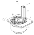
도 1은 본 발명에 따른 중공축 모터를 나타낸 사시도이다.
도 2는 본 발명에 따른 중공축 모터를 분해하여 나타낸 사시도이다.
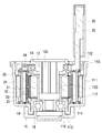
도 3은 도 1의 A-A' 방향으로 절단하여 바라본 단면도이다.
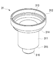
도 4는 본 발명에 따른 중공축 모터의 중공축을 나타낸 사시도이다.
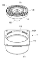
도 5는 본 발명에 따른 중공축 모터의 상부 커버와 하우징을 위로부터 바라본 사시도이다.
도 6은 본 발명에 따른 중공축 모터의 상부 커버와 하우징을 아래로부터 바라본 사시도이다.
이하에서 첨부된 도면을 참조로 하여 본 발명에 대해 상세히 설명하기로 한다.1 is a perspective view showing a hollow shaft motor according to the present invention.
2 is an exploded perspective view showing a hollow shaft motor according to the present invention.
FIG. 3 is a cross-sectional view of FIG. 1 cut along AA ′.
4 is a perspective view showing a hollow shaft of the hollow shaft motor according to the present invention.
5 is a perspective view of the hollow shaft motor according to the present invention as viewed from above.
6 is a perspective view of the hollow shaft motor according to the present invention, as viewed from below.
Hereinafter, the present invention will be described in detail with reference to the accompanying drawings.
도 1은 본 발명에 따른 중공축 모터(100)를 나타낸 사시도이고, 도 2는 본 발명에 따른 중공축 모터(100)를 분해하여 나타낸 사시도이며, 도 3은 도 1의 A-A' 방향으로 절단하여 바라본 단면도이다.1 is a perspective view showing a
도 1 내지 도 3을 함께 참조하면, 본 발명에 따른 중공축 모터(100)는 하우징(11)과, 하우징(11) 내측에 결합되는 스테이터 어셈블리(20)와, 스테이터 어셈블리(20)의 내측에 위치하는 로터 어셈블리(30)로 이루어진다.1 to 3 together, the
하우징(11)은 트랜스퍼 금형과 같은 프레스 가공 설비에 의해 연속적인 공정을 통해 제조가 가능하다. 하우징(11)은 원통 형상의 몸체부(111)를 가지며 상부 및 하부가 개방된 형상을 갖는다. 하우징(11)의 상부 쪽으로 개방된 부분은 상부 개방부(112)이며, 이 상부 개방부의 주위로 수평 방향으로 연장된 플랜지부(113)가 형성된다. 상부 개방부(112)에는 상부 커버(12)가 결합된다. 플랜지부(113)는 브레이크 시스템의 블럭(도시되지 않음)과 결합된다. 몸체부(111)의 하부에는 수평방향으로 중심쪽을 향해 연장되는 저면부(114)가 형성되며, 저면부(114)의 중심부에는 하부로 돌출된 하부 돌출부(115)가 형성된다. 하부 돌출부(115)의 중앙의 공간은 하부 개방부(116)를 이루게 되며, 하부 돌출부(115)는 프레스 가공에 의해 재료가 절곡되어 하부로부터 상부로 연장된 하부 베어링 안착부(117)를 형성한다. The
하부 돌출부(115)는 재료가 절곡되어 겹쳐진 구조를 가짐으로써 강도가 보강되기 때문에 하부 베어링(14)에 하중이 많이 걸리더라도 이를 지지하는데 도움이 된다. 하부 돌출부(115)의 내측면에는 하부 베어링(14)이 압입되어 결합되며, 하부 베어링(14)의 외륜의 상부는 하부 베어링 안착부(117)에 지지된다. 하부 베어링 안착부(117)의 중심 부분의 개방된 공간 및 하부 개방부(116)에는 에는 중공축(31)의 하부 말단 부분이 위치한다. 하부 베어링 안착부(117)는 바람직하게 저면부(114)보다 높은 위치에서 내부로 절곡되어 연장된다. 이를 통해, 하부 베어링(14)의 안정적인 지지가 가능한 구조를 갖는다.Since the
상부 커버(12)는 원판 형상을 가지며 그 외주 부분이 하부로 연장되어 있다. 이 연장된 부분의 외주면은 하우징(11)의 상부 개방부(112) 내측에 압입되어 결합된다. 상부 커버(12)의 중앙 부분에 형성된 중앙 공간(12A)에는 중공축(31)의 회전에 의해 상하로 이동하기 위한 피스톤(도시되지 않음)이 위치한다. 상부 커버(12)의 일측에는 터미널 공간(12B)이 형성되어 있어, 버스바 터미널(25)이 외부 전원과 연결될 수 있도록 한다. 상부 커버(12)의 상부에는 반경방향으로 돌출된 복수 개의 결합 돌기(12C)가 형성되어 있다. 이 결합 돌기(12C)와 대응하는 하우징(11)의 상부 개방부(112) 둘레에는 결합 홈(112A)이 형성되어 있어, 결합 돌기(12C)가 결합 홈(112A)에 끼워져 결합되도록 하고 있다. The
중앙 공간(12A)은 하부로 연장되어 있는데, 중앙 공간(12A)을 이루도록 상부 커버(12)의 중앙 부분으로부터 하부로 연장된 하부 슬리브(12D)가 형성된다. 하부 슬리브(12D)의 상부 쪽에는 상부 베어링(13)이 결합된다. 상부 베어링(13)의 외륜은 중공축(31)의 상부에 지지되어, 중공축(31)의 회전을 지지한다. 하부 슬리브(12D)는 중공축(31)의 중앙의 공간에서 하부로 연장되어 있는데, 이러한 구조를 통해 중공축(31)과 슬리브의 내측의 중앙 공간(12A)을 어느 정도 독립적으로 구분해주고 있다. 이를 통해, 상하 운동을 하는 피스톤(도시되지 않음)의 운동 공간을 독립적으로 확보할 수 있는 잇점이 있다.The
하부 커버(15)는 하우징(11)의 하부 돌출부(115)에 결합되어 하부 개방부(116)를 덮는다. 하부 커버(15)는 하부 돌출부(115)의 외측에 압입되거나, 탭 가공을 통해 나사 결합으로 결합하여도 좋다. 하부 돌출부(115)의 내주면의 공간에는 스토퍼(16)가 위치하는데, 스토퍼(16)는 하부 베어링(14)과 하부 커버(15) 사이에 개재되어 하부 베어링(14)에 걸리는 축방향 하중을 지지하는 구조를 가진다. 이러한 스토퍼(16)는 하부 커버(15)와 별개의 부재이어도 좋고, 별개의 부재가 아닌 하부 커버(15)와 일체로 형성되어 하나의 부재를 이루도록 하여도 좋다.The
스테이터 어셈블리(20)는 하우징(11)의 몸체부(111) 내측에 압입되어 고정되는 스테이터 코어(21)와, 스테이터 코어(21)의 상부에 결합되는 상부 인슐레이터(22) 및 하부에 결합되는 하부 인슐레이터(23)를 포함한다. 각 인슐레이터에는 코일(도시되지 않음)이 권선되고, 이 코일은 상부 인슐레이터(22)의 상부에 결합되어 있는 버스바 하우징(24)의 버스바(도시되지 않음)에 전기적으로 연결된다. 버스바는 버스바 터미널(25)에 전기적으로 연결되어 외부 전원이 인가될 수 있다. 버스바 터미널(25)는 터미널 커버(26)에 의해 둘러싸여 보호되고 있다.The
로터 어셈블리(30)는 스테이터 어셈블리(20)의 내측에 위치하여 회전한다. 이를 위해 중공축(31)과, 중공축(31)의 외주에 결합된 로터 코어(32)와, 로터 코어(32)의 외주에 부착된 복수 개의 마그넷(33)을 포함한다. 중공축(31)의 상세한 구조는 도 4를 함께 참조하여 설명하기로 한다.The
도 4는 본 발명에 따른 중공축 모터(100)의 중공축(31)을 나타낸 사시도이다. 도 3 및 도 4에 도시된 바와 같이, 본 발명의 중공축(31)은 원통형의 요크 결합부(311)를 갖는다. 요크 결합부(311)의 외주면에는 로터 코어(32)가 결합된다. 로터 코어(32)의 외주면에는 복수 개의 마그넷(33)이 부착된다. 필요에 따라, 로터 코어(32)가 생략되고, 복수 개의 마그넷(33)이 요크 결합부(311)의 외주면에 직접 부착될 수도 있다.4 is a perspective view showing the
요크 결합부(311)의 상부에는 요크 결합부(311)의 지름보다 더 큰 지름을 갖는 상부 베어링 지지부(312)가 형성된다. 상부 베어링(13)의 외륜은 상부 베어링 지지부(312)의 회전을 지지한다. 상부 베어링 지지부(312)의 하부에는 내측으로 절곡된 형상의 상부 베어링 안착부(313)를 갖는다. 또한, 상부 베어링 안착부(313)로부터 하부로 연장되어 그 지름이 요크 결합부(311)의 지름으로 축소되도록 절곡되어 연결되는 부분은 제1 축경부(314)이다. 요크 결합부(311)의 하부로부터 지름이 축소되도록 절곡되어 연결된 부분은 제2 축경부(315)가 된다. 요크 결합부(311)의 하부로 제2 축경부(315)로부터 돌출된 하부 베어링 지지부(316)로 이루어진다. 하부 베어링 지지부(316)의 회전은 하부 베어링(14)에 의하여 지지된다.The upper
도 5는 본 발명에 따른 중공축 모터의 하우징(11)과 상부 커버(12)를 위로부터 바라본 사시도이고, 도 6은 아래로부터 바라본 사시도이다.5 is a perspective view of the
도 5 및 도 6을 함께 참조하면, 본 발명의 하우징(11)의 상부 개방부(112)에는 상부 커버(12)가 결합된다. 상부 커버(12)의 외주면은 상부 개방부(112)의 내주면에 압입되어 결합되며, 상부 커버(12)에 형성된 복수 개의 결합 돌기(12C)는 하우징(11)의 상부 개방부(112)의 둘레에 형성된 결합 홈(112A)에 끼워져 결합된다. 상부 커버(12)의 일측에는 버스바 터미널(25)이 통과되고 터미널 커버(26)가 결합되는 터미널 공간이 형성된다. 상부 커버(12)의 하부 슬리브(12D)는 하부로 연장되어 그 내부의 중앙 공간(12A)에 피스톤의 상하 작동을 위한 볼스크류 및 너트(도시되지 않음)가 위치한다. 하부 슬리브(12D)는 중공축(31)의 요크 결합부(311) 내측으로 연장되어, 중공축(31)의 내부에서 볼스크류 등이 위치하는 공간을 구획한다.5 and 6 together, the
이상에서 설명한 본 발명의 설명은 본 발명의 이해를 위하여 예를 들어 설명한 것에 불과할 뿐 본 발명의 범위를 정하고자 하는 것이 아님을 주의하여야 한다. 본 발명의 보호범위는 첨부된 청구범위에 의하여 정하여지며, 이 범위 내에서 본 발명의 단순한 변형이나 변경은 모두 본 발명의 보호범위에 속하는 것으로 해석되어야 한다.It should be noted that the description of the present invention described above is merely an example for the purpose of understanding the present invention and is not intended to determine the scope of the present invention. The scope of protection of the present invention is defined by the appended claims, and within this range, simple modifications or changes of the present invention should be interpreted as belonging to the scope of protection of the present invention.
11: 하우징
12: 상부 커버
12A: 중앙 공간
12B: 터미널 공간
12C: 결합 돌기
12D: 하부 슬리브
13: 상부 베어링
14: 하부 베어링
15: 하부 커버
16: 스토퍼
20: 스테이터 어셈블리
21: 스테이터 코어
22: 상부 인슐레이터
23: 하부 인슐레이터
24: 버스바 하우징
25: 버스바 터미널
26: 터미널 커버
30: 로터 어셈블리
31: 중공축
32: 로터 코어
33: 마그넷
100: 중공축 모터
111: 몸체부
112: 상부 개방부
112A: 결합 홈
113: 플랜지부
114: 저면부
115: 하부 돌출부
116: 하부 개방부
117: 하부 베어링 안착부
311: 요크 결합부
312: 상부 베어링 지지부
313: 상부 베어링 안착부
314: 제1 축경부
315: 제2 축경부
316: 하부 베어링 지지부11: housing 12: top cover
12A:
12C: engaging
13: upper bearing 14: lower bearing
15: lower cover 16: stopper
20: stator assembly 21: stator core
22: upper insulator 23: lower insulator
24: busbar housing 25: busbar terminal
26: terminal cover 30: rotor assembly
31: hollow shaft 32: rotor core
33: magnet 100: hollow shaft motor
111: body portion 112: upper opening
112A: Coupling groove 113: Flange
114: bottom portion 115: lower protrusion
116: lower opening portion 117: lower bearing seating portion
311: yoke engaging portion 312: upper bearing support
313: upper bearing seating portion 314: first shaft diameter portion
315: second shaft diameter portion 316: lower bearing support
Claims (9)
상기 하우징(11)의 상부에 결합되는 상부 커버(12);
상기 하우징(11)의 하부에 결합되는 하부 커버(15);
상기 하우징(11)의 내부에 위치하는 스테이터 어셈블리(20); 및
상기 스테이터 어셈블리(20)의 내부에 위치하여 회전하는 로터 어셈블리(30);
를 포함하여 이루어지고, 상기 로터 어셈블리(30)는 중공축(31), 상기 중공축(31)의 외주에 결합된 로터 코어(32), 및 상기 로터 코어(32)의 외주에 부착된 복수 개의 마그넷(33)을 포함하는 것을 특징으로 하는 중공축 모터.A cylindrical housing 11;
An upper cover 12 coupled to an upper portion of the housing 11;
A lower cover 15 coupled to the lower portion of the housing 11;
A stator assembly 20 located inside the housing 11; And
A rotor assembly 30 positioned and rotated inside the stator assembly 20;
The rotor assembly 30 includes a hollow shaft 31, a rotor core 32 coupled to the outer circumference of the hollow shaft 31, and a plurality of attached to the outer circumference of the rotor core 32. Hollow shaft motor, characterized in that it comprises a magnet (33).
원통형의 요크 결합부(311)와, 요크 결합부(311)의 지름보다 더 큰 지름을 갖는 상부 베어링 지지부(312)와, 상부 베어링 지지부(312)의 하부에 내측으로 절곡된 형상의 상부 베어링 안착부(313)와, 상기 요크 결합부(311)의 하부로 돌출된 하부 베어링 지지부(316)를 포함하는 것을 특징으로 하는 중공축 모터.According to claim 1, The hollow shaft (31)
A cylindrical yoke engaging portion 311, an upper bearing support portion 312 having a diameter larger than the diameter of the yoke engaging portion 311, and an upper bearing seat having an inwardly bent shape under the upper bearing support portion 312 A hollow shaft motor comprising a portion 313 and a lower bearing support portion 316 protruding to a lower portion of the yoke coupling portion 311.
Priority Applications (4)
| Application Number | Priority Date | Filing Date | Title |
|---|---|---|---|
| KR1020180123435A KR102110048B1 (en) | 2018-10-16 | 2018-10-16 | Hollow Shaft Motor |
| US17/272,659 US11791688B2 (en) | 2018-10-16 | 2019-08-09 | Hollow shaft motor |
| PCT/KR2019/010036 WO2020080657A1 (en) | 2018-10-16 | 2019-08-09 | Hollow shaft motor |
| EP19874255.3A EP3868004A4 (en) | 2018-10-16 | 2019-08-09 | Hollow shaft motor |
Applications Claiming Priority (1)
| Application Number | Priority Date | Filing Date | Title |
|---|---|---|---|
| KR1020180123435A KR102110048B1 (en) | 2018-10-16 | 2018-10-16 | Hollow Shaft Motor |
Publications (2)
| Publication Number | Publication Date |
|---|---|
| KR20200042813A true KR20200042813A (en) | 2020-04-24 |
| KR102110048B1 KR102110048B1 (en) | 2020-05-12 |
Family
ID=70283444
Family Applications (1)
| Application Number | Title | Priority Date | Filing Date |
|---|---|---|---|
| KR1020180123435A KR102110048B1 (en) | 2018-10-16 | 2018-10-16 | Hollow Shaft Motor |
Country Status (4)
| Country | Link |
|---|---|
| US (1) | US11791688B2 (en) |
| EP (1) | EP3868004A4 (en) |
| KR (1) | KR102110048B1 (en) |
| WO (1) | WO2020080657A1 (en) |
Cited By (1)
| Publication number | Priority date | Publication date | Assignee | Title |
|---|---|---|---|---|
| KR20230025058A (en) * | 2021-08-13 | 2023-02-21 | 주식회사 비엠씨 | Hollow Shaft Motor |
Families Citing this family (1)
| Publication number | Priority date | Publication date | Assignee | Title |
|---|---|---|---|---|
| CN112350505B (en) * | 2020-10-26 | 2022-10-28 | 北京动力机械研究所 | Rotating shaft structure of closed thermoelectric conversion system high-speed permanent magnet generator |
Citations (6)
| Publication number | Priority date | Publication date | Assignee | Title |
|---|---|---|---|---|
| JP2001169504A (en) * | 1999-12-09 | 2001-06-22 | Denso Corp | Rotating electric machine |
| KR101222675B1 (en) * | 2011-09-05 | 2013-01-17 | 동양기전 주식회사 | Stator for fan motor |
| KR20140003674A (en) * | 2012-06-22 | 2014-01-10 | 엘지이노텍 주식회사 | Motor |
| KR20150112246A (en) * | 2014-03-27 | 2015-10-07 | 엘지이노텍 주식회사 | Motor |
| KR20160001681A (en) * | 2014-06-27 | 2016-01-06 | 로베르트 보쉬 게엠베하 | Pressure generator for a hydraulic vehicle brake system |
| KR20160082053A (en) * | 2014-12-30 | 2016-07-08 | 엘지이노텍 주식회사 | Motor |
Family Cites Families (8)
| Publication number | Priority date | Publication date | Assignee | Title |
|---|---|---|---|---|
| US20130169074A1 (en) | 2011-12-31 | 2013-07-04 | Sheikh Nayyer Hussain | Synchronous relcutance motor for conducting media |
| JP2014057456A (en) | 2012-09-13 | 2014-03-27 | Aisin Seiki Co Ltd | Rotor for electric motor |
| CN105103411B (en) * | 2013-04-09 | 2018-07-06 | 三菱电机株式会社 | Permanent magnet-type motor and electric power-assisted steering apparatus |
| KR102116478B1 (en) * | 2013-11-19 | 2020-05-28 | 엘지이노텍 주식회사 | Motor |
| WO2015152676A1 (en) | 2014-04-04 | 2015-10-08 | 엘지이노텍 주식회사 | Motor |
| EP3206283A3 (en) * | 2015-04-07 | 2017-11-22 | GETRAG B.V. & Co. KG | Electrical machine assembly, motor vehicle transmission gearboxes and method for producing an electrical machine assembly |
| KR102499547B1 (en) | 2015-07-08 | 2023-02-14 | 엘지이노텍 주식회사 | Motor |
| CN108258834A (en) * | 2016-12-28 | 2018-07-06 | 上海大郡动力控制技术有限公司 | The connection structure of rotor and bearing |
-
2018
- 2018-10-16 KR KR1020180123435A patent/KR102110048B1/en active IP Right Grant
-
2019
- 2019-08-09 US US17/272,659 patent/US11791688B2/en active Active
- 2019-08-09 EP EP19874255.3A patent/EP3868004A4/en not_active Withdrawn
- 2019-08-09 WO PCT/KR2019/010036 patent/WO2020080657A1/en unknown
Patent Citations (6)
| Publication number | Priority date | Publication date | Assignee | Title |
|---|---|---|---|---|
| JP2001169504A (en) * | 1999-12-09 | 2001-06-22 | Denso Corp | Rotating electric machine |
| KR101222675B1 (en) * | 2011-09-05 | 2013-01-17 | 동양기전 주식회사 | Stator for fan motor |
| KR20140003674A (en) * | 2012-06-22 | 2014-01-10 | 엘지이노텍 주식회사 | Motor |
| KR20150112246A (en) * | 2014-03-27 | 2015-10-07 | 엘지이노텍 주식회사 | Motor |
| KR20160001681A (en) * | 2014-06-27 | 2016-01-06 | 로베르트 보쉬 게엠베하 | Pressure generator for a hydraulic vehicle brake system |
| KR20160082053A (en) * | 2014-12-30 | 2016-07-08 | 엘지이노텍 주식회사 | Motor |
Cited By (1)
| Publication number | Priority date | Publication date | Assignee | Title |
|---|---|---|---|---|
| KR20230025058A (en) * | 2021-08-13 | 2023-02-21 | 주식회사 비엠씨 | Hollow Shaft Motor |
Also Published As
| Publication number | Publication date |
|---|---|
| WO2020080657A1 (en) | 2020-04-23 |
| US20210194317A1 (en) | 2021-06-24 |
| EP3868004A4 (en) | 2022-08-03 |
| EP3868004A1 (en) | 2021-08-25 |
| US11791688B2 (en) | 2023-10-17 |
| KR102110048B1 (en) | 2020-05-12 |
Similar Documents
| Publication | Publication Date | Title |
|---|---|---|
| KR102190270B1 (en) | Hollow Shaft Motor | |
| US7800265B2 (en) | Motor for an electric power steering apparatus | |
| KR102155450B1 (en) | Hollow Shaft Motor | |
| KR102094085B1 (en) | Hollow Shaft Motor | |
| US20170025916A1 (en) | Motor | |
| KR102110048B1 (en) | Hollow Shaft Motor | |
| WO2018180923A1 (en) | Motor | |
| KR102123180B1 (en) | Motor with Novel Hollow Shaft | |
| KR101591048B1 (en) | Rotor for motor, Motor having the same and Method for manufacturing rotor | |
| US20060284502A1 (en) | Motor | |
| KR102510262B1 (en) | Motor housing, Motor and Brake apparatus having the same | |
| US11374459B2 (en) | Motor | |
| CN111262376B (en) | Motor and electric wheel | |
| US9190884B2 (en) | Electric actuator | |
| KR102351783B1 (en) | Hollow Shaft Motor | |
| JP7275433B2 (en) | Motorized gear system and automotive brake system | |
| JP2018057192A (en) | Motor, and electrically-driven power steering device | |
| KR102634721B1 (en) | Hollow Shaft Motor | |
| KR102274222B1 (en) | Hollow Shaft Motor | |
| CN111262377B (en) | Motor and electric wheel | |
| JP7405951B2 (en) | Stator device for flat brushless electric motors and flat brushless electric motors for automobile roof systems | |
| CN109314420B (en) | Electric machine | |
| KR102091762B1 (en) | Motor | |
| KR20180001901A (en) | Motor Housing and Motor having the same | |
| KR20220090027A (en) | Motor |
Legal Events
| Date | Code | Title | Description |
|---|---|---|---|
| E701 | Decision to grant or registration of patent right | ||
| GRNT | Written decision to grant |