KR20200041810A - Method for encodign/decodign video signal and apparatus therefor - Google Patents
Method for encodign/decodign video signal and apparatus therefor Download PDFInfo
- Publication number
- KR20200041810A KR20200041810A KR1020190126375A KR20190126375A KR20200041810A KR 20200041810 A KR20200041810 A KR 20200041810A KR 1020190126375 A KR1020190126375 A KR 1020190126375A KR 20190126375 A KR20190126375 A KR 20190126375A KR 20200041810 A KR20200041810 A KR 20200041810A
- Authority
- KR
- South Korea
- Prior art keywords
- block
- intra prediction
- sub
- current block
- prediction mode
- Prior art date
Links
- 238000000034 method Methods 0.000 title claims abstract description 150
- 239000013074 reference sample Substances 0.000 claims abstract description 251
- 230000009466 transformation Effects 0.000 claims description 111
- 238000006243 chemical reaction Methods 0.000 claims description 108
- 239000000523 sample Substances 0.000 description 147
- 230000033001 locomotion Effects 0.000 description 66
- 238000000638 solvent extraction Methods 0.000 description 56
- IESVDEZGAHUQJU-ZLBXKVHBSA-N 1-hexadecanoyl-2-(4Z,7Z,10Z,13Z,16Z,19Z-docosahexaenoyl)-sn-glycero-3-phosphocholine Chemical compound CCCCCCCCCCCCCCCC(=O)OC[C@H](COP([O-])(=O)OCC[N+](C)(C)C)OC(=O)CC\C=C/C\C=C/C\C=C/C\C=C/C\C=C/C\C=C/CC IESVDEZGAHUQJU-ZLBXKVHBSA-N 0.000 description 55
- 238000013139 quantization Methods 0.000 description 46
- 238000005192 partition Methods 0.000 description 40
- 238000010586 diagram Methods 0.000 description 36
- 239000013598 vector Substances 0.000 description 33
- 238000001914 filtration Methods 0.000 description 16
- 208000037170 Delayed Emergence from Anesthesia Diseases 0.000 description 11
- 230000008569 process Effects 0.000 description 10
- 238000012937 correction Methods 0.000 description 9
- 230000006870 function Effects 0.000 description 9
- 239000011159 matrix material Substances 0.000 description 8
- 238000012545 processing Methods 0.000 description 7
- 230000003044 adaptive effect Effects 0.000 description 6
- PXFBZOLANLWPMH-UHFFFAOYSA-N 16-Epiaffinine Natural products C1C(C2=CC=CC=C2N2)=C2C(=O)CC2C(=CC)CN(C)C1C2CO PXFBZOLANLWPMH-UHFFFAOYSA-N 0.000 description 5
- 239000002131 composite material Substances 0.000 description 5
- 230000006835 compression Effects 0.000 description 5
- 238000007906 compression Methods 0.000 description 5
- 230000000694 effects Effects 0.000 description 4
- 239000008188 pellet Substances 0.000 description 4
- 230000008707 rearrangement Effects 0.000 description 4
- 230000002457 bidirectional effect Effects 0.000 description 3
- 230000008859 change Effects 0.000 description 3
- 230000005540 biological transmission Effects 0.000 description 2
- 230000000903 blocking effect Effects 0.000 description 2
- 229910003460 diamond Inorganic materials 0.000 description 2
- 239000010432 diamond Substances 0.000 description 2
- 238000009499 grossing Methods 0.000 description 2
- 230000006872 improvement Effects 0.000 description 2
- 230000001131 transforming effect Effects 0.000 description 2
- 235000008733 Citrus aurantifolia Nutrition 0.000 description 1
- 101100332287 Dictyostelium discoideum dst2 gene Proteins 0.000 description 1
- 101100264226 Saccharomyces cerevisiae (strain ATCC 204508 / S288c) XRN1 gene Proteins 0.000 description 1
- 235000011941 Tilia x europaea Nutrition 0.000 description 1
- 230000001174 ascending effect Effects 0.000 description 1
- 230000001419 dependent effect Effects 0.000 description 1
- 230000006866 deterioration Effects 0.000 description 1
- 238000011161 development Methods 0.000 description 1
- 230000001939 inductive effect Effects 0.000 description 1
- 239000004571 lime Substances 0.000 description 1
- 238000013507 mapping Methods 0.000 description 1
- 229940050561 matrix product Drugs 0.000 description 1
- 230000003287 optical effect Effects 0.000 description 1
- 230000001151 other effect Effects 0.000 description 1
- 238000011160 research Methods 0.000 description 1
- 238000010845 search algorithm Methods 0.000 description 1
- 230000011664 signaling Effects 0.000 description 1
- 238000013519 translation Methods 0.000 description 1
- 230000000007 visual effect Effects 0.000 description 1
Images


Classifications
-
- H—ELECTRICITY
- H04—ELECTRIC COMMUNICATION TECHNIQUE
- H04N—PICTORIAL COMMUNICATION, e.g. TELEVISION
- H04N19/00—Methods or arrangements for coding, decoding, compressing or decompressing digital video signals
- H04N19/46—Embedding additional information in the video signal during the compression process
- H04N19/463—Embedding additional information in the video signal during the compression process by compressing encoding parameters before transmission
-
- H—ELECTRICITY
- H04—ELECTRIC COMMUNICATION TECHNIQUE
- H04N—PICTORIAL COMMUNICATION, e.g. TELEVISION
- H04N19/00—Methods or arrangements for coding, decoding, compressing or decompressing digital video signals
- H04N19/50—Methods or arrangements for coding, decoding, compressing or decompressing digital video signals using predictive coding
- H04N19/593—Methods or arrangements for coding, decoding, compressing or decompressing digital video signals using predictive coding involving spatial prediction techniques
-
- H—ELECTRICITY
- H04—ELECTRIC COMMUNICATION TECHNIQUE
- H04N—PICTORIAL COMMUNICATION, e.g. TELEVISION
- H04N19/00—Methods or arrangements for coding, decoding, compressing or decompressing digital video signals
- H04N19/10—Methods or arrangements for coding, decoding, compressing or decompressing digital video signals using adaptive coding
- H04N19/102—Methods or arrangements for coding, decoding, compressing or decompressing digital video signals using adaptive coding characterised by the element, parameter or selection affected or controlled by the adaptive coding
- H04N19/103—Selection of coding mode or of prediction mode
- H04N19/105—Selection of the reference unit for prediction within a chosen coding or prediction mode, e.g. adaptive choice of position and number of pixels used for prediction
-
- H—ELECTRICITY
- H04—ELECTRIC COMMUNICATION TECHNIQUE
- H04N—PICTORIAL COMMUNICATION, e.g. TELEVISION
- H04N19/00—Methods or arrangements for coding, decoding, compressing or decompressing digital video signals
- H04N19/10—Methods or arrangements for coding, decoding, compressing or decompressing digital video signals using adaptive coding
- H04N19/102—Methods or arrangements for coding, decoding, compressing or decompressing digital video signals using adaptive coding characterised by the element, parameter or selection affected or controlled by the adaptive coding
- H04N19/103—Selection of coding mode or of prediction mode
- H04N19/11—Selection of coding mode or of prediction mode among a plurality of spatial predictive coding modes
-
- H—ELECTRICITY
- H04—ELECTRIC COMMUNICATION TECHNIQUE
- H04N—PICTORIAL COMMUNICATION, e.g. TELEVISION
- H04N19/00—Methods or arrangements for coding, decoding, compressing or decompressing digital video signals
- H04N19/10—Methods or arrangements for coding, decoding, compressing or decompressing digital video signals using adaptive coding
- H04N19/102—Methods or arrangements for coding, decoding, compressing or decompressing digital video signals using adaptive coding characterised by the element, parameter or selection affected or controlled by the adaptive coding
- H04N19/119—Adaptive subdivision aspects, e.g. subdivision of a picture into rectangular or non-rectangular coding blocks
-
- H—ELECTRICITY
- H04—ELECTRIC COMMUNICATION TECHNIQUE
- H04N—PICTORIAL COMMUNICATION, e.g. TELEVISION
- H04N19/00—Methods or arrangements for coding, decoding, compressing or decompressing digital video signals
- H04N19/10—Methods or arrangements for coding, decoding, compressing or decompressing digital video signals using adaptive coding
- H04N19/102—Methods or arrangements for coding, decoding, compressing or decompressing digital video signals using adaptive coding characterised by the element, parameter or selection affected or controlled by the adaptive coding
- H04N19/12—Selection from among a plurality of transforms or standards, e.g. selection between discrete cosine transform [DCT] and sub-band transform or selection between H.263 and H.264
- H04N19/122—Selection of transform size, e.g. 8x8 or 2x4x8 DCT; Selection of sub-band transforms of varying structure or type
-
- H—ELECTRICITY
- H04—ELECTRIC COMMUNICATION TECHNIQUE
- H04N—PICTORIAL COMMUNICATION, e.g. TELEVISION
- H04N19/00—Methods or arrangements for coding, decoding, compressing or decompressing digital video signals
- H04N19/10—Methods or arrangements for coding, decoding, compressing or decompressing digital video signals using adaptive coding
- H04N19/102—Methods or arrangements for coding, decoding, compressing or decompressing digital video signals using adaptive coding characterised by the element, parameter or selection affected or controlled by the adaptive coding
- H04N19/124—Quantisation
-
- H—ELECTRICITY
- H04—ELECTRIC COMMUNICATION TECHNIQUE
- H04N—PICTORIAL COMMUNICATION, e.g. TELEVISION
- H04N19/00—Methods or arrangements for coding, decoding, compressing or decompressing digital video signals
- H04N19/10—Methods or arrangements for coding, decoding, compressing or decompressing digital video signals using adaptive coding
- H04N19/102—Methods or arrangements for coding, decoding, compressing or decompressing digital video signals using adaptive coding characterised by the element, parameter or selection affected or controlled by the adaptive coding
- H04N19/129—Scanning of coding units, e.g. zig-zag scan of transform coefficients or flexible macroblock ordering [FMO]
-
- H—ELECTRICITY
- H04—ELECTRIC COMMUNICATION TECHNIQUE
- H04N—PICTORIAL COMMUNICATION, e.g. TELEVISION
- H04N19/00—Methods or arrangements for coding, decoding, compressing or decompressing digital video signals
- H04N19/10—Methods or arrangements for coding, decoding, compressing or decompressing digital video signals using adaptive coding
- H04N19/102—Methods or arrangements for coding, decoding, compressing or decompressing digital video signals using adaptive coding characterised by the element, parameter or selection affected or controlled by the adaptive coding
- H04N19/132—Sampling, masking or truncation of coding units, e.g. adaptive resampling, frame skipping, frame interpolation or high-frequency transform coefficient masking
-
- H—ELECTRICITY
- H04—ELECTRIC COMMUNICATION TECHNIQUE
- H04N—PICTORIAL COMMUNICATION, e.g. TELEVISION
- H04N19/00—Methods or arrangements for coding, decoding, compressing or decompressing digital video signals
- H04N19/10—Methods or arrangements for coding, decoding, compressing or decompressing digital video signals using adaptive coding
- H04N19/134—Methods or arrangements for coding, decoding, compressing or decompressing digital video signals using adaptive coding characterised by the element, parameter or criterion affecting or controlling the adaptive coding
- H04N19/157—Assigned coding mode, i.e. the coding mode being predefined or preselected to be further used for selection of another element or parameter
- H04N19/159—Prediction type, e.g. intra-frame, inter-frame or bidirectional frame prediction
-
- H—ELECTRICITY
- H04—ELECTRIC COMMUNICATION TECHNIQUE
- H04N—PICTORIAL COMMUNICATION, e.g. TELEVISION
- H04N19/00—Methods or arrangements for coding, decoding, compressing or decompressing digital video signals
- H04N19/10—Methods or arrangements for coding, decoding, compressing or decompressing digital video signals using adaptive coding
- H04N19/169—Methods or arrangements for coding, decoding, compressing or decompressing digital video signals using adaptive coding characterised by the coding unit, i.e. the structural portion or semantic portion of the video signal being the object or the subject of the adaptive coding
- H04N19/17—Methods or arrangements for coding, decoding, compressing or decompressing digital video signals using adaptive coding characterised by the coding unit, i.e. the structural portion or semantic portion of the video signal being the object or the subject of the adaptive coding the unit being an image region, e.g. an object
- H04N19/176—Methods or arrangements for coding, decoding, compressing or decompressing digital video signals using adaptive coding characterised by the coding unit, i.e. the structural portion or semantic portion of the video signal being the object or the subject of the adaptive coding the unit being an image region, e.g. an object the region being a block, e.g. a macroblock
-
- H—ELECTRICITY
- H04—ELECTRIC COMMUNICATION TECHNIQUE
- H04N—PICTORIAL COMMUNICATION, e.g. TELEVISION
- H04N19/00—Methods or arrangements for coding, decoding, compressing or decompressing digital video signals
- H04N19/60—Methods or arrangements for coding, decoding, compressing or decompressing digital video signals using transform coding
- H04N19/61—Methods or arrangements for coding, decoding, compressing or decompressing digital video signals using transform coding in combination with predictive coding
-
- H—ELECTRICITY
- H04—ELECTRIC COMMUNICATION TECHNIQUE
- H04N—PICTORIAL COMMUNICATION, e.g. TELEVISION
- H04N19/00—Methods or arrangements for coding, decoding, compressing or decompressing digital video signals
- H04N19/90—Methods or arrangements for coding, decoding, compressing or decompressing digital video signals using coding techniques not provided for in groups H04N19/10-H04N19/85, e.g. fractals
- H04N19/94—Vector quantisation
-
- H—ELECTRICITY
- H04—ELECTRIC COMMUNICATION TECHNIQUE
- H04N—PICTORIAL COMMUNICATION, e.g. TELEVISION
- H04N19/00—Methods or arrangements for coding, decoding, compressing or decompressing digital video signals
- H04N19/90—Methods or arrangements for coding, decoding, compressing or decompressing digital video signals using coding techniques not provided for in groups H04N19/10-H04N19/85, e.g. fractals
- H04N19/96—Tree coding, e.g. quad-tree coding
Abstract
Description
본 발명은 영상 신호 부호화/복호화 방법 및 이를 위한 장치에 관한 것이다.The present invention relates to a video signal encoding / decoding method and an apparatus therefor.
디스플레이 패널이 점점 더 대형화되는 추세에 따라 점점 더 높은 화질의 비디오 서비스가 요구되고 있다. 고화질 비디오 서비스의 가장 큰 문제는 데이터량이 크게 증가하는 것이며, 이러한 문제를 해결하기 위해, 비디오 압축율을 향상시키기 위한 연구가 활발하게 진행되고 있다. 대표적인 예로, 2009년에 MPEG(Motion Picture Experts Group)과 ITU-T(International Telecommunication Union-Telecommunication) 산하의 VCEG(Video Coding Experts Group)에서는 JCT-VC(Joint Collaborative Team on Video Coding)를 결성하였다. JCT-VC는 H.264/AVC에 비해 약 2배의 압축 성능을 갖는 비디오 압축 표준인 HEVC(High Efficiency Video Coding)를 제안하였으며, 2013년 1월 25일에 표준 승인되었다. 고화질 비디오 서비스의 급격한 발전에 따라 HEVC의 성능도 점차 적으로 그 한계를 드러내고 있다.With the trend of the display panel becoming larger and larger, a video service having a higher image quality is required. The biggest problem of the high-definition video service is that the amount of data is greatly increased, and in order to solve this problem, research to improve the video compression rate has been actively conducted. As a representative example, in 2009, Video Colding Experts Group (VCEG) under Motion Picture Experts Group (MPEG) and International Telecommunication Union-Telecommunication (ITU-T) formed JCT-VC (Joint Collaborative Team on Video Coding). JCT-VC proposed HEVC (High Efficiency Video Coding), a video compression standard having a compression performance of about 2 times that of H.264 / AVC, and was approved as a standard on January 25, 2013. With the rapid development of high-definition video services, HEVC's performance is gradually revealing its limitations.
본 발명은 비디오 신호를 부호화/복호화함에 있어서, 현재 블록에 인접하는 이웃 블록의 인트라 예측 모드를 기초로, 후보 인트라 예측 모드를 유도하는 방법 및 상기 방법을 수행하기 위한 장치를 제공하는 것을 목적으로 한다. An object of the present invention is to provide a method for deriving a candidate intra prediction mode and an apparatus for performing the method, based on the intra prediction mode of a neighboring block adjacent to the current block, in encoding / decoding a video signal. .
본 발명은 비디오 신호를 부호화/복호화함에 있어서, 코딩 블록 또는 변환 블록을 복수의 서브 블록들로 분할하고, 서브 블록들 각각에 대해 인트라 예측을 수행하는 방법 및 상기 방법을 수행하기 위한 장치를 제공하는 것을 목적으로 한다.The present invention provides a method for encoding / decoding a video signal, dividing a coding block or a transform block into a plurality of sub blocks, and performing intra prediction on each of the sub blocks and an apparatus for performing the method It is aimed at.
본 발명은 비디오 신호를 부호화/복호화함에 있어서, 코딩 블록 또는 변환 블록을 복수의 서브 블록들로 분할하고, 서브 블록들 중 일부에 대해서만 변환을 수행하는 방법 및 상기 방법을 수행하기 위한 장치를 제공하는 것을 목적으로 한다.The present invention provides a method for encoding / decoding a video signal, dividing a coding block or a transform block into a plurality of sub-blocks, and performing a transform on only some of the sub-blocks and an apparatus for performing the method It is aimed at.
본 발명에서 이루고자 하는 기술적 과제들은 이상에서 언급한 기술적 과제들로 제한되지 않으며, 언급하지 않은 또 다른 기술적 과제들은 아래의 기재로부터 본 발명이 속하는 기술분야에서 통상의 지식을 가진 자에게 명확하게 이해될 수 있을 것이다.The technical problems to be achieved in the present invention are not limited to the technical problems mentioned above, and other technical problems that are not mentioned will be clearly understood by those skilled in the art from the following description. Will be able to.
본 발명에 따른 비디오 신호 복호화/부호화 방법은, 현재 블록의 참조 샘플 라인을 결정하는 단계, 상기 현재 블록의 인트라 예측 모드와 동일한 후보 인트라 예측 모드가 존재하는지 여부를 결정하는 단계, 상기 결정을 기초로, 상기 현재 블록의 인트라 예측 모드를 유도하는 단계, 및 상기 참조 샘플 라인 및 상기 인트라 예측 모드를 기초로, 상기 현재 블록에 대한 인트라 예측을 수행하는 단계를 포함한다. 이때, 상기 후보 인트라 예측 모드들 중 적어도 하나는, 상기 현재 블록의 상단 이웃 블록의 인트라 예측 모드 및 상기 현재 블록의 좌측 이웃 블록의 인트라 예측 모드 중 최대값에 오프셋을 가산 또는 감산하여 유도될 수 있다.The video signal decoding / coding method according to the present invention includes: determining a reference sample line of a current block, determining whether a candidate intra prediction mode identical to the intra prediction mode of the current block exists, based on the determination , Deriving an intra prediction mode of the current block, and performing intra prediction on the current block based on the reference sample line and the intra prediction mode. At this time, at least one of the candidate intra prediction modes may be derived by adding or subtracting an offset to a maximum value among the intra prediction mode of the upper neighboring block of the current block and the intra prediction mode of the left neighboring block of the current block. .
본 발명에 따른 비디오 신호 복호화/부호화 방법에 있어서, 상기 상단 이웃 블록의 인트라 예측 모드 및 상기 좌측 이웃 블록의 인트라 예측 모드의 차분이 64인 경우, 상기 후보 인트라 예측 모드들 중 적어도 하나는 상기 최대값에 2를 가산 또는 감산하여 유도될 수 있다.In the video signal decoding / coding method according to the present invention, when the difference between the intra prediction mode of the upper neighboring block and the intra prediction mode of the left neighboring block is 64, at least one of the candidate intra prediction modes is the maximum value. It can be derived by adding or subtracting 2 to.
본 발명에 따른 비디오 신호 복호화/부호화 방법에 있어서, 상기 참조 샘플 라인의 인덱스에 따라, 상기 후보 인트라 예측 모드들의 개수가 상이할 수 있다.In the video signal decoding / coding method according to the present invention, the number of candidate intra prediction modes may be different according to the index of the reference sample line.
본 발명에 따른 비디오 신호 복호화/부호화 방법에 있어서, 상기 현재 블록을 복수의 서브 블록들로 분할할 것인지 여부를 결정하는 단계를 더 포함하고, 상기 현재 블록이 복수의 서브 블록들로 분할되는 경우, 상기 복수의 서브 블록들은 하나의 인트라 예측 모드를 공유할 수 있다.In the video signal decoding / coding method according to the present invention, the method further includes determining whether to divide the current block into a plurality of sub-blocks, and when the current block is divided into a plurality of sub-blocks, The plurality of sub-blocks may share one intra prediction mode.
본 발명에 따른 비디오 신호 복호화/부호화 방법에 있어서, 상기 복수의 서브 블록들 중 일부에 대해서는 역변환이 생략될 수 있다.In the video signal decoding / coding method according to the present invention, inverse transform may be omitted for some of the plurality of sub-blocks.
본 발명에 따른 비디오 신호 복호화/부호화 방법에 있어서, 서브 블록의 수평 방향 변환 타입은 상기 서브 블록의 너비를 기초로 결정되고, 상기 서브 블록의 수직 방향 변환 타입은 상기 서브 블록의 높이를 기초로 결정될 수 있다.In the video signal decoding / coding method according to the present invention, the horizontal direction transformation type of a sub-block is determined based on the width of the sub-block, and the vertical transformation type of the sub-block is determined based on the height of the sub-block. You can.
본 발명에 따른 비디오 신호 복호화/부호화 방법에 있어서, 서브 블록의 수평 방향 변환 타입 및 수직 방향 변환 타입은 상기 서브 블록의 형태를 기초로 결정될 수 있다.In the video signal decoding / coding method according to the present invention, a horizontal direction transformation type and a vertical direction transformation type of a sub-block may be determined based on the shape of the sub-block.
본 발명에 대하여 위에서 간략하게 요약된 특징들은 후술하는 본 발명의 상세한 설명의 예시적인 양상일 뿐이며, 본 발명의 범위를 제한하는 것은 아니다.The features briefly summarized above with respect to the present invention are merely exemplary aspects of the detailed description of the present invention described below, and do not limit the scope of the present invention.
본 발명에 의하면, 현재 블록에 인접하는 이웃 블록의 인트라 예측 모드와 유사한 후보 인트라 예측 모드를 유도함으로써, 인트라 예측 효율을 향상시킬 수 있다. According to the present invention, intra prediction efficiency can be improved by deriving a candidate intra prediction mode similar to the intra prediction mode of the neighboring block adjacent to the current block.
본 발명에 의하면, 코딩 블록 또는 변환 블록을 복수의 서브 블록들로 분할하고, 서브 블록들 각각에 대해 인트라 예측을 수행함으로써, 인트라 예측 효율을 향상시킬 수 있다. According to the present invention, the intra prediction efficiency can be improved by dividing a coding block or a transform block into a plurality of sub blocks and performing intra prediction on each of the sub blocks.
본 발명에 의하면, 코딩 블록 또는 변환 블록을 복수의 서브 블록들로 분할하고, 서브 블록들 중 일부에 대해서만 변환을 수행함으로써, 부호화/복호화 효율을 향상시킬 수 있다. According to the present invention, coding / decoding efficiency can be improved by dividing a coding block or a transform block into a plurality of sub-blocks, and performing transformation on only some of the sub-blocks.
본 발명에서 얻을 수 있는 효과는 이상에서 언급한 효과들로 제한되지 않으며, 언급하지 않은 또 다른 효과들은 아래의 기재로부터 본 발명이 속하는 기술분야에서 통상의 지식을 가진 자에게 명확하게 이해될 수 있을 것이다.The effects obtainable in the present invention are not limited to the above-mentioned effects, and other effects not mentioned can be clearly understood by those skilled in the art from the following description. will be.
도 1은 본 발명의 일 실시예에 따른 영상 부호화기(인코더기)의 블록도이다.
도 2는 본 발명의 일 실시예에 따른 영상 복호화기(디코더기)의 블록도이다.
도 3은 본 발명의 일 실시예에 따른 기본 코딩 트리 유닛을 도시한 도면이다.
도 4는 코딩 블록의 다양한 분할 형태를 나타낸 도면이다.
도 5는 코딩 트리 유닛의 분할 양상을 예시한 도면이다.
도 6은 본 발명의 일 실시예에 따른 인터 예측 방법의 흐름도이다.
도 7은 콜로케이티드 블록을 나타낸 도면이다.
도 8은 본 발명의 일 실시예에 따른, 인트라 예측 방법의 흐름도이다.
도 9는 각 참조 샘플 라인이 포함하는 참조 샘플들을 나타낸 도면이다.
도 10은 인트라 예측 모드들을 나타낸 도면이다.
도 11 및 도 12는 참조 샘플들을 일렬로 배열하는 일차원 배열의 예시를 나타낸 도면이다.
도 13은 방향성 인트라 예측 모드들이 x축과 평행한 직선과 형성하는 각도를 예시한 도면이다.
도 14는 현재 블록이 비정방 형태인 경우, 예측 샘플이 획득되는 양상을 나타낸 도면이다.
도 15는 와이드 앵글 인트라 예측 모드들을 나타낸 도면이다.
도 16은 수직 방향 파티셔닝 및 수평 방향 파티셔닝의 일 예를 나타낸 도면이다.
도 17은 코딩 블록의 분할 형태를 결정하는 예를 나타낸 도면이다.
도 18은 코딩 블록의 분할 형태를 결정하는 예를 나타낸 도면이다.
도 19는 코딩 블록의 인트라 예측 모드에 기초하여, 코딩 블록의 분할 형태가 결정되는 예를 나타낸 도면이다.
도 20은 코딩 블록의 분할 양상을 설명하기 위한 도면이다.
도 21은 서브 블록별로 예측 부호화 모드가 상이하게 설정되는 예를 나타낸 도면이다.
도 22는 PDPC의 적용 양상을 나타낸 도면이다.
도 23 및 도 24는 제2 변환이 수행될 서브 블록을 나타낸 도면이다.
도 25는 현재 블록의 변환 타입이 결정되는 예를 설명하기 위한 도면이다.
도 26은 서브 블록의 변환 타입을 결정하는 예를 나타낸 도면이다.
도 27은 서브 블록들의 잔차 계수가 0로 설정되는 예를 설명하기 위한 도면이다.
도 28은 비트스트림을 통해 시그날링되는 정보에 기초하여, 변환 및/또는 양자화가 수행된 서브 블록의 위치가 특정되는 예를 나타낸 것이다.
도 29는 블록 강도를 결정하는 과정을 나타낸 흐름도이다.
도 30은 기 정의된 필터 후보들을 나타낸다.1 is a block diagram of an image encoder (encoder) according to an embodiment of the present invention.
2 is a block diagram of an image decoder (decoder) according to an embodiment of the present invention.
3 is a diagram illustrating a basic coding tree unit according to an embodiment of the present invention.
4 is a diagram showing various division types of a coding block.
5 is a diagram illustrating a splitting aspect of a coding tree unit.
6 is a flowchart of an inter prediction method according to an embodiment of the present invention.
7 is a view showing a collocated block.
8 is a flowchart of an intra prediction method according to an embodiment of the present invention.
9 is a view showing reference samples included in each reference sample line.
10 is a diagram showing intra prediction modes.
11 and 12 are views illustrating an example of a one-dimensional array in which reference samples are arranged in a line.
13 is a diagram illustrating the angles in which the directional intra prediction modes form a straight line parallel to the x-axis.
14 is a diagram illustrating an aspect in which a prediction sample is obtained when the current block is in a non-square form.
15 is a diagram illustrating wide angle intra prediction modes.
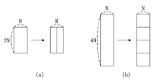
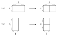
16 is a view showing an example of vertical partitioning and horizontal partitioning.
17 is a diagram illustrating an example of determining a division type of a coding block.
18 is a diagram illustrating an example of determining a division type of a coding block.
19 is a diagram illustrating an example in which a division type of a coding block is determined based on an intra prediction mode of the coding block.
20 is a diagram for explaining a splitting aspect of a coding block.
21 is a diagram illustrating an example in which a prediction encoding mode is set differently for each sub-block.
22 is a view showing an application aspect of PDPC.
23 and 24 are diagrams illustrating sub-blocks in which the second transform is to be performed.
25 is a diagram for explaining an example in which a conversion type of a current block is determined.
26 is a diagram illustrating an example of determining a conversion type of a sub-block.
27 is a view for explaining an example in which the residual coefficients of the sub-blocks are set to zero.
28 shows an example in which the location of a sub-block in which transformation and / or quantization has been performed is specified based on information signaled through a bitstream.
29 is a flowchart illustrating a process for determining block strength.
30 shows predefined filter candidates.
이하에서는 도면을 참조하여 본 발명의 실시예를 상세히 설명한다.Hereinafter, embodiments of the present invention will be described in detail with reference to the drawings.
영상의 부호화 및 복호화는 블록 단위로 수행된다. 일 예로, 코딩 블록, 변환 블록, 또는 예측 블록에 대해, 변환, 양자화, 예측, 인루프 필터링, 또는 복원 등의 부호화/복호화 처리가 수행될 수 있다. Encoding and decoding of an image is performed in block units. For example, encoding / decoding processing such as transformation, quantization, prediction, in-loop filtering, or reconstruction may be performed on a coding block, a transform block, or a prediction block.
이하, 부호화/복호화 대상인 블록을 '현재 블록'이라 호칭하기로 한다. 일 예로, 현재 블록은 현재 부호화/복호화 처리 단계에 따라, 코딩 블록, 변환 블록, 또는 예측 블록을 나타낼 수 있다.Hereinafter, a block to be encoded / decoded will be referred to as a 'current block'. For example, the current block may represent a coding block, a transform block, or a prediction block according to the current encoding / decoding process step.
아울러, 본 명세서에서 사용되는 용어 '유닛'은 특정 부호화/복호화 프로세스를 수행하기 위한 기본 단위를 나타내고, '블록'은 소정 크기의 샘플 어레이를 나타내는 것으로 이해될 수 있다. 별도의 설명이 없는 한, '블록'과 '유닛'은 동등한 의미로 사용될 수 있다. 일 예로, 후술되는 실시예에서, 코딩 블록과 코딩 유닛은 상호 동등한 의미를 갖는 것으로 이해될 수 있다. In addition, the term 'unit' as used herein may be understood to indicate a basic unit for performing a specific encoding / decoding process, and 'block' indicating a sample array of a predetermined size. Unless otherwise specified, 'block' and 'unit' may be used interchangeably. For example, in the embodiments described below, it may be understood that the coding block and the coding unit have mutually equivalent meanings.
도 1은 본 발명의 일 실시예에 따른 영상 부호화기(인코더기)의 블록도이다.1 is a block diagram of an image encoder (encoder) according to an embodiment of the present invention.
도 1을 참조하면, 영상 부호화 장치(100)는 픽쳐 분할부(110), 예측부(120, 125), 변환부(130), 양자화부(135), 재정렬부(160), 엔트로피 부호화부(165), 역양자화부(140), 역변환부(145), 필터부(150) 및 메모리(155)를 포함할 수 있다.Referring to FIG. 1, the image encoding apparatus 100 includes a
도 1에 나타난 각 구성부들은 영상 부호화 장치에서 서로 다른 특징적인 기능들을 나타내기 위해 독립적으로 도시한 것으로, 각 구성부들이 분리된 하드웨어나 하나의 소프트웨어 구성단위로 이루어짐을 의미하지 않는다. 즉, 각 구성부는 설명의 편의상 각각의 구성부로 나열하여 포함한 것으로 각 구성부 중 적어도 두 개의 구성부가 합쳐져 하나의 구성부로 이루어지거나, 하나의 구성부가 복수개의 구성부로 나뉘어져 기능을 수행할 수 있고 이러한 각 구성부의 통합된 실시예 및 분리된 실시예도 본 발명의 본질에서 벗어나지 않는 한 본 발명의 권리범위에 포함된다.Each component shown in FIG. 1 is independently illustrated to represent different characteristic functions in the image encoding apparatus, and does not mean that each component is composed of separate hardware or a single software component. That is, for convenience of description, each component is listed and included as each component, and at least two components of each component are combined to form one component, or one component is divided into a plurality of components to perform functions. The integrated and separated embodiments of the components are also included in the scope of the present invention without departing from the essence of the present invention.
또한, 일부의 구성 요소는 본 발명에서 본질적인 기능을 수행하는 필수적인 구성 요소는 아니고 단지 성능을 향상시키기 위한 선택적 구성 요소일 수 있다. 본 발명은 단지 성능 향상을 위해 사용되는 구성 요소를 제외한 본 발명의 본질을 구현하는데 필수적인 구성부만을 포함하여 구현될 수 있고, 단지 성능 향상을 위해 사용되는 선택적 구성 요소를 제외한 필수 구성 요소만을 포함한 구조도 본 발명의 권리범위에 포함된다.Also, some of the components are not essential components for performing essential functions in the present invention, but may be optional components for improving performance. The present invention can be implemented by including only components essential for realizing the essence of the present invention, except components used for performance improvement, and structures including only essential components excluding optional components used for performance improvement. Also included in the scope of the present invention.
픽쳐 분할부(110)는 입력된 픽쳐를 적어도 하나의 처리 단위로 분할할 수 있다. 이때, 처리 단위는 예측 단위(Prediction Unit: PU)일 수도 있고, 변환 단위(Transform Unit: TU)일 수도 있으며, 부호화 단위(Coding Unit: CU)일 수도 있다. 픽쳐 분할부(110)에서는 하나의 픽쳐에 대해 복수의 부호화 단위, 예측 단위 및 변환 단위의 조합으로 분할하고 소정의 기준(예를 들어, 비용 함수)으로 하나의 부호화 단위, 예측 단위 및 변환 단위 조합을 선택하여 픽쳐를 부호화 할 수 있다.The
예를 들어, 하나의 픽쳐는 복수개의 부호화 단위로 분할될 수 있다. 픽쳐에서 부호화 단위를 분할하기 위해서는 쿼드 트리 구조(Quad Tree Structure)와 같은 재귀적인 트리 구조를 사용할 수 있는데 하나의 영상 또는 최대 크기 부호화 단위(largest coding unit)를 루트로 하여 다른 부호화 단위로 분할되는 부호화 유닛은 분할된 부호화 단위의 개수만큼의 자식 노드를 가지고 분할될 수 있다. 일정한 제한에 따라 더 이상 분할되지 않는 부호화 단위는 리프 노드가 된다. 즉, 하나의 코딩 유닛에 대하여 정방형 분할만이 가능하다고 가정하는 경우, 하나의 부호화 단위는 최대 4개의 다른 부호화 단위로 분할될 수 있다.For example, one picture may be divided into a plurality of coding units. In order to split a coding unit in a picture, a recursive tree structure such as a quad tree structure can be used. One image or a coding that is split into another coding unit using a largest coding unit as a root The unit may be divided into as many child nodes as the number of divided coding units. According to a certain restriction, a coding unit that is no longer split is a leaf node. That is, when it is assumed that only square division is possible for one coding unit, one coding unit may be divided into up to four different coding units.
이하, 본 발명의 실시예에서는 부호화 단위는 부호화를 수행하는 단위의 의미로 사용할 수도 있고, 복호화를 수행하는 단위의 의미로 사용할 수도 있다.Hereinafter, in an embodiment of the present invention, a coding unit may be used as a meaning of a unit that performs coding or may be used as a meaning of a unit that performs decoding.
예측 단위는 하나의 부호화 단위 내에서 동일한 크기의 적어도 하나의 정사각형 또는 직사각형 등의 형태를 가지고 분할된 것일 수도 있고, 하나의 부호화 단위 내에서 분할된 예측 단위 중 어느 하나의 예측 단위가 다른 하나의 예측 단위와 상이한 형태 및/또는 크기를 가지도록 분할된 것일 수도 있다.The prediction unit may be divided into at least one square or rectangular shape having the same size within one coding unit, and one prediction unit among the prediction units split within one coding unit may be another prediction unit. It may be divided into units having different shapes and / or sizes.
부호화 단위를 기초로 인트라 예측을 수행하는 예측 단위를 생성시 최소 부호화 단위가 아닌 경우, 복수의 예측 단위 NxN 으로 분할하지 않고 인트라 예측을 수행할 수 있다.When a prediction unit that performs intra prediction based on a coding unit is not a minimum coding unit, intra prediction may be performed without splitting into a plurality of prediction units NxN.
예측부(120, 125)는 인터 예측을 수행하는 인터 예측부(120)와 인트라 예측을 수행하는 인트라 예측부(125)를 포함할 수 있다. 예측 단위에 대해 인터 예측을 사용할 것인지 또는 인트라 예측을 수행할 것인지를 결정하고, 각 예측 방법에 따른 구체적인 정보(예컨대, 인트라 예측 모드, 모션 벡터, 참조 픽쳐 등)를 결정할 수 있다. 이때, 예측이 수행되는 처리 단위와 예측 방법 및 구체적인 내용이 정해지는 처리 단위는 다를 수 있다. 예컨대, 예측의 방법과 예측 모드 등은 예측 단위로 결정되고, 예측의 수행은 변환 단위로 수행될 수도 있다. 생성된 예측 블록과 원본 블록 사이의 잔차값(잔차 블록)은 변환부(130)로 입력될 수 있다. 또한, 예측을 위해 사용한 예측 모드 정보, 모션 벡터 정보 등은 잔차값과 함께 엔트로피 부호화부(165)에서 부호화되어 복호화기에 전달될 수 있다. 특정한 부호화 모드를 사용할 경우, 예측부(120, 125)를 통해 예측 블록을 생성하지 않고, 원본 블록을 그대로 부호화하여 복호화부에 전송하는 것도 가능하다.The
인터 예측부(120)는 현재 픽쳐의 이전 픽쳐 또는 이후 픽쳐 중 적어도 하나의 픽쳐의 정보를 기초로 예측 단위를 예측할 수도 있고, 경우에 따라서는 현재 픽쳐 내의 부호화가 완료된 일부 영역의 정보를 기초로 예측 단위를 예측할 수도 있다. 인터 예측부(120)는 참조 픽쳐 보간부, 모션 예측부, 움직임 보상부를 포함할 수 있다. The
참조 픽쳐 보간부에서는 메모리(155)로부터 참조 픽쳐 정보를 제공받고 참조 픽쳐에서 정수 화소 이하의 화소 정보를 생성할 수 있다. 휘도 화소의 경우, 1/4 화소 단위로 정수 화소 이하의 화소 정보를 생성하기 위해 필터 계수를 달리하는 DCT 기반의 8탭 보간 필터(DCT-based Interpolation Filter)가 사용될 수 있다. 색차 신호의 경우 1/8 화소 단위로 정수 화소 이하의 화소 정보를 생성하기 위해 필터 계수를 달리하는 DCT 기반의 4탭 보간 필터(DCT-based Interpolation Filter)가 사용될 수 있다.The reference picture interpolator may receive reference picture information from the
모션 예측부는 참조 픽쳐 보간부에 의해 보간된 참조 픽쳐를 기초로 모션 예측을 수행할 수 있다. 모션 벡터를 산출하기 위한 방법으로 FBMA(Full search-based Block Matching Algorithm), TSS(Three Step Search), NTS(New Three-Step Search Algorithm) 등 다양한 방법이 사용될 수 있다. 모션 벡터는 보간된 화소를 기초로 1/2 또는 1/4 화소 단위의 모션 벡터값을 가질 수 있다. 모션 예측부에서는 모션 예측 방법을 다르게 하여 현재 예측 단위를 예측할 수 있다. 모션 예측 방법으로 스킵(Skip) 방법, 머지(Merge) 방법, AMVP(Advanced Motion Vector Prediction) 방법, 인트라 블록 카피(Intra Block Copy) 방법 등 다양한 방법이 사용될 수 있다.The motion prediction unit may perform motion prediction based on the reference picture interpolated by the reference picture interpolation unit. As a method for calculating the motion vector, various methods such as Full Search-based Block Matching Algorithm (FBMA), Three Step Search (TSS), and New Three-Step Search Algorithm (NTS) can be used. The motion vector may have a motion vector value in units of 1/2 or 1/4 pixels based on the interpolated pixels. The motion prediction unit may predict the current prediction unit by differently using a motion prediction method. As a motion prediction method, various methods such as a skip method, a merge method, an AMVP (Advanced Motion Vector Prediction) method, and an intra block copy method may be used.
인트라 예측부(125)는 현재 픽쳐 내의 화소 정보인 현재 블록 주변의 참조 픽셀 정보를 기초로 예측 단위를 생성할 수 있다. 현재 예측 단위의 주변 블록이 인터 예측을 수행한 블록이어서, 참조 픽셀이 인터 예측을 수행한 픽셀일 경우, 인터 예측을 수행한 블록에 포함되는 참조 픽셀을 주변의 인트라 예측을 수행한 블록의 참조 픽셀 정보로 대체하여 사용할 수 있다. 즉, 참조 픽셀이 가용하지 않는 경우, 가용하지 않은 참조 픽셀 정보를 가용한 참조 픽셀 중 적어도 하나의 참조 픽셀로 대체하여 사용할 수 있다.The
인트라 예측에서 예측 모드는 참조 픽셀 정보를 예측 방향에 따라 사용하는 방향성 예측 모드와 예측을 수행시 방향성 정보를 사용하지 않는 비방향성 모드를 가질 수 있다. 휘도 정보를 예측하기 위한 모드와 색차 정보를 예측하기 위한 모드가 상이할 수 있고, 색차 정보를 예측하기 위해 휘도 정보를 예측하기 위해 사용된 인트라 예측 모드 정보 또는 예측된 휘도 신호 정보를 활용할 수 있다.In intra prediction, the prediction mode may have a directional prediction mode that uses reference pixel information according to a prediction direction and a non-directional mode that does not use directional information when performing prediction. A mode for predicting luminance information and a mode for predicting color difference information may be different, and intra prediction mode information or predicted luminance signal information used for predicting luminance information may be used to predict color difference information.
인트라 예측을 수행할 때 예측 단위의 크기와 변환 단위의 크기가 동일할 경우, 예측 단위의 좌측에 존재하는 픽셀, 좌측 상단에 존재하는 픽셀, 상단에 존재하는 픽셀을 기초로 예측 단위에 대한 인트라 예측을 수행할 수 있다. 그러나 인트라 예측을 수행할 때 예측 단위의 크기와 변환 단위의 크기가 상이할 경우, 변환 단위를 기초로 한 참조 픽셀을 이용하여 인트라 예측을 수행할 수 있다. 또한, 최소 부호화 단위에 대해서만 NxN 분할을 사용하는 인트라 예측을 사용할 수 있다.When performing the intra prediction, if the size of the prediction unit and the size of the transformation unit are the same, intra prediction for the prediction unit based on the pixel located on the left of the prediction unit, the pixel on the top left, and the pixel on the top of the prediction unit You can do However, when the size of the prediction unit and the size of the transformation unit are different when performing intra prediction, intra prediction may be performed using a reference pixel based on the transformation unit. In addition, intra prediction using NxN splitting can be used only for a minimum coding unit.
인트라 예측 방법은 예측 모드에 따라 참조 화소에 AIS(Adaptive Intra Smoothing) 필터를 적용한 후 예측 블록을 생성할 수 있다. 참조 화소에 적용되는 AIS 필터의 종류는 상이할 수 있다. 인트라 예측 방법을 수행하기 위해 현재 예측 단위의 인트라 예측 모드는 현재 예측 단위의 주변에 존재하는 예측 단위의 인트라 예측 모드로부터 예측할 수 있다. 주변 예측 단위로부터 예측된 모드 정보를 이용하여 현재 예측 단위의 예측 모드를 예측하는 경우, 현재 예측 단위와 주변 예측 단위의 인트라 예측 모드가 동일하면 소정의 플래그 정보를 이용하여 현재 예측 단위와 주변 예측 단위의 예측 모드가 동일하다는 정보를 전송할 수 있고, 만약 현재 예측 단위와 주변 예측 단위의 예측 모드가 상이하면 엔트로피 부호화를 수행하여 현재 블록의 예측 모드 정보를 부호화할 수 있다.The intra prediction method may generate a prediction block after applying an adaptive intra smoothing (AIS) filter to the reference pixel according to the prediction mode. The type of AIS filter applied to the reference pixel may be different. In order to perform the intra prediction method, the intra prediction mode of the current prediction unit may be predicted from the intra prediction mode of the prediction unit existing around the current prediction unit. When the prediction mode of the current prediction unit is predicted using the mode information predicted from the neighboring prediction unit, if the intra prediction mode of the current prediction unit and the neighboring prediction unit are the same, the current prediction unit and the neighboring prediction unit using predetermined flag information It is possible to transmit the information that the prediction mode of is the same, and if the prediction mode of the current prediction unit and the neighboring prediction unit are different, entropy encoding may be performed to encode the prediction mode information of the current block.
또한, 예측부(120, 125)에서 생성된 예측 단위를 기초로 예측을 수행한 예측 단위와 예측 단위의 원본 블록과 차이값인 잔차값(Residual) 정보를 포함하는 잔차 블록이 생성될 수 있다. 생성된 잔차 블록은 변환부(130)로 입력될 수 있다. In addition, a residual block including prediction unit performing prediction based on the prediction unit generated by the
변환부(130)에서는 원본 블록과 예측부(120, 125)를 통해 생성된 예측 단위의 잔차값(residual)정보를 포함한 잔차 블록을 DCT(Discrete Cosine Transform), DST(Discrete Sine Transform), KLT와 같은 변환 방법을 사용하여 변환시킬 수 있다. 잔차 블록을 변환하기 위해 DCT를 적용할지, DST를 적용할지 또는 KLT를 적용할지는 잔차 블록을 생성하기 위해 사용된 예측 단위의 인트라 예측 모드 정보를 기초로 결정할 수 있다. The
양자화부(135)는 변환부(130)에서 주파수 영역으로 변환된 값들을 양자화할 수 있다. 블록에 따라 또는 영상의 중요도에 따라 양자화 계수는 변할 수 있다. 양자화부(135)에서 산출된 값은 역양자화부(140)와 재정렬부(160)에 제공될 수 있다.The
재정렬부(160)는 양자화된 잔차값에 대해 계수값의 재정렬을 수행할 수 있다.The
재정렬부(160)는 계수 스캐닝(Coefficient Scanning) 방법을 통해 2차원의 블록 형태 계수를 1차원의 벡터 형태로 변경할 수 있다. 예를 들어, 재정렬부(160)에서는 지그-재그 스캔(Zig-Zag Scan)방법을 이용하여 DC 계수부터 고주파수 영역의 계수까지 스캔하여 1차원 벡터 형태로 변경시킬 수 있다. 변환 단위의 크기 및 인트라 예측 모드에 따라 지그-재그 스캔 대신 2차원의 블록 형태 계수를 열 방향으로 스캔하는 수직 스캔, 2차원의 블록 형태 계수를 행 방향으로 스캔하는 수평 스캔이 사용될 수도 있다. 즉, 변환 단위의 크기 및 인트라 예측 모드에 따라 지그-재그 스캔, 수직 방향 스캔 및 수평 방향 스캔 중 어떠한 스캔 방법이 사용될지 여부를 결정할 수 있다.The
엔트로피 부호화부(165)는 재정렬부(160)에 의해 산출된 값들을 기초로 엔트로피 부호화를 수행할 수 있다. 엔트로피 부호화는 예를 들어, 지수 골롬(Exponential Golomb), CAVLC(Context-Adaptive Variable Length Coding), CABAC(Context-Adaptive Binary Arithmetic Coding)과 같은 다양한 부호화 방법을 사용할 수 있다. The
엔트로피 부호화부(165)는 재정렬부(160) 및 예측부(120, 125)로부터 부호화 단위의 잔차값 계수 정보 및 블록 타입 정보, 예측 모드 정보, 분할 단위 정보, 예측 단위 정보 및 전송 단위 정보, 모션 벡터 정보, 참조 프레임 정보, 블록의 보간 정보, 필터링 정보 등 다양한 정보를 부호화할 수 있다. The
엔트로피 부호화부(165)에서는 재정렬부(160)에서 입력된 부호화 단위의 계수값을 엔트로피 부호화할 수 있다.The
역양자화부(140) 및 역변환부(145)에서는 양자화부(135)에서 양자화된 값들을 역양자화하고 변환부(130)에서 변환된 값들을 역변환한다. 역양자화부(140) 및 역변환부(145)에서 생성된 잔차값(Residual)은 예측부(120, 125)에 포함된 움직임 추정부, 움직임 보상부 및 인트라 예측부를 통해서 예측된 예측 단위와 합쳐져 복원 블록(Reconstructed Block)을 생성할 수 있다. The
필터부(150)는 디블록킹 필터, 오프셋 보정부, ALF(Adaptive Loop Filter)중 적어도 하나를 포함할 수 있다.The
디블록킹 필터는 복원된 픽쳐에서 블록간의 경계로 인해 생긴 블록 왜곡을 제거할 수 있다. 디블록킹을 수행할지 여부를 판단하기 위해 블록에 포함된 몇 개의 열 또는 행에 포함된 픽셀을 기초로 현재 블록에 디블록킹 필터 적용할지 여부를 판단할 수 있다. 블록에 디블록킹 필터를 적용하는 경우 필요한 디블록킹 필터링 강도에 따라 강한 필터(Strong Filter) 또는 약한 필터(Weak Filter)를 적용할 수 있다. 또한 디블록킹 필터를 적용함에 있어 수직 필터링 및 수평 필터링 수행시 수평 방향 필터링 및 수직 방향 필터링이 병행 처리되도록 할 수 있다.The deblocking filter can remove block distortion caused by boundary between blocks in the reconstructed picture. In order to determine whether to perform deblocking, it may be determined whether to apply a deblocking filter to the current block based on pixels included in a few columns or rows included in the block. When a deblocking filter is applied to a block, a strong filter or a weak filter may be applied according to the required deblocking filtering strength. In addition, in applying the deblocking filter, when performing vertical filtering and horizontal filtering, horizontal filtering and vertical filtering may be processed in parallel.
오프셋 보정부는 디블록킹을 수행한 영상에 대해 픽셀 단위로 원본 영상과의 오프셋을 보정할 수 있다. 특정 픽쳐에 대한 오프셋 보정을 수행하기 위해 영상에 포함된 픽셀을 일정한 수의 영역으로 구분한 후 오프셋을 수행할 영역을 결정하고 해당 영역에 오프셋을 적용하는 방법 또는 각 픽셀의 에지 정보를 고려하여 오프셋을 적용하는 방법을 사용할 수 있다.The offset correction unit may correct an offset from the original image in units of pixels for the deblocking image. In order to perform offset correction for a specific picture, after dividing the pixels included in the image into a certain number of regions, determining the region to perform the offset and applying the offset to the region, or offset by considering the edge information of each pixel You can use the method of applying.
ALF(Adaptive Loop Filtering)는 필터링한 복원 영상과 원래의 영상을 비교한 값을 기초로 수행될 수 있다. 영상에 포함된 픽셀을 소정의 그룹으로 나눈 후 해당 그룹에 적용될 하나의 필터를 결정하여 그룹마다 차별적으로 필터링을 수행할 수 있다. ALF를 적용할지 여부에 관련된 정보는 휘도 신호는 부호화 단위(Coding Unit, CU) 별로 전송될 수 있고, 각각의 블록에 따라 적용될 ALF 필터의 모양 및 필터 계수는 달라질 수 있다. 또한, 적용 대상 블록의 특성에 상관없이 동일한 형태(고정된 형태)의 ALF 필터가 적용될 수도 있다. ALF (Adaptive Loop Filtering) may be performed based on a value obtained by comparing a filtered reconstructed image with an original image. After dividing the pixels included in the image into a predetermined group, one filter to be applied to the corresponding group may be determined to perform filtering differently for each group. For information related to whether to apply ALF, the luminance signal may be transmitted for each coding unit (CU), and the shape and filter coefficient of the ALF filter to be applied may be changed according to each block. Also, the ALF filter of the same form (fixed form) may be applied regardless of the characteristics of the block to be applied.
메모리(155)는 필터부(150)를 통해 산출된 복원 블록 또는 픽쳐를 저장할 수 있고, 저장된 복원 블록 또는 픽쳐는 인터 예측을 수행 시 예측부(120, 125)에 제공될 수 있다.The
도 2는 본 발명의 일 실시예에 따른 영상 복호화기(디코더기)의 블록도이다.2 is a block diagram of an image decoder (decoder) according to an embodiment of the present invention.
도 2를 참조하면, 영상 복호화기(200)는 엔트로피 복호화부(210), 재정렬부(215), 역양자화부(220), 역변환부(225), 예측부(230, 235), 필터부(240), 메모리(245)가 포함될 수 있다.Referring to FIG. 2, the image decoder 200 includes an
영상 부호화기에서 영상 비트스트림이 입력된 경우, 입력된 비트스트림은 영상 부호화기와 반대의 절차로 복호화될 수 있다.When an image bitstream is input from the image encoder, the input bitstream may be decoded in a procedure opposite to that of the image encoder.
엔트로피 복호화부(210)는 영상 부호화기의 엔트로피 부호화부에서 엔트로피 부호화를 수행한 것과 반대의 절차로 엔트로피 복호화를 수행할 수 있다. 예를 들어, 영상 부호화기에서 수행된 방법에 대응하여 지수 골롬(Exponential Golomb), CAVLC(Context-Adaptive Variable Length Coding), CABAC(Context-Adaptive Binary Arithmetic Coding)과 같은 다양한 방법이 적용될 수 있다. The
엔트로피 복호화부(210)에서는 부호화기에서 수행된 인트라 예측 및 인터 예측에 관련된 정보를 복호화할 수 있다.The
재정렬부(215)는 엔트로피 복호화부(210)에서 엔트로피 복호화된 비트스트림을 부호화부에서 재정렬한 방법을 기초로 재정렬을 수행할 수 있다. 1차원 벡터 형태로 표현된 계수들을 다시 2차원의 블록 형태의 계수로 복원하여 재정렬할 수 있다. 재정렬부(215)에서는 부호화부에서 수행된 계수 스캐닝에 관련된 정보를 제공받고 해당 부호화부에서 수행된 스캐닝 순서에 기초하여 역으로 스캐닝하는 방법을 통해 재정렬을 수행할 수 있다.The
역양자화부(220)는 부호화기에서 제공된 양자화 파라미터와 재정렬된 블록의 계수값을 기초로 역양자화를 수행할 수 있다. The
역변환부(225)는 영상 부호화기에서 수행한 양자화 결과에 대해 변환부에서 수행한 변환 즉, DCT, DST, 및 KLT에 대해 역변환 즉, 역 DCT, 역 DST 및 역 KLT를 수행할 수 있다. 역변환은 영상 부호화기에서 결정된 전송 단위를 기초로 수행될 수 있다. 영상 복호화기의 역변환부(225)에서는 예측 방법, 현재 블록의 크기 및 예측 방향 등 복수의 정보에 따라 변환 기법(예를 들어, DCT, DST, KLT)이 선택적으로 수행될 수 있다.The
예측부(230, 235)는 엔트로피 복호화부(210)에서 제공된 예측 블록 생성 관련 정보와 메모리(245)에서 제공된 이전에 복호화된 블록 또는 픽쳐 정보를 기초로 예측 블록을 생성할 수 있다. The
전술한 바와 같이 영상 부호화기에서의 동작과 동일하게 인트라 예측을 수행시 예측 단위의 크기와 변환 단위의 크기가 동일할 경우, 예측 단위의 좌측에 존재하는 픽셀, 좌측 상단에 존재하는 픽셀, 상단에 존재하는 픽셀을 기초로 예측 단위에 대한 인트라 예측을 수행하지만, 인트라 예측을 수행시 예측 단위의 크기와 변환 단위의 크기가 상이할 경우, 변환 단위를 기초로 한 참조 픽셀을 이용하여 인트라 예측을 수행할 수 있다. 또한, 최소 부호화 단위에 대해서만 NxN 분할을 사용하는 인트라 예측을 사용할 수도 있다.As described above, when intra prediction is performed in the same manner as in the image encoder, when the size of the prediction unit and the size of the transformation unit are the same, the pixels located on the left side of the prediction unit, the pixels located on the upper left, and the top level are present. Intra prediction of the prediction unit is performed based on the pixel, but when the size of the prediction unit and the size of the transformation unit are different when performing the intra prediction, intra prediction is performed using the reference pixel based on the transformation unit. You can. In addition, intra prediction using NxN splitting may be used only for the smallest coding unit.
예측부(230, 235)는 예측 단위 판별부, 인터 예측부 및 인트라 예측부를 포함할 수 있다. 예측 단위 판별부는 엔트로피 복호화부(210)에서 입력되는 예측 단위 정보, 인트라 예측 방법의 예측 모드 정보, 인터 예측 방법의 모션 예측 관련 정보 등 다양한 정보를 입력 받고 현재 부호화 단위에서 예측 단위를 구분하고, 예측 단위가 인터 예측을 수행하는지 아니면 인트라 예측을 수행하는지 여부를 판별할 수 있다. 인터 예측부(230)는 영상 부호화기에서 제공된 현재 예측 단위의 인터 예측에 필요한 정보를 이용해 현재 예측 단위가 포함된 현재 픽쳐의 이전 픽쳐 또는 이후 픽쳐 중 적어도 하나의 픽쳐에 포함된 정보를 기초로 현재 예측 단위에 대한 인터 예측을 수행할 수 있다. 또는, 현재 예측 단위가 포함된 현재 픽쳐 내에서 기-복원된 일부 영역의 정보를 기초로 인터 예측을 수행할 수도 있다.The
인터 예측을 수행하기 위해 부호화 단위를 기준으로 해당 부호화 단위에 포함된 예측 단위의 모션 예측 방법이 스킵 모드(Skip Mode), 머지 모드(Merge 모드), 모션 벡터 예측 모드(AMVP Mode), 인트라 블록 카피 모드 중 어떠한 방법인지 여부를 판단할 수 있다.In order to perform inter prediction, a motion prediction method of a prediction unit included in a corresponding coding unit based on a coding unit is a skip mode, a merge mode, a motion vector prediction mode (AMVP mode), and an intra block copy It can be determined whether it is any of the modes.
인트라 예측부(235)는 현재 픽쳐 내의 화소 정보를 기초로 예측 블록을 생성할 수 있다. 예측 단위가 인트라 예측을 수행한 예측 단위인 경우, 영상 부호화기에서 제공된 예측 단위의 인트라 예측 모드 정보를 기초로 인트라 예측을 수행할 수 있다. 인트라 예측부(235)에는 AIS(Adaptive Intra Smoothing) 필터, 참조 화소 보간부, DC 필터를 포함할 수 있다. AIS 필터는 현재 블록의 참조 화소에 필터링을 수행하는 부분으로써 현재 예측 단위의 예측 모드에 따라 필터의 적용 여부를 결정하여 적용할 수 있다. 영상 부호화기에서 제공된 예측 단위의 예측 모드 및 AIS 필터 정보를 이용하여 현재 블록의 참조 화소에 AIS 필터링을 수행할 수 있다. 현재 블록의 예측 모드가 AIS 필터링을 수행하지 않는 모드일 경우, AIS 필터는 적용되지 않을 수 있다.The
참조 화소 보간부는 예측 단위의 예측 모드가 참조 화소를 보간한 화소값을 기초로 인트라 예측을 수행하는 예측 단위일 경우, 참조 화소를 보간하여 정수값 이하의 화소 단위의 참조 화소를 생성할 수 있다. 현재 예측 단위의 예측 모드가 참조 화소를 보간하지 않고 예측 블록을 생성하는 예측 모드일 경우 참조 화소는 보간되지 않을 수 있다. DC 필터는 현재 블록의 예측 모드가 DC 모드일 경우 필터링을 통해서 예측 블록을 생성할 수 있다.When the prediction mode of the prediction unit is a prediction unit that performs intra prediction based on a pixel value obtained by interpolating a reference pixel, the reference pixel interpolation unit may interpolate the reference pixel to generate a pixel reference pixel in an integer value or less. If the prediction mode of the current prediction unit is a prediction mode that generates a prediction block without interpolating a reference pixel, the reference pixel may not be interpolated. The DC filter may generate a prediction block through filtering when the prediction mode of the current block is the DC mode.
복원된 블록 또는 픽쳐는 필터부(240)로 제공될 수 있다. 필터부(240)는 디블록킹 필터, 오프셋 보정부, ALF를 포함할 수 있다.The reconstructed block or picture may be provided to the
영상 부호화기로부터 해당 블록 또는 픽쳐에 디블록킹 필터를 적용하였는지 여부에 대한 정보 및 디블록킹 필터를 적용하였을 경우, 강한 필터를 적용하였는지 또는 약한 필터를 적용하였는지에 대한 정보를 제공받을 수 있다. 영상 복호화기의 디블록킹 필터에서는 영상 부호화기에서 제공된 디블록킹 필터 관련 정보를 제공받고 영상 복호화기에서 해당 블록에 대한 디블록킹 필터링을 수행할 수 있다. Information about whether a deblocking filter is applied to a corresponding block or picture and information about whether a strong filter is applied or a weak filter is applied may be provided from a video encoder. In the deblocking filter of the video decoder, information related to the deblocking filter provided by the video encoder may be provided, and the video decoder may perform deblocking filtering on the corresponding block.
오프셋 보정부는 부호화시 영상에 적용된 오프셋 보정의 종류 및 오프셋 값 정보 등을 기초로 복원된 영상에 오프셋 보정을 수행할 수 있다.The offset correction unit may perform offset correction on the reconstructed image based on the type of offset correction and offset value information applied to the image during encoding.
ALF는 부호화기로부터 제공된 ALF 적용 여부 정보, ALF 계수 정보 등을 기초로 부호화 단위에 적용될 수 있다. 이러한 ALF 정보는 특정한 파라메터 셋에 포함되어 제공될 수 있다.ALF may be applied to a coding unit based on ALF application information provided by an encoder, ALF coefficient information, and the like. Such ALF information may be provided by being included in a specific parameter set.
메모리(245)는 복원된 픽쳐 또는 블록을 저장하여 참조 픽쳐 또는 참조 블록으로 사용할 수 있도록 할 수 있고 또한 복원된 픽쳐를 출력부로 제공할 수 있다. The
도 3은 본 발명의 일 실시예에 따른 기본 코딩 트리 유닛을 도시한 도면이다.3 is a diagram illustrating a basic coding tree unit according to an embodiment of the present invention.
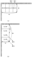
최대 크기의 코딩 블록을 코딩 트리 블록이라 정의할 수 있다. 하나의 픽처는 복수개의 코딩 트리 유닛(Coding Tree Unit, CTU)으로 분할된다. 코딩 트리 유닛은 최대 크기의 코딩 유닛으로, LCU (Largest Coding Unit)라 호칭될 수도 있다. 도 3은 하나의 픽처가 복수개의 코딩 트리 유닛으로 분할된 예를 나타낸 것이다.A maximum sized coding block can be defined as a coding tree block. One picture is divided into a plurality of coding tree units (CTUs). The coding tree unit is a coding unit having the largest size, and may be called a large coding unit (LCU). 3 shows an example in which one picture is divided into a plurality of coding tree units.
코딩 트리 유닛의 크기는 픽처 레벨 또는 시퀀스 레벨에서 정의될 수 있다. 이를 위해, 코딩 트리 유닛의 크기를 나타내는 정보가 픽처 파라미터 세트 또는 시퀀스 파라미터 세트를 통해 시그날링될 수 있다. The size of the coding tree unit can be defined at a picture level or a sequence level. To this end, information indicating the size of the coding tree unit may be signaled through a picture parameter set or a sequence parameter set.
일 예로, 시퀀스 내 전체 픽처에 대한 코딩 트리 유닛의 크기가 128x128로 설정될 수 있다. 또는, 픽처 레벨에서 128x128 또는 256x256 중 어느 하나를 코딩 트리 유닛의 크기로 결정할 수 있다. 일 예로, 제1 픽처에서는 코딩 트리 유닛의 크기가 128x128로 설정되고, 제2 픽처에서는 코딩 트리 유닛의 크기가 256x256으로 설정될 수 있다. For example, the size of a coding tree unit for all pictures in a sequence may be set to 128x128. Alternatively, one of 128x128 or 256x256 may be determined as a size of a coding tree unit at a picture level. For example, the size of the coding tree unit may be set to 128x128 in the first picture, and the size of the coding tree unit may be set to 256x256 in the second picture.
코딩 트리 유닛을 분할하여, 코딩 블록을 생성할 수 있다. 코딩 블록은 부호화/복호화 처리를 위한 기본 단위를 나타낸다. 일 예로, 코딩 블록 별로 예측 또는 변환이 수행되거나, 코딩 블록 별로 예측 부호화 모드가 결정될 수 있다. 여기서, 예측 부호화 모드는 예측 영상을 생성하는 방법을 나타낸다. 일 예로, 예측 부호화 모드는 화면 내 예측(Intra Prediction, 인트라 예측), 화면 간 예측(Inter Prediction, 인터 예측), 현재 픽처 참조(Current Picture Referencing, CPR, 또는 인트라 블록 카피(Intra Block Copy, IBC)) 또는 복합 예측(Combined Prediction)을 포함할 수 있다. 코딩 블록에 대해, 인트라 예측, 인터 예측, 현재 픽처 참조 또는 복합 예측 중 적어도 하나의 예측 부호화 모드를 이용하여, 코딩 블록에 대한 예측 블록을 생성할 수 있다. By dividing the coding tree unit, a coding block can be generated. The coding block represents a basic unit for encoding / decoding processing. For example, prediction or transformation may be performed for each coding block, or a prediction coding mode may be determined for each coding block. Here, the prediction encoding mode represents a method for generating a prediction image. For example, the prediction encoding mode includes intra prediction (Intra Prediction), inter prediction (Inter Prediction), current picture reference (Current Picture Referencing, CPR, or Intra Block Copy (IBC)). ) Or a combined prediction. For a coding block, a prediction block for a coding block may be generated using at least one prediction coding mode among intra prediction, inter prediction, current picture reference, or complex prediction.
현재 블록의 예측 부호화 모드를 나타내는 정보가 비트스트림을 통해 시그날링될 수 있다. 일 예로, 상기 정보는 예측 부호화 모드가 인트라 모드인지 또는 인터 모드인지 여부를 나타내는 1비트 플래그일 수 있다. 현재 블록의 예측 부호화 모드가 인터 모드로 결정된 경우에 한하여, 현재 픽처 참조 또는 복합 예측이 이용 가능할 수 있다. Information indicating a prediction encoding mode of a current block may be signaled through a bitstream. For example, the information may be a 1-bit flag indicating whether the prediction encoding mode is intra mode or inter mode. As long as the prediction encoding mode of the current block is determined as the inter mode, the current picture reference or composite prediction may be available.
현재 픽처 참조는 현재 픽처를 참조 픽처로 설정하고, 현재 픽처 내 이미 부호화/복호화가 완료된 영역으로부터 현재 블록의 예측 블록을 획득하기 위한 것이다. 여기서, 현재 픽처는 현재 블록을 포함하는 픽처를 의미한다. 현재 블록에 현재 픽처 참조가 적용되는지 여부를 나타내는 정보가 비트스트림을 통해 시그날링될 수 있다. 일 예로, 상기 정보는 1비트의 플래그일 수 있다. 상기 플래그가 참인 경우, 현재 블록의 예측 부호화 모드는 현재 픽처 참조로 결정되고, 상기 플래그가 거짓인 경우, 현재 블록의 예측 모드는 인터 예측으로 결정될 수 있다.The current picture reference is for setting a current picture as a reference picture and obtaining a prediction block of a current block from a region in which encoding / decoding has already been completed in the current picture. Here, the current picture means a picture including the current block. Information indicating whether a current picture reference is applied to a current block may be signaled through a bitstream. For example, the information may be a flag of 1 bit. When the flag is true, the prediction encoding mode of the current block is determined as a reference to the current picture, and when the flag is false, the prediction mode of the current block may be determined as inter prediction.
또는, 참조 픽처 인덱스를 기초로, 현재 블록의 예측 부호화 모드가 결정될 수 있다. 일 예로, 참조 픽처 인덱스가 현재 픽처를 가리키는 경우, 현재 블록의 예측 부호화 모드는 현재 픽처 참조로 결정될 수 있다. 참조 픽처 인덱스가 현재 픽처가 아닌 다른 픽처를 가리키는 경우, 현재 블록의 예측 부호화 모드는 인터 예측으로 결정될 수 있다. 즉, 현재 픽처 참조는 현재 픽처 내 부호화/복호화가 완료된 영역의 정보를 이용한 예측 방법이고, 인터 예측은 부호화/복호화가 완료된 다른 픽처의 정보를 이용한 예측 방법이다.Alternatively, the prediction coding mode of the current block may be determined based on the reference picture index. For example, when the reference picture index indicates the current picture, the prediction coding mode of the current block may be determined as the current picture reference. When the reference picture index points to a picture other than the current picture, the prediction coding mode of the current block may be determined as inter prediction. That is, the current picture reference is a prediction method using information of a region in which encoding / decoding is completed in the current picture, and inter prediction is a prediction method using information of another picture in which encoding / decoding is completed.
복합 예측은 인트라 예측, 인터 예측 및 현재 픽처 참조 중 둘 이상을 조합된 부호화 모드를 나타낸다. 일 예로, 복합 예측이 적용되는 경우, 인트라 예측, 인터 예측 또는 현재 픽처 참조 중 어느 하나를 기초로 제1 예측 블록이 생성되고, 다른 하나를 기초로 제2 예측 블록이 생성될 수 있다. 제1 예측 블록 및 제2 예측 블록이 생성되면, 제1 예측 블록 및 제2 예측 블록의 평균 연산 또는 가중합 연산을 통해 최종 예측 블록이 생성될 수 있다. 복합 예측이 적용되는지 여부를 나타내는 정보가 비트스트림을 통해 시그날링될 수 있다. 상기 정보는 1비트의 플래그일 수 있다. The composite prediction represents a coding mode combining two or more of intra prediction, inter prediction, and current picture reference. For example, when composite prediction is applied, a first prediction block may be generated based on one of intra prediction, inter prediction, or current picture reference, and a second prediction block may be generated based on the other. When the first prediction block and the second prediction block are generated, a final prediction block may be generated through an average operation or a weighted sum operation of the first prediction block and the second prediction block. Information indicating whether the composite prediction is applied may be signaled through the bitstream. The information may be a flag of 1 bit.
도 4는 코딩 블록의 다양한 분할 형태를 나타낸 도면이다.4 is a diagram showing various division types of a coding block.
코딩 블록은 쿼드 트리 분할, 바이너리 트리 분할 또는 트리플 트리 분할을 기초로 복수의 코딩 블록들로 분할될 수 있다. 분할된 코딩 블록도 다시 쿼드 트리 분할, 바이터리 트리 분할 또는 트리플 트리 분할을 기초로 다시 복수의 코딩 블록들로 분할될 수 있다.The coding block may be divided into a plurality of coding blocks based on quad tree splitting, binary tree splitting, or triple tree splitting. The divided coding block may be further divided into a plurality of coding blocks based on quad tree splitting, binary tree splitting, or triple tree splitting.
쿼드 트리 분할은 현재 블록을 4개의 블록들로 분할하는 분할 기법을 나타낸다. 쿼드 트리 분할의 결과, 현재 블록은 4개의 정방 형태 파티션들로 분할될 수 있다 (도 4의 (a) 'SPLIT_QT' 참조).Quad tree splitting represents a splitting technique that splits the current block into four blocks. As a result of the quad tree partition, the current block can be divided into four square partitions (see (a) 'SPLIT_QT' in FIG. 4).
바이너리 트리 분할은 현재 블록을 2개의 블록들로 분할하는 분할 기법을 나타낸다. 수직 방향을 따라(즉, 현재 블록을 가로지르는 수직선을 이용) 현재 블록을 두개의 블록들로 분할하는 것을 수직 방향 바이너리 트리 분할이라 호칭할 수 있고, 수평 방향을 따라(즉, 현재 블록을 가로지르는 수평선을 이용) 현재 블록을 두개의 블록들로 분할하는 것을 수평 방향 바이너리 트리 분할이라 호칭할 수 있다. 바이너리 트리 분할 결과, 현재 블록은 2개의 비정방 형태 파티션들로 분할될 수 있다. 도 4의 (b) 'SPLIT_BT_VER'는 수직 방향 바이너리 트리 분할 결과를 나타낸 것이고, 도 4의 (c) 'SPLIT_BT_HOR'는 수평 방향 바이너리 트리 분할 결과를 나타낸 것이다. Binary tree splitting represents a splitting technique that splits the current block into two blocks. Dividing the current block into two blocks along a vertical direction (ie, using a vertical line across the current block) may be referred to as a vertical binary tree partition, and along a horizontal direction (ie, traversing the current block). Dividing the current block into two blocks using a horizontal line may be referred to as horizontal binary tree partitioning. As a result of dividing the binary tree, the current block can be divided into two non-square partitions. FIG. 4 (b) 'SPLIT_BT_VER' shows the vertical binary tree splitting result, and FIG. 4 (c) 'SPLIT_BT_HOR' shows the horizontal binary tree splitting result.
트리플 트리 분할은 현재 블록을 3개의 블록들로 분할하는 분할 기법을 나타낸다. 수직 방향을 따라(즉, 현재 블록을 가로지르는 두개의 수직선을 이용) 현재 블록을 세개의 블록들로 분할하는 것을 수직 방향 트리플 트리 분할이라 호칭할 수 있고, 수평 방향을 따라(즉, 현재 블록을 가로지르는 두개의 수평선을 이용) 현재 블록을 세개의 블록들로 분할하는 것을 수평 방향 트리플 트리 분할이라 호칭할 수 있다. 트리플 트리 분할 결과, 현재 블록은 3개의 비정방 형태 파티션들로 분할될 수 있다. 이때, 현재 블록의 중앙에 위치하는 파티션의 너비/높이는 다른 파티션들의 너비/높이 대비 2배일 수 있다. 도 4의 (d) 'SPLIT_TT_VER'는 수직 방향 트리플 트리 분할 결과를 나타낸 것이고, 도 4의 (e) 'SPLIT_TT_HOR'는 수평 방향 트리플 트리 분할 결과를 나타낸 것이다. Triple tree splitting represents a splitting technique that splits the current block into three blocks. Dividing the current block into three blocks along a vertical direction (ie, using two vertical lines across the current block) may be referred to as a vertical triple tree split, and along a horizontal direction (ie, the current block). Splitting the current block into three blocks using two horizontal horizontal lines) can be referred to as horizontal triple tree splitting. As a result of the triple tree partition, the current block may be divided into three non-square partitions. At this time, the width / height of the partition located in the center of the current block may be twice the width / height of the other partitions. 4 (d) 'SPLIT_TT_VER' shows the result of vertical triple tree splitting, and FIG. 4 (e) 'SPLIT_TT_HOR' shows the horizontal triple tree splitting result.
코딩 트리 유닛의 분할 횟수를 분할 깊이(Partitioning Depth)라 정의할 수 있다. 시퀀스 또는 픽처 레벨에서 코딩 트리 유닛의 최대 분할 깊이가 결정될 수 있다. 이에 따라, 시퀀스 또는 필처별로 코딩 트리 유닛의 최대 분할 깊이가 상이할 수 있다. The number of splitting of the coding tree unit may be defined as a partitioning depth. At the sequence or picture level, the maximum split depth of the coding tree unit can be determined. Accordingly, the maximum splitting depth of the coding tree unit may be different for each sequence or feature.
또는, 분할 기법들 각각에 대한 최대 분할 깊이를 개별적으로 결정할 수 있다. 일 예로, 쿼드 트리 분할이 허용되는 최대 분할 깊이는 바이너리 트리 분할 및/또는 트리플 트리 분할이 허용되는 최대 분할 깊이와 상이할 수 있다.Alternatively, the maximum splitting depth for each of the splitting techniques can be individually determined. For example, the maximum splitting depth allowed for quad tree splitting may be different from the maximum splitting depth allowed for binary tree splitting and / or triple tree splitting.
부호화기는 현재 블록의 분할 형태 또는 분할 깊이 중 적어도 하나를 나타내는 정보를 비트스트림을 통해 시그날링할 수 있다. 복호화기는 비트스트림으로부터 파싱되는 상기 정보에 기초하여 코딩 트리 유닛의 분할 형태 및 분할 깊이를 결정할 수 있다. The encoder may signal information indicating at least one of a split type or a split depth of a current block through a bitstream. The decoder can determine the division type and division depth of the coding tree unit based on the information parsed from the bitstream.
도 5는 코딩 트리 유닛의 분할 양상을 예시한 도면이다.5 is a diagram illustrating a splitting aspect of a coding tree unit.
쿼드 트리 분할, 바이너리 트리 분할 및/또는 트리플 트리 분할 등의 분할 기법을 이용하여 코딩 블록을 분할하는 것을 멀티 트리 분할(Multi Tree Partitioning)이라 호칭할 수 있다. Splitting a coding block using a splitting technique such as quad tree splitting, binary tree splitting, and / or triple tree splitting may be referred to as multi-tree partitioning.
코딩 블록에 멀티 트리 분할을 적용하여 생성되는 코딩 블록들을 하위 코딩 블록들이라 호칭할 수 있다. 코딩 블록의 분할 깊이가 k인 경우, 하위 코딩 블록들의 분할 깊이는 k+1로 설정된다. Coding blocks generated by applying multi-tree partitioning to coding blocks may be referred to as lower coding blocks. When the division depth of the coding block is k, the division depth of the lower coding blocks is set to k + 1.
반대로, 분할 깊이가 k+1인 코딩 블록들에 대해, 분할 깊이가 k인 코딩 블록을 상위 코딩 블록이라 호칭할 수 있다. Conversely, for coding blocks having a split depth of k + 1, a coding block having a split depth of k may be referred to as an upper coding block.
현재 코딩 블록의 분할 타입은 상위 코딩 블록의 분할 형태 또는 이웃 코딩 블록의 분할 타입 중 적어도 하나를 기초로 결정될 수 있다. 여기서, 이웃 코딩 블록은 현재 코딩 블록에 인접하는 것으로, 현재 코딩 블록의 상단 이웃 블록, 좌측 이웃 블록, 또는 좌측 상단 코너에 인접하는 이웃 블록 중 적어도 하나를 포함할 수 있다. 여기서, 분할 타입은, 쿼드 트리 분할 여부, 바이너리 트리 분할 여부, 바이너리 트리 분할 방향, 트리플 트리 분할 여부, 또는 트리플 트리 분할 방향 중 적어도 하나를 포함할 수 있다.The division type of the current coding block may be determined based on at least one of a division type of an upper coding block or a division type of a neighboring coding block. Here, the neighboring coding block is adjacent to the current coding block, and may include at least one of an upper neighboring block, a left neighboring block, or a neighboring block adjacent to the upper left corner of the current coding block. Here, the split type may include at least one of quad tree splitting, binary tree splitting, binary tree splitting, triple tree splitting, or triple tree splitting.
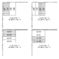
코딩 블록의 분할 형태를 결정하기 위해, 코딩 블록이 분할되는지 여부를 나타내는 정보가 비트스트림을 통해 시그날링될 수 있다. 상기 정보는 1비트의 플래그 'split_cu_flag'로, 상기 플래그가 참인 것은, 머리 트리 분할 기법에 의해 코딩 블록이 분할됨을 나타낸다.In order to determine a division type of a coding block, information indicating whether a coding block is divided may be signaled through a bitstream. The information is a 1-bit flag 'split_cu_flag', and the flag is true indicates that the coding block is split by the head tree splitting technique.
split_cu_flag가 참인 경우, 코딩 블록이 쿼드 트리 분할되는지 여부를 나타내는 정보가 비트스트림을 통해 시그날링될 수 있다. 상기 정보는 1비트의 플래그 split_qt_flag로, 상기 플래그가 참인 경우, 코딩 블록은 4개의 블록들로 분할될 수 있다.When split_cu_flag is true, information indicating whether a coding block is quad-tree split may be signaled through a bitstream. The information is a 1-bit flag split_qt_flag, and when the flag is true, a coding block may be divided into 4 blocks.
일 예로, 도 5에 도시된 예에서는, 코딩 트리 유닛이 쿼드 트리 분할됨에 따라, 분할 깊이가 1인 4개의 코딩 블록들이 생성되는 것으로 도시되었다. 또한, 쿼드 트리 분할 결과로 생성된 4개의 코딩 블록들 중 첫번째 코딩 블록 및 네번째 코딩 블록에 다시 쿼드 트리 분할이 적용된 것으로 도시되었다. 그 결과, 분할 깊이가 2인 4개의 코딩 블록들이 생성될 수 있다. As an example, in the example shown in FIG. 5, as the coding tree unit is quad-tree split, four coding blocks having a split depth of 1 are shown. Also, quad-tree splitting is again applied to the first coding block and the fourth coding block among the four coding blocks generated as a result of the quad-tree splitting. As a result, four coding blocks having a split depth of 2 can be generated.
또한, 분할 깊이가 2인 코딩 블록에 다시 쿼드 트리 분할을 적용함으로써, 분할 깊이가 3인 코딩 블록을 생성할 수 있다. Also, by applying quad-tree splitting again to a coding block having a split depth of 2, a coding block having a split depth of 3 may be generated.
코딩 블록에 쿼드 트리 분할이 적용되지 않는 경우, 코딩 블록의 크기, 코딩 블록이 픽처 경계에 위치하는지 여부, 최대 분할 깊이 또는 이웃 블록의 분할 형태 중 적어도 하나를 고려하여, 상기 코딩 블록에 바이너리 트리 분할 또는 트리플 트리 분할을 수행할 것인지 여부를 결정할 수 있다. 상기 코딩 블록에 바이너리 트리 분할 또는 트리플 트리 분할이 수행되는 것으로 결정된 경우, 분할 방향을 나타내는 정보가 비트스트림을 통해 시그날링될 수 있다. 상기 정보는 1비트의 플래그 mtt_split_cu_vertical_flag일 수 있다. 상기 플래그에 기초하여, 분할 방향이 수직 방향인지 또는 수평 방향인지 여부가 결정될 수 있다. 추가로, 바이너리 트리 분할 또는 트리플 트리 분할 중 어느 것이 상기 코딩 블록에 적용되는지를 나타내는 정보가 비트스트림을 통해 시그날링될 수 있다. 상기 정보는 1비트의 플래그 mtt_split_cu_binary_flag일 수 있다. 상기 플래그에 기초하여, 상기 코딩 블록에 바이너리 트리 분할이 적용되는지 또는 트리플 트리 분할이 적용되는지 여부가 결정될 수 있다.When quad-tree splitting is not applied to a coding block, binary tree splitting is performed on the coding block considering at least one of a size of a coding block, whether a coding block is located at a picture boundary, a maximum splitting depth, or a splitting form of neighboring blocks. Alternatively, it is possible to determine whether to perform triple tree splitting. When it is determined that the binary block or triple tree split is performed on the coding block, information indicating a split direction may be signaled through a bitstream. The information may be a 1-bit flag mtt_split_cu_vertical_flag. Based on the flag, it may be determined whether the dividing direction is a vertical direction or a horizontal direction. Additionally, information indicating whether binary tree splitting or triple tree splitting is applied to the coding block may be signaled through a bitstream. The information may be a 1-bit flag mtt_split_cu_binary_flag. Based on the flag, it may be determined whether binary tree splitting or triple tree splitting is applied to the coding block.
일 예로, 도 5에 도시된 예에서는, 분할 깊이 1인 코딩 블록에 수직 방향 바이너리 트리 분할이 적용되고, 상기 분할 결과로 생성된 코딩 블록들 중 좌측 코딩 블록에는 수직 방향 트리플 트리 분할이 적용되고, 우측 코딩 블록에는 수직 방향 바이너리 트리 분할이 적용된 것으로 도시되었다.For example, in the example illustrated in FIG. 5, vertical binary tree splitting is applied to a coding block having a split depth of 1, and vertical triple tree splitting is applied to a left coding block among coding blocks generated as a result of the splitting, The right coding block is illustrated with vertical binary tree partitioning applied.
인터 예측은 이전 픽처의 정보를 이용하여, 현재 블록을 예측하는 예측 부호화 모드이다. 일 예로, 이전 픽처 내 현재 블록과 동일한 위치의 블록(이하, 콜로케이티드 블록, Collocated block)을 현재 블록의 예측 블록으로 설정할 수 있다. 이하, 현재 블록과 동일한 위치의 블록을 기초로 생성된 예측 블록을 콜로케이티드 예측 블록(Collocated Prediction Block)이라 호칭하기로 한다. Inter prediction is a prediction encoding mode that predicts a current block using information of a previous picture. For example, a block having the same position as the current block in the previous picture (hereinafter, a collocated block) may be set as a prediction block of the current block. Hereinafter, a prediction block generated based on a block at the same position as the current block will be referred to as a collocated prediction block.
반면, 이전 픽처에 존재한 오브젝트가 현재 픽처에서는 다른 위치로 이동하였다면, 오브젝트의 움직임을 이용하여 효과적으로 현재 블록을 예측할 수 있다. 예를 들어, 이전 픽처와 현재 픽처를 비교함으로써 오브젝트의 이동 방향 및 크기를 알 수 있다면, 오브젝트의 움직임 정보를 고려하여 현재 블록의 예측 블록(또는, 예측 영상)을 생성할 수 있다. 이하, 움직임 정보를 이용하여 생성된 예측 블록을 움직임 예측 블록이라 호칭할 수 있다.On the other hand, if the object existing in the previous picture has been moved to a different position in the current picture, the current block can be effectively predicted using the motion of the object. For example, if the moving direction and the size of the object are known by comparing the previous picture and the current picture, a prediction block (or prediction image) of the current block may be generated in consideration of the motion information of the object. Hereinafter, a prediction block generated using motion information may be referred to as a motion prediction block.
현재 블록에서 예측 블록을 차분하여, 잔차 블록(residual block)을 생성할 수 있다. 이때, 오브젝트의 움직임이 존재하는 경우라면, 콜로케이티드 예측 블록 대신 움직임 예측 블록을 이용함으로써, 잔차 블록의 에너지를 줄이고, 이에 따라, 잔차 블록의 압축 성능을 향상시킬 수 있다.A residual block may be generated by differentiating a prediction block from the current block. At this time, if there is an object motion, the energy of the residual block can be reduced by using the motion prediction block instead of the collocated prediction block, and accordingly, the compression performance of the residual block can be improved.
위처럼, 움직임 정보를 이용하여 예측 블록을 생성하는 것을 움직임 보상 예측이라 호칭할 수 있다. 대부분의 인터 예측에서는 움직임 보상 예측에 기초하여 예측 블록을 생성할 수 있다.As described above, generating a prediction block using motion information may be referred to as motion compensation prediction. In most inter predictions, a prediction block can be generated based on motion compensation prediction.
움직임 정보는 모션 벡터, 참조 픽처 인덱스, 예측 방향 또는 양방향 가중치 인덱스 중 적어도 하나를 포함할 수 있다. 모션 벡터는 오브젝트의 이동 방향 및 크기를 나타낸다. 참조 픽처 인덱스는 참조 픽처 리스트에 포함된 참조 픽처들 중 현재 블록의 참조 픽처를 특정한다. 예측 방향은 단방향 L0 예측, 단방향 L1 예측 또는 양방향 예측(L0 예측 및 L1 예측) 중 어느 하나를 가리킨다. 현재 블록의 예측 방향에 따라, L0 방향의 움직인 정보 또는 L1 방향의 움직임 정보 중 적어도 하나가 이용될 수 있다. 양방향 가중치 인덱스는 L0 예측 블록에 적용되는 가중치 및 L1 예측 블록에 적용되는 가중치를 특정한다.The motion information may include at least one of a motion vector, a reference picture index, a prediction direction, or a bidirectional weight index. The motion vector indicates the direction and size of movement of the object. The reference picture index specifies a reference picture of the current block among reference pictures included in the reference picture list. The prediction direction indicates one of unidirectional L0 prediction, unidirectional L1 prediction, or bidirectional prediction (L0 prediction and L1 prediction). According to the prediction direction of the current block, at least one of motion information in the L0 direction or motion information in the L1 direction may be used. The bidirectional weight index specifies the weight applied to the L0 prediction block and the weight applied to the L1 prediction block.
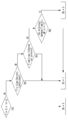
도 6은 본 발명의 일 실시예에 따른 인터 예측 방법의 흐름도이다.6 is a flowchart of an inter prediction method according to an embodiment of the present invention.
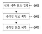
도 6을 참조하면, 인터 예측 방법은, 현재 블록의 인터 예측 모드를 결정하는 단계(S601), 결정된 인터 예측 모드에 따라 현재 블록의 움직임 정보를 획득하는 단계(S602) 및 획득된 움직임 정보에 기초하여, 현재 블록에 대한 움직임 보상 예측을 수행하는 단계(S603)를 포함한다.Referring to FIG. 6, the inter prediction method is based on determining an inter prediction mode of the current block (S601), obtaining motion information of a current block according to the determined inter prediction mode (S602), and obtained motion information In step S603, motion compensation prediction for the current block is performed.
여기서, 인터 예측 모드는 현재 블록의 움직임 정보를 결정하기 위한 다양한 기법들을 나타내는 것으로, 병진(Translation) 움직임 정보를 이용하는 인터 예측 모드와, 어파인(Affine) 움직임 정보를 이용하는 인터 예측 모드를 포함할 수 있다. 일 예로, 병진 움직임 정보를 이용하는 인터 예측 모드는, 머지 모드 및 모션 벡터 예측 모드를 포함하고, 어파인 움직임 정보를 이용하는 인터 예측 모드는 어파인 머지 모드 및 어파인 모션 벡터 예측 모드를 포함할 수 있다. 현재 블록의 움직임 정보는, 인터 예측 모드에 따라, 현재 블록에 이웃하는 이웃 블록 또는 비트스트림으로부터 파싱되는 정보를 기초로 결정될 수 있다.Here, the inter prediction mode represents various techniques for determining motion information of a current block, and may include an inter prediction mode using translation motion information and an inter prediction mode using affine motion information. have. For example, the inter prediction mode using translational motion information may include a merge mode and a motion vector prediction mode, and the inter prediction mode using affine motion information may include affine merge mode and affine motion vector prediction mode. . Motion information of the current block may be determined based on information parsed from a neighboring block or a bitstream neighboring the current block according to the inter prediction mode.
일 예로, 현재 블록의 움직임 정보는 현재 블록과 동일한 픽처에 포함된 공간적 이웃 블록 또는 현재 블록과 상이한 픽처에 포함된 콜로케이티드 블록의 움직임 정보를 기초로 유도될 수 있다. 공간적 이웃 블록은, 현재 블록의 상단에 인접하는 이웃 블록, 좌측에 인접하는 이웃 블록, 좌측 상단 코너에 인접하는 이웃 블록, 우측 상단 코너에 인접하는 이웃 블록 또는 좌측 하단 코너에 인접하는 이웃 블록 중 적어도 하나를 포함한다. 콜로케이티드 블록은 콜 픽처 내 현재 블록과 동일한 위치 및 크기를 가질 수 있다. 일 예로, 도 7은 콜로케이티드 블록을 나타낸 도면이다. 콜 픽처는 참조 픽처들 중 어느 하나를 가리키는 인덱스 정보에 의해 특정될 수 있다.For example, motion information of a current block may be derived based on motion information of a spatial neighboring block included in the same picture as the current block or a collocated block included in a picture different from the current block. The spatial neighboring block includes at least one of a neighboring block adjacent to the top of the current block, a neighboring block adjacent to the left, a neighboring block adjacent to the upper left corner, a neighboring block adjacent to the upper right corner, or a neighboring block adjacent to the lower left corner. Includes one. The collocated block may have the same position and size as the current block in the call picture. As an example, FIG. 7 is a view showing a collocated block. The call picture can be specified by index information indicating any one of the reference pictures.
현재 블록의 움직임 벡터의 정밀도는 복수의 움직임 벡터 정밀도 후보들 중에서 어느 하나로 결정될 수 있다. 일 예로, 움직임 벡터 정밀도 후보는 옥토펠, 쿼터펠, 하프펠, 정수펠, 2정수펠 또는 4-정수펠 중 적어도 하나를 포함할 수 있다. 움직임 벡터 정밀도 후보의 개수 또는 종류는 시퀀스, 슬라이스 또는 블록 단위로 결정될 수 있다. 일 예로, 움직임 벡터 정밀도 후보의 개수 또는 종류를 결정하기 위한 정보가 비트스트림을 통해 시그날링될 수 있다. 또는, 현재 블록의 인터 예측 모드 또는 어파인 모션 모델의 사용 여부에 기초하여 움직임 벡터 정밀도 후보의 개수 또는 종류가 결정될 수 있다. 복수의 움직임 벡터 정밀도 후보 중 어느 하나를 특정하기 위한 정보가 비트스트림을 통해 시그날링될 수도 있다. The precision of the motion vector of the current block may be determined by any one of a plurality of motion vector precision candidates. As an example, the motion vector precision candidate may include at least one of an octopel, a quarterpell, a half-pellet, an integer-pellet, a 2- integer-pellet, or a 4-integer-pellet. The number or type of motion vector precision candidates may be determined in units of sequences, slices, or blocks. For example, information for determining the number or type of motion vector precision candidates may be signaled through a bitstream. Alternatively, the number or type of motion vector precision candidates may be determined based on whether an inter prediction mode or an affine motion model of the current block is used. Information for specifying any one of a plurality of motion vector precision candidates may be signaled through a bitstream.
인트라 예측은 현재 블록 주변에 부호화/복호화가 완료된 복원 샘플을 이용하여, 현재 블록을 예측하는 것이다. 이때, 현재 블록의 인트라 예측에는, 인루프 필터가 적용되기 전의 복원 샘플이 이용될 수 있다.Intra prediction is to predict a current block by using a reconstructed sample that has been encoded / decoded around the current block. In this case, a reconstructed sample before the in-loop filter is applied may be used for intra prediction of the current block.
인트라 예측 기법은 매트릭스(Matrix)에 기반한 인트라 예측 및 주변 복원 샘플과의 방향성을 고려한 일반 인트라 예측을 포함한다. 현재 블록의 인트라 예측 기법을 지시하는 정보가 비트스트림을 통해 시그날링될 수 있다. 상기 정보는 1비트의 플래그일 수 있다. 또는, 현재 블록의 위치, 크기, 형태 또는 이웃 블록의 인트라 예측 기법 중 적어도 하나에 기초하여, 현재 블록의 인트라 예측 기법을 결정할 수 있다. 일 예로, 현재 블록이 픽처 바운더리를 걸쳐 존재하는 경우, 현재 블록에는 매트릭트에 기반한 인트라 예측이 적용되지 않도록 설정될 수 있다. The intra prediction technique includes matrix-based intra prediction and general intra prediction considering directionality with a surrounding reconstructed sample. Information indicating the intra prediction technique of the current block may be signaled through a bitstream. The information may be a flag of 1 bit. Alternatively, the intra prediction technique of the current block may be determined based on at least one of the location, size, shape of the current block, or intra prediction technique of the neighboring block. For example, when a current block exists across a picture boundary, it may be set so that intra-prediction based on a matrix is not applied to the current block.
매트릭스에 기반한 인트라 예측은, 부호화기 및 복호화기에서 기 저장된 매트릭스와, 현재 블록 주변의 복원 샘플 사이의 행렬 곱에 기반하여, 현재 블록의 예측 블록을 획득하는 방법이다. 기 저장된 복수개의 매트릭스들 중 어느 하나를 특정하기 위한 정보가 비트스트림을 통해 시그날링될 수 있다. 복호화기는 상기 정보 및 현재 블록의 크기에 기초하여, 현재 블록의 인트라 예측을 위한 매트릭스를 결정할 수 있다.Matrix-based intra prediction is a method of obtaining a prediction block of a current block based on a matrix product between a matrix previously stored in an encoder and a decoder and reconstructed samples around the current block. Information for specifying any one of a plurality of pre-stored matrices may be signaled through a bitstream. The decoder may determine a matrix for intra prediction of the current block based on the information and the size of the current block.
일반 인트라 예측은, 비방향성 인트라 예측 모드 또는 방향성 인트라 예측 모드에 기초하여, 현재 블록에 대한 예측 블록을 획득하는 방법이다. 이하, 도면을 참조하여, 일반 인트라 예측에 기초한 인트라 예측 수행 과정에 대해 보다 상세히 살펴보기로 한다.General intra prediction is a method of obtaining a prediction block for a current block based on a non-directional intra prediction mode or a directional intra prediction mode. Hereinafter, a process of performing intra prediction based on general intra prediction will be described in more detail with reference to the drawings.
도 8은 본 발명의 일 실시예에 따른, 인트라 예측 방법의 흐름도이다.8 is a flowchart of an intra prediction method according to an embodiment of the present invention.
현재 블록의 참조 샘플 라인을 결정할 수 있다(S801). 참조 샘플 라인은 현재 블록의 상단 및/또는 좌측으로부터 k번째 떨어진 라인에 포함된 참조 샘플들의 집합을 의미한다. 참조 샘플은 현재 블록 주변 부호화/복호화가 완료된 복원 샘플로부터 유도될 수 있다. The reference sample line of the current block may be determined (S801). The reference sample line means a set of reference samples included in a line k-th from the top and / or left of the current block. The reference sample may be derived from a reconstructed sample in which encoding / decoding of a current block is completed.
복수의 참조 샘플 라인들 중 현재 블록의 참조 샘플 라인을 식별하는 인덱스 정보가 비트스트림을 통해 시그날링될 수 있다. 일 예로, 현재 블록의 참조 샘플 라인을 특정하기 위한 인덱스 정보 intra_luma_ref_idx가 비트스트림을 통해 시그날링될 수 있다. 상기 인덱스 정보는 코딩 블록 단위로 시그날링될 수 있다. Index information identifying a reference sample line of a current block among a plurality of reference sample lines may be signaled through a bitstream. As an example, index information intra_luma_ref_idx for specifying a reference sample line of the current block may be signaled through a bitstream. The index information may be signaled in units of coding blocks.
복수의 참조 샘플 라인들은, 현재 블록에 상단 및/또는 좌측 1번째 라인, 2번째 라인, 3번째 라인 또는 4번째 라인 중 적어도 하나를 포함할 수 있다. 복수개의 참조 샘플 라인들 중 현재 블록의 상단에 인접하는 행 및 현재 블록의 좌측에 인접하는 열로 구성된 참조 샘플 라인을 인접 참조 샘플 라인이라 호칭하고, 그 이외의 참조 샘플 라인을 비인접 참조 샘플 라인이라 호칭할 수도 있다. The plurality of reference sample lines may include at least one of a top line and / or a left first line, a second line, a third line, or a fourth line in the current block. A reference sample line composed of a row adjacent to the top of the current block and a column adjacent to the left of the current block among the plurality of reference sample lines is referred to as an adjacent reference sample line, and other reference sample lines are referred to as non-contiguous reference sample lines. It can also be called.
도 9는 참조 샘플 라인들을 나타낸 도면이다.9 is a diagram showing reference sample lines.
도 9에서는 현재 블록에 인접하는 행/열로 구성된 하나의 인접 참조 샘플 라인과 현재 블록에 인접하지 않는 행/열로 구성된 세개의 비인접 참조 샘플 라인들을 도시하였다.FIG. 9 shows one adjacent reference sample line composed of rows / columns adjacent to the current block and three non-contiguous reference sample lines composed of rows / columns not adjacent to the current block.
복수의 참조 샘플 라인들 중 일부만이 현재 블록의 참조 샘플 라인으로 선택될 수 있다. 일 예로, 도 9에 도시된 참조 샘플 라인들 중 제2 비인접 참조 샘플 라인을 제외한 잔여 참조 샘플 라인들을 후보 참조 샘플 라인들로 설정할 수 있다. 표 1은 후보 참조 샘플 라인들 각각에 할당되는 인덱스를 나타낸 것이다. Only some of the plurality of reference sample lines may be selected as the reference sample line of the current block. For example, among the reference sample lines illustrated in FIG. 9, residual reference sample lines other than the second non-adjacent reference sample line may be set as candidate reference sample lines. Table 1 shows an index assigned to each of the candidate reference sample lines.
설명한 것 보다 더 많은 수의 후보 참조 샘플 라인들을 설정하거나, 더 적은 수의 후보 참조 샘플 라인들을 설정할 수도 있다. 또한, 후보 참조 샘플 라인으로 설정되는 비인접 참조 샘플 라인의 개수 또는 위치는 설명한 예에 한정되지 아니한다. 일 예로, 제1 비인접 참조 샘플 라인 및 제3 비인접 참조 샘플 라인을 후보 참조 샘플 라인들로 설정하거나, 제2 비인접 참조 샘플 라인 및 제3 비인접 참조 샘플 라인을 후보 참조 샘플 라인들로 설정할 수도 있다. 또는, 제1 비인접 참조 샘플 라인, 제2 비인접 참조 샘플 라임 및 제3 비인접 참조 샘플 라인을 모두 후보 참조 샘플 라인들로 설정할 수도 있다.후보 참조 샘플 라인들의 개수 또는 종류는 현재 블록의 크기, 형태, 위치, 서브 블록으로의 분할 여부 또는 인트라 예측 모드 중 적어도 하나에 기초하여 결정될 수 있다. More candidate reference sample lines may be set than described, or fewer candidate reference sample lines may be set. Also, the number or location of non-contiguous reference sample lines set as candidate reference sample lines is not limited to the described example. For example, the first non-contiguous reference sample line and the third non-contiguous reference sample line are set as candidate reference sample lines, or the second non-contiguous reference sample line and the third non-contiguous reference sample line are candidate reference sample lines. You can also set. Alternatively, the first non-contiguous reference sample line, the second non-contiguous reference sample lime, and the third non-contiguous reference sample line may be set as candidate reference sample lines. The number or type of candidate reference sample lines is the size of the current block , It may be determined based on at least one of a shape, a location, whether to divide into sub-blocks, or an intra prediction mode.
현재 블록의 위치, 크기, 형태 또는 이웃 블록의 예측 부호화 모드 중 적어도 하나에 기초하여, 현재 블록의 참조 샘플 라인을 결정할 수도 있다. 일 예로, 현재 블록이 픽처, 타일, 슬라이스 또는 코딩 트리 유닛의 경계에 접하는 경우, 인접 참조 샘플 라인을 현재 블록의 참조 샘플 라인으로 결정할 수 있다.A reference sample line of the current block may be determined based on at least one of a position, size, shape of the current block, or a prediction coding mode of a neighboring block. For example, when a current block touches a boundary of a picture, tile, slice, or coding tree unit, an adjacent reference sample line may be determined as a reference sample line of the current block.
또는, 현재 블록이 비정방형인 경우, 인접 참조 샘플 라인을 현재 블록의 참조 샘플 라인으로 결정할 수 있다. 또는, 현재 블록의 너비 및 높이비가 문턱값 이상 또는 문턱값 이하인 경우, 인접 참조 샘플 라인을 현재 블록의 참조 샘플 라인으로 결정할 수 있다. Alternatively, when the current block is non-square, an adjacent reference sample line may be determined as a reference sample line of the current block. Alternatively, when the width and height ratio of the current block is greater than or equal to a threshold or less than a threshold, the adjacent reference sample line may be determined as the reference sample line of the current block.
참조 샘플 라인은 현재 블록의 상단에 위치하는 상단 참조 샘플들 및 현재 블록의 좌측에 위치하는 좌측 참조 샘플들을 포함할 수 있다. 상단 참조 샘플들 및 좌측 참조 샘플들은 현재 블록 주변의 복원 샘플들로부터 유도될 수 있다. 상기 복원 샘플들은 인루프 필터가 적용되기 이전 상태일 수 있다.The reference sample line may include top reference samples located at the top of the current block and left reference samples located at the left of the current block. Upper reference samples and left reference samples may be derived from reconstructed samples around the current block. The reconstructed samples may be in a state before an in-loop filter is applied.
참조 샘플 라인에 포함된 참조 샘플들의 개수는 참조 샘플 라인과 참조 샘플 라인 사이의 거리에 기초하여 결정될 수 있다. 일 예로, 현재 블록과의 거리가 i인 참조 샘플 라인에 포함된 참조 샘플들의 개수가 현재 블록과의 거리가 i-1인 참조 샘플 라인에 포함된 참조 샘플들의 개수보다 더 큰 값을 가질 수 있다. 이에 따라, 비인접 참조 샘플 라인에 포함된 참조 샘플들의 개수는 인접 참조 샘플 라인에 포함된 참조 샘플들의 개수보다 큰 값을 가질 수 있다.The number of reference samples included in the reference sample line may be determined based on the distance between the reference sample line and the reference sample line. For example, the number of reference samples included in the reference sample line whose distance from the current block is i may have a value greater than the number of reference samples included in the reference sample line whose distance from the current block is i-1. . Accordingly, the number of reference samples included in the non-contiguous reference sample line may have a value greater than the number of reference samples included in the adjacent reference sample line.
현재 블록과의 거리가 i인 비인접 참조 샘플 라인에 포함된 참조 샘플들의 개수와 인접 참조 샘플 라인에 포함된 참조 샘플들의 개수 차분을 참조 샘플 개수 오프셋이라 정의할 수 있다. 이때, 현재 블록의 상단에 위치하는 상단 참조 샘플들의 개수 차분을 offsetX[i]라 정의하고, 현재 블록의 좌측에 위치하는 좌측 참조 샘플들의 개수 차분을 offsetY[i]라 정의할 수 있다. offsetX 및 offsetY는 현재 블록과 비인접 참조 샘플 라인의 거리에 기초하여 결정될 수 있다. 일 예로, offsetX 및 offsetY는 i의 정수배로 설정될 수 있다. 일 예로, offsetX[i] 및 offset[i]는 2i일 수 있다. The difference between the number of reference samples included in the non-contiguous reference sample line whose distance from the current block is i and the number of reference samples included in the adjacent reference sample line may be defined as an offset of the reference sample number. At this time, the difference between the number of upper reference samples located at the top of the current block may be defined as offsetX [i], and the difference between the number of left reference samples located at the left of the current block may be defined as offsetY [i]. offsetX and offsetY may be determined based on the distance between the current block and the non-contiguous reference sample line. For example, offsetX and offsetY may be set to an integer multiple of i. For example, offsetX [i] and offset [i] may be 2i.
또는, 현재 블록의 너비 및 높이비에 기초하여 참조 샘플 개수 오프셋을 결정할 수도 있다. 수학식 1은 현재 블록의 너비 및 높이비를 수치화하는 일 예를 나타낸 것이다. Alternatively, the reference sample number offset may be determined based on the width and height ratio of the current block.
![]()
![]()
수학식 1에 표현된 것과 다른 방법으로 현재 블록의 너비 및 높이비를 수치화하는 것 역시 가능하다.It is also possible to quantify the width and height ratio of the current block in a different way from that expressed in
현재 블록의 너비 및 높이비를 기초로 offsetX 및 offsetY의 값을 결정할 수 있다. 예를 들어, whRatio의 값이 1보다 큰 경우에는 offsetX의 값을 offsetY의 값보다 크게 설정할 수 있다. 일 예로, offsetX의 값은 1로 설정되고, offsetY의 값은 0으로 설정될 수 있다. 반면, whRatio의 값이 1보다 작은 경우에는 offsetX의 값보다 offsetY의 값을 더 크게 설정할 수 있다. 일 예로, offsetX의 값은 0으로 설정되고, offsetY의 값은 1로 설정될 수 있다. The values of offsetX and offsetY can be determined based on the width and height ratio of the current block. For example, when the value of whRatio is greater than 1, the value of offsetX can be set larger than the value of offsetY. For example, the value of offsetX may be set to 1, and the value of offsetY may be set to 0. On the other hand, when the value of whRatio is less than 1, the value of offsetY can be set larger than the value of offsetX. For example, the value of offsetX may be set to 0, and the value of offsetY may be set to 1.
x축 및 y축 좌표가 동일한 좌측 상단 참조 샘플 제외, 현재 블록과의 거리가 i인 비인접 참조 샘플 라인은 (refW + offsetX[i])개의 상단 참조 샘플들과 (refH + offsetY[i])개의 좌측 참조 샘플들로 구성될 수 있다. 여기서, refW 및 refH는 인접 참조 샘플 라인의 길이를 나타내는 것으로, 각각 다음의 수학식 2 및 3과 같이 설정될 수 있다.Excluding the upper left reference sample with the same x-axis and y-axis coordinates, the non-contiguous reference sample line with the distance from the current block is (refW + offsetX [i]) and (refH + offsetY [i]) It can be made up of left reference samples. Here, refW and refH indicate the lengths of adjacent reference sample lines, and may be set as shown in
![]()
![]()
![]()
![]()
수학식 2 및 수학식 3에서, nTbW는 인트라 예측이 수행되는 코딩 블록 또는 변환 블록의 너비를 나타내고, nTbH는 인트라 예측이 수행되는 코딩 블록 또는 변환 블록의 높이를 나타낸다. In
결과적으로, 현재 블록과의 거리가 i인 참조 샘플 라인은 (refW + refH + offsetX[i] + offsetY[i] + 1)개의 참조 샘플들로 구성될 수 있다. As a result, a reference sample line having a distance from the current block i may be composed of (refW + refH + offsetX [i] + offsetY [i] + 1) reference samples.
현재 블록의 인트라 예측 모드에 따라, 참조 샘플 라인에 속한 참조 샘플들 중 적어도 하나를 이용하여, 예측 샘플을 획득할 수 있다.According to the intra prediction mode of the current block, a prediction sample may be obtained using at least one of the reference samples belonging to the reference sample line.
다음으로, 현재 블록의 인트라 예측 모드를 결정할 수 있다(S802). 현재 블록의 인트라 예측 모드는 비방향성 인트라 예측 모드 또는 방향성 인트라 예측 모드 중 적어도 하나가 현재 블록의 인트라 예측 모드로 결정될 수 있다. 비방향성 인트라 예측 모드는, 플래너 및 DC를 포함하고, 방향성 인트라 예측 모드는 좌하단 대각 방향부터 우상단 대각 방향까지 33개 또는 65개의 모드들을 포함한다. Next, the intra prediction mode of the current block may be determined (S802). As for the intra prediction mode of the current block, at least one of the non-directional intra prediction mode or the directional intra prediction mode may be determined as the intra prediction mode of the current block. The non-directional intra prediction mode includes a planner and DC, and the directional intra prediction mode includes 33 or 65 modes from the lower left diagonal direction to the upper right diagonal direction.
도 10은 인트라 예측 모드들을 나타낸 도면이다. 10 is a diagram showing intra prediction modes.
도 10의 (a)는 35개의 인트라 예측 모드를 나타낸 것이고, 도 10의 (b)는 67개의 인트라 예측 모드들을 나타낸 것이다.FIG. 10 (a) shows 35 intra prediction modes, and FIG. 10 (b) shows 67 intra prediction modes.
도 10에 도시된 것보다 더 많은 수 혹은 더 적은 수의 인트라 예측 모드들이 정의될 수도 있다. More or fewer intra prediction modes than those shown in FIG. 10 may be defined.
현재 블록에 인접하는 이웃 블록의 인트라 예측 모드를 기초로, MPM(Most Probable Mode)을 설정할 수 있다. 여기서, 이웃 블록은, 현재 블록의 좌측에 인접하는 좌측 이웃 블록 및 현재 블록의 상단에 이웃하는 상단 이웃 블록을 포함할 수 있다. 현재 블록의 좌측 상단 샘플의 좌표를 (0, 0)이라 할 때, 좌측 이웃 블록은 (-1, 0), (-1, H-1) 또는 (-1, (H-1)/2) 위치의 샘플을 포함할 수 있다. 여기서, H는 현재 블록의 높이를 나타낸다. 상단 이웃 블록은 (0, -1), (W-1, -1) 또는 ((W-1)/2, -1) 위치의 샘플을 포함할 수 있다. 여기서, W는 현재 블록의 너비를 나타낸다.Based on the intra prediction mode of a neighboring block adjacent to the current block, a MPM (Most Probable Mode) may be set. Here, the neighboring block may include a left neighboring block adjacent to the left side of the current block and an upper neighboring block neighboring the top of the current block. When the coordinates of the upper left sample of the current block are (0, 0), the left neighboring block is (-1, 0), (-1, H-1) or (-1, (H-1) / 2) It may include a sample of the location. Here, H represents the height of the current block. The upper neighboring block may include samples at positions (0, -1), (W-1, -1) or ((W-1) / 2, -1). Here, W represents the width of the current block.
이웃 블록이 일반 인트라 예측으로 부호화된 경우, 이웃 블록의 인트라 예측 모드에 기초하여 MPM을 유도할 수 있다. 구체적으로, 좌측 이웃 블록의 인트라 예측 모드를 변수 candIntraPredModeA로 설정하고, 상단 이웃 블록의 인트라 예측 모드를 변수 candIntraPredModeB로 설정할 수 있다. When the neighboring block is encoded with the normal intra prediction, MPM may be derived based on the intra prediction mode of the neighboring block. Specifically, the intra prediction mode of the left neighboring block may be set to the variable candIntraPredModeA, and the intra prediction mode of the upper neighboring block may be set to the variable candIntraPredModeB.
이때, 이웃 블록이 이용 불가능한 경우(예컨대, 이웃 블록이 아직 부호화/복호화되지 않은 경우 또는 이웃 블록의 위치가 픽처 경계를 벗어난 경우), 이웃 블록이 매트릭스에 기반한 인트라 예측으로 부호화된 경우, 이웃 블록이 인터 예측으로 부호화된 경우 또는 이웃 블록이 현재 블록과 상이한 코딩 트리 유닛에 포함된 경우에 있어서, 이웃 블록의 인트라 예측 모드를 기초로 유도되는 변수 candIntraPredModeX (여기서, X는 A 또는 B)를 디폴트 모드로 설정할 수 있다. 여기서, 디폴트 모드는 플래너, DC, 수직 방향 모드 또는 수평 방향 모드 중 적어도 하나를 포함할 수 있다. In this case, when the neighboring block is unavailable (eg, when the neighboring block has not yet been encoded / decoded or when the position of the neighboring block is outside the picture boundary), when the neighboring block is encoded with matrix-based intra prediction, the neighboring block is The variable candIntraPredModeX (where X is A or B), which is derived based on the intra prediction mode of the neighboring block, is coded as the default mode when it is encoded with inter prediction or when a neighboring block is included in a coding tree unit different from the current block. Can be set. Here, the default mode may include at least one of a planner, DC, vertical direction mode, or horizontal direction mode.
또는, 이웃 블록이 매트릭스에 기반한 인트라 예측으로 부호화된 경우, 매트릭스들 중 어느 하나를 특정하기 위한 인덱스 값에 대응하는 인트라 예측 모드를 candIntraPredModeX로 설정할 수 있다. 이를 위해, 매트릭스를 특정하기 위한 인덱스 값들과 인트라 예측 모드들의 매핑 관계를 나타내는 룩업 테이블이 부호화기 및 복호화기에 기 저장될 수 있다. Alternatively, when a neighboring block is encoded with intra prediction based on a matrix, an intra prediction mode corresponding to an index value for specifying any one of the matrices may be set to candIntraPredModeX. To this end, a lookup table representing a mapping relationship between index values for specifying a matrix and intra prediction modes may be pre-stored in the encoder and decoder.
변수 candIntraPredModeA 및 변수 candIntraPredModeB에 기초하여, MPM들을 유도할 수 있다. 일 예로, candIntraPredModeA 및 candIntraPredModeB를 MPM으로 설정하거나, candIntraPredModeA 또는 candIntraPredModeB 중 큰 값 또는 작은 값과 유사한 인트라 예측 모드를 MPM으로 설정할 수 있다. 여기서, candIntraPredModeX (X는 A 또는 B)와 유사한 인트라 예측 모드는 candIntraPredModeX와 인덱스 차분값이 ±1 또는 ±2인 인트라 예측 모드일 수 있다.Based on the variables candIntraPredModeA and variable candIntraPredModeB, MPMs can be derived. For example, candIntraPredModeA and candIntraPredModeB may be set to MPM, or an intra prediction mode similar to a larger or smaller value among candIntraPredModeA or candIntraPredModeB may be set to MPM. Here, an intra prediction mode similar to candIntraPredModeX (X is A or B) may be an intra prediction mode having an index difference value of ± 1 or ± 2 from candIntraPredModeX.
MPM 리스트에 포함되는 MPM의 개수는 부호화기 및 복호화기에서 기 설정될 수 있다. 일 예로, MPM의 개수는, 3개, 4개, 5개 혹은 6개일 수 있다. 또는, MPM의 개수를 나타내는 정보가 비트스트림을 통해 시그날링될 수 있다. 또는, 이웃 블록의 예측 부호화 모드, 현재 블록의 크기, 형태 또는 참조 샘플 라인 인덱스 중 적어도 하나에 기초하여 MPM의 개수가 결정될 수 있다. 일 예로, 인접 참조 샘플 라인이 현재 블록의 참조 샘플 라인으로 결정된 경우에는 N개의 MPM들이 이용되는 반면, 비인접 참조 샘플 라인이 현재 블록의 참조 샘플 라인으로 결정된 경우에는 M개의 MPM들이 이용될 수 있다. M은 N보다 작은 자연수로, 일 예로, N은 6이고, M은 5, 4 또는 3일 수 있다. 이에 따라, 현재 블록의 참조 샘플 라인의 인덱스가 0이고, MPM 플래그가 참인 경우, 현재 블록의 인트라 예측 모드는 6개의 후보 인트라 예측 모드들 중 어느 하나로 결정되는 반면, 현재 블록의 참조 샘플 라인의 인덱스가 0보다 크고, MPM 플래그가 참인 경우, 현재 블록의 인트라 예측 모드는 5개의 후보 인트라 예측 모드들 중 어느 하나로 결정될 수 있다.The number of MPMs included in the MPM list may be preset in the encoder and decoder. For example, the number of MPMs may be 3, 4, 5, or 6. Alternatively, information indicating the number of MPMs may be signaled through a bitstream. Alternatively, the number of MPMs may be determined based on at least one of a prediction coding mode of a neighboring block, a size, a shape of a current block, or a reference sample line index. For example, when the adjacent reference sample line is determined as the reference sample line of the current block, N MPMs are used, whereas when the non-contiguous reference sample line is determined as the reference sample line of the current block, M MPMs may be used. . M is a natural number smaller than N, for example, N is 6 and M may be 5, 4 or 3. Accordingly, when the index of the reference sample line of the current block is 0 and the MPM flag is true, the intra prediction mode of the current block is determined to be one of six candidate intra prediction modes, while the index of the reference sample line of the current block When is greater than 0 and the MPM flag is true, the intra prediction mode of the current block may be determined by any one of 5 candidate intra prediction modes.
또는, 현재 블록의 참조 샘플 라인의 인덱스와 무관하게 고정된 개수(예컨대, 6개 또는 5개)의 MPM 후보를 사용할 수도 있다.Alternatively, a fixed number (eg, 6 or 5) of MPM candidates may be used regardless of the index of the reference sample line of the current block.
후술되는 실시예들에서는 MPM의 개수가 6개인 것으로 가정하고, 6개의 MPM들을 MPM[0], MPM[1], MPM[2], MPM[3], MPM[4] 및 MPM[5]라 호칭하기로 한다. MPM들의 개수가 6개보다 적은 실시예는, 후술되는 실시예들에서 설명하는 6개의 MPM들 중 일부만을 이용하여 구현될 수 있다. 또는, MPM들의 개수가 6개보다 많은 실시예는 후술되는 실시예들에서 설명하는 6개의 MPM들을 포함하여 구현될 수 있다.In the embodiments described below, it is assumed that the number of MPMs is 6, and the 6 MPMs are referred to as MPM [0], MPM [1], MPM [2], MPM [3], MPM [4] and MPM [5]. Let's call it title. An embodiment in which the number of MPMs is less than six may be implemented using only some of the six MPMs described in the embodiments described below. Alternatively, an embodiment in which the number of MPMs is more than six may be implemented including six MPMs described in the embodiments described below.
MPM들의 초기값은 candIntraPredModeA와 candIntraPredModeA와 상이한 비방향성 인트라 예측 모드 또는 방향성 인트라 예측 모드로 설정될 수 있다. 여기서, MPM으로 설정될 수 있는 방향성 인트라 예측 모드는 수직 방향의 인트라 예측 모드, 수평 방향의 인트라 예측 모드, 좌하단 대각 방향의 인트라 예측 모드, 좌상단 대각 방향의 인트라 예측 모드 또는 우상단 대각 방향의 인트라 예측 모드 중 적어도 하나를 포함할 수 있다. 일 예로, MPM들의 초기값은 다음과 같이 설정될 수 있다.The initial values of MPMs may be set to a non-directional intra prediction mode or a directional intra prediction mode different from candIntraPredModeA and candIntraPredModeA. Here, the directional intra prediction mode that can be set to MPM includes an intra prediction mode in the vertical direction, an intra prediction mode in the horizontal direction, an intra prediction mode in the lower left diagonal direction, an intra prediction mode in the upper left diagonal direction, or an intra prediction in the upper right diagonal direction. It may include at least one of the modes. For example, the initial values of MPMs may be set as follows.
MPM[0] = candIntraPredModeAMPM [0] = candIntraPredModeA
MPM[1] = (candIntraPredModeA == INTRA_PLANAR) ? INTRA_DC : INTRA_PLANARMPM [1] = (candIntraPredModeA == INTRA_PLANAR)? INTRA_DC: INTRA_PLANAR
MPM[2] = INTRA_ANGULAR50MPM [2] = INTRA_ANGULAR50
MPM[3] = INTRA_ANGULAR18MPM [3] = INTRA_ANGULAR18
MPM[4] = INTRA_ANGULAR2MPM [4] = INTRA_ANGULAR2
MPM[5] = INTRA_ANGULAR34MPM [5] = INTRA_ANGULAR34
상술한 예에서 ((A) ? B : C)는 A에 개시된 조건이 참인 경우, B값을 리턴하고, A에 개시된 조건이 거짓인 경우 C값을 리턴하는 함수를 나타낸다.In the above example, ((A)-B: C) represents a function that returns a value of B when the condition disclosed in A is true, and a value of C when the condition disclosed in A is false.
candIntraPredModeA 및 candIntraPredModeB가 동일하고, candIntraPredModeA가 방향성 인트라 예측 모드인 경우, MPM[0]를 candIntraPredModeA로 설정하고, candIntraPredModeA와 유사한 인트라 예측 모드들을 MPM들로 설정할 수 있다. candIntraPredModeA와 유사한 인트라 예측 모드는 candIntraPredModeA와 인덱스 차분값이 ±1 또는 ±2인 인트라 예측 모드일 수 있다. candIntraPredModeA와 유사한 인트라 예측 모드를 유도하기 위해 모듈로 연산(%) 및 오프셋이 이용될 수 있다. 또한, 비방향성 인트라 예측 모드 또는 candIntraPredModeA와의 각도 차분이 기 정의된 값인 인트라 예측 모드 중 적어도 하나를 MPM으로 설정할 수 있다. 여기서, candIntraPredModeA와의 각도 차분이 기 정의된 값인 인트라 예측 모드는 candIntraPredModeA와 수직인 인트라 예측 모드 또는 candIntraPredModeA와 반대 방향인 인트라 예측 모드일 수 있다. 일 예로, MPM들은 다음과 같이 유도될 수 있다.If candIntraPredModeA and candIntraPredModeB are the same and candIntraPredModeA is a directional intra prediction mode, MPM [0] can be set to candIntraPredModeA, and intra prediction modes similar to candIntraPredModeA can be set to MPMs. An intra prediction mode similar to candIntraPredModeA may be an intra prediction mode in which an index difference value between candIntraPredModeA is ± 1 or ± 2. Modulo operation (%) and offset can be used to derive an intra prediction mode similar to candIntraPredModeA. Also, at least one of a non-directional intra prediction mode or an intra prediction mode in which an angle difference from candIntraPredModeA is a predefined value may be set as the MPM. Here, the intra prediction mode in which the angle difference from candIntraPredModeA is a predefined value may be an intra prediction mode perpendicular to candIntraPredModeA or an intra prediction mode opposite to candIntraPredModeA. For example, MPMs may be derived as follows.
MPM[0] = candIntraPredModeAMPM [0] = candIntraPredModeA
MPM[1] = INTRA_PLANARMPM [1] = INTRA_PLANAR
MPM[2] = INTRA_DCMPM [2] = INTRA_DC
MPM[3] = 2 + ((candIntraPredModeA + 62) % 65)MPM [3] = 2 + ((candIntraPredModeA + 62)% 65)
MPM[4] = 2 + ((candIntraPredModeA - 1) % 65)MPM [4] = 2 + ((candIntraPredModeA-1)% 65)
MPM[5] = 2 + ((candIntraPredModeA + 94) % 65)MPM [5] = 2 + ((candIntraPredModeA + 94)% 65)
MPM[3]은 (candIntraPredModeA - 1)에 대응하고, MPM[4]는 (candIntraPredModeA + 1)에 대응한다. MPM[5]는 candIntraPredModeA와 수직인 인트라 예측 모드를 나타낸다.MPM [3] corresponds to (candIntraPredModeA-1), and MPM [4] corresponds to (candIntraPredModeA + 1). MPM [5] represents an intra prediction mode perpendicular to candIntraPredModeA.
candIntraPredModeA와 candIntraPredModeB가 상이한 경우, candIntraPredModeA 및 candIntraPredModeB를 각각 MPM[0] 및 MPM[1]로 설정할 수 있다. 또는, candIntraPredA와 candIntraPredModeB를 비교하여, 최대값을 MPM[0]로 설정하고, 최소값을 MPM[1]로 설정할 수 있다. 이와 반대로, 최소값을 MPM[0]로 설정하고, 최대값을 MPM[1]로 설정하는 것도 가능하다.When candIntraPredModeA and candIntraPredModeB are different, candIntraPredModeA and candIntraPredModeB can be set to MPM [0] and MPM [1], respectively. Or, by comparing candIntraPredA and candIntraPredModeB, the maximum value can be set to MPM [0] and the minimum value to MPM [1]. Conversely, it is also possible to set the minimum value to MPM [0] and the maximum value to MPM [1].
이때, candIntraPredModeA와 candIntraPredModeB가 모두 방향성 인트라 예측 모드인 경우, 비방향성 인트라 예측 모드를 MPM으로 설정할 수 있다. 일 예로, 플래너 및 DC가 각각 MPM[2] 및 MPM[3]으로 설정될 수 있다. In this case, when both candIntraPredModeA and candIntraPredModeB are directional intra prediction modes, the non-directional intra prediction mode may be set to MPM. As an example, the planner and DC may be set to MPM [2] and MPM [3], respectively.
추가로, candIntraPredModeA와 candIntraPredModeB 중 값이 큰 것 또는 작은 것과 유사한 인트라 예측 모드를 MPM으로 설정할 수 있다. candIntraPredModeX와 유사한 인트라 예측 모드는 candIntraPredModeX에 오프셋을 가산 또는 감산하여 유도될 수 있다. 이때, 오프셋의 최대 크기는 candIntraPredModeA 및 candIntraPredModeB 중 최대값과 최소값의 차분을 기초로 결정될 수 있다. 일 예로, 오프셋은, 1 또는 2와 같은 자연수 일 수 있다. Additionally, an intra prediction mode similar to a larger or smaller value among candIntraPredModeA and candIntraPredModeB can be set to MPM. An intra prediction mode similar to candIntraPredModeX can be derived by adding or subtracting an offset to candIntraPredModeX. At this time, the maximum size of the offset may be determined based on the difference between the maximum and minimum values of candIntraPredModeA and candIntraPredModeB. For example, the offset may be a natural number such as 1 or 2.
일 예로, MAX(candIntraPredModeA, candIntraPredModeB)에서 MIN(candIntraPredModeA, candIntraPredModeB)을 차분한 값이 64 또는 1이 아닌 경우, MPM[4] 및 MPM[5]는 다음과 같이 유도될 수 있다.For example, if the value obtained by subtracting MIN (candIntraPredModeA, candIntraPredModeB) from MAX (candIntraPredModeA, candIntraPredModeB) is not 64 or 1, MPM [4] and MPM [5] may be derived as follows.
MPM[4] = 2 + ((MAX(MPM[0], MPM[1]) + 62) % 65MPM [4] = 2 + ((MAX (MPM [0], MPM [1]) + 62)% 65
MPM[5] = 2 + ((MAX(MPM[0], MPM[1]) - 1) % 65MPM [5] = 2 + ((MAX (MPM [0], MPM [1])-1)% 65
여기서, MAX(A, B) 함수는 A와 B 중 큰 값을 리턴하는 함수이고, MIN(A, B) 함수는 A와 B 중 작은 값을 리턴하는 함수이다. MPM[4]는 (MAX(MPM[0], MPM[1]) - 1)에 대응하고, MPM[5]는 (MAX(MPM[0], MPM[1]) + 1)에 대응한다. 반면, MAX(candIntraPredModeA, candIntraPredModeB)에서 MIN(candIntraPredModeA, candIntraPredModeB)을 차분한 값이 64 또는 1인 경우, MPM[4] 및 MPM[5]는 다음과 같이 유도될 수 있다.Here, the MAX (A, B) function is a function that returns the larger value of A and B, and the MIN (A, B) function is a function that returns the smaller value of A and B. MPM [4] corresponds to (MAX (MPM [0], MPM [1])-1), and MPM [5] corresponds to (MAX (MPM [0], MPM [1]) + 1). On the other hand, when the value obtained by subtracting MIN (candIntraPredModeA, candIntraPredModeB) from MAX (candIntraPredModeA, candIntraPredModeB) is 64 or 1, MPM [4] and MPM [5] can be derived as follows.
MPM[4] = 2 + ((MAX(MPM[0], MPM[1]) + 61) % 65MPM [4] = 2 + ((MAX (MPM [0], MPM [1]) + 61)% 65
MPM[5] = 2 + (MAX(MPM[0], MPM[1]) % 65MPM [5] = 2 + (MAX (MPM [0], MPM [1])% 65
MPM[4]는 (MAX(MPM[0], MPM[1]) - 2)에 대응하고, MPM[5]는 (MAX(MPM[0], MPM[1]) + 2)에 대응한다.MPM [4] corresponds to (MAX (MPM [0], MPM [1])-2), and MPM [5] corresponds to (MAX (MPM [0], MPM [1]) + 2).
candIntraPredModeA와 candIntraPredModeB 중 어느 하나는 방향성 인트라 예측 모드인 반면, 다른 하나는 비방향성 인트라 예측 모드인 경우, MIN(candIntraPredModeA, candIntrapredModeB)와 동일하지 않은 비방향성 인트라 예측 모드, MAX(candIntraPredModeA, candIntraPredModeB)와 유사한 방향성 인트라 예측 모드, 또는 MAX(candIntraPredModeA, candIntraPredModeB)와 각도 차분이 기 정의된 값인 인트라 예측 모드 중 적어도 하나를 MPM으로 설정할 수 있다. 일 예로, MPM[2] 내지 MPM[5]는 다음과 같이 유도될 수 있다.One of candIntraPredModeA and candIntraPredModeB is a directional intra prediction mode, while the other is a non-directional intra prediction mode, a non-directional intra prediction mode not equal to MIN (candIntraPredModeA, candIntrapredModeB), similar to MAX (candIntraPredModeA, candIntraPredModeB) Intra prediction mode, or at least one of MAX (candIntraPredModeA, candIntraPredModeB) and an intra prediction mode in which an angle difference is a predefined value, may be set to MPM. For example, MPM [2] to MPM [5] can be derived as follows.
MPM[2] = ! MIN(MPM[0], MPM[1])MPM [2] =! MIN (MPM [0], MPM [1])
MPM[3] = 2 + ((MAX(MPM[0], MPM[1]) + 62) % 65MPM [3] = 2 + ((MAX (MPM [0], MPM [1]) + 62)% 65
MPM[4] = 2 + ((MAX(MPM[0], MPM[1]) - 1) % 65MPM [4] = 2 + ((MAX (MPM [0], MPM [1])-1)% 65
MPM[5] = 2 + ((MAX(MPM[0], MPM[1]) + 94) % 65MPM [5] = 2 + ((MAX (MPM [0], MPM [1]) + 94)% 65
MPM[2]는 MPM[0] 또는 MPM[1]과 동일하지 않은 비방향성 인트라 예측 모드를 나타낸다. 예컨대, MIN(MPM[0], MPM[1])이 DC인 경우, MPM[2]는 플래너로 설정되고, MIN(MPM[0], MPM[1])이 플래너인 경우, MPM[2]는 DC로 설정된다. MPM[3]은 ((MAX(MPM[0], MPM[1]) - 1)에 대응하고, MPM[4]는 (MAX(MPM[0], MPM[1]) + 1)에 대응한다. MPM[5]는 (MAX(MPM[0], MPM[1])와 수직인 인트라 예측 모드를 나타낸다. 위 열거된 예와 달리, (MAX(MPM[0], MPM[1])에 2를 가산 또는 감산하여 유도된 MPM을 MPM 리스트에 추가할 수도 있다.MPM [2] represents a non-directional intra prediction mode that is not the same as MPM [0] or MPM [1]. For example, when MIN (MPM [0], MPM [1]) is DC, MPM [2] is set as a planner, and when MIN (MPM [0], MPM [1]) is a planner, MPM [2] Is set to DC. MPM [3] corresponds to ((MAX (MPM [0], MPM [1])-1), and MPM [4] corresponds to (MAX (MPM [0], MPM [1]) + 1) MPM [5] represents the intra prediction mode perpendicular to (MAX (MPM [0], MPM [1]). Unlike the examples listed above, (MAX (MPM [0], MPM [1]) has 2 MPM derived by adding or subtracting may be added to the MPM list.
candIntraPredA와 candIntraPredB 중 어느 하나는 비방향성 인트라 모드이고, 다른 하나는 방향성 인트라 예측 모드인 경우, 즉, candIntraPredA와 PredIntraPredB 중 어느 하나는 2보다 작고 다른 하나는 2와 같거나 큰 경우, candIntraPredA 및 candIntraPredB 중 최대값을 MPM으로 설정할 수 있다. 또한, 상기 최대값과 유사한 인트라 예측 모드 또는 상기 최대값에 수직인 인트라 예측 모드를 MPM으로 설정할 수 있다. 일 예로, MPM[0] 내지 MPM[5]는 다음과 같이 유도될 수 있다.One of candIntraPredA and candIntraPredB is a non-directional intra-mode, and the other is a directional intra-prediction mode, that is, if either of candIntraPredA and PredIntraPredB is less than 2 and the other is equal to or greater than 2, the maximum of candIntraPredA and candIntraPredB The value can be set to MPM. Also, an intra prediction mode similar to the maximum value or an intra prediction mode perpendicular to the maximum value may be set to MPM. For example, MPM [0] to MPM [5] can be derived as follows.
MPM[0] = MAX(candIntraPredA, candIntraPredB)MPM [0] = MAX (candIntraPredA, candIntraPredB)
MPM[1] = INTRA_PLANARMPM [1] = INTRA_PLANAR
MPM[2] = INTRA_DCMPM [2] = INTRA_DC
MPM[3] = 2 + ((MAX(candIntraPredA, candIntraPredB) + 62) % 65MPM [3] = 2 + ((MAX (candIntraPredA, candIntraPredB) + 62)% 65
MPM[4] = 2 + ((MAX(candIntraPredA, candIntraPredB]) - 1) % 65MPM [4] = 2 + ((MAX (candIntraPredA, candIntraPredB])-1)% 65
MPM[5] = 2 + ((MAX(candIntraPredA, candIntraPredB) + 94) % 65MPM [5] = 2 + ((MAX (candIntraPredA, candIntraPredB) + 94)% 65
MPM[3]은 ((MAX(candIntraPredA, candIntraPredB) - 1)에 대응하고, MPM[4]는 (MAX(candIntraPredA, candIntraPredB) + 1)에 대응한다. MPM[5]는 (MAX(candIntraPredA, candIntraPredB)와 수직인 인트라 예측 모드를 나타낸다. 위 열거된 예와 달리, (MAX(candIntraPredA, candIntraPredB)에 2를 가산 또는 감산하여 유도된 MPM을 MPM 리스트에 추가할 수도 있다.MPM [3] corresponds to ((MAX (candIntraPredA, candIntraPredB)-1), and MPM [4] corresponds to (MAX (candIntraPredA, candIntraPredB) + 1) .MPM [5] corresponds to (MAX (candIntraPredA, candIntraPredB) Indicates an intra prediction mode perpendicular to) Unlike the examples listed above, MPM derived by adding or subtracting 2 to (MAX (candIntraPredA, candIntraPredB)) may be added to the MPM list.
현재 블록의 참조 샘플 라인의 인덱스를 고려하여, MPM들을 유도할 수 있다. 특히, 비인접 참조 샘플 라인이 현재 블록의 참조 샘플 라인으로 결정된 경우, 플래너 또는 DC와 같은 비방향성 예측 모드를 MPM으로 설정하지 않을 수 있다. 일 예로, MPM들의 초기값은 인접 참조 샘플 라인이 현재 블록의 참조 샘플 라인으로 결정되었는지 여부에 따라 다음과 같이 설정될 수 있다.MPMs may be derived by considering the index of the reference sample line of the current block. In particular, when the non-contiguous reference sample line is determined as the reference sample line of the current block, a non-directional prediction mode such as a planner or DC may not be set as MPM. For example, the initial values of MPMs may be set as follows according to whether the adjacent reference sample line is determined as the reference sample line of the current block.
MPM[0] = (IntraLumaRefLineIdx == 0) ? candIntraPredModeA : INTRA_ANGULAR2MPM [0] = (IntraLumaRefLineIdx == 0)? candIntraPredModeA: INTRA_ANGULAR2
MPM[1] = (IntraLumaRefLineIdx == 0) ? (candIntraPredModeA : == INTRA_PLANAR ? INTRA_DC : INTRA_PLANAR) : INTRA_ANGULAR18MPM [1] = (IntraLumaRefLineIdx == 0)? (candIntraPredModeA: == INTRA_PLANAR? INTRA_DC: INTRA_PLANAR): INTRA_ANGULAR18
MPM[2] = INTRA_ANGULAR50MPM [2] = INTRA_ANGULAR50
MPM[3] = (IntraLumaRefLineIdx == 0) ? INTRA_ANGULAR18 : INTRA_ANGULAR34 MPM [3] = (IntraLumaRefLineIdx == 0)? INTRA_ANGULAR18: INTRA_ANGULAR34
MPM[4] = (IntraLumaRefLineIdx == 0) ? INTRA_ANGULAR2 : INTRA_ANGULAR66 MPM [4] = (IntraLumaRefLineIdx == 0)? INTRA_ANGULAR2: INTRA_ANGULAR66
MPM[5] = (IntraLumaRefLineIdx == 0) ? INTRA_ANGULAR34 : INTRA_ANGULAR42 MPM [5] = (IntraLumaRefLineIdx == 0)? INTRA_ANGULAR34: INTRA_ANGULAR42
현재 블록의 참조 샘플 라인이 비인접 참조 샘플 라인이고, candIntraPredModeA 및 candIntraPredModeB가 모두 방향성 인트라 예측 모드인 경우, 다음과 같이 MPM들을 유도할 수 있다.If the reference sample line of the current block is a non-contiguous reference sample line, and both candIntraPredModeA and candIntraPredModeB are directional intra prediction modes, MPMs may be derived as follows.
MPM[0] = candIntraPredModeAMPM [0] = candIntraPredModeA
MPM[1] = candIntraPredModeBMPM [1] = candIntraPredModeB
MPM[2] = INTRA_ANGULAR2MPM [2] = INTRA_ANGULAR2
MPM[3] = INTRA_ANGULAR18MPM [3] = INTRA_ANGULAR18
MPM[4] = INTRA_ANGULAR50MPM [4] = INTRA_ANGULAR50
MPM[5] = INTRA_ANGULAR34MPM [5] = INTRA_ANGULAR34
현재 블록의 참조 샘플 라인이 비인접 참조 샘플 라인이고, candIntraPredModeA 및 candIntraPredModeB 중 어느 하나는 비방향성 인트라 예측 모드이고, 다른 하나는 방향성 인트라 예측 모드인 경우, 다음과 같이 MPM들을 유도할 수 있다.If the reference sample line of the current block is a non-contiguous reference sample line, and one of candIntraPredModeA and candIntraPredModeB is a non-directional intra prediction mode, and the other is a directional intra prediction mode, MPMs may be derived as follows.
MPM[0] = MAX(candIntraPredModeA, candIntraPredModeB)MPM [0] = MAX (candIntraPredModeA, candIntraPredModeB)
MPM[1] = INTRA_ANGULAR2MPM [1] = INTRA_ANGULAR2
MPM[2] = INTRA_ANGULAR18MPM [2] = INTRA_ANGULAR18
MPM[3] = INTRA_ANGULAR50MPM [3] = INTRA_ANGULAR50
MPM[4] = INTRA_ANGULAR34MPM [4] = INTRA_ANGULAR34
MPM[5] = INTRA_ANGULAR66MPM [5] = INTRA_ANGULAR66
복수의 MPM을 포함하는 MPM 리스트를 생성하고, 현재 블록의 인트라 예측 모드와 동일한 MPM이 MPM 리스트에 포함되어 있는지 여부를 나타내는 정보를 비트스트림을 통해 시그날링할 수 있다. 상기 정보는 1비트의 플래그로 MPM 플래그라 호칭될 수 있다. 상기 MPM 플래그가 현재 블록과 동일한 MPM이 MPM 리스트에 포함되어 있음을 나타내는 경우, MPM들 중 하나를 식별하는 인덱스 정보가 비트스트림을 통해 시그날링될 수 있다. 일 예로, 복수의 MPM들 중 어느 하나를 특정하는 인덱스 정보 mpm_idx가 비트스트림을 통해 시그날링될 수 있다. 상기 인덱스 정보에 의해 특정된 MPM이 현재 블록의 인트라 예측 모드로 설정될 수 있다. 상기 MPM 플래그가 현재 블록과 동일한 MPM이 MPM 리스트에 포함되어 있지 않음을 나타내는 경우, MPM들을 제외한 잔여 인트라 예측 모드들 중 어느 하나를 지시하는 잔여 모드 정보가 비트스트림을 통해 시그날링될 수 있다. 잔여 모드 정보는 MPM들을 제외한 잔여 인트라 예측 모드들에 인덱스를 재할당하였을 때, 현재 블록의 인트라 예측 모드에 대응되는 인덱스 값을 가리킨다. 복호화기에서는 MPM들을 오름차순으로 정렬하고, 잔여 모드 정보를 MPM들과 비교하여 현재 블록의 인트라 예측 모드를 결정할 수 있다. 일 예로, 잔여 모드 정보가 MPM과 같거나 작은 경우, 잔여 모드 정보에 1을 가산하여 현재 블록의 인트라 예측 모드를 유도할 수 있다. An MPM list including a plurality of MPMs may be generated, and information indicating whether the same MPM as the intra prediction mode of the current block is included in the MPM list may be signaled through a bitstream. The information may be called an MPM flag with a flag of 1 bit. When the MPM flag indicates that the same MPM as the current block is included in the MPM list, index information identifying one of the MPMs may be signaled through the bitstream. For example, index information mpm_idx specifying any one of a plurality of MPMs may be signaled through a bitstream. The MPM specified by the index information may be set as an intra prediction mode of the current block. When the MPM flag indicates that the same MPM as the current block is not included in the MPM list, residual mode information indicating any one of the remaining intra prediction modes excluding MPMs may be signaled through the bitstream. The residual mode information indicates an index value corresponding to the intra prediction mode of the current block when the index is reassigned to the remaining intra prediction modes excluding MPMs. The decoder can sort the MPMs in ascending order and compare the residual mode information with the MPMs to determine the intra prediction mode of the current block. For example, when the residual mode information is equal to or less than the MPM, the intra prediction mode of the current block may be derived by adding 1 to the residual mode information.
현재 블록의 인트라 예측 모드 유도 시, MPM들 중 일부와 잔여 모드 정보에 대한 비교는 생략될 수 있다. 일 예로, MPM들 중 비방향성 인트라 예측 모드인 MPM 들은 비교 대상에서 제외될 수 있다. 비방향성 인트라 예측 모드들이 MPM들로 설정된 경우, 잔여 모드 정보는 방향성 인트라 예측 모드를 가리킴이 명확하므로, 비방향성 인트라 예측 모드들을 제외한 잔여 MPM들과 잔여 모드 정보와의 비교를 통해 현재 블록의 인트라 예측 모드를 유도할 수 있다. 비방향성 인트라 예측 모드들을 비교 대상으로 제외하는 대신, 잔여 모드 정보에 비방향성 인트라 예측 모드들의 개수를 가산한 뒤, 그 결과값을 잔여 MPM들과 비교할 수 있다. When inducing the intra prediction mode of the current block, comparison of some of the MPMs and residual mode information may be omitted. For example, among the MPMs, the non-directional intra prediction modes MPMs may be excluded from comparison. When the non-directional intra prediction modes are set to MPMs, since it is clear that the residual mode information indicates a directional intra prediction mode, intra prediction of the current block through comparison of residual MPMs and residual mode information except for non-directional intra prediction modes The mode can be derived. Instead of excluding non-directional intra prediction modes as a comparison object, the number of non-directional intra prediction modes may be added to the residual mode information, and the result value may be compared with the remaining MPMs.
디폴트 모드를 MPM으로 설정하는 대신, 현재 블록의 인트라 예측 모드가 디폴트 모드인지 여부를 나타내는 정보를 비트스트림을 통해 시그날링할 수 있다. 상기 정보는 1비트의 플래그이고, 상기 플래그를 디폴트 모드 플래그라 호칭할 수 있다. 상기 디폴트 모드 플래그는 MPM 플래그가 현재 블록과 동일한 MPM이 MPM 리스트에 포함되어 있음을 나타내는 경우에 한하여 시그날링될 수 있다. 상술한 바와 같이, 디폴트 모드는, 플래너, DC, 수직 방향 모드 또는 수평 방향 모드 중 적어도 하나를 포함할 수 있다. 일 예로, 플래너가 디폴트 모드로 설정된 경우, 디폴트 모드 플래그는 현재 블록의 인트라 예측 모드가 플래너인지 여부를 지시할 수 있다. 디폴트 모드 플래그가 현재 블록의 인트라 예측 모드가 디폴트 모드가 아님을 가리키는 경우, 인덱스 정보에 의해 지시되는 MPM들 중 하나를 현재 블록의 인트라 예측 모드로 설정할 수 있다. Instead of setting the default mode to MPM, information indicating whether the intra prediction mode of the current block is the default mode may be signaled through a bitstream. The information is a 1-bit flag, and the flag may be referred to as a default mode flag. The default mode flag may be signaled only when the MPM flag indicates that the same MPM as the current block is included in the MPM list. As described above, the default mode may include at least one of a planner, DC, vertical direction mode, or horizontal direction mode. For example, when the planner is set as the default mode, the default mode flag may indicate whether the intra prediction mode of the current block is the planner. When the default mode flag indicates that the intra prediction mode of the current block is not the default mode, one of the MPMs indicated by the index information may be set as the intra prediction mode of the current block.
디폴트 모드 플래그가 이용되는 경우, 디폴트 모드와 동일한 인트라 예측 모드는 MPM으로 설정되지 않도록 설정될 수 있다. 일 예로, 디폴트 모드 플래그가 현재 블록의 인트라 예측 모드가 플래너인지 여부를 지시하는 경우, 상술한 6개의 MPM들 중 플래너에 해당하는 MPM을 다른 모드로 치환하거나, 플래너에 해당하는 MPM을 제외한 5개의 MPM들을 이용하여, 현재 블록의 인트라 예측 모드를 유도할 수 있다.When the default mode flag is used, the same intra prediction mode as the default mode may be set so as not to be set to MPM. For example, when the default mode flag indicates whether the intra prediction mode of the current block is a planner, among the six MPMs described above, the MPM corresponding to the planner is replaced with another mode, or five except the MPM corresponding to the planner. Using MPMs, the intra prediction mode of the current block can be derived.
복수개의 인트라 예측 모드들이 디폴트 모드들로 설정된 경우, 디폴트 모드들 중 어느 하나를 지시하는 인덱스 정보가 더 시그날링될 수 있다. 현재 블록의 인트라 예측 모드는 상기 인덱스 정보가 가리키는 디폴트 모드로 설정될 수 있다.When a plurality of intra prediction modes are set as default modes, index information indicating one of the default modes may be further signaled. The intra prediction mode of the current block may be set as a default mode indicated by the index information.
현재 블록의 참조 샘플 라인의 인덱스가 0이 아닌 경우에는 디폴트 모드를 이용하지 못하도록 설정할 수 있다. 일 예로, 비인접 참조 샘플 라인이 현재 블록의 참조 샘플 라인으로 결정된 경우, DC 모드 또는 플래너 모드와 같은 비방향성 인트라 예측 모드를 사용하지 않도록 설정할 수 있다. 이에 따라, 참조 샘플 라인의 인덱스가 0이 아닌 경우에는 디폴트 모드 플래그를 시그날링하지 않고, 상기 디폴트 모드 플래그의 값을 기 정의된 값(즉, 거짓)으로 설정할 수 있다.If the index of the reference sample line of the current block is not 0, it can be set to not use the default mode. For example, when the non-contiguous reference sample line is determined as the reference sample line of the current block, a non-directional intra prediction mode such as DC mode or planner mode may be set not to be used. Accordingly, when the index of the reference sample line is not 0, the default mode flag is not signaled and the default mode flag value can be set to a predefined value (ie, false).
현재 블록의 인트라 예측 모드가 결정되면, 결정된 인트라 예측 모드를 기초로, 현재 블록에 대한 예측 샘플들을 획득할 수 있다(S803).When the intra prediction mode of the current block is determined, prediction samples for the current block may be obtained based on the determined intra prediction mode (S803).
DC 모드가 선택된 경우, 참조 샘플들의 평균값을 기초로, 현재 블록에 대한 예측 샘플들이 생성된다. 구체적으로, 예측 블록 내 전체 샘플들의 값은 참조 샘플들의 평균값을 기초로 생성될 수 있다. 평균값은, 현재 블록의 상단에 위치하는 상단 참조 샘플들 및 현재 블록의 좌측에 위치하는 좌측 참조 샘플들 중 적어도 하나를 이용하여 유도될 수 있다. When the DC mode is selected, prediction samples for the current block are generated based on the average value of reference samples. Specifically, the values of all samples in the prediction block may be generated based on the average value of the reference samples. The average value may be derived using at least one of the top reference samples located at the top of the current block and the left reference samples located at the left of the current block.
현재 블록의 형태에 따라, 평균값을 유도하는데 이용되는 참조 샘플들의 개수 또는 범위가 달라질 수 있다. 일 예로, 현재 블록이 너비가 높이보다 큰 비정방형 블록인 경우, 상단 참조 샘플들만을 이용하여 평균값을 계산할 수 있다. 반면, 현재 블록이 너비가 높이보다 작은 비정방형 블록인 경우, 좌측 참조 샘플들만을 이용하여 평균값을 계산할 수 있다. 즉, 현재 블록의 너비 및 높이가 상이한 경우, 길이가 더 긴 쪽에 인접하는 참조 샘플들만을 이용하여 평균값을 계산할 수 있다. 또는, 현재 블록의 너비와 높이 비율에 기초하여, 상단 참조 샘플들만을 이용하여 평균값을 계산할 것인지 여부 또는 좌측 참조 샘플들만을 이용하여 평균값을 계산할 것인지 여부를 결정할 수 있다.Depending on the shape of the current block, the number or range of reference samples used to derive the average value may vary. For example, if the current block is a non-square block having a width greater than a height, an average value may be calculated using only the top reference samples. On the other hand, if the current block is a non-square block whose width is smaller than the height, the average value can be calculated using only the left reference samples. That is, when the width and height of the current block are different, the average value can be calculated using only reference samples adjacent to the longer side. Alternatively, based on the width and height ratio of the current block, it may be determined whether to calculate the average value using only the top reference samples or whether to calculate the average value using only the left reference samples.
플래너 모드가 선택된 경우, 수평 방향 예측 샘플과 수직 방향 예측 샘플을 이용하여, 예측 샘플을 획득할 수 있다. 여기서, 수평 방향 예측 샘플은, 예측 샘플과 동일한 수평선상에 위치하는 좌측 참조 샘플 및 우측 참조 샘플을 기초로 획득되고, 수직 방향 예측 샘플은, 예측 샘플과 동일한 수직선상에 위치하는 상단 참조 샘플 및 하단 참조 샘플을 기초로 획득된다. 여기서, 우측 참조 샘플은, 현재 블록의 우측 상단 코너에 인접하는 참조 샘플을 복사하여 생성되고, 하단 참조 샘플은, 현재 블록의 좌측 하단 코너에 인접하는 참조 샘플을 복사하여 생성될 수 있다. 수평 방향 예측 샘플은 좌측 참조 샘플 및 우측 참조 샘플의 가중합 연산을 기초로 획득되고, 수직 방향 예측 샘플은 상단 참조 샘플 및 하단 참조 샘플의 가중합 연산을 기초로 획득될 수 있다. 이때, 각 참조 샘플에 부여되는 가중치는 예측 샘플의 위치에 따라 결정될 수 있다. 예측 샘플은 수평 방향 예측 샘플 및 수직 방향 예측 샘플의 평균 연산 또는 가중합 연산을 기초로 획득될 수 있다. 가중합 연산이 수행되는 경우, 예측 샘플의 위치에 기초하여 수평 방향 예측 샘플 및 수직 방향 예측 샘플에 부여되는 가중치를 결정할 수 있다.When the planner mode is selected, a prediction sample may be obtained using a horizontal prediction sample and a vertical prediction sample. Here, the horizontal prediction sample is obtained based on the left reference sample and the right reference sample located on the same horizontal line as the prediction sample, and the vertical prediction sample is the top reference sample and the bottom located on the same vertical line as the prediction sample. It is obtained based on a reference sample. Here, the right reference sample may be generated by copying a reference sample adjacent to the upper right corner of the current block, and the lower reference sample may be generated by copying a reference sample adjacent to the lower left corner of the current block. The horizontal prediction sample may be obtained based on the weighted sum operation of the left reference sample and the right reference sample, and the vertical prediction sample may be obtained based on the weighted sum operation of the upper reference sample and the lower reference sample. At this time, the weight assigned to each reference sample may be determined according to the location of the prediction sample. The prediction sample may be obtained based on an average operation or a weighted sum operation of the horizontal prediction sample and the vertical prediction sample. When a weighted sum operation is performed, it is possible to determine a weight given to the horizontal prediction sample and the vertical prediction sample based on the position of the prediction sample.
방향성 예측 모드가 선택되는 경우, 선택된 방향성 예측 모드의 예측 방향(또는 예측 각도)을 나타내는 파라미터를 결정할 수 있다. 하기 표 2는 인트라 예측 모드 별 인트라 방향 파라미터 intraPredAng를 나타낸 것이다.When the directional prediction mode is selected, a parameter indicating a prediction direction (or prediction angle) of the selected directional prediction mode may be determined. Table 2 below shows intra direction parameters intraPredAng for each intra prediction mode.
IntraPredAngPredModeIntra
IntraPredAng
-One
-
322
32
263
26
214
21
175
17
136
13
97
9
58
5
29
2
010
0
-211
-2
-512
-5
-913
-9
-1314
-13
-1715
-17
-2116
-21
-2617
-26
-3218
-32
-2619
-26
-2120
-21
-1721
-17
-1322
-13
-923
-9
-524
-5
-225
-2
026
0
227
2
528
5
929
9
1330
13
1731
17
2132
21
2633
26
3234
32
표 2는 35개의 인트라 예측 모드가 정의되어 있을 때, 인덱스가 2 내지 34 중 어느 하나인 인트라 예측 모드들 각각의 인트라 방향 파라미터를 나타낸다. 33개보다 더 많은 방향성 인트라 예측 모드가 정의되어 있는 경우, 표 2를 보다 세분화하여, 방향성 인트라 예측 모드 각각의 인트라 방향 파라미터를 설정할 수 있다.현재 블록의 상단 참조 샘플들 및 좌측 참조 샘플들을 일렬로 배열한 뒤, 인트라 방향 파라미터의 값을 기초로, 예측 샘플을 획득할 수 있다. 이때, 인트라 방향 파라미터의 값이 음수인 경우, 좌측 참조 샘플들과 상단 참조 샘플들을 일렬로 배열할 수 있다. Table 2 shows the intra-direction parameters of each of the intra prediction modes whose index is any one of 2 to 34 when 35 intra prediction modes are defined. If more than 33 directional intra prediction modes are defined, Table 2 is further subdivided to set the intra directional parameters of each of the directional intra prediction modes. The top reference samples and the left reference samples of the current block are lined up. After arranging, a prediction sample may be obtained based on the value of the intra-direction parameter. In this case, when the value of the intra-direction parameter is negative, left reference samples and upper reference samples may be arranged in a line.
도 11 및 도 12는 참조 샘플들을 일렬로 배열하는 일차원 배열의 예시를 나타낸 도면이다.11 and 12 are views illustrating an example of a one-dimensional array in which reference samples are arranged in a line.
도 11은 참조 샘플들을 수직 방향으로 배열하는 수직 방향 일차원 배열의 예시를 나타낸 것이고, 도 12는 참조 샘플들을 수평 방향으로 배열하는 수평 방향 일차원 배열의 예시를 나타낸 것이다. 35개의 인트라 예측 모드가 정의된 경우를 가정하여, 도 11 및 도 12의 실시예를 설명한다. 11 shows an example of a vertical one-dimensional array in which reference samples are arranged in a vertical direction, and FIG. 12 shows an example of a horizontal one-dimensional array in which reference samples are arranged in a horizontal direction. Assuming that 35 intra prediction modes are defined, the embodiments of FIGS. 11 and 12 will be described.
인트라 예측 모드 인덱스가 11 내지 18 중 어느 하나인 경우, 상단 참조 샘플들을 반시계 방향으로 회전한 수평 방향 일차원 배열을 적용하고, 인트라 예측 모드 인덱스가 19 내지 25 중 어느 하나인 경우, 좌측 참조 샘플들을 시계 방향으로 회전한 수직 방향 일차원 배열을 적용할 수 있다. 참조 샘플들을 일렬로 배열함에 있어서, 인트라 예측 모드 각도를 고려할 수 있다. When the intra prediction mode index is any one of 11 to 18, a horizontal one-dimensional array in which the upper reference samples are rotated counterclockwise is applied, and when the intra prediction mode index is any of 19 to 25, the left reference samples are A vertical one-dimensional array rotated clockwise can be applied. In arranging the reference samples in a line, the intra prediction mode angle can be considered.
인트라 방향 파라미터에 기초하여, 참조 샘플 결정 파라미터를 결정할 수 있다. 참조 샘플 결정 파라미터는 참조 샘플을 특정하기 위한 참조 샘플 인덱스 및 참조 샘플에 적용되는 가중치를 결정하기 위한 가중치 파라미터를 포함할 수 있다. Based on the intra direction parameter, a reference sample determination parameter can be determined. The reference sample determination parameter may include a reference sample index for specifying a reference sample and a weight parameter for determining a weight applied to the reference sample.
참조 샘플 인덱스 iIdx 및 가중치 파라미터 ifact는 각각 다음의 수학식 4 및 5를 통해 획득될 수 있다.The reference sample index iIdx and the weight parameter ifact can be obtained through the following
![]()
![]()
![]()
![]()
수학식 4 및 5에서 Pang는 인트라 방향 파라미터를 나타낸다. 참조 샘플 인덱스 iIdx에 의해 특정되는 참조 샘플은 정수 펠(Integer pel)에 해당한다.In
예측 샘플을 유도하기 위해, 적어도 하나 이상의 참조 샘플을 특정할 수 있다. 구체적으로, 예측 모드의 기울기를 고려하여, 예측 샘플을 유도하는데 이용되는 참조 샘플의 위치를 특정할 수 있다. 일 예로, 참조 샘플 인덱스 iIdx를 이용하여, 예측 샘플을 유도하는데 이용되는 참조 샘플을 특정할 수 있다.To derive a predictive sample, at least one reference sample can be specified. Specifically, considering the slope of the prediction mode, it is possible to specify the location of the reference sample used to derive the prediction sample. As an example, a reference sample used to derive a prediction sample may be specified using the reference sample index iIdx.
이때, 인트라 예측 모드의 기울기가 하나의 참조 샘플로는 표현되지 않는 경우, 복수의 참조 샘플들을 보간하여 예측 샘플을 생성할 수 있다. 일 예로, 인트라 예측 모드의 기울기가 예측 샘플과 제1 참조 샘플 사이의 기울기 및 예측 샘플과 제2 참조 샘플 사이의 기울기 사이의 값인 경우, 제1 참조 샘플 및 제2 참조 샘플을 보간하여 예측 샘플을 획득할 수 있다. 즉, 인트라 예측 각도를 따르는 앵귤러 라인(Angular Line)이 정수 펠에 위치한 참조 샘플을 지나지 않는 경우, 상기 앵귤러 라인이 지나는 위치의 좌우 또는 상하에 인접 위치하는 참조 샘플들을 보간하여 예측 샘플을 획득할 수 있다.In this case, when the slope of the intra prediction mode is not represented by one reference sample, a prediction sample may be generated by interpolating a plurality of reference samples. As an example, when the slope of the intra prediction mode is a value between the slope between the prediction sample and the first reference sample and the slope between the prediction sample and the second reference sample, the prediction sample is obtained by interpolating the first reference sample and the second reference sample. Can be obtained. That is, when the angular line along the intra prediction angle does not pass the reference sample located in the integer pel, the predicted sample may be obtained by interpolating reference samples located adjacent to the left or right or top and bottom of the position where the angular line passes. have.
하기 수학식 6은 참조 샘플들을 기초로, 예측 샘플을 획득하는 예를 나타낸 것이다.
![]()
![]()
수학식 6에서, P는 예측 샘플을 나타내고, Ref_1D은 일차원 배열된 참조 샘플들 중 어느 하나를 나타낸다. 이때, 참조 샘플의 위치는 예측 샘플의 위치 (x, y) 및 참조 샘플 인덱스 iIdx에 의해 결정될 수 있다.In
인트라 예측 모드의 기울기가 하나의 참조 샘플로 표현 가능한 경우, 가중치 파라미터 ifact는 0으로 설정된다. 이에 따라, 수학식 6은 다음 수학식 7과 같이 간소화될 수 있다.When the slope of the intra prediction mode can be represented by one reference sample, the weight parameter i fact is set to 0. Accordingly,
![]()
![]()
복수의 인트라 예측 모드에 기초하여 현재 블록에 대한 인트라 예측을 수행할 수도 있다. 일 예로, 예측 샘플별로 인트라 예측 모드를 유도하고, 각각의 예측 샘플에 할당된 인트라 예측 모드에 기초하여 예측 샘플을 유도할 수 있다. It is also possible to perform intra prediction on a current block based on a plurality of intra prediction modes. For example, an intra prediction mode may be derived for each prediction sample, and a prediction sample may be derived based on the intra prediction mode allocated to each prediction sample.
또는, 영역 별로 인트라 예측 모드를 유도하고, 각각의 영역에 할당된 인트라 에측 모드에 기초하여 각 영역에 대한 인트라 예측을 수행할 수 있다. 여기서, 상기 영역은 적어도 하나의 샘플을 포함할 수 있다. 상기 영역의 크기 또는 형태 중 적어도 하나는 현재 블록의 크기, 형태 또는 인트라 예측 모드 중 적어도 하나에 기초하여 적응적으로 결정될 수 있다. 또는, 부호화기 및 복호화기에서 현재 블록의 크기 또는 형태와는 독립적으로 영역의 크기 또는 형태 중 적어도 하나가 기 정의되어 있을 수 있다.Alternatively, intra prediction modes may be derived for each region, and intra prediction may be performed for each region based on the intra prediction mode allocated to each region. Here, the region may include at least one sample. At least one of the size or shape of the region may be adaptively determined based on at least one of the size, shape, or intra prediction mode of the current block. Alternatively, at least one of the size or shape of the region may be previously defined independently of the size or shape of the current block in the encoder and decoder.
또는, 복수의 인트라 예측 각각을 기초로 인트라 예측을 수행하고, 복수회의 인트라 예측을 통해 획득된 복수의 예측 샘플들의 평균 연산 또는 가중합 연산을 기초로 최종 예측 샘플을 유도할 수 있다. 일 예로, 제1 인트라 예측 모드를 기초로 인트라 예측을 수행하여 제1 예측 샘플을 획득하고, 제2 인트라 예측 모드를 기초로 인트라 예측을 수행하여 제2 예측 샘플을 획득할 수 있다. 이후, 제1 예측 샘플 및 제2 예측 샘플 사이의 평균 연산 또는 가중합 연산을 기초로, 최종 예측 샘플을 획득할 수 있다. 이때, 제1 예측 샘플 및 제2 에측 샘플 각각에 할당되는 가중치는, 제1 인트라 예측 모드가 비방향성/방향성 예측 모드인지 여부, 제2 인트라 예측 모드가 비방향성/방향성 예측 모드인지 여부 또는 이웃 블록의 인트라 예측 모드 중 적어도 하나를 고려하여 결정될 수 있다.Alternatively, intra prediction may be performed based on each of the plurality of intra predictions, and a final prediction sample may be derived based on an average operation or a weighted sum operation of a plurality of prediction samples obtained through multiple intra predictions. As an example, the first prediction sample may be obtained by performing intra prediction based on the first intra prediction mode, and the second prediction sample may be obtained by performing intra prediction based on the second intra prediction mode. Thereafter, based on an average operation or a weighted sum operation between the first prediction sample and the second prediction sample, a final prediction sample may be obtained. At this time, the weight assigned to each of the first prediction sample and the second prediction sample is whether the first intra prediction mode is a non-directional / directional prediction mode, whether the second intra prediction mode is a non-directional / directional prediction mode, or a neighboring block It may be determined by considering at least one of the intra prediction modes of.
복수의 인트라 예측 모드들은 비방향성 인트라 예측 모드와 방향성 예측 모드의 조합, 방향성 예측 모드들의 조합 또는 비방향성 예측 모드들의 조합일 수 있다.The plurality of intra prediction modes may be a combination of a non-directional intra prediction mode and a directional prediction mode, a combination of directional prediction modes, or a combination of non-directional prediction modes.
도 13은 방향성 인트라 예측 모드들이 x축과 평행한 직선과 형성하는 각도를 예시한 도면이다.13 is a diagram illustrating the angles in which the directional intra prediction modes form a straight line parallel to the x-axis.
도 13에 나타난 예에서와 같이, 방향성 예측 모드들은 좌측 하단 대각 방향부터 우측 상단 대각 방향 사이에 존재할 수 있다. x축과 방향성 예측 모드가 형성하는 각도로 설명하면, 방향성 예측 모드들은, 45도 (좌측 하단 대각 방향) 부터, -135도 (우측 상단 대각 방향) 사이에 존재할 수 있다.As in the example shown in FIG. 13, the directional prediction modes may exist between the lower left diagonal direction and the upper right diagonal direction. Described by the angle formed by the x-axis and the directional prediction mode, the directional prediction modes may exist between 45 degrees (lower left diagonal direction) and -135 degrees (right upper diagonal direction).
현재 블록이 비정방 형태인 경우, 현재 블록의 인트라 예측 모드에 따라, 인트라 예측 각도를 따르는 앵귤러 라인 상에 위치하는 참조 샘플들 중 예측 샘플에 보다 가까운 참조 샘플 대신 예측 샘플에 보다 먼 참조 샘플을 이용하여 예측 샘플을 유도하는 경우가 발생할 수 있다. When the current block is non-square, according to the intra prediction mode of the current block, a reference sample farther to the prediction sample is used instead of the reference sample closer to the prediction sample among the reference samples located on the angular line along the intra prediction angle Therefore, a case may be derived in which a predictive sample is derived.
도 14는 현재 블록이 비정방 형태인 경우, 예측 샘플이 획득되는 양상을 나타낸 도면이다.14 is a diagram illustrating an aspect in which a prediction sample is obtained when the current block is in a non-square form.
일 예로, 도 14의 (a)에 도시된 예에서와 같이, 현재 블록이 너비가 높이보다 큰 비정방형이고, 현재 블록의 인트라 예측 모드가 0도부터 45도 사이의 각도를 갖는 방향성 인트라 예측 모드인 것으로 가정한다. 위 경우, 현재 블록의 우측 열 부근의 예측 샘플 A를 유도할 때, 상기 각도를 따르는 앵귤러 모드 상에 위치하는 참조 샘플들 중 상기 예측 샘플과 가까운 상단 참조 샘플 T 대신 상기 예측 샘플과 먼 좌측 참조 샘플 L을 이용하는 경우가 발생할 수 있다. As an example, as in the example shown in (a) of FIG. 14, the current block has a non-square shape with a width greater than a height, and the intra prediction mode of the current block has an angle between 0 and 45 degrees. Is assumed to be In the above case, when deriving the prediction sample A near the right column of the current block, a left reference sample far from the prediction sample instead of the top reference sample T close to the prediction sample among the reference samples located on the angular mode along the angle The use of L may occur.
다른 예로, 도 14의 (b)에 도시된 예에서와 같이, 현재 블록이 높이가 너비보다 큰 비정방형이고, 현재 블록의 인트라 예측 모드가 -90 도부터 -135도 사이인 방향성 인트라 예측 모드인 것으로 가정한다. 위 경우, 현재 블록의 하단 행 부근의 예측 샘플 A를 유도할 때, 상기 각도를 따르는 앵귤러 모드 상에 위치하는 참조 샘플들 중 상기 예측 샘플과 가까운 좌측 참조 샘플 L 대신 상기 예측 샘플과 먼 상단 참조 샘플 T를 이용하는 경우가 발생할 수 있다. As another example, as in the example shown in FIG. 14B, the current block is a non-square with a height greater than a width, and the intra-block prediction mode of the current block is a directional intra-prediction mode between -90 degrees and -135 degrees. Is assumed. In the above case, when deriving the prediction sample A near the bottom row of the current block, among the reference samples located on the angular mode along the angle, instead of the left reference sample L closest to the prediction sample, the prediction sample farther away from the prediction sample The use of T may occur.
위와 같은 문제점을 해소하기 위해, 현재 블록이 비정방형인 경우, 현재 블록의 인트라 예측 모드를 반대 방향의 인트라 예측 모드로 치환할 수 있다. 이에 따라, 비정방형 블록에 대해서는 도 10에 도시된 방향성 예측 모드들 보다 더 큰 혹은 더 작은 각도를 갖는 방향성 예측 모드들을 사용할 수 있다. 이와 같은, 방향성 인트라 예측 모드를 와이드 앵글 인트라 예측 모드라 정의할 수 있다. 와이드 앵글 인트라 예측 모드는 45도 내지 -135도 범위에 속하지 않는 방향성 인트라 예측 모드를 나타낸다.In order to solve the above problem, when the current block is non-square, the intra prediction mode of the current block may be replaced with the intra prediction mode in the opposite direction. Accordingly, for the non-square block, directional prediction modes having a larger or smaller angle than the directional prediction modes illustrated in FIG. 10 may be used. Such a directional intra prediction mode can be defined as a wide angle intra prediction mode. The wide angle intra prediction mode represents a directional intra prediction mode that does not fall within a range of 45 degrees to -135 degrees.
도 15는 와이드 앵글 인트라 예측 모드들을 나타낸 도면이다. 15 is a diagram illustrating wide angle intra prediction modes.
도 15에 도시된 예에서, 인덱스가 -1 부터 -14인 인트라 예측 모드들 및 인덱스가 67 부터 80 사이인 인트라 예측 모드들이 와이드 앵글 인트라 예측 모드들을 나타낸다.In the example shown in FIG. 15, intra prediction modes having an index of -1 to -14 and intra prediction modes having an index of 67 to 80 represent wide angle intra prediction modes.
도 15에서는 각도가 45도 보다 큰 14개의 와이드 앵글 인트라 예측 모드들(-1 부터 -14) 및 각도가 -135도 보다 작은 14개의 와이드 앵글 인트라 예측 모드들(67 부터 80)을 예시하였으나, 이보다 더 많은 수 또는 더 적은 수의 와이드 앵글 인트라 예측 모드들이 정의될 수 있다.In FIG. 15, 14 wide angle intra prediction modes having an angle greater than 45 degrees (-1 to -14) and 14 wide angle intra prediction modes having an angle less than -135 degrees are illustrated, but more than this More or fewer wide angle intra prediction modes may be defined.
와이드 앵글 인트라 예측 모드가 사용되는 경우, 상단 참조 샘플들의 길이는 2W+1로 설정되고, 좌측 참조 샘플들의 길이는 2H+1로 설정될 수 있다.When the wide-angle intra prediction mode is used, the length of the upper reference samples may be set to 2W + 1, and the length of the left reference samples may be set to 2H + 1.
와이드 앵글 인트라 예측 모드를 사용함에 따라, 도 14의 (a)에 도시된 샘플 A는 참조 샘플 T를 이용하여 예측되고, 도 14의 (b)에 도시된 샘플 A는 참조 샘플 L을 이용하여 예측될 수 있다. By using the wide-angle intra prediction mode, sample A shown in FIG. 14 (a) is predicted using the reference sample T, and sample A shown in FIG. 14 (b) is predicted using the reference sample L Can be.
기존 인트라 예측 모드들과 N개의 와이드 앵글 인트라 예측 모드들을 더해, 총 67 + N개의 인트라 예측 모드들을 사용할 수 있다. 일 예로, 표 3은 20개의 와이드 앵글 인트라 예측 모드가 정의된 경우, 인트라 예측 모드들의 인트라 방향 파라미터를 나타낸 것이다.In addition to the existing intra prediction modes and N wide angle intra prediction modes, a total of 67 + N intra prediction modes can be used. As an example, Table 3 shows intra direction parameters of intra prediction modes when 20 wide angle intra prediction modes are defined.
현재 블록이 비정방형이고, S802 단계에서 획득된 현재 블록의 인트라 예측 모드가 변환 범위에 속하는 경우, 현재 블록의 인트라 예측 모드를 와이드 앵글 인트라 예측 모드로 변환할 수 있다. 상기 변환 범위는 현재 블록의 크기, 형태 또는 비율 중 적어도 하나를 기초로 결정될 수 있다. 여기서, 상기 비율은 현재 블록의 너비 및 높이 사이의 비율을 나타낼 수 있다.현재 블록이 너비가 높이보다 큰 비정방형인 경우, 변환 범위는 우측 상단 대각 방향의 인트라 예측 모드 인덱스(예컨대, 66)부터 (우측 상단 대각 방향인 인트라 예측 모드의 인덱스 - N)로 설정될 수 있다. 여기서, N은 현재 블록의 비율을 기초로 결정될 수 있다. 현재 블록의 인트라 예측 모드가 변환 범위에 속하는 경우, 상기 인트라 예측 모드를 와이드 앵글 인트라 예측 모드로 변환할 수 있다. 상기 변환은 상기 인트라 예측 모드에 기 정의된 값을 차감하는 것일 수 있고, 기 정의된 값은 와이드 앵글 인트라 예측 모드들을 제외한 인트라 예측 모드들의 총 개수 (예컨대, 67)일 수 있다.If the current block is non-square, and the intra prediction mode of the current block obtained in step S802 falls within a transform range, the intra prediction mode of the current block may be converted into a wide angle intra prediction mode. The conversion range may be determined based on at least one of the size, shape, or ratio of the current block. Here, the ratio may indicate a ratio between the width and the height of the current block. When the current block is a non-square with a width greater than the height, the transform range is from an intra prediction mode index (eg, 66) in the upper right diagonal direction. (Indices of intra prediction mode, which is the diagonal direction of the upper right corner-N). Here, N may be determined based on the ratio of the current block. When the intra prediction mode of the current block falls within a transform range, the intra prediction mode may be converted into a wide angle intra prediction mode. The transform may be to subtract a predefined value for the intra prediction mode, and the predefined value may be a total number of intra prediction modes (eg, 67) excluding wide angle intra prediction modes.
상기 실시예에 의해, 66번부터 53번 사이의 인트라 예측 모드들은, 각각 -1번부터 -14번 사이의 와이드 앵글 인트라 예측 모드들로 변환될 수 있다. According to the embodiment,
현재 블록이 높이가 너비보다 큰 비정방형인 경우, 변환 범위는 좌측 하단 대각 방향의 인트라 예측 모드 인덱스(예컨대, 2) 부터 (좌측 하단 대각 방향의 인트라 예측 모드의 인덱스 + M)으로 설정될 수 있다. 여기서, M은 현재 블록의 비율을 기초로 결정될 수 있다. 현재 블록의 인트라 예측 모드가 변환 범위에 속하는 경우, 상기 인트라 예측 모드를 와이드 앵글 인트라 예측 모드로 변환할 수 있다. 상기 변환은 상기 인트라 예측 모드에 기 정의된 값을 가산하는 것일 수 있고, 기 정의된 값은 와이드 앵글 인트라 예측 모드들을 제외한 방향성 인트라 예측 모드들의 총 개수(예컨대, 65)일 수 있다.When the current block has a non-square shape with a height greater than a width, the transform range may be set from an index of the intra prediction mode in the lower left diagonal direction (eg, 2) to an index of the index of the intra prediction mode in the lower left diagonal direction (+ M). . Here, M may be determined based on the ratio of the current block. When the intra prediction mode of the current block falls within a transform range, the intra prediction mode may be converted into a wide angle intra prediction mode. The transform may be to add a predefined value to the intra prediction mode, and the predefined value may be a total number of directional intra prediction modes (eg, 65) excluding wide angle intra prediction modes.
상기 실시예에 의해, 2번부터 15번 사이의 인트라 예측 모드들 각각은 67번부터 80번 사이의 와이드 앵글 인트라 예측 모드들로 변환될 수 있다.According to the above embodiment, each of the
이하, 변환 범위에 속하는 인트라 예측 모드들을 와이드 앵글 인트라 대체 예측 모드로 호칭하기로 한다.Hereinafter, intra prediction modes belonging to the transform range will be referred to as wide angle intra alternative prediction modes.
변환 범위는 현재 블록의 비율에 기초하여 결정될 수 있다. 일 예로, 표 4 및 표 5은 각각 와이드 앵글 인트라 예측 모드 제외 35개의 인트라 예측 모드가 정의된 경우와 67개의 인트라 예측 모드가 정의된 경우, 변환 범위를 나타낸다. The conversion range can be determined based on the ratio of the current block. As an example, Tables 4 and 5 show a transformation range when 35 intra prediction modes and 67 intra prediction modes are defined, respectively, excluding the wide angle intra prediction mode.
표 4 및 표 5에 나타난 예에서와 같이, 현재 블록의 비율에 따라, 변환 범위에 포함되는 와이드 앵글 인트라 대체 예측 모드들의 개수가 상이할 수 있다.현재 블록의 비율을 보다 세분화하여, 다음 표 6과 같이 변환 범위를 설정할 수도 있다. As in the examples shown in Tables 4 and 5, according to the ratio of the current block, the number of wide-angle intra-alternate prediction modes included in the transform range may be different. The ratio of the current block is further subdivided into the following Table 6 You can also set the conversion range like this.
비인접 참조 샘플 라인이 현재 블록의 참조 샘플 라인으로 결정된 경우, 또는, 복수의 참조 샘플 라인들 중 어느 하나를 선택하는 멀티 라인 인트라 예측 부호화 방법이 사용된 경우에 있어서, 와이드 앵글 인트라 예측 모드가 사용되지 않도록 설정될 수 있다. 즉, 현재 블록이 비정방형이고, 현재 블록의 인트라 예측 모드가 변환 범위에 속하는 경우라 하더라도, 현재 블록의 인트라 예측 모드를 와이드 앵글 인트라 예측 모드로 변환하지 않을 수 있다.또는, 현재 블록의 인트라 예측 모드가 와이드 앵글 인트라 예측 모드로 결정된 경우, 비인접 참조 샘플 라인들을 현재 블록의 참조 샘플 라인으로 이용 가능하지 않은 것으로 설정하거나, 복수의 참조 샘플 라인들 중 어느 하나를 선택하는 멀티 라인 인트라 예측 부호화 방법이 사용되지 않도록 설정할 수 있다. 멀티 라인 인트라 예측 부호화 방법이 사용되지 않는 경우, 인접 참조 샘플 라인이 현재 블록의 참조 샘플 라인으로 결정될 수 있다.When a non-contiguous reference sample line is determined as a reference sample line of the current block, or when a multi-line intra prediction encoding method for selecting one of a plurality of reference sample lines is used, a wide angle intra prediction mode is used Can be set not to. That is, even if the current block is non-square and the intra-prediction mode of the current block falls within the transform range, the intra-prediction mode of the current block may not be converted to the wide-angle intra-prediction mode. Or, the intra-prediction of the current block When the mode is determined to be a wide-angle intra prediction mode, a multi-line intra prediction encoding method of setting non-contiguous reference sample lines as unavailable as a reference sample line of a current block or selecting one of a plurality of reference sample lines Can be disabled. When the multi-line intra prediction encoding method is not used, an adjacent reference sample line may be determined as a reference sample line of the current block.
와이드 앵글 인트라 예측 모드가 사용되지 않는 경우, refW 및 refH를 nTbW 와 nTbH의 합으로 설정할 수 있다. 이에 따라, 좌측 상단 참조 샘플 제외, 현재 블록과의 거리가 i인 비인접 레퍼런스 샘플은 (nTbW + nTbH + offsetX[i])개의 상단 참조 샘플과 (nTbW + nTbH + offsetY[i])개의 좌측 참조 샘플을 포함할 수 있다. 즉, 현재 블록과의 거리가 i인 비인접 레퍼런스 샘플은 (2nTbW + 2nTbH + offsetX[i] + offsetY[i] + 1)개의 참조 샘플들을 포함할 수 있다. 예를 들어, whRatio의 값이 1보다 큰 경우에는 offsetX의 값을 offsetY의 값보다 크게 설정할 수 있다. 일 예로, offsetX의 값은 1로 설정되고, offsetY의 값은 0으로 설정될 수 있다. 반면, whRatio의 값이 1보다 작은 경우에는 offsetX의 값보다 offsetY의 값을 더 크게 설정할 수 있다. 일 예로, offsetX의 값은 0으로 설정되고, offsetY의 값은 1로 설정될 수 있다.When the wide angle intra prediction mode is not used, refW and refH may be set as the sum of nTbW and nTbH. Accordingly, excluding the upper left reference sample, the non-contiguous reference sample having a distance from the current block is (nTbW + nTbH + offsetX [i]) upper reference samples and (nTbW + nTbH + offsetY [i]) left references Samples may be included. That is, the non-contiguous reference sample having a distance from the current block i may include (2nTbW + 2nTbH + offsetX [i] + offsetY [i] + 1) reference samples. For example, when the value of whRatio is greater than 1, the value of offsetX can be set larger than the value of offsetY. For example, the value of offsetX may be set to 1, and the value of offsetY may be set to 0. On the other hand, when the value of whRatio is less than 1, the value of offsetY can be set larger than the value of offsetX. For example, the value of offsetX may be set to 0, and the value of offsetY may be set to 1.
기존의 인트라 예측 모드들에 추가로 와이드 앵글 인트라 예측 모드들이 사용됨에 따라, 와이드 앵글 인트라 예측 모드들을 부호화하는데 필요한 리소스가 증가하여, 부호화 효율이 낮아질 수 있다. 이에 따라, 와이드 앵글 인트라 예측 모드들을 그대로 부호화하는 대신, 와이드 앵글 인트라 예측 모드들에 대한 대체 인트라 예측 모드들을 부호화하여, 부호화 효율을 향상시킬 수 있다.As wide-angle intra-prediction modes are used in addition to the existing intra-prediction modes, a resource required for encoding the wide-angle intra-prediction modes increases, so that encoding efficiency may be lowered. Accordingly, instead of encoding wide-angle intra prediction modes as it is, encoding efficiency can be improved by encoding alternative intra-prediction modes for the wide-angle intra prediction modes.
일 예로, 현재 블록이 67번의 와이드 앵글 인트라 예측 모드를 이용하여 부호화된 경우, 67번의 와이드 앵글 대체 인트라 예측 모드인 2번을 현재 블록의 인트라 예측 모드로 부호화할 수 있다. 또한, 현재 블록이 -1번의 와이드 앵글 인트라 예측 모드로 부호화된 경우, -1번의 와이드 앵글 대체 인트라 예측 모드인 66번을 현재 블록의 인트라 예측 모드로 부호화할 수 있다.For example, when the current block is encoded using the wide-angle intra-prediction mode 67, the second wide-angle alternative intra-prediction mode 67 can be encoded as the intra-block prediction mode of the current block. In addition, when the current block is coded by the -1 wide-angle intra prediction mode, the -1 wide-angle alternative
복호화기에서는 현재 블록의 인트라 예측 모드를 복호화하고, 복호화된 인트라 예측 모드가 변환 범위에 포함되는지 여부를 판단할 수 있다. 복호화된 인트라 예측 모드가 와이드 앵글 대체 인트라 예측 모드인 경우, 인트라 예측 모드를 와이드 앵글 인트라 예측 모드로 변환할 수 있다. The decoder can decode the intra prediction mode of the current block and determine whether the decoded intra prediction mode is included in the transform range. When the decoded intra prediction mode is a wide angle alternative intra prediction mode, the intra prediction mode may be converted into a wide angle intra prediction mode.
또는, 현재 블록이 와이드 앵글 인트라 예측 모드로 부호화된 경우, 와이드 앵글 인트라 예측 모드를 그대로 부호화할 수도 있다. Alternatively, when the current block is encoded in the wide-angle intra prediction mode, the wide-angle intra prediction mode may be encoded as it is.
인트라 예측 모드의 부호화는 상술한 MPM 리스트를 기초로 이루어질 수 있다. 구체적으로, 이웃 블록이 와이드 앵글 인트라 예측 모드로 부호화된 경우, 상기 와이드 앵글 인트라 예측 모드에 대응하는 와이드 앵글 대체 인트라 예측 모드를 기초로, MPM을 설정할 수 있다. 일 예로, 이웃 블록이 와이드 앵글 인트라 예측 모드로 부호화된 경우, 변수 candIntraPredModeX(X는 A 또는 B)를 와이드 앵글 대체 인트라 예측 모드로 설정할 수 있다. The intra prediction mode may be coded based on the MPM list described above. Specifically, when a neighbor block is encoded in a wide angle intra prediction mode, an MPM may be set based on a wide angle alternative intra prediction mode corresponding to the wide angle intra prediction mode. For example, when a neighbor block is encoded in a wide angle intra prediction mode, the variable candIntraPredModeX (X is A or B) can be set as a wide angle alternative intra prediction mode.
또는, 이웃 블록의 와이드 앵글 인트라 예측 모드를 기초로 MPM을 설정할 수도 있다. 일 예로, 이웃 블록이 와이드 앵글 인트라 예측 모드로 부호화된 경우, 변수 candIntraPredModeX를 와이드 앵글 인트라 예측 모드로 설정할 수 있다. Alternatively, the MPM may be set based on the wide-angle intra prediction mode of the neighboring block. As an example, when a neighbor block is encoded in a wide angle intra prediction mode, the variable candIntraPredModeX may be set as a wide angle intra prediction mode.
현재 블록의 참조 샘플 라인이 비인접 참조 샘플 라인인지 여부, 또는 복수의 참조 샘플 라인들 중 하나를 선택하는 멀티 라인 인트라 예측 부호화 방법이 적용되는지 여부에 기초하여 MPM을 유도할 수도 있다. 일 예로, 현재 블록의 참조 샘플 라인이 비인접 참조 샘플 라인이고, 현재 블록에 이웃하는 이웃 블록의 인트라 예측 모드가 와이드 앵글 인트라 예측 모드인 경우, 디폴트 모드를 현재 블록의 MPM으로 설정할 수 있다.MPM may be derived based on whether the reference sample line of the current block is a non-contiguous reference sample line, or whether a multi-line intra prediction encoding method for selecting one of a plurality of reference sample lines is applied. For example, when the reference sample line of the current block is a non-contiguous reference sample line, and the intra prediction mode of a neighboring block neighboring the current block is a wide angle intra prediction mode, the default mode may be set as the MPM of the current block.
일 예로, 좌측 이웃 블록의 인트라 예측 모드를 기초로 유도되는 candIntraPredModeA와 상단 이웃 블록의 인트라 예측 모드를 기초로 유도되는 candIntraPredModeB가 동일하고, candIntraPredModeA가 플래너 또는 DC인 경우, 현재 블록의 참조 샘플 라인의 인덱스가 0인지 여부를 고려하여, 다음과 같이 MPM들을 유도할 수 있다. For example, if candIntraPredModeA derived based on the intra prediction mode of the left neighboring block and candIntraPredModeB derived based on the intra prediction mode of the upper neighboring block are the same, and candIntraPredModeA is a planner or DC, the index of the reference sample line of the current block Considering whether or not is 0, MPMs can be derived as follows.
MPM[0] = (IntraLumaRefLineIdx == 0) ? Intra_Planar : INTRA_ANGULAR 50MPM [0] = (IntraLumaRefLineIdx == 0)? Intra_Planar: INTRA_ANGULAR 50
MPM[1] = (IntraLumaRefLineIdx == 0) ? Intra_DC : INTRA_ANGULAR 18MPM [1] = (IntraLumaRefLineIdx == 0)? Intra_DC: INTRA_ANGULAR 18
MPM[2] = INTRA_ANGULAR 2MPM [2] =
즉, 현재 블록의 참조 샘플 라인의 인덱스가 0인 경우에는 플래너 모드와 DC 모드를 MPM들로 설정하는 반면, 현재 블록의 참조 샘플 라인 인덱스가 0이 아닌 경우에는 수직 방향 인트라 예측 모드(INTRA_ANGULAR 50)과 수평 방향 인트라 예측 모드(INTRA_ANGULAR 18)를 MPM들로 설정할 수 있다.That is, when the index of the reference sample line of the current block is 0, the planner mode and the DC mode are set to MPMs, whereas when the reference sample line index of the current block is not 0, the vertical intra prediction mode (INTRA_ANGULAR 50) And the horizontal intra prediction mode (INTRA_ANGULAR 18) can be set to MPMs.
현재 블록의 참조 샘플 라인의 인덱스가 0이 아니고, candIntraPredModeA와 candIntraPredModeB가 동일하나 candIntraPredModeA가 와이드 앵글 인트라 예측 모드인 경우, 다음과 같이, MPM들을 유도할 수 있다.If the index of the reference sample line of the current block is not 0, and candIntraPredModeA and candIntraPredModeB are the same, but candIntraPredModeA is a wide-angle intra prediction mode, MPMs can be derived as follows.
MPM[0] = INTRA_ANGULAR2MPM [0] = INTRA_ANGULAR2
MPM[1] = INTRA_ANGULAR18MPM [1] = INTRA_ANGULAR18
MPM[2] = INTRA_ANGULAR50MPM [2] = INTRA_ANGULAR50
또는, 다음과 같이 MPM들을 유도할 수도 있다.Alternatively, MPMs may be derived as follows.
MPM[0] = INTRA_ANGULAR50MPM [0] = INTRA_ANGULAR50
MPM[1] = INTRA_ANGULAR18MPM [1] = INTRA_ANGULAR18
MPM[2] = INTRA_ANGULAR2MPM [2] = INTRA_ANGULAR2
즉, 현재 블록의 참조 샘플 라인 인덱스가 0이 아닌 경우에는 와이드 앵글 인트라 예측 모드를 MPM으로 설정하지 않을 수 있다.That is, when the reference sample line index of the current block is not 0, the wide-angle intra prediction mode may not be set to MPM.
candIntraPredModeA 및 candIntraPredModeB가 동일하고, candIntraPredModeA가 방향성 인트라 예측 모드인 경우, 다음과 같이 MPM들을 유도할 수 있다.If candIntraPredModeA and candIntraPredModeB are the same, and candIntraPredModeA is a directional intra prediction mode, MPMs can be derived as follows.
MPM[0] = candIntraPredModeAMPM [0] = candIntraPredModeA
MPM[1] = 2 + ((candIntraPredModeA + 61) % 64)MPM [1] = 2 + ((candIntraPredModeA + 61)% 64)
MPM[2] = 2 + ((candIntraPredModeA - 1) % 64)MPM [2] = 2 + ((candIntraPredModeA-1)% 64)
현재 블록의 참조 샘플 라인의 인덱스가 0이고, candIntraPredModeA 및 candIntraPredModeB가 상이한 경우, MPM[0] 및 MPM[1]은 각각 candIntraPredModeA 및 candIntraPredModeB로 설정될 수 있다. MPM[2]는 플래너, DC, 또는 수직 방향 모드 중 MPM[0] 및 MPM[1]과 동일하지 않은 것으로 설정될 수 있다.When the index of the reference sample line of the current block is 0 and candIntraPredModeA and candIntraPredModeB are different, MPM [0] and MPM [1] can be set to candIntraPredModeA and candIntraPredModeB, respectively. MPM [2] may be set to be not the same as MPM [0] and MPM [1] in the planner, DC, or vertical mode.
현재 블록의 참조 샘플 라인의 인덱스가 0이 아니고, candIntraPredModeA 및 candIntraPredModeB 중 어느 하나는 플래너이고 다른 하나는 DC인 경우, 다음과 같이 MPM들을 유도할 수 있다.If the index of the reference sample line of the current block is not 0, and one of candIntraPredModeA and candIntraPredModeB is a planner and the other is DC, MPMs may be derived as follows.
MPM[0] = INTRA_ANGULAR2MPM [0] = INTRA_ANGULAR2
MPM[1] = INTRA_ANGULAR18MPM [1] = INTRA_ANGULAR18
MPM[2] = INTRA_ANGULAR50MPM [2] = INTRA_ANGULAR50
현재 블록의 참조 샘플 라인의 인덱스가 0이 아니고, candIntraPredModeA 및 candIntraPredModeB가 모두 와이드 앵글 인트라 예측 모드인 경우, 다음과 같이 MPM들을 유도할 수 있다. If the index of the reference sample line of the current block is not 0, and both candIntraPredModeA and candIntraPredModeB are wide angle intra prediction modes, MPMs may be derived as follows.
MPM[0] = INTRA_ANGULAR2MPM [0] = INTRA_ANGULAR2
MPM[1] = INTRA_ANGULAR18MPM [1] = INTRA_ANGULAR18
MPM[2] = INTRA_ANGULAR50MPM [2] = INTRA_ANGULAR50
현재 블록의 참조 샘플 라인의 인덱스가 0이 아니고, candIntraPredModeA 및 candIntraPredModeB 중 어느 하나가 와이드 앵글 인트라 예측 모드인 경우, candIntrapredModeA 및 candIntraPredModeB 중 논-와이드 앵글 인트라 예측 모드인 것을 MPM[0]로 설정하고, MPM[0]와 유사한 인트라 예측 모드들을 MPM[1] 및 MPM[2]로 설정할 수 있다. 일 예로, candIntraPredModeA가 논 와이드 앵글 인트라 예측 모드이고, candIntraPredModeB가 와이드 앵글 인트라 예측 모드인 경우, 다음과 같이 MPM들을 유돨 수 있다.If the index of the reference sample line of the current block is not 0, and one of candIntraPredModeA and candIntraPredModeB is a wide angle intra prediction mode, MPM [0] is set to a non-wide angle intra prediction mode among candIntrapredModeA and candIntraPredModeB, and MPM Intra prediction modes similar to [0] can be set to MPM [1] and MPM [2]. For example, if candIntraPredModeA is a non-wide-angle intra prediction mode and candIntraPredModeB is a wide-angle intra prediction mode, MPMs may be used as follows.
MPM[0] = candIntraPredModeAMPM [0] = candIntraPredModeA
MPM[1] = 2 + ((candIntraPredModeA + 61) % 64)MPM [1] = 2 + ((candIntraPredModeA + 61)% 64)
MPM[2] = 2 + ((candIntraPredModeA - 1) % 64)MPM [2] = 2 + ((candIntraPredModeA-1)% 64)
반면, candIntraPredModeA가 와이드 앵글 인트라 예측 모드이고, candIntraPredModeB가 논 와이드 앵글 인트라 예측 모드인 경우, 다음과 같이 MPM들을 유돨 수 있다. On the other hand, if candIntraPredModeA is a wide-angle intra prediction mode and candIntraPredModeB is a non-wide-angle intra prediction mode, MPMs can be derived as follows.
MPM[0] = candIntraPredModeBMPM [0] = candIntraPredModeB
MPM[1] = 2 + ((candIntraPredModeB + 61) % 64)MPM [1] = 2 + ((candIntraPredModeB + 61)% 64)
MPM[2] = 2 + ((candIntraPredModeB - 1) % 64)MPM [2] = 2 + ((candIntraPredModeB-1)% 64)
현재 블록의 참조 샘플 라인의 인덱스가 0이 아니고, candIntraPredModeA 및 candIntraPredModeB 중 어느 하나가 플래너 또는 DC이고, 다른 하나는 논 와이드 앵글 인트라 예측 모드인 경우, candIntrapredModeA 및 candIntraPredModeB 중 논-와이드 앵글 인트라 예측 모드인 것을 MPM[0]로 설정하고, MPM[0]와 유사한 인트라 예측 모드들을 MPM[1] 및 MPM[2]로 설정할 수 있다. 일 예로, candIntraPredModeA가 논 와이드 앵글 인트라 예측 모드이고, candIntraPredModeB가 플래너 또는 DC인 경우, 다음과 같이, MPM들을 유도할 수 있다.If the index of the reference sample line of the current block is not 0, one of candIntraPredModeA and candIntraPredModeB is a planner or DC, and the other is a non-wide angle intra prediction mode among candIntrapredModeA and candIntraPredModeB. It can be set to MPM [0] and intra prediction modes similar to MPM [0] can be set to MPM [1] and MPM [2]. For example, if candIntraPredModeA is a non-wide angle intra prediction mode and candIntraPredModeB is a planner or DC, MPMs may be derived as follows.
MPM[0] = candIntraPredModeAMPM [0] = candIntraPredModeA
MPM[1] = 2 + ((candIntraPredModeA + 61) % 64)MPM [1] = 2 + ((candIntraPredModeA + 61)% 64)
MPM[2] = 2 + ((candIntraPredModeA - 1) % 64)MPM [2] = 2 + ((candIntraPredModeA-1)% 64)
반면, candIntraPredModeA가 플래너 또는 DC이고, candIntraPredModeB가 논 와이드 앵글 인트라 예측 모드인 경우, 다음과 같이 MPM들을 유돨 수 있다. On the other hand, if candIntraPredModeA is a planner or DC, and candIntraPredModeB is a non-wide angle intra prediction mode, MPMs can be used as follows.
MPM[0] = candIntraPredModeBMPM [0] = candIntraPredModeB
MPM[1] = 2 + ((candIntraPredModeB + 61) % 64)MPM [1] = 2 + ((candIntraPredModeB + 61)% 64)
MPM[2] = 2 + ((candIntraPredModeB - 1) % 64)MPM [2] = 2 + ((candIntraPredModeB-1)% 64)
현재 블록의 참조 샘플 라인의 인덱스가 0이 아니고, candIntraPredModeA 및 candIntraPredModeB가 모두 논 와이드 앵글 인트라 예측 모드인 경우, candIntraPredModeA 및 candIntraPredModeB를 각각 MPM[0] 및 MPM[1]로 설정할 수 있다. 수직 방향 인트라 예측 모드(INTRA_ANGULAR50), 수평 방향 인트라 에측 모드(INTRA_ANGULAR18) 또는 좌측 하단 대각 방향 인트라 예측 모드(INTRA_ANGULAR2) 중 MPM[0] 및 MPM[1]과 중복되지 않는 어느 하나를 MPM[2]로 설정할 수 있다. If the index of the reference sample line of the current block is not 0, and candIntraPredModeA and candIntraPredModeB are both non-wide angle intra prediction modes, candIntraPredModeA and candIntraPredModeB can be set to MPM [0] and MPM [1], respectively. MPM [0] and MPM [1], which do not overlap with MPM [2], of the vertical intra prediction mode (INTRA_ANGULAR50), horizontal intra prediction mode (INTRA_ANGULAR18), or lower left diagonal intra prediction mode (INTRA_ANGULAR2) Can be set.
코딩 블록 또는 변환 블록을 복수의 서브 블록들(또는 서브 파티션들)로 분할할 수 있다. 코딩 블록 또는 변환 블록이 복수의 서브 블록들로 분할된 경우, 서브 블록 각각에 대해 예측, 변환 및 양자화를 수행할 수 있다. 코딩 블록 또는 변환 블록을 복수의 서브 블록들로 분할하는 것을 서브 파티션 인트라 부호화 방법이라 정의할 수 있다.The coding block or transform block may be divided into a plurality of sub-blocks (or sub-partitions). When a coding block or a transform block is divided into a plurality of sub blocks, prediction, transform, and quantization may be performed for each sub block. Dividing a coding block or a transform block into a plurality of sub-blocks can be defined as a sub-partition intra-coding method.
서브 파티션 인트라 부호화 방법이 적용되는지 여부를 나타내는 정보가 비트스트림을 통해 시그날링될 수 있다. 상기 정보는 1비트의 플래그일 수 있다. 일 예로, 코딩 블록 또는 변환 블록이 복수의 서브 블록들로 분할되는지 여부를 나타내는 신택스 요소 'intra_subpartitions_mode_flag'가 비트스트림을 통해 시그날링될 수 있다. Information indicating whether a sub-partition intra-coding method is applied may be signaled through a bitstream. The information may be a flag of 1 bit. For example, a syntax element 'intra_subpartitions_mode_flag' indicating whether a coding block or a transform block is divided into a plurality of sub-blocks may be signaled through a bitstream.
또는, 코딩 블록 또는 변환 블록의 크기, 형태 또는 인트라 예측 모드 중 적어도 하나에 기초하여, 서브 파티션 인트라 부호화 방법이 적용되는지 여부를 결정할 수 있다. 일 예로, 코딩 블록의 인트라 예측 모드가 비방향성 인트라 예측 모드(예컨대, 플래너 또는 DC) 또는 기 정의된 방향성 인트라 예측 모드(예컨대, 수평 방향의 인트라 예측 모드, 수직 방향의 인트라 예측 모드 또는 대각 방향의 인트라 예측 모드)인 경우에는, 서브 파티션 인트라 부호화 방법을 적용하지 않을 수 있다. 또는, 코딩 블록의 크기가 문턱값보다 작은 경우, 서브 파티션 인트라 부호화 방법이 사용되지 않도록 설정될 수 있다.Or, based on at least one of a size, shape, or intra prediction mode of a coding block or a transform block, it may be determined whether a sub-partition intra coding method is applied. For example, the intra prediction mode of the coding block may be a non-directional intra prediction mode (eg, planner or DC) or a predefined directional intra prediction mode (eg, horizontal intra prediction mode, vertical intra prediction mode, or diagonal orientation). In the case of intra prediction mode), the sub-partition intra-coding method may not be applied. Alternatively, when the size of a coding block is smaller than a threshold, the sub-partition intra-coding method may be set not to be used.
또는, 코딩 블록의 인트라 예측 모드를 기초로 서브 블록에 대한 인트라 예측을 수행하는 경우, 서브 블록의 인트라 예측시 이웃하는 서브 블록에 포함된 복원 샘플을 참조 샘플로서 이용하여야 하는지 여부를 기초로, 서브 파티션 인트라 부호화 방법의 적용 여부를 결정할 수 있다. 일 예로, 코딩 블록이 인트라 예측 모드가 대각 방향의 인트라 예측 모드 또는 와이드 앵글 인트라 예측 모드이고, 상기 인트라 예측 모드에 기초하여 서브 블록에 대한 인트라 예측 수행시, 이웃하는 서브 블록을 참조 샘플로서 활용할 수 없는 경우에는, 서브 파티션 인트라 부호화 방법이 사용되지 않도록 설정될 수 있다.Alternatively, when performing intra prediction on a sub-block based on the intra-prediction mode of a coding block, based on whether or not a reconstructed sample included in a neighboring sub-block should be used as a reference sample in intra prediction of the sub-block It is possible to determine whether to apply the partition intra encoding method. For example, when the intra prediction mode of the coding block is a diagonal prediction mode or a wide-angle intra prediction mode, when intra prediction is performed on a sub-block based on the intra prediction mode, neighboring sub-blocks may be utilized as a reference sample. If not, the sub-partition intra-coding method may be set not to be used.
또는, 코딩 블록의 높이 및 너비비가 문턱값 이상 또는 문턱값 이하인 경우, 서브 파티션 인트라 부호화 방법이 사용되지 않도록 설정될 수 있다. 또는, 코딩 블록의 높이 또는 너비 중 적어도 하나가 문턱값 이하인 경우, 서브 파티션 인트라 부호화 방법을 사용하지 않을 수 있다. 일 예로, 코딩 블록의 높이와 너비 모두 문턱값 이하인 경우, 서브 파티션 인트라 부호화 방법을 사용하지 않을 수 있다. 문턱값은 부호화기 및 복호화기에서 기 정의된 값을 가질 수 있다. 또는, 문턱값을 결정하기 위한 정보가 비트스트림을 통해 시그날링될 수 있다.Alternatively, when the height and width ratio of the coding block is greater than or equal to a threshold value, a sub-partition intra encoding method may be set not to be used. Alternatively, if at least one of the height or width of the coding block is less than or equal to a threshold, the sub-partition intra-coding method may not be used. For example, if both the height and width of the coding block are below a threshold, a sub-partition intra-coding method may not be used. The threshold value may have a predefined value in the encoder and decoder. Alternatively, information for determining a threshold value may be signaled through a bitstream.
또는, 코딩 블록 또는 변환 블록의 크기, 형태 또는 인트라 예측 모드 중 적어도 하나를 기초로, 서브 파티션 인트라 부호화 방법의 적용 여부를 나타내는 플래그의 시그날링 여부를 결정할 수 있다. 일 예로, 코딩 블록의 높이와 너비 모두 문턱값 이하인 경우 및/또는 코딩 블록의 크기가 문턱값 이상인 경우에 한하여, 서브 파티션 인트라 부호화 방법의 적용 여부를 나타내는 플래그가 부호화되어 시그날링될 수 있다. 서브 파티션 인트라 부호화 방법의 적용 여부를 나타내는 플래그가 부호화되지 않은 경우, 서브 파티션 인트라 부호화 방법을 적용하지 않을 수 있다. Or, based on at least one of the size, shape, or intra prediction mode of a coding block or a transform block, it may be determined whether to flag a flag indicating whether to apply the sub-partition intra coding method. For example, a flag indicating whether to apply the sub-partition intra encoding method may be encoded and signaled only when both the height and width of the coding block are less than or equal to a threshold and / or the size of the coding block is greater than or equal to a threshold. If the flag indicating whether to apply the sub-partition intra-coding method is not encoded, the sub-partition intra-coding method may not be applied.
서브 파티션 인트라 부호화 방법이 적용될 경우, 코딩 블록 또는 변환 블록의 분할 형태를 결정할 수 있다. 여기서, 분할 형태는 코딩 블록 또는 변환 블록의 분할 방향을 나타낸다. 일 예로, 수직 방향 파티셔닝은 적어도 하나의 수직선을 이용하여 코딩 블록 또는 변환 블록을 분할하는 것을 의미하고, 수평 방향 파티셔닝은 적어도 하나의 수평선을 이용하여 코딩 블록 또는 변환 블록을 분할하는 것을 의미할 수 있다.When the sub-partition intra-coding method is applied, a division type of a coding block or a transform block can be determined. Here, the division form indicates a division direction of a coding block or transform block. For example, vertical partitioning may mean splitting a coding block or transform block using at least one vertical line, and horizontal partitioning may mean splitting a coding block or transform block using at least one horizontal line. .
도 16은 수직 방향 파티셔닝 및 수평 방향 파티셔닝의 일 예를 나타낸 도면이다. 16 is a view showing an example of vertical partitioning and horizontal partitioning.
도 16의 (a)는 코딩 블록이 2개의 서브 블록들로 분할되는 예를 나타내고, 도 16의 (b)는 코딩 블록이 4개의 서브 블록들로 분할되는 예를 나타낸다.FIG. 16A shows an example in which the coding block is divided into two sub-blocks, and FIG. 16B shows an example in which the coding block is divided into four sub-blocks.
코딩 블록 또는 변환 블록의 분할 형태를 결정하기 위한 정보가 비트스트림을 통해 시그날링될 수 있다. 일 예로, 코딩 블록 또는 변환 블록에 수직 방향 파티셔닝이 적용되는지 여부 또는 수평 방향 파티셔닝이 적용되는지 여부를 나타내는 정보가 시그날링될 수 있다. 상기 정보는 1비트의 플래그 intra_subpart_type_flag일 수 있다. 상기 플래그의 값이 1인 것은 코딩 블록 또는 변환 블록이 수평 방향으로 파티셔닝됨을 나타내고, 상기 플래그의 값이 0인 것은 코딩 블록 또는 변환 블록이 수직 방향으로 파티셔닝됨을 나타낸다.Information for determining a division type of a coding block or transform block may be signaled through a bitstream. For example, information indicating whether vertical partitioning is applied to a coding block or a transform block or whether horizontal partitioning is applied may be signaled. The information may be a 1-bit flag intra_subpart_type_flag. A value of 1 of the flag indicates that the coding block or transform block is partitioned in the horizontal direction, and a value of 0 of the flag indicates that the coding block or transform block is partitioned in the vertical direction.
또는, 코딩 블록 또는 변환 블록의 크기, 형태 또는 인트라 예측 모드에 기초하여, 코딩 블록 또는 변환 블록의 분할 형태를 결정할 수 있다. 일 예로, 코딩 블록의 너비 및 높이비에 기초하여, 코딩 블록의 분할 형태를 결정할 수 있다. 예컨대, 코딩 블록의 높이 및 너비비를 나타내는 whRatio의 값이 제1 문턱값 이상인 경우에는, 코딩 블록에 수직 방향 파티셔닝을 적용할 수 있다. 그렇지 않은 경우에는, 코딩 블록에 수평 방향 파티셔닝을 적용할 수 있다.Alternatively, based on the size, shape, or intra prediction mode of the coding block or transform block, a split form of the coding block or transform block may be determined. As an example, based on the width and height ratio of the coding block, a division type of the coding block may be determined. For example, when the value of whRatio indicating the height and width ratio of the coding block is equal to or greater than the first threshold, vertical partitioning may be applied to the coding block. Otherwise, horizontal partitioning can be applied to the coding block.
도 17은 코딩 블록의 분할 형태를 결정하는 예를 나타낸 도면이다.17 is a diagram illustrating an example of determining a division type of a coding block.
설명의 편의를 위해, 제1 문턱값은 2인 것으로 가정한다. 도 17의 (a)에 도시된 예에서, 코딩 블록의 whRatio은 1이고, 이는 제1 문턱값보다 작다. 이에 따라, 코딩 블록의 분할 형태를 나타내는 정보의 부호화를 생략하고, 코딩 블록에 수평 방향 파티셔닝을 적용할 수 있다.For convenience of explanation, it is assumed that the first threshold is 2. In the example shown in (a) of FIG. 17, whRatio of the coding block is 1, which is smaller than the first threshold. Accordingly, encoding of information indicating the division form of the coding block can be omitted, and horizontal partitioning can be applied to the coding block.
도 17의 (b)에 도시된 예에서, 코딩 블록의 whRatio는 2이고, 이는 제1 문턱값과 같다. 이에 따라, 코딩 블록의 분할 형태를 나타내는 정보의 부호화를 생략하고, 코딩 블록에 수직 방향 파티셔닝을 적용할 수 있다.In the example shown in (b) of FIG. 17, whRatio of the coding block is 2, which is equal to the first threshold. Accordingly, encoding of information indicating the division form of the coding block can be omitted, and vertical partitioning can be applied to the coding block.
제1 문턱값과 부호과 반대인 제2 문턱값을 이용하여, 코딩 블록의 분할 형태를 결정할 수도 있다. 일 예로, whRatio의 값이 제2 문턱값 이하인 경우에는, 코딩 블록에 수평 방향 파티셔닝을 적용하고, 그렇지 않은 경우에는, 코딩 블록에 수직 방향 파티셔닝을 적용할 수 있다. 제1 문턱값 및 제2 문턱값의 절대값은 동일하고, 이들의 부호는 상이할 수 있다. 일 예로, 제1 문턱값이 N (여기서, N은, 1, 2, 4 등의 정수)인 경우, 제2 문턱값은 -N일 수 있다. The division type of the coding block may be determined by using the first threshold value and the second threshold value opposite to the sign. For example, if the value of whRatio is less than or equal to the second threshold, horizontal partitioning may be applied to the coding block, and vertical partitioning may be applied to the coding block. The absolute values of the first threshold and the second threshold are the same, and their signs may be different. For example, when the first threshold is N (where N is an integer such as 1, 2, 4, etc.), the second threshold may be -N.
도 18은 코딩 블록의 분할 형태를 결정하는 예를 나타낸 도면이다.18 is a diagram illustrating an example of determining a division type of a coding block.
설명의 편의를 위해, 제2 문턱값은 -2인 것으로 가정한다. 도 18의 (a)에 도시된 예에서, 코딩 블록의 whRatio은 -1이고, 이는 제2 문턱값보다 크다. 이에 따라, 코딩 블록의 분할 형태를 나타내는 정보의 부호화를 생략하고, 코딩 블록에 수직 방향 파티셔닝을 적용할 수 있다.For convenience of explanation, it is assumed that the second threshold is -2. In the example shown in (a) of FIG. 18, whRatio of the coding block is -1, which is greater than the second threshold. Accordingly, encoding of information indicating the division form of the coding block can be omitted, and vertical partitioning can be applied to the coding block.
도 18의 (b)에 도시된 예에서, 코딩 블록의 whRatio는 -2이고, 이는 제2 문턱값과 같다. 이에 따라, 코딩 블록의 분할 형태를 나타내는 정보의 부호화를 생략하고, 코딩 블록에 수평 방향 파티셔닝을 적용할 수 있다.In the example shown in (b) of FIG. 18, whRatio of the coding block is -2, which is equal to the second threshold. Accordingly, encoding of information indicating the division form of the coding block can be omitted, and horizontal partitioning can be applied to the coding block.
또는, 제1 문턱값 및 제2 문턱값을 기준으로, 코딩 블록의 분할 형태를 결정할 수도 있다. 일 예로, whRatio의 값이 제1 문턱값 이상인 경우에는, 코딩 블록에 수평 방향 파티셔닝을 적용하고, whRatio의 값이 제2 문턱값 이하인 경우에는, 코딩 블록에 수직 방향 파티셔닝을 적용할 수 있다. whRatio의 값이 제1 문턱값 및 제2 문턱값 사이에 존재하는 경우, 비트스트림으로부터 정보를 파싱하여, 현재 블록의 분할 형태를 결정할 수 있다. Alternatively, the division type of the coding block may be determined based on the first threshold value and the second threshold value. For example, when the value of whRatio is greater than or equal to the first threshold, horizontal partitioning may be applied to the coding block, and when the value of whRatio is less than or equal to the second threshold, vertical partitioning may be applied to the coding block. When the value of whRatio exists between the first threshold value and the second threshold value, information may be parsed from the bitstream to determine a partition type of the current block.
제1 문턱값 및 제2 문턱값은 부호화기 및 복호화기에서 기 정의되어 있을 수 있다. 또는, 시퀀스, 픽처 또는 슬라이스별로 제1 문턱값 및 제2 문턱값을 정의할 수 있다.The first threshold and the second threshold may be predefined in the encoder and decoder. Alternatively, a first threshold value and a second threshold value may be defined for each sequence, picture, or slice.
또는, 코딩 블록 또는 변환 블록의 크기에 기초하여, 분할 형태를 결정할 수 있다. 일 예로, 코딩 블록의 크기가 Nxn인 경우, 수직 방향 파티셔닝을 적용하고, 코딩 블록의 크기가 nxN인 경우, 수평 방향 파티셔닝을 적용할 수 있다. 여기서, n은 N보다 작은 자연수일 수 있다. N 및/또는 n은 부호화기 및 복호화기에서 기 정의된 값일 수 있다. 또는, N 및/또는 n을 결정하기 위한 정보가 비트스트림을 통해 시그날링될 수 있다. 일 예로, N은 32, 64, 128 또는 256 등일 수 있다. 이에 따라, 코딩 블록의 크기가 128xn(여기서, n은 16, 32 또는 64 등의 자연수)인 경우에는 수직 방향 파티셔닝을 적용하고, 코딩 블록의 크기가 nx128인 경우에는 수평 방향 파티셔닝을 적용할 수 있다. Or, based on the size of a coding block or a transform block, a split form may be determined. For example, when the size of the coding block is Nxn, vertical partitioning may be applied, and when the size of the coding block is nxN, horizontal partitioning may be applied. Here, n may be a natural number smaller than N. N and / or n may be predefined values in the encoder and decoder. Alternatively, information for determining N and / or n may be signaled through a bitstream. As an example, N may be 32, 64, 128 or 256. Accordingly, when the size of the coding block is 128xn (where n is a natural number such as 16, 32, or 64), vertical partitioning may be applied, and when the size of the coding block is nx128, horizontal partitioning may be applied. .
또는, 코딩 블록 또는 변환 블록의 인트라 예측 모드에 기초하여, 코딩 블록 또는 변환 블록의 분할 형태를 결정할 수 있다. 일 예로, 코딩 블록의 인트라 예측 모드가 수평 방향 또는 수평 방향과 유사한 방향인 경우, 코딩 블록에 수직 방향 파티셔닝을 적용할 수 있다. 여기서, 수평 방향과 유사한 방향의 인트라 예측 모드는 수평 방향의 인트라 예측 모드(예컨대, 도 10의 (b)에 도시된 INTRA_ANGULAR18)와의 인덱스 차분 값이 문턱값 이하인 인트라 예측 모드(예컨대, INTRA_ANGULAR18 ± N)를 나타낸다. 반면, 코딩 블록의 인트라 예측 모드가 수직 방향 또는 수직 방향과 유사한 방향인 경우, 코딩 블록에 수평 방향 파티셔닝을 적용할 수 있다. 여기서, 수직 방향과 유사한 방향의 인트라 예측 모드는 수직 방향의 인트라 예측 모드(예컨대, 도 10의 (b)에 도시된 INTRA_ANGULAR50)와의 인덱스 차분 값이 문턱값 이하인 인트라 예측 모드(예컨대, INTRA_ANGULAR50 ± N)를 나타낸다. 여기서, 문턱값 N은 부호화기 및 복호화기에서 기 정의된 값일 수 있다. 또는, 문턱값 N을 결정하기 위한 정보가 시퀀스, 픽처 또는 슬라이스 레벨에서 시그날링될 수 있다.Alternatively, based on the intra prediction mode of the coding block or transform block, a split form of the coding block or transform block may be determined. For example, when the intra prediction mode of the coding block is a horizontal direction or a direction similar to the horizontal direction, vertical partitioning may be applied to the coding block. Here, the intra prediction mode in a direction similar to the horizontal direction is an intra prediction mode in which an index difference value with an intra prediction mode in the horizontal direction (eg, INTRA_ANGULAR18 shown in FIG. 10B) is equal to or less than a threshold value (eg, INTRA_ANGULAR18 ± N). Indicates. On the other hand, if the intra prediction mode of the coding block is a vertical direction or a direction similar to the vertical direction, horizontal partitioning may be applied to the coding block. Here, the intra prediction mode in a direction similar to the vertical direction is an intra prediction mode in which an index difference value with an intra prediction mode in the vertical direction (eg, INTRA_ANGULAR50 shown in FIG. 10B) is equal to or less than a threshold value (eg, INTRA_ANGULAR50 ± N). Indicates. Here, the threshold value N may be a value previously defined in the encoder and the decoder. Alternatively, information for determining the threshold value N may be signaled at the sequence, picture or slice level.
도 19는 코딩 블록의 인트라 예측 모드에 기초하여, 코딩 블록의 분할 형태가 결정되는 예를 나타낸 도면이다.19 is a diagram illustrating an example in which a division type of a coding block is determined based on an intra prediction mode of the coding block.
도 19의 (a)에 도시된 예에서와 같이, 코딩 블록의 인트라 예측 모드가 수직 방향과 유사한 방향인 경우, 코딩 블록에 수평 방향 파티셔닝을 적용할 수 있다. As in the example shown in (a) of FIG. 19, when the intra prediction mode of the coding block is in a direction similar to the vertical direction, horizontal partitioning may be applied to the coding block.
반면, 도 19의 (b)에 도시된 예에서와 같이, 코딩 블록의 인트라 예측 모드가 수평 방향과 유사한 방향인 경우, 코딩 블록에 수직 방향 파티셔닝을 적용할 수 있다.On the other hand, as in the example shown in FIG. 19B, when the intra prediction mode of the coding block is in a direction similar to the horizontal direction, vertical partitioning may be applied to the coding block.
도시된 예와 반대로, 코딩 블록의 인트라 예측 모드가 수평 방향 또는 수평 방향과 유사한 방향인 경우, 수평 방향 파티셔닝을 적용하고, 코딩 블록의 인트라 예측 모드가 수직 방향 또는 수직 방향과 유사한 방향인 경우, 수직 방향 파티셔닝을 적용할 수도 있다.Contrary to the illustrated example, when the intra prediction mode of the coding block is a horizontal direction or a direction similar to the horizontal direction, horizontal partitioning is applied, and when the intra prediction mode of the coding block is a vertical direction or a direction similar to the vertical direction, vertical Directional partitioning can also be applied.
수직 방향 파티셔닝 또는 수평 방향 파티셔닝을 적용할 경우, 코딩 블록 또는 변환 블록을 분할함으로써 생성되는 서브 블록의 너비 또는 높이 중 적어도 하나가 문턱값보다 작은지 여부를 기초로, 코딩 블록 또는 변환 블록의 분할 형태를 결정할 수 있다. 여기서, 문턱값은 2, 4, 또는 8 등의 정수일 수 있다. When vertical partitioning or horizontal partitioning is applied, a coding block or a transform block is divided based on whether at least one of a width or a height of a subblock generated by dividing the coding block or the transform block is smaller than a threshold value. Can decide. Here, the threshold value may be an integer such as 2, 4, or 8.
도 20은 코딩 블록의 분할 양상을 설명하기 위한 도면이다.20 is a diagram for explaining a splitting aspect of a coding block.
도 20의 (a)에 도시된 4x8 크기의 코딩 블록에 수평 방향 파티셔닝을 적용하는 경우, 상기 코딩 블록은 2x8 크기의 서브 블록들로 분할된다. 이 경우, 서브 블록의 너비가 문턱값보다 작게 되므로, 상기 코딩 블록에는 수평 방향 파티셔닝이 이용 가능하지 않을 수 있다. 반면, 4x8 크기의 코딩 블록에 수직 방향 파티셔닝을 적용하는 경우, 상기 코딩 블록은 4x4 크기의 서브 블록들로 분할된다. 서브 블록의 너비 및 높이 모두 문턱값 이상이므로, 상기 코딩 블록에 수직 방향 파티셔닝이 이용 가능할 수 있다. 상기 코딩 블록에는 수직 방향 파티셔닝만이 이용 가능하므로, 상기 코딩 블록에 대한 분할 형태를 나타내는 정보의 부호화를 생략하고, 상기 코딩 블록에 수직 방향 파티셔닝을 적용할 수 있다. When horizontal partitioning is applied to the 4x8 sized coding block shown in FIG. 20A, the coding block is divided into 2x8 sized subblocks. In this case, since the width of the sub-block is smaller than the threshold, horizontal partitioning may not be available for the coding block. On the other hand, when vertical partitioning is applied to a 4x8 sized coding block, the coding block is divided into 4x4 sized subblocks. Since both the width and height of the sub-block are above a threshold, vertical partitioning may be available for the coding block. Since only vertical partitioning is available for the coding block, encoding of information indicating a split type for the coding block can be omitted, and vertical partitioning can be applied to the coding block.
도 20의 (b)에 도시된 8x4 크기의 코딩 블록에 수직 방향 파티셔닝을 적용하는 경우, 상기 코딩 블록은 8x2 크기의 서브 블록들로 분할된다. 이 경우, 서브 블록의 높이가 문턱값보다 작게 되므로, 상기 코딩 블록에는 수직 방향 파티셔닝이 이용 가능하지 않을 수 있다. 반면, 8x4 크기의 코딩 블록에 수평 방향 파티셔닝을 적용하는 경우, 상기 코딩 블록은 4x4 크기의 서브 블록들로 분할된다. 서브 블록의 너비 및 높이 모두 문턱값 이상이므로, 상기 코딩 블록에 수평 방향 파티셔닝이 이용 가능할 수 있다. 상기 코딩 블록에는 수평 방향 파티셔닝만이 이용 가능하므로, 상기 코딩 블록에 대한 분할 형태를 나타내는 정보의 부호화를 생략하고, 상기 코딩 블록에 수직 방향 파티셔닝을 적용할 수 있다.When vertical partitioning is applied to the 8x4 sized coding block shown in FIG. 20B, the coding block is divided into 8x2 sized subblocks. In this case, since the height of the sub-block is smaller than the threshold, vertical partitioning may not be available for the coding block. On the other hand, when horizontal partitioning is applied to an 8x4 sized coding block, the coding block is divided into 4x4 sized subblocks. Since both the width and height of the sub-block are above a threshold, horizontal partitioning may be available for the coding block. Since only horizontal direction partitioning is available for the coding block, encoding of information indicating a split type for the coding block can be omitted, and vertical partitioning can be applied to the coding block.
수직 방향 파티셔닝 및 수평 방향 파티셔닝이 모두 이용 가능한 경우, 코딩 블록의 분할 형태를 나타내는 정보를 파싱하여, 코딩 블록의 분할 형태를 결정할 수 있다.When both vertical partitioning and horizontal partitioning are available, information indicating the splitting type of the coding block may be parsed to determine the splitting type of the coding block.
서브 블록들의 개수는 코딩 블록 또는 변환 블록의 크기 또는 형태 중 적어도 하나를 기초로 결정될 수 있다. 일 예로, 코딩 블록의 너비 또는 높이 중 어느 하나가 8이고, 다른 하나는 4인 경우, 코딩 블록은 2개의 서브 블록들로 분할될 수 있다. 반면, 코딩 블록의 너비 및 높이가 모두 8이상이거나, 코딩 블록의 너비 또는 높이 중 어느 하나가 8보다 큰 경우, 코딩 블록은 4개의 서브 블록들로 분할될 수 있다. 요약하면, 코딩 블록이 4x4 크기인 경우에는, 코딩 블록이 서브 블록들로 분할되지 않을 수 있다. 코딩 블록이 4x8 또는 8x4 크기인 경우에는, 코딩 블록을 2개의 서브 블록들로 분할할 수 있다. 이 외의 경우에는 코딩 블록을 4개의 서브 블록들로 분할할 수 있다.The number of sub-blocks may be determined based on at least one of the size or shape of the coding block or transform block. For example, when one of the width or height of the coding block is 8 and the other is 4, the coding block may be divided into two sub-blocks. On the other hand, when both the width and height of the coding block are 8 or more, or when either of the width or height of the coding block is greater than 8, the coding block may be divided into 4 sub-blocks. In summary, when the coding block is 4x4 size, the coding block may not be divided into sub-blocks. When the coding block is 4x8 or 8x4, the coding block can be divided into two sub-blocks. In other cases, the coding block can be divided into four sub-blocks.
또는, 서브 블록의 크기, 형태 또는 서브 블록들의 개수를 나타내는 정보가 비트스트림을 통해 시그날링될 수 있다. 서브 블록들의 개수를 나타내는 정보에 의해, 서브 블록들의 크기 또는 형태가 결정될 수 있다. 또는, 서브 블록들의 크기 또는 형태를 나타내는 정보에 의해, 서브 블록들의 개수가 결정될 수 있다. Alternatively, information indicating the size, shape, or number of sub-blocks of a sub-block may be signaled through a bitstream. The size or shape of the sub-blocks may be determined by information indicating the number of sub-blocks. Alternatively, the number of sub-blocks may be determined by information indicating the size or shape of the sub-blocks.
서브 파티션 인트라 부호화 방법이 적용되는 경우, 코딩 블록 또는 변환 블록을 분할함으로써 생성되는 서브 블록들은 동일한 인트라 예측 모드를 사용할 수 있다. 일 예로, 코딩 블록에 이웃하는 이웃 블록들의 인트라 예측 모드를 기초로, 코딩 블록에 대한 MPM들을 유도하고, 유도된 MPM들을 기초로 코딩 블록에 대한 인트라 예측 모드를 결정할 수 있다. 코딩 블록의 인트라 예측 모드가 결정되면, 각 서브 블록은 결정된 인트라 예측 모드를 이용하여, 인트라 예측을 수행할 수 있다. When the sub-partition intra-coding method is applied, sub-blocks generated by dividing a coding block or a transform block may use the same intra prediction mode. For example, MPMs for a coding block may be derived based on intra prediction modes of neighboring blocks neighboring a coding block, and intra prediction modes for a coding block may be determined based on the derived MPMs. When the intra prediction mode of the coding block is determined, each sub block may perform intra prediction using the determined intra prediction mode.
서브 파티션 인트라 부호화 방법이 적용되는 경우, MPM들 중 어느 하나를 코딩 블록의 인트라 예측 모드로 결정할 수 있다. 즉, 서브 파티션 인트라 부호화 방법이 적용되는 경우, MPM 플래그를 시그날링하지 않더라도, MPM 플래그가 참인 것으로 간주될 수 있다.When the sub-partition intra coding method is applied, any one of the MPMs may be determined as the intra prediction mode of the coding block. That is, when the sub-partition intra encoding method is applied, even if the MPM flag is not signaled, the MPM flag may be considered true.
또는, 서브 파티션 인트라 부호화 방법이 적용되는 경우, 기 정의된 후보 인트라 예측 모드들 중 어느 하나를 코딩 블록의 인트라 예측 모드로 결정할 수 있다. 일 예로, 수평 방향의 인트라 예측 모드, 수직 방향의 인트라 예측 모드, 대각 방향의 인트라 예측 모드(예컨대, 좌상단 인트라 예측 모드, 우상단 인트라 예측 모드 또는 좌하단 인트라 예측 모드 중 적어도 하나) 또는 비방향성 인트라 예측 모드(예컨대, 플래너 또는 DC 중 적어도 하나) 중 어느 하나를 코딩 블록의 인트라 예측 모드로 결정할 수 있다. 기 정의된 후보 인트라 예측 모드들 중 어느 하나를 특정하는 인덱스 정보가 비트스트림을 통해 시그날링될 수 있다.Alternatively, when the sub-partition intra-coding method is applied, one of the predefined candidate intra-prediction modes may be determined as the intra-prediction mode of the coding block. For example, a horizontal intra prediction mode, a vertical intra prediction mode, a diagonal intra prediction mode (eg, at least one of an upper left intra prediction mode, a upper right intra prediction mode, or a lower left intra prediction mode) or a non-directional intra prediction mode. Any one of the modes (eg, at least one of a planner or DC) may be determined as an intra prediction mode of a coding block. Index information specifying any one of the predefined candidate intra prediction modes may be signaled through a bitstream.
본 발명의 일 실시예에 따르면, 서브 블록들 중 적어도 하나의 인트라 예측 모드를 다른 서브 블록과 상이하게 설정할 수도 있다. 일 예로, N번째 서브 블록의 인트라 예측 모드는 N-1번째 서브 블록의 인트라 예측 모드에 오프셋을 가산 또는 감산하여 유도될 수 있다. 오프셋은 부호화기 및 복호화기에서 기 정의되어 있을 수 있다. 또는, 코딩 블록의 크기, 형태, 인트라 예측 모드, 서브 블록의 크기, 형태, 서브 블록들의 개수 또는 코딩 블록의 분할 방향 중 적어도 하나를 기초로 오프셋을 유도할 수 있다. 또는, 오프셋을 유도하기 위한 정보를 비트스트림을 통해 시그날링할 수 있다.According to an embodiment of the present invention, an intra prediction mode of at least one of the sub-blocks may be set differently from other sub-blocks. For example, the intra prediction mode of the N-th sub-block may be derived by adding or subtracting an offset to the intra prediction mode of the N-1-th sub-block. The offset may be predefined in the encoder and decoder. Alternatively, the offset may be derived based on at least one of the size, shape, intra prediction mode, subblock size, shape, number of subblocks, or split direction of the coding block. Alternatively, information for deriving an offset may be signaled through a bitstream.
또는, N-1번째 서브 블록의 인트라 예측 모드가 비방향성 모드인 경우에는, N번째 서브 블록의 인트라 예측 모드도 N-1번째 서브 블록의 인트라 예측 모드와 동일하게 설정하고, N-1번째 서브 블록의 인트라 예측 모드가 방향성 모드인 경우에는, N-1번째 서브 블록의 인트라 예측 모드에 오프셋을 가산 또는 감산하여 유도된 인트라 예측 모드를 N번째 서브 블록의 인트라 예측 모드와 동일하게 설정할 수 있다.Alternatively, when the intra prediction mode of the N-1th sub-block is a non-directional mode, the intra prediction mode of the N-th sub-block is also set to be the same as the intra prediction mode of the N-1-th sub-block, and the N-1th sub When the intra prediction mode of the block is a directional mode, the intra prediction mode derived by adding or subtracting an offset to the intra prediction mode of the N-1th sub-block may be set to be the same as the intra prediction mode of the N-th sub-block.
또는, 복수의 서브 블록들 중 일부에는 방향성 인트라 예측 모드를 적용하고, 나머지에는 비방향성 인트라 예측 모드를 적용할 수 있다. 서브 블록의 크기, 형태, 위치 또는 서브 블록들의 개수 중 적어도 하나를 고려하여, 비방향성 인트라 예측 모드가 적용되는 서브 블록을 결정할 수 있다. 또는, 복수개의 서브 블록들 중 어느 하나에 적용되는 방향성 인트라 예측 모드가 기 정의된 값인 경우에 한하여, 다른 하나에 비방향성 인트라 예측 모드를 적용할 수 있다.Alternatively, a directional intra prediction mode may be applied to some of the plurality of sub-blocks, and a non-directional intra prediction mode may be applied to the other. The subblock to which the non-directional intra prediction mode is applied may be determined by considering at least one of the size, shape, location, or number of sub-blocks. Alternatively, the non-directional intra prediction mode may be applied to the other, as long as the directional intra prediction mode applied to any one of the plurality of sub-blocks is a predefined value.
또는, MPM들로부터 각 서브 블록의 인트라 예측 모드를 유도할 수 있다. 이를 위해, 각 서브 블록에 대해 MPM들 중 어느 하나를 특정하는 인덱스 정보를 시그날링할 수 있다. Alternatively, an intra prediction mode of each sub-block may be derived from MPMs. To this end, index information specifying one of the MPMs for each sub-block may be signaled.
또는, 기 정의된 후보 인트라 예측 모드들로부터 각 서브 블록의 인트라 예측 모드를 유도할 수 있다. 이를 위해, 각 서브 블록에 대해 기 정의된 후보 인트라 예측 모드들 중 어느 하나를 특정하는 인덱스 정보를 시그날링할 수 있다. Alternatively, an intra prediction mode of each sub-block may be derived from predefined candidate intra prediction modes. To this end, index information specifying any one of the predefined candidate intra prediction modes for each sub-block may be signaled.
또는, 서브 블록들의 인트라 예측 모드가 동일하게 설정되는지 여부를 나타내는 정보가 비트스트림을 통해 시그날링될 수 있다. Alternatively, information indicating whether the intra prediction mode of the sub-blocks is set equally may be signaled through the bitstream.
서브 블록들의 양자화 파라미터를 개별적으로 결정할 수 있다. 이에 따라, 각 서브 블록의 양자화 파라미터의 값이 상이하게 설정될 수 있다. 각 서브 블록의 양자화 파라미터를 결정하기 위해, 이전 서브 블록의 양자화 파라미터와의 차분값을 나타내는 정보를 부호화할 수 있다. 일 예로, N번째 서브 블록에 대해, N번째 서브 블록의 양자화 파라미터와 N-1번째 서브 블록의 양자화 파라미터의 차분값을 부호화할 수 있다.The quantization parameter of the sub-blocks can be individually determined. Accordingly, values of quantization parameters of each sub-block may be set differently. In order to determine the quantization parameter of each sub-block, information indicating the difference from the quantization parameter of the previous sub-block can be encoded. For example, for the N-th sub-block, a difference value between the quantization parameter of the N-th sub-block and the quantization parameter of the N-1-th sub-block may be encoded.
서브 블록의 인트라 예측은 참조 샘플을 이용하여 수행될 수 있다. 이때, 참조 샘플은, 서브 블록에 인접하는 이웃 블록의 복원 샘플로부터 유도될 수 있다. 서브 블록에 인접하는 이웃 블록이 상기 서브 블록과 동일한 코딩 블록에 포함된 타 서브 블록인 경우, 상기 타 서브 블록의 복원 샘플을 기초로, 상기 서브 블록의 참조 샘플을 유도할 수 있다. 일 예로, 제1 서브 블록이 제2 서브 블록의 좌측 또는 상단에 위치하는 경우, 제1 서브 블록의 복원 샘플로부터 제2 서브 블록의 참조 샘플을 유도할 수 있다. 이를 위해, 서브 블록간에는 병렬 인트라 예측이 적용되지 않을 수 있다. 즉, 코딩 블록에 포함된 서브 블록들에 대해 순차적으로 부호화/복호화가 진행될 수 있다. 이에 따라, 제1 서브 블록의 부호화/복호화가 완료된 이후, 제2 서브 블록에 대한 인트라 예측이 수행될 수 있다.Intra prediction of sub-blocks may be performed using a reference sample. In this case, the reference sample may be derived from reconstructed samples of neighboring blocks adjacent to the sub-block. When a neighboring block adjacent to a sub-block is another sub-block included in the same coding block as the sub-block, a reference sample of the sub-block may be derived based on the reconstructed sample of the other sub-block. For example, when the first sub-block is located on the left or top of the second sub-block, a reference sample of the second sub-block may be derived from the reconstructed sample of the first sub-block. To this end, parallel intra prediction may not be applied between sub-blocks. That is, encoding / decoding may be sequentially performed on sub-blocks included in the coding block. Accordingly, after encoding / decoding of the first sub-block is completed, intra prediction for the second sub-block may be performed.
서브 파티션 인트라 부호화 방법이 적용되는 경우에는, 복수의 참조 샘플 라인 후보들 중 어느 하나를 선택하는 멀티 라인 인트라 예측 부호화 방법을 사용하지 않도록 설정할 수 있다. 멀티 라인 인트라 예측 부호화 방법이 사용되지 않는 경우에는, 각 서브 블록에 인접하는 인접 참조 샘플 라인이 각 서브 블록의 참조 샘플 라인으로 결정될 수 있다.When the sub-partition intra-coding method is applied, it may be set not to use the multi-line intra-prediction coding method for selecting any one of a plurality of reference sample line candidates. When the multi-line intra prediction encoding method is not used, adjacent reference sample lines adjacent to each sub-block may be determined as reference sample lines of each sub-block.
또는, 서브 파티션 인트라 부호화 방법이 적용되는 경우에도, 멀티 라인 인트라 예측 부호화 방법을 사용할 수 있다. 이를 위해, 각 서브 블록에 대해 참조 샘플 라인을 특정하기 위한 인덱스 정보를 시그날링할 수 있다. 또는, 복수의 서브 블록들 중 어느 하나에 대해서만 참조 샘플 라인을 특정하기 위한 인덱스 정보를 시그날링하고, 나머지 서브 블록들에도 상기 인덱스 정보를 그대로 적용할 수 있다. 또는, 코딩 블록에 대해 참조 샘플 라인을 특정하기 위한 인덱스 정보를 시그날링하고, 상기 코딩 블록에 포함된 복수의 서브 블록들이 상기 인덱스 정보를 공유하도록 설정할 수 있다.Alternatively, even when the sub-partition intra-coding method is applied, a multi-line intra-prediction coding method can be used. To this end, index information for specifying a reference sample line for each sub-block may be signaled. Alternatively, index information for specifying a reference sample line can be signaled for only one of a plurality of sub-blocks, and the index information can be applied to the remaining sub-blocks. Alternatively, index information for specifying a reference sample line for a coding block may be signaled, and a plurality of sub-blocks included in the coding block may be set to share the index information.
또는, 서브 블록들 중 기 정의된 위치 또는 기 정의된 파티션 인덱스를 갖는 서브 블록만이 멀티 라인 인트라 예측 부호화 방법을 이용하도록 설정할 수 있다. 일 예로, 복수의 서브 블록들 중 파티션 인덱스가 0인 서브 블록 또는 코딩 블록의 상단 경계 또는 좌측 경계에 접하는 서브 블록에 대해서만 참조 샘플 라인 후보들 중 어느 하나를 특정하는 인덱스 정보를 시그날링할 수 있다. 잔여 서브 블록들에 대해서는 멀티 라인 인트라 예측 부호화 방법을 적용하지 않을 수 있다. 이에 따라, 잔여 서브 블록들은 인접 참조 샘플 라인을 이용하여 인트라 예측을 수행할 수 있다.Alternatively, only a sub-block having a predefined position or a predefined partition index among sub-blocks may be set to use a multi-line intra prediction encoding method. As an example, index information specifying any one of the reference sample line candidates may be signaled only for a subblock having a partition index of 0 among a plurality of subblocks or a subblock contacting an upper boundary or a left boundary of a coding block. The multi-line intra prediction encoding method may not be applied to the remaining sub-blocks. Accordingly, the remaining sub-blocks can perform intra prediction using adjacent reference sample lines.
서브 블록별로 예측 부호화 모드를 상이하게 설정할 수 있다. 일 예로, 일부 서브 블록에 대해서는 화면 내 예측을 적용하고, 다른 서브 블록에 대해서는 화면 간 예측, 현재 픽처 참조 또는 복합 예측을 적용할 수 있다.The prediction encoding mode can be set differently for each sub-block. For example, intra-prediction may be applied to some sub-blocks, inter-prediction, current picture reference, or composite prediction may be applied to other sub-blocks.
도 21은 서브 블록별로 예측 부호화 모드가 상이하게 설정되는 예를 나타낸 도면이다.21 is a diagram illustrating an example in which a prediction encoding mode is set differently for each sub-block.
서브 블록별로 인트라 예측 모드를 상이하게 설정하거나, 예측 부호화 모드를 상이하게 설정할 수 있다. 일 예로, 도 21에 도시된 예에서는, 서브 블록 0 및 서브 블록 1에 화면 내 예측이 적용되고, 서브 블록 1 및 서브 블록 2에 현재 픽처 참조가 적용된 것으로 도시되었다.The intra prediction mode may be set differently for each sub-block, or the prediction encoding mode may be set differently. As an example, in the example illustrated in FIG. 21, intra-picture prediction is applied to
현재 픽처 참조가 이용되는 경우, 현재 픽처 또는 슬라이스(또는 타일 그룹)의 이미 복호화된 영역에서 서브 블록의 예측 블록을 유도할 수 있다. 현재 픽처 참조가 적용되는 경우, 서브 블록의 예측 블록을 특정하기 위해, 움직임 벡터가 유도될 수 있다. 현재 픽처 참조 하에서의 움직임 벡터를 '블록 벡터'라 호칭할 수도 있다. When the current picture reference is used, a prediction block of a sub-block may be derived in an already decoded region of the current picture or slice (or tile group). When a current picture reference is applied, a motion vector may be derived to specify a prediction block of a sub-block. The motion vector under the current picture reference may be referred to as a 'block vector'.
움직임 벡터는 코딩 블록 또는 서브 블록에 이웃하는 이웃 블록의 움직임 벡터를 기초로 유도될 수 있다. 또는, 비트스트림을 통해 움직임 벡터를 결정하기 위한 정보가 시그날링될 수도 있다.The motion vector may be derived based on a motion vector of a neighboring block neighboring a coding block or sub-block. Or, information for determining a motion vector may be signaled through a bitstream.
이때, 서브 블록의 움직임 벡터의 최대값은 서브 블록 또는 서브 블록이 속한 코딩 블록 또는 변환 블록의 크기에 따라 결정될 수 잇다. 일 예로, 서브 블록의 움직임 벡터는 서브 블록이 속한 코딩 블록 또는 변환 블록의 경계를 벗어나지 않도록 설정될 수 있다. 즉, 서브 블록의 예측 블록은, 서브 블록이 속한 코딩 블록 내 상기 서브 블록 이전에 부호화/복호화된 영역으로부터 유도될 수 있다. At this time, the maximum value of the motion vector of the sub-block may be determined according to the size of a sub-block or a coding block or a transform block to which the sub-block belongs. For example, the motion vector of the sub-block may be set so as not to deviate from the boundary of the coding block or transform block to which the sub-block belongs. That is, the prediction block of the sub-block may be derived from a region encoded / decoded before the sub-block in the coding block to which the sub-block belongs.
움직임 벡터 대신, 코딩 블록 내 기 복호화된 서브 블록들 중 어느 하나를 나타내는 인덱스 정보를 부호화하여 시그날링할 수 있다. 서브 블록의 예측 블록은 인덱스 정보에 의해 특정되는 기 복호화된 서브 블록으로 결정될 수 있다.Instead of a motion vector, index information indicating any one of pre-decoded sub-blocks in a coding block may be encoded and signaled. The prediction block of the sub-block may be determined as a pre-decoded sub-block specified by index information.
다른 예로, 서브 블록의 움직임 벡터가 서브 블록이 속한 코딩 블록 또는 변환 블록의 경계를 벗어나는 것을 허용할 수도 있다.As another example, a motion vector of a sub-block may allow the sub-block to fall outside the boundary of a coding block or a transform block to which the sub-block belongs.
인트라 예측을 수행 결과로 예측 블록이 생성되면, 예측 블록에 포함된 예측 샘플들 각각의 위치에 기초하여, 예측 샘플들을 업데이트 할 수 있다. 이와 같은 업데이트 방법을 샘플 포지션 기반 인트라 가중 예측 방법(또는, Position Dependent Prediction Combination, PDPC)이라 호칭할 수 있다.When a prediction block is generated as a result of performing intra prediction, prediction samples may be updated based on the position of each of the prediction samples included in the prediction block. Such an update method may be referred to as a sample position-based intra-weighted prediction method (or Position Dependent Prediction Combination, PDPC).
PDPC를 사용할 것인지 여부는 현재 블록의 크기, 형태, 인트라 예측 모드, 현재 블록의 참조 샘플 라인, 현재 블록의 크기, 또는 컬러 성분을 고려하여 결정될 수 있다. 일 예로, 현재 블록의 인트라 예측 모드가 플래너, DC, 수직 방향, 수평 방향, 수직 방향보다 인덱스 값이 작은 모드 또는 수평 방향보다 인덱스 값이 큰 모드 중 적어도 하나인 경우에 PDPC가 사용될 수 있다. 또는, 현재 블록의 너비 또는 높이 중 적어도 하나가 4보다 큰 경우에 한하여, PDPC가 사용될 수 있다. 또는, 현재 블록의 참조 픽처 라인의 인덱스가 0인 경우에 한하여, PDPC가 사용될 수 있다. 또는 현재 블록의 참조 픽처 라인의 인덱스가 기 정의된 값 이상인 경우에 한하여, PDPC가 사용될 수 있다. 또는, 휘도 성분에 한하여 PDPC가 사용될 수 있다. 또는 상기 열거된 조건 중 둘 이상을 만족하는지 여부에 따라, PDPC의 사용 여부가 결정될 수 있다.Whether or not to use the PDPC may be determined by considering the size, shape, intra prediction mode, reference sample line of the current block, size of the current block, or color component. For example, PDPC may be used when the intra prediction mode of the current block is at least one of a planner, DC, a mode in which an index value is smaller than a vertical direction, a horizontal direction, or a vertical direction or a mode in which an index value is larger than a horizontal direction. Alternatively, PDPC may be used only when at least one of the width or height of the current block is greater than 4. Alternatively, only when the index of the reference picture line of the current block is 0, PDPC may be used. Alternatively, PDPC may be used only when the index of the reference picture line of the current block is greater than or equal to a predefined value. Alternatively, PDPC may be used only for the luminance component. Alternatively, whether or not to use the PDPC may be determined according to whether or not two or more of the conditions listed above are satisfied.
또는, 서브 파티션 인트라 부호화 방법이 이용되었는지 여부에 따라, PDPC의 사용 여부가 결정될 수 있다. 일 예로, 코딩 블록 또는 변환 블록에 서브 파티션 인트라 부호화 방법이 적용된 경우, PDPC가 이용되지 않도록 설정될 수 있다. 또는, 코딩 블록 또는 변환 블록에 서브 파티션 인트라 부호화 방법이 적용된 경우, 복수 서브 블록들 중 적어도 하나에 PDPC를 적용할 수 있다. 이때, PDPC의 적용 대상인 서브 블록은, 코딩 블록 또는 서브 블록의 크기, 형태, 위치, 인트라 예측 모드 또는 참조 샘플 라인 인덱스 중 적어도 하나를 기초로 결정될 수 있다. 일 예로, 코딩 블록의 상단 및/또는 좌측 경계에 인접하는 서브 블록 또는, 코딩 블록의 하단 및/또는 우측 경계에 인접하는 서브 블록에 PDPC를 적용할 수 있다. 또는, 서브 블록의 크기 또는 형태에 기초하여, 코딩 블록에 포함된 모든 서브 블록에 PDPC를 적용하거나, 코딩 블록에 포함된 모든 서브 블록에 PDPC를 적용하지 않도록 설정할 수도 있다. 또 다른 예로, 코딩 블록 내 모든 서브 블록에 PDPC를 적용할 수도 있다.Alternatively, whether a PDPC is used may be determined according to whether a sub-partition intra-coding method is used. For example, when a sub-partition intra-coding method is applied to a coding block or a transform block, PDPC may be configured not to be used. Alternatively, when a sub-partition intra-coding method is applied to a coding block or a transform block, PDPC may be applied to at least one of a plurality of sub-blocks. In this case, the sub-block to which the PDPC is applied may be determined based on at least one of the size, shape, location, intra prediction mode, or reference sample line index of a coding block or sub-block. For example, PDPC may be applied to a sub-block adjacent to an upper and / or left boundary of a coding block or a sub-block adjacent to a lower and / or right boundary of a coding block. Alternatively, based on the size or shape of the sub-block, PDPC may be applied to all sub-blocks included in the coding block, or PDPC may not be applied to all sub-blocks included in the coding block. As another example, PDPC may be applied to all sub-blocks in a coding block.
또는, 코딩 블록 또는 변환 블록을 분할하여 생성된 서브 블록들의 크기, 형태, 인트라 예측 모드 또는 참조 픽처 인덱스 중 적어도 하나가 기 설정된 조건을 만족하는지 여부에 따라, 서브 블록별로 PDPC 적용 여부를 결정할 수 있다. 일 예로, 서브 블록의 너비 또는 높이 중 적어도 하나가 4보다 큰 경우에는, 서브 블록에 PDPC를 적용할 수 있다. Alternatively, whether to apply PDPC for each subblock may be determined according to whether at least one of the size, shape, intra prediction mode, or reference picture index of subblocks generated by dividing a coding block or a transform block satisfies a preset condition. . For example, if at least one of the width or height of the sub-block is greater than 4, PDPC may be applied to the sub-block.
다른 예로, 비트스트림을 통해 PDPC가 적용되는지 여부를 나타내는 정보가 시그날링될 수 있다.As another example, information indicating whether PDPC is applied through a bitstream may be signaled.
또는, 현재 블록의 크기, 형태, 인트라 예측 모드 또는 예측 샘플의 위치 중 적어도 하나에 기초하여, PDPC가 적용되는 영역을 결정할 수 있다. 일 예로, 현재 블록의 인트라 예측 모드가 수직 방향보다 큰 인덱스를 가질 경우, x축 좌표 또는 y축 좌표 중 적어도 하나가 문턱값보다 큰 예측 샘플은 보정되지 않고, x축 좌표 y축 좌표가 문턱값 이하인 예측 샘플에 대해서만 보정이 수행될 수 있다. 또는, 현재 블록의 인트라 예측 보드가 수평 방향보다 작은 인덱스를 가질 경우, x축 좌표 또는 y축 좌표 중 적어도 하나가 문턱값보다 큰 예측 샘플을 보정되지 않고, x축 좌표 또는 y축 좌표가 문턱값 이하인 예측 샘플에 대해서만 보정이 수행될 수 있다. 이때, 문턱값은, 현재 블록의 크기, 형태 또는 인트라 예측 모드 중 적어도 하나를 기초로 결정될 수 있다. Alternatively, the region to which the PDPC is applied may be determined based on at least one of the size, shape, intra prediction mode, or location of the prediction sample of the current block. For example, when the intra prediction mode of the current block has an index greater than a vertical direction, a prediction sample in which at least one of the x-axis coordinates or the y-axis coordinates is larger than a threshold value is not corrected, and the x-axis coordinate y-axis coordinate is a threshold value. Correction can be performed only on the prediction samples below. Alternatively, when the intra prediction board of the current block has an index smaller than the horizontal direction, at least one of the x-axis coordinates or the y-axis coordinates is not corrected, and the x-axis coordinate or y-axis coordinate is not corrected. Correction can be performed only on the prediction samples below. In this case, the threshold value may be determined based on at least one of the size, shape, or intra prediction mode of the current block.
인트라 예측 샘플을 통해 예측 샘플이 획득되면, 획득된 예측 샘플의 위치를 기반으로, 상기 예측 샘플을 보정하는데 이용되는 참조 샘플을 결정할 수 있다. 설명의 편의를 위해, 후술되는 실시예에서는, 예측 샘플을 보정하는데 이용되는 참조 샘플을 PDPC 참조 샘플이라 호칭하기로 한다. 아울러, 인트라 예측을 통해 획득된 예측 샘플을 제1 예측 샘플이라 호칭하고, 제1 예측 샘플을 보정하여 획득되는 예측 샘플을 제2 예측 샘플이라 호칭하기로 한다. When a prediction sample is obtained through an intra prediction sample, a reference sample used to correct the prediction sample may be determined based on the position of the obtained prediction sample. For convenience of description, in the embodiments described below, a reference sample used to correct the prediction sample will be referred to as a PDPC reference sample. In addition, a prediction sample obtained through intra prediction is referred to as a first prediction sample, and a prediction sample obtained by correcting the first prediction sample is referred to as a second prediction sample.
도 22는 PDPC의 적용 양상을 나타낸 도면이다.22 is a view showing an application aspect of PDPC.
적어도 하나의 PDPC 참조 샘플을 이용하여, 제1 예측 샘플을 보정할 수 있다. PDPC 참조 샘플은, 현재 블록의 좌측 상단에 코너에 인접하는 참조 샘플, 현재 블록의 상단에 위치하는 상단 참조 샘플 또는 현재 블록의 좌측에 위치하는 좌측 참조 샘플 중 적어도 하나를 포함할 수 있다.The first prediction sample may be corrected using at least one PDPC reference sample. The PDPC reference sample may include at least one of a reference sample adjacent to a corner at the top left of the current block, a top reference sample located at the top of the current block, or a left reference sample located at the left of the current block.
현재 블록의 참조 샘플 라인에 속한 참조 샘플들 중 적어도 하나를 PDPC 참조 샘플로 설정할 수 있다. 또는, 현재 블록의 참조 샘플 라인과 무관하게, 인덱스 0인 참조 샘플 라인에 속한 참조 샘플들 중 적어도 하나를 PDPC 참조 샘플로 설정할 수 있다. 일 예로, 제1 예측 샘플이 인덱스 1 또는 인덱스 2인 참조 샘플 라인에 포함된 참조 샘플을 이용하여 획득되었다 하더라도, 제2 예측 샘플은 인덱스 0인 참조 샘플 라인에 포함된 참조 샘플을 이용하여 획득될 수 있다.At least one of the reference samples belonging to the reference sample line of the current block may be set as a PDPC reference sample. Alternatively, regardless of the reference sample line of the current block, at least one of the reference samples belonging to the reference sample line at
제1 예측 샘플을 보정하는데 이용되는 PDPC 참조 샘플들의 개수 또는 위치는 현재 블록의 인트라 예측 모드, 현재 블록의 크기, 현재 블록의 형태 또는 제1 예측 샘플의 위치 중 적어도 하나를 고려하여 결정될 수 있다.The number or location of PDPC reference samples used to correct the first prediction sample may be determined by considering at least one of the intra prediction mode of the current block, the size of the current block, the shape of the current block, or the location of the first prediction sample.
일 예로, 현재 블록의 인트라 예측 모드가 플래너 또는 DC 모드인 경우, 상단 참조 샘플 및 좌측 참조 샘플을 이용하여 제2 예측 샘플을 획득할 수 있다. 이때, 상단 참조 샘플은 제1 예측 샘플에 수직인 참조 샘플(예컨대, x 좌표가 동일한 참조 샘플)이고, 좌측 참조 샘플은, 제1 예측 샘플에 수평인 참조 샘플(예컨대, y 좌표가 동일한 참조 샘플)일 수 있다.For example, when the intra prediction mode of the current block is the planner or DC mode, the second prediction sample may be obtained using the upper reference sample and the left reference sample. In this case, the top reference sample is a reference sample perpendicular to the first prediction sample (eg, a reference sample having the same x coordinate), and the left reference sample is a reference sample horizontal to the first prediction sample (eg, a reference sample having the same y coordinate). ).
현재 블록의 인트라 예측 모드가 수평 방향 인트라 예측 모드인 경우, 상단 참조 샘플을 이용하여 제2 예측 샘플을 획득할 수 있다. 이때, 상단 참조 샘플은 제1 예측 샘플에 수직인 참조 샘플일 수 있다.When the intra prediction mode of the current block is the horizontal intra prediction mode, a second prediction sample may be obtained using the upper reference sample. In this case, the upper reference sample may be a reference sample perpendicular to the first prediction sample.
현재 블록의 인트라 예측 모드가 수직 방향 인트라 예측 모드인 경우, 좌측 참조 샘플을 이용하여 제2 예측 샘플을 획득할 수 있다. 이때, 좌측 참조 샘플은 제1 예측 샘플에 수평인 참조 샘플일 수 있다.When the intra prediction mode of the current block is a vertical intra prediction mode, a second prediction sample may be obtained using a left reference sample. In this case, the left reference sample may be a reference sample horizontal to the first prediction sample.
현재 블록의 인트라 예측 모드가 좌측 하단 대각 방향 또는 우측 상단 대각 방향 인트라 예측 모드인 경우, 좌측 상단 참조 샘플, 상단 참조 샘플 및 좌측 참조 샘플을 기초로 제2 예측 샘플을 획득할 수 있다. 좌측 상단 참조 샘플은 현재 블록의 좌측 상단 코너에 인접하는 참조 샘플(예컨대, (-1, -1) 위치의 참조 샘플)일 수 있다. 상단 참조 샘플은 제1 예측 샘플의 우측 상단 대각 방향에 위치하는 참조 샘플이고, 좌측 참조 샘플은 제1 예측 샘플의 좌측 하단 대각 방향에 위치하는 참조 샘플일 수 있다. When the intra prediction mode of the current block is the lower left diagonal direction or the upper right diagonal direction intra prediction mode, the second prediction sample may be obtained based on the upper left reference sample, the upper reference sample, and the left reference sample. The upper left reference sample may be a reference sample adjacent to the upper left corner of the current block (eg, a reference sample at (-1, -1) position). The top reference sample may be a reference sample located in the diagonal direction of the top right of the first prediction sample, and the left reference sample may be a reference sample positioned in the diagonal direction of the bottom left of the first prediction sample.
요약하면, 제1 예측 샘플의 위치가 (x, y)일 경우, R(-1, -1)이 좌측 상단 참조 샘플로 설정되고, R(x+y+1, -1) 또는 R(x, -1)이 상단 참조 샘플로 설정될 수 있다. 또한, R(-1, x+y+1) 또는 R(-1, y)가 좌측 참조 샘플로 설정될 수 있다.In summary, when the position of the first prediction sample is (x, y), R (-1, -1) is set as the upper left reference sample, and R (x + y + 1, -1) or R (x , -1) may be set as the top reference sample. In addition, R (-1, x + y + 1) or R (-1, y) may be set as a left reference sample.
다른 예로, 현재 블록의 형태 또는 와이드 앵글 인트라 모드가 적용되었는지 여부 중 적어도 하나를 고려하여, 좌측 참조 샘플 또는 상단 참조 샘플의 위치를 결정할 수 있다.As another example, the position of the left reference sample or the top reference sample may be determined by considering at least one of the shape of the current block or whether a wide angle intra mode is applied.
구체적으로, 현재 블록의 인트라 예측 모드가 와이드 앵글 인트라 예측 모드인 경우, 제1 예측 샘플의 대각 방향에 위치하는 참조 샘플로부터 오프셋만큼 이격된 참조 샘플이 PDPC 참조 샘플로 설정될 수 있다. 일 예로, 상단 참조 샘플 R(x+y+k+1, -1)과 좌측 참조 샘플 R(-1, x+y-k+1)이 PDPC 참조 샘플로 설정될 수 있다. Specifically, when the intra prediction mode of the current block is a wide angle intra prediction mode, a reference sample spaced apart from the reference sample located in the diagonal direction of the first prediction sample may be set as the PDPC reference sample. For example, the upper reference sample R (x + y + k + 1, -1) and the left reference sample R (-1, x + y-k + 1) may be set as PDPC reference samples.
이때, 오프셋 k는 와이드 앵글 인트라 예측 모드에 기초하여 결정될 수 있다. 수학식 8 및 수학식 9는 와이드 앵글 인트라 예측 모드에 기초한 오프셋을 유도하는 예를 나타낸다.At this time, the offset k may be determined based on the wide angle intra prediction mode.
![]()
![]()
![]()
![]()
제2 예측 샘플은, 제1 예측 샘플과 PDPC 참조 샘플들 사이의 가중합 연산을 기초로 결정될 수 있다. 일 예로, 제2 예측 샘플은 다음의 수학식 10을 기초로 획득될 수 있다.The second prediction sample may be determined based on a weighted sum operation between the first prediction sample and the PDPC reference samples. For example, the second prediction sample may be obtained based on
![]()
![]()
상기 수학식 10에서, RL은 좌측 참조 샘플을 나타내고, RT는 상단 참조 샘플을 나타내며, RTL은 좌측 상단 참조 샘플을 나타낸다. pred(x,y)는 (x,y) 위치의 예측 샘플을 나타낸다. wL은 좌측 참조 샘플에 부여되는 가중치를 나타내고, wT는 상단 참조 샘플에 부여되는 가중치를 나타내며, wTL은 좌측 상단 참조 샘플에 부여되는 가중치를 나타낸다. 제1 예측 샘플에 부여되는 가중치는 최대값에서 참조 샘플들에 부여되는 가중치들을 차감하여 유도될 수 있다. 설명의 편의를 위해, PDPC 참조 샘플에 할당되는 가중치를 PDPC 가중치라 호칭하기로 한다.In
각 참조 샘플에 할당되는 가중치는 현재 블록의 인트라 예측 모드 또는 제1 예측 샘플의 위치 중 적어도 하나를 기초로 결정될 수 있다. The weight assigned to each reference sample may be determined based on at least one of the intra prediction mode of the current block or the location of the first prediction sample.
일 예로, wL, wT 또는 wTL 중 적어도 하나는 예측 샘플의 x축 좌표값 또는 y축 좌표값 중 적어도 하나와 비례 또는 반비례 관계에 있을 수 있다. 또는, wL, wT 또는 wTL 중 적어도 하나는 현재 블록의 너비 또는 높이 중 적어도 하나와 비례 또는 반비례 관계에 있을 수 있다. For example, at least one of wL, wT, or wTL may be in a proportional or inverse relationship with at least one of an x-axis coordinate value or a y-axis coordinate value of a prediction sample. Alternatively, at least one of wL, wT, or wTL may have a proportional or inverse relationship with at least one of the width or height of the current block.
현재 블록의 인트라 예측 모드가 DC인 경우, PDPC 가중치들은 다음의 수학식 11과 같이 결정될 수 있다.When the intra prediction mode of the current block is DC, PDPC weights may be determined as shown in

상기 수학식 11에서, x 및 y는 제1 예측 샘플의 위치를 나타낸다.In
상기 수학식 11에서 비트 시프트 연산에 이용되는 변수 shift는 현재 블록의 너비 또는 높이를 기초로 유도될 수 있다. 일 예로, 변수 shift는 다음 수학식 12 또는 수학식 13을 기초로 유도될 수 있다.In
![]()
![]()
![]()
![]()
또는, 현재 블록의 인트라 방향 파라미터를 고려하여, 변수 shift를 유도할 수도 있다.Alternatively, variable shift may be derived by considering intra-direction parameters of the current block.
변수 shift를 유도하는데 이용되는 파라미터의 개수 또는 종류는 현재 블록의 인트라 예측 모드에 따라 상이하게 결정될 수 있다. 일 예로, 현재 블록의 인트라 예측 모드가 플래너, DC, 수직 방향 또는 수평 방향인 경우, 수학식 12 또는 수학식 13에 나타난 예에서와 같이, 현재 블록의 너비 및 높이를 이용하여 변수 shift를 유도할 수 있다. 현재 블록의 인트라 예측 모드가 수직 방향의 인트라 예측 모드보다 큰 인덱스를 갖는 인트라 예측 모드인 경우, 현재 블록의 높이와 인트라 방향 파라미터를 이용하여 변수 shift를 유도할 수 있다. 현재 블록의 인트라 예측 모드가 수평 방향의 인트라 예측 모드보다 작은 인덱스를 갖는 인트라 예측 모드인 경우, 현재 블록의 너비와 인트라 방향 파라미터를 이용하여 변수 shift를 유도할 수 있다.The number or type of parameters used to derive the variable shift may be determined differently according to the intra prediction mode of the current block. As an example, when the intra prediction mode of the current block is a planner, DC, vertical or horizontal direction, as in the example shown in
현재 블록의 인트라 예측 모드가 플래너인 경우, wTL의 값을 0으로 설정할 수 있다. wL 및 wT 는 다음의 수학식 14를 기초로 유도될 수 있다.When the intra prediction mode of the current block is a planner, the value of wTL may be set to 0. wL and wT may be derived based on
![]()
![]()
현재 블록의 인트라 예측 모드가 수평 방향 인트라 예측 모드인 경우에는 wT를 0으로 설정하고, wTL과 wL을 동일하게 설정할 수 있다. 반면, 현재 블록의 인트라 예측 모드가 수직 방향 인트라 예측 모드인 경우에는 wL을 0으로 설정하고, wTL과 wT를 동일하게 설정할 수 있다.When the intra prediction mode of the current block is the horizontal intra prediction mode, wT may be set to 0 and wTL and wL may be set to be the same. On the other hand, when the intra prediction mode of the current block is the vertical intra prediction mode, wL may be set to 0 and wTL and wT may be set equally.
현재 블록의 인트라 예측 모드가 수직 방향의 인트라 예측 모드 보다 큰 인덱스값을 갖는 우측 상단 방향을 향하는 인트라 예측 모드인 경우, 다음의 수학식 15에서와 같이 PDPC 가중치들을 유도할 수 있다.When the intra prediction mode of the current block is an intra prediction mode toward the upper right direction having an index value larger than the intra prediction mode in the vertical direction, PDPC weights may be derived as in

반면, 현재 블록의 인트라 예측 모드가 수평 방향의 인트라 예측 모드보다 작은 인덱스값을 갖는 좌측 하단 방향을 향하는 인트라 에측 모드인 경우, 다음의 수학식 16에서와 같이 PDPC 가중치들을 유도할 수 있다.On the other hand, if the intra prediction mode of the current block is an intra prediction mode in the lower left direction having an index value smaller than the intra prediction mode in the horizontal direction, PDPC weights can be derived as in

상술한 실시예에서와 같이, 예측 샘플의 위치 x 및 y를 기초로, PDPC 가중치들이 결정될 수 있다.As in the above-described embodiment, PDPC weights may be determined based on the positions x and y of the prediction sample.
다른 예로, 서브 블록 단위로 PDPC 참조 샘플들 각각에 할당되는 가중치를 결정할 수도 있다. 서브 블록에 포함된 예측 샘플들은 동일한 PDPC 가중치들을 공유할 수 있다.As another example, a weight assigned to each of the PDPC reference samples may be determined on a sub-block basis. Prediction samples included in the sub-block may share the same PDPC weights.
가중치 결정의 기본 단위인 서브 블록의 크기는 부호화기 및 복호화기에서 기 정의된 것일 수 있다. 일 예로, 2x2 크기 또는 4x4 크기의 서브 블록들 각각에 대해 가중치를 결정할 수 있다. The size of the sub-block, which is the basic unit of weight determination, may be predefined in the encoder and decoder. For example, a weight may be determined for each of 2x2 size or 4x4 size sub-blocks.
또는, 현재 블록의 크기 또는 형태에 따라, 서브 블록의 크기, 형태 또는 개수를 결정할 수 있다. 일 예로, 코딩 블록의 크기와 무관하게, 코딩 블록을 4개의 서브 블록들로 분할할 수 있다. 또는, 코딩 블록의 크기에 따라, 코딩 블록을 4개 또는 16개의 서브 블록들로 분할할 수 있다. Alternatively, the size, shape, or number of sub-blocks may be determined according to the size or shape of the current block. For example, regardless of the size of the coding block, the coding block may be divided into four sub-blocks. Alternatively, depending on the size of the coding block, the coding block may be divided into 4 or 16 sub-blocks.
또는, 현재 블록의 인트라 예측 모드에 기초하여, 서브 블록의 크기, 형태 또는 개수가 결정될 수도 있다. 일 예로, 현재 블록의 인트라 예측 모드가 수평 방향인 경우에는 N개의 열(또는 N개의 행)을 하나의 서브 블록으로 설정하는 반면, 현재 블록의 인트라 예측 모드가 수직 방향인 경우에는 N개의 행(또는 N개의 열)을 하나의 서브 블록으로 설정할 수 있다.)Alternatively, the size, shape, or number of sub-blocks may be determined based on the intra prediction mode of the current block. For example, when the intra prediction mode of the current block is horizontal, N columns (or N rows) are set as one sub-block, whereas when the intra prediction mode of the current block is vertical, N rows ( Or N columns) can be set as one sub-block.)
수학식 17 내지 19은 2x2 크기의 서브 블록에 대한 PDPC 가중치를 결정하는 예를 나타낸다. 수학식 17은 현재 블록의 인트라 예측 모드가 DC 모드인 경우를 예시한 것이다.

상기 수학식 17에서, K는 서브 블록의 크기를 기초로 결정될 수 있다.In
수학식 18은 현재 블록의 인트라 예측 모드가 수직 방향의 인트라 예측 모드 보다 큰 인덱스값을 갖는 우측 상단 방향을 향하는 인트라 예측 모드인 경우를 예시한 것이다.

수학식 19는 현재 블록의 인트라 예측 모드가 수평 방향의 인트라 예측 모드 보다 작은 인덱스값을 갖는 좌측 하단 방향을 향하는 인트라 예측 모드인 경우를 예시한 것이다.

상기 수학식 17 내지 19에서, x 및 y는 서브 블록 내 기준 샘플의 위치를 나타낸다. 기준 샘플은 서브 블록의 좌측 상단에 위치하는 샘플, 서브 블록의 중앙에 위치하는 샘플, 또는 서브 블록의 우측 하단에 위치하는 샘플 중 어느 하나일 수 있다.In the
수학식 20 내지 22는 4x4 크기의 서브 블록에 대한 PDPC 가중치를 결정하는 예를 나타낸다. 수학식 20은 현재 블록의 인트라 예측 모드가 DC 모드인 경우를 예시한 것이다.

수학식 21은 현재 블록의 인트라 예측 모드가 수직 방향의 인트라 예측 모드 보다 큰 인덱스값을 갖는 우측 상단 방향을 향하는 인트라 예측 모드인 경우를 예시한 것이다.

수학식 22는 현재 블록의 인트라 예측 모드가 수평 방향의 인트라 예측 모드 보다 작은 인덱스값을 갖는 좌측 하단 방향을 향하는 인트라 예측 모드인 경우를 예시한 것이다.

상술한 실시예들에서는, 제1 예측 샘플 또는 서브 블록에 포함된 예측 샘플들의 위치를 고려하여, PDPC 가중치들을 결정하는 것으로 설명하였다. 현재 블록의 형태를 더 고려하여, PDPC 가중치들을 결정할 수도 있다.In the above-described embodiments, it has been described that PDPC weights are determined in consideration of the positions of the first prediction sample or the prediction samples included in the sub-block. PDPC weights may be determined by further considering the shape of the current block.
일 예로, DC 모드인 경우, 현재 블록이 너비가 높이보다 더 큰 비정방형인지 혹은 높이가 너비보다 더 큰 비정방형인지 여부에 따라, PDPC 가중치의 유도 방법이 상이할 수 있다.For example, in the DC mode, a method of deriving PDPC weights may be different depending on whether the current block is non-square having a width greater than height or non-square having a height greater than width.
수학식 23은 현재 블록이 너비가 높이보다 더 큰 비정방형인 경우, PDPC 가중치를 유도하는 예를 나타내고, 수학식 24는 현재 블록이 높이가 너비보다 더 큰 비정방형인 경우, PDPC 가중치를 유도하는 예를 나타낸다.


현재 블록이 비정방형인 경우, 와이드 앵글 인트라 예측 모드를 이용하여 현재 블록을 예측할 수 있다. 이처럼, 와이드 앵글 인트라 예측 모드가 적용된 경우에도, PDPC를 적용하여 제1 예측 샘플을 업데이트할 수 있다.When the current block is non-square, the current block can be predicted using the wide-angle intra prediction mode. As such, even when the wide angle intra prediction mode is applied, the first prediction sample may be updated by applying PDPC.
현재 블록에 와이드 앵글 인트라 예측이 적용된 경우, 코딩 블록의 형태를 고려하여, PDPC 가중치를 결정할 수 있다.When wide-angle intra prediction is applied to the current block, PDPC weight may be determined in consideration of the form of a coding block.
일 예로, 현재 블록이 너비가 높이보다 큰 비정방형인 경우, 제1 예측 샘플의 위치에 따라, 제1 예측 샘플의 좌측 하단에 위치하는 좌측 참조 샘플보다 제1 예측 샘플의 우측 상단에 위치하는 상단 참조 샘플이 제1 예측 샘플에 더 가까운 경우가 발생할 수 있다. 이에 따라, 제1 예측 샘플을 보정하는데 있어서, 상단 참조 샘플에 적용되는 가중치가 좌측 참조 샘플에 적용되는 가중치보다 큰 값을 갖도록 설정할 수 있다.For example, when the current block is non-square having a width greater than a height, the upper portion positioned at the upper right of the first prediction sample than the left reference sample positioned at the lower left of the first prediction sample according to the location of the first prediction sample It may happen that the reference sample is closer to the first predicted sample. Accordingly, in correcting the first prediction sample, a weight applied to the upper reference sample may be set to have a larger value than a weight applied to the left reference sample.
반면, 현재 블록이 높이가 너비보다 큰 비정방형인 경우, 제1 예측 샘플의 위치에 따라, 제1 예측 샘플의 우측 상단에 위치하는 상단 참조 샘플보다 제1 예측 샘플의 좌측 하단에 위치하는 좌측 참조 샘플이 제1 예측 샘플에 더 가까운 경우가 발생할 수 있다. 이에 따라, 제1 예측 샘플을 보정하는데 있어서, 좌측 참조 샘플에 적용되는 가중치가 상단 참조 샘플에 적용되는 가중치보다 큰 값을 갖도록 설정할 수 있다.On the other hand, if the current block is non-square with a height greater than the width, according to the position of the first prediction sample, the left reference located at the bottom left of the first prediction sample than the top reference sample located at the top right of the first prediction sample It may happen that the sample is closer to the first predicted sample. Accordingly, in correcting the first prediction sample, a weight applied to the left reference sample may be set to have a larger value than a weight applied to the upper reference sample.
수학식 25는 현재 블록의 인트라 예측 모드가 66보다 인덱스가 큰 와이드 앵글 인트라 예측 모드인 경우, PDPC 가중치를 유도하는 예를 나타낸다.

수학식 26은 현재 블록의 인트라 예측 모드가 0보다 인덱스가 작은 와이드 앵글 인트라 예측 모드인 경우, PDPC 가중치를 유도하는 예를 나타낸다.

현재 블록의 비율을 기초로, PDPC 가중치를 결정할 수도 있다. 현재 블록의 비율은 현재 블록의 너비와 세로 비율을 나타내며, 다음의 수학식 27과 같이 정의될 수 있다.Based on the current block ratio, the PDPC weight may be determined. The ratio of the current block represents the width and height ratio of the current block, and may be defined as in
![]()
![]()
현재 블록의 인트라 예측 모드에 따라, PDPC 가중치를 유도하는 방법을 가변적으로 결정할 수 있다. According to the intra prediction mode of the current block, a method of deriving PDPC weights can be variably determined.
일 예로, 수학식 28 및 수학식 29는 현재 블록의 인트라 예측 모드가 DC인 경우, PDPC 가중치를 유도하는 예를 나타낸다. 구체적으로, 수학식 28은 현재 블록이 너비가 높이보다 큰 비정방형인 경우의 예이고, 수학식 29는 현재 블록이 높이가 너비보다 큰 비정방형인 경우의 예이다.For example,


수학식 30은 현재 블록의 인트라 예측 모드가 66보다 인덱스가 큰 와이드 앵글 인트라 예측 모드인 경우, PDPC 가중치를 유도하는 예를 나타낸다.

수학식 31은 현재 블록의 인트라 예측 모드가 0보다 인덱스가 작은 와이드 앵글 인트라 예측 모드인 경우, PDPC 가중치를 유도하는 예를 나타낸다.

원본 영상에서 예측 영상을 차분하여 유도된 잔차 영상을 유도할 수 있다. 이때, 잔차 영상을 주파수 도메인으로 변경하였을 때, 주파수 성분들 중 고주파 성분들을 제거하더라도, 영상의 주관적 화질은 크게 떨어지지 않는다. 이에 따라, 고주파 성분들의 값을 작게 변환하거나, 고주파 성분들의 값을 0으로 설정한다면, 시각적 왜곡이 크게 발생하지 않으면서도 압축 효율을 증가시킬 수 있는 효과가 있다. 위 특성을 반영하여, 잔차 영상을 2차원 주파수 성분들로 분해하기 위해 현재 블록을 변환할 수 있다. 상기 변환은 DCT(Discrete Cosine Transform) 또는 DST(Discrete Sine Tranform) 등의 변환 기법을 이용하여 수행될 수 있다. The derived residual image may be derived by differentiating the predicted image from the original image. At this time, when the residual image is changed to the frequency domain, even if high frequency components are removed from the frequency components, the subjective image quality of the image does not drop significantly. Accordingly, if the value of the high-frequency components is converted to a small value, or if the value of the high-frequency components is set to 0, there is an effect that the compression efficiency can be increased without causing a large amount of visual distortion. Reflecting the above characteristics, the current block can be transformed to decompose the residual image into two-dimensional frequency components. The transformation may be performed using a transformation technique such as DCT (Discrete Cosine Transform) or DST (Discrete Sine Tranform).
DCT는 코사인 변환을 이용하여, 잔차 영상을 2차원 주파수 성분으로 분해(또는 변환)하는 것이고, DST는 사인 변환을 이용하여, 잔차 영상을 2차원 주파수 성분으로 분해(또는 변환)하는 것이다. 잔차 영상의 변환 결과, 주파수 성분들은 기저 영상으로 표현될 수 있다. 일 예로, NxN 크기의 블록에 대해 DCT 변환을 수행하는 경우, N2 개의 기본 패턴 성분이 획득될 수 있다. 변환을 통해 NxN 크기 블록에 포함된 기본 패턴 성분들 각각의 크기가 획득될 수 있다. 이용된 변환 기법에 따라, 기본 패턴 성분의 크기를 DCT 계수 또는 DST 계수라 호칭할 수 있다.DCT decomposes (or transforms) the residual image into two-dimensional frequency components using cosine transform, and DST decomposes (or transforms) the residual image into two-dimensional frequency components using sine transform. As a result of the transformation of the residual image, frequency components may be expressed as a base image. For example, when DCT transformation is performed on an NxN-sized block, N 2 basic pattern components may be obtained. Through the transformation, the size of each of the basic pattern components included in the NxN size block can be obtained. Depending on the transform technique used, the size of the basic pattern component can be referred to as a DCT coefficient or a DST coefficient.
변환 기법 DCT는 0이 아닌 저주파 성분들이 많이 분포하는 영상을 변환하는데 주로 이용된다. 변환 기법 DST는 고주파 성분들이 많이 분포하는 영상에 주로 이용된다. The conversion technique DCT is mainly used to convert an image in which low-frequency non-zero components are distributed. The conversion technique DST is mainly used for an image in which high-frequency components are widely distributed.
DCT 또는 DST 이외의 변환 기법을 사용하여 잔차 영상을 변환할 수도 있다.The residual image may be converted using a conversion technique other than DCT or DST.
이하, 잔차 영상을 2차원 주파수 성분들오 변환하는 것을 2차원 영상 변환이라 호칭하기로 한다. 아울러, 변환 결과 획득된 기본 패턴 성분들의 크기를 변환 계수라 호칭하기로 한다. 일 예로, 변환 계수는 DCT 계수 또는 DST 계수를 의미할 수 있다. 후술될 제1 변환 및 제2 변환이 모두 적용된 경우, 변환 계수는 제2 변환의 결과로 생성된 기본 패턴 성분의 크기를 의미할 수 있다.Hereinafter, transforming the residual image into two-dimensional frequency components will be referred to as two-dimensional image transformation. In addition, the size of the basic pattern components obtained as a result of the transformation will be referred to as a transformation coefficient. For example, the transform coefficient may mean a DCT coefficient or a DST coefficient. When both the first transform and the second transform, which will be described later, are applied, the transform coefficient may mean the size of the basic pattern component generated as a result of the second transform.
변환 기법은 블록 단위로 결정될 수 있다. 변환 기법은 현재 블록의 예측 부호화 모드, 현재 블록의 크기 또는 현재 블록의 크기 중 적어도 하나를 기초로 결정될 수 있다. 일 예로, 현재 블록이 인트라 에측 모드로 부호화되고, 현재 블록의 크기가 NxN보다 작은 경우에는 변환 기법 DST를 사용하여 변환이 수행될 수 있다. 반면, 상기 조건을 만족하지 않는 경우, 변환 기법 DCT를 사용하여 변환이 수행될 수 있다.The conversion technique can be determined on a block-by-block basis. The transform technique may be determined based on at least one of a prediction coding mode of a current block, a size of a current block, or a size of a current block. For example, if the current block is coded in the intra prediction mode, and the size of the current block is smaller than NxN, the transformation may be performed using the transformation technique DST. On the other hand, if the above conditions are not satisfied, the conversion may be performed using the conversion technique DCT.
잔차 영상 중 일부 블록에 대해서는 2차원 영상 변환이 수행되지 않을 수도 있다. 2차원 영상 변환을 수행하지 않는 것을 변환 스킵(Transform Skip)이라 호칭할 수 있다. 변환 스킵이 적용된 경우, 변환이 수행되지 않는 잔차값들을 대상으로 양자화가 적용될 수 있다.A 2D image transformation may not be performed on some blocks of the residual image. The one that does not perform 2D image transformation may be referred to as transform skip. When transform skip is applied, quantization may be applied to residual values for which transform is not performed.
DCT 또는 DST를 이용하여 현재 블록을 변환한 뒤, 변환된 현재 블록을 다시 변환할 수 있다. 이때, DCT 또는 DST에 기초한 변환을 제1 변환이라 정의하고, 제1 변환이 적용된 블록을 다시 변환하는 것을 제2 변환이라 정의할 수 있다.After converting the current block using DCT or DST, the converted current block may be converted again. In this case, a transform based on DCT or DST may be defined as a first transform, and a transform transforming a block to which the first transform is applied may be defined as a second transform.
제1 변환은 복수개의 변환 코어 후보들 중 어느 하나를 이용하여 수행될 수 있다. 일 예로, DCT2, DCT8 또는 DCT7 중 어느 하나를 이용하여 제1 변환이 수행될 수 있다. The first transform may be performed using any one of a plurality of transform core candidates. For example, the first transformation may be performed using any one of DCT2, DCT8, or DCT7.
수평 방향 및 수직 방향에 대해 상이한 변환 코어가 사용될 수도 있다. 수평 방향의 변환 코어 및 수직 방향의 변환 코어의 조합을 나타내는 정보가 비트스트림을 통해 시그날링될 수도 있다.Different conversion cores may be used for the horizontal and vertical directions. Information indicating a combination of a horizontal transform core and a vertical transform core may be signaled through a bitstream.
제1 변환 및 제2 변환의 수행 단위가 상이할 수 있다. 일 예로, 8x8 블록에 대해 제1 변환을 수행하고, 변환된 8x8 블록 중 4x4 크기의 서브 블록에 대해 제2 변환을 수행할 수 있다. 이때, 제2 변환이 수행되지 않는 잔여 영역들의 변환 계수를 0으로 설정할 수도 있다. The execution units of the first transformation and the second transformation may be different. For example, a first transform may be performed on an 8x8 block, and a second transform may be performed on a 4x4 subblock of the converted 8x8 blocks. In this case, the transform coefficients of the remaining regions in which the second transform is not performed may be set to 0.
또는, 4x4 블록에 대해 제1 변환을 수행하고, 변환된 4x4 블록을 포함하는 8x8 크기의 영역에 대해 제2 변환을 수행할 수도 있다.Alternatively, a first transform may be performed on a 4x4 block, and a second transform may be performed on an 8x8-sized region including the transformed 4x4 block.
제2 변환의 수행 여부를 나타내는 정보가 비트스트림을 통해 시그날링될 수 있다.Information indicating whether to perform the second transform may be signaled through a bitstream.
또는, 수평 방향 변환 코어와 수직 방향 변환 코어가 동일한지 여부에 기초하여, 제2 변환의 수행여부가 결정될 수 있다. 일 예로, 수평 방향 변환 코어와 수직 방향 변환 코어가 동일한 경우에만, 제2 변환이 수행될 수 있다. 또는, 수평 방향 변환 코어와 수직 방향 변환 코어가 상이한 경우에만, 제2 변환이 수행될 수 있다.Alternatively, whether the second transformation is performed may be determined based on whether the horizontal direction transformation core and the vertical direction transformation core are the same. As an example, the second transformation may be performed only when the horizontal direction transformation core and the vertical direction transformation core are the same. Alternatively, only when the horizontal direction conversion core and the vertical direction conversion core are different, the second conversion may be performed.
또는, 수평 방향의 변환 및 수직 방향의 변환이 기 정의된 변환 코어를 이용된 경우에 한하여, 제2 변환이 허용될 수 있다. 일 예로, 수평 방향의 변환 및 수직 방향의 변환에 DCT2 변환 코어가 사용된 경우에, 제2 변환이 허용될 수 있다. Alternatively, the second transformation may be permitted only when a transformation core in which horizontal transformation and vertical transformation is defined is used. For example, when a DCT2 conversion core is used for horizontal conversion and vertical conversion, a second conversion may be allowed.
또는, 현재 블록의 논 제로 변환 계수의 개수를 기초로 제2 변환의 수행 여부를 결정할 수 있다. 일 예로, 현재 블록의 논 제로 변환 계수가 문턱값보다 작거나 같은 경우, 제2 변환을 사용하지 않도록 설정하고, 현재 블록의 논 제로 변환 계수가 문턱값보다 큰 경우, 제2 변환을 사용하도록 설정될 수 있다. 현재 블록이 인트라 예측으로 부호화된 경우에 한하여, 제2 변환을 사용하도록 설정될 수도 있다. Alternatively, whether to perform the second transform may be determined based on the number of non-zero transform coefficients of the current block. For example, if the non-zero transform coefficient of the current block is less than or equal to a threshold, the second transform is not used, and if the non-zero transform coefficient of the current block is greater than the threshold, the second transform is used. Can be. It may be set to use the second transform only when the current block is encoded with intra prediction.
현재 블록의 형태에 기초하여, 제2 변환이 수행될 서브 블록의 크기 또는 형태를 결정할 수 있다. Based on the shape of the current block, the size or shape of the sub-block in which the second transformation is to be performed may be determined.
도 23 및 도 24는 제2 변환이 수행될 서브 블록을 나타낸 도면이다.23 and 24 are diagrams illustrating sub-blocks in which the second transform is to be performed.
현재 블록이 정방형인 경우, 제1 변환이 수행된 이후, 현재 블록 좌측 상단의 NxN 크기의 서브 블록을 대상으로 제2 변환이 수행될 수 있다. 일 예로, 현재 블록이 8x8 크기의 코딩 블록인 경우, 현재 블록에 대해 제1 변환을 수행한 뒤, 현재 블록의 좌측 상단 4x4 크기의 서브 블록을 대상으로 제2 변환을 수행할 수 있다 (도 23 참조). When the current block is square, after the first transformation is performed, a second transformation may be performed on the NxN-sized sub-block at the upper left of the current block. For example, if the current block is a coding block having an 8x8 size, a first transform may be performed on the current block, and then a second transform may be performed on a sub-block having a size of 4x4 in the upper left of the current block (FIG. 23). Reference).
현재 블록이 너비가 높이보다 4배 이상 큰 비정방형인 경우, 제1 변환이 수행된 이후, 현재 블록 좌측 상단의 (kN)x(4kN) 크기의 서브 블록을 대상으로 제2 변환이 수행될 수 있다. 일 예로, 현재 블록이 16x4 크기의 비정방형인 경우, 현재 블록에 대해 제1 변환을 수행한 뒤, 현재 블록의 좌측 상단 2x8 크기의 서브 블록을 대상으로 제2 변환을 수행할 수 있다 (도 24의 (a) 참조). If the current block is a non-square with a width greater than or equal to 4 times the height, after the first transformation is performed, a second transformation may be performed on a sub-block of (kN) x (4kN) size in the upper left of the current block. have. For example, if the current block is a non-square of 16x4 size, the first transform may be performed on the current block, and then the second transform may be performed on the 2x8 size sub-block of the current block (FIG. 24). (See (a)).
현재 블록이 높이가 너비보다 4배 이상 큰 비정방형인 경우, 제1 변환이 수행된 이후, 현재 블록 좌측 상단의 (4kN)x(kN) 크기의 서브 블록을 대상으로 제2 변환이 수행될 수 있다. 일 예로, 현재 블록이 16x4 크기의 비정방형인 경우, 현재 블록에 대해 제1 변환을 수행한 뒤, 현재 블록의 좌측 상단 2x8 크기의 서브 블록을 대상으로 제2 변환을 수행할 수 있다 (도 24의 (b) 참조). If the current block is a non-square with a height greater than four times the width, after the first transformation is performed, a second transformation may be performed on a sub-block of (4kN) x (kN) size in the upper left of the current block. have. For example, if the current block is a non-square of 16x4 size, the first transform may be performed on the current block, and then the second transform may be performed on the 2x8 size sub-block of the current block (FIG. 24). (B)).
복호화기에서는 제2 변환의 역변환(제2 역변환)을 수행하고, 그 수행 결과에 제1 변환의 역변환(제1 역변환)을 수행할 수 있다. 상기 제2 역변환 및 제1 역변환의 수행 결과, 현재 블록에 대한 잔차 신호들이 획득될 수 있다.The decoder may perform an inverse transform (second inverse transform) of the second transform, and perform an inverse transform (first inverse transform) of the first transform on the execution result. As a result of performing the second inverse transform and the first inverse transform, residual signals for the current block may be obtained.
현재 블록의 변환 타입을 나타내는 정보가 비트스트림을 통해 시그날링될 수 있다. 상기 정보는 수평 방향에 대한 변환 타입 및 수직 방향에 대한 변환 타입의 조합들 중 하나를 나타내는 인덱스 정보 tu_mts_idx일 수 있다.Information indicating the conversion type of the current block may be signaled through a bitstream. The information may be index information tu_mts_idx indicating one of combinations of a transformation type for a horizontal direction and a transformation type for a vertical direction.
인덱스 정보 tu_mts_idx에 의해 특정되는 변환 타입 후보들에 기초하여, 수직 방향에 대한 변환 코어 및 수평 방향에 대한 변환 코어가 결정될 수 있다. 표 7 및 표 8은 tu_mts_idx에 따른 변환 타입 조합들을 나타낸 것이다.Based on the transform type candidates specified by the index information tu_mts_idx, a transform core for the vertical direction and a transform core for the horizontal direction may be determined. Table 7 and Table 8 show conversion type combinations according to tu_mts_idx.
변환 타입은 DCT2, DST7, DCT8 또는 변환 스킵 중 어느 하나로 결정될 수 있다. 또는, 변환 스킵을 제외하고, 변환 코어들만을 이용하여 변환 타입 조합 후보를 구성할 수도 있다.표 7이 이용되는 경우, tu_mts_idx가 0이면, 수평 방향 및 수직 방향에 변환 스킵이 적용될 수 있다. tu_mts_idx가 1이면, 수평 방향과 수직 방향에 DCT2가 적용될 수 있다. tu_mts_idx가 3이면 수평 방향에 DCT8을 적용하고, 수직 방향에 DCT7을 적용할 수 있다.The conversion type may be determined by any one of DCT2, DST7, DCT8, or conversion skip. Alternatively, a transform type combination candidate may be configured using only transform cores, except for transform skip. When Table 7 is used, if tu_mts_idx is 0, transform skip may be applied to the horizontal direction and the vertical direction. When tu_mts_idx is 1, DCT2 may be applied to horizontal and vertical directions. When tu_mts_idx is 3, DCT8 may be applied to the horizontal direction and DCT7 may be applied to the vertical direction.
표 8이 이용되는 경우, tu_mts_idx가 0이면, 수평 방향 및 수직 방향에 DCT2가 적용될 수 있다. tu_mts_idx가 1이면, 수평 방향과 수직 방향에 변환 스킵이 적용될 수 있다. tu_mts_idx가 3이면 수평 방향에 DCT8을 적용하고, 수직 방향에 DCT7을 적용할 수 있다.When Table 8 is used, when tu_mts_idx is 0, DCT2 may be applied to horizontal and vertical directions. When tu_mts_idx is 1, transform skip may be applied to horizontal and vertical directions. When tu_mts_idx is 3, DCT8 may be applied to the horizontal direction and DCT7 may be applied to the vertical direction.
현재 블록의 크기, 형태 또는 논 제로 계수의 개수 중 적어도 하나에 기초하여 인덱스 정보의 부호화 여부를 결정할 수 있다. 일 예로, 논 제로 계수의 수가 문턱값과 같거나 작은 경우, 인덱스 정보를 시그날링하지 않고, 현재 블록에 디폴트 변환 타입을 적용할 수 있다. 여기서, 디폴트 변환 타입은 DST7 일 수 있다. 또는, 현재 블록의 크기, 형태 또는 인트라 예측 모드에 따라 디폴트 모드가 상이할 수 있다.Whether to encode the index information may be determined based on at least one of the size, shape, or number of non-zero coefficients of the current block. For example, if the number of non-zero coefficients is equal to or less than the threshold, the default transform type can be applied to the current block without signaling index information. Here, the default conversion type may be DST7. Alternatively, the default mode may be different depending on the size, shape, or intra prediction mode of the current block.
문턱값은 현재 블록의 크기 또는 형태에 기초하여 결정될 수 있다. 일 예로, 현재 블록의 크기가 32x32 보다 작거나 같은 경우에는 문턱값을 2로 설정하고, 현재 블록이 32x32 보다 큰 경우에는(예컨대, 현재 블록이, 32x64 또는 64x32 크기의 코딩 블록인 경우), 문턱값을 4로 설정할 수 있다.The threshold value may be determined based on the size or shape of the current block. For example, if the size of the current block is less than or equal to 32x32, the threshold is set to 2, and if the current block is greater than 32x32 (for example, the current block is a coding block of size 32x64 or 64x32), the threshold You can set the value to 4.
복수개의 룩업 테이블이 부호화기/복호화기에 기 저장될 수 있다. 복수개의 룩업 테이블은 변환 타입 조합 후보들에 할당되는 인덱스 값, 변환 타입 조합 후보들의 종류 또는 변환 타입 조합 후보들의 개수 중 적어도 하나가 상이할 수 있다.A plurality of lookup tables may be pre-stored in the encoder / decoder. At least one of a plurality of lookup tables may be different from an index value allocated to transform type combination candidates, a type of transform type combination candidates, or the number of transform type combination candidates.
현재 블록의 크기, 형태, 예측 부호화 모드, 인트라 예측 모드, 2차 변환의 적용 여부 또는 이웃 블록에 변환 스킵이 적용되었는지 여부 중 적어도 하나에 기초하여, 현재 블록에 대한 룩업 테이블을 선택할 수 있다. The lookup table for the current block may be selected based on at least one of the size, shape of the current block, a prediction encoding mode, an intra prediction mode, whether a second transform is applied, or whether transform skip is applied to a neighboring block.
일 예로, 현재 블록의 크기가 4x4 이하인 경우 또는 현재 블록이 인터 예측으로 부호화된 경우에는, 표 7의 룩업 테이블을 이용하고, 현재 블록의 크기가 4x4 보다 큰 경우 또는 현재 블록이 인트라 예측으로 부호화된 경우에는 표 8의 룩업 테이블을 이용할 수 있다.For example, when the size of the current block is 4x4 or less, or when the current block is encoded by inter prediction, the lookup table of Table 7 is used, and when the size of the current block is larger than 4x4 or the current block is encoded by intra prediction In this case, the lookup table in Table 8 can be used.
또는, 복수의 룩업 테이블 중 어느 하나를 가리키는 정보가 비트스트림을 통해 시그날링될 수 있다. 복호화기는 상기 정보에 기초하여 현재 블록에 대한 룩업 테이블을 선택할 수 있다.Alternatively, information indicating any one of a plurality of lookup tables may be signaled through a bitstream. The decoder can select a lookup table for the current block based on the information.
다른 예로, 현재 블록의 크기, 형태, 예측 부호화 모드, 인트라 예측 모드, 2차 변환의 적용 여부 또는 이웃 블록에 변환 스킵이 적용되었는지 여부 중 적어도 하나에 기초하여, 변환 타입 조합 후보에 할당되는 인덱스가 적응적으로 결정될 수 있다. 일 예로, 현재 블록의 크기가 4x4 인 경우 변환 스킵에 할당되는 인덱스가 현재 블록의 크기가 4x4 보다 큰 경우 변환 스킵에 할당되는 인덱스보다 더 작은 값을 가질 수 있다. 구체적으로, 현재 블록의 크기가 4x4인 경우, 변환 스킵에 인덱스 0을 할당하고, 현재 블록이 4x4 보다 크고 16x16 이하인 경우, 변환 스킵에 0보다 큰 인덱스(예컨대, 인덱스 1)를 할당할 수 있다. 현재 블록이 16x16 보다 큰 경우, 변환 스킵의 인덱스에 최대값(예컨대, 5)를 할당할 수 있다.As another example, an index assigned to a transform type combination candidate is based on at least one of the size, shape of a current block, a prediction coding mode, an intra prediction mode, whether a secondary transform is applied, or whether transform skip is applied to a neighboring block. It can be determined adaptively. For example, when the size of the current block is 4x4, the index allocated to the transform skip may have a smaller value than the index allocated to the transform skip when the size of the current block is larger than 4x4. Specifically, when the size of the current block is 4x4,
또는, 현재 블록이 인터 예측으로 부호화된 경우, 변환 스킵에 인덱스 0을 할당할 수 있다. 현재 블록이 인트라 예측으로 부호화된 경우, 변환 스킵에 0보다 큰 인덱스(예컨대, 인덱스 1)를 할당할 수 있다.Alternatively, when the current block is encoded by inter prediction,
또는, 현재 블록이 인터 예측으로 부호화된 4x4 크기의 블록인 경우, 변환 스킵에 인덱스 0을 할당할 수 있다. 반면, 현재 블록이 인터 예측으로 부호화되지 않았거나, 현재 블록이 4x4 보다 큰 경우, 변환 스킵에 0보다 큰 값의 인덱스(예컨대, 인덱스 1)를 할당할 수 있다.Alternatively, if the current block is a block of size 4x4 encoded by inter prediction,
표 7 및 표 8에 열거된 변환 타입 조합 후보들과 상이한 변환 타입 조합 후보들이 정의되어 사용될 수도 있다. 일 예로, 수평 방향 변환 또는 수직 방향 변환 중 어느 하나에 변환 스킵을 적용하고, 다른 하나에는 DCT7, DCT8 또는 DST2 등의 변환 코어가 적용되는 변환 타입 조합 후보이 이용될 수 있다. 이때, 현재 블록의 크기(예컨대, 너비 및/또는 높이), 형태, 예측 부호화 모드 또는 인트라 예측 모드 중 적어도 하나에 기초하여 수평 방향 또는 수직 방향에 대한 변환 타입 후보로 변환 스킵을 사용할 것인지 여부가 결정될 수 있다. Conversion type combination candidates different from the conversion type combination candidates listed in Tables 7 and 8 may be defined and used. For example, a transform type combination candidate to which a transform skip is applied to either the horizontal direction transform or the vertical direction transform and a transform core such as DCT7, DCT8, or DST2 is applied to the other may be used. At this time, it is determined whether to use transform skip as a transform type candidate for a horizontal direction or a vertical direction based on at least one of the size (eg, width and / or height), shape, prediction encoding mode, or intra prediction mode of the current block. You can.
또는, 특정 변환 타입 후보가 이용 가능한지 여부를 나타내는 정보가 비트스트림을 통해 시그날링될 수 있다. 일 예로, 수평 방향과 수직 방향에 대해 변환 스킵을 변환 타입 후보로 이용할 수 있는지 여부를 나타내는 플래그가 시그날링될 수 있다. 상기 플래그에 따라, 복수의 변환 타입 조합 후보들 중 특정 변환 타입 조합 후보가 포함되는지 여부가 결정될 수 있다. Alternatively, information indicating whether a specific conversion type candidate is available may be signaled through a bitstream. For example, a flag indicating whether transform skip can be used as a transform type candidate for a horizontal direction and a vertical direction may be signaled. According to the flag, whether a specific conversion type combination candidate is included among a plurality of conversion type combination candidates may be determined.
또는, 특정 변환 타입 후보가 현재 블록에 적용되는지 여부가 비트스트림을 통해 시그날링될 수 있다. 일 예로, 수평 방향과 수직 방향에 대해 DCT2를 적용할 것인지 여부를 나타내는 플래그 cu_mts_flag가 시그날링될 수 있다. cu_mts_flag의 값이 1인 경우, DCT2를 수직 방향 및 수평 방향에 대한 변환 코어로 설정할 수 있다. cu_mts_flag의 값이 0인 경우, DCT8 또는 DST7을 수직 방향 및 수평 방향에 대한 변환 코어로 설정할 수 있다. 또는, cu_mts_flag의 값이 0인 경우, 복수의 변환 타입 조합 후보들 중 어느 하나를 특정하는 정보 tu_mts_idx를 시그날링할 수 있다.Or, whether a specific transform type candidate is applied to the current block may be signaled through the bitstream. For example, a flag cu_mts_flag indicating whether DCT2 is applied to the horizontal direction and the vertical direction may be signaled. When the value of cu_mts_flag is 1, DCT2 may be set as a transform core for vertical and horizontal directions. When the value of cu_mts_flag is 0, DCT8 or DST7 may be set as a transformation core for vertical and horizontal directions. Alternatively, when the value of cu_mts_flag is 0, information tu_mts_idx specifying one of a plurality of transform type combination candidates may be signaled.
현재 블록이 너비가 높이보다 큰 비정방형 또는 높이가 너비보다 큰 비정방형인 경우, cu_mts_flag의 부호화를 생략하고, cu_mts_flag의 값이 0인 것으로 간주할 수도 있다. When the current block is a non-square having a width greater than a height or a non-square having a height greater than a width, encoding of cu_mts_flag may be omitted, and a value of cu_mts_flag may be regarded as 0.
현재 블록의 크기, 형태 또는 인트라 예측 모드에 따라, 이용 가능한 변환 타입 조합 후보들의 개수를 상이하게 설정할 수 있다. 일 예로, 현재 블록이 정방형인 경우에는 3개 이상의 변환 타입 조합 후보들을 사용하고, 현재 블록이 비정방형인 경우에는 2개의 변환 타입 조합 후보들을 사용할 수 있다. 또는, 현재 블록이 정방형인 경우에는, 변환 타입 조합 후보들 중 수평 방향에 대한 변환 타입 및 수직 방향에 대한 변환 타입이 상이한 변환 타입 조합 후보들만을 이용할 수 있다.Depending on the size, shape, or intra prediction mode of the current block, the number of available transform type combination candidates may be set differently. For example, three or more transform type combination candidates may be used when the current block is square, and two transform type combination candidates may be used when the current block is non-square. Alternatively, if the current block is square, only transform type combination candidates for transform types for the horizontal direction and transform type for vertical directions among transform type combination candidates may be used.
현재 블록이 이용할 수 있는 변환 타입 조합 후보들이 3개 이상인 경우, 변환 타입 조합 후보들 중 하나를 지시하는 인덱스 정보 tu_mts_idx를 시그날링할 수 있다. 반면, 현재 블록이 이용할 수 있는 변환 타입 조합 후보들이 2개인 경우, 변환 타입 조합 후보들 중 어느 하나를 지시하는 플래그 mts_flag를 시그날링할 수 있다. 다음 표 9는 현재 블록의 형태에 따른 변환 타입 조합 후보들을 특정하기 위한 정보들의 부호화 양상을 나타낸 것이다. When there are three or more transform type combination candidates that the current block can use, index information tu_mts_idx indicating one of the transform type combination candidates may be signaled. On the other hand, if there are two transform type combination candidates that the current block can use, a flag mts_flag indicating one of the transform type combination candidates may be signaled. Table 9 below shows an encoding aspect of information for specifying transform type combination candidates according to the shape of the current block.
!transform_skip_flag[ x0 ][ y0 ][ cIdx ] &&
( ( CuPredMode[ x0 ][ y0 ] = = MODE_INTRA && numSigCoeff > 2 ) | |
( CuPredMode[ x0 ][ y0 ] = = MODE_INTER ) ) ) {if (cu_mts_flag [x0] [y0] && (cIdx = = 0) &&
! transform_skip_flag [x0] [y0] [cIdx] &&
((CuPredMode [x0] [y0] = = MODE_INTRA &&numSigCoeff> 2) |
(CuPredMode [x0] [y0] = = MODE_INTER))) {
현재 블록의 형태에 따라, 변환 타입 조합 후보들의 인덱스들을 재정렬(또는 리오더링)할 수 있다. 일 예로, 현재 블록이 정방형인 경우, 변환 타입 조합 후보들에 할당되는 인덱스와 현재 블록이 비정방형인 경우 변환 타입 조합 후보들에 할당되는 인덱스가 상이할 수 있다. 일 예로, 현재 블록이 정방형인 경우에는 다음 표 10에 기초하여 변환 타입 조합을 선택하고, 현재 블록이 비정방형인 경우에는 다음 표 11에 기초하여 변환 타입 조합을 선택할 수 있다.Depending on the shape of the current block, the indices of transform type combination candidates may be rearranged (or reordered). For example, when the current block is square, the index allocated to the transform type combination candidates and the index allocated to the transform type combination candidates when the current block is non-square may be different. For example, if the current block is square, a transform type combination may be selected based on Table 10 below, and if the current block is non-square, a transform type combination may be selected based on Table 11 below.
현재 블록의 수평 방향 논 제로 계수의 개수 또는 수직 방향 논 제로 계수의 개수를 기초로 변환 타입을 결정할 수 있다. 여기서, 수평 방향 논 제로 계수의 개수는 1xN (여기서, N은 현재 블록의 너비)에 포함된 논 제로 계수의 개수를 나타내고, 수직 방향 논 제로 계수의 개수는 Nx1 (여기서, N은 현재 블록의 높이)에 포함된 논 제로 계수의 개수를 나타낸다. 수평 방향 논 제로 계수의 최대값이 문턱값보다 작거나 같은 경우에는, 수평 방향에 제1 변환 타입을 적용하고, 수평 방향 논 제로 계수의 최대값이 문턱값보다 큰 경우에는, 수평 방향에 제2 변환 타입을 적용할 수 있다. 수직 방향 논 제로 계수의 최대값이 문턱값보다 작거나 같은 경우에는, 수직 방향에 제1 변환 타입을 적용하고, 수직 방향 논 제로 계수의 최대값이 문턱값보다 큰 경우에는, 수직 방향에 제2 변환 타입을 적용할 수 있다. 도 25는 현재 블록의 변환 타입이 결정되는 예를 설명하기 위한 도면이다.The transform type may be determined based on the number of non-zero coefficients in the horizontal direction or the number of non-zero coefficients in the vertical direction of the current block. Here, the number of non-zero coefficients in the horizontal direction represents the number of non-zero coefficients included in 1xN (where N is the width of the current block), and the number of non-zero coefficients in the vertical direction is Nx1 (where N is the height of the current block) ) Indicates the number of non-zero coefficients. If the maximum value of the non-zero coefficient in the horizontal direction is less than or equal to the threshold value, the first transform type is applied to the horizontal direction, and when the maximum value of the non-zero coefficient in the horizontal direction is greater than the threshold value, the second value is applied to the horizontal direction. Conversion type can be applied. If the maximum value of the non-zero coefficient in the vertical direction is less than or equal to the threshold value, the first transform type is applied to the vertical direction, and when the maximum value of the non-zero coefficient in the vertical direction is greater than the threshold value, the second value in the vertical direction. Conversion type can be applied. 25 is a diagram for explaining an example in which a conversion type of a current block is determined.
일 예로, 현재 블록이 인트라 예측으로 부호화되고, 현재 블록의 수평 방향 논 제로 계수의 최대값이 2이하인 경우(도 25의 (a) 참조), 수평 방향의 변환 타입을 DST7로 결정할 수 있다. For example, when the current block is encoded with intra prediction and the maximum value of the horizontal non-zero coefficient of the current block is 2 or less (refer to (a) of FIG. 25), the horizontal transformation type may be determined as DST7.
현재 블록이 인트라 예측으로 부호화되고 현재 블록의 수직 방향 논 제로 계수의 최대값이 2보다 큰 경우(도 25의 (b) 참조), DCT2 또는 DCT8을 수직 방향의 변환 타입으로 결정할 수 있다. When the current block is coded with intra prediction and the maximum value of the vertical non-zero coefficient of the current block is greater than 2 (see FIG. 25 (b)), DCT2 or DCT8 may be determined as a vertical transformation type.
비트스트림으로부터 시그날링되는 정보에 기초하여 명시적으로 현재 블록의 변환 타입을 결정할 것인지 여부를 나타내는 정보가 비트스트림을 통해 시그날링될 수 있다. 일 예로, 시퀀스 레벨에서, 인트라 예측으로 부호화된 블록에 대해 명시적인 변환 타입 결정이 허용되는지 여부를 나타내는 정보 sps_explicit_intra_mts_flag 및/또는 인터 예측으로 부호화된 블록에 대해 명시적인 변환 타입 결정이 허용되는지 여부를 나타내는 정보 sps_explicit_inter_mts_flag가 시그날링될 수 있다.Information indicating whether to explicitly determine a transformation type of the current block based on information signaled from the bitstream may be signaled through the bitstream. For example, at the sequence level, information indicating whether explicit transform type determination is allowed for a block encoded with intra prediction is indicated by sps_explicit_intra_mts_flag and / or whether explicit transform type determination is allowed for a block encoded by inter prediction Information sps_explicit_inter_mts_flag may be signaled.
명시적인 변환 타입 결정이 허용되는 경우, 비트스트림으로부터 시그날링되는 인덱스 정보 tu_mts_idx에 기초하여 현재 블록의 변환 타입을 결정할 수 있다. 반면, 명시적인 변환 타입 결정이 허용되지 않는 경우, 현재 블록의 크기, 형태, 서브 블록 단위의 변환이 허용되는지 여부 또는 0이 아닌 변환 계수를 포함하는 서브 블록의 위치 중 적어도 하나를 기초로 변환 타입이 결정될 수 있다. 일 예로, 현재 블록의 수평 방향 변환 타입은 현재 블록의 너비를 기초로 결정되고, 현재 블록의 수직 방향 변환 타입은 현재 블록의 높이를 기초로 결정될 수 있다. 예컨대, 현재 블록의 너비가 4 보다 작거나 16보다 큰 경우, 수평 방향의 변환 타입은 DCT2로 결정될 수 있다. 그렇지 않은 경우, 수평 방향의 변환 타입은 DST7로 결정될 수 있다. 현재 블록의 높이가 4보다 작거나 16보다 큰 경우, 수직 방향의 변환 타입은 DCT2로 결정될 수 있다. 그렇지 않은 경우, 수직 방향의 변환 타입은 DST7로 결정될 수 있다. 여기서, 수평 방향의 변환 타입 및 수직 방향의 변환 타입을 결정하기 위해, 너비 및 높이와 비교되는 문턱값은 현재 블록의 크기, 형태 또는 인트라 예측 모드 중 적어도 하나에 기초하여 결정될 수 있다.If explicit conversion type determination is allowed, the conversion type of the current block may be determined based on the index information tu_mts_idx signaled from the bitstream. On the other hand, if an explicit conversion type determination is not allowed, the conversion type is based on at least one of the size, shape, subblock unit conversion of the current block, or the position of a subblock including a non-zero conversion coefficient. This can be determined. For example, the horizontal type of the current block may be determined based on the width of the current block, and the vertical type of the current block may be determined based on the height of the current block. For example, when the width of the current block is less than 4 or greater than 16, a horizontal type of conversion may be determined as DCT2. Otherwise, the conversion type in the horizontal direction may be determined as DST7. When the height of the current block is less than 4 or greater than 16, the type of conversion in the vertical direction may be determined as DCT2. Otherwise, the conversion type in the vertical direction may be determined as DST7. Here, in order to determine a horizontal type and a vertical type, a threshold value that is compared with the width and height may be determined based on at least one of the size, shape, or intra prediction mode of the current block.
또는, 현재 블록이 높이와 너비가 동일한 정방형인 경우, 수평 방향 변환 타입 및 수직 방향 변환 타입을 동일하게 설정하는 한편, 현재 블록이 높이와 너비가 상이한 비정방형인 경우, 수평 방향 변환 타입 및 수직 방향 변환 타입을 상이하게 설정할 수 있다. 일 예로, 현재 블록의 너비가 높이보다 큰 경우에는, 수평 방향의 변환 타입을 DST7로 결정하고, 수직 방향의 변환 타입을 DCT2로 결정할 수 있다. 현재 블록의 높이가 너비보다 큰 경우에는, 수직 방향의 변환 타입을 DST7으로 결정하고, 수평 방향의 변환 타입을 DCT2로 결정할 수 있다. Alternatively, if the current block is a square having the same height and width, the horizontal direction conversion type and the vertical direction conversion type are set to the same time, and when the current block is a non-square having a different height and width, the horizontal direction conversion type and the vertical direction You can set the conversion type differently. For example, when the width of the current block is larger than the height, the horizontal transformation type may be determined as DST7, and the vertical transformation type may be determined as DCT2. When the height of the current block is greater than the width, the conversion type in the vertical direction may be determined as DST7, and the conversion type in the horizontal direction may be determined as DCT2.
변환 타입 후보들의 개수 및/또는 종류 또는 변환 타입 조합 후보들의 개수 및/또는 종류는 명시적인 변환 타입 결정이 허용되는지 여부에 따라 상이할 수 있다. 일 예로, 명시적인 변환 타입 결정이 허용되는 경우, DCT2, DST7 및 DCT8가 변환 타입 후보들로서 이용될 수 있다. 이에 따라, 수평 방향 변환 타입 및 수직 방향 변환 타입 각각은 DCT2, DST8 또는 DCT8로 설정될 수 있다. 명시적인 변환 타입 결정이 허용되지 않는 경우, DCT2 및 DST7만 변환 타입 후보로서 이용될 수 있다. 이에 따라, 수평 방향 변환 타입 및 수직 방향 변환 타입 각각은 DCT2 또는 DST7으로 결정될 수 있다.The number and / or type of conversion type candidates or the number and / or type of conversion type combination candidates may be different depending on whether explicit conversion type determination is allowed. For example, if explicit conversion type determination is allowed, DCT2, DST7, and DCT8 may be used as conversion type candidates. Accordingly, each of the horizontal direction conversion type and the vertical direction conversion type may be set to DCT2, DST8, or DCT8. If explicit conversion type determination is not allowed, only DCT2 and DST7 can be used as conversion type candidates. Accordingly, each of the horizontal direction conversion type and the vertical direction conversion type may be determined as DCT2 or DST7.
코딩 블록 또는 변환 블록을 복수의 서브 블록들로 분할하고, 복수의 서브 블록들 각각에 대해 변환을 수행할 수 있다. 일 예로, 코딩 블록에 상술한 서브 파티션 인트라 예측 부호화 방법이 적용되는 경우, 코딩 블록을 복수의 서브 블록들로 분할하고, 복수의 서브 블록들 각각에 대해 변환을 수행할 수 있다.A coding block or a transform block may be divided into a plurality of sub-blocks, and transformation may be performed on each of the plurality of sub-blocks. For example, when the above-described sub-partition intra-prediction coding method is applied to a coding block, the coding block may be divided into a plurality of sub-blocks, and transformation may be performed on each of the plurality of sub-blocks.
서브 블록들 각각의 변환 타입은 서로 동일할 수 있다. 일 예로, 복수의 서브 블록들 중 제1 서브 블록에 대한 변환 타입이 결정되면, 나머지 서브 블록들에도 상기 제1 서브 블록의 변환 타입을 나머지 서브 블록들에 적용할 수 있다. 또는, 코딩 블록을 위한 변환 타입을 결정하고, 코딩 블록의 변환 타입을 서브 블록들의 변환 타입으로 결정할 수 있다. The conversion type of each of the sub-blocks may be the same as each other. For example, when a transform type for a first sub-block among a plurality of sub-blocks is determined, the transform type of the first sub-block may be applied to the remaining sub-blocks for the remaining sub-blocks. Alternatively, a transform type for a coding block may be determined, and a transform type of a coding block may be determined as a transform type of sub-blocks.
다른 예로, 복수의 서브 블록들의 변환 타입을 개별적으로 결정할 수 있다. 각 서브 블록의 변환 타입은 각 서브 블록에 대해 시그날링되는 정보에 기초하여 결정될 수 있다. 일 예로, 각 서브 블록에 대해 인덱스 정보 tu_mts_idx가 시그날링될 수 있다. 인덱스 정보 tu_mts_idx는 복수의 수평 방향에 대한 변환 타입 및 수직 방향에 대한 변환 타입의 조합들 중 어느 하나를 특정할 수 있다. tu_mts_idx의 값에 따라, 수평 방향의 변환 타입 및 수직 방향의 변환 타입은 DCT2, DST7 또는 DCT8로 결정될 수 있다. 인덱스 정보 tu_mts_idx에 기초하여, 수평 방향의 변환 타입 및 수직 방향의 변환 타입이 동일한지 여부가 결정될 수 있다.As another example, a conversion type of a plurality of sub-blocks may be individually determined. The conversion type of each sub-block may be determined based on information signaled for each sub-block. For example, index information tu_mts_idx may be signaled for each sub-block. The index information tu_mts_idx may specify any one of a combination of a transformation type for a plurality of horizontal directions and a transformation type for a vertical direction. Depending on the value of tu_mts_idx, the horizontal transformation type and the vertical transformation type may be determined as DCT2, DST7, or DCT8. Based on the index information tu_mts_idx, it may be determined whether the horizontal transformation type and the vertical transformation type are the same.
현재 서브 블록의 변환 타입 이전 서브 블록과 동일한 변환 타입을 사용하는지 여부를 나타내는 정보를 시그날링할 수 있다. 상기 정보가 이전 서브 블록과 동일한 변환 타입을 사용함을 나타내는 경우, 현재 서브 블록에 대한 인덱스 정보 tu_mts_idx의 부호화를 생략하고, 이전 서브 블록의 변환 타입을 현재 서브 블록에 적용할 수 있다. 반면, 상기 정보가 이전 서브 블록과 상이한 변환 타입을 사용함을 나타내는 경우, 현재 서브 블록에 대한 인덱스 정보 tu_mts_idx를 부호화할 수 있다. 이때, 현재 서브 블록의 인덱스 정보는 이전 서브 블록의 인덱스 정보가 지시하는 변환 타입 조합을 제외한 잔여 변환 타입 조합들 중 어느 하나를 가리킬 수 있다.Conversion type of the current sub-block Information indicating whether to use the same conversion type as the previous sub-block can be signaled. When the information indicates that the same transform type as the previous sub-block is used, encoding of the index information tu_mts_idx for the current sub-block can be omitted, and the transform type of the previous sub-block can be applied to the current sub-block. On the other hand, when the information indicates that a transform type different from the previous sub-block is used, index information tu_mts_idx for the current sub-block may be encoded. At this time, the index information of the current sub-block may indicate any one of the remaining transform type combinations except for the transform type combination indicated by the index information of the previous sub-block.
또는, 코딩 블록이 복수의 서브 블록으로 분할된 경우에는 명시적인 변환 타입 결정이 허용되지 않도록 설정할 수 있다. 명시적인 변환 타입이 허용되는 경우에는, 인덱스 정보 tu_mts_idx에 기초하여 변환 타입이 결정될 수 있다. 반면, 명시적인 변환 타입 결정이 허용되지 않는 경우, 서브 블록의 크기, 형태 또는 논 제로 계수를 포함하는 서브 블록의 위치 중 적어도 하나를 고려하여 변환 타입이 결정될 수 있다.Alternatively, when the coding block is divided into a plurality of sub-blocks, an explicit conversion type determination may not be allowed. When an explicit conversion type is allowed, a conversion type may be determined based on the index information tu_mts_idx. On the other hand, when an explicit conversion type determination is not allowed, the conversion type may be determined by considering at least one of the size, shape, or position of a sub-block including a non-zero coefficient.
도 26은 서브 블록의 변환 타입을 결정하는 예를 나타낸 도면이다.26 is a diagram illustrating an example of determining a conversion type of a sub-block.
도 26에서는, 서브 블록의 높이 및 너비비가 1:2 또는 2:1인 예가 도시되었다.In FIG. 26, an example in which the height and width ratio of the sub-block is 1: 2 or 2: 1 is shown.
수평 방향 변환 타입 및 수직 방향 변환 타입은 각각 서브 블록의 너비 및 높이를 기초로 결정될 수 있다. 일 예로, 도 26의 (a) 및 (b)에 도시된 예에서와 같이, 서브 블록의 너비가 문턱값보다 작은 경우에는 수평 방향 변환 타입으로 제1 변환 타입(예컨대, DCT2)을 사용할 수 있다. 반면, 서브 블록의 너비가 문턱값 이상인 경우에는 수평 방향 변환 타입으로 제2 변환 타입(예컨대, DST7)을 사용할 수 있다.The horizontal direction conversion type and the vertical direction conversion type may be determined based on the width and height of the sub-block, respectively. For example, as in the example shown in (a) and (b) of FIG. 26, when the width of the sub-block is smaller than a threshold, a first transform type (eg, DCT2) may be used as a horizontal transform type. . On the other hand, if the width of the sub-block is greater than or equal to a threshold, a second transform type (eg, DST7) may be used as a horizontal transform type.
또한, 서브 블록의 높이가 문턱값보다 작은 경우에는 수직 방향 변환 타입으로 제1 변환 타입(예컨대, DCT2)를 사용할 수 있다. 반면, 서브 블록의 너비가 문턱값 이상인 경우에는 수직 방향 변환 타입으로 제2 변환 타입(예컨대, DST7)을 사용할 수 있다.In addition, when the height of the sub-block is smaller than a threshold value, a first transform type (eg, DCT2) may be used as a vertical transform type. On the other hand, when the width of the sub-block is greater than or equal to a threshold, a second transform type (eg, DST7) may be used as a vertical transform type.
여기서, 문턱값은 2, 4 또는 8과 같은 자연수 일 수 있다. 문턱값은 코딩 블록의 크기, 형태, 인트라 예측 모드 또는 예측 부호화 모드 중 적어도 하나를 기초로 가변적으로 결정될 수 있다. 또는, 문턱값을 결정하기 위한 정보가 비트스트림을 통해 시그날링될 수 있다.Here, the threshold value may be a natural number such as 2, 4 or 8. The threshold may be variably determined based on at least one of the size, shape, intra prediction mode, or prediction encoding mode of the coding block. Alternatively, information for determining a threshold value may be signaled through a bitstream.
상술한 예에서는, 서브 블록의 너비 및 높이를 하나의 문턱값과 비교하는 것을 예로 들었으나, 서브 블록의 너비 및 높이를 두개의 문턱값과 비교하여 변환 타입을 결정할 수도 있다. 일 예로, 서브 블록의 너비가 제1 문턱값보다 작거나, 제2 문턱값보다 큰 경우에는 수평 방향의 변환 타입을 DCT2로 결정할 수 있다. 그렇지 않은 경우, 수평 방향의 변환 타입을 DST7로 결정할 수 있다. 또한, 서브 블록의 높이가 제1 문턱값보다 작거나, 제2 문턱값보다 큰 경우에는 수직 방향의 변환 타입을 DCT2로 결정할 수 있다. 그렇지 않은 경우, 수직 방향의 변환 타입을 DST7로 결정할 수 있다. 제2 문턱값은 제1 문턱값보다 큰 자연수로, 제1 문턱값은 2, 4 또는 8과 같은 자연수이고, 제2 문턱값은 8, 16 또는 32와 같은 자연수일 수 있다. In the above-described example, it is exemplified to compare the width and height of a sub-block with one threshold value, but the width and height of a sub-block can be compared with two threshold values to determine the conversion type. For example, when the width of the sub-block is smaller than the first threshold value or greater than the second threshold value, the horizontal transformation type may be determined as DCT2. Otherwise, the horizontal conversion type may be determined as DST7. In addition, when the height of the sub-block is smaller than the first threshold value or larger than the second threshold value, the conversion type in the vertical direction may be determined as DCT2. Otherwise, the conversion type in the vertical direction may be determined as DST7. The second threshold is a natural number greater than the first threshold, the first threshold is a natural number such as 2, 4 or 8, and the second threshold is a natural number such as 8, 16 or 32.
다른 예로, 서브 블록이 높이와 너비가 동일한 정방형인 경우, 수평 방향 변환 타입 및 수직 방향 변환 타입을 동일하게 설정하는 한편, 서브 블록이 높이와 너비가 상이한 비정방형인 경우, 수평 방향 변환 타입 및 수직 방향 변환 타입을 상이하게 설정할 수 있다. 일 예로, 서브 블록의 너비가 높이보다 큰 경우에는, 수평 방향의 변환 타입을 DST7로 결정하고, 수직 방향의 변환 타입을 DCT2로 결정할 수 있다. 서브 블록의 높이가 너비보다 큰 경우에는, 수직 방향의 변환 타입을 DST7으로 결정하고, 수평 방향의 변환 타입을 DCT2로 결정할 수 있다. As another example, if the sub-blocks are squares having the same height and width, the horizontal direction transformation type and the vertical direction transformation type are set equally, while the sub-blocks are non-squares having different heights and widths, the horizontal direction transformation type and the vertical direction. The direction conversion type can be set differently. For example, when the width of the sub-block is greater than the height, the horizontal conversion type may be determined as DST7, and the vertical conversion type may be determined as DCT2. When the height of the sub-block is greater than the width, the conversion type in the vertical direction may be determined as DST7, and the conversion type in the horizontal direction may be determined as DCT2.
복수의 서브 블록들 중 적어도 하나에 포함된 잔차 계수들의 값을 0으로 설정할 수 있다. 여기서, 잔차 계수는 변환을 거쳐 생성된 변환 계수, 변환 스킵을 거쳐 생성된 변환 스킵 계수 또는 상기 변환 계수 또는 계수를 양자화하여 생성된 양자화된 계수를 의미한다. 일 예로, 코딩 블록의 경계로부터 소정 거리 이상 이격된 서브 블록에 포함된 잔차 계수들의 값을 0으로 설정할 수 있다.The residual coefficients included in at least one of the plurality of sub-blocks may be set to zero. Here, the residual coefficient means a transform coefficient generated through transformation, a transform skip coefficient generated through transform skip, or a quantized coefficient generated by quantizing the transform coefficient or coefficient. For example, the values of residual coefficients included in a sub-block spaced a predetermined distance or more from a boundary of a coding block may be set to 0.
도 27은 서브 블록들의 잔차 계수가 0로 설정되는 예를 설명하기 위한 도면이다.27 is a view for explaining an example in which the residual coefficients of the sub-blocks are set to zero.
도 27에 도시된 예에서, CBF(Coded Block Flag)는 서브 블록내 0이 아닌 잔차 계수가 존재하는지 여부를 나타낸다. CBF의 값이 0인 것은 서브 블록 내 0이 아닌 잔차 계수가 존재하지 않음을 나타내고, CBF의 값이 1인 것은 서브 블록 내 0이 아닌 잔차 계수가 존재함을 나타낸다.In the example shown in FIG. 27, CBF (Coded Block Flag) indicates whether there is a non-zero residual coefficient in the sub-block. A value of CBF of 0 indicates that there is no non-zero residual coefficient in the sub-block, and a value of CBF of 1 indicates that there is a non-zero residual coefficient in the sub-block.
코딩 블록의 경계로부터 서브 블록까지의 거리가 문턱값 이상인 경우, 서브 블록에 포함된 잔차 계수들은 0으로 설정될 수 있다. 이때, 코딩 블록의 경계로부터 서브 블록까지의 거리는 코딩 블록 경계에 위치하는 제1 샘플과, 서브 블록에 포함된 제2 샘플를 기초로 획득될 수 있다. 일 예로, 제1 샘플은 코딩 블록의 좌측 상단 코너에 위치하는 샘플, 좌측 하단 코너에 위치하는 샘플, 좌중단에 위치하는 샘플, 우측 상단 코너에 위치하는 샘플, 우측 하단 코너에 위치하는 샘플, 우중단에 위치하는 샘플, 상측 중단에 위치하는 샘플 또는 하측 중단에 위치하는 샘플일 수 있다. 제2 샘플은 서브 블록의 좌측 상단 코너에 위치하는 샘플, 좌측 하단 코너에 위치하는 샘플, 좌중단에 위치하는 샘플, 우측 상단 코너에 위치하는 샘플, 우측 하단 코너에 위치하는 샘플, 우중단에 위치하는 샘플, 상측 중단에 위치하는 샘플 또는 하측 중단에 위치하는 샘플일 수 있다.When the distance from the boundary of the coding block to the sub-block is greater than or equal to a threshold, residual coefficients included in the sub-block may be set to 0. In this case, the distance from the boundary of the coding block to the sub-block may be obtained based on the first sample located at the coding block boundary and the second sample included in the sub-block. For example, the first sample is a sample located in the upper left corner of the coding block, a sample located in the lower left corner, a sample located in the upper left corner, a sample located in the upper right corner, and a sample located in the lower right corner, right It can be a sample located at the middle, a sample located at the top middle, or a sample located at the bottom middle. The second sample is a sample located in the upper left corner of the sub-block, a sample located in the lower left corner, a sample located in the upper left corner, a sample located in the upper right corner, a sample located in the lower right corner, and a right corner. The sample may be a sample located at the upper middle or a sample located at the lower middle.
문턱값은 코딩 블록의 크기, 형태, 코딩 블록에 포함된 서브 블록들의 개수 또는 서브 블록의 크기 중 적어도 하나를 기초로 결정될 수 있다. 또는, 문턱값을 결정하기 위한 정보가 비트스트림을 통해 시그날링될 수 있다.The threshold value may be determined based on at least one of the size, shape, number of sub-blocks included in the coding block, or size of the sub-block. Alternatively, information for determining a threshold value may be signaled through a bitstream.
일 예로, 현재 블록에 수직 방향 파티셔닝이 적용된 경우, 코딩 블록의 좌측 경계로부터의 거리가 문턱값 이상인 서브 블록의 잔차 계수들이 0으로 설정될 수 있다. 코딩 블록의 크기가 64이고, 문턱값이 32인 경우, 도 27의 (a)에 도시된 예에서와 같이, 코딩 블록의 좌측 경계로부터의 거리가 32 이상인 서브 블록들(Sub-CU2 및 Sub-CU3)의 잔차 계수들이 0으로 설정될 수 있다.For example, when vertical partitioning is applied to the current block, residual coefficients of a sub-block in which the distance from the left boundary of the coding block is greater than or equal to a threshold may be set to 0. When the size of the coding block is 64 and the threshold is 32, as in the example shown in (a) of FIG. 27, sub blocks (Sub-CU2 and Sub-) having a distance from the left border of the coding block of 32 or more The residual coefficients of CU3) may be set to zero.
또는, 현재 블록에 수평 방향 파티셔닝이 적용된 경우, 코딩 블록의 상단 경계로부터의 거리가 문턱값 이상인 서브 블록의 잔차 계수들이 0으로 설정될 수 있다. 코딩 블록의 크기가 64이고, 문턱값이 32인 경우, 도 27의 (b)에 도시된 예에서와 같이, 코딩 블록의 상단 경계로부터의 거리가 32 이상인 서브 블록들(Sub-CU2 및 Sub-CU3)의 잔차 계수들이 0으로 설정될 수 있다.Alternatively, when horizontal partitioning is applied to the current block, residual coefficients of a subblock whose distance from the upper boundary of the coding block is greater than or equal to a threshold may be set to zero. When the size of the coding block is 64 and the threshold is 32, as in the example shown in (b) of FIG. 27, sub blocks (Sub-CU2 and Sub-) having a distance from the upper boundary of the coding block of 32 or more The residual coefficients of CU3) may be set to zero.
도시된 예와 반대로, 코딩 블록의 경계로부터의 거리가 문턱값보다 작은 서브 블록들에 포함된 잔차 계수들을 0으로 설정하는 것 역시 가능하다.Contrary to the illustrated example, it is also possible to set the residual coefficients included in sub-blocks whose distance from the boundary of the coding block is smaller than a threshold value to zero.
또는, 복수의 서브 블록들 중 기 설정된 위치에 위치하는 서브 블록을 제외한 잔여 서브 블록들의 잔차 계수를 0으로 설정할 수도 있다. 일 예로, 코딩 블록에 수직 방향 파티셔닝이 적용된 경우, 복수의 서브 블록들 중 최좌측 또는 최우측에 위치하는 서브 블록을 제외한 잔여 서브 블록들의 잔차 계수를 0으로 설정할 수 있다. 또는, 코딩 블록에 수평 방향 파티셔닝이 적용된 경우, 복수의 서브 블록들 중 최상단 또는 최하단에 위치하는 서브 블록을 제외한 잔여 서브 블록들의 잔차 계수를 0으로 설정할 수 있다. Alternatively, the residual coefficients of the remaining sub-blocks other than the sub-block located at a predetermined position among the plurality of sub-blocks may be set to 0. For example, when vertical partitioning is applied to a coding block, the residual coefficients of the remaining sub-blocks except for the left-most or right-most sub-block among a plurality of sub-blocks may be set to 0. Alternatively, when horizontal partitioning is applied to the coding block, the residual coefficients of the remaining sub-blocks other than the sub-block located at the top or bottom of the plurality of sub-blocks may be set to 0.
서브 블록들에 대해서는 논제로 계수가 존재하는지 여부를 나타내는 정보, 예컨대, CBF의 부호화를 생략할 수 있다. CBF의 부호화가 생략된 경우, 코딩 블록의 경계와 서브 블록 사이의 거리 또는 서브 블록의 위치에 고려하여, 각 서브 블록에 0이 아닌 잔차 계수가 포함되어 있는지 여부가 결정될 수 있다. 일 예로, 도 27에 도시된 예에서, 서브 블록 0 및 서브 블록 1 (sub-CU0, sub-CU1)의 CBF 값은 1로 유도되고, 서브 블록 2 및 서브 블록 3 (sub-CU2, sub-CU3)의 CBF 값은 0으로 유도될 수 있다. For sub-blocks, information indicating whether a non-zero coefficient is present, for example, encoding of CBF may be omitted. When the coding of the CBF is omitted, it may be determined whether a residual coefficient other than 0 is included in each sub-block in consideration of a distance between a coding block and a sub-block or a position of the sub-block. For example, in the example shown in FIG. 27, the CBF values of
논제로 계수를 포함하는 서브 블록에 대해서는 변환 및/또는 양자화가 수행되는 한편, 논 제로 계수를 포함하지 않는 서브 블록에 대해서는 변환 및 양자화가 생략될 수 있다.Transformation and / or quantization may be performed on a sub-block including a non-zero coefficient, while transformation and quantization may be omitted on a sub-block that does not contain a non-zero coefficient.
다른 예로, 코딩 블록 또는 변환 블록의 일부 영역에 대해서만 변환이 수행됨을 나타내는 정보가 부호화되어 시그날링될 수 있다. 상기 정보는 1비트의 플래그 cu_sbt_flag일 수 있다. 상기 플래그가 1인 것은, 코딩 블록 또는 변환 블록을 분할함으로써 생성된 복수의 서브 블록들 중 일부에 대해서만 변환이 수행됨을 나타내고, 상기 플래그가 0인 것은, 코딩 블록 또는 변환 블록을 서브 블록들로 분할함이 없이 변환이 수행됨을 나타낸다. As another example, information indicating that transformation is performed only on a partial region of a coding block or a transform block may be encoded and signaled. The information may be a 1-bit flag cu_sbt_flag. When the flag is 1, it indicates that transformation is performed only on a part of a plurality of sub-blocks generated by dividing the coding block or transform block, and when the flag is 0, the coding block or transform block is divided into sub-blocks. It indicates that the conversion is performed without any effect.
코딩 블록의 일부 영역에 대해서만 변환을 수행하는 기법은, 코딩 블록에 서브 파티션 인트라 부호화 방법이 적용된 경우에 한하여 허용될 수 있다. 이에 따라, 코딩 블록에 서브 파티션 인트라 부호화 방법이 적용된 경우에 한하여, cu_sbt_flag가 부호화되어 시그날링될 수 있다. cu_sbt_flag의 값이 1인 경우, 코딩 블록 또는 변환 블록을 분할함으로써 생성된 복수의 서브 블록들 중 일부 서브 블록에 대해서만 변환이 수행되고, 나머지 서브 블록들의 잔차 계수들은 0으로 설정될 수 있다. cu_sbt_flag의 값이 1인 경우, 모든 서브 블록들에 대해 변환이 수행될 수 있다.The technique of performing transformation on only a partial region of a coding block may be allowed only when a sub-partition intra coding method is applied to the coding block. Accordingly, cu_sbt_flag may be encoded and signaled only when a sub-partition intra-coding method is applied to a coding block. When the value of cu_sbt_flag is 1, transformation is performed only on some sub-blocks among a plurality of sub-blocks generated by dividing a coding block or a transform block, and residual coefficients of the remaining sub-blocks may be set to 0. When the value of cu_sbt_flag is 1, transformation may be performed on all sub-blocks.
또는, 코딩 블록에 서브 파티션 인트라 부호화 방법이 적용된 경우, cu_sbt_flag의 부호화를 생략하고, cu_sbt_flag의 값을 1로 설정할 수 있다. Alternatively, when a sub-partition intra-coding method is applied to a coding block, encoding of cu_sbt_flag may be omitted, and a value of cu_sbt_flag may be set to 1.
다른 예로, 코딩 블록의 예측 부호화 모드가 화면 간 예측 또는 현재 픽처 참조인 경우에 한하여, 코딩 블록의 일부 영역에 대해서만 변환을 수행하는 기법을 허용할 수 있다. 코딩 블록이 화면 간 예측 또는 현재 픽처 참조로 부호화된 경우, 코딩 블록의 일부 영역에 대해서만 변환이 수행되는지 여부를 나타내는 정보가 부호화되어 시그날링될 수 있다. 코딩 블록의 일부 영역에 대해서만 변환이 수행되는 경우, 코딩 블록의 분할 형태를 나타내는 정보를 부호화하여 시그날링할 수 있다. 코딩 블록의 분할 형태를 나타내는 정보는, 코딩 블록이 4개의 서브 블록들로 분할되는지 여부를 나타내는 정보, 코딩 블록의 분할 방향을 나타내는 정보 또는 서브 블록들의 개수를 나타내는 정보 중 적어도 하나를 포함할 수 있다. 일 예로, cu_sbt_flag가 1인 경우, 코딩 블록이 4개의 서브 블록들로 분할되는지 여부를 나타내는 플래그 cu_sbt_quadtree_flag가 시그날링될 수 있다. cu_sbt_quadtree_flag가 1인 것은, 코딩 블록이 4개의 서브 블록들로 분할됨을 나타낸다. 일 예로, 3개의 수직선 또는 3개의 수평선을 이용하여, 코딩 블록을 4개의 서브 블록들로 분할하거나, 1개의 수직선 및 1개의 수평선을 이용하여 코딩 블록을 4개의 서브 블록들로 분할할 수 있다. cu_sbt_quadtree_flag가 0인 것은, 코딩 블록이 2개의 서브 블록들로 분할됨을 나타낸다. 일 예로, 1개의 수직선 또는 1개의 수평선을 이용하여, 코딩 블록을 2개의 서브 블록들로 분할할 수 있다.As another example, only when a prediction coding mode of a coding block is inter-frame prediction or a current picture reference, a technique of performing transformation on only a partial region of a coding block may be allowed. When a coding block is encoded with inter-frame prediction or a current picture reference, information indicating whether transformation is performed only on a partial region of the coding block may be encoded and signaled. When transformation is performed only on a partial region of a coding block, information indicating a split type of the coding block may be encoded and signaled. The information indicating the division type of the coding block may include at least one of information indicating whether a coding block is divided into four sub-blocks, information indicating a division direction of a coding block, or information indicating the number of sub-blocks. . For example, when cu_sbt_flag is 1, a flag cu_sbt_quadtree_flag indicating whether a coding block is divided into 4 sub-blocks may be signaled. A cu_sbt_quadtree_flag of 1 indicates that the coding block is divided into 4 sub blocks. For example, a coding block may be divided into 4 sub-blocks using 3 vertical lines or 3 horizontal lines, or a coding block may be divided into 4 sub blocks using 1 vertical line and 1 horizontal line. A cu_sbt_quadtree_flag of 0 indicates that the coding block is divided into two sub blocks. As an example, a coding block may be divided into two sub-blocks using one vertical line or one horizontal line.
또한, 코딩 블록의 분할 방향을 나타내는 플래그가 비트스트림을 통해 시그날링될 수 있다. 일 예로, 코딩 블록에 수평 방향 파티셔닝이 적용되는지 여부를 나타내는 플래그 cu_sbt_horizontal_flag가 부호화되어 시그날링될 수 있다. cu_sbt_horizontal_flag의 값이 1인 것은, 코딩 블록에 수평 방향 파티셔닝이 적용됨을 나타내고, cu_sbt_horizontal_flag의 값이 0인 것은, 코딩 블록에 수직 방향 파티셔닝이 적용됨을 나타낸다.In addition, a flag indicating a splitting direction of a coding block may be signaled through a bitstream. For example, a flag cu_sbt_horizontal_flag indicating whether horizontal partitioning is applied to a coding block may be encoded and signaled. A value of cu_sbt_horizontal_flag of 1 indicates that horizontal partitioning is applied to the coding block, and a value of cu_sbt_horizontal_flag of 0 indicates that vertical partitioning is applied to the coding block.
논제로 계수가 존재하지 않는 서브 블록 또는 변환이 수행되지 않는 서브 블록의 위치를 나타내는 정보가 비트스트림을 통해 시그날링될 수 있다. 상기 정보에 기초하여, 변환 및/또는 양자화가 수행된 서브 블록 및 변환 및/또는 양자화의 수행이 생략된 서브 블록이 결정될 수 있다.Information indicating the location of a sub-block in which a non-zero coefficient does not exist or a sub-block in which transformation is not performed may be signaled through a bitstream. Based on the information, a sub-block in which transformation and / or quantization is performed and a sub-block in which the transformation and / or quantization is omitted may be determined.
도 28은 비트스트림을 통해 시그날링되는 정보에 기초하여, 변환 및/또는 양자화가 수행된 서브 블록의 위치가 특정되는 예를 나타낸 것이다. 28 shows an example in which the location of a sub-block in which transformation and / or quantization has been performed is specified based on information signaled through a bitstream.
특정 위치 또는 첫번째 서브 블록에 논제로 계수가 존재하는지 여부를 나타내는 플래그 sbt_upleft_flag가 시그날링될 수 있다. sbt_upleft_flag의 값이 1인 것은, 코딩 블록의 상단 또는 좌측에 위치하는 서브 블록에 변환 및/또는 양자화가 수행되었음을 나타내고, 코딩 블록의 우측 또는 하단에 위치하는 서브 블록에 변환 및/또는 양자화가 수행되지 않았음을 나타낸다. sbt_upleft_flag의 값이 0인 것은, 코딩 블록의 상단 또는 좌측에 위치하는 서브 블록에 변환 및/또는 양자화가 수행되었음을 나타내고, 코딩 블록의 우측 또는 하단에 위치하는 서브 블록에 변환 및/또는 양자화가 수행되지 않았음을 나타낸다.A flag sbt_upleft_flag indicating whether a non-zero coefficient exists in a specific position or the first sub-block may be signaled. A value of sbt_upleft_flag of 1 indicates that transformation and / or quantization has been performed on a subblock located at the top or left side of a coding block, and transformation and / or quantization is not performed on a subblock located at the right or bottom side of a coding block. Indicates that it was not. A value of sbt_upleft_flag of 0 indicates that transformation and / or quantization has been performed on the subblock located at the top or left of the coding block, and transformation and / or quantization is not performed on the subblock located at the right or bottom of the coding block. Indicates that it was not.
코딩 블록이 4개의 서브 블록들로 분할된 경우, sbt_upleft_flag는 N개의 서브 블록들에 대해 변환 및/또는 양자화가 수행되었음을 나타낼 수 있다. 일 예로, sbt_upleft_flag의 값이 1인 것은 상단 또는 좌측 2개의 서브 블록들에 대해 변환 및/양자화가 수행되었음을 나타내고, sbt_upleft_flag의 값이 0인 것은 우측 또는 하단 2개의 서브 블록들에 대해 변환 및/또는 양자화가 수행되었음을 나타낸다.When the coding block is divided into four sub-blocks, sbt_upleft_flag may indicate that transformation and / or quantization has been performed on N sub-blocks. For example, a value of sbt_upleft_flag of 1 indicates that transformation and / or quantization has been performed on the top or left 2 subblocks, and a value of sbt_upleft_flag of 0 is transformed and / or of the right or
도시된 예와 달리, N의 값을 1 또는 3으로 설정할 수도 있다.Unlike the illustrated example, the value of N may be set to 1 or 3.
변환 및/또는 양자화가 수행되지 않은 서브 블록의 잔차 계수들은 0으로 설정될 수 있다.Residual coefficients of a sub-block in which transformation and / or quantization has not been performed may be set to 0.
코딩 블록의 분할 방향 및 서브 블록의 위치를 고려하여, 서브 블록의 변환 타입을 결정할 수 있다. 일 예로, 코딩 블록이 수직 방향으로 분할되고, 서브 블록들 중 좌측에 위치하는 서브 블록에 대해 변환이 수행되는 경우, 수평 방향 변환 타입 및 수직 방향 변환 타입을 상이하게 설정할 수 있다. 일 예로, 수평 방향 변환 타입은 DCT8로 설정되고, 수직 방향 변환 타입은 DST7으로 설정될 수 있다. 반면, 코딩 블록이 수직 방향으로 분할되고, 서브 블록들 중 우측에 위치하는 서브 블록에 대해 변환이 수행되는 경우, 서브 블록의 수평 방향 변환 타입 및 수직 방향 변환 타입이 동일하게 설정될 수 있다. 일 예로, 수평 방향 변환 타입 및 수직 방향 변환 타입은 DST7으로 설정할 수 있다. The conversion type of the sub-block may be determined in consideration of the division direction of the coding block and the position of the sub-block. For example, when a coding block is divided in a vertical direction and transformation is performed on a sub-block located to the left of the sub-blocks, a horizontal transformation type and a vertical transformation type may be set differently. For example, the horizontal direction conversion type may be set to DCT8, and the vertical direction conversion type may be set to DST7. On the other hand, when the coding block is divided in the vertical direction, and transformation is performed on a sub-block located on the right side of the sub-blocks, the horizontal transformation type and the vertical transformation type of the sub-block may be set identically. For example, the horizontal direction conversion type and the vertical direction conversion type may be set to DST7.
또는, 코딩 블록이 수평 방향으로 분할되고, 서브 블록들 중 상단에 위치하는 서브 블록에 대해 변환이 수행되는 경우, 수평 방향 변환 타입 및 수직 방향 변환 타입을 상이하게 설정할 수 있다. 일 예로, 수평 방향 변환 타입은 DST7으로 설정되고, 수직 방향 변환 타입은 DCT8로 설정될 수 있다. 반면, 코딩 블록이 수평 방향으로 분할되고, 서브 블록들 중 하단에 위치하는 서브 블록에 대해 변환이 수행되는 경우, 서브 블록의 수평 방향 변환 타입 및 수직 방향 변환 타입이 동일하게 설정될 수 있다. 일 예로, 수평 방향 변환 타입 및 수직 방향 변환 타입은 DST7으로 설정할 수 있다. Alternatively, when a coding block is divided in a horizontal direction and transformation is performed on a sub-block located at an upper end of the sub-blocks, a horizontal transformation type and a vertical transformation type may be set differently. For example, the horizontal direction conversion type may be set to DST7, and the vertical direction conversion type may be set to DCT8. On the other hand, when the coding block is split in the horizontal direction and transformation is performed on a sub-block located at the bottom of the sub-blocks, the horizontal transformation type and the vertical transformation type of the sub-block may be set identically. For example, the horizontal direction conversion type and the vertical direction conversion type may be set to DST7.
서브 블록들에 대해서는 논제로 계수가 존재하는지 여부를 나타내는 정보, 예컨대, CBF의 부호화를 생략할 수 있다. CBF의 부호화가 생략된 경우, 변환이 수행되는 블록의 위치를 고려하여, 각 서브 블록에 0이 아닌 잔차 계수가 포함되어 있는지 여부가 결정될 수 있다. 일 예로, sbt_upleft_flag의 값이 0인 경우, 좌측 또는 상단에 위치하는 서브 블록들의 CBF값은 0으로 유도되고, 우측 또는 하단에 위치하는 서브 블록들의 CBF값은 1로 유도될 수 있다. 또는, sbt_upleft_flag의 값이 1인 경우, 좌측 또는 상단에 위치하는 서브 블록들의 CBF값은 1로 유도되고, 우측 또는 하단에 위치하는 서브 블록들의 CBF값은 0으로 유도될 수 있다.For sub-blocks, information indicating whether a non-zero coefficient is present, for example, encoding of CBF may be omitted. When the encoding of the CBF is omitted, whether a residual coefficient other than 0 is included in each sub-block may be determined in consideration of a position of a block where transformation is performed. For example, when the value of sbt_upleft_flag is 0, the CBF value of the sub-blocks located at the left or top may be derived as 0, and the CBF value of the sub-blocks located at the right or bottom may be derived as 1. Alternatively, when the value of sbt_upleft_flag is 1, the CBF value of the sub-blocks located at the left or top may be derived as 1, and the CBF value of the sub-blocks located at the right or bottom may be derived as 0.
변환이 수행되는 서브 블록의 복원 샘플은 예측 샘플과 잔차 샘플의 합으로 유도될 수 있다. 반면, 변환이 생략되는 서브 블록에서는 예측 샘플이 복원 샘플로 설정될 수 있다. 양자화는 블록의 에너지를 줄이기 위한 것으로, 양자화 과정은 변환 계수를 특정 상수값으로 나누는 과정을 포함한다. 상기 상수값은 양자화 파라미터에 의해 유도될 수 있고, 양자화 파라미터는 1부터 63사이의 값으로 정의될 수 있다.The reconstructed sample of the sub-block in which the transformation is performed may be derived as the sum of the prediction sample and the residual sample. On the other hand, a prediction sample may be set as a reconstructed sample in a sub-block in which transform is omitted. Quantization is to reduce the energy of a block, and the quantization process includes dividing a transform coefficient by a specific constant value. The constant value may be derived by a quantization parameter, and the quantization parameter may be defined as a value between 1 and 63.
부호화기에서 변환 및 양자화를 수행하면, 복호화기는 역양자화 및 역변환을 통해 잔차 블록을 획득할 수 있다. 복호화기에서는 예측 블록과 잔차 블록을 더하여, 현재 블록에 대한 복원 블록을 획득할 수 있다.When transform and quantization are performed in the encoder, the decoder can obtain a residual block through inverse quantization and inverse transform. In the decoder, a prediction block and a residual block may be added to obtain a reconstructed block for the current block.
현재 블록의 복원 블록이 획득되면, 인루프 필터링(In-loop filtering)을 통해 양자화 및 부호화 과정에서 발생하는 정보의 손실을 줄일 수 있다. 인루프 필터는 디블록킹 필터(Deblocking filter), 샘플 적응적 오프셋 필터(Sample Adaptive Offset filter, SAO) 또는 적응적 루프 필터(Adaptive Loop Filter, ALF) 중 적어도 하나를 포함할 수 있다. 이하, 인루프 필터가 적용되기 전의 복원 블록을 제1 복원 블록이라 호칭하고, 인루프 필터가 적용된 이후의 복원 블록을 제2 복원 블록이라 호칭하기로 한다.When the reconstructed block of the current block is obtained, loss of information generated in the quantization and encoding process can be reduced through in-loop filtering. The in-loop filter may include at least one of a deblocking filter, a sample adaptive offset filter (SAO), or an adaptive loop filter (ALF). Hereinafter, a reconstruction block before the in-loop filter is applied will be referred to as a first reconstruction block, and a reconstruction block after the in-loop filter is applied will be referred to as a second reconstruction block.
제1 복원 블록에 디블록킹 필터, SAO 또는 ALF 중 적어도 하나를 적용하여 제2 복원 블록을 획득할 수 있다. 이때, SAO 또는 ALF는 디블록킹 필터가 적용된 이후에 적용될 수 있다. A second reconstruction block may be obtained by applying at least one of a deblocking filter, SAO, or ALF to the first reconstruction block. At this time, SAO or ALF may be applied after the deblocking filter is applied.
디블록킹 필터는 블록 단위로 양자화를 수행함에 따라 발생하는 블록의 경계에서의 화질 열화(Blocking Artifact)를 완화시키기 위한 것이다. 디블록킹 필터를 적용하기 위해, 제1 복원 블록과 이웃 복원 블록 사이의 블록 강도(Blocking Strength, BS)를 결정할 수 있다.The deblocking filter is for alleviating image quality deterioration (Blocking Artifact) at the boundary of a block that occurs as a result of performing quantization in block units. In order to apply a deblocking filter, a blocking strength (BS) between a first reconstructed block and a neighbor reconstructed block may be determined.
도 29는 블록 강도를 결정하는 과정을 나타낸 흐름도이다. 29 is a flowchart illustrating a process for determining block strength.
도 29에 도시된 예에서, P는 제1 복원 블록을 나타내고, Q는 이웃 복원 블록을 나타낸다. 여기서, 이웃 복원 블록은 현재 블록의 좌측 또는 상단에 이웃하는 것일 수 있다.In the example shown in Fig. 29, P denotes a first reconstruction block, and Q denotes a neighbor reconstruction block. Here, the neighbor reconstruction block may be a neighbor to the left or top of the current block.
도 29에 도시된 예에서는, P 및 Q의 예측 부호화 모드, 0이 아닌 변환 계수가 포함되어 있는지 여부, 동일한 참조 픽처를 이용하여 인터 예측되었는지 여부 또는 움직임 벡터들의 차분값이 문턱값 이상인지 여부를 고려하여 블록 강도가 결정되는 것으로 도시되었다. In the example shown in FIG. 29, the prediction encoding modes of P and Q, whether non-zero transform coefficients are included, whether they are inter-predicted using the same reference picture, or whether the difference values of motion vectors are greater than or equal to a threshold value It is shown that the block strength is determined in consideration.
블록 강도에 기초하여, 디블록킹 필터의 적용 여부가 결정될 수 있다. 일 예로, 블록 강도가 0인 경우에는 필터링이 수행되지 않을 수 있다.Based on the block strength, whether to apply a deblocking filter can be determined. For example, if the block strength is 0, filtering may not be performed.
SAO는 주파수 영역에서 양자화를 수행함에 따라 발생하는 링잉 현상(Ringing Artifact)를 완화시키기 위한 것이다. SAO는 제1 복원 영상의 패턴을 고려하여 결정되는 오프셋을 가산 또는 감산함으로써 수행될 수 있다. 오프셋의 결정 방법은 에지 오프셋(Edge Offset, EO) 또는 밴드 오프셋(Band Offset)을 포함한다. EO는 주변 화소들의 패턴에 따라, 현재 샘플의 오프셋을 결정하는 방법을 나타낸다. BO는 영역 내 비슷한 밝기 값을 갖는 화소들의 집합에 대해 공통의 오프셋을 적용하는 방법을 나타낸다. 구체적으로, 화소 밝기를 32개의 균등한 구간으로 나누고, 유사한 밝기 값을 갖는 화소들을 하나의 집합으로 설정할 수 있다. 일 예로, 32개의 밴드들 중 인접한 4개의 밴드를 하나의 그룹으로 설정하고, 4개 밴드에 속한 샘플들에는 동일한 오프셋 값을 적용할 수 있다. SAO is intended to mitigate ringing artifacts that occur as a result of quantization in the frequency domain. The SAO may be performed by adding or subtracting an offset determined in consideration of the pattern of the first reconstructed image. The method of determining the offset includes an edge offset (EO) or a band offset (Band Offset). EO represents a method of determining an offset of a current sample according to a pattern of surrounding pixels. BO represents a method of applying a common offset to a set of pixels having similar brightness values in a region. Specifically, the pixel brightness may be divided into 32 equal sections, and pixels having similar brightness values may be set as one set. For example, four adjacent bands among 32 bands may be set as one group, and the same offset value may be applied to samples belonging to the four bands.
ALF는 제1 복원 영상 또는 디블록킹 필터가 적용된 복원 영상에 기 정의된 크기/모양의 필터를 적용하여 제2 복원 영상을 생성하는 방법이다. 하기 수학식 32는 ALF의 적용 예를 나타낸다.ALF is a method of generating a second reconstructed image by applying a predefined size / shape filter to a first reconstructed image or a reconstructed image to which a deblocking filter is applied.

픽처, 코딩 트리 유닛, 코딩 블록, 예측 블록 또는 변환 블록 단위로, 기 정의된 필터 후보들 중 어느 하나를 선택할 수 있다. 각각의 필터 후보들은 크기 또는 모양 중 어느 하나가 상이할 수 있다.On a picture, coding tree unit, coding block, prediction block, or transform block basis, any one of the predefined filter candidates may be selected. Each of the filter candidates may be different in size or shape.
도 30은 기 정의된 필터 후보들을 나타낸다.30 shows predefined filter candidates.
도 30에 도시된 예에서와 같이, 5x5, 7x7 또는 9x9 크기의 다이아몬드 형태 중 적어도 하나를 선택할 수 있다.As in the example shown in FIG. 30, at least one of 5x5, 7x7, or 9x9 diamond shapes may be selected.
크로마 성분에 대해서는 5x5 크기의 다이아몬드 형태만이 사용될 수 있다.For the chroma component, only a 5x5 diamond shape can be used.
복호화 과정 또는 부호화 과정을 중심으로 설명된 실시예들을, 부호화 과정 또는 복호화 과정에 적용하는 것은, 본 발명의 범주에 포함되는 것이다. 소정의 순서로 설명된 실시예들을, 설명된 것과 상이한 순서로 변경하는 것 역시, 본 발명의 범주에 포함되는 것이다.It is within the scope of the present invention to apply the embodiments described around the decoding process or the encoding process to the encoding process or the decoding process. It is also within the scope of the present invention to change the embodiments described in a certain order in a different order than that described.
상술한 실시예는 일련의 단계 또는 순서도를 기초로 설명되고 있으나, 이는 발명의 시계열적 순서를 한정한 것은 아니며, 필요에 따라 동시에 수행되거나 다른 순서로 수행될 수 있다. 또한, 상술한 실시예에서 블록도를 구성하는 구성요소(예를 들어, 유닛, 모듈 등) 각각은 하드웨어 장치 또는 소프트웨어로 구현될 수도 있고, 복수의 구성요소가 결합하여 하나의 하드웨어 장치 또는 소프트웨어로 구현될 수도 있다. 상술한 실시예는 다양한 컴퓨터 구성요소를 통하여 수행될 수 있는 프로그램 명령어의 형태로 구현되어 컴퓨터 판독 가능한 기록 매체에 기록될 수 있다. 상기 컴퓨터 판독 가능한 기록 매체는 프로그램 명령어, 데이터 파일, 데이터 구조 등을 단독으로 또는 조합하여 포함할 수 있다. 컴퓨터 판독 가능한 기록 매체의 예에는, 하드 디스크, 플로피 디스크 및 자기 테이프와 같은 자기 매체, CD-ROM, DVD와 같은 광기록 매체, 플롭티컬 디스크(floptical disk)와 같은 자기-광 매체(magneto-optical media), 및 ROM, RAM, 플래시 메모리 등과 같은 프로그램 명령어를 저장하고 수행하도록 특별히 구성된 하드웨어 장치가 포함된다. 상기 하드웨어 장치는 본 발명에 따른 처리를 수행하기 위해 하나 이상의 소프트웨어 모듈로서 작동하도록 구성될 수 있으며, 그 역도 마찬가지이다.Although the above-described embodiment is described based on a series of steps or flowcharts, it is not limited to the time-series order of the invention, and may be performed simultaneously or in a different order as necessary. In addition, in the above-described embodiment, each component (for example, a unit, a module, etc.) constituting a block diagram may be implemented as a hardware device or software, and a plurality of components are combined to form a single hardware device or software. It may be implemented. The above-described embodiment is implemented in the form of program instructions that can be executed through various computer components and can be recorded in a computer-readable recording medium. The computer-readable recording medium may include program instructions, data files, data structures, or the like alone or in combination. Examples of computer-readable recording media include magnetic media such as hard disks, floppy disks, and magnetic tapes, optical recording media such as CD-ROMs, DVDs, and magneto-optical media such as floptical disks. media), and hardware devices specifically configured to store and execute program instructions such as ROM, RAM, flash memory, and the like. The hardware device may be configured to operate as one or more software modules to perform processing according to the present invention, and vice versa.
Claims (14)
상기 현재 블록의 인트라 예측 모드와 동일한 후보 인트라 예측 모드가 존재하는지 여부를 결정하는 단계;
상기 결정을 기초로, 상기 현재 블록의 인트라 예측 모드를 유도하는 단계; 및
상기 참조 샘플 라인 및 상기 인트라 예측 모드를 기초로, 상기 현재 블록에 대한 인트라 예측을 수행하는 단계를 포함하되,
상기 후보 인트라 예측 모드들 중 적어도 하나는, 상기 현재 블록의 상단 이웃 블록의 인트라 예측 모드 및 상기 현재 블록의 좌측 이웃 블록의 인트라 예측 모드 중 최대값에 오프셋을 가산 또는 감산하여 유도되는 것을 특징으로 하는 영상 복호화 방법.Determining a reference sample line of the current block;
Determining whether a candidate intra prediction mode identical to the intra prediction mode of the current block exists;
Deriving an intra prediction mode of the current block based on the determination; And
And performing intra prediction on the current block based on the reference sample line and the intra prediction mode,
At least one of the candidate intra prediction modes is derived by adding or subtracting an offset to a maximum value of an intra prediction mode of an upper neighboring block of the current block and an intra prediction mode of a left neighboring block of the current block. Video decoding method.
상기 상단 이웃 블록의 인트라 예측 모드 및 상기 좌측 이웃 블록의 인트라 예측 모드의 차분이 64인 경우, 상기 후보 인트라 예측 모드들 중 적어도 하나는 상기 최대값에 2를 가산 또는 감산하여 유도되는 것을 특징으로 하는, 영상 복호화 방법.According to claim 1,
When the difference between the intra prediction mode of the upper neighboring block and the intra prediction mode of the left neighboring block is 64, at least one of the candidate intra prediction modes is derived by adding or subtracting 2 to the maximum value. , Video decoding method.
상기 참조 샘플 라인의 인덱스에 따라, 상기 후보 인트라 예측 모드들의 개수가 상이한 것을 특징으로 하는, 영상 복호화 방법.According to claim 1,
The number of candidate intra prediction modes is different according to the index of the reference sample line.
상기 현재 블록을 복수의 서브 블록들로 분할할 것인지 여부를 결정하는 단계를 더 포함하되,
상기 현재 블록이 복수의 서브 블록들로 분할되는 경우, 상기 복수의 서브 블록들은 하나의 인트라 예측 모드를 공유하는 것을 특징으로 하는, 영상 복호화 방법.According to claim 1,
Further comprising the step of determining whether to divide the current block into a plurality of sub-blocks,
When the current block is divided into a plurality of sub-blocks, the plurality of sub-blocks are characterized in that they share one intra prediction mode.
상기 복수의 서브 블록들 중 일부에 대해서는 역변환이 생략되는 것을 특징으로 하는, 영상 복호화 방법.According to claim 4,
An inverse transform is omitted for some of the plurality of sub-blocks, the image decoding method.
서브 블록의 수평 방향 변환 타입은 상기 서브 블록의 너비를 기초로 결정되고, 상기 서브 블록의 수직 방향 변환 타입은 상기 서브 블록의 높이를 기초로 결정되는 것을 특징으로 하는, 영상 복호화 방법.According to claim 4,
The horizontal decoding type of a sub-block is determined based on the width of the sub-block, and the vertical conversion type of the sub-block is determined based on the height of the sub-block.
서브 블록의 수평 방향 변환 타입 및 수직 방향 변환 타입은 상기 서브 블록의 형태를 기초로 결정되는 것을 특징으로 하는, 영상 복호화 방법.According to claim 4,
The horizontal decoding type and the vertical conversion type of the sub-block is determined based on the shape of the sub-block, the image decoding method.
상기 현재 블록의 인트라 예측 모드와 동일한 후보 인트라 예측 모드가 존재하는지 여부를 결정하는 단계;
상기 결정을 기초로, 상기 현재 블록의 인트라 예측 모드를 유도하는 단계; 및
상기 참조 샘플 라인 및 상기 인트라 예측 모드를 기초로, 상기 현재 블록에 대한 인트라 예측을 수행하는 단계를 포함하되,
상기 후보 인트라 예측 모드들 중 적어도 하나는, 상기 현재 블록의 상단 이웃 블록의 인트라 예측 모드 및 상기 현재 블록의 좌측 이웃 블록의 인트라 예측 모드 중 최대값에 오프셋을 가산 또는 감산하여 유도되는 것을 특징으로 하는 영상 부호화 방법.Determining a reference sample line of the current block;
Determining whether a candidate intra prediction mode identical to the intra prediction mode of the current block exists;
Deriving an intra prediction mode of the current block based on the determination; And
And performing intra prediction on the current block based on the reference sample line and the intra prediction mode,
At least one of the candidate intra prediction modes is derived by adding or subtracting an offset to a maximum value of an intra prediction mode of an upper neighboring block of the current block and an intra prediction mode of a left neighboring block of the current block. Video encoding method.
상기 상단 이웃 블록의 인트라 예측 모드 및 상기 좌측 이웃 블록의 인트라 예측 모드의 차분이 64인 경우, 상기 후보 인트라 예측 모드들 중 적어도 하나는 상기 최대값에 2를 가산 또는 감산하여 유도되는 것을 특징으로 하는, 영상 부호화 방법.The method of claim 8,
When the difference between the intra prediction mode of the upper neighboring block and the intra prediction mode of the left neighboring block is 64, at least one of the candidate intra prediction modes is derived by adding or subtracting 2 to the maximum value. , Video encoding method.
상기 참조 샘플 라인의 인덱스에 따라, 상기 후보 인트라 예측 모드들의 개수가 상이한 것을 특징으로 하는, 영상 부호화 방법.The method of claim 8,
The number of candidate intra prediction modes is different according to the index of the reference sample line.
상기 현재 블록을 복수의 서브 블록들로 분할할 것인지 여부를 결정하는 단계를 더 포함하되,
상기 현재 블록이 복수의 서브 블록들로 분할되는 경우, 상기 복수의 서브 블록들은 하나의 인트라 예측 모드를 공유하는 것을 특징으로 하는, 영상 부호화 방법.The method of claim 8,
Further comprising the step of determining whether to divide the current block into a plurality of sub-blocks,
When the current block is divided into a plurality of sub-blocks, the plurality of sub-blocks are characterized in that they share one intra prediction mode.
상기 복수의 서브 블록들 중 일부에 대해서는 변환이 생략되는 것을 특징으로 하는, 영상 부호화 방법.The method of claim 11,
Transformation is omitted for some of the plurality of sub-blocks, the video encoding method.
서브 블록의 수평 방향 변환 타입은 상기 서브 블록의 너비를 기초로 결정되고, 상기 서브 블록의 수직 방향 변환 타입은 상기 서브 블록의 높이를 기초로 결정되는 것을 특징으로 하는, 영상 부호화 방법.The method of claim 11,
The horizontal encoding type of the sub-block is determined based on the width of the sub-block, and the vertical conversion type of the sub-block is determined based on the height of the sub-block.
서브 블록의 수평 방향 변환 타입 및 수직 방향 변환 타입은 상기 서브 블록의 형태를 기초로 결정되는 것을 특징으로 하는, 영상 부호화 방법.The method of claim 11,
The horizontal encoding type and the vertical conversion type of the sub-block is determined based on the shape of the sub-block, the video encoding method.
Applications Claiming Priority (6)
| Application Number | Priority Date | Filing Date | Title |
|---|---|---|---|
| KR20180121713 | 2018-10-12 | ||
| KR1020180121757 | 2018-10-12 | ||
| KR20180121757 | 2018-10-12 | ||
| KR1020180121713 | 2018-10-12 | ||
| KR20190006611 | 2019-01-18 | ||
| KR1020190006611 | 2019-01-18 |
Publications (1)
| Publication Number | Publication Date |
|---|---|
| KR20200041810A true KR20200041810A (en) | 2020-04-22 |
Family
ID=70164224
Family Applications (1)
| Application Number | Title | Priority Date | Filing Date |
|---|---|---|---|
| KR1020190126375A KR20200041810A (en) | 2018-10-12 | 2019-10-11 | Method for encodign/decodign video signal and apparatus therefor |
Country Status (15)
| Country | Link |
|---|---|
| US (5) | US11252403B2 (en) |
| EP (2) | EP3840387B1 (en) |
| JP (3) | JP7430716B2 (en) |
| KR (1) | KR20200041810A (en) |
| CN (5) | CN116320407A (en) |
| AU (1) | AU2019358651A1 (en) |
| BR (1) | BR112021006238A2 (en) |
| CA (1) | CA3113861A1 (en) |
| CL (1) | CL2021000796A1 (en) |
| IL (2) | IL281823B2 (en) |
| MX (1) | MX2021003981A (en) |
| PH (1) | PH12021550624A1 (en) |
| SG (1) | SG11202103208PA (en) |
| WO (1) | WO2020076125A1 (en) |
| ZA (1) | ZA202101991B (en) |
Cited By (1)
| Publication number | Priority date | Publication date | Assignee | Title |
|---|---|---|---|---|
| WO2022186616A1 (en) * | 2021-03-04 | 2022-09-09 | 현대자동차주식회사 | Method and apparatus for video coding by using derivation of intra prediction mode |
Families Citing this family (13)
| Publication number | Priority date | Publication date | Assignee | Title |
|---|---|---|---|---|
| CN117880501A (en) * | 2018-10-07 | 2024-04-12 | 三星电子株式会社 | Video signal processing method and apparatus for encoding or decoding video signal |
| IL281823B2 (en) * | 2018-10-12 | 2024-01-01 | Guangdong Oppo Mobile Telecommunications Corp Ltd | Method for encoding/decoding image signal and device for same |
| CN113068026B (en) | 2018-12-25 | 2023-05-05 | Oppo广东移动通信有限公司 | Coding prediction method, device and computer storage medium |
| CN113630607A (en) * | 2019-02-05 | 2021-11-09 | 北京达佳互联信息技术有限公司 | Video coding using intra sub-partition coding modes |
| WO2020162737A1 (en) | 2019-02-08 | 2020-08-13 | 주식회사 윌러스표준기술연구소 | Video signal processing method and device using secondary transform |
| WO2020166977A1 (en) * | 2019-02-12 | 2020-08-20 | 엘지전자 주식회사 | Method and apparatus for processing video signal |
| WO2020175965A1 (en) * | 2019-02-28 | 2020-09-03 | 주식회사 윌러스표준기술연구소 | Intra prediction-based video signal processing method and device |
| EP3903485A4 (en) * | 2019-04-27 | 2022-03-02 | Huawei Technologies Co., Ltd. | An encoder, a decoder and corresponding methods of intra prediction |
| AU2019204437B2 (en) * | 2019-06-24 | 2022-02-03 | Canon Kabushiki Kaisha | Method, apparatus and system for encoding and decoding a block of video samples |
| US11310511B2 (en) * | 2019-10-09 | 2022-04-19 | Tencent America LLC | Method and apparatus for video coding |
| US11671592B2 (en) * | 2019-12-09 | 2023-06-06 | Qualcomm Incorporated | Position-dependent intra-prediction combination for angular intra-prediction modes for video coding |
| US11709352B2 (en) * | 2021-03-25 | 2023-07-25 | Trustees Of Boston University | Dark-field mid-infrared photothermal microscopy |
| US20230078392A1 (en) * | 2021-09-15 | 2023-03-16 | Tencent America LLC | Geometric partition based intra prediction |
Family Cites Families (21)
| Publication number | Priority date | Publication date | Assignee | Title |
|---|---|---|---|---|
| KR101458471B1 (en) * | 2008-10-01 | 2014-11-10 | 에스케이텔레콤 주식회사 | Method and Apparatus for Encoding and Decoding Vedio |
| CN102970526B (en) * | 2011-08-31 | 2016-12-14 | 华为技术有限公司 | A kind of method obtaining transform block size and module |
| WO2013062192A1 (en) * | 2011-10-24 | 2013-05-02 | (주)인터앱 | Method and apparatus for encoding intra prediction information |
| US9154796B2 (en) * | 2011-11-04 | 2015-10-06 | Qualcomm Incorporated | Intra-mode video coding |
| US10841593B2 (en) | 2015-06-18 | 2020-11-17 | Qualcomm Incorporated | Intra prediction and intra mode coding |
| KR20170058837A (en) * | 2015-11-19 | 2017-05-29 | 한국전자통신연구원 | Method and apparatus for encoding/decoding of intra prediction mode signaling |
| CN113438478A (en) * | 2016-04-06 | 2021-09-24 | 株式会社Kt | Method for encoding and decoding video and apparatus for storing compressed video data |
| EP3457692B1 (en) * | 2016-05-13 | 2024-01-10 | Sony Group Corporation | Image processing device and method |
| CN114222140A (en) * | 2016-05-28 | 2022-03-22 | 世宗大学校产学协力团 | Method for decoding video signal |
| CN109716773B (en) * | 2016-06-24 | 2021-10-29 | 株式会社Kt | Method and apparatus for processing video signal |
| CN116708774A (en) * | 2016-07-18 | 2023-09-05 | 韩国电子通信研究院 | Image encoding/decoding method and apparatus, and recording medium storing bit stream |
| CN116527888A (en) * | 2016-08-01 | 2023-08-01 | 韩国电子通信研究院 | Image encoding/decoding method and apparatus, and recording medium storing bit stream |
| CN109565591B (en) * | 2016-08-03 | 2023-07-18 | 株式会社Kt | Method and apparatus for encoding and decoding video |
| US20190200011A1 (en) * | 2016-09-08 | 2019-06-27 | Lg Electronics Inc. | Intra-prediction mode-based image processing method and apparatus therefor |
| KR20180029905A (en) * | 2016-09-13 | 2018-03-21 | 한국전자통신연구원 | Method and apparatus for encoding/decoding image and recording medium for storing bitstream |
| CN116634180A (en) * | 2016-10-04 | 2023-08-22 | 株式会社Kt | Method for encoding and decoding video and method for transmitting video data |
| US11297348B2 (en) * | 2018-04-13 | 2022-04-05 | Mediatek Inc. | Implicit transform settings for coding a block of pixels |
| US11128872B2 (en) * | 2018-07-16 | 2021-09-21 | Qualcomm Incorporated | Position dependent intra prediction combination with wide angle intra prediction |
| WO2020043145A1 (en) * | 2018-08-29 | 2020-03-05 | Huawei Technologies Co., Ltd. | Apparatus and method and for boundary partition |
| US11570428B2 (en) * | 2018-09-19 | 2023-01-31 | Electronics And Telecommunications Research Institute | Intra prediction mode encoding/decoding method and device, and recording medium in which bitstream is stored |
| IL281823B2 (en) * | 2018-10-12 | 2024-01-01 | Guangdong Oppo Mobile Telecommunications Corp Ltd | Method for encoding/decoding image signal and device for same |
-
2019
- 2019-10-11 IL IL281823A patent/IL281823B2/en unknown
- 2019-10-11 CN CN202310276549.2A patent/CN116320407A/en active Pending
- 2019-10-11 BR BR112021006238A patent/BR112021006238A2/en unknown
- 2019-10-11 CN CN202310275594.6A patent/CN116347072A/en active Pending
- 2019-10-11 SG SG11202103208PA patent/SG11202103208PA/en unknown
- 2019-10-11 EP EP19870627.7A patent/EP3840387B1/en active Active
- 2019-10-11 KR KR1020190126375A patent/KR20200041810A/en active Search and Examination
- 2019-10-11 CN CN202110387937.9A patent/CN113225559B/en active Active
- 2019-10-11 EP EP24153148.2A patent/EP4336830A2/en active Pending
- 2019-10-11 CN CN201980056255.0A patent/CN112930685A/en active Pending
- 2019-10-11 WO PCT/KR2019/013384 patent/WO2020076125A1/en active Application Filing
- 2019-10-11 JP JP2021519620A patent/JP7430716B2/en active Active
- 2019-10-11 CA CA3113861A patent/CA3113861A1/en active Pending
- 2019-10-11 IL IL305173A patent/IL305173A/en unknown
- 2019-10-11 CN CN202310276059.2A patent/CN116320406A/en active Pending
- 2019-10-11 AU AU2019358651A patent/AU2019358651A1/en active Pending
- 2019-10-11 MX MX2021003981A patent/MX2021003981A/en unknown
-
2021
- 2021-03-18 PH PH12021550624A patent/PH12021550624A1/en unknown
- 2021-03-24 ZA ZA2021/01991A patent/ZA202101991B/en unknown
- 2021-03-29 CL CL2021000796A patent/CL2021000796A1/en unknown
- 2021-04-01 US US17/220,793 patent/US11252403B2/en active Active
- 2021-12-07 US US17/457,949 patent/US20220094912A1/en active Granted
-
2023
- 2023-09-13 US US18/466,790 patent/US20240007616A1/en active Pending
- 2023-09-14 US US18/467,652 patent/US20240007617A1/en active Pending
- 2023-09-15 US US18/467,954 patent/US20240007618A1/en active Pending
-
2024
- 2024-01-24 JP JP2024008514A patent/JP2024042015A/en active Pending
- 2024-01-25 JP JP2024009480A patent/JP2024042028A/en active Pending
Cited By (1)
| Publication number | Priority date | Publication date | Assignee | Title |
|---|---|---|---|---|
| WO2022186616A1 (en) * | 2021-03-04 | 2022-09-09 | 현대자동차주식회사 | Method and apparatus for video coding by using derivation of intra prediction mode |
Also Published As
Similar Documents
| Publication | Publication Date | Title |
|---|---|---|
| JP7430716B2 (en) | Video signal encoding method and decoding method and device thereof | |
| KR20200063092A (en) | Method for encodign/decodign video signal and apparatus therefor | |
| KR20200093468A (en) | Method for encoding/decoding video signal and apparatus therefor | |
| KR20200054105A (en) | Method for encodign/decodign video signal and apparatus therefor | |
| KR20200041801A (en) | Video signal encoding/decoding method and apparatus | |
| KR20200034645A (en) | Method for encodign/decodign video signal and apparatus therefor | |
| KR20200034644A (en) | Method for encodign/decodign video signal and apparatus therefor | |
| KR20200084306A (en) | Method for encodign/decodign video signal and apparatus therefor | |
| KR20200078391A (en) | Method for encodign/decodign video signal and apparatus therefor | |
| KR20210030889A (en) | Method for encoding/decoding a video signal and device therefor | |
| KR20210022510A (en) | Method for encoding/decoidng video signal and apparatus therefor | |
| KR20200132766A (en) | Method for encoding/decoidng video signal and apparatus therefor | |
| KR20210123950A (en) | Video signal encoding method and apparatus and video decoding method and apparatus | |
| KR20220134476A (en) | Method for encoding/decoding a video signal and recording medium storing a bitsteram generated based on the method | |
| KR20210103731A (en) | Video signal encoding method and apparatus and video decoding method and apparatus | |
| KR20210103763A (en) | Video signal encoding method and apparatus and video decoding method and apparatus | |
| KR20210075552A (en) | Video signal encoding method and apparatus and video decoding method and apparatus | |
| KR20210078768A (en) | Video signal encoding method and apparatus and video decoding method and apparatus | |
| KR20210112660A (en) | Video signal encoding method and apparatus and video decoding method and apparatus | |
| KR20230063314A (en) | Method for encoding/decoding a video signal and recording medium storing a bitsteram generated based on the method | |
| KR20210078773A (en) | Video signal encoding method and apparatus and video decoding method and apparatus | |
| KR20210118541A (en) | Video signal encoding method and apparatus and video decoding method and apparatus | |
| KR20210121528A (en) | Video signal encoding method and apparatus and video decoding method and apparatus | |
| KR20210116093A (en) | Video signal encoding method and apparatus and video decoding method and apparatus | |
| KR20210115898A (en) | Video signal encoding method and apparatus and video decoding method and apparatus |
Legal Events
| Date | Code | Title | Description |
|---|---|---|---|
| A201 | Request for examination |