KR20200041321A - Redox flow batteries and compounds for battery applications - Google Patents
Redox flow batteries and compounds for battery applications Download PDFInfo
- Publication number
- KR20200041321A KR20200041321A KR1020207004607A KR20207004607A KR20200041321A KR 20200041321 A KR20200041321 A KR 20200041321A KR 1020207004607 A KR1020207004607 A KR 1020207004607A KR 20207004607 A KR20207004607 A KR 20207004607A KR 20200041321 A KR20200041321 A KR 20200041321A
- Authority
- KR
- South Korea
- Prior art keywords
- redox flow
- membrane
- flow battery
- pdi
- electrolyte
- Prior art date
Links
- 150000001875 compounds Chemical class 0.000 title claims abstract description 37
- KTWOOEGAPBSYNW-UHFFFAOYSA-N ferrocene Chemical compound [Fe+2].C=1C=C[CH-]C=1.C=1C=C[CH-]C=1 KTWOOEGAPBSYNW-UHFFFAOYSA-N 0.000 claims abstract description 26
- -1 aromatic imide Chemical class 0.000 claims abstract description 17
- 239000012528 membrane Substances 0.000 claims description 103
- WEVYAHXRMPXWCK-UHFFFAOYSA-N Acetonitrile Chemical compound CC#N WEVYAHXRMPXWCK-UHFFFAOYSA-N 0.000 claims description 90
- 239000000243 solution Substances 0.000 claims description 73
- 239000002904 solvent Substances 0.000 claims description 35
- 239000003792 electrolyte Substances 0.000 claims description 32
- 150000002894 organic compounds Chemical class 0.000 claims description 27
- 239000003115 supporting electrolyte Substances 0.000 claims description 26
- XLYOFNOQVPJJNP-UHFFFAOYSA-N water Substances O XLYOFNOQVPJJNP-UHFFFAOYSA-N 0.000 claims description 20
- OKTJSMMVPCPJKN-UHFFFAOYSA-N Carbon Chemical compound [C] OKTJSMMVPCPJKN-UHFFFAOYSA-N 0.000 claims description 16
- 229910052799 carbon Inorganic materials 0.000 claims description 15
- KJOLVZJFMDVPGB-UHFFFAOYSA-N perylenediimide Chemical class C=12C3=CC=C(C(NC4=O)=O)C2=C4C=CC=1C1=CC=C2C(=O)NC(=O)C4=CC=C3C1=C42 KJOLVZJFMDVPGB-UHFFFAOYSA-N 0.000 claims description 15
- HPJFXFRNEJHDFR-UHFFFAOYSA-N 22291-04-9 Chemical class C1=CC(C(N(CCN(C)C)C2=O)=O)=C3C2=CC=C2C(=O)N(CCN(C)C)C(=O)C1=C32 HPJFXFRNEJHDFR-UHFFFAOYSA-N 0.000 claims description 14
- 150000003839 salts Chemical class 0.000 claims description 14
- 238000003860 storage Methods 0.000 claims description 13
- FAPWRFPIFSIZLT-UHFFFAOYSA-M Sodium chloride Chemical compound [Na+].[Cl-] FAPWRFPIFSIZLT-UHFFFAOYSA-M 0.000 claims description 12
- 238000000034 method Methods 0.000 claims description 12
- RTZKZFJDLAIYFH-UHFFFAOYSA-N Diethyl ether Chemical compound CCOCC RTZKZFJDLAIYFH-UHFFFAOYSA-N 0.000 claims description 10
- RUOJZAUFBMNUDX-UHFFFAOYSA-N propylene carbonate Chemical compound CC1COC(=O)O1 RUOJZAUFBMNUDX-UHFFFAOYSA-N 0.000 claims description 10
- 229910001290 LiPF6 Inorganic materials 0.000 claims description 9
- 239000008151 electrolyte solution Substances 0.000 claims description 9
- 239000001913 cellulose Substances 0.000 claims description 8
- 229920002678 cellulose Polymers 0.000 claims description 8
- 238000000502 dialysis Methods 0.000 claims description 8
- KWGKDLIKAYFUFQ-UHFFFAOYSA-M lithium chloride Chemical compound [Li+].[Cl-] KWGKDLIKAYFUFQ-UHFFFAOYSA-M 0.000 claims description 8
- 230000003381 solubilizing effect Effects 0.000 claims description 7
- KMTRUDSVKNLOMY-UHFFFAOYSA-N Ethylene carbonate Chemical compound O=C1OCCO1 KMTRUDSVKNLOMY-UHFFFAOYSA-N 0.000 claims description 6
- 230000007717 exclusion Effects 0.000 claims description 6
- 239000011780 sodium chloride Substances 0.000 claims description 6
- FXHOOIRPVKKKFG-UHFFFAOYSA-N N,N-Dimethylacetamide Chemical group CN(C)C(C)=O FXHOOIRPVKKKFG-UHFFFAOYSA-N 0.000 claims description 5
- WCUXLLCKKVVCTQ-UHFFFAOYSA-M Potassium chloride Chemical compound [Cl-].[K+] WCUXLLCKKVVCTQ-UHFFFAOYSA-M 0.000 claims description 5
- 125000000217 alkyl group Chemical group 0.000 claims description 5
- 150000003863 ammonium salts Chemical class 0.000 claims description 5
- ZXMGHDIOOHOAAE-UHFFFAOYSA-N 1,1,1-trifluoro-n-(trifluoromethylsulfonyl)methanesulfonamide Chemical compound FC(F)(F)S(=O)(=O)NS(=O)(=O)C(F)(F)F ZXMGHDIOOHOAAE-UHFFFAOYSA-N 0.000 claims description 4
- TWRXJAOTZQYOKJ-UHFFFAOYSA-L Magnesium chloride Chemical compound [Mg+2].[Cl-].[Cl-] TWRXJAOTZQYOKJ-UHFFFAOYSA-L 0.000 claims description 4
- QSZMZKBZAYQGRS-UHFFFAOYSA-N lithium;bis(trifluoromethylsulfonyl)azanide Chemical compound [Li+].FC(F)(F)S(=O)(=O)[N-]S(=O)(=O)C(F)(F)F QSZMZKBZAYQGRS-UHFFFAOYSA-N 0.000 claims description 4
- GEWWCWZGHNIUBW-UHFFFAOYSA-N 1-(4-nitrophenyl)propan-2-one Chemical compound CC(=O)CC1=CC=C([N+]([O-])=O)C=C1 GEWWCWZGHNIUBW-UHFFFAOYSA-N 0.000 claims description 3
- SBLRHMKNNHXPHG-UHFFFAOYSA-N 4-fluoro-1,3-dioxolan-2-one Chemical compound FC1COC(=O)O1 SBLRHMKNNHXPHG-UHFFFAOYSA-N 0.000 claims description 3
- OIFBSDVPJOWBCH-UHFFFAOYSA-N Diethyl carbonate Chemical compound CCOC(=O)OCC OIFBSDVPJOWBCH-UHFFFAOYSA-N 0.000 claims description 3
- 239000012267 brine Substances 0.000 claims description 3
- IEJIGPNLZYLLBP-UHFFFAOYSA-N dimethyl carbonate Chemical compound COC(=O)OC IEJIGPNLZYLLBP-UHFFFAOYSA-N 0.000 claims description 3
- 239000001103 potassium chloride Substances 0.000 claims description 3
- HPALAKNZSZLMCH-UHFFFAOYSA-M sodium;chloride;hydrate Chemical compound O.[Na+].[Cl-] HPALAKNZSZLMCH-UHFFFAOYSA-M 0.000 claims description 3
- UXVMQQNJUSDDNG-UHFFFAOYSA-L Calcium chloride Chemical compound [Cl-].[Cl-].[Ca+2] UXVMQQNJUSDDNG-UHFFFAOYSA-L 0.000 claims description 2
- 239000001110 calcium chloride Substances 0.000 claims description 2
- 229910001628 calcium chloride Inorganic materials 0.000 claims description 2
- 235000011148 calcium chloride Nutrition 0.000 claims description 2
- 229940113088 dimethylacetamide Drugs 0.000 claims description 2
- 229910001629 magnesium chloride Inorganic materials 0.000 claims description 2
- YCIMNLLNPGFGHC-UHFFFAOYSA-N o-dihydroxy-benzene Natural products OC1=CC=CC=C1O YCIMNLLNPGFGHC-UHFFFAOYSA-N 0.000 claims description 2
- OAICVXFJPJFONN-UHFFFAOYSA-N Phosphorus Chemical compound [P] OAICVXFJPJFONN-UHFFFAOYSA-N 0.000 claims 1
- 229910052698 phosphorus Inorganic materials 0.000 claims 1
- 239000011574 phosphorus Substances 0.000 claims 1
- 239000005486 organic electrolyte Substances 0.000 abstract description 16
- 125000003003 spiro group Chemical group 0.000 abstract description 3
- 230000004927 fusion Effects 0.000 abstract description 2
- 230000001351 cycling effect Effects 0.000 description 35
- XEKOWRVHYACXOJ-UHFFFAOYSA-N Ethyl acetate Chemical compound CCOC(C)=O XEKOWRVHYACXOJ-UHFFFAOYSA-N 0.000 description 18
- 230000014759 maintenance of location Effects 0.000 description 14
- VLKZOEOYAKHREP-UHFFFAOYSA-N n-Hexane Chemical compound CCCCCC VLKZOEOYAKHREP-UHFFFAOYSA-N 0.000 description 14
- 229910013870 LiPF 6 Inorganic materials 0.000 description 11
- IJGRMHOSHXDMSA-UHFFFAOYSA-N Atomic nitrogen Chemical compound N#N IJGRMHOSHXDMSA-UHFFFAOYSA-N 0.000 description 10
- 239000003125 aqueous solvent Substances 0.000 description 10
- 230000015556 catabolic process Effects 0.000 description 10
- 238000006731 degradation reaction Methods 0.000 description 10
- SBZXBUIDTXKZTM-UHFFFAOYSA-N diglyme Chemical compound COCCOCCOC SBZXBUIDTXKZTM-UHFFFAOYSA-N 0.000 description 10
- 239000011541 reaction mixture Substances 0.000 description 10
- IAZDPXIOMUYVGZ-UHFFFAOYSA-N Dimethylsulphoxide Chemical compound CS(C)=O IAZDPXIOMUYVGZ-UHFFFAOYSA-N 0.000 description 9
- QLUMLEDLZDMGDW-UHFFFAOYSA-N sodium;1h-naphthalen-1-ide Chemical compound [Na+].[C-]1=CC=CC2=CC=CC=C21 QLUMLEDLZDMGDW-UHFFFAOYSA-N 0.000 description 9
- SECXISVLQFMRJM-UHFFFAOYSA-N N-Methylpyrrolidone Chemical compound CN1CCCC1=O SECXISVLQFMRJM-UHFFFAOYSA-N 0.000 description 8
- 238000005481 NMR spectroscopy Methods 0.000 description 8
- 238000002835 absorbance Methods 0.000 description 8
- 235000019439 ethyl acetate Nutrition 0.000 description 8
- WCZAXBXVDLKQGV-UHFFFAOYSA-N n,n-dimethyl-2-(7-oxobenzo[c]fluoren-5-yl)oxyethanamine oxide Chemical compound C12=CC=CC=C2C(OCC[N+](C)([O-])C)=CC2=C1C1=CC=CC=C1C2=O WCZAXBXVDLKQGV-UHFFFAOYSA-N 0.000 description 8
- 239000012044 organic layer Substances 0.000 description 8
- 230000009467 reduction Effects 0.000 description 8
- 150000002500 ions Chemical class 0.000 description 7
- 239000002609 medium Substances 0.000 description 7
- 238000000746 purification Methods 0.000 description 7
- 238000003756 stirring Methods 0.000 description 7
- OKKJLVBELUTLKV-UHFFFAOYSA-N Methanol Chemical compound OC OKKJLVBELUTLKV-UHFFFAOYSA-N 0.000 description 6
- RWRDLPDLKQPQOW-UHFFFAOYSA-N Pyrrolidine Chemical compound C1CCNC1 RWRDLPDLKQPQOW-UHFFFAOYSA-N 0.000 description 6
- 238000002474 experimental method Methods 0.000 description 6
- 230000003647 oxidation Effects 0.000 description 6
- 238000007254 oxidation reaction Methods 0.000 description 6
- 230000003068 static effect Effects 0.000 description 6
- 238000003786 synthesis reaction Methods 0.000 description 6
- 239000004480 active ingredient Substances 0.000 description 5
- 230000015572 biosynthetic process Effects 0.000 description 5
- 238000006243 chemical reaction Methods 0.000 description 5
- 238000001212 derivatisation Methods 0.000 description 5
- 239000003014 ion exchange membrane Substances 0.000 description 5
- 230000007774 longterm Effects 0.000 description 5
- 239000000203 mixture Substances 0.000 description 5
- 229910052757 nitrogen Inorganic materials 0.000 description 5
- 230000001590 oxidative effect Effects 0.000 description 5
- 150000003254 radicals Chemical class 0.000 description 5
- 239000008367 deionised water Substances 0.000 description 4
- 229910021641 deionized water Inorganic materials 0.000 description 4
- 238000011049 filling Methods 0.000 description 4
- 239000003960 organic solvent Substances 0.000 description 4
- 239000000126 substance Substances 0.000 description 4
- 229910004298 SiO 2 Inorganic materials 0.000 description 3
- 239000004809 Teflon Substances 0.000 description 3
- 229920006362 Teflon® Polymers 0.000 description 3
- 230000008901 benefit Effects 0.000 description 3
- 238000001460 carbon-13 nuclear magnetic resonance spectrum Methods 0.000 description 3
- 229920001429 chelating resin Polymers 0.000 description 3
- 238000004440 column chromatography Methods 0.000 description 3
- 125000004122 cyclic group Chemical group 0.000 description 3
- 238000010586 diagram Methods 0.000 description 3
- 238000007599 discharging Methods 0.000 description 3
- 239000002608 ionic liquid Substances 0.000 description 3
- 239000010410 layer Substances 0.000 description 3
- 229910052744 lithium Inorganic materials 0.000 description 3
- 230000007935 neutral effect Effects 0.000 description 3
- 230000008569 process Effects 0.000 description 3
- 239000000047 product Substances 0.000 description 3
- 239000007787 solid Substances 0.000 description 3
- 238000004611 spectroscopical analysis Methods 0.000 description 3
- 238000001228 spectrum Methods 0.000 description 3
- ZMANZCXQSJIPKH-UHFFFAOYSA-O triethylammonium ion Chemical compound CC[NH+](CC)CC ZMANZCXQSJIPKH-UHFFFAOYSA-O 0.000 description 3
- GETTZEONDQJALK-UHFFFAOYSA-N (trifluoromethyl)benzene Chemical compound FC(F)(F)C1=CC=CC=C1 GETTZEONDQJALK-UHFFFAOYSA-N 0.000 description 2
- 125000002674 6-bromohexanoyl group Chemical group BrCCCCCC(=O)* 0.000 description 2
- 101710134784 Agnoprotein Proteins 0.000 description 2
- XKRFYHLGVUSROY-UHFFFAOYSA-N Argon Chemical compound [Ar] XKRFYHLGVUSROY-UHFFFAOYSA-N 0.000 description 2
- YMWUJEATGCHHMB-UHFFFAOYSA-N Dichloromethane Chemical compound ClCCl YMWUJEATGCHHMB-UHFFFAOYSA-N 0.000 description 2
- XTHFKEDIFFGKHM-UHFFFAOYSA-N Dimethoxyethane Chemical compound COCCOC XTHFKEDIFFGKHM-UHFFFAOYSA-N 0.000 description 2
- WHXSMMKQMYFTQS-UHFFFAOYSA-N Lithium Chemical compound [Li] WHXSMMKQMYFTQS-UHFFFAOYSA-N 0.000 description 2
- YNAVUWVOSKDBBP-UHFFFAOYSA-N Morpholine Chemical compound C1COCCN1 YNAVUWVOSKDBBP-UHFFFAOYSA-N 0.000 description 2
- 229910004064 NOBF4 Inorganic materials 0.000 description 2
- 208000004605 Persistent Truncus Arteriosus Diseases 0.000 description 2
- NQRYJNQNLNOLGT-UHFFFAOYSA-N Piperidine Chemical compound C1CCNCC1 NQRYJNQNLNOLGT-UHFFFAOYSA-N 0.000 description 2
- VYPSYNLAJGMNEJ-UHFFFAOYSA-N Silicium dioxide Chemical compound O=[Si]=O VYPSYNLAJGMNEJ-UHFFFAOYSA-N 0.000 description 2
- 208000037258 Truncus arteriosus Diseases 0.000 description 2
- 238000010521 absorption reaction Methods 0.000 description 2
- 238000000862 absorption spectrum Methods 0.000 description 2
- 239000011149 active material Substances 0.000 description 2
- 239000012736 aqueous medium Substances 0.000 description 2
- 125000003118 aryl group Chemical group 0.000 description 2
- 230000008859 change Effects 0.000 description 2
- 238000012512 characterization method Methods 0.000 description 2
- 238000010276 construction Methods 0.000 description 2
- 238000002484 cyclic voltammetry Methods 0.000 description 2
- 238000011161 development Methods 0.000 description 2
- 238000009792 diffusion process Methods 0.000 description 2
- 238000004146 energy storage Methods 0.000 description 2
- 239000011888 foil Substances 0.000 description 2
- 238000005242 forging Methods 0.000 description 2
- 125000003827 glycol group Chemical group 0.000 description 2
- 150000003949 imides Chemical group 0.000 description 2
- 230000006698 induction Effects 0.000 description 2
- 238000005342 ion exchange Methods 0.000 description 2
- 239000007788 liquid Substances 0.000 description 2
- 238000004519 manufacturing process Methods 0.000 description 2
- 239000000463 material Substances 0.000 description 2
- 238000005259 measurement Methods 0.000 description 2
- VNWKTOKETHGBQD-UHFFFAOYSA-N methane Chemical compound C VNWKTOKETHGBQD-UHFFFAOYSA-N 0.000 description 2
- 239000002808 molecular sieve Substances 0.000 description 2
- 239000000178 monomer Substances 0.000 description 2
- XKJCHHZQLQNZHY-UHFFFAOYSA-N phthalimide Chemical compound C1=CC=C2C(=O)NC(=O)C2=C1 XKJCHHZQLQNZHY-UHFFFAOYSA-N 0.000 description 2
- BASFCYQUMIYNBI-UHFFFAOYSA-N platinum Chemical compound [Pt] BASFCYQUMIYNBI-UHFFFAOYSA-N 0.000 description 2
- 238000010248 power generation Methods 0.000 description 2
- 238000010791 quenching Methods 0.000 description 2
- 238000006479 redox reaction Methods 0.000 description 2
- 229920006395 saturated elastomer Polymers 0.000 description 2
- 239000011734 sodium Substances 0.000 description 2
- URGAHOPLAPQHLN-UHFFFAOYSA-N sodium aluminosilicate Chemical compound [Na+].[Al+3].[O-][Si]([O-])=O.[O-][Si]([O-])=O URGAHOPLAPQHLN-UHFFFAOYSA-N 0.000 description 2
- 230000000087 stabilizing effect Effects 0.000 description 2
- 230000002459 sustained effect Effects 0.000 description 2
- 238000012360 testing method Methods 0.000 description 2
- 150000005621 tetraalkylammonium salts Chemical class 0.000 description 2
- CZDYPVPMEAXLPK-UHFFFAOYSA-N tetramethylsilane Chemical compound C[Si](C)(C)C CZDYPVPMEAXLPK-UHFFFAOYSA-N 0.000 description 2
- 238000002371 ultraviolet--visible spectrum Methods 0.000 description 2
- 238000005406 washing Methods 0.000 description 2
- CKZPMYDFTCDDTB-UHFFFAOYSA-N 1h-naphthalen-1-ide Chemical compound [C-]1=CC=CC2=CC=CC=C21 CKZPMYDFTCDDTB-UHFFFAOYSA-N 0.000 description 1
- COSRMLFFGBGUMT-UHFFFAOYSA-N 2-[2-(2-iodo-2-methoxyethoxy)ethoxy]ethanol Chemical compound COC(COCCOCCO)I COSRMLFFGBGUMT-UHFFFAOYSA-N 0.000 description 1
- IECMOFZIMWVOAS-UHFFFAOYSA-N 4,4-dimethylpiperidine Chemical compound CC1(C)CCNCC1 IECMOFZIMWVOAS-UHFFFAOYSA-N 0.000 description 1
- HBPVGJGBRWIVSX-UHFFFAOYSA-N 6-bromohexanoyl chloride Chemical compound ClC(=O)CCCCCBr HBPVGJGBRWIVSX-UHFFFAOYSA-N 0.000 description 1
- 229920000049 Carbon (fiber) Polymers 0.000 description 1
- VEXZGXHMUGYJMC-UHFFFAOYSA-M Chloride anion Chemical group [Cl-] VEXZGXHMUGYJMC-UHFFFAOYSA-M 0.000 description 1
- RYGMFSIKBFXOCR-UHFFFAOYSA-N Copper Chemical compound [Cu] RYGMFSIKBFXOCR-UHFFFAOYSA-N 0.000 description 1
- 229920002449 FKM Polymers 0.000 description 1
- YCKRFDGAMUMZLT-UHFFFAOYSA-N Fluorine atom Chemical compound [F] YCKRFDGAMUMZLT-UHFFFAOYSA-N 0.000 description 1
- VEXZGXHMUGYJMC-UHFFFAOYSA-N Hydrochloric acid Chemical group Cl VEXZGXHMUGYJMC-UHFFFAOYSA-N 0.000 description 1
- KEJOCWOXCDWNID-UHFFFAOYSA-N Nitrilooxonium Chemical compound [O+]#N KEJOCWOXCDWNID-UHFFFAOYSA-N 0.000 description 1
- WEVYAHXRMPXWCK-FIBGUPNXSA-N acetonitrile-d3 Chemical compound [2H]C([2H])([2H])C#N WEVYAHXRMPXWCK-FIBGUPNXSA-N 0.000 description 1
- 238000013019 agitation Methods 0.000 description 1
- PNEYBMLMFCGWSK-UHFFFAOYSA-N aluminium oxide Inorganic materials [O-2].[O-2].[O-2].[Al+3].[Al+3] PNEYBMLMFCGWSK-UHFFFAOYSA-N 0.000 description 1
- 239000003011 anion exchange membrane Substances 0.000 description 1
- 238000013459 approach Methods 0.000 description 1
- 229910052786 argon Inorganic materials 0.000 description 1
- 239000004917 carbon fiber Substances 0.000 description 1
- 239000003054 catalyst Substances 0.000 description 1
- 239000002800 charge carrier Substances 0.000 description 1
- 239000003153 chemical reaction reagent Substances 0.000 description 1
- HGAZMNJKRQFZKS-UHFFFAOYSA-N chloroethene;ethenyl acetate Chemical compound ClC=C.CC(=O)OC=C HGAZMNJKRQFZKS-UHFFFAOYSA-N 0.000 description 1
- 229910052802 copper Inorganic materials 0.000 description 1
- 239000010949 copper Substances 0.000 description 1
- 239000000412 dendrimer Substances 0.000 description 1
- 229920000736 dendritic polymer Polymers 0.000 description 1
- 238000013461 design Methods 0.000 description 1
- 238000006471 dimerization reaction Methods 0.000 description 1
- 230000000694 effects Effects 0.000 description 1
- 229920001971 elastomer Polymers 0.000 description 1
- 230000005611 electricity Effects 0.000 description 1
- 238000003487 electrochemical reaction Methods 0.000 description 1
- 238000005516 engineering process Methods 0.000 description 1
- 125000001495 ethyl group Chemical group [H]C([H])([H])C([H])([H])* 0.000 description 1
- 238000001914 filtration Methods 0.000 description 1
- 238000003818 flash chromatography Methods 0.000 description 1
- 229910052731 fluorine Inorganic materials 0.000 description 1
- 239000011737 fluorine Substances 0.000 description 1
- 229910021397 glassy carbon Inorganic materials 0.000 description 1
- 229910002804 graphite Inorganic materials 0.000 description 1
- 239000010439 graphite Substances 0.000 description 1
- 239000005457 ice water Substances 0.000 description 1
- 238000002847 impedance measurement Methods 0.000 description 1
- 229910003473 lithium bis(trifluoromethanesulfonyl)imide Inorganic materials 0.000 description 1
- 229910001496 lithium tetrafluoroborate Inorganic materials 0.000 description 1
- 238000004949 mass spectrometry Methods 0.000 description 1
- 238000012986 modification Methods 0.000 description 1
- 230000004048 modification Effects 0.000 description 1
- 238000000655 nuclear magnetic resonance spectrum Methods 0.000 description 1
- 125000002524 organometallic group Chemical group 0.000 description 1
- 230000033116 oxidation-reduction process Effects 0.000 description 1
- WXZMFSXDPGVJKK-UHFFFAOYSA-N pentaerythritol Chemical compound OCC(CO)(CO)CO WXZMFSXDPGVJKK-UHFFFAOYSA-N 0.000 description 1
- 230000002085 persistent effect Effects 0.000 description 1
- 229910052697 platinum Inorganic materials 0.000 description 1
- 229920000642 polymer Polymers 0.000 description 1
- 239000011148 porous material Substances 0.000 description 1
- 239000002244 precipitate Substances 0.000 description 1
- 238000000425 proton nuclear magnetic resonance spectrum Methods 0.000 description 1
- 230000000171 quenching effect Effects 0.000 description 1
- 230000009257 reactivity Effects 0.000 description 1
- 239000004627 regenerated cellulose Substances 0.000 description 1
- 239000000523 sample Substances 0.000 description 1
- 239000012047 saturated solution Substances 0.000 description 1
- 238000000926 separation method Methods 0.000 description 1
- 239000000377 silicon dioxide Substances 0.000 description 1
- 238000005063 solubilization Methods 0.000 description 1
- 230000007928 solubilization Effects 0.000 description 1
- 239000011877 solvent mixture Substances 0.000 description 1
- 125000006850 spacer group Chemical group 0.000 description 1
- 229910001220 stainless steel Inorganic materials 0.000 description 1
- 239000010935 stainless steel Substances 0.000 description 1
- 239000007858 starting material Substances 0.000 description 1
- 238000006467 substitution reaction Methods 0.000 description 1
- 230000002194 synthesizing effect Effects 0.000 description 1
- 125000005207 tetraalkylammonium group Chemical group 0.000 description 1
- DZLFLBLQUQXARW-UHFFFAOYSA-N tetrabutylammonium Chemical class CCCC[N+](CCCC)(CCCC)CCCC DZLFLBLQUQXARW-UHFFFAOYSA-N 0.000 description 1
- 238000000870 ultraviolet spectroscopy Methods 0.000 description 1
- 239000003643 water by type Substances 0.000 description 1
- 230000003442 weekly effect Effects 0.000 description 1
Images


Classifications
-
- H—ELECTRICITY
- H01—ELECTRIC ELEMENTS
- H01M—PROCESSES OR MEANS, e.g. BATTERIES, FOR THE DIRECT CONVERSION OF CHEMICAL ENERGY INTO ELECTRICAL ENERGY
- H01M8/00—Fuel cells; Manufacture thereof
- H01M8/20—Indirect fuel cells, e.g. fuel cells with redox couple being irreversible
-
- H—ELECTRICITY
- H01—ELECTRIC ELEMENTS
- H01G—CAPACITORS; CAPACITORS, RECTIFIERS, DETECTORS, SWITCHING DEVICES OR LIGHT-SENSITIVE DEVICES, OF THE ELECTROLYTIC TYPE
- H01G11/00—Hybrid capacitors, i.e. capacitors having different positive and negative electrodes; Electric double-layer [EDL] capacitors; Processes for the manufacture thereof or of parts thereof
- H01G11/02—Hybrid capacitors, i.e. capacitors having different positive and negative electrodes; Electric double-layer [EDL] capacitors; Processes for the manufacture thereof or of parts thereof using combined reduction-oxidation reactions, e.g. redox arrangement or solion
-
- H—ELECTRICITY
- H01—ELECTRIC ELEMENTS
- H01G—CAPACITORS; CAPACITORS, RECTIFIERS, DETECTORS, SWITCHING DEVICES OR LIGHT-SENSITIVE DEVICES, OF THE ELECTROLYTIC TYPE
- H01G11/00—Hybrid capacitors, i.e. capacitors having different positive and negative electrodes; Electric double-layer [EDL] capacitors; Processes for the manufacture thereof or of parts thereof
- H01G11/54—Electrolytes
- H01G11/58—Liquid electrolytes
- H01G11/60—Liquid electrolytes characterised by the solvent
-
- H—ELECTRICITY
- H01—ELECTRIC ELEMENTS
- H01G—CAPACITORS; CAPACITORS, RECTIFIERS, DETECTORS, SWITCHING DEVICES OR LIGHT-SENSITIVE DEVICES, OF THE ELECTROLYTIC TYPE
- H01G11/00—Hybrid capacitors, i.e. capacitors having different positive and negative electrodes; Electric double-layer [EDL] capacitors; Processes for the manufacture thereof or of parts thereof
- H01G11/54—Electrolytes
- H01G11/58—Liquid electrolytes
- H01G11/62—Liquid electrolytes characterised by the solute, e.g. salts, anions or cations therein
-
- H—ELECTRICITY
- H01—ELECTRIC ELEMENTS
- H01M—PROCESSES OR MEANS, e.g. BATTERIES, FOR THE DIRECT CONVERSION OF CHEMICAL ENERGY INTO ELECTRICAL ENERGY
- H01M8/00—Fuel cells; Manufacture thereof
- H01M8/18—Regenerative fuel cells, e.g. redox flow batteries or secondary fuel cells
- H01M8/184—Regeneration by electrochemical means
- H01M8/188—Regeneration by electrochemical means by recharging of redox couples containing fluids; Redox flow type batteries
-
- H—ELECTRICITY
- H01—ELECTRIC ELEMENTS
- H01M—PROCESSES OR MEANS, e.g. BATTERIES, FOR THE DIRECT CONVERSION OF CHEMICAL ENERGY INTO ELECTRICAL ENERGY
- H01M8/00—Fuel cells; Manufacture thereof
- H01M8/24—Grouping of fuel cells, e.g. stacking of fuel cells
- H01M8/241—Grouping of fuel cells, e.g. stacking of fuel cells with solid or matrix-supported electrolytes
- H01M8/2425—High-temperature cells with solid electrolytes
- H01M8/2435—High-temperature cells with solid electrolytes with monolithic core structure, e.g. honeycombs
-
- H—ELECTRICITY
- H01—ELECTRIC ELEMENTS
- H01M—PROCESSES OR MEANS, e.g. BATTERIES, FOR THE DIRECT CONVERSION OF CHEMICAL ENERGY INTO ELECTRICAL ENERGY
- H01M2300/00—Electrolytes
- H01M2300/0002—Aqueous electrolytes
-
- H—ELECTRICITY
- H01—ELECTRIC ELEMENTS
- H01M—PROCESSES OR MEANS, e.g. BATTERIES, FOR THE DIRECT CONVERSION OF CHEMICAL ENERGY INTO ELECTRICAL ENERGY
- H01M2300/00—Electrolytes
- H01M2300/0017—Non-aqueous electrolytes
- H01M2300/0025—Organic electrolyte
-
- Y—GENERAL TAGGING OF NEW TECHNOLOGICAL DEVELOPMENTS; GENERAL TAGGING OF CROSS-SECTIONAL TECHNOLOGIES SPANNING OVER SEVERAL SECTIONS OF THE IPC; TECHNICAL SUBJECTS COVERED BY FORMER USPC CROSS-REFERENCE ART COLLECTIONS [XRACs] AND DIGESTS
- Y02—TECHNOLOGIES OR APPLICATIONS FOR MITIGATION OR ADAPTATION AGAINST CLIMATE CHANGE
- Y02E—REDUCTION OF GREENHOUSE GAS [GHG] EMISSIONS, RELATED TO ENERGY GENERATION, TRANSMISSION OR DISTRIBUTION
- Y02E60/00—Enabling technologies; Technologies with a potential or indirect contribution to GHG emissions mitigation
- Y02E60/30—Hydrogen technology
- Y02E60/50—Fuel cells
Abstract
본 발명은 유기 전해질(예를 들어, 방향족 이미드, 페로센, 스피로 융합 화합물, 또는 사이클로프로페늄 화합물)을 포함하는 유기 전해질 용액, 및 산화환원 유동 배터리 및 이를 포함하는 시스템에 관한 것이다.The present invention relates to an organic electrolyte solution comprising an organic electrolyte (eg, aromatic imide, ferrocene, spiro fusion compound, or cyclopropenium compound), and a redox flow battery and a system comprising the same.
Description
관련 출원에 대한 상호 참조Cross reference to related applications
본 출원은 2017년 8월 17일에 출원된 미국 가출원 제62/546,967호 및 2017년 10월 19일에 출원된 제62/574,590호를 우선권으로 주장하고, 이들의 내용은 그 전체가 참조로 포함되고 이에 대해 우선권이 주장된다. This application claims priority to U.S. Provisional Application No. 62 / 546,967 filed on August 17, 2017 and No. 62 / 574,590 filed on October 19, 2017, the contents of which are incorporated by reference in their entirety. And priority is claimed.
보조금 정보Subsidy information
본 발명은 국립과학재단(National Science Foundation, NSF)에 의해 수여된 DMR-1420634하의 정부 지원으로 이루어졌다. 정부는 본 발명에서 특정 권리를 갖는다. The present invention was made with government support under DMR-1420634 awarded by the National Science Foundation (NSF). The government has certain rights in the invention.
배경background
본 발명은 유기 전해질 용액, 산화환원 유동 배터리 및 이를 포함하는 시스템에 관한 것이다. The present invention relates to an organic electrolyte solution, a redox flow battery and a system comprising the same.
태양력 및 풍력 발전을 포함하는 특정 유형의 재생 가능한 발전은 간헐적일 수 있다. 적어도 부분적으로 이들 에너지원의 간헐성으로 인해, 그러한 원천으로부터 생성된 전력을 저장하기 위해 효율적이고 내구성인 에너지 저장 장치가 바람직하다. Certain types of renewable power generation, including solar and wind power generation, can be intermittent. Due to the intermittency of these energy sources, at least in part, efficient and durable energy storage devices are desirable to store power generated from such sources.
산화환원 유동 배터리(redox flow battery, RFB)는 재생 가능한 원천으로부터 생성된 전력을 저장하기에 적합한 에너지 저장 장치이다. RFB는 용매에 용해되고, 탱크에 저장되며, 전기화학 배터리를 통해 펌핑될 수 있는 저장 전해질을 갖는 배터리이다. 그러한 배터리에서, 전력과 용량은 별도이고 독립적으로 변할 수 있다. 예를 들어, 전력은 셀 스택(cell stack)을 조정하여 선택될 수 있고, 저장 용량은 탱크 크기를 조정하여 선택될 수 있다. Redox flow batteries (RFBs) are energy storage devices suitable for storing power generated from renewable sources. RFB is a battery that has a storage electrolyte that is soluble in a solvent, stored in a tank, and can be pumped through an electrochemical battery. In such a battery, power and capacity can be changed separately and independently. For example, power can be selected by adjusting the cell stack, and storage capacity can be selected by adjusting the tank size.
그러나, 개선된 안정성 및 재생 가능한 원천으로부터 생성된 전력을 저장하기에 적합한 특징을 갖는 RFB를 위한 기술 및 시스템에 대한 요구가 여전히 있다. However, there is still a need for technologies and systems for RFBs with improved stability and features suitable for storing power generated from renewable sources.
요약 summary
본 발명은 개선된 유기 화합물을 포함하는 유기 전해질 용액, 산화환원 유동 배터리 및 이를 포함하는 시스템을 제공한다. The present invention provides an organic electrolyte solution comprising an improved organic compound, a redox flow battery and a system comprising the same.
한 양태에서, 본 발명은 용매 및 방향족 이미드, 페로센 유도체, 사이클로프로페늄 화합물, 또는 이들의 조합인 전해질을 포함하는 전해질 용액을 제공하고, 여기서 전해질은 용매에 가용성이다.In one aspect, the present invention provides an electrolyte solution comprising an electrolyte that is a solvent and an aromatic imide, ferrocene derivative, cyclopropenium compound, or combinations thereof, wherein the electrolyte is soluble in the solvent.
특정 구체예에서, 방향족 이미드는 페릴렌 디이미드(PDI)의 유도체, 나프탈렌 디이미드의 유도체, 또는 이들의 조합이다.In certain embodiments, the aromatic imide is a derivative of perylene diimide (PDI), a derivative of naphthalene diimide, or a combination thereof.
특정 구체예에서, 전해질은 페릴렌 디이미드 트리플루오로메탄 설폰이미드 ([PDI][TFSI] 2 )이다. 특정 구체예에서, 전해질은 테트라페로센 ([Fc 4 ])이다. 특정 구체예에서, 사이클로프로페늄 화합물은 디메틸피페리딘 사이클로프로페늄이다. In certain embodiments, the electrolyte is perylene diimide trifluoromethane sulfonimide ( [PDI] [TFSI] 2 ) . In certain embodiments, the electrolyte is tetraferrocene ( [Fc 4 ]) . In certain embodiments, the cyclopropenium compound is dimethylpiperidine cyclopropenium.
특정 구체예에서, 용매는 비수성 용매이다. 특정 구체예에서, 비수성 용매는 디메틸 아세트아미드, 디에틸 카보네이트, 디메틸 카보네이트, 아세토니트릴, γ-부티로락톤 (GBL), 프로필렌 카보네이트 (PC), 에틸렌 카보네이트 (EC), N-메틸-2-피롤리돈 (NMP), 플루오로에틸렌 카보네이트, 및 N, N-디메틸아세트아미드로부터 선택된다.In certain embodiments, the solvent is a non-aqueous solvent. In certain embodiments, the non-aqueous solvent is dimethyl acetamide, diethyl carbonate, dimethyl carbonate, acetonitrile, γ-butyrolactone (GBL), propylene carbonate (PC), ethylene carbonate (EC), N-methyl-2- Pyrrolidone (NMP), fluoroethylene carbonate, and N, N-dimethylacetamide.
특정 구체예에서, 용매는 수성 용매이다. 특정 구체예에서, 수성 용매는 물을 포함한다. 특정 구체예에서, 수성 용매는 NaCl, KCl, MgCl2, CaCl2, 및 LiCl로부터 선택된 염을 추가로 포함한다.In certain embodiments, the solvent is an aqueous solvent. In certain embodiments, aqueous solvents include water. In certain embodiments, the aqueous solvent further comprises a salt selected from NaCl, KCl, MgCl2, CaCl2, and LiCl.
또 다른 양태에서, 본 발명은 환원전극액을 갖는 환원전극 셀; 및 산화전극액을 갖는 산화전극 셀을 포함하는 산화환원 유동 배터리를 제공하고, 여기서 환원전극액 및 산화전극액 중 적어도 하나는 본원에 개시된 유기 전해질 용액을 포함한다. In another aspect, the present invention provides a cathode electrode cell having a cathode electrode solution; And an anode cell having an anode electrode solution, wherein at least one of the cathode electrode solution and the anode electrode solution includes the organic electrolyte solution disclosed herein.
특정 구체예에서, 산화전극액은 PDI의 유도체를 포함하고, 환원전극액은 페로센 유도체를 포함한다. 특정 구체예에서, 산화전극액은 [PDI][TFSI] 2 를 포함하고, 환원전극액은 [Fc 4 ]를 포함한다. 특정 구체예에서, 산화전극액은 [PDI][TFSI] 2 를 포함하고, 환원전극액은 디메틸피페리딘 사이클로프로페늄을 포함한다.In certain embodiments, the electrode solution comprises a derivative of PDI, and the cathode electrode solution includes a ferrocene derivative. In a specific embodiment, the anode solution contains [PDI] [TFSI] 2 and the cathode solution contains [Fc 4 ] . In a specific embodiment, the electrode solution includes [PDI] [TFSI] 2 and the cathode solution includes dimethylpiperidine cyclopropenium.
특정 구체예에서, 산화환원 유동 배터리는 카본 펠트 전극일 수 있는 전극을 추가로 포함한다. 특정 구체예에서, 전극은 카본 페이퍼 전극이다. 특정 구체예에서, 산화환원 유동 배터리는 환원전극 셀과 산화전극 셀 사이에 배치된 분리막(separator)으로서 멤브레인을 추가로 포함한다. 멤브레인은 투석 및 크기 배제 멤브레인, 셀룰로스 멤브레인, 또는 이온 교환 멤브레인일 수 있다. 특정 구체예에서, 멤브레인은 2018년 7월 17일자로 출원된 미국 가출원 제62/699,489호에 개시된 멤브레인이며, 상기 출원의 내용은 본원에 참조로 포함된다.In certain embodiments, the redox flow battery further comprises an electrode, which can be a carbon felt electrode. In certain embodiments, the electrode is a carbon paper electrode. In certain embodiments, the redox flow battery further comprises a membrane as a separator disposed between the cathode and anode cells. The membrane can be a dialysis and size exclusion membrane, a cellulose membrane, or an ion exchange membrane. In certain embodiments, the membrane is the membrane disclosed in U.S. Provisional Application No. 62 / 699,489, filed July 17, 2018, the contents of which are incorporated herein by reference.
특정 구체예에서, 산화환원 유동 배터리는 지지 전해질을 추가로 포함한다. 특정 구체예에서, 지지 전해질은 리튬 헥사플루오로포스페이트 (LiPF6)이다. 특정 구체예에서, 지지 전해질은 리튬 비스트리플루오로메탄설폰이미드이다. In certain embodiments, the redox flow battery further comprises a supporting electrolyte. In certain embodiments, the supporting electrolyte is lithium hexafluorophosphate (LiPF6). In certain embodiments, the supporting electrolyte is lithium bistrifluoromethanesulfonimide.
특정 구체예에서, 본원에 개시된 산화환원 유동 배터리는 50 회 초과의 충전 및 방전 사이클 동안 각 사이클에서 약 99%의 쿨롱 효율을 갖는다.In certain embodiments, the redox flow batteries disclosed herein have a coulomb efficiency of about 99% in each cycle for more than 50 charge and discharge cycles.
또 다른 양태에서, 본 발명은 하기 화학식 (I)로 나타나는 구조를 갖는 배터리에서 사용하기 위한 유기 화합물 또는 이의 유도체를 제공한다: In another aspect, the present invention provides an organic compound or a derivative thereof for use in a battery having a structure represented by formula (I):

특정 구체예에서, 유기 화합물은 스피로-에틸프탈이미드이다. 특정 구체예에서, 유기 화합물은 스피로-에틸카테콜이다.In certain embodiments, the organic compound is spiro-ethylphthalimide. In certain embodiments, the organic compound is spiro-ethylcatechol.
또 다른 양태에서, 본 발명은 하기 화학식 (I)로 나타나는 구조를 갖는 스피로-융합 유기 화합물 또는 이의 유도체를 포함하는 산화환원 유동 배터리를 제공한다: In another aspect, the present invention provides a redox flow battery comprising a spiro-fused organic compound having a structure represented by the following formula (I) or a derivative thereof:

특정 구체예에서, 산화환원 유동 배터리는 산화전극액을 추가로 포함한다. 특정 구체예에서, 산화전극액은 [Fc 4 ]이다. 특정 구체예에서, 환원전극액은 사이클로프로페늄 화합물이다. 특정 구체예에서, 사이클로프로페늄 화합물은 디메틸피페리딘 사이클로프로페늄이다. In certain embodiments, the redox flow battery further comprises an oxidizing electrode solution. In a specific embodiment, the electrode solution is [Fc 4 ] . In a specific embodiment, the cathode solution is a cyclopropenium compound. In certain embodiments, the cyclopropenium compound is dimethylpiperidine cyclopropenium.
특정 구체예에서, 산화환원 유동 배터리는 분리막으로서 멤브레인을 추가로 포함한다. 특정 구체예에서, 멤브레인은 Daramic 175이다. 특정 구체예에서, 멤브레인은 이온 교환 멤브레인이다. 특정 구체예에서, 멤브레인은 미국 가출원 제62/699,489호에 개시된 멤브레인이다.In certain embodiments, the redox flow battery further comprises a membrane as a separator. In certain embodiments, the membrane is Daramic 175. In certain embodiments, the membrane is an ion exchange membrane. In certain embodiments, the membrane is a membrane disclosed in US Provisional Application No. 62 / 699,489.
또 다른 양태에서, 본 발명은 산화환원 유동 배터리를 포함하는 전기 저장 시스템을 제공하고, 여기서 산화환원 유동 배터리는 하기 화학식 (I)로 나타나는 구조를 갖는 스피로-융합 유기 화합물 또는 이의 유도체를 포함하고: In another aspect, the present invention provides an electrical storage system comprising a redox flow battery, wherein the redox flow battery comprises a spiro-fused organic compound or derivative thereof having a structure represented by Formula (I):

도 1. [PDI] 2+ 및 [Fc 4 ]의 전체 분자 구조.
도 2. 도식 S1: [Fc 4 ]의 합성.
도 3. 도식 S2: [PDI][TFSI] 2 의 합성
도 4. [Fc 4 ]의 1H NMR (상단) 및 13C NMR 스펙트럼 (하단).
도 5. [PDI][TFSI] 2 의 1H NMR (상단) 및 13C NMR 스펙트럼 (하단).
도 6A-6C. (A) 산화환원 유동 배터리의 개략도. (B) 이 실시예에서 사용된 활성 전해질의 구조. (C) 전해질의 충전 및 방전 상태 및 예시적인 배터리를 나타내는 개략도.
도 7A-7F. (A) [Fc 4 ] 및 [PDI][TFSI] 2 의 순환 전압전류법. (B, C) 배터리 [PDI] 0 |[PDI] 2+ ||[Fc 4 ] 4 + |[Fc 4 ] 0 (2.42 mM/1.14 mM)에 대한 사이클링 데이터. (B) 도면에 나타나는 바와 같이 정적 셀에서 1 C (1.6 mA/cm2)에서 50 사이클에 걸쳐 반복된 충전(하단 속이 빈 원)/방전(하단 채워진 원) 사이클링. 쿨롱 효율(상부 원) 이 또한 도면에 나타나는 바와 같이 플로팅된다. (C) 선택된 충전 및 방전 프로파일. (D) 1.17 mM [Fc4] 및 1.8 mM [PDI][TFSI]2를 사용하여 조립된 저농도 셀에 대한 사이클링 데이터. (E) 0.4 M 전자 당량(0.2 M [PDI][TFSI]2 및 0.1 M [Fc4])을 사용하는 고농도 셀에 대한 사이클링 데이터. (F) 도 7B에 나타나는 반복된 사이클링의 미가공 데이터.
도 8A-8B. (A) mA/cm2로 나타낸 상이한 전류 밀도에서의 용량 및 쿨롱 효율. (B) 상이한 전류 밀도에서 선택된 충전 및 방전 사이클에 대한 전위의 함수로서의 용량.
도 9A-9D. [PDI][TFSI] 2 및 LiPF6을 갖는 H-셀이 (A) 소듐 나프탈레나이드 및 (B) NOBF4 로 처리되었고 15 h 동안의 투석이 이어졌다. (C, D) 하기 조건하에 처리된 멤브레인으로 조립된 H-셀의 사이클링 데이터: 소듐 나프탈레나이드 (원), NOBF4 (사각형), 110℃ (삼각형) 및 -20℃ (마름모). (C) 용량이 mAh로서 측정되었다; (D) 용량이 mAh로서 측정되었다. 각 조건에 대해, 플로팅된 상부 기호는 쿨롱 효율을 나타내고, 플로팅된 하부 기호는 충전(속이 빔) /방전(채워짐) 측정을 나타낸다
도 10. 파장에 대해 플로팅된 아세토니트릴 중의 [PDI][TFSI] 2 의 몰 흡광도 (11 μM, 1 cm 경로길이).
도 11. 멤브레인 안정성 실험으로부터의 H-셀의 [Fc 4 ] 쪽의 UV-Vis 흡광도 스펙트럼. NOBF4-처리된 멤브레인 스펙트럼에서 ~625에서의 광폭 피크는 산화된 [Fc 4 ]의 존재로부터 발생한다.
도 12A-12E. 한 쪽의 아세토니트릴 및 다른 쪽의 블랭크 아세토니트릴 중의 [PDI][TFSI] 2 및 LiPF6을 갖는 H-셀의 사진. (A) 12 일 후 대조군. (B) 멤브레인이 15 h 후 110 ℃까지 가열된 H-셀. (C) 멤브레인이 15 h 후 -20 ℃까지 냉각된 H-셀. (D) 15 h 후 소듐 나프탈레나이드-처리된 멤브레인을 갖는 H-셀. (E) 15 h 후 NOBF4-처리된 멤브레인을 갖는 H-셀.
도 13. 파장에 대해 플로팅된 블랭크 쪽 및 [Fc 4 ] 쪽의 흡광도.
도 14A-14B. 지지 전해질로서 0.5 M LiPF6을 사용하는 배터리 [PDI] 0 |[PDI] 2+ ||[Fc 4 ] 4+ |[Fc 4 ] 0 (2.42 mM/1.14 mM)에 대한 사이클링 데이터. (A) 정적 셀에서 1 C (1.6 mA/cm2)에서 50 사이클에 걸쳐 반복된 충전(하단 속이 빈 원)/방전(하단 채워진 원) 사이클링. (B) 선택된 충전 및 방전 프로파일.
도 15. 지지 전해질로서 0.5 M LiPF6을 사용하는 배터리 [PDI] 0 |[PDI] 2+ ||[Fc 4 ] 4+ |[Fc 4 ] 0 (2.42 mM/1.14 mM)에 대한 상이한 충전 상태에서의 셀 개방 회로 전압(open circuit voltage, OCV).
도 16. 1.8 mM [Fc4] 및 1.17 mM [PDI][TFSI] 2 를 사용하여 조립된 저농도 셀에 대해 선택된 충전 및 방전 프로파일.
도 17. 0.1 mM [Fc 4 ] 및 0.2 mM [PDI][TFSI] 2 를 사용하여 조립된 고농도 셀에 대해 선택된 충전 및 방전 프로파일.
도 18A-18B. NaCl 수성 배터리에서 방전 용량 (A) 및 쿨롱 효율 (B)을 포함하는 사이클링 데이터.
도 19. 스피로-융합 화합물에 대한 예시적인 합성 도식
도 20. 예시적인 스피로-프탈아미드 화합물의 분자 구조.
도 21. 사이클의 함수로서의 용량.
도 22. 에틸-스피로-프탈아미드 배터리의 전압 프로파일.
도 23. 충전된 지 1 주 후 분해가 없음을 나타내는 도시된 스피로 분자의 1H NMR.
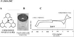
도 24A-24C. (A) 디메틸피페리딘 사이클로프로페늄의 분자 구조. (B) 글로브박스 밖에서 3 개월 및 적색 색상에 의해 나타나는 바와 같이 여전히 충전됨. (C) 이들 화합물로 구성된 배터리의 개방 회로 전압을 나타내는 스피로-프탈아미드 및 디메틸피페리딘 TAC의 순환 전압전류도.
도 25A-25C. 디메틸피페리딘 사이클로프로페늄은 [PDI][TFSI] 2 와 짝을 지어 H-셀 배터리를 생성했다. 전압 (A), 방전 용량 (B), 및 쿨롱 효율 (C)이 측정되었다.
도 26. 나프탈렌 디이미드 (NDI)의 분자 구조.
도 27A-27C. 디메틸피페리딘 사이클로프로페늄은 또한 트리에틸암모늄 테일 NDI 나프탈렌 디이미드 (NDI)와 짝을 지어 H-셀 배터리를 생성했다. 전압 (A), 방전 용량 (B), 및 쿨롱 효율 (C)이 측정되었다.
도 28A-28C. (C)의 전해질을 포함하는 배터리의 쿨롱 효율 (A) 및 전압 프로파일 (B) .
도 29. 여러 상이한 사이클로프로페늄의 전압 프로파일.
도 30. 고 에너지 밀도 유동 배터리를 달성하기 위해 용매 대신 사용될 이온성 액체.
도 31. 고전압 배터리에서 사용된 전해질의 분자 구조.
도 32. 테트라부틸 암모늄 염 사용 시의 전압 프로파일. FIG. 1 . Overall molecular structure of [PDI] 2+ and [Fc 4 ] .
FIG. 2 . Scheme S1: Synthesis of [Fc 4 ] .
Figure 3. Scheme S2: Synthesis of [PDI] [TFSI] 2
FIG. 4 . 1 H NMR (top) and 13 C NMR spectrum (bottom) of [Fc 4 ] .
FIG. 5 . 1 H NMR (top) and 13 C NMR spectrum (bottom) of [PDI] [TFSI] 2 .
Figures 6A-6C. (A) Schematic diagram of redox flow battery. (B) The structure of the active electrolyte used in this example. (C) Schematic diagram showing the state of charge and discharge of the electrolyte and an exemplary battery.
Figures 7A-7F . (A) Cyclic voltammetry of [Fc 4 ] and [PDI] [TFSI] 2 . (B, C) Battery [PDI] 0 | [PDI] 2+ || [Fc 4 ] 4 + | Cycling data for [Fc 4 ] 0 (2.42 mM / 1.14 mM). (B) Charging (bottom hollow circles) / discharge (bottom filled circles) cycling over 50 cycles at 1 C (1.6 mA / cm 2 ) in static cells as shown in the figure. Coulomb efficiency (top circle) is also plotted as shown in the figure. (C) Selected charge and discharge profiles. (D) Cycling data for low concentration cells assembled using 1.17 mM [Fc 4 ] and 1.8 mM [PDI] [TFSI] 2 . (E) Cycling data for high concentration cells using 0.4 M electron equivalents (0.2 M [PDI] [TFSI] 2 and 0.1 M [Fc 4 ]). (F) Raw data of repeated cycling shown in FIG. 7B.
8A-8B . (A) Capacity and Coulomb efficiency at different current densities, expressed in mA / cm 2 . (B) Capacity as a function of potential for selected charge and discharge cycles at different current densities.
9A-9D. [PDI] [TFSI] 2 And HPF cells with LiPF 6 were treated with (A) sodium naphthalenide and (B) NOBF 4 followed by dialysis for 15 h. (C, D) Cycling data of H-cells assembled with membranes treated under the following conditions: sodium naphthalenide (circle), NOBF 4 (square), 110 ° C (triangle) and -20 ° C (rhombus). (C) Capacity was measured as mAh; (D) Capacity was measured as mAh. For each condition, the plotted upper symbol indicates coulomb efficiency, and the plotted lower symbol indicates charge (hollow beam) / discharge (filled) measurements.
Fig. 10 . Molar absorbance of [PDI] [TFSI] 2 in acetonitrile plotted against wavelength (11 μM, 1 cm path length).
Figure 11. UV-Vis absorbance spectrum of the [Fc 4 ] side of the H-cell from the membrane stability experiment. The broad peak at ˜625 in the NOBF4-treated membrane spectrum arises from the presence of oxidized [Fc 4 ].
Figures 12A-12E . Photograph of H-cell with [PDI] [TFSI] 2 and LiPF 6 in acetonitrile on one side and blank acetonitrile on the other. (A) Control group after 12 days. (B) H-cell with membrane heated to 110 ° C. after 15 h. (C) The H-cell where the membrane was cooled to -20 ° C after 15 h. (D) H-cell with sodium naphthalenide-treated membrane after 15 h. (E) H-cell with NOBF 4 -treated membrane after 15 h.
13. Absorbance of the blank side and [ Fc 4 ] side plotted against wavelength.
Figures 14A-14B. Cycling data for battery [PDI] 0 | [PDI] 2+ || [Fc 4 ] 4+ | [Fc 4 ] 0 (2.42 mM / 1.14 mM) using 0.5 M LiPF 6 as the supporting electrolyte. (A) Repeated charge (bottom hollow circle) / discharge (bottom filled circle) cycling over 50 cycles at 1 C (1.6 mA / cm2) in a static cell. (B) Selected charge and discharge profiles.
Figure 15. Different charges for battery [PDI] 0 | [PDI] 2+ || [Fc 4 ] 4+ | [Fc 4 ] 0 (2.42 mM / 1.14 mM) using 0.5 M LiPF6 as supporting electrolyte Of the cell's open circuit voltage (OCV).
16. Charge and discharge profiles selected for low concentration cells assembled using 1.8 mM [Fc4] and 1.17 mM [PDI] [TFSI] 2 .
17. Charge and discharge profiles selected for high concentration cells assembled using 0.1 mM [Fc 4 ] and 0.2 mM [PDI] [TFSI] 2 .
Figures 18A-18B . Cycling data including discharge capacity (A) and coulomb efficiency (B) in NaCl aqueous batteries.
Figure 19. Exemplary synthetic scheme for spiro-fusion compounds
20. Molecular structure of an exemplary spiro-phthalamide compound.
Figure 21. Capacity as a function of cycle.
22. Voltage profile of ethyl-spiro-phthalamide battery.
23. 1 H NMR of the depicted spiro molecule showing no degradation after 1 week of filling.
Figures 24A-24C. (A) Molecular structure of dimethylpiperidine cyclopropenium. (B) 3 months outside the glovebox and still charged as indicated by the red color. (C) Cyclic volt-current diagrams of spiro-phthalamide and dimethylpiperidine TAC, representing the open circuit voltage of a battery composed of these compounds.
Figures 25A-25C. Dimethylpiperidine cyclopropenium was paired with [PDI] [TFSI] 2 to produce an H-cell battery. Voltage (A), discharge capacity (B), and coulomb efficiency (C) were measured.
26. Molecular structure of naphthalene diimide (NDI).
Figures 27A-27C. Dimethylpiperidine cyclopropenium was also paired with triethylammonium tail NDI naphthalene diimide (NDI) to produce an H-cell battery. Voltage (A), discharge capacity (B), and coulomb efficiency (C) were measured.
Figures 28A-28C. (C) Coulomb efficiency (A) and voltage profile (B) of a battery comprising electrolyte.
29. Voltage profiles of several different cyclopropeniums.
Fig. 30 . Ionic liquid to be used instead of solvent to achieve high energy density flow battery.
Figure 31. Molecular structure of electrolyte used in high voltage batteries.
32. Voltage profile when using tetrabutyl ammonium salt.
상세한 설명details
본 발명은 유기 전해질(예를 들어, 방향족 이미드, 페로센, 스피로 융합 화합물, 또는 사이클로프로페늄 화합물) 및 산화환원 유동 배터리 및 이를 포함하는 시스템을 제공한다. 특정 구체예에서, 방향족 이미드는 페릴렌 디이미드 트리플루오로메탄 설폰이미드 ([PDI][TFSI] 2 ) 또는 나프탈렌 디이미드, 및 이들의 유도체이다. 본 발명은 산화환원 유동 배터리에서 사용하기 위한 스피로-융합 유기 화합물을 추가로 제공한다. The present invention provides organic electrolytes (eg, aromatic imides, ferrocenes, spiro fusion compounds, or cyclopropenium compounds) and redox flow batteries and systems comprising them. In certain embodiments, the aromatic imide is perylene diimide trifluoromethane sulfonimide ( [PDI] [TFSI] 2 ) or naphthalene diimide, and derivatives thereof. The present invention further provides spiro-fused organic compounds for use in redox flow batteries.
특정 구체예에서, 본원에 개시된 유기 전해질은 수성 산화환원 유동 배터리에서 사용될 수 있다. 배터리 시스템에서 사용하기 위하여 비교적 저렴한 비용으로 인해 용매로서 물이 바람직할 수 있다. 따라서, 수성 산화환원 유동 배터리는, 예를 들어 공간이 문제가 되지 않는 (예를 들어, 그리드-스케일 배터리) 산업 규모 배터리로서 사용하기에 적합할 수 있다. 특정 구체예에서, 본원에 개시된 유기 전해질은 비수성 산화환원 유동 배터리와 함께 사용될 수 있다. 비수성 산화환원 유동 배터리는 특정한 수성 배터리 시스템과 비교하여 더 큰 전압 익스커션(excursion)(예를 들어, 3V 초과) 및 더 넓은 온도 범위(-20 내지 110 ℃)로써 사용될 수 있다. In certain embodiments, the organic electrolytes disclosed herein can be used in aqueous redox flow batteries. Water may be preferred as a solvent due to its relatively low cost for use in battery systems. Thus, an aqueous redox flow battery may be suitable for use as an industrial scale battery, for example where space is not an issue (eg, a grid-scale battery). In certain embodiments, the organic electrolytes disclosed herein can be used with non-aqueous redox flow batteries. Non-aqueous redox flow batteries can be used with larger voltage excursions (eg, greater than 3V) and a wider temperature range (-20 to 110 ° C) compared to certain aqueous battery systems.
한 양태에서, 본 발명은 산화환원 유동 배터리에서 사용하기 위한 신규한 유기 전해질을 제공한다. 본원에 개시된 유기 전해질은 긴 수명의 산화환원 유동 배터리에 안정성을 제공할 수 있다. 본원에서 사용된 용어 “긴 수명”은 반복된 충전 및 방전 사이클 동안 안정한 용량 유지력을 갖는 배터리를 지칭한다. 특정 구체예에서, 쿨롱 효율이 용량 유지력의 지표로서 사용된다. 특정 구체예에서, 긴 수명 배터리는 년 시간 규모에서 안정한 배터리를 지칭한다.In one aspect, the present invention provides a novel organic electrolyte for use in redox flow batteries. The organic electrolytes disclosed herein can provide stability to long-lived redox flow batteries. As used herein, the term “long life” refers to a battery with stable capacity retention during repeated charge and discharge cycles. In certain embodiments, coulomb efficiency is used as an indicator of capacity retention. In certain embodiments, a long life battery refers to a battery that is stable on a year time scale.
특정 구체예에서, 본 발명은 용매 및 전해질을 포함하는 전해질 용액을 제공한다. 특정 구체예에서, 전해질은 광범위한 전압을 달성하기 위해 전기화학적 특성을 조정하기 위해 합성적으로 변성된다. 특정 구체예에서, 전해질은 멤브레인을 가로지르지 못하게 하기 위해 큰 수력학적 반경을 갖도록 설계되고 합성된다. In certain embodiments, the present invention provides an electrolyte solution comprising a solvent and an electrolyte. In certain embodiments, the electrolyte is synthetically modified to adjust the electrochemical properties to achieve a wide range of voltages. In certain embodiments, the electrolyte is designed and synthesized to have a large hydraulic radius to prevent crossing the membrane.
특정 구체예에서, 전해질은 방향족 이미드이다. 특정 구체예에서, 방향족 이미드는 페릴렌 디이미드 (PDI), 또는 나프탈렌 디이미드, 또는 이들의 유도체이다. 특정 구체예에서, 전해질? 페릴렌 디이미드 트리플루오로메탄 설폰이미드 ([PDI][TFSI] 2 )이다 . 특정 구체예에서, 전해질은 페로센 유도체이다. 특정 구체예에서, 페로센 유도체는 테트라페로센 [Fc 4 ]이다. [PDI][TFSI] 2 및 [Fc 4 ]의 분자 구조가 도 1에 나타난다. In certain embodiments, the electrolyte is an aromatic imide. In certain embodiments, the aromatic imide is perylene diimide (PDI), or naphthalene diimide, or derivatives thereof. In certain embodiments, electrolytes? Perylene diimide trifluoromethane sulfonimide ( [PDI] [TFSI] 2 ) . In certain embodiments, the electrolyte is a ferrocene derivative. In certain embodiments, the ferrocene derivative is tetraferrocene [Fc 4 ] . [PDI] [TFSI] 2 and The molecular structure of [Fc 4 ] is shown in FIG. 1.
특정 구체예에서, [PDI][TFSI] 2 및 [Fc 4 ]는 음성 및 양성 반쪽 셀을 위한 활성 성분으로서 합성될 수 있다. [PDI][TFSI] 2 는 접근 가능한 2-전자 환원 상태, 전기화학적 안정성 및 간단한 유도체화로 인하여, 글리콜 사슬을 갖는 이중 테트라-알킬 암모늄 염으로서 합성될 수 있으며, 향상된 용해도를 달성한다. 유기금속 산화환원 화학에서 흔히 사용되는 페로센은, 산화-환원 쌍을 가질 수 있고 유도체화될 수 있다. [Fc 4 ]는 디글라임 중에서 점성 오일일 수 있는 덴드리머 유사 테트라페로센 화학종으로서 합성될 수 있다. [Fc 4 ]의 덴드리머 유사 구조는 이의 멤브레인을 횡단하는 능력을 감소시킬 수 있다. [Fc 4 ] 및 [PDI][TFSI] 2 의 예시적인 합성 도식이 도 2 및 3에 나타나고, [Fc 4 ] 및 [PDI][TFSI] 2 의 예시적인 NMR 스펙트럼이 도 4 및 5에 나타난다.In certain embodiments, [PDI] [TFSI] 2 and [Fc 4 ] can be synthesized as active ingredients for negative and positive half cells. [PDI] [TFSI] 2 can be synthesized as a double tetra-alkyl ammonium salt with a glycol chain, due to its accessible 2-electron reduction state, electrochemical stability and simple derivatization, achieving improved solubility. Ferrocene, commonly used in organometallic redox chemistry, can have an oxidation-reduction pair and can be derivatized. [Fc 4 ] can be synthesized as a dendrimer-like tetraferrocene species that can be a viscous oil in diglyme. The dendrimer-like structure of [Fc 4 ] can reduce its ability to cross the membrane. Exemplary synthetic schemes of [Fc 4 ] and [PDI] [TFSI] 2 are shown in FIGS. 2 and 3, and exemplary NMR spectra of [Fc 4 ] and [PDI] [TFSI] 2 are shown in FIGS. 4 and 5.
또 다른 양태에서, 본 발명은 환원전극액을 포함하는 환원전극 셀; 산화전극액을 포함하는 산화전극 셀을 포함하는 산화환원 유동 배터리를 제공하고, 여기서 환원전극액 및 산화전극액 중 적어도 하나는 본원에 개시된 유기 전해질을 포함한다. 특정 구체예에서, 산화전극액은 PDI의 유도체를 포함한다. 특정 구체예에서, PDI 유도체는 [PDI][TFSI] 2 이다. 특정 구체예에서, 환원전극액은 페로센 유도체를 포함한다. 특정 구체예에서, 페로센 유도체는 [Fc 4 ]이다. 특정 구체예에서, 산화환원 유동 배터리는 환원전극 및 환원전극액을 포함하는 환원전극 셀; 산화전극 및 산화전극액을 포함하는 산화전극 셀을 포함하고, 여기서 산화전극액은 [PDI][TFSI] 2 이고 환원전극액은 [Fc 4 ]이다. In another aspect, the present invention is a cathode electrode cell comprising a cathode electrode solution; Provided is a redox flow battery comprising an anode cell comprising an anode solution, wherein at least one of the cathode and anode solutions comprises the organic electrolyte disclosed herein. In a specific embodiment, the electrode solution comprises a derivative of PDI. In certain embodiments, the PDI derivative is [PDI] [TFSI] 2 . In certain embodiments, the cathode electrode solution includes a ferrocene derivative. In certain embodiments, the ferrocene derivative is [Fc 4 ] . In a specific embodiment, the redox flow battery comprises a cathode electrode cell comprising a cathode electrode and a cathode electrode solution; It includes an anode electrode cell including an anode electrode and an anode electrode solution, wherein the anode electrode solution is [PDI] [TFSI] 2 and the cathode electrode solution is [Fc 4 ] .
특정 구체예에서, 본원에 개시된 산화환원 유동 배터리는 환원전극 및 산화전극을 추가로 포함한다. 특정 구체예에서, 환원전극은 카본 펠트 전극 또는 카본 페이퍼 전극이다. 특정 구체예에서, 산화전극은 카본 펠트 전극 또는 카본 페이퍼 전극이다. 특정 구체예에서, 산화환원 유동 배터리는 환원전극 셀과 산화전극 셀 사이에 배치된 분리막으로서 멤브레인을 추가로 포함한다. 당해 분야에서 공지인 임의의 적합한 멤브레인이 본 발명에 사용될 수 있다. 특정 구체예에서, 멤브레인은 이온 교환 멤브레인이다. 특정 구체예에서, 멤브레인은 미국 가출원 제62/699,489호에 개시된 멤브레인이다.In certain embodiments, redox flow batteries disclosed herein further include a cathode and an anode. In certain embodiments, the cathode is a carbon felt electrode or a carbon paper electrode. In a specific embodiment, the anode is a carbon felt electrode or a carbon paper electrode. In certain embodiments, the redox flow battery further includes a membrane as a separator disposed between the cathode electrode cell and the anode cell. Any suitable membrane known in the art can be used in the present invention. In certain embodiments, the membrane is an ion exchange membrane. In certain embodiments, the membrane is a membrane disclosed in US Provisional Application No. 62 / 699,489.
도 6A에 나타나는 본 발명의 구체예에 따른 산화환원 유동 배터리는 산화전극액(11) ([PDI][TFSI] 2 ) 및 산화전극(41)을 포함하는 산화전극 셀(1), 환원전극액(21) ([Fc 4 ]) 및 환원전극(42)를 포함하는 환원전극 셀(2), 및 산화전극 셀(1)과 환원전극 셀(2) 사이에 배치된 멤브레인(10)을 포함한다. 산화전극액(11) 및 환원전극액(21)은 각각 펌프(31) 및 (32)를 통해 순환할 수 있다. 충전 및 방전은 이온의 산화 상태 변화에 따라 산화전극(41) 및 환원전극(42)에서 일어난다. 이온 교환 멤브레인(10)은 환원전극액(11) 및 산화전극액(12)의 활성 물질의 이온이 서로 혼합되는 것을 방지하고 지지 전해질의 전하 운반체의 이온만이 전달되도록 한다. [PDI][TFSI] 2 및 [Fc 4 ]에 대한 산화환원 반응은 도 6A의 삽도에서 충전 및 방전에 대해 나타난다. 산화전극액(11) 및 환원전극액(12)의 분자 구조 및 충전/방전 반응은 도 6B-6C에 나타난다. 특정 구체예에서, 산화환원 유동 배터리는 전극으로서 카본 펠트를 포함하는 정적 셀에 있다 (예를 들어, H-셀 구성, 비제한적 구체예 H-셀 구성 및 음극 및 양극에서 일어나는 산화환원 반응에 대한 도 6C 참조). The redox flow battery according to the embodiment of the present invention shown in FIG. 6A is an anode cell (1), a cathode electrode solution comprising an anode electrode (11) ( [PDI] [TFSI] 2 ) and an anode 41 (21) ( [Fc 4 ]) and a
전해질로서 [Fc 4 ] 및 [PDI][TFSI] 2 및 지지 전해질로서 0.1 M LiPF6을 사용하는 예시적인 배터리에서, 배터리의 안정성이 측정되었다. 4:1 MeCN:THF에서 50 mV/s로 순환 전압전류를 스캔했다 (도 7A). 정적 셀에서 1 C (1.6 mA/cm2)에서 50 사이클에 걸쳐 반복된 충전 /방전 사이클링의 용량은 0 내지 1.2 V에서 제한된 전압으로써 측정되었다 (도 7B). 선형 피팅(fitting)은 방전 용량에 대해 사이클당 0.0453%의 페이드(fade)를 나타내는 기울기를 얻었다. 쿨롱 효율은 99.954%의 평균을 가졌고 (도 7B), 셀 개방 회로 전압(OCV)이 또한 다른 충전 상태에서 측정되었다 (도 7B 삽도). 선택된 충전 및 방전 프로파일이 도 7C에 제시되었고, 이는최초 40 사이클 동안 작은 변화를 나타내며 여기서 ~87% SOC의 초기 용량이 대략 사이클 40에서 ~81% SOC로 안정된다. In an exemplary battery using [Fc 4 ] and [PDI] [TFSI] 2 as the electrolyte and 0.1 M LiPF 6 as the supporting electrolyte, the stability of the battery was measured. Cyclic voltage currents were scanned at 50 mV / s at 4: 1 MeCN: THF (Figure 7A). The capacity of charge / discharge cycling repeated over 50 cycles at 1 C (1.6 mA / cm 2 ) in a static cell was measured as a limited voltage from 0 to 1.2 V (FIG. 7B). The linear fitting obtained a slope showing a fade of 0.0453% per cycle with respect to the discharge capacity. Coulomb efficiency had an average of 99.954% (Figure 7B), and the cell open circuit voltage (OCV) was also measured at different charge states (Figure 7B inset). The selected charge and discharge profile is shown in Figure 7C, which shows a small change over the first 40 cycles where the initial capacity of ~ 87% SOC is stabilized to approximately -81% SOC at approximately 40 cycles.
1.17 mM [Fc4] 및 1.8 mM [PDI][TFSI]2를 사용하여 조립된 저농도 셀이 생성되었고, 교반되는 H-셀에서 1 C (1.16 mA/cm2)에서 230 사이클에 걸친 충전 및 방전 과정에 대한 용량 유지력이 측정되었다 (도 7D). 초기의 작은 용량 감소 후, 충전 및 방전 용량은 사이클 40 후 안정되었다. 40으로부터 235까지 이 데이터를 선형 피팅하여, 방전 용량에 대해 사이클당 0.00614%의 페이드를 나타내는 기울기를 얻었다. 쿨롱 효율이 또한 플로팅되었고 99.955%의 평균을 갖는다. 사이클링은 충전된 상태에서 11 동안 정지되었다. 최초의 방전 (화살표로 표시된 마름모) 및 후속 사이클링은 무시할 만한 용량 손실을 나타냈다. 0.4 M 전자 당량(0.2 M [PDI][TFSI]2 및 0.1 M [Fc4])을 사용하는 고농도 셀이 또한 생성되었다. 충전(하부 속이 빈 사각형) 및 방전(하부 채워진 사각형) 용량이 74 일 초과의 작동에 해당하는 >450 사이클에 대해 나타났다 (도 7E). 사이클 5 초과의 평균 CE(상부 속이 빈 사각형)는 99.868%이었다. 두 가지 셀에서 (도 7D 및 7E), Li[TFSI]은 지지 전해질로서 사용되었고, 전압은 0 내지 1.2 V에서 제한되었다. 도 7D 및 7E의 삽도는 대응하는 셀에 대해 선택된 충전 및 방전 프로파일을 나타냈다. 예시적인 구체예에서, 배터리는 전하 균형 염으로서 0.5 M LiPF6과 함께 아세토니트릴/디글라임의 혼합물(10:1) 중의 2.42 mM [PDI][TFSI] 2 및 1.14 mM [Fc 4 ]를 포함했다. 1 C 전류(1.7 mA/cm2)에서 안정된 후, 전류 밀도는 0.3 C (0.5 mA/cm2)까지 강하하고 도 8A-8B에 나타난 값까지 계단식으로 증가했다. Low concentration cells assembled using 1.17 mM [Fc 4 ] and 1.8 mM [PDI] [TFSI] 2 were produced and charged and discharged over 230 cycles at 1 C (1.16 mA / cm2) in a stirred H-cell. The capacity retention capacity for was measured (FIG. 7D). After the initial small capacity reduction, the charge and discharge capacity stabilized after
특정 구체예에서, 멤브레인은 투석 및 크기 배제 멤브레인이다. 특정 구체예에서, 멤브레인은 셀룰로스로 만들어진다. 멤브레인은 산화전극액과 환원전극액을 분리하고 넓은 범위의 전압(예를 들어, 약 3V 초과) 및 온도(예를 들어, 약 -20 ℃ 내지 약 110 ℃)에서 활성 성분의 횡단을 방지한다. In certain embodiments, the membrane is a dialysis and size exclusion membrane. In certain embodiments, the membrane is made of cellulose. The membrane separates the anode and cathode solutions and prevents crossing of the active ingredient over a wide range of voltages (eg, greater than about 3V) and temperatures (eg, about -20 ° C to about 110 ° C).
특정 구체예에서, 멤브레인을 소듐 나프탈레나이드의 용액(대략 -3.0 V vs Fc0/+)에 담그고 이어서 이 멤브레인을 사용하여 H-셀을 조립했다. H-셀의 한 챔버를 아세토니트릴 중의 [PDI][TFSI] 2 로 채우는 한편, 다른 챔버는 순수한 아세토니트릴을 수용했다. [PDI][TFSI] 2 는 작은 크기 및 강한 흡수로 인해 횡단 실험에 사용되었다. 밤새 교반한 후, [PDI][TFSI] 2 의 검출 가능한 횡단이 눈에 띄게 관찰되지 않았다 (도 9A). 강한 산화 (NOBF4, 대략 0.9 V vs Fc0/+) 조건은 유사한 결과를 나타냈지만 [PDI][TFSI] 2 의 횡단으로부터 약한 형광이 있었다 (도 9B). 사이클링은 아마도 활성 전해질의 횡단으로 인한 작은 단조 페이드를 나타냈다 (도 9C-9D). In a specific embodiment, the membrane was immersed in a solution of sodium naphthalenide (approximately -3.0 V vs Fc 0 / + ) and then the membrane was used to assemble the H-cell. One chamber of the H-cell was filled with [PDI] [TFSI] 2 in acetonitrile, while the other chamber received pure acetonitrile. [PDI] [TFSI] 2 was used in transverse experiments due to its small size and strong absorption. After stirring overnight, no detectable crossing of [PDI] [TFSI] 2 was noticeably observed (FIG. 9A). Strong oxidation (NOBF 4 , approximately 0.9 V vs Fc 0 / + ) conditions showed similar results, but there was weak fluorescence from crossing [PDI] [TFSI] 2 (FIG. 9B). Cycling showed a small forging fade probably due to the crossing of the active electrolyte (FIGS. 9C-9D).
특정 구체예에서, 이온 교환은 멤브레인을 통해 산화전극액과 환원전극액 사이에서 일어난다. 일부 구체예에서, 멤브레인은 환원 또는 산화 조건에서 작동할 수 있다. 예를 들어, 멤브레인은 소듐 나프탈레나이드 또는 무수 디글라임 용액에 대한 노출 약 4 시간 후 활성 성분의 횡단을 방지할 수 있다 (12 일에 걸쳐 0.05%, 도 10 및 11).In certain embodiments, ion exchange occurs between the anode and cathode solutions through the membrane. In some embodiments, the membrane can operate in reducing or oxidizing conditions. For example, the membrane can prevent crossing of the active ingredient after about 4 hours of exposure to sodium naphthalenide or anhydrous diglyme solutions (0.05% over 12 days, FIGS. 10 and 11).
도 12A-12E에 나타나는 한 구체예에서, 멤브레인 안정성이 산화전극 셀(1)에서의 아세토니트릴 및 환원전극 셀(2)에서의 블랭크 아세토니트릴 중의 [PDI][TFSI] 2 및 LiPF6을 갖는 H-셀에서 측정되었고 멤브레인(10)은 그 사이에 배치되었다. (12B) 15 h 후 110 ℃까지 가열된 멤브레인, (12C) 15 h 후 -20 ℃까지 냉각된 멤브레인, (12D) 15 h 후 소듐 나프탈레나이드-처리된 멤브레인을 갖는 H-셀, 및 (12E) 15 h 후 NOBF4-처리된 멤브레인을 갖는 H-셀을 포함하는 상이한 조건이 테스트되었다. 멤브레인은 고온(110 ℃) 및 저온(-20 ℃)에서 안정한 것으로 밝혀졌다 (도 11)In one embodiment shown in FIGS. 12A-12E, the membrane stability is H with [PDI] [TFSI] 2 and LiPF 6 in acetonitrile in the
한 구체예에서, 중성 상태의 [Fc 4 ] 분자의 횡단이 31 mg을 THF에 용해시키고 이 용액을 3.5 kDa 멤브레인과 다른 쪽의 블랭크 THF를 갖는 H-셀의 한 쪽에 넣어 모니터링되었다 (도 13). [Fc 4 ]의 몰 흡광도(439 nm에서 423.67 M-1 cm-1)를 사용하여, 횡단은 0.60%인 것으로 밝혀졌다 (도 13). 비교하면, 비치환 단량체 페로센은 1 kDa 멤브레인을 통해 밤새 확산되었다. In one embodiment, crossing of the neutral [Fc 4 ] molecule was monitored by dissolving 31 mg in THF and placing this solution in one side of an H-cell with a 3.5 kDa membrane and the other side blank THF (FIG. 13). . Using a molar absorbance of [Fc 4 ] (423.67 M −1 cm −1 at 439 nm), the crossing was found to be 0.60% (FIG. 13). In comparison, unsubstituted monomer ferrocene diffused through the 1 kDa membrane overnight.
특정 구체예에서, 산화환원 유동 배터리는 지지 전해질을 추가로 포함한다. 특정 구체예에서, 지지 전해질은 전기 전도성을 향상시키는 리튬 헥사플루오로포스페이트(LiPF6)이다. 특정 구체예에서, 지지 전해질은 전기 전도성을 향상시키는 리튬 비스트리플루오로메탄설폰이미드(LiTFSI)이다. 특정 구체예에서, 지지 전해질은 멤브레인을 통과할 수 있고 유기 용매에서 전기 전도성을 가질 수 있다. 장기 안정성 배터리 사이클링이 전하 균형 염으로서 0.5 M LiPF6을 사용하여 조사되었고 (도 14A-14B), 배터리는 [PDI] 0 |[PDI] 2+ ||[Fc 4 ] 4+ |[Fc 4 ] 0 (2.42 mM/1.14 mM)를 포함한다. 전압은 0 내지 1.2 V에서 제한되었다. 쿨롱 효율(청색 원)이 또한 플로팅되었고 99.954%의 평균을 갖는다 (도 14A). 또한, 더 높은 출력 전압을 향한 방전 곡선의 약간의 이동이 있으며, 이는 더 높은 출력을 의미한다. 도 15는 지지 전해질로서 0.5 M LiPF6을 사용하는 배터리 [PDI] 0 |[PDI] 2+ ||[Fc 4 ] 4+ |[Fc 4 ] 0 (2.42 mM/1.14 mM)에 대해 상이한 충전 상태에서의 셀 개방 회로 전압(OCV)을 나타냈다. 도 16은 1.8 mM [Fc4] 및 1.17 mM [PDI][TFSI] 2 을 사용하여 조립된 저농도 셀에 대해 선택된 충전 및 방전 프로파일을 나타냈다. 0.5 M Li[TFSI]이 지지 전해질로서 사용되었다. 도 7D 삽도에 나타나는 것과 동일한 데이터. 도 17은 0.1 mM [Fc 4 ] 및 0.2 mM [PDI][TFSI] 2 를 사용하여 조립된 고농도 셀에 대해 선택된 충전 및 방전 프로파일을 나타냈다. 0.5 M Li[TFSI]이 지지 전해질로서 사용되었다. 도 7E 삽도에 나타나는 것과 동일한 데이터. In certain embodiments, the redox flow battery further comprises a supporting electrolyte. In certain embodiments, the supporting electrolyte is lithium hexafluorophosphate (LiPF6), which enhances electrical conductivity. In certain embodiments, the supporting electrolyte is lithium bistrifluoromethanesulfonimide (LiTFSI), which enhances electrical conductivity. In certain embodiments, the supporting electrolyte can pass through the membrane and have electrical conductivity in an organic solvent. Long-term stability battery cycling was investigated using 0.5 M LiPF6 as the charge balance salt (FIGS. 14A-14B), and the battery was [PDI] 0 | [PDI] 2+ || [Fc 4 ] 4+ | [Fc 4 ] 0 (2.42 mM / 1.14 mM). The voltage was limited from 0 to 1.2 V. Coulomb efficiency (blue circle) was also plotted and has an average of 99.954% (FIG. 14A). Also, there is a slight shift of the discharge curve towards a higher output voltage, which means higher output. FIG. 15 shows different charge states for batteries [PDI] 0 | [PDI] 2+ || [Fc 4 ] 4+ | [Fc 4 ] 0 (2.42 mM / 1.14 mM) using 0.5 M LiPF6 as the supporting electrolyte. The cell open circuit voltage (OCV). 16 shows the selected charge and discharge profiles for low concentration cells assembled using 1.8 mM [Fc4] and 1.17 mM [PDI] [TFSI] 2 . 0.5 M Li [TFSI] was used as supporting electrolyte. Same data as shown in Figure 7D inset. 17 shows selected charge and discharge profiles for high concentration cells assembled using 0.1 mM [Fc 4 ] and 0.2 mM [PDI] [TFSI] 2 . 0.5 M Li [TFSI] was used as supporting electrolyte. Same data as shown in Figure 7E inset.
당해 분야에서 공지인 임의의 적합한 용매가 본 발명에 사용될 수 있다. 특정 구체예에서, 유기 용매는 비수성 용매이다. 비수성 용매의 비제한적 예는 디에틸 카보네이트, 디메틸 카보네이트, 아세토니트릴, γ-부티로락톤(GBL), 프로필렌 카보네이트(PC), 에틸렌 카보네이트(EC), N-메틸-2-피롤리돈(NMP), 플루오로에틸렌 카보네이트, N,N-디메틸아세트아미드, 설파론, 트리플루오로톨루엔 또는 이들의 혼합이다. 특정 구체예에서, 용매는 수성 용매이다. 특정 구체예에서, 수성 용매는 물을 포함한다. 특정 구체예에서, 수성 용매는 염을 추가로 포함한다. 염의 비제한적 예는 NaCl, KCl, MgCl2, CaCl2, 및 LiCl로 이루어진 군에서 선택된다. Any suitable solvent known in the art can be used in the present invention. In certain embodiments, the organic solvent is a non-aqueous solvent. Non-limiting examples of non-aqueous solvents are diethyl carbonate, dimethyl carbonate, acetonitrile, γ-butyrolactone (GBL), propylene carbonate (PC), ethylene carbonate (EC), N-methyl-2-pyrrolidone (NMP) ), Fluoroethylene carbonate, N, N-dimethylacetamide, sulfonone, trifluorotoluene, or mixtures thereof. In certain embodiments, the solvent is an aqueous solvent. In certain embodiments, aqueous solvents include water. In certain embodiments, the aqueous solvent further comprises a salt. Non-limiting examples of salts are selected from the group consisting of NaCl, KCl, MgCl 2 , CaCl 2 , and LiCl.
특정 구체예에서, 산화환원 유동 배터리는 반복하여 충전 및 방전되는 동안 안정하다. 특정 구체예에서, 본원에 개시된 산화환원 유동 배터리는, 일정한 1C (1.6 mA/cm2) 전류에서, 92% 충전 상태에 도달할 수 있고, 이는 80% 초과이며 사이클링 안정성을 나타낸다. 용매로서 물 중의 0.5 M NaCl, 산화전극액으로서 PDI, 및 환원전극액으로서 페로센을 포함하는 예시적인 수성 배터리에서, 사이클링 데이터는 이것이 > 99.99% 용량 유지력, 및 > 99.99% 쿨롱 효율을 가짐을 나타냈다 (도 18A-18B). 특정 구체예에서, 본원에 개시된 산화환원 유동 배터리는 충전 및 방전 사이클 동안 안정한 용량 유지력을 갖는다. 특정 구체예에서, 쿨롱 효율은 용량 유지력의 지표로서 사용되고, 여기서 쿨롱 효율은 전자가 전기화학 반응을 용이하게 하는 시스템으로 전달되는 효율을 기술한다. 특정 구체예에서, 본원에 개시된 산화환원 유동 배터리의 쿨롱 효율은 500 충전 및 방전 사이클 및 약 75 일에 걸쳐 각 사이클에서 약 99%에 근접한다.In certain embodiments, the redox flow battery is stable during repeated charging and discharging. In certain embodiments, the redox flow batteries disclosed herein can reach a 92% charge state at a constant 1C (1.6 mA / cm2) current, which is greater than 80% and exhibits cycling stability. In an exemplary aqueous battery comprising 0.5 M NaCl in water as a solvent, PDI as an anode solution, and ferrocene as a cathode solution, cycling data showed that it had> 99.99% capacity retention and> 99.99% coulomb efficiency ( Figures 18A-18B). In certain embodiments, the redox flow batteries disclosed herein have stable capacity retention during charge and discharge cycles. In certain embodiments, coulomb efficiency is used as an indicator of capacity retention, where coulomb efficiency describes the efficiency with which electrons are delivered to a system that facilitates an electrochemical reaction. In certain embodiments, the coulomb efficiency of a redox flow battery disclosed herein is close to about 99% in each cycle over 500 charge and discharge cycles and about 75 days.
또 다른 양태에서, 본 발명은 배터리에서 사용하기 위한 스피로-융합 유기 화합물, 및 그러한 유기 화합물을 포함하는 배터리를 위한 시스템 및 방법을 제공한다. 특정 구체예에서, 개시된 주제는 스피로-융합 모티프를 통해 산화환원-활성 유기 분자를 연결하는 구조를 갖는 유기 화합물을 제공한다. 산화환원-활성 유기 분자는 방향족 산화환원 코어를 갖는 임의의 유기 분자일 수 있다. 특정 구체예에서, 유기 화합물은 하기 화학식 (I)로 나타나는 구조를 갖는다: In another aspect, the present invention provides spiro-fused organic compounds for use in batteries, and systems and methods for batteries comprising such organic compounds. In certain embodiments, the disclosed subject matter provides organic compounds having a structure that links redox-active organic molecules through a spiro-fusion motif. The redox-active organic molecule can be any organic molecule having an aromatic redox core. In certain embodiments, the organic compound has a structure represented by Formula (I):

특정 구체예에서, 화학식 (I) 화합물은 스피로-융합 탄소 케이지를 통한 프탈이미드 산화환원 분자 이합체화에 의해 생성될 수 있다. 본원에 개시된 스피로-융합 화합물 합성의 예시적인 방법이 도 19에 나타난다. 특정 구체예에서, 유기 화합물은 이미드 작용기와 상이한 가용화 사슬을 갖는 유도체화된 스피로-프탈이미드이다. 특정 구체예에서, R은 알킬, 에테르, 암모늄 염, 또는 임의의 가용화 사슬을 나타낸다. 특정 구체예에서, 화합물은 스피로-프탈아미드 화합물이다. 비제한적인 예시적 스피로-프탈아미드 화합물이 도 20에 나타난다. 특정 구체예에서, R은 에틸을 나타내고, 유기 화합물은 스피로-에틸프탈이미드일 수 있다. 특정 구체예에서, 유기 화합물은 스피로-에틸카테콜이다. In certain embodiments, the compound of formula (I) may be produced by phthalimide redox molecular dimerization through a spiro-fused carbon cage. An exemplary method of synthesizing spiro-fusion compounds disclosed herein is shown in FIG. 19. In certain embodiments, the organic compound is a derivatized spiro-phthalimide having a solubilizing chain different from the imide functional group. In certain embodiments, R represents an alkyl, ether, ammonium salt, or any solubilizing chain. In certain embodiments, the compound is a spiro-phthalamide compound. Non-limiting exemplary spiro-phthalamide compounds are shown in Figure 20. In certain embodiments, R represents ethyl and the organic compound can be spiro-ethylphthalimide. In certain embodiments, the organic compound is spiro-ethylcatechol.
본원에 개시된 구체예에서, 6일의 사이클링은 기기장치 및 셀 구성의 실험적 한계 내에서 용량 저하가 없음을 나타냈다 (도 21 & 22). 1 주의 충전에 걸쳐 저하가 관찰되지 않았다 (도 23). In the embodiments disclosed herein, cycling of 6 days showed no capacity degradation within the experimental limits of instrumentation and cell construction (FIGS. 21 & 22). No degradation was observed over 1 week of filling (Figure 23).
개시된 주제는 또한 용량 성능을 위한 공학기술 개선과 함께 신규한 전해질의 유기 합성을 통한 더 높은 전압 및 더 높은 용량의 산화환원 유동 배터리 개발에 관한 것이다. 또 다른 양태에서, 본 발명은 본원에 개시된 스피로-융합 유기 화합물, 또는 적합한 이의 유도체를 포함하는 산화환원 유동 배터리를 제공한다. 특정 구체예에서, 배터리는 산화전극액을 포함하고, 여기서 산화전극액은 본원에 개시된 스피로-융합 유기 화합물, 또는 적합한 이의 유도체를 포함한다. 특정 구체예에서, 배터리는 환원전극액을 추가로 포함한다. 특정 구체예에서, 환원전극액은 페로센 유도체이다. 특정 구체예에서, 페로센 유도체는 테트라페로센 [Fc 4 ]이다. The disclosed subject matter also relates to the development of higher voltage and higher capacity redox flow batteries through organic synthesis of novel electrolytes along with engineering improvements for capacity performance. In another aspect, the present invention provides a redox flow battery comprising a spiro-fused organic compound disclosed herein, or a suitable derivative thereof. In certain embodiments, the battery comprises an oxidizing electrode solution, wherein the oxidizing electrode solution comprises a spiro-fused organic compound disclosed herein, or a suitable derivative thereof. In certain embodiments, the battery further comprises a cathode electrode solution. In certain embodiments, the cathode solution is a ferrocene derivative. In certain embodiments, the ferrocene derivative is tetraferrocene [Fc 4 ] .
특정 구체예에서, 배터리는 환원전극 셀과 산화전극 셀 사이에 배치된 분리막으로서 멤브레인을 추가로 포함한다. 당해 분야에서 공지인 임의의 적합한 멤브레인이 본 발명에 사용될 수 있다. 특정 구체예에서, 멤브레인은 이온 교환 멤브레인이다. 특정 구체예에서, 멤브레인은 미국 가출원 제62/699,489호에 개시된 멤브레인이다. 특정 구체예에서, 멤브레인은 Daramic 175이다. 특정 구체예에서, 배터리는 고체-상태 배터리이다. In certain embodiments, the battery further includes a membrane as a separator disposed between the cathode and anode cells. Any suitable membrane known in the art can be used in the present invention. In certain embodiments, the membrane is an ion exchange membrane. In certain embodiments, the membrane is a membrane disclosed in US Provisional Application No. 62 / 699,489. In certain embodiments, the membrane is Daramic 175. In certain embodiments, the battery is a solid-state battery.
본원에 개시된 배터리는 특정 수성 배터리의 범위 밖의 온도 및 전압에서 작동할 수 있다. 예를 들어, 배터리는 고온 및 저온 모두에서 작동할 수 있다. 이는 북부 및 남부 기후에 유용할 수 있다. 특정 구체예에서, 본원에 개시된 배터리는 배터리의 풋프린트(footprint)를 감소시킬 수 있는 높은 전압에서 작동할 수 있다. 그러한 특징은 더 작은 배터리의 개발을 가능하게 하며, 이는 공간 한정된 응용분야에서 유용할 수 있다. 특정 구체예에서, 본원에 개시된 배터리는 도 21에 나타나는 바와 같이 용량 저하가 없다. The batteries disclosed herein can operate at temperatures and voltages outside the range of certain aqueous batteries. For example, the battery can operate at both high and low temperatures. This can be useful for northern and southern climates. In certain embodiments, the batteries disclosed herein can operate at high voltages that can reduce the footprint of the battery. Such features enable the development of smaller batteries, which can be useful in space-limited applications. In certain embodiments, the batteries disclosed herein are free of capacity degradation as shown in FIG. 21.
개시된 주제는 그리드 저장에서 에너지 생산자 또는 가정용 저장에서 대형 기기 제조업체에 의해 사용될 수 있다. 또 다른 양태에 따르면, 본 발명은 본원에 개시된 스피로-융합 유기 화합물, 또는 적합한 이의 유도체를 사용하는 배터리를 포함하는 전기 저장 시스템을 제공한다. 특정 구체예에서, 전기 저장 시스템은 대규모 전기 저장 시스템(예를 들어, 그리드 저장 시스템)일 수 있다. 특정 구체예에서, 전기 저장 시스템은 소규모 전기 저장 시스템(예를 들어, 가정용 저장 시스템)일 수 있다. The disclosed subject matter can be used by energy producers in grid storage or large equipment manufacturers in home storage. According to another aspect, the present invention provides an electrical storage system comprising a battery using the spiro-fused organic compounds disclosed herein, or suitable derivatives thereof. In certain embodiments, the electrical storage system can be a large-scale electrical storage system (eg, a grid storage system). In certain embodiments, the electrical storage system can be a small-scale electrical storage system (eg, a home storage system).
또 다른 양태에서, 본 발명은 환원전극액 전압을 증가시키기 위해 배터리에서 환원전극액으로서 사용하기 위한 사이클로프로페늄 화합물(삼각형 분자)을 제공한다. 특정 구체예에서, 사이클로프로페늄 화합물은 도 24A에 나타나는 디메틸피페리딘 사이클로프로페늄이다. 특정 구체예에서, 사이클로프로페늄 화합물은 삼각형 부분에 부착되는 고리 구조 그룹(사이클로프로페늄 이온)을 포함한다. 비제한적인 예시적 고리 그룹은 피페리딘, 및 피롤리딘, 모폴린을 포함한다. 당해 분야에 공지인 임의의 적합한 산화전극액이 배터리에 사용하기 위해 사이클로프로페늄 화합물과 짝을 지을 수 있다. 특정 구체예에서, 사이클로프로페늄 화합물은 본원에 개시된 임의의 유동 배터리에 사용하기 위해 본원에 개시된 임의의 산화전극액과 짝을 짓는다. 특정 구체예에서, 산화전극액은 [PDI][TFSI] 2 이다. 특정 구체예에서, 산화전극액은 트리에틸암모늄 테일 나프탈렌 디이미드(NDI)이다. 특정 구체예에서, 산화전극액은 본원에 개시된 스피로-융합 유기 화합물이다. In another aspect, the present invention provides a cyclopropenium compound (triangular molecule) for use as a cathode solution in a battery to increase the cathode solution voltage. In certain embodiments, the cyclopropenium compound is dimethylpiperidine cyclopropenium shown in FIG. 24A. In certain embodiments, cyclopropenium compounds include a ring structure group (cyclopropenium ion) attached to a triangular moiety. Non-limiting exemplary ring groups include piperidine, and pyrrolidine, morpholine. Any suitable electrode oxide solution known in the art can be paired with a cyclopropenium compound for use in a battery. In certain embodiments, the cyclopropenium compound is paired with any electrode solution disclosed herein for use in any flow battery disclosed herein. In a specific embodiment, the electrode solution is [PDI] [TFSI] 2 . In a specific embodiment, the electrode solution is triethylammonium tail naphthalene diimide (NDI). In certain embodiments, the electrode solution is a spiro-fused organic compound disclosed herein.
본원에 개시된 한 구체예에서, 디메틸피페리딘 사이클로프로페늄은 [PDI][TFSI] 2 와 짝을 지어 H-셀 배터리를 생성했다. 배터리는 용매로서 아세토니트릴, 및 지지 전해질로서 LiTFSI을 사용했다. 배터리는 99.63%의 쿨롱 효율 및 99.59%의 용량 유지력을 나타냈다 (도 25A-25C). 본원에 개시된 또 다른 구체예에서, 디메틸피페리딘 사이클로프로페늄은 트리에틸암모늄 테일 나프탈렌 디이미드(NDI)와 짝을 지어 H-셀 배터리를 생성했다. NDI의 분자 구조는 도 26에 나타났다. 배터리는 용매로서 아세토니트릴, 및 지지 전해질로서 LiTFSI을 사용했다. 배터리는 99.5%의 쿨롱 효율 및 99.6%의 용량 유지력을 나타냈다 (도 27A-27C). 본원에 개시된 또 다른 구체예에서, 디메틸피페리딘 사이클로프로페늄은 도 28C에 나타나는 스피로-융합 화합물과 짝을 지었다. LiTFSI는 지지 전해질로서 사용되었고, 멤브레인은 통계적으로 주 단위였다. 한 시간 충전 후, 전압 컷오프 방전이 측정되었다. OCV는 2.4V였고 완전히 충전될 경우 더 높을 수 있다. 쿨롱 효율 및 전압 프로파일이 도 28A-28B에 나타났다. In one embodiment disclosed herein, dimethylpiperidine cyclopropenium was paired with [PDI] [TFSI] 2 to produce an H-cell battery. The battery used acetonitrile as a solvent and LiTFSI as a supporting electrolyte. The battery showed 99.63% Coulomb efficiency and 99.59% capacity retention (FIGS. 25A-25C). In another embodiment disclosed herein, dimethylpiperidine cyclopropenium was paired with triethylammonium tail naphthalene diimide (NDI) to produce an H-cell battery. The molecular structure of NDI is shown in Figure 26. The battery used acetonitrile as a solvent and LiTFSI as a supporting electrolyte. The battery exhibited a Coulomb efficiency of 99.5% and a capacity retention capacity of 99.6% (FIGS. 27A-27C). In another embodiment disclosed herein, dimethylpiperidine cyclopropenium was paired with the spiro-fusion compound shown in FIG. 28C. LiTFSI was used as a supporting electrolyte, and the membrane was statistically weekly. After charging for an hour, voltage cutoff discharge was measured. OCV was 2.4V and can be higher when fully charged. Coulomb efficiency and voltage profiles are shown in FIGS. 28A-28B.
특정 구체예에서, 본원에 개시된 배터리는 용매로서 이온성 액체(예를 들어, 도 29), 및 상이한 전압을 갖는 다양한 사이클로프로페늄(예를 들어, 도 30에 나타나는 피롤리딘 TAC)을 사용하여 생성될 수 있다. In certain embodiments, batteries disclosed herein use ionic liquids (e.g., FIG. 29) as solvents and various cyclopropeniums (e.g., pyrrolidine TACs shown in FIG. 30) with different voltages. Can be created.
특정 구체예에서, 전압은 이온성 액체를 사용하여 염으로써 조작될 수 있다. 전압은 반대 이온을 조작하여 변화될 수 있다. 한 구체예에서, 배터리는 도 31에 나타나는 전해질을 사용하여 생성되었다. 이 배터리에 대해 충전 후 개방 회로 전압은 2.95 V였다 (도 32). In certain embodiments, the voltage can be manipulated as a salt using an ionic liquid. The voltage can be changed by manipulating the counter ions. In one embodiment, the battery was produced using the electrolyte shown in FIG. 31. The open circuit voltage after charging for this battery was 2.95 V (Figure 32).
실시예 배터리에서 사용된 멤브레인은 미국 가출원 제62/699,489호의 개시에 따랐다.The membrane used in the Example battery was in accordance with the disclosure of US Provisional Application No. 62 / 699,489.
실시예 Example
개시된 본 발명 주제는 제한이 아니라 개시된 본 발명 주제의 예시로서 제공된 다음의 실시예를 참조하여 더 잘 이해될 것이다.The disclosed subject matter will be better understood by reference to the following examples, which are provided by way of illustration, not limitation, of the disclosed subject matter.
실시예 1: 높은 쿨롱 효율 및 안정한 사이클링을 갖는 유동 배터리에 대한 재료 플랫폼Example 1: Material platform for flow batteries with high coulomb efficiency and stable cycling
본 실시예는 등급 안정성에서 가장 우수한 유기 매질에 용해된 모든 유기 전해질을 포함하는 작동 배터리를 설명했다. 산화환원 분자는 1 mol 전자/리터 초과의 용해도를 가졌고, 0.4 M 전자 농도를 갖는 셀은 >450 사이클 (>74 일)의 지속적 성능을 갖는 것으로 입증되었다. 사이클링 동안의 평균 쿨롱 효율은 1 C 속도(1.6 mA/cm2)에서 >99.95%인 한편, 용량 유지력은 매우 안정했다 (사이클당 99.954%). 이 셀은 긴 수명 비수성 산화환원 유동 배터리에 적합한 안정성을 나타냈다. 멤브레인에 있어서, 본 실시예는 활성 물질 횡단을 피하기 위한 덴드리머 전략의 이용을 허용하는 저비용 크기 배제 셀룰로스 멤브레인을 사용했다. 본 실시예는 이러한 셀룰로스-기초 멤브레인이 3 V초과의 높은 전압 및 극한 온도(-20 내지 110 ℃)를 지원할 수 있음을 나타냈다. 그러한 큰 전압 익스커션 및 높은 온도 범위는 공지된 수성 시스템으로는 달성할 수 없었다. 따라서, 이러한 안정한 시스템의 전압은 수성 유동 배터리에 사용하기 위한 분자의 변경을 허용한다. 또한, 이러한 전해질을 위한 분자 플랫폼은 유도체화를 통해 쉽게 조정될 수 있다. This example described a working battery comprising all organic electrolytes dissolved in an organic medium with the best grade stability. Redox molecules have a solubility of more than 1 mol electron / liter, and cells with 0.4 M electron concentration have been demonstrated to have a sustained performance of> 450 cycles (> 74 days). The average coulomb efficiency during cycling was> 99.95% at 1 C rate (1.6 mA / cm2), while capacity retention was very stable (99.954% per cycle). The cell exhibited stability suitable for long life non-aqueous redox flow batteries. For membranes, this example used a low cost size exclusion cellulosic membrane that allows the use of a dendrimer strategy to avoid crossing the active material. This example showed that this cellulose-based membrane can support high voltages and extreme temperatures (-20 to 110 ° C.) above 3 V. Such large voltage excursions and high temperature ranges could not be achieved with known aqueous systems. Thus, the voltage of this stable system allows the modification of molecules for use in aqueous flow batteries. In addition, molecular platforms for these electrolytes can be easily adjusted through derivatization.
유기 매질은 적어도 부분적으로 더 큰 전기화학적 창을 통해 접근되는 더 높은 에너지 및 전력 밀도, 이에 따른 유동 배터리의 풋프린트 축소로 인해 특정 응용분야에서 수성 매질보다 바람직할 수 있다. 이러한 이점은 유동 반쪽-셀에 연결된 리튬 금속 또는 층간삽입된 리튬 흑연 전극을 사용하는 고전압 하이브리드 배터리에서 소개되었다. 그러나, 이러한 시스템 중 일부에서는, 전력과 용량이 완전히 분리되지 않는다. 수성 매질의 장점은 공간 비제한 응용분야를 위한 저렴한 비용이다. Organic media may be preferred over aqueous media in certain applications due to, at least in part, higher energy and power densities accessed through larger electrochemical windows, thus reducing the footprint of the flow battery. This advantage was introduced in a high voltage hybrid battery using lithium metal or intercalated lithium graphite electrodes connected to a flow half-cell. However, in some of these systems, power and capacity are not completely separate. The advantage of aqueous media is low cost for space-free applications.
본 실시예는 유도체화를 통해 용이하게 조정되는 안정한 유기 화합물 설계 및 제조에 의해 RFB에 대한 기회를 다루었다. 본 실시예는 유기 매질에 완전히 용해된 두 가지 전해질 모두를 갖는 매우 안정한 작동 배터리의 첫 번째 예를 제공하했지만, 상기 전해질의 전압이 물에서의 사용을 배제하는 것은 아니다. 본 실시예는 유기 용매에 가용성인 두 가지의 신규한 산화환원 쌍을 설명하며, 하나는 페릴렌 디이미드 (PDI)의 유도체([PDI][TFSI] 2 )에 기초한 배터리의 음극을 위한 것이고 다른 하나는 페로센 유도체([Fc 4 ]; 도 6B)에 기초한 양극을 위한 것이다. This example addresses the opportunity for RFB by design and manufacture of stable organic compounds that are easily adjusted through derivatization. This example provided the first example of a very stable working battery having both electrolytes completely dissolved in an organic medium, but the voltage of the electrolyte does not preclude its use in water. This example describes two novel redox pairs that are soluble in organic solvents, one for the cathode of a battery based on derivatives of perylene diimide (PDI) ( [PDI] [TFSI] 2 ) and the other One is for a positive electrode based on a ferrocene derivative ( [Fc 4 ] ; Figure 6B).
페로센 유도체는 멤브레인 횡단을 방지하기 위한 덴드리머 유사 전략 사용 가능성을 소개했고, [PDI][TFSI] 2 는 이러한 종류의 전해질에서 합성 조작의 용이성을 강조하는 가용화 TEG (TEG = (CH2CH2O)3CH3) 사슬을 가졌다. 이들 분자의 용해도는 >1 mol 전자/리터에 상당하고, >450 사이클의 지속적인 성능이 0.4 mol 전자/리터의 농도를 갖는 셀에서 관찰된다. 비록 하나의 전극에 리튬을 갖는 RFB가 더 높은 에너지 밀도를 갖는 분자를 이용하기는 했지만, 0.4 M이 두 가지 유기 전해질이 유기 매질에 용해된 산화환원 유동 배터리에서 보고된 가장 높은 농도이다. 이 실시예를 위해 생성된 유기 전해질은 매우 가용성이고 전기화학적으로 안정할 뿐만 아니라, 더 높은 전압을 달성하기 위해 전기화학적 특성을 조정하도록 합성적으로 변형될 수 있다. 본 실시예는 또한 셀룰로스-기초 멤브레인이 유기 산화환원 유동 배터리에서 높은 전압(>3 V)을 지원할 수 있고 다양한 온도(-20 내지 110 ℃)에서 작동할 수 있음을 입증했다.Ferrocene derivatives introduced the possibility of using dendrimer-like strategies to prevent transmembrane crossing, and [PDI] [TFSI] 2 introduced a solubilized TEG (TEG = (CH2CH2O) 3CH3) chain that emphasizes the ease of synthetic manipulation in this type of electrolyte. Had. The solubility of these molecules is equivalent to> 1 mol electrons / liter, and a sustained performance of> 450 cycles is observed in cells with a concentration of 0.4 mol electrons / liter. Although RFB with lithium on one electrode uses molecules with higher energy density, 0.4 M is the highest concentration reported in a redox flow battery in which two organic electrolytes are dissolved in an organic medium. The organic electrolyte produced for this example is not only highly soluble and electrochemically stable, but can also be synthetically modified to adjust the electrochemical properties to achieve higher voltages. This example also demonstrated that the cellulose-based membrane can support high voltages (> 3 V) in organic redox flow batteries and can operate at various temperatures (-20 to 110 ° C).
산화환원 유동 셀의 경우에, 멤브레인 및 활성 분자는 RFB에 대한 원하는 이온 횡단 및 멤브레인 분해를 달성하기 위해 공동으로 개발될 수 있다. 또한, 유기 매질을 위한 잠재적인 멤브레인은 저렴해야 하고 다양한 전압 및 온도에서 활성 성분의 횡단을 확실하게 방지할 수 있어야 한다. 본 실시예는 셀룰로스로 만들어진 투석, 크기 배제 멤브레인이 그러한 응용분야에 적합함을 밝혀냈다. 이러한 멤브레인과 협력하기 위해, 본 실시예는 음성 및 양성 반쪽 셀 각각에 대한 활성 성분으로서 [PDI][TFSI] 2 및 덴드리머 유사 테트라페로센 화학종 [Fc 4 ]을 합성했다 (도 6B). 이들의 합성 및 특징규명은 도 2 및 3과 관련하여 더 논의된다.In the case of redox flow cells, membranes and active molecules can be developed jointly to achieve the desired ion crossing and membrane degradation for RFB. In addition, potential membranes for organic media must be inexpensive and must be able to reliably prevent crossing of active ingredients at various voltages and temperatures. This example found that dialysis, size exclusion membranes made of cellulose are suitable for such applications. To cooperate with these membranes, this example synthesized [PDI] [TFSI] 2 and dendrimer-like tetraferrocene species [Fc 4 ] as active ingredients for each of the negative and positive half cells (FIG. 6B). Their synthesis and characterization are further discussed in relation to FIGS. 2 and 3.
이들은 투석 멤브레인을 가로지르지 못하게 하기 위해 큰 수력학적 반경을 갖는다. 폴리머 및 올리고머에 대해 유사한 전략이 사용되었다. 페릴렌 디이미드는 접근 가능한 2-전자 환원 상태, 전기화학적 안정성 및 간단한 유도체화로 인하여 산화전극액 분자로서 적합한 플랫폼이다. 적절한 사례로서, [PDI][TFSI] 2 가 글리콜 사슬을 갖는 이중 테트라-알킬 암모늄 염으로서 합성되었고, 더 높은 용해도를 달성하기 위한 유도체화의 용이함을 보여준다. 이러한 합성 조정성은 아세토니트릴 중의 1 M 전자 농도에 대한 접근을 제공했고, 이는 26.8 AhL-1의 이론적 용량에 해당한다. 마찬가지로, 페로센은 잘 알려진 산화-환원 커플을 가지고 용이하게 유도체화된다. [Fc 4 ]는 점성 오일이며, 디글라임에서 214.4 AhL-1의 이론적 용량을 나타내는 2 M 전자 (네 개의 서브유닛으로 인해 8 M 전자) 최대 농도를 제공했다. 용해도 및 수력학적 반경이 개선되어 멤브레인 횡단을 제한하면서 최대 전력 밀도를 달성했다.They have a large hydraulic radius to prevent crossing the dialysis membrane. Similar strategies have been used for polymers and oligomers. Perylene diimide is a suitable platform as an anode liquid molecule due to its accessible 2-electron reduction state, electrochemical stability and simple derivatization. As a suitable example, [PDI] [TFSI] 2 was synthesized as a double tetra-alkyl ammonium salt with a glycol chain, demonstrating the ease of derivatization to achieve higher solubility. This synthetic modulator provided access to 1 M electron concentration in acetonitrile, which corresponds to a theoretical capacity of 26.8 AhL- 1 . Likewise, ferrocene is readily derivatized with the well-known redox couple. [Fc 4 ] is a viscous oil, giving a maximum concentration of 2 M electrons (8 M electrons due to four subunits) representing a theoretical capacity of 214.4 AhL -1 in Diglyme. The solubility and hydraulic radius have been improved to achieve maximum power density while limiting membrane crossing.
도 7A는 [PDI] 2+ 및 [Fc 4 ]를 포함하는 용액의 순환 전압전류도를 나타냈다. 이 데이터로부터, 표준 개방 회로 전압이 추출되었다. 이들 화합물을 4:1 MeCN:THF (v/v) 용매 혼합물에 혼합하여, 나타난 전압전류도를 생성했다. -0.7 V vs Ag0/+ 주위에 위치한 두 가지의 근접한 전기화학적 이벤트는 페릴렌 디이미드 유도체에 대한 환원으로 알려져 있다 (Lee et al, Chem. Soc. 1999, 121, 3513). 이벤트의 약간의 분리로 인해, 첫 번째 및 두 번째 이벤트의 개별적인 E1/2가 결정될 수 없다. [Fc 4 ]는 ~0.15 V vs Ag0/+에서 4-전자 이벤트(각 페로센 유닛마다 하나)를 겪는다. 이들 산화환원 이벤트에 기초하여 [PDI] 2+ 및 [Fc 4 ]로부터 제조된 배터리의 예상 표준 셀 전압은 ~0.85 V였다.7A shows a cyclic voltamogram of a solution containing [PDI] 2+ and [Fc 4 ] . From this data, a standard open circuit voltage was extracted. These compounds were mixed in a 4: 1 MeCN: THF (v / v) solvent mixture to produce the resulting voltogram. Two close electrochemical events located around -0.7 V vs Ag 0 / + are known as reductions for perylene diimide derivatives (Lee et al, Chem. Soc. 1999, 121, 3513). Due to the slight separation of events, the individual E1 / 2 of the first and second events cannot be determined. [Fc 4 ] undergoes a 4-electron event (one for each ferrocene unit) at ~ 0.15 V vs Ag 0 / + . Based on these redox events, the expected standard cell voltage of a battery prepared from [PDI] 2+ and [Fc 4 ] was ˜0.85 V.
본 산화환원 유동 배터리를 위한 각각의 성분을 사용하여, 본 실시예는 분리막으로서 투석 멤브레인 및 전극으로서 카본 펠트를 사용하는 정적 셀(H-셀 구성)에서 이 시스템의 안정성을 테스트했다. 측정에 대한 자세한 내용은 아래에 논의된다. [Fc 4 ] 및 [PDI][TFSI] 2 는 10:1 MeCN:디글라임에 용해되었고 대략 2:1 [PDI][TFSI] 2 :[Fc 4 ] 화학량론(즉, 동일한 전자 몰농도)으로 로딩되었다. 리튬 헥사플루오로포스페이트는 멤브레인을 통과하는 능력 및 아세토니트릴 용액에서의 높은 전도성으로 인해 지지 전해질로서 채택되었다. 또한, 아세토니트릴에 용해된 LiBF4 및 [Et4N][BF4]가 멤브레인을 통과할 수 있는 것으로 관찰되었다. Using each component for this redox flow battery, this example tested the stability of this system in a static cell (H-cell configuration) using dialysis membrane as separator and carbon felt as electrode. Details of the measurements are discussed below. [Fc 4 ] and [PDI] [TFSI] 2 were dissolved in 10: 1 MeCN: diglyme and approximately 2: 1 [PDI] [TFSI] 2 : [Fc 4 ] stoichiometry (ie, same electron molar concentration) It was loaded. Lithium hexafluorophosphate has been adopted as a supporting electrolyte due to its ability to pass through the membrane and high conductivity in acetonitrile solution. It was also observed that LiBF4 and [Et4N] [BF4] dissolved in acetonitrile could pass through the membrane.
셀은 1 C (1.6 mA/cm2)의 정전류에서 작동되었고 각 용액을 교반하며 충전과 방전 사이에서 반복적으로 사이클링되었다 (도 7B 및 6-7). 1-시간 충전/방전 사이클을 촉진하기 위해 저농도가 채택되었다. 이는 이들 셀에 대해 약 50 mWh/L의 낮은 에너지 밀도를 제공한다. 더 높은 에너지 밀도가 2세대의 더 높은 전압 화합물로써 추구될 것이다. 이러한 1 C 전류에서, 셀은 92% 충전 상태에 도달했고, 이는 80% 초과이며 사이클링 안정성을 나타낸다. The cell was operated at a constant current of 1 C (1.6 mA / cm 2 ) and each solution was stirred and cycled repeatedly between charge and discharge (FIGS. 7B and 6-7). Low concentration was employed to promote the 1-hour charge / discharge cycle. This provides a low energy density of about 50 mWh / L for these cells. Higher energy densities will be pursued as second generation higher voltage compounds. At this 1 C current, the cell reached a 92% charge, which is greater than 80% and shows cycling stability.
안정성의 지표는 시간 경과에 따른 용량 유지력이다. 도 7B는 50 사이클에 걸친 충전 및 방전 과정에 대한 용량 유지력을 나타냈다. 이러한 데이터 선형 피팅(fitting)은 방전 용량에 대해 사이클당 0.0453%의 페이드를 나타내는 기울기를 얻었다. 도 7D는 200 사이클 이상에 걸친 충전 및 방전 과정에 대한 용량 유지력을 나타냈다. 초기의 작은 용량 감소 후, 충전 및 방전 용량은 사이클 40 후 안정되었다. 40으로부터 235까지 이 데이터를 선형 피팅하여, 방전 용량에 대해 사이클당 0.00614%의 페이드를 나타내는 기울기를 얻었다. An indicator of stability is capacity retention over time. 7B shows the capacity retention for the charge and discharge process over 50 cycles. This data linear fitting resulted in a slope representing 0.0453% fade per cycle for discharge capacity. 7D shows the capacity retention for the charging and discharging process over 200 cycles. After the initial small capacity reduction, the charge and discharge capacity stabilized after
하전된 활성 분자의 분해를 테스트하기 위해, 셀이 충전된 상태로 11 일 동안 정지되었고, 그 후 사이클링이 재개되었다. 하전된 분자, [PDI]0 및 [Fc4]4+는 저장된 전체 용량(도 7D에서 화살표로 표시된 마름모 모양)이 방전될 수 있었으므로 영향을 받지 않은 채로 있었다. 놀랍게도, 30 회의 추가 충전/ 방전 사이클 동안 사이클링 재개 시에, 용량 손실이 관찰되지 않았다 (도 7D). 통틀어서, 셀 충전 시 형성된 라디칼은 매우 안정적이어서 이 셀이 50% 이상의 충전 상태에서 500 h 이상 존재한 후 분해가 관찰되지 않았다. To test the degradation of the charged active molecule, the cell was stopped for 11 days with charge, after which cycling was resumed. The charged molecules, [PDI] 0 and [Fc 4 ] 4+ remained unaffected because the total stored capacity (the rhombus shape indicated by the arrow in FIG. 7D) could be discharged. Surprisingly, upon resuming cycling for 30 additional charge / discharge cycles, no capacity loss was observed (Figure 7D). Overall, the radicals formed upon cell charging were very stable, so no degradation was observed after the cells were present for more than 500 h at 50% or more charge.
이러한 안정성은 유기 매질에 용해된 전해질을 사용하는 산화환원 유동 배터리에 대해 전례가 없다. 각 사이클에서의 충전 및 방전 용량으로부터, 본 실시예는 쿨롱 효율(CE)을 계산했다. CE = (방전 용량/충전 용량)*100%. CE는 또한 도 7B 및 7D에 플로팅되고 각각 99.954% 및 99.955%의 평균을 나타낸다. 이러한 CE 값은 유기 매질에 전해질이 용해된 산화환원 유동 배터리에 대해서도 현저하며 최적화된 수성 시스템에 접근한다. This stability is unprecedented for redox flow batteries using electrolytes dissolved in organic media. From the charge and discharge capacities in each cycle, this example calculated coulomb efficiency (CE). CE = (discharge capacity / charge capacity) * 100%. CE is also plotted in FIGS. 7B and 7D and shows an average of 99.954% and 99.955%, respectively. These CE values approach a remarkable and optimized aqueous system for redox flow batteries in which electrolyte is dissolved in an organic medium.
상이한 충전 상태(states of charge, SOC)에서의 셀의 개방 회로 전압이 측정되었고, 도 7B 삽도에 나타나는 바와 같이 각각 ~0.63로부터 ~0.82 V까지 10로부터 90% SOC까지 단조 증가가 발견되었다. 안정성의 또 다른 지표인 건강한 충전 및 방전 프로파일이 관찰되었다 (도 7B 및 7D 삽도). 실제로, 최초 40 사이클 동안 작은 변화가 있고 여기서 ~87% SOC의 초기 용량은 대략 사이클 40에서 ~81% SOC로 안정된다. (도 7C). 종합하면, 이는 유기 매질에서 매우 안정적인 용액 상태 배터리를 나타낸다.The open circuit voltages of the cells at different states of charge (SOC) were measured, and monotonic increases were found from 10 to 90% SOC from -0.63 to -0.82 V, respectively, as shown in Figure 7B inset. Another indicator of stability, a healthy charge and discharge profile was observed (Figures 7B and 7D inset). Indeed, there is a small change during the first 40 cycles where the initial capacity of ~ 87% SOC is stabilized at approximately ~ 40% SOC in
새로운 유기 전해질에 대한 한 가지 기준은 고농도에서 충전 시의 안정성이다. 이를 다루기 위해, 고농도 셀이 파우치 셀을 조립하여 테스트되었다. 도 7E는 0.4 M 전자 당량(0.1 M [Fc 4 ] 및 0.2 M [PDI][TFSI] 2 )으로 구축된 배터리의 사이클링을 나타냈다. 이러한 고농도는 장기 사이클링 안정성을 나타내면서 최신 유기 매질 RFB에 필적했다. 이는 99.868%의 사이클 5 초과의 평균 CE를 가졌다. 아세토니트릴에서 중성 [Fc4]의 불용성으로 인해 약 20 사이클의 초기 유도 기간이 관찰되었다. 이는 하전된 [Fc4]가 아세토니트릴에 가용성이므로 [Fc4]가 전극을 완전히 관통하는 시간으로 인해 느린 용량 증가를 유발한다. 이러한 유도 기간 후, 셀은 저농도 셀과 유사하게 ~81% SOC에 상응하는 일정한 충전/방전 용량에서 안정되었다 (도 7D 삽도). 저농도 및 고농도 셀의 충전/방전 프로파일은 저농도 셀에서의 교반으로 인해 약간 다른 형상을 가졌으며, 이는 낮은 확산 임피던스 및 컷오프 전압을 향한 급격한 접근을 야기했다. 일단 레벨링되면, 이러한 고농도 셀의 에너지 효율은 사이클 200에서 ~68%로 측정되었다. 종합하면, 이러한 셀은 관련 배터리 작동 조건에서 화합물의 안정성을 입증했다.One criterion for new organic electrolytes is stability when charged at high concentrations. To address this, high concentration cells were tested by assembling pouch cells. 7E shows cycling of a battery constructed with 0.4 M electron equivalents (0.1 M [Fc 4 ] and 0.2 M [PDI] [TFSI] 2 ). This high concentration was comparable to the latest organic medium RFB, showing long-term cycling stability. It had an average CE above
본 실시예는 멤브레인이 큰 온도 익스커션 및 더 높은 전압의 2세대 화합물을 받아들일 수 있는지 여부를 테스트했다. 멤브레인은 고온(110 ℃) 및 저온(-20 ℃), 그리고 강한 환원 및 산화 조건에 노출되었고, 그 후 투석이 수행되었다. 자세한 내용은 아래에 개시된다. 예를 들어, 멤브레인을 소듐 나프탈레나이드의 용액(대략 -3.0 V vs Fc0/+)에 담그고 이어서 이 멤브레인을 사용하여 H-셀을 조립했다. H-셀의 한 챔버를 아세토니트릴 중의 [PDI][TFSI] 2 로 채우는 한편 (도 1), 다른 챔버는 순수한 아세토니트릴을 수용했다. [PDI][TFSI] 2 는 작은 크기 및 강한 흡수로 인해 횡단 실험에 사용되었다. 밤새 교반한 후, [PDI][TFSI] 2 의 검출 가능한 횡단이 눈에 띄게 관찰되지 않았다 (도 9A). 강한 산화 (NOBF4, 대략 0.9 V vs Fc0/+) 조건은 유사한 결과를 나타냈지만 [PDI][TFSI] 2 의 횡단으로부터 약한 형광이 있었다 (도 9B). 또한 멤브레인은 고온(110 ℃) 및 저온(-20 ℃)에서 안정한 것으로 밝혀졌다 (도 11, 12A-12E). 더욱이, 전형적인 수성 셀은 이러한 극한 온도에서 작동 불가능할 것이다.This example tested whether the membrane can accept large temperature excursions and higher voltage second generation compounds. The membrane was exposed to high temperature (110 ° C.) and low temperature (-20 ° C.), and strong reduction and oxidation conditions, after which dialysis was performed. Details are disclosed below. For example, the membrane was immersed in a solution of sodium naphthalenide (approximately -3.0 V vs Fc 0 / + ) and then the membrane was used to assemble the H-cell. One chamber of the H-cell was filled with [PDI] [TFSI] 2 in acetonitrile (FIG. 1), while the other chamber received pure acetonitrile. [PDI] [TFSI] 2 was used in transverse experiments due to its small size and strong absorption. After stirring overnight, no detectable crossing of [PDI] [TFSI] 2 was noticeably observed (FIG. 9A). Strong oxidation (NOBF 4 , approximately 0.9 V vs Fc 0 / + ) conditions showed similar results, but there was weak fluorescence from crossing [PDI] [TFSI] 2 (FIG. 9B). In addition, the membrane was found to be stable at high temperature (110 ° C) and low temperature (-20 ° C) (FIGS. 11, 12A-12E). Moreover, typical aqueous cells will not be able to operate at these extreme temperatures.
본 실시예는 그 다음으로 배터리 작동 조건 하에 멤브레인의 성능에 대한 이러한 처리의 영향을 정량적으로 평가했다. 사이클링은 NOBF4로 처리된 멤브레인을 제외하고 테스트된 모든 조건에 대해 안정한 사이클링을 나타냈고, 이는 아마도 활성 전해질의 횡단으로 인한 작은 단조 페이드를 나타냈다 (도 9C-9D). 횡단의 양을 정량화하기 위해, [Fc 4 ] 챔버의 UV-Vis 스펙트럼을 수집했다. 강한 발색단 [PDI][TFSI] 2 의 몰 흡광도(Emax = 76,341 M-1cm-1)로부터, 본 실시예는 환원, 고온 및 저온 조건에 대해 < 0.05%의 횡단을 밝혀낸 한편, 니트로소늄 산화 조건은 1.25%의 횡단을 제공했다 (방법 섹션 참조). 추가로, 상기 저농도 셀은 (도 7D) 사이클링 후 해체되고 횡단에 대해 확인되었다. UV-vis 분광법은 >30 일 및 >250 사이클 동안 횡단된 0.2%의 [PDI][TFSI]2를 나타냈고, 횡단이 무시할 만함을 보여준다. 중요한 발견은 셀룰로스 기초의 멤브레인이 장기간에 걸쳐 유기 용매에서 효과적이며, >3 V 전압 창에 안정하고, 수성 시스템에 이용 가능한 범위 밖의 온도에 안정하다는 것이다.This example was then quantitatively evaluated the effect of this treatment on the performance of the membrane under battery operating conditions. Cycling showed stable cycling for all conditions tested except for the membrane treated with NOBF 4 , which probably showed a small forging fade due to crossing of the active electrolyte (FIGS. 9C-9D). To quantify the amount of crossing, UV-Vis spectra of the [Fc 4 ] chamber were collected. From the molar absorbance of the strong chromophore [PDI] [TFSI] 2 (Emax = 76,341 M -1 cm -1 ), this example revealed crossing <0.05% for reduction, high temperature and low temperature conditions, while nitrosonium oxidation conditions Provided a 1.25% crossing (see section Method). Additionally, the low concentration cells (Figure 7D) were disassembled after cycling and confirmed for crossing. UV-vis spectroscopy showed 0.2% [PDI] [TFSI] 2 traversed for> 30 days and> 250 cycles, showing that traversing is negligible. An important finding is that the cellulose-based membrane is effective in organic solvents over a long period of time, is stable to> 3 V voltage windows, and is stable to temperatures outside the range available for aqueous systems.
본 실시예는 유기 매질에 용해된 전해질을 사용하는 매우 안정한 배터리를 개시한다. 이 배터리는 사이클당 99.994%의 개선된 용량 유지력을 나타냈다. 이 시스템은 또한 99.955%의 개선된 쿨롱 효율을 나타냈고 이는 수년 간의 예에서 크게 최적화된 수성 시스템과 비교할 수 있다. 이들 실시예의 전압은 간단한 가용화 변형과 함께 물에서 사용하기에 적합할 수 있다. 본 실시예는 또한 페릴렌 디이미드 코어에 기초한 유동 배터리 분야에 대한 신규한 유기 전해질 플랫폼을 개시했다. 이 화합물의 패밀리는 전기화학적으로 안정하고, 용해도 및 전압 모두에 대해 변형이 가능하다. 이러한 시스템은 더 큰 셀 전압을 위해 사용될 수 있다. 이러한 셀에 채택된 멤브레인은 더 높은 전압(>3 V) 및 수성 시스템의 범위 밖의 더 넓은 온도 변동에 적합한 조건을 견디는 것으로 나타났다. This example discloses a very stable battery using an electrolyte dissolved in an organic medium. This battery exhibited improved capacity retention of 99.994% per cycle. The system also showed an improved coulombic efficiency of 99.955%, which can be compared to a highly optimized aqueous system in years of example. The voltages of these examples may be suitable for use in water with simple solubilization variations. This example also disclosed a new organic electrolyte platform for the field of flow batteries based on perylene diimide core. The family of compounds is electrochemically stable and can be modified for both solubility and voltage. Such a system can be used for larger cell voltages. The membranes employed in these cells have been shown to withstand conditions suitable for higher voltages (> 3 V) and wider temperature fluctuations outside the range of aqueous systems.
물질. 모든 화학물질은 상업적 공급처로부터 구입하여 달리 명시하지 않는 한 추가의 정제 없이 사용되었다. 구체적으로, 아르곤하에 충전된 리튬 헥사플루오로포스페이트(LiPF6)를 Alfa Aesar로부터 구입하여 글로브박스에 직접 넣었다. 무수 용매를 Sigma-Aldrich (Sure SealTM)로부터 구입하여 글로브박스에 직접 넣어 4Å 체 상에서 저장했다. matter. All chemicals were purchased from commercial sources and used without further purification unless otherwise specified. Specifically, lithium hexafluorophosphate (LiPF 6 ) charged under argon was purchased from Alfa Aesar and placed directly in a glove box. Anhydrous solvents were purchased from Sigma-Aldrich (Sure Seal ™ ) and placed directly in a glovebox and stored on a 4 mm3 sieve.
5 mL H-셀 유리제품은 Adams 및 Chittenden로부터 구입했다 (부품 #952752). 테플론 개스킷은 제공된 바이톤 개스킷의 교체에서 사용된 시트 테플론(0.81mm 두께, Alfa Aesar)으로부터 절단되었다. Sigracell 탄소 섬유 전극(GFD4)이 모든 배터리 테스트에 사용되었다. 멤브레인은 SpectrumLabs로부터 구입했다 (3.5 kD, 재생 셀룰로스, 평평한 시트).5 mL H-cell glassware was purchased from Adams and Chittenden (part # 952752). The Teflon gasket was cut from the sheet Teflon (0.81 mm thick, Alfa Aesar) used in the replacement of the provided Viton gasket. Sigracell carbon fiber electrodes (GFD4) were used for all battery tests. The membrane was purchased from SpectrumLabs (3.5 kD, regenerated cellulose, flat sheet).
합성: 모든 반응은 달리 명시되지 않으면 오븐 건조 또는 화염 건조된 둥근 바닥 플라스크에서 수행되었다. 플라스크에는 고무 셉터가 장착되었고, 반응은 달리 언급되지 않는 한 양압의 질소 하에 수행되었다. 무수 및 무산소 용매는 활성화 알루미나 및 담지된 구리 촉매로 패킹된 정제 컬럼으로써 Schlenk 매니폴드로부터 수득되었다 (Glass Contour, Irvine, CA). 자동화 플래시 크로마토그래피는 Teledyne Isco Combiflash Rf200 및 Redisep Rf Gold Silica 컬럼을 사용하여 수행되었다. 최종 전해질 화합물을 대기챔버에서 밤새 이베큐에이션한 후 글로브박스에 넣었고, 이 시점에 건조 용매에서 4Å 체에서 밤새 건조하고, 이어서 여과하고, 추가의 사용을 위해 증발 건조시켰다. Synthesis: All reactions were performed in oven dried or flame dried round bottom flasks unless otherwise specified. The flask was equipped with a rubber septa, and the reaction was carried out under positive pressure nitrogen, unless stated otherwise. Anhydrous and anoxic solvents were obtained from Schlenk manifolds as purification columns packed with activated alumina and supported copper catalyst (Glass Contour, Irvine, CA). Automated flash chromatography was performed using Teledyne Isco Combiflash Rf200 and Redisep Rf Gold Silica columns. The final electrolyte compound was evaporated overnight in an atmospheric chamber and then placed in a glove box, at which point it was dried overnight in a 4 cc sieve in a dry solvent, then filtered and evaporated to dryness for further use.
기기 장치. 1H, 및 13C NMR 스펙트럼이 Bruker DRX300 (300 MHz), Bruker DRX400 (400 MHz) 또는 Bruker DMX500 (500 MHz) 분광계에 기록되었다. 양성자에 대한 화학 이동은 테트라메틸실란으로부터 백만분율 다운필드로 기록되었고 NMR 용매 중의 잔류 양성자를 참조한다 (CHCl3: δ 7.26; DMSO: δ 2.50; CD3CN: δ 1.94). 탄소에 대한 화학 이동은 테트라메틸실란으로부터 백만분율 다운필드로 기록되었고 용매의 탄소 공명을 참조했다 (CDCl3: δ 77.0, CD3CN: 118.26). 데이터는 다음과 같이 표현되었다: 화학 이동, 다중도 (s = 단일선, d = 이중선, t = 삼중선, m = 다중선), hertz 단위의 결합 상수, 및 적분. 질량 분석 데이터는 ASAP 프로브 또는 JEOL JMSHX110A/110A 탄뎀 질량 분광계가 장착된 Waters XEVO G2-XS QToF를 사용하여 Columbia University Mass Spectrometry 시설에서 획득되었다. 흡수 스펙트럼은 Shimadzu UV 1800 UV-Vis 분광광도계에서 획득되었다. Appliance device. 1 H, and 13 C NMR spectra were recorded on a Bruker DRX300 (300 MHz), Bruker DRX400 (400 MHz) or Bruker DMX500 (500 MHz) spectrometer. Chemical shifts to protons were recorded in parts per million downfield from tetramethylsilane and refer to residual protons in NMR solvent (CHCl 3 : δ 7.26; DMSO: δ 2.50; CD 3 CN: δ 1.94). Chemical shifts to carbon were recorded in parts per million downfield from tetramethylsilane and referenced the carbon resonance of the solvent (CDCl 3 : δ 77.0, CD 3 CN: 118.26). Data were expressed as follows: chemical shift, multiplicity (s = singlet, d = doublet, t = triplet, m = multiplet), binding constant in hertz, and integral. Mass spectrometry data were obtained at the Columbia University Mass Spectrometry facility using a Waters XEVO G2-XS QToF equipped with an ASAP probe or JEOL JMSHX110A / 110A tandem mass spectrometer. Absorption spectra were obtained on a Shimadzu UV 1800 UV-Vis spectrophotometer.
순환 전압전류도(CV)는 3-전극 셋업을 사용하여 CHI600C 전기화학 워크스테이션에 기록되었다. 유리질 탄소, 백금 및 Ag/AgNO3가 각각 작동, 상대 및 기준 전극으로서 사용되었다. 모든 배터리 사이클링은 프로그래밍된 커스텀 스트립트를 실행하는 National Instruments LabVIEW 소프트웨어를 통해 제어되는 CHI760D galvanostat 또는 Keithley 2400를 사용하여 수행되었다.Cyclic voltammetry (CV) was recorded on a CHI600C electrochemical workstation using a 3-electrode setup. Glassy carbon, platinum and Ag / AgNO 3 were used as working, counter and reference electrodes, respectively. All battery cycling was performed using a CHI760D galvanostat or Keithley 2400 controlled via National Instruments LabVIEW software running a programmed custom script.
H-셀 조립체. 사용된 H-셀을 교반판에 두고 두 컴파트먼트 모두를 자석 교반자로 교반했다. 멤브레인을 30 분 동안 탈이온수에 담그어 박스 박에서 전처리한 후, 용매로 옮기고 밤새 스파징(sparging)하고 이후 글로브박스에 넣었다. 이어서 멤브레인을 새로운 용매로 옮기고 4 Å 분자체 상에서 적어도 24 h 동안 저장했다. 멤브레인은 H-셀에서 테플론 개스킷 사이에 단단히 고정되었다. 임피던스 측정은 지지 전해질(0.5 M)의 존재와 활성 화합물의 부재에서 가끔식 기록되었다. 총 저항은 170 ± 4 Ω인 것으로 관찰되었다. 총 저항에 대한 대부분의 저항 기여가 멤브레인에서 기인하는 것을 고려하면, 면적-비저항(area-specific resistance, ASR)은 ~865 Ω/cm2에 이른다. H-cell assembly. The used H-cell was placed on a stirring plate and both compartments were stirred with a magnetic stirrer. The membrane was soaked in deionized water for 30 minutes, pre-treated in a box foil, then transferred to a solvent, sparged overnight and then placed in a glovebox. The membrane was then transferred to fresh solvent and stored on a 4
파우치 셀 조립체. 셀은 0.1 M [Fc4] 및 0.2 M [PDI][TFSI]2에서 조립되었다. 두 가지 셀 컴파트먼트는 동일한 방식으로 제조되었다: 10 μL의 환원전극액 또는 산화전극액 용액이 (각각의 농도로) 카본 페이퍼에 적하되었다. 이들 탄소 전극은 기계적 지지체 및 전기적 접촉부로서 기능하는 스테인리스강 스페이서에 위치되었다. 마지막으로, 이들은 멤브레인을 사용하여 조립되고 폴리백(Sigma Aldrich) 안에 밀봉되었다. Pouch cell assembly . Cells were assembled at 0.1 M [Fc4] and 0.2 M [PDI] [TFSI] 2. Two cell compartments were prepared in the same way: 10 μL of the cathode or anode solution was added dropwise (to each concentration) to the carbon paper. These carbon electrodes were placed in stainless steel spacers that functioned as mechanical supports and electrical contacts. Finally, they were assembled using a membrane and sealed in a polybag (Sigma Aldrich).
합성 및 특징규명:Synthesis and characterization:
1-(6-브로모헥사노일)페로센 (S1): S1의 분자 구조는 아래에 나타난다 1- (6-Bromohexanoyl) ferrocene (S1): the molecular structure of S1 is shown below

Vulugundam Org. Biomol. Chem. 2015에 기초한 변형된 절차가 수행되었다. 오븐 건조된 1 L의 3구 둥근 바닥 플라스크에 페로센 (10 g, 53.8 mmol, 1 eq) 및 AlCl3 (7.9 g, 59.2 mmol, 1.1 eq)을 충전했다. 플라스크를 비우고 질소로 재충전했다. 캐뉼라를 통해 CH2Cl2 (500 ml)를 플라스크로 옮겼다. 타이곤 튜브가 장착된 어댑터를 질소 하에 한 입구에 부착했고 튜브를 NaHCO3의 포화 용액에 담갔다. 6-브로모헥사노일 클로라이드 (6.6 ml, 43 mmol, 0.8 eq)를 5 분에 걸쳐 첨가했다. 반응 혼합물은 진한 자주색이 되었다. 이를 밤새 교반한 후, TLC (4:1 헥산:EtOAc)에 의해 완료되었음을 판단하고, 염수 (500 ml)에 첨가하고, 유기층을 추출했다. 수성층을 CH2Cl2 (2 x 250 ml)로 추출했다. 유기층을 조합하고 염수 (500 ml)로 세척하고, MgSO4로 건조시키고, 여과하고, 용매를 회전 증발농축기로 제거했다. 컬럼 크로마토그래피(SiO2, 100:0으로부터 20:80까지 진행하는 헥산:EtOAc)에 의한 정제가 갈색 오일을 제공했다 (16.8 g, 46 mmol, 100%). 모든 분광 데이터는 이전에 보고된 것과 일치했다.Vulugundam Org. Biomol. Chem. A modified procedure based on 2015 was performed. An oven dried 1 L 3-neck round bottom flask was charged with ferrocene (10 g, 53.8 mmol, 1 eq) and AlCl 3 (7.9 g, 59.2 mmol, 1.1 eq). The flask was emptied and refilled with nitrogen. CH 2 Cl 2 (500 ml) was transferred to the flask via cannula. An adapter equipped with a Tygon tube was attached to one inlet under nitrogen and the tube was immersed in a saturated solution of NaHCO 3 . 6-Bromohexanoyl chloride (6.6 ml, 43 mmol, 0.8 eq) was added over 5 minutes. The reaction mixture turned dark purple. After stirring overnight, it was judged complete by TLC (4: 1 hexane: EtOAc), added to brine (500 ml), and the organic layer was extracted. The aqueous layer was extracted with CH2Cl2 (2 x 250 ml). The organic layers were combined, washed with brine (500 ml), dried over MgSO 4 , filtered and the solvent was removed with a rotary evaporator. Purification by column chromatography (SiO 2 , hexane: EtOAc running from 100: 0 to 20:80) gave a brown oil (16.8 g, 46 mmol, 100%). All spectroscopic data were consistent with those previously reported.
1-(6-브로모헥실)페로센 (S2): S2의 분자 구조는 아래에 나타난다 1- (6-Bromohexyl) ferrocene (S2): the molecular structure of S2 is shown below

Vulugundam Org. Biomol. Chem. 2015에 기초한 변형된 절차가 수행되었다. 오븐 건조된 500 ml 쉬링크 플라스크에 NaBH4 및 AlCl3를 충전했다. 플라스크를 비우고 질소로 재충전했다. 캐뉼라를 통해 THF (400 ml)를 플라스크에 첨가했다. 플라스크를 얼음조에 담그고 15 분 동안 냉각시켰다. 1-(6-브로모헥사노일)페로센 (16.8 g, 46 mmol, 1 eq)을 10 분에 걸쳐 첨가했다. 진한 주황색 용액이 몇 시간에 걸쳐 밝아졌다. 반응을 TLC (9:1 헥산:EtOAc)로 모니터링하고 6 시간 후에 완료된 것으로 판단했다. 반응 혼합물을 H2O (400 ml)에 부었다. 퀀칭 후, 혼합물을 분별 깔대기에 붓고 투명해질 때까지 수성층을 CH2Cl2로 추출했다. 유기층을 Na2SO4로 건조시키고, 디캔팅하고, 용매를 회전 증발농축기로 제거했다. 컬럼 크로마토그래피(SiO2, 100:0으로부터 50:50까지 진행하는 헥산:CH2Cl2)에 의한 정제가 갈색 오일을 제공했다 (12.1 g, 35 mmol, 75%). 모든 분광 데이터는 이전에 보고된 것과 일치했다.Vulugundam Org. Biomol. Chem. A modified procedure based on 2015 was performed. The oven dried 500 ml shrink flask was charged with NaBH 4 and AlCl 3 . The flask was emptied and refilled with nitrogen. THF (400 ml) was added to the flask via cannula. The flask was immersed in an ice bath and cooled for 15 minutes. 1- (6-Bromohexanoyl) ferrocene (16.8 g, 46 mmol, 1 eq) was added over 10 minutes. The dark orange solution brightened over several hours. The reaction was monitored by TLC (9: 1 hexane: EtOAc) and judged to be complete after 6 hours. The reaction mixture was poured into H 2 O (400 ml). After quenching, the mixture was poured into a separatory funnel and the aqueous layer was extracted with CH 2 Cl 2 until it became transparent. The organic layer was dried over Na 2 SO 4 , decanted, and the solvent was removed with a rotary evaporator. Purification by column chromatography (SiO 2 , hexane: CH 2 Cl 2 running from 100: 0 to 50:50) gave a brown oil (12.1 g, 35 mmol, 75%). All spectroscopic data were consistent with those previously reported.
[Fc 4 ]: 합성 도식은 도 2에 나타난다. 오븐 건조된 250 ml 쉬링크 플라스크에 NaH (2.55 g, 64 mmol, 20 eq)를 충전했다. 플라스크를 비우고 질소로 세 번 재충전했다. DMF (45 ml)를 첨가하고 반응 혼합물을 빙수조에서 15 분 동안 냉각시켰다. 건조 DMF (60 ml)에 용해된 펜타에리트리톨 (0.435 g, 3.18 mmol, 1 eq)을 8 분에 걸쳐 주사기를 통해 NaH에 첨가했다. 쉬링크 플라스크를 40 분 후 얼음조로부터 제거하고 실온에서 한 시간 동안 교반했다. 건조 DMF (20 ml)에 용해된 1-(6-브로모헥실)페로센 S2 (5.56 g, 15.9 mmol, 5 eq)를 15 분에 걸쳐 첨가했다. 반응 혼합물을 밤새 교반하고, 이 시점에서 TLC (95:5 헥산:EtOAc)는 출발 물질의 소모를 나타냈다. 반응 혼합물이 퀀칭될 때까지 메탄올을 첨가했다. EtOAc (500 ml)를 첨가하고 유기층을 5% LiCl (6 x 125 ml)로 추출했다. 유기층을 Na2SO4로 건조시키고, 디캔팅하고, 용매를 회전 증발농축기로 제거했다. 컬럼 크로마토그래피(SiO2, 100:0으로부터 20:80까지 진행하는 헥산:EtOAc)에 의한 정제가 갈색 오일을 제공했다 (2.55 g, 21 mmol, 66%). (500 MHz, CDCl3, 300K): δ 4.10 (s, 20H), 4.06 (d, 6.95 Hz, 8H), 4.06 (d, 6.95 Hz, 8H), 3.39-3.36 (m, 중첩, 16H), 2.31 (t, 7.72 Hz, 8H), 1.54 (m, 중첩, 16H), 1.34 (m, 중첩, 16H). 13C NMR (125 MHz, CDCl3, 300K): 89.48, 71.40, 69.70, 68.47, 68.05, 67.01, 45.35, 31.12, 29.58, 29.52, 29.46, 26.07 (도 4). IR (ATR) [cm-1] 3092.67, 2928.11, 2855.20, 1711.98, 1635.79, 1463.65, 1275.14, 1267.64, 1261.43, 1104.96, 1000.09, 816.06, 764.37, 758.51, 749.60. C69H92Fe4O4에 대해 계산된 HRMS (APCI+) m/z (M+) = 1208.4402; 확인 1208.4415. [Fc 4 ]: The synthetic scheme is shown in FIG. 2. An oven dried 250 ml shrink flask was charged with NaH (2.55 g, 64 mmol, 20 eq). The flask was emptied and refilled three times with nitrogen. DMF (45 ml) was added and the reaction mixture was cooled in an ice water bath for 15 minutes. Pentaerythritol (0.435 g, 3.18 mmol, 1 eq) dissolved in dry DMF (60 ml) was added to NaH via syringe over 8 min. The Shrink flask was removed from the ice bath after 40 minutes and stirred at room temperature for 1 hour. 1- (6-Bromohexyl) ferrocene S2 (5.56 g, 15.9 mmol, 5 eq) dissolved in dry DMF (20 ml) was added over 15 minutes. The reaction mixture was stirred overnight, at which point TLC (95: 5 hexane: EtOAc) indicated consumption of starting material. Methanol was added until the reaction mixture was quenched. EtOAc (500 ml) was added and the organic layer was extracted with 5% LiCl (6 x 125 ml). The organic layer was dried over Na 2 SO 4 , decanted, and the solvent was removed with a rotary evaporator. Purification by column chromatography (SiO 2 , hexane: EtOAc running from 100: 0 to 20:80) gave a brown oil (2.55 g, 21 mmol, 66%). (500 MHz, CDCl 3 , 300K): δ 4.10 (s, 20H), 4.06 (d, 6.95 Hz, 8H), 4.06 (d, 6.95 Hz, 8H), 3.39-3.36 (m, overlap, 16H), 2.31 (t, 7.72 Hz, 8H), 1.54 (m, overlap, 16H), 1.34 (m, overlap, 16H). 13 C NMR (125 MHz, CDCl 3 , 300K): 89.48, 71.40, 69.70, 68.47, 68.05, 67.01, 45.35, 31.12, 29.58, 29.52, 29.46, 26.07 (Figure 4). IR (ATR) [cm -1 ] 3092.67, 2928.11, 2855.20, 1711.98, 1635.79, 1463.65, 1275.14, 1267.64, 1261.43, 1104.96, 1000.09, 816.06, 764.37, 758.51, 749.60. HRMS (APCI + ) m / z (M + ) calculated for C 69 H 92 Fe 4 O 4 = 1208.4402; Found 1208.4415.
[PDI][TFSI] 2 : 합성 도식은 도 3에 나타난다. 건조 둥근 바닥 플라스크 (150 mL)에 교반자에 이어서 문헌 공지된 S3(2.99 g, 5.62 mmol, 1 eq.)를 충전했다 (Biedermann, Angew. Chem. Int. Ed. 2012, 51, 7739). 플라스크를 비우고 N2로 재충전했고, 이 시점에서 건조 프로필렌 카보네이트를 주사기 (60 mL)를 통해 주입했다. 다음으로, 문헌 공지된 1-아이오도-트리에틸렌글리콜 모노메틸 에테르 (Dobbelin, Chem. Mater. 2012, 24, 1583) (14.9 g, 5.43 mmol, 9.7 eq.)를 주사기를 통해 주입하고 반응 혼합물을 145 ℃에서 17 시간 동안 교반했다. 반응 혼합물을 실온으로 냉각시켰고, 이 시점에서 에틸 아세테이트 (400 ml)를 주입하여 생성물을 침전시켰다. 고체 염 S 4 를 여과하고, 아세토니트릴 (250 ml)에 재용해시키고, 추가의 에틸 아세테이트 (900 ml)를 사용하여 탈락시켰다. 이를 다시 한 번 수행하여 모든 프로필렌 카보네이트를 제거했고, 아세토니트릴을 감압하에 제거하여 5.6 g (92%)의 진한 적색 고체를 수득했으며, 이는 추가의 정제 없이 후속 클로라이드 이온 교환에 사용되었다. [PDI] [TFSI] 2 : The synthetic scheme is shown in FIG. 3. A dry round-bottom flask (150 mL) was charged with a stirrer followed by literature known S3 (2.99 g, 5.62 mmol, 1 eq.) (Biedermann, Angew. Chem. Int. Ed. 2012 , 51 , 7739). The flask was emptied and refilled with N 2 , at which point dry propylene carbonate was injected via syringe (60 mL). Next, the literature known 1-iodo-triethylene glycol monomethyl ether (Dobbelin, Chem. Mater. 2012 , 24 , 1583) (14.9 g, 5.43 mmol, 9.7 eq.) Was injected via syringe and the reaction mixture was stirred at 145 ° C. for 17 hours. The reaction mixture was cooled to room temperature, and at this point ethyl acetate (400 ml) was injected to precipitate the product. The solid salt S 4 was filtered, redissolved in acetonitrile (250 ml), and eliminated with additional ethyl acetate (900 ml). This was done once again to remove all propylene carbonate and acetonitrile was removed under reduced pressure to give 5.6 g (92%) of a dark red solid, which was used for subsequent chloride ion exchange without further purification.
둥근 바닥 플라스크 (100 mL)를 교반자, S 4 (0.204 g, 0.189 mmol), 및 메탄올 (50 mL)로 충전했다. 앰버라이트 IRA402 클로라이드 형태 (1.27 g)를 첨가하고 반응 혼합물을 24 시간 동안 교반한 후, 반응 혼합물을 먼저 세로로 주름지도록 접은(fluted) 여과지를 통해 여과했다. 벌크 앰버라이트를 여과한 후, 용액을 0.45-미크론 시린지 필터를 통해 여과하여 임의의 미량 앰버라이트를 제거하고 이어서 회전 증발농축기에서 건조시켰다. 이 생성물 S5를 추가의 정제 없이 사용했다 (0.176 g, 정량)Stir the round bottom flask (100 mL), S 4 (0.204 g, 0.189 mmol), and methanol (50 mL). Amberlite IRA402 chloride form (1.27 g) was added and the reaction mixture was stirred for 24 hours, after which the reaction mixture was first filtered through fluted filter paper to vertically fold. After filtration of the bulk amberlite, the solution was filtered through a 0.45-micron syringe filter to remove any trace amberlite and then dried on a rotary evaporator. This product S5 was used without further purification (0.176 g, quantitative)
표적 [PDI][TFSI] 2 를 획득하기 위해, 둥근 바닥 플라스크 (25 mL)를 교반자, S5 (0.232 g, 0.384 mmol, 1 eq.), CH2Cl2 (14 mL), 및 탈이온수 (8 mL)로 충전했다. 일단 용해되면, 리튬 비스(트리플루오로메탄설포닐)이미드 (0.308 g, 1.07 mmol, 2.8 eq.)를 첨가하고 반응 혼합물을 20 시간 동안 교반했다. 교반 후, 유기층과 수성층을 분리하고, 이어서 유기층을 AgNO3에 노출 시 수성 세척액이 침전물을 나타내지 않을 때까지 탈이온수로 세척했다. 세척이 완료되면, 회전 증발농축기를 사용하여 유기층을 증발시켜 표적 화합물 [PDI][TFSI] 2 를 고체 (0.287 g, 54%)로 수득했다. 테트라-알킬 암모늄 및 TFSI 염의 정전기와 함께 염의 존재에서 TEG 사슬의 동역학으로인해, 실온에서의 NMR은 농도, 용매, 온도 및 반대 이온의 영향을 받았다. 1H 스펙트럼을 통합하기 위해, 420K에서 DMSO를 사용하는 한편, 345K에서 LiPF6 포화된 CD3CN을 13C 스펙트럼에 대해 사용했다. (500 MHz, DMSO, 420K): δ 8.97 (광폭 이중선, J = 7.7 Hz, 4H), 8.70 (d, J = 8.70 Hz, 4H), 4.62 (dd, J = 6.65 Hz, J = 6.65 Hz, 4H), 4.01 (광폭, 4H), 3.83 (dd, J = 6.65 Hz, J = 6.65 Hz, 4H), 3.76 (dd, J = 4.69 Hz, J = 4.69 Hz, 4H), 3.67 (중첩, 4H), 3.63 (중첩, 4H), 3.58 (중첩, 4H), 3.48 (dd, J = 4.69 Hz, J = 4.69 Hz, 4H), 3.28 (s, 6H), 2.73 (s, 12H). 13C NMR (125 MHz, LiPF6으로 포화된 CD3CN, 345K): δ 6 163.93, 134.59, 131.89, 129.03, 125.74, 124.54, 122.92, 122.54, 119.99, 72.67, 71.44, 71.01, 65.58, 63.72, 59.24, 53.34, 35.22, 1.67, 1.51, 1.34, 1.18, 1.01, 0.85, 0.68 (도 5). IR (ATR) [cm-1] 3430.1, 3056.0, 2986.4, 2926.3, 2880.8. 1696.55, 1180.31, 809.96, 612.7. C46H58N4O10에 대해 계산된 HRMS (ESI+) m/z (M2+) = 413.2076; 확인 413.2089.To obtain the target [PDI] [TFSI] 2 , a round bottom flask (25 mL) was stirred, S5 (0.232 g, 0.384 mmol, 1 eq.), CH 2 Cl 2 (14 mL), and deionized water ( 8 mL). Once dissolved, lithium bis (trifluoromethanesulfonyl) imide (0.308 g, 1.07 mmol, 2.8 eq.) Was added and the reaction mixture was stirred for 20 hours. After stirring, the organic layer and the aqueous layer were separated, and then the organic layer was washed with deionized water until the aqueous washing liquid did not show a precipitate when exposed to AgNO 3 . When washing was completed, the organic layer was evaporated using a rotary evaporator to obtain the target compound [PDI] [TFSI] 2 as a solid (0.287 g, 54%). Due to the dynamics of the TEG chain in the presence of the salt along with the static electricity of the tetra-alkyl ammonium and TFSI salts, NMR at room temperature was affected by concentration, solvent, temperature and counter ions. To integrate the 1 H spectrum, DMSO at 420K was used, while LiPF 6 saturated CD 3 CN at 345K was used for the 13 C spectrum. (500 MHz, DMSO, 420K): δ 8.97 (wide doublet, J = 7.7 Hz, 4H), 8.70 (d, J = 8.70 Hz, 4H), 4.62 (dd, J = 6.65 Hz, J = 6.65 Hz, 4H ), 4.01 (wide, 4H), 3.83 (dd, J = 6.65 Hz, J = 6.65 Hz, 4H), 3.76 (dd, J = 4.69 Hz, J = 4.69 Hz, 4H), 3.67 (overlapping, 4H), 3.63 (overlapping, 4H), 3.58 (overlapping, 4H), 3.48 (dd, J = 4.69 Hz, J = 4.69 Hz, 4H), 3.28 (s, 6H), 2.73 (s, 12H). 13 C NMR (125 MHz, CD3CN saturated with LiPF6, 345K):
장기 사이클링 안정성을 위한 전기화학적 절차Electrochemical procedures for long-term cycling stability
장기 안정성 배터리 사이클링이 전하 균형 염으로서 0.5 M LiPF6(도 14A-14B) 또는 0.5 M LiTFSI(도 7D)를 사용하여 조사되었다. 장기 안정성 배터리 사이클링을 전하 균형 염으로서 0.5 M LiPF6과 함께 아세토니트릴/디글라임 (10:1)의 혼합물 중의 2.42 mM [PDI][TFSI] 2 및 1.14 mM [Fc 4 ]의 농도로 글로브박스 안에서 수행했다. 사용된 H-셀을 교반판에 두고 두 컴파트먼트 모두를 자석 교반자로 교반했다. 멤브레인을 30 분 동안 탈이온수에 담그어 박스 박에서 전처리한 후, 용매로 옮기고 밤새 스파징(sparging)하고 이후 글로브박스에 넣었다. 이어서 멤브레인을 새로운 용매로 옮기고 4 Å 분자체 상에서 저장했다. Long-term stability battery cycling was investigated using 0.5 M LiPF6 (Figures 14A-14B) or 0.5 M LiTFSI (Figure 7D) as a charge balance salt. Long-term stability Battery cycling in a glovebox at a concentration of 2.42 mM [PDI] [TFSI] 2 and 1.14 mM [Fc 4 ] in a mixture of acetonitrile / diglyme (10: 1) with 0.5 M LiPF 6 as charge balance salt. Performed. The used H-cell was placed on a stirring plate and both compartments were stirred with a magnetic stirrer. The membrane was soaked in deionized water for 30 minutes, pre-treated in a box foil, then transferred to a solvent, sparged overnight and then placed in a glovebox. The membrane was then transferred to a fresh solvent and stored on a 4
도 15는 지지 전해질로서 0.5 M LiPF6을 사용하는 배터리 [PDI] 0 |[PDI] 2+ ||[Fc 4 ] 4+ |[Fc 4 ] 0 (2.42 mM/1.14 mM)에 대해 상이한 충전 상태에서의 셀 개방 회로 전압(OCV)을 나타냈다. 도 16은 1.8 mM [Fc4] 및 1.17 mM [PDI][TFSI] 2 을 사용하여 조립된 저농도 셀에 대해 선택된 충전 및 방전 프로파일을 나타냈다. 0.5 M Li[TFSI]이 지지 전해질로서 사용되었다. 도 7D 삽도에 나타나는 것과 동일한 데이터. 도 17은 0.1 mM [Fc 4 ] 및 0.2 mM [PDI][TFSI] 2 를 사용하여 조립된 고농도 셀에 대해 선택된 충전 및 방전 프로파일을 나타냈다. 0.5 M Li[TFSI]이 지지 전해질로서 사용되었다. 도 7E 삽도에 나타나는 것과 동일한 데이터. FIG. 15 shows different charge states for batteries [PDI] 0 | [PDI] 2+ || [Fc 4 ] 4+ | [Fc 4 ] 0 (2.42 mM / 1.14 mM) using 0.5 M LiPF6 as the supporting electrolyte. The cell open circuit voltage (OCV). 16 shows the selected charge and discharge profiles for low concentration cells assembled using 1.8 mM [Fc4] and 1.17 mM [PDI] [TFSI] 2 . 0.5 M Li [TFSI] was used as supporting electrolyte. Same data as shown in Figure 7D inset. 17 shows selected charge and discharge profiles for high concentration cells assembled using 0.1 mM [Fc 4 ] and 0.2 mM [PDI] [TFSI] 2 . 0.5 M Li [TFSI] was used as supporting electrolyte. Same data as shown in Figure 7E inset.
전류 밀도 Current density
상이한 전류 밀도에서의 시스템 성능이 조사되었다. H-셀은 동일한 농도의 [PDI][TFSI] 2 및 [Fc 4 ]를 갖는 장기 사이클링 셋업과 동일한 절차에 따라 조립되었다. 1 C 전류(1.7 mA/cm2)에서 안정된 후, 전류 밀도는 0.3 C (0.5 mA/cm2)까지 강하하고 도 8A-8B에 나타난 값까지 계단식으로 증가했다.System performance at different current densities was investigated. H-cells have the same concentration of [PDI] [TFSI] 2 And [Fc 4 ] . After stabilizing at 1 C current (1.7 mA / cm 2 ), the current density dropped to 0.3 C (0.5 mA / cm 2 ) and cascaded up to the values shown in FIGS. 8A-8B.
멤브레인 안정성을 위한 일반적 절차:General procedure for membrane stability:
처리 전에 멤브레인을 1 h 동안 물에 담갔다. 고온의 경우, 멤브레인을 프로필렌 카보네이트로 헹구고, 프로필렌 카보네이트에 넣고 바이알에서 밤새 110 ℃까지 가열했다. 저온의 경우, 멤브레인을 아세토니트릴로 헹구고 밤새 -20 ℃ 냉동고에서 바이알 안의 아세토니트릴에 넣어 두었다. 산화 조건의 경우, 멤브레인을 아세토니트릴로 헹구고 니트로소늄 테트라플루오로보레이트 (NOBF4, 아세토니트릴에서 0.1 M)에서 4 h 동안 교반했다. 환원 조건의 경우, 멤브레인을 무수 디글라임으로 헹구고, 무수 디글라임에 넣고, 글로브박스에 넣기 전에 3 h 동안 스파징했다. 이를 글로브박스에서 1 h 동안 소듐 나프탈레나이드의 용액 (디글라임에서 0.1 M)에 첨가하기 전에 신선한 디글라임 용액으로 헹구었다. 소듐 나프탈레나이드는 전체 시간 동안 지속적인 진한 녹색이었고 이는 시약의 퀀칭이 없음을 나타냈다. 멤브레인을 물에만 담그고 아세토니트릴로 헹구는 대조가 또한 수행되었다.The membrane was immersed in water for 1 h before treatment. At high temperature, the membrane was rinsed with propylene carbonate, placed in propylene carbonate and heated in a vial to 110 ° C. overnight. For low temperatures, the membrane was rinsed with acetonitrile and placed in acetonitrile in a vial at -20 ° C freezer overnight. For oxidizing conditions, the membrane was rinsed with acetonitrile and stirred for 4 h in nitrosonium tetrafluoroborate (NOBF 4 , 0.1 M in acetonitrile). For reducing conditions, the membrane was rinsed with anhydrous diglyme, placed in anhydrous diglyme and sparged for 3 h before being placed in a glovebox. It was rinsed with fresh diglyme solution before adding it to a solution of sodium naphthalenide (0.1 M in diglyme) for 1 h in a glovebox. Sodium naphthalenide was a persistent dark green color for the entire time, indicating no quench of the reagents. A control was also performed in which the membrane was immersed in water only and rinsed with acetonitrile.
이들 조건에 따라, 아세토니트릴 중의 [PDI][TFSI] 2 (20 mg) 및 LiPF6 (60 mg)를 H-셀의 한 쪽에 첨가했다. 불소 NMR을 15 h 후에 수집했고 모든 조건에 대해 염의 횡단을 나타냈다. 최소량의 형광을 볼 수 있는 니트로소늄 테트라플루오로보레이트를 제외하고 모든 조건에 대해 블랭크 쪽이 무색이었다. 대조군 H-셀을 추가 12 일 동안 횡단에 대해 모니터링했고, 이 시점에서 흡광도는 UV-가시광선 분광법에 의해 측정되었고 양은 [PDI][TFSI] 2 의 몰 흡광도를 사용하여 결정되었다 (12 일에 걸쳐 0.05%, 도 10 및 11).According to these conditions, [PDI] [TFSI] 2 in acetonitrile (20 mg) and LiPF 6 (60 mg) were added to one side of the H-cell. Fluorine NMR was collected after 15 h and showed salt crossing for all conditions. The blank side was colorless for all conditions except for nitrosonium tetrafluoroborate, where the minimum amount of fluorescence was seen. Control H-cells were monitored for crossing for an additional 12 days, at which point absorbance was measured by UV-visible spectroscopy and the amount was determined using a molar absorbance of [PDI] [TFSI] 2 (over 12 days). 0.05%, FIGS. 10 and 11).
이러한 정성적 실험 후, 위에 언급합 것과 동일한 네 가지 조건으로 처리된 멤브레인을 탈기된 무수 용매 중에서 글로브박스에 넣고 0.5M LiPF6 중의 19 mg [PDI][TFSI] 2 및 9 mg [Fc 4 ]와 함께 사이클링 실험에 사용했다 (도 9C). 셀은 1 C 전류(0.7 mA)에서 12 사이클 동안 작동되었다. 실험의 마지막에, UV-가시광선 스펙트럼을 [Fc 4 ] 쪽에서 수집했다. 나프탈레나이드, 고온 (110 ℃), 저온 (-20 ℃), 및 NOBF4 조건은 각각 0.038%, 0.028%, 0.032%, 및 1.25% 횡단을 나타냈다 (도 11).After this qualitative experiment, the membranes treated under the same four conditions as described above were placed in a glove box in degassed anhydrous solvent and 19 mg [PDI] [TFSI] 2 and 9 mg [Fc 4 ] in 0.5M LiPF 6 and Together they were used for cycling experiments (Figure 9C). The cell was operated for 12 cycles at 1 C current (0.7 mA). At the end of the experiment, the UV-visible spectrum was collected on the [Fc 4 ] side. Naphthalenide, high temperature (110 ° C.), low temperature (-20 ° C.), and NOBF4 conditions showed 0.038%, 0.028%, 0.032%, and 1.25% crossings, respectively (FIG. 11).
중성 상태의 [Fc 4 ] 분자의 횡단이 31 mg을 THF에 용해시키고 이 용액을 3.5 kDa 멤브레인과 다른 쪽의 블랭크 THF를 갖는 H-셀의 한 쪽에 넣어 모니터링되었다 (도 13). 블랭크 쪽의 흡광도를 13 일 후에 수집했다. [Fc 4 ]의 몰 흡광도(439 nm에서 423.67 M-1 cm-1)를 사용하여, 횡단은 0.60%인 것으로 밝혀졌다 (도 13). 비교하면, 비치환 단량체 페로센은 1 kDa 멤브레인을 통해 밤새 확산된다.Crossing of the neutral [Fc 4 ] molecule was monitored by dissolving 31 mg in THF and placing this solution in one side of an H-cell with a 3.5 kDa membrane and the other side blank THF (FIG. 13). The absorbance on the blank side was collected after 13 days. Using a molar absorbance of [Fc 4 ] (423.67 M −1 cm −1 at 439 nm), the crossing was found to be 0.60% (FIG. 13). In comparison, unsubstituted monomer ferrocene diffuses through the 1 kDa membrane overnight.
실시예 2: 개시된 화합물을 포함하는 물 배터리는 높은 쿨롱 효율 및 안정한 사이클링을 가짐Example 2: A water battery comprising the disclosed compounds has high coulomb efficiency and stable cycling
물 배터리가 본원에 개시된 화합물을 사용하여 생성되었다. PDI는 산화전극액으로서 사용되었고, 페로센은 환원전극액으로서 사용되었다. 배터리는 음이온 교환 멤브레인 및 카본 펠트 전극을 포함했다. 분자 코어 및 용매는 셀룰로스 크기 배제 멤브레인과 상용성이었다. 배터리에 사용된 용매는 물 중의 0.5 M NaCl이었다. Water batteries were created using the compounds disclosed herein. PDI was used as an anode electrode solution, and ferrocene was used as a cathode electrode solution. The battery included an anion exchange membrane and a carbon felt electrode. The molecular core and solvent were compatible with the cellulose size exclusion membrane. The solvent used in the battery was 0.5 M NaCl in water.
사이클링 데이터는 물 배터리가 > 99.99% 용량 유지력 및 > 99.99% 쿨롱 효율을 가짐을 나타냈다 (도 18A-18B). Cycling data showed that the water battery had> 99.99% capacity retention and> 99.99% coulomb efficiency (FIGS. 18A-18B).
실시예 3: 유기 배터리에서 사용하기 위한 스피로-융합 화합물.Example 3: Spiro-fusion compounds for use in organic batteries.
스피로-융합 탄소 케이지를 통해 융합된 프탈이미드 산화환원 분자가 유기 배터리에서 사용하기 위해 생성되었다. 스피로-융합 화합물은 긴 수명 동안 유기 라디칼을 안정시키기 위해 유해한 반응성을 입체적으로 차단했다. 두 개의 산화환원-활성 유기 분자를 융합하기 위한 스피로-융합의 사용은 화합물 사이의 분자 패킹 불가능으로 인해 우수한 용해도를 제공했다.Phthalimide redox molecules fused through a spiro-fused carbon cage were created for use in organic batteries. Spiro-fusion compounds sterically blocked harmful reactivity in order to stabilize organic radicals for a long lifetime. The use of spiro-fusion to fuse two redox-active organic molecules provided good solubility due to the inability to pack molecules between the compounds.
배터리는 혼합된 셀 배터리에서 환원전극액으로서 매우 안정한 페로센 올리고머 (Fc4) 및 산화전극액으로서 스피로-에틸프탈이미드를 사용하고, 예를 들어, 분리막으로서 시판 Daramic 175를 사용하여 생성되었다. 페로센 올리고머는 높은 안정성의 환원전극액이므로, 임의의 분해가 스피로-에틸프탈라이드의 결과일 수 있다. 배터리 셀은 셀 각각의 컴파트먼트에서 두 가지 화합물을 갖는 혼합된 셀이었다. Daramic 175 멤브레인은 150 nm 기공을 가지며 용매로 세척되고 건조되었다. 디메톡시에탄 (DME)이 용매로서, LiTFSI가 지지 전해질로서 사용되었다. 6일의 사이클링은 기기장치 및 셀 구성의 실험적 한계 내에서 용량 저하가 없음을 나타냈다 (도 21 & 22). The battery was produced using a highly stable ferrocene oligomer (Fc4) as a cathode solution in a mixed cell battery and spiro-ethylphthalimide as an anode solution, for example, using commercially available Daramic 175 as a separator. Since ferrocene oligomer is a highly stable cathode solution, any degradation may be the result of spiro-ethylphthalide. The battery cells were mixed cells with two compounds in each compartment of the cell. The Daramic 175 membrane had 150 nm pores, washed with solvent and dried. Dimethoxyethane (DME) was used as the solvent and LiTFSI as the supporting electrolyte. Cycling for 6 days showed no capacity degradation within the experimental limits of instrumentation and cell construction (Figures 21 & 22).
1 주의 충전에 걸쳐 저하가 관찰되지 않았다 (도 23). 방전 시 충전 상태는 ~87%이었다. 이는 매우 반응성인 라디칼일 것에 대해 산화전극액 반쪽-셀 내의 스피로프탈이미드의 거의 모든 분자의 충전을 나타냈고, 이는 이후 유해한 반응을 입체적으로 차단하는 스피로-융합으로 인해 안정했다. 또한, 분자의 캘린더 페이드(calendar fade)가 이전에 보고된 특정 고전압 유기 라디칼에 비해 개선되었다.No degradation was observed over 1 week of filling (Figure 23). When discharged, the state of charge was -87%. This showed the filling of almost all molecules of the spirophthalimide in the electrode half-cell for being a highly reactive radical, which was then stable due to the spiro-fusion that sterically blocks harmful reactions. In addition, the molecular's calendar fade has improved over certain high voltage organic radicals previously reported.
더욱이, 이러한 모티프는 일반적이며 수많은 방향족 산화환원 코어에 적용될 수 있다. 예를 들어, 스피로프탈이미드는 이미드 작용기와 상이한 가용화 사슬로써 유도체화될 수 있다. 또한, 산화전극액 스피로-에틸카테콜은 높은 전압을 갖는 매우 안정한 유기 라디칼일 수 있다. Moreover, these motifs are common and can be applied to numerous aromatic redox cores. For example, spirophthalimide can be derivatized with a solubilizing chain different from the imide functional group. In addition, the oxidized electrode solution spiro-ethyl catechol may be a very stable organic radical having a high voltage.
비록 개시된 본 발명 주제 및 이의 장점이 상세하게 설명되었지만, 개시된 발명 주제의 사상 및 범위를 벗어나지 않으면 서 본 명세서에서 다양한 변화, 대체 및 변경이 이루어질 수 있음을 이해해야 한다. 또한, 본 출원의 범위는 본 명세서에서 설명된 특정 구체예로 제한되도록 의도되지 않는다. 따라서, 첨부된 청구 범위는 그러한 공정, 기계, 제조, 물질 조성, 수단, 방법 또는 단계를 그 범위 내에 포함하도록 의도된다. Although the disclosed subject matter and its advantages have been described in detail, it should be understood that various changes, substitutions, and changes can be made herein without departing from the spirit and scope of the disclosed subject matter. Moreover, the scope of the present application is not intended to be limited to the specific embodiments described herein. Accordingly, the appended claims are intended to include such processes, machines, manufacturing, material composition, means, methods or steps within the scope.
다양한 특허, 특허 출원, 간행물, 제품 설명, 프로토콜 및 서열 수탁 번호가 본 출원 전체에 걸쳐 인용되어 있으며, 각각의 발명은 모든 목적을 위해 그 전문이 본원에 참조로 포함된다.Various patents, patent applications, publications, product descriptions, protocols, and sequence accession numbers are cited throughout this application, and each invention is incorporated herein by reference in its entirety for all purposes.
Claims (25)
용매; 및
방향족 이미드, 페로센 유도체, 사이클로프로페늄 화합물, 또는 이들의 조합인 전해질,
상기 전해질은 용매에 가용성임.Electrolyte solution containing:
menstruum; And
An aromatic imide, a ferrocene derivative, a cyclopropenium compound, or a combination thereof, an electrolyte,
The electrolyte is soluble in solvent.
환원전극액을 포함하는 환원전극 셀; 및
산화전극액을 포함하는 산화전극 셀,
여기서 환원전극액 및 산화전극액 중 적어도 하나는 제1항의 전해질 용액을 포함함. Redox flow batteries, including:
A cathode electrode cell containing a cathode electrode solution; And
An anode cell comprising an anode electrode solution,
Here, at least one of the cathode and anode solutions includes the electrolyte solution of claim 1.

Applications Claiming Priority (5)
| Application Number | Priority Date | Filing Date | Title |
|---|---|---|---|
| US201762546967P | 2017-08-17 | 2017-08-17 | |
| US62/546,967 | 2017-08-17 | ||
| US201762574590P | 2017-10-19 | 2017-10-19 | |
| US62/574,590 | 2017-10-19 | ||
| PCT/US2018/046926 WO2019036633A1 (en) | 2017-08-17 | 2018-08-17 | Redox flow batteries and compounds for battery application |
Publications (1)
| Publication Number | Publication Date |
|---|---|
| KR20200041321A true KR20200041321A (en) | 2020-04-21 |
Family
ID=65362498
Family Applications (1)
| Application Number | Title | Priority Date | Filing Date |
|---|---|---|---|
| KR1020207004607A KR20200041321A (en) | 2017-08-17 | 2018-08-17 | Redox flow batteries and compounds for battery applications |
Country Status (10)
| Country | Link |
|---|---|
| US (2) | US11289729B2 (en) |
| EP (1) | EP3669390A4 (en) |
| JP (1) | JP7245228B2 (en) |
| KR (1) | KR20200041321A (en) |
| CN (1) | CN111066109A (en) |
| AU (1) | AU2018317463B2 (en) |
| CA (1) | CA3072605C (en) |
| IL (2) | IL307149A (en) |
| MX (1) | MX2020001819A (en) |
| WO (1) | WO2019036633A1 (en) |
Families Citing this family (4)
| Publication number | Priority date | Publication date | Assignee | Title |
|---|---|---|---|---|
| WO2020201405A1 (en) * | 2019-04-02 | 2020-10-08 | Rivus Ab | Redox flow battery and new compounds useful therein |
| JP2023099240A (en) * | 2020-05-28 | 2023-07-12 | パナソニックIpマネジメント株式会社 | redox flow battery |
| US20230318003A1 (en) * | 2020-08-19 | 2023-10-05 | Rivus Ab | Redox flow battery and aqueous-based solution |
| CN114874211B (en) * | 2022-03-30 | 2023-09-26 | 西安交通大学 | Imide derivative, preparation method and application thereof in flow battery |
Family Cites Families (26)
| Publication number | Priority date | Publication date | Assignee | Title |
|---|---|---|---|---|
| FR2683524A1 (en) * | 1991-11-08 | 1993-05-14 | Centre Nat Rech Scient | DERIVATIVES OF BIS (PERFLUOROSULFONYL) METHANES, THEIR METHOD OF PREPARATION, AND THEIR USES. |
| JP4859264B2 (en) * | 1997-12-01 | 2012-01-25 | アセップ・インク | Perfluorinated sulfone salts and their use as ionic conducting materials |
| CN1101400C (en) * | 2000-03-15 | 2003-02-12 | 南开大学 | Preparation method of ferrocenyl formyl compound |
| JP2006172817A (en) | 2004-12-14 | 2006-06-29 | Nissan Motor Co Ltd | Solid polymer type fuel battery |
| CN102276844A (en) * | 2005-09-16 | 2011-12-14 | 住友化学株式会社 | Polymer electrolyte, and polymer electrolyte membrane, membrane-electrode assembly and fuel cell that are using the polymer electrolyte |
| TW200806392A (en) * | 2006-06-20 | 2008-02-01 | Lynntech Inc | Microcartridge hydrogen generator |
| US20090011743A1 (en) | 2007-07-02 | 2009-01-08 | Yahoo! Inc. | Mobile trading cards |
| GB0718349D0 (en) | 2007-09-20 | 2007-10-31 | Acal Energy Ltd | Fuel cells |
| WO2009118742A1 (en) * | 2008-03-26 | 2009-10-01 | Yeda Research And Development Co. Ltd | Doubly reduced perylene-diimides and supramolecular polymers derived from perylene-diimides |
| WO2012117543A1 (en) * | 2011-03-02 | 2012-09-07 | 日新電機株式会社 | Power storage battery |
| DK2792004T3 (en) | 2011-12-14 | 2017-12-11 | Eos Energy Storage Llc | ELECTRIC RECHARGEABLE METAL ANODECELE AND BATTERY SYSTEMS AND PROCEDURES |
| CN103998527B (en) | 2011-12-20 | 2017-10-13 | 东丽株式会社 | High molecular electrolyte composition and polyelectrolyte membrane, film electrode composite element and the polymer electrolyte fuel cell using said composition |
| KR101968639B1 (en) | 2012-01-31 | 2019-04-12 | 삼성전자주식회사 | Organic electrolyte solution and redox flow battery comprising the same |
| US9300000B2 (en) | 2012-02-28 | 2016-03-29 | Uchicago Argonne, Llc | Organic non-aqueous cation-based redox flow batteries |
| US20130273459A1 (en) * | 2012-04-04 | 2013-10-17 | Battelle Memorial Institute | Ionic Conductive Chromophores and Nonaqueous Redox Flow Batteries |
| KR102014986B1 (en) | 2012-10-04 | 2019-08-27 | 삼성전자주식회사 | Organic electrolyte solution and redox flow battery comprising the same |
| KR102014987B1 (en) | 2012-12-14 | 2019-08-27 | 삼성전자주식회사 | Redox flow battery |
| WO2014204985A1 (en) * | 2013-06-17 | 2014-12-24 | University Of Southern California | Inexpensive metal-free organic redox flow battery (orbat) for grid-scale storage |
| JP5590513B1 (en) | 2013-06-21 | 2014-09-17 | 住友電気工業株式会社 | Redox flow battery electrolyte and redox flow battery |
| US9711818B2 (en) | 2014-03-14 | 2017-07-18 | Wisconsin Alumni Research Foundation | Charge transfer mediator based systems for electrocatalytic oxygen reduction |
| KR20160138402A (en) * | 2014-03-28 | 2016-12-05 | 스미또모 세이까 가부시키가이샤 | Additive for non-aqueous electrolyte, non-aqueous electrolyte, and power storage device |
| US10727488B2 (en) * | 2014-08-11 | 2020-07-28 | The Massachusetts Institute Of Technology | Redox mediators for metal-sulfur batteries |
| WO2016186083A1 (en) * | 2015-05-18 | 2016-11-24 | 旭化成株式会社 | Ion exchange membrane |
| CN106549178B (en) * | 2015-09-21 | 2019-04-09 | 中国科学院大连化学物理研究所 | A kind of organic flow battery |
| EP3375030B1 (en) * | 2015-11-13 | 2020-08-05 | Avalon Battery (Canada) Corporation | Improved electrode for redox flow battery |
| CA2940921A1 (en) * | 2016-01-15 | 2017-07-15 | Elod Gyenge | An oxygen electrode and a method of manufacturing the same |
-
2018
- 2018-08-17 KR KR1020207004607A patent/KR20200041321A/en not_active Application Discontinuation
- 2018-08-17 CN CN201880052641.8A patent/CN111066109A/en active Pending
- 2018-08-17 MX MX2020001819A patent/MX2020001819A/en unknown
- 2018-08-17 IL IL307149A patent/IL307149A/en unknown
- 2018-08-17 AU AU2018317463A patent/AU2018317463B2/en active Active
- 2018-08-17 JP JP2020508481A patent/JP7245228B2/en active Active
- 2018-08-17 CA CA3072605A patent/CA3072605C/en active Active
- 2018-08-17 WO PCT/US2018/046926 patent/WO2019036633A1/en unknown
- 2018-08-17 EP EP18845631.3A patent/EP3669390A4/en active Pending
-
2020
- 2020-02-11 IL IL272602A patent/IL272602A/en unknown
- 2020-02-17 US US16/792,501 patent/US11289729B2/en active Active
-
2022
- 2022-02-16 US US17/673,679 patent/US20220255106A1/en active Pending
Also Published As
| Publication number | Publication date |
|---|---|
| CN111066109A (en) | 2020-04-24 |
| EP3669390A4 (en) | 2021-05-05 |
| JP2020532052A (en) | 2020-11-05 |
| CA3072605C (en) | 2023-12-19 |
| MX2020001819A (en) | 2020-09-25 |
| AU2018317463A1 (en) | 2020-02-13 |
| JP7245228B2 (en) | 2023-03-23 |
| US20200259199A1 (en) | 2020-08-13 |
| US20220255106A1 (en) | 2022-08-11 |
| EP3669390A1 (en) | 2020-06-24 |
| WO2019036633A1 (en) | 2019-02-21 |
| CA3072605A1 (en) | 2019-02-21 |
| IL307149A (en) | 2023-11-01 |
| US11289729B2 (en) | 2022-03-29 |
| AU2018317463B2 (en) | 2023-01-12 |
| IL272602A (en) | 2020-03-31 |
Similar Documents
| Publication | Publication Date | Title |
|---|---|---|
| Chen et al. | A comparative review of electrolytes for organic‐material‐based energy‐storage devices employing solid electrodes and redox fluids | |
| Kwon et al. | Bio-inspired molecular redesign of a multi-redox catholyte for high-energy non-aqueous organic redox flow batteries | |
| Zhang et al. | Reversible redox chemistry in azobenzene-based organic molecules for high-capacity and long-life nonaqueous redox flow batteries | |
| Leung et al. | Recent developments in organic redox flow batteries: A critical review | |
| Wang et al. | Zn-based eutectic mixture as anolyte for hybrid redox flow batteries | |
| US11289729B2 (en) | Redox flow batteries and compounds for battery application | |
| Huang et al. | Liquid catholyte molecules for nonaqueous redox flow batteries | |
| Li et al. | Recent progress in organic species for redox flow batteries | |
| KR20130103333A (en) | Soluble oxygen evolving catalysts for rechargeable metal-air batteries | |
| Steen et al. | Blatter radicals as bipolar materials for symmetrical redox-flow batteries | |
| WO2020204830A1 (en) | A redox flow battery | |
| Chen et al. | Pyridyl group design in viologens for anolyte materials in organic redox flow batteries | |
| Leung et al. | Single‐step spray printing of symmetric all‐organic solid‐state batteries based on porous textile dye electrodes | |
| Adil et al. | Water-in-salt electrolyte-based extended voltage range, safe, and long-cycle-life aqueous calcium-ion cells | |
| Bui et al. | Isopropyl alcohol and copper hexacyanoferrate boost performance of the iron tris‐bipyridine catholyte for near‐neutral pH aqueous redox flow batteries | |
| Chen et al. | Polyethylene glycol modified tetrathiafulvalene for high energy density non-aqueous catholyte of hybrid redox flow batteries | |
| Zhang et al. | Redox shuttle additives for lithium-ion battery | |
| WO2021032510A1 (en) | An electrolyte solution comprising an alkali metal bis (oxalato)borate salt | |
| KR102539971B1 (en) | Solid Electrolyte Composition, Preparation Method thereof, and Battery Comprising the Same | |
| Guo et al. | Towards the 4 V-class n-type organic lithium-ion positive electrode materials: the case of conjugated triflimides and cyanamides | |
| Mohapatra et al. | Benzylviologen/N-hexyl phenothiazine based non-aqueous organic redox flow battery in inert condition | |
| Steen | Organic Radicals for Symmetric Redox Flow Batteries | |
| Chen et al. | Highly Soluble Dimethoxymethyl Tetrathiafulvalene with Excellent Stability for Non-Aqueous Redox Flow Batteries | |
| RU2752762C1 (en) | Highly soluble triphenylamine-based catholyte and electrochemical current source based on it | |
| 권기윤 | Exploitation of redox-active organic materials for the development of high performance redox flow batteries |
Legal Events
| Date | Code | Title | Description |
|---|---|---|---|
| E902 | Notification of reason for refusal |