KR20200041004A - Retractable outside door handle assembly for vehicle - Google Patents
Retractable outside door handle assembly for vehicle Download PDFInfo
- Publication number
- KR20200041004A KR20200041004A KR1020180120849A KR20180120849A KR20200041004A KR 20200041004 A KR20200041004 A KR 20200041004A KR 1020180120849 A KR1020180120849 A KR 1020180120849A KR 20180120849 A KR20180120849 A KR 20180120849A KR 20200041004 A KR20200041004 A KR 20200041004A
- Authority
- KR
- South Korea
- Prior art keywords
- vehicle
- link
- door handle
- door
- outside
- Prior art date
Links
Images


Classifications
-
- E—FIXED CONSTRUCTIONS
- E05—LOCKS; KEYS; WINDOW OR DOOR FITTINGS; SAFES
- E05B—LOCKS; ACCESSORIES THEREFOR; HANDCUFFS
- E05B85/00—Details of vehicle locks not provided for in groups E05B77/00 - E05B83/00
- E05B85/10—Handles
- E05B85/107—Pop-out handles, e.g. sliding outwardly before rotation
-
- E—FIXED CONSTRUCTIONS
- E05—LOCKS; KEYS; WINDOW OR DOOR FITTINGS; SAFES
- E05B—LOCKS; ACCESSORIES THEREFOR; HANDCUFFS
- E05B79/00—Mounting or connecting vehicle locks or parts thereof
- E05B79/02—Mounting of vehicle locks or parts thereof
- E05B79/06—Mounting of handles, e.g. to the wing or to the lock
-
- E—FIXED CONSTRUCTIONS
- E05—LOCKS; KEYS; WINDOW OR DOOR FITTINGS; SAFES
- E05B—LOCKS; ACCESSORIES THEREFOR; HANDCUFFS
- E05B79/00—Mounting or connecting vehicle locks or parts thereof
- E05B79/10—Connections between movable lock parts
- E05B79/22—Operative connections between handles, sill buttons or lock knobs and the lock unit
-
- E—FIXED CONSTRUCTIONS
- E05—LOCKS; KEYS; WINDOW OR DOOR FITTINGS; SAFES
- E05B—LOCKS; ACCESSORIES THEREFOR; HANDCUFFS
- E05B81/00—Power-actuated vehicle locks
- E05B81/24—Power-actuated vehicle locks characterised by constructional features of the actuator or the power transmission
-
- E—FIXED CONSTRUCTIONS
- E05—LOCKS; KEYS; WINDOW OR DOOR FITTINGS; SAFES
- E05B—LOCKS; ACCESSORIES THEREFOR; HANDCUFFS
- E05B81/00—Power-actuated vehicle locks
- E05B81/54—Electrical circuits
- E05B81/90—Manual override in case of power failure
-
- E—FIXED CONSTRUCTIONS
- E05—LOCKS; KEYS; WINDOW OR DOOR FITTINGS; SAFES
- E05B—LOCKS; ACCESSORIES THEREFOR; HANDCUFFS
- E05B85/00—Details of vehicle locks not provided for in groups E05B77/00 - E05B83/00
- E05B85/06—Lock cylinder arrangements
-
- E—FIXED CONSTRUCTIONS
- E05—LOCKS; KEYS; WINDOW OR DOOR FITTINGS; SAFES
- E05B—LOCKS; ACCESSORIES THEREFOR; HANDCUFFS
- E05B85/00—Details of vehicle locks not provided for in groups E05B77/00 - E05B83/00
- E05B85/10—Handles
- E05B85/103—Handles creating a completely closed wing surface
-
- E—FIXED CONSTRUCTIONS
- E05—LOCKS; KEYS; WINDOW OR DOOR FITTINGS; SAFES
- E05B—LOCKS; ACCESSORIES THEREFOR; HANDCUFFS
- E05B79/00—Mounting or connecting vehicle locks or parts thereof
- E05B79/10—Connections between movable lock parts
- E05B79/12—Connections between movable lock parts using connecting rods
-
- E—FIXED CONSTRUCTIONS
- E05—LOCKS; KEYS; WINDOW OR DOOR FITTINGS; SAFES
- E05Y—INDEXING SCHEME RELATING TO HINGES OR OTHER SUSPENSION DEVICES FOR DOORS, WINDOWS OR WINGS AND DEVICES FOR MOVING WINGS INTO OPEN OR CLOSED POSITION, CHECKS FOR WINGS AND WING FITTINGS NOT OTHERWISE PROVIDED FOR, CONCERNED WITH THE FUNCTIONING OF THE WING
- E05Y2900/00—Application of doors, windows, wings or fittings thereof
- E05Y2900/50—Application of doors, windows, wings or fittings thereof for vehicles
- E05Y2900/53—Application of doors, windows, wings or fittings thereof for vehicles characterised by the type of wing
- E05Y2900/531—Doors
Landscapes
- Lock And Its Accessories (AREA)
Abstract
Description
본 발명은 차량용 출몰형 아웃사이드 도어 핸들 조립체에 관한 것으로, 보다 상세하게는 아웃사이드 도어 핸들이 도어 아웃터 패널의 내부로 수용되거나 도어 아웃터 패널의 외부로 돌출될 수 있는 차량용 출몰형 아웃사이드 도어 핸들 조립체에 관한 것이다.The present invention relates to an outboard door handle assembly for a vehicle, and more specifically, an outboard door handle assembly for a vehicle in which the outside door handle can be accommodated into the inside of the door outer panel or protrude to the outside of the door outer panel. It is about.
일반적으로 차량에는 운전자나 그 동반 탑승자가 탑승할 수 있는 소정 크기의 차실이 형성되어 있고, 상기 차실을 개폐하기 위해 차실 개폐 도어가 구비되어 있다.In general, a vehicle has a vehicle cabin of a predetermined size that can be boarded by a driver or its passengers, and a vehicle opening and closing door is provided to open and close the vehicle.
상기 차실 개폐 도어는 탑승자가 용이하게 개폐할 수 있도록 도어의 차실 내측을 향한 내측면에는 인사이드 도어 핸들이 장착되고, 차실 외측을 향한 외측면에는 아웃사이드 도어 핸들이 장착되어 있다.The inside door of the vehicle interior door is equipped with an inside door handle on the inner side facing the inside of the door to facilitate easy opening and closing of the occupant, and an outside door handle is mounted on the outside side facing the outside of the cabin.
상기 각 도어 핸들에는 도어를 차체에 고정시키는 도어 래치와 연동되게 연결되어, 각 도어 핸들의 조작에 따라 도어 래치가 해방되면서 도어를 개방할 수 있게 된다.Each door handle is connected to a door latch that fixes the door to the vehicle body, so that the door can be opened while the door latch is released according to the operation of each door handle.
상기 아웃사이드 도어 핸들은 통상적으로 도어의 아웃터 패널에 피봇 운동 가능하게 장착되는 데, 탑승자가 용이하게 파지할 수 있도록 도어 아웃터 패널에 차량의 폭 방향을 따른 외측으로 돌출하도록 설치된다.The outside door handle is usually pivotably mounted to the outer panel of the door, and is installed to protrude outward along the width direction of the vehicle to the door outer panel so that the occupant can easily grip it.
상기와 같이 아웃사이드 도어 핸들이 차량의 폭 방향을 따른 외측으로 돌출하도록 설치되면, 탑승자의 조작 편의성은 향상되지만, 돌출된 아웃사이드 도어 핸들로 인해 차량의 외관미가 저하될 수 있고, 또한 차량의 주행 중에 주행 소음을 유발시킬 수 있을 뿐만 아니라 주행 저항으로 인한 주행 성능도 저하시킬 수 있다.When the outside door handle is installed to protrude outward along the width direction of the vehicle, as described above, the operation convenience of the occupant is improved, but the exterior appearance of the vehicle may deteriorate due to the projected outside door handle, and the vehicle may also travel. In addition, it may not only cause driving noise, but also degrade driving performance due to driving resistance.
최근에는, 이러한 문제를 해소하기 위해, 경우에 따라 액츄에이터(모터)의 구동으로 아웃사이드 도어 핸들이 도어 아웃터 패널로부터 차량의 폭 방향을 따른 외측으로 돌출하거나 혹은 도어 아웃터 패널에 형성된 수용홀의 내측으로 수용되어 도어 아웃터 패널보다 외측으로 돌출되지 않게 하는 출몰형 아웃사이드 도어 핸들이 개발되고 있다.In recent years, in order to solve this problem, in some cases, the driving of the actuator (motor) causes the outside door handle to protrude outward along the width direction of the vehicle from the door outer panel or accommodated inside the receiving hole formed in the door outer panel. An outward-type outside door handle has been developed that prevents it from protruding outward from the door outer panel.
종래의 출몰형 아웃사이드 도어 핸들 조립체는, 아웃사이드 도어 핸들을 액츄에이터를 통해 링크 기구를 매개로 도어 아우터 패널로부터 돌출시키거나 혹은 도어 아우터 패널의 수용홀 내부로 수납시키게 되어 있고, 도어를 차체에 록킹 혹은 해방시키기 위해 조작할 수 있는 키이 실린더를 포함하는 도어 록 기구와, 도어를 차체에 직접 록킹 혹은 해방시키는 도어 래치 기구와 연결되어 있다.Conventional outgoing-type outside door handle assembly is configured to protrude the outside door handle from the door outer panel via a link mechanism through an actuator, or to be accommodated in the receiving hole of the door outer panel, and lock the door to the vehicle body. Alternatively, it is connected to a door lock mechanism that includes a key cylinder that can be operated to release it, and a door latch mechanism that locks or releases the door directly to the vehicle body.
그런데, 상기와 같은 종래의 출몰형 아웃사이드 도어 핸들 조립체의 구조에 있어서, 아웃사이드 도어 핸들을 출몰시키는 링크 기구가 4절 링크로 구성되어 있으므로 사용자의 조작 편의를 위해 아웃사이드 도어 핸들의 전개 길이(돌출 길이)를 길게 하기 위해서는 4절 링크의 길이가 길어져야 하고, 이에 따라 핸들 하우징의 사이즈도 증대되어야 하므로, 중량 및 원가를 상승시키고, 돌출된 아웃사이드 도어 핸들의 외관미도 만족스럽지 못하는 등의 결점이 있었다.By the way, in the structure of the conventional outgoing-type outside door handle assembly as described above, the link mechanism for opening and closing the outside door handle consists of a four-section link, so the deployment length of the outside door handle ( In order to increase the protruding length), the length of the four-section link must be increased, and accordingly, the size of the handle housing must be increased, thereby increasing the weight and cost, and the appearance of the protruding outside door handle is also unsatisfactory. There was.
본 발명의 실시 예는 상기와 같은 사정을 감안하여 안출된 것으로, 상하 짧은 레이 아웃으로 아웃사이드 핸들의 스트로크를 보다 길게 만들 수 있고, 아웃사이드 핸들이 직선으로 전개 및 수납되어 디자인의 자유도가 향상될 수 있을 뿐만 아니라 작동 신뢰성도 향상되고, 도어 래치 등의 타부품과 연결성이 향상되어 범용적으로 사용할 수 있는 차량용 출몰형 아웃사이드 도어 핸들 조립체를 제공하고자 한다.An embodiment of the present invention was devised in view of the above circumstances, and a short lay up and down can make the stroke of the outside handle longer, and the outside handle is expanded and stored in a straight line to improve the freedom of design. In addition, the present invention is intended to provide an exterior door handle assembly for a vehicle that can be used universally by improving operation reliability and improving connectivity with other parts such as a door latch.
본 발명의 실시 예에 따른 차량용 출몰형 아웃사이드 도어 핸들 조립체는, 차량의 도어를 구성하는 도어 아웃터 패널보다 차량의 폭 방향 외측으로 돌출 혹은 상기 도어 아우터 패널에 형성된 개구부에 수납 가능한 아웃사이드 도어 핸들; 상기 아웃사이드 도어 핸들의 일측에 일단이 연결되고 타단은 차량의 높이 방향을 따라 하방으로 연장된 제1링크; 상기 아웃사이드 도어 핸들의 일측 및 타측에 일단이 연결되고 타단은 차량의 높이 방향을 따라 연장된 제2링크; 일단이 상기 도어 아우터 패널에 회동 가능하게 연결되고 타단은 상기 제2링크에 연결된 메인 암; 상기 제1링크의 타단 및 상기 제2링크의 타단이 연결되고 차량의 높이 방향을 따라 상하로 이동 가능한 이동 블록; 및 상기 아웃사이드 도어 핸들의 차량의 폭 방향을 따른 운동을 가이드하는 가이드 기구를 포함할 수 있다.A vehicle outgoing type outdoor door handle assembly according to an exemplary embodiment of the present invention includes: an outside door handle protruding outward in a width direction of a vehicle or receiving an opening formed in the door outer panel than a door outer panel constituting the door of the vehicle; A first link having one end connected to one side of the outside door handle and the other end extending downward along a height direction of the vehicle; A second link having one end connected to one side and the other side of the outside door handle and the other end extending along a height direction of the vehicle; A main arm having one end rotatably connected to the door outer panel and the other end connected to the second link; A movable block to which the other end of the first link and the other end of the second link are connected and movable up and down along the height direction of the vehicle; And a guide mechanism for guiding movement along the width direction of the vehicle of the outside door handle.
상기 이동 블록을 차량의 높이 방향을 따른 상방으로 밀어 올리는 액츄에이터를 더 포함할 수 있다.It may further include an actuator that pushes the moving block upwards along the height direction of the vehicle.
상기 액츄에이터는 액츄에이터 로드 및; 상기 액츄에이터 로드의 선단부에 장착되고 경사면을 구비한 플런저를 포함하고; 상기 이동 블록의 하부에는 상기 경사면에 대응하는 경사면이 구비될 수 있다.The actuator includes an actuator rod and; A plunger mounted on a front end portion of the actuator rod and having an inclined surface; An inclined surface corresponding to the inclined surface may be provided below the moving block.
상기 제2링크는 차량의 길이 방향을 따라 전후로 이격되게 배치되고 상기 아웃사이드 도어 핸들에 일단들이 연결된 제1링크암과 제2링크암; 및 상기 제1링크암 타단과 상기 제2링크암의 타단을 연결하는 연결암을 포함할 수 있다.The second link is disposed to be spaced back and forth along the longitudinal direction of the vehicle and the first link arm and the second link arm connected to one end to the outside door handle; And a connection arm connecting the other end of the first link arm and the other end of the second link arm.
제1핀축이 상기 이동 블록의 양측면으로부터 돌출하도록 설치되고, 상기 제1핀축에는 상기 제1링크의 타단이 끼워져 회전 가능하게 지지될 수 있다.The first pin shaft may be installed to protrude from both sides of the moving block, and the other end of the first link may be fitted to the first pin shaft to be rotatably supported.
제2핀축이 상기 이동 블록의 양측면으로부터 돌출하도록 설치되고; 상기 연결암에는 보스가 구비되며; 상기 제2핀축은 상기 보스를 관통하여 삽입되어, 상기 제2링크가 상기 제2핀축을 매개로 회전 가능하게 지지될 수 있다.A second pin shaft is installed to protrude from both sides of the moving block; The connecting arm is provided with a boss; The second pin shaft may be inserted through the boss, and the second link may be rotatably supported through the second pin shaft.
상기 제1핀축과 상기 제2핀축은 연결부재를 통해 서로 연결될 수 있다.The first pin shaft and the second pin shaft may be connected to each other through a connecting member.
상기 아웃사이드 도어 핸들은 핸들 하우징; 상기 핸들 하우징의 상부면에 형성된 파지홀; 상기 핸들 하우징의 내부에 형성되어 상기 제1링크암과 상기 제2링크암의 일단들을 회전 가능하게 체결하기 위한 핀축이 결합되는 보스; 및 상기 제1링크의 일단을 회전 가능하게 체결하기 위한 핀축이 결합되는 보스를 구비할 수 있다.The outside door handle includes a handle housing; A gripping hole formed on an upper surface of the handle housing; A boss formed inside the handle housing and having a pin shaft for rotatably fastening ends of the first link arm and the second link arm; And a boss to which a pin shaft for rotatably fastening one end of the first link is coupled.
상기 제2링크에는 상기 메인 암의 일단이 핀축을 통해 회전 가능하게 연결되고; 상기 메인 암의 타단은 상기 도어 아우터 패널에 회전 가능하게 장착될 수 있다.One end of the main arm is rotatably connected to the second link through a pin shaft; The other end of the main arm may be rotatably mounted on the door outer panel.
상기 메인 암과 상기 제2링크 사이에는 리턴 스프링이 설치될 수 있다.A return spring may be installed between the main arm and the second link.
상기 이동 블록의 하부에는 가이드 홈이 형성되고; 상기 가이드 홈에 삽입되어 상기 이동 블록을 가이드하는 가이드 핀이 더 구비될 수 있다.A guide groove is formed under the moving block; A guide pin inserted into the guide groove to guide the moving block may be further provided.
아웃사이드 도어 핸들의 일측에는 비상 레버의 일측이 회전 가능하게 설치되고; 상기 비상 레버의 타측은 지지점을 중심으로 회전 가능하게 설치될 수 있다.One side of the emergency lever is rotatably installed on one side of the outside door handle; The other side of the emergency lever may be rotatably installed around the support point.
상기 차량의 도어를 키이 조작으로 개폐할 수 있는 키이 실린더가 더 구비되고; 상기 키이 실린더는 상기 비상 레버의 상기 지지점을 형성할 수 있다.A key cylinder that can open and close the door of the vehicle by a key operation is further provided; The key cylinder may form the support point of the emergency lever.
상기 가이드 기구는, 상기 핸들 하우징에 구비된 가이드 돌기; 및 상기 도어 아우터 패널에 고정되게 장착된 베이스 플레이트에 구비되어, 상기 가이드 돌기가 삽입되어 안내 이동되는 가이드 홈을 구비한 가이드 돌출부를 포함할 수 있다.The guide mechanism, the guide projection provided on the handle housing; And it is provided on the base plate fixedly mounted to the door outer panel, it may include a guide projection having a guide groove is inserted and guide guide is guided.
상기 가이드 돌출부는 상기 베이스 플레이트에 차량의 폭 방향을 따른 내측내측부터 외측으로 돌출하도록 구비될 수 있다.The guide protrusion may be provided on the base plate so as to protrude from inside to inside out along the width direction of the vehicle.
본 발명의 실시 예에 따른 차량용 출몰형 아웃사이드 도어 핸들 조립체에 의하면, 상하 짧은 레이아웃으로 아웃사이드 핸들의 스트로크를 보다 길게 만들 수 있으므로 도어 래치와의 연결성이 향상될 수 있다.According to the vehicle outgoing type outdoor door handle assembly according to an embodiment of the present invention, since the stroke of the outside handle can be made longer with a shorter vertical layout, the connection with the door latch can be improved.
또한, 아웃사이드 도어 핸들이 직선으로 전개 및 수납될 수 있으므로, 디자인 자유도가 향상될 수 있다.In addition, since the outside door handle can be deployed and stored in a straight line, design freedom can be improved.
이와 더불어, 아웃사이드 핸들의 작동 신뢰성이 향상되고 강성을 증대시킬 수 있으며, 도어 래치 등의 타부품과 연결성이 향상되어 범용적으로 사용할 수 있고, 중량 및 원가 절감도 도모할 수 있다.In addition, the operation reliability of the outside handle is improved, the rigidity can be increased, and the connectivity with other parts such as a door latch is improved, so that it can be used universally and the weight and cost can be reduced.
도 1은 본 발명의 실시 예에 따른 차량용 출몰형 아웃사이드 도어 핸들 조립체가 도어 아우터 패널에 장착된 상태의 사시도이다.
도 2은 본 발명의 실시 예에 따른 차량용 출몰형 아웃사이드 도어 핸들 조립체의 정면도이다.
도 3은 본 발명의 실시 예에 따른 차량용 출몰형 아웃사이드 도어 핸들 조립체의 사시도이다.
도 4는 본 발명의 실시 예에 따른 아웃사이드 도어 핸들의 평면도이다.
도 5는 본 발명의 실시 예에 따른 아웃사이드 도어 핸들의 후면도이다.
도 6은 본 발명의 실시 예에 따른 베이스 플레이트의 일부 절개 사시도이다.
도 7은 본 발명의 실시 예에 따른 베이스 플레이트와 아웃사이드 도어 핸들이 결합된 상태의 일부 절개 단면도이다.
도 8 내지 도 10은 본 발명의 실시 예에 따른 차량용 출몰형 아웃사이드 도어 핸들 조립체의 작동 설명도이다.
도 11는 본 발명의 실시 예에 따른 비상 레버의 사시도이다.
도 12은 본 발명의 실시 예에 따른 비상 레버의 작동을 설명하는 단면도이다.1 is a perspective view of a vehicle outgoing type exterior door handle assembly according to an embodiment of the present invention mounted on a door outer panel.
Figure 2 is a front view of the car door-mounted outside door handle assembly according to an embodiment of the present invention.
3 is a perspective view of a vehicle-side appearance door handle assembly for a vehicle according to an embodiment of the present invention.
4 is a plan view of an outside door handle according to an embodiment of the present invention.
5 is a rear view of an outside door handle according to an embodiment of the present invention.
6 is a partially cut-away perspective view of a base plate according to an embodiment of the present invention.
7 is a partially cutaway cross-sectional view of a state in which the base plate and the outside door handle are combined according to an embodiment of the present invention.
8 to 10 are operation explanatory diagrams of the car door-type outside door handle assembly according to an embodiment of the present invention.
11 is a perspective view of an emergency lever according to an embodiment of the present invention.
12 is a cross-sectional view illustrating the operation of the emergency lever according to the embodiment of the present invention.
이하 본 발명의 실시 예를 첨부된 예시도면에 의거 상세히 설명한다.Hereinafter, embodiments of the present invention will be described in detail based on the attached exemplary drawings.
도 1을 참조하면, 본 발명의 실시 예에 따른 차량용 출몰형 아웃사이드 도어 핸들 조립체는, 도어 아우터 패널(10)에 형성된 개구부(12)를 통해 도어 아우터 패널(10) 보다 차량의 폭 방향 외측으로 돌출하거나 혹은 도어 아우터 패널(10)의 외측 표면과 거의 동일한 평면을 형성하도록 개구부(12)에 수용되는 아웃사이드 도어 핸들(20)을 포함할 수 있다.Referring to Figure 1, the vehicle outgoing type door handle assembly according to an embodiment of the present invention, through the
도어 아우터 패널(10) 보다 차량의 폭 방향 내측으로 배치되어 도어 아우터 패널(10)에 고정되게 장착되는 베이스 플레이트(30)에 아웃사이드 도어 핸들(20)이 차량의 폭 방향으로 이동 가능하게 설치될 수 있다.The
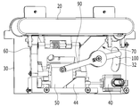
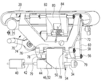
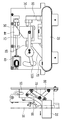
도 2 및 도 3을 참조하면, 본 발명의 실시 예에 따른 차량용 출몰형 아웃사이드 도어 핸들 조립체는, 전기적인 신호를 입력받아 차량의 길이 방향을 따라 전후로 이동 가능한 액츄에이터(40)와, 이 액츄에이터에 의해 차량의 높이 방향을 따라 상하로 이동되는 이동 블록(50)을 더 포함할 수 있다.2 and 3, the car outgoing type outdoor door handle assembly according to an embodiment of the present invention receives an electric signal, and the
액츄에이터(40)는 액츄에이터 로드(42)와, 이 액츄에이터 로드(42)의 선단부에 장착된 플런저(44)를 포함할 수 있고, 플런저(44)는 다각 블록 형상을 하고서 한쪽 모서리를 절단하여 경사진 경사면(46)을 구비할 수 있다.The
이동 블록(50)의 하부에도 상기 경사면(46)에 대응하는 경사면(52)이 한쪽 모서리를 깎은 형태로 구비될 수 있다.An
제1,2핀축(56, 58)이 이동 블록(50)의 양측면으로부터 돌출하도록 설치되고, 제1핀축(56)에는 제1링크(60)의 일단이 끼워져 회전 가능하게 지지될 수 있다.The first and
제2링크(70)는, 차량의 길이 방향을 따라 전후로 이격되게 배치된 2개의 제1링크암(72)과 제2링크암(74), 제1링크암(72)과 제2링크암(74)의 일단들을 연결하는 연결암(76)을 포함하여 대체로 "U"자 형상을 가지며, 연결암(76)에는 2개의 보스(78)가 구비되고, 제2핀축(58)이 2개의 보스(78)를 관통해서 삽입되어, 제2링크(70)도 제2핀축(58)을 매개로 회전 가능하게 지지될 수 있다.The
또한 제1핀축(56)과 제2핀축(58)은 연결부재(79)를 통해 서로 연결될 수 있다.In addition, the
제1링크(60)의 타단과 제2링크(70)의 제1링크암(72) 및 제2링크암(74)의 타단들은 아웃사이드 도어 핸들(20)에 핀축을 통해 회전 가능하게 연결될 수 있다.The other end of the
이에 따라, 제1,2링크(60, 70)들의 이동은 아웃사이드 도어 핸들(20)에 전달되어, 제1,2링크(60, 70)와 아웃사이드 도어 핸들(20)은 연동하게 된다.Accordingly, the movement of the first and
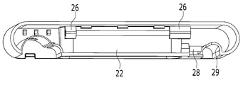
도 4 및 도 5를 참조하면, 아웃사이드 도어 핸들(20)은 핸들 하우징(22)과, 핸들 하우징(22)의 상부면에 형성되어 사용자가 손을 집어 넣어 핸들 하우징(22)을 파지할 수 있는 파지홀(24), 핸들 하우징(22)의 내부에 제1링크암(72)과 제2링크암(74)의 타단들을 회전 가능하게 체결하기 위한 핀축이 결합되는 2개의 보스(26), 제1링크(60)의 타단을 회전 가능하게 체결하기 위한 핀축이 결합되는 보스(28)가 일체로 구비될 수 있다.4 and 5, the
또한, 아웃사이드 도어 핸들(20)이 차량의 폭 방향으로 원활하게 수평 이동하도록 아웃사이드 도어 핸들(20)에는 가이드 돌기(29) 구비될 수 있다. 가이드 돌기(29)는 그 단면이 원호 형상으로 형성될 수 있고, 상기 핸들 아우징(22)에 일체로 형성될 수 있다.In addition, the
도 6 및 도 7을 참조하면, 베이스 플레이트(30)에는 아웃사이드 도어 핸들(20)의 가이드 돌기(29)가 삽입되어, 안내 이동되는 가이드 홈(37)을 구비한 가이드 돌출부(36)가 구비될 수 있다.6 and 7, the
가이드 돌출부(36)는 차량의 폭 방향 외측을 향해 돌출되게 형성될 수 있고, 가이드 홈(37)은 가이드 돌출부(36)의 길이 방향을 따라 채널 형상으로 형성될 수 있다.The
상기 가이드 돌기(29)와 가이드 홈(37) 및 가이드 돌출부(36)는 가이드 기구를 구성할 수 있다.The
이에 따라, 아웃사이드 도어 핸들(20)이 차량의 돌출 외측으로 팝업되거나 다시 도어 아우터 패널(10) 쪽으로 후퇴될 때에, 베이스 플레이트(30)의 가이드 홈(37)에 아웃사이드 도어 핸들(20)의 가이드 돌기(29)가 삽입되어 결합된 상태로 가이드 돌기(29)와 가이드 홈(37)의 상호 작용에 의해, 아웃사이드 도어 핸들(20)이 차량의 폭 방향을 따라 수평하게 안내 이동된다.Accordingly, when the
다시 도 3을 참조하면, 제2링크(70)에는 메인 암(80)의 일단이 핀축(82)을 통해 회전 가능하게 연결되고, 메인 암(80)의 타단은 도어 아우터 패널(10)에 회전 가능하게 장착되며, 메인 암(80)과 제2링크(70) 사이에는 리턴 스프링(84)이 설치되어 있다.Referring back to FIG. 3, one end of the
이에 따라, 제2링크(70)는 메인 암(80)을 통해 도어 아우터 패널(10)에 의해 그 회전 운동이 제한되게 된다.Accordingly, the rotational movement of the
다시 도 2를 참조하면, 이동 블록(50)에는 커넥트 링크(90)의 일단이 체결되고, 커넥트 링크(90)의 타단은 커넥트 로드(100)에 연결되며, 커넥트 로드(100)의 타단은 베이스 플레이트(30)에 형성된 원호 형상의 가이드 홀(32)에 삽입되어, 가이드 홀(32)을 따라 이동할 수 있다.Referring to FIG. 2 again, one end of the
커넥트 로드(100)는 도시되지 않은 도어 래치와 케이블 등을 통해 연결되어, 커넥트 로드(100)가 회동 운동을 하면, 도어 래치가 개방될 수 있다.The
도 8 내지 도 10을 참조하면, 도 8은 아웃사이드 도어 핸들(20)이 도어 아우터 패널(10)의 개구부(12) 내부에 수용되어 있는 상태를 도시한다. 즉 도어가 닫힌 상태를 나타낸다.8 to 10, FIG. 8 shows a state in which the
운전자가 차량에 근접함에 따라 액츄에이터(40)가 제어신호를 인가받아 작동하면, 도 9에 도시된 바와 같이 플런저(44)가 차량의 길이 방향을 따라 전방으로 이동하여, 플런저(44)의 경사면(46)과 이동 블록(50)의 경사면(52)의 상호 작용에 의해 이동 블록(50)이 차량의 높이 방향 상방으로 밀어 올려지게 된다.When the
또한, 이동 블록(50)의 상승으로 이동 블록(50)에 연결된 2개의 제1링크(60)와 제2링크(70)가 함께 상승하게 된다. 제1링크(60)와 제2링크(70)가 상승하면, 제2링크(70)는 메인 암(80)에 핀으로 회동 가능하게 연결됨과 더불어 메인 암(80)은 도어 아우터 패널(10)에 회동 가능하게 연결되어 있기 때문에, 제2링크(70)는 차량의 폭 방향 외측으로 회동 운동을 하게 되고, 제1링크(60)도 동시에 차량의 폭 방향 외측으로 회동 운동을 하여, 제1링크(60)와 제2링크(70)에 연결된 아웃사이드 도어 핸들(20)이 도어 아웃터 패널(10)보다 차량의 폭 방향 외측으로 돌출하게 된다.In addition, as the
이러한 과정에 이동 블록(50)에 연결된 커넥트 링크(90)는 시계 방향으로 회전하게 되지만, 커넥트 링크(90)의 회전 운동은 커넥트 로드(100)에 전달되지 않아서 커넥트 로드(100)는 회전하지 않게 된다.In this process, the
이동 블록(50)이 플런저(44)의 상부면을 타고 올라가서 플런저(44)에 의한 이동 블록(50)의 상승이 완료된 상태에서, 즉 아웃사이드 도어 핸들(20)이 도어 아우터 패널(10)의 외측으로 돌출된 상태에서, 사용자가 아웃사이드 도어 핸들(20)의 파지홀(24)에 손을 집어 넣어 아웃사이드 도어 핸들(20)을 차량의 폭 방향 외측으로 당기면, 도 8에 도시된 바와 같이, 아웃사이드 도어 핸들(20)이 차량의 폭 방향 외측으로 당겨지게 됨과 더불어 제1,2링크(60,70)도 시계 방향으로 회동 운동을 하고, 이동 블록(50)도 더욱 상승하게 된다.When the moving
이러한 과정에 커넥트 링크(90)도 시계 방향으로 더 회전함과 더불어 커넥트 링크(90)의 회전 운동은 커넥트 로드(100)에 전달되어, 커넥트 로드(100)가 베이스 플레이트(30)에 형성된 가이드 홀(32)을 따라 이동하여, 커넥트 로드(100)에 연결된 도어 래치를 해방시켜 줌으로써, 도어가 개방되게 된다.In this process, the
한편, 커넥트 로드(100)의 작동에 따라 도어가 개방된 이후에, 사용자가 아웃사이드 도어 핸들(20)을 해방시키면, 리턴 스프링(84)의 탄성 복원력(84)에 의해 메인 암(80)이 원래의 위치로 회동되고, 메인 암(80)의 회동 운동에 의해 아웃사이드 도어 핸들(20)이 도어 아우터 패널(10)의 개구부(2)내부로 삽입되며, 이동 블록(50)은 초기 위치로 하강하게 된다.On the other hand, after the door is opened according to the operation of the
이러한 이동 블록(50)의 상승 및 하강 과정에, 이동 블록(50)의 원활한 상승 및 정확한 원래의 위치 복귀를 위해, 도 2 및 도 3에 도시된 바와 같이 이동 블록(50)의 하부에는 이동 블록(50)의 내부로 파여진 형태의 가이드 홈(54)이 형성되고, 베이스 플레이트(30)에는 상기 가이드 홈(54)에 삽입되는 가이드 핀(34)이 설치되어 있다.In the process of ascending and descending of the moving
즉, 이동 블록(50)이 상승 및 하강하는 과정에 이동 블록(50)의 가이드 홈(54)은 가이드 핀(34)에 끼워져서, 이동 블록(50)의 운동을 가이드하게 된다.That is, the
도 11를 참조하면, 차량의 스마트 키이나 혹은 액츄에이터(40)가 작동되지 않을 경우에, 일반적인 치량의 키이를 도어를 개방할 수 있도록 키이 실런더(110)가 베이스 플레이트(30)에 장착될 수 있다.Referring to FIG. 11, when the smart key or the
또한, 상기 액츄에이터(40)가 작동 불능이어서 아웃사이드 도어 핸들(20)을 액츄에이터(40)를 매개로 돌출시킬 수 없을 때에, 차량의 이용자가 수동으로 아웃사이드 도어 핸들(20)을 돌출시킬 수 있도록 비상 레버(120)가 더 구비될 수 있다.In addition, when the
비상 레버(120)는 아웃 사이드 도어 핸들(20)에 그 힌지축(122)을 매개로 회전 가능하게 설치되고, 상기 힌지축(122)에는 비상 레버(120)의 작동 후에 비상 레버(120)를 원래의 위치로 복귀시키기 위한 리턴 스프링(124)이 감기는 형태로 설치될 수 있다.The
비상 레버(120)는 대체로 둔각으로 절곡된 레버 바디(126)와, 이 레버 바디(126)의 일단에 형성된 공구홈(128)을 구비할 수 있으며, 상기 레버 바디(126)의 타단에는 상기 힌지축(122)이 관통해서 삽입되어 있다.The
비상 레버(120)는 상기 키이 실린더(110)와 근접되게 배치되어, 비상 레버(120)가 그 힌지축(122)을 중심으로 회동될 때에 상기 키이 실린더(110)가 레버 바디(126)의 지지점 역할을 할 수 있다.
즉, 도 12에 도시된 바와 같이, 차량 이용자가 상기 서술한 이유로 도어를 개방할 수 없을 때에, 두께가 얇은 막대기와 같은 공구(130)를 개구부(12)와 아웃사이드 도어 핸들(20) 사이의 틈새로 집어 넣어서 비상 레버(120)를 밀어 주면, 비상 레버(120)의 일부가 키이 실린더(110)에 접촉하여 키이 실린더(110)를 지지점으로 해서 시계 방향으로 회전하게 되고, 이에 따라 아웃사이드 도어 핸들(20)의 일측이 비상 레버(120)에 의해 차량의 폭 방향 외측으로 밀려서 개구부(12)로부터 약간 돌출하게 됨으로써, 차량 이용자가 돌출된 아웃사이드 도어 핸들(20)를 파지하여 차량의 폭 방향 외측으로 당겨서 도어를 개방할 수 있게 된다.That is, as shown in FIG. 12, when the vehicle user cannot open the door for the reasons described above, a
이상과 같이, 본 발명은 한정된 실시 예와 도면을 통하여 설명되었으나, 본 발명은 이에 한정되는 것은 아니며, 본 발명이 속하는 기술분야에서 통상의 지식을 가진 자에 의해 본 발명의 기술 사상과 아래에 기재된 특허청구범위의 균등범위 내에서 다양한 수정 및 변형이 가능하다. As described above, the present invention has been described through limited embodiments and drawings, but the present invention is not limited thereto, and the technical idea of the present invention and those described below by those skilled in the art to which the present invention pertains Various modifications and variations are possible within the equal scope of the claims.
10: 도어 아우터 패널
12: 개구부
20: 아웃사이드 도어 핸들
30: 베이스 플레이트
40: 액츄에이터
44: 플런저
46: 경사면
50: 이동 블록
52: 경사면
54: 가이드 홈
60: 제1링크
70: 제2링크
80: 메인 암
90: 커넥트 링크
100: 커넥트 로드
110 키이 실린더
120: 비상 레버
130: 공구10: door outer panel
12: opening
20: outside door handle
30: base plate
40: actuator
44: plunger
46: Slope
50: moving block
52: Slope
54: guide groove
60: first link
70: second link
80: main arm
90: Connect link
100: connect rod
110 key cylinder
120: emergency lever
130: tool
Claims (15)
상기 아웃사이드 도어 핸들의 일측에 일단이 연결되고 타단은 차량의 높이 방향을 따라 하방으로 연장된 제1링크;
상기 아웃사이드 도어 핸들의 일측 및 타측에 일단이 연결되고 타단은 차량의 높이 방향을 따라 연장된 제2링크;
일단이 상기 도어 아우터 패널에 회동 가능하게 연결되고 타단은 상기 제2링크에 연결된 메인 암;
상기 제1링크의 타단 및 상기 제2링크의 타단이 연결되고 차량의 높이 방향을 따라 상하로 이동 가능한 이동 블록; 및
상기 아웃사이드 도어 핸들의 차량의 폭 방향을 따른 운동을 가이드하는 가이드 기구;
를 포함하는 차량용 출몰형 아웃사이드 도어 핸들 조립체.
An outer door handle that protrudes outward in the width direction of the vehicle or is housed in an opening formed in the door outer panel than a door outer panel constituting the vehicle door;
A first link having one end connected to one side of the outside door handle and the other end extending downward along a height direction of the vehicle;
A second link having one end connected to one side and the other side of the outside door handle and the other end extending along a height direction of the vehicle;
A main arm having one end rotatably connected to the door outer panel and the other end connected to the second link;
A movable block to which the other end of the first link and the other end of the second link are connected and movable up and down along the height direction of the vehicle; And
A guide mechanism for guiding movement along the width direction of the vehicle of the outside door handle;
Vehicle appearance door handle assembly for a vehicle comprising a.
상기 이동 블록을 차량의 높이 방향을 따른 상방으로 밀어 올리는 액츄에이터를 더 포함하는 것을 특징으로 하는 차량용 출몰형 아웃사이드 도어 핸들 조립체.
According to claim 1,
And an actuator for pushing the moving block upwards along the height direction of the vehicle.
상기 액츄에이터는
액츄에이터 로드 및;
상기 액츄에이터 로드의 선단부에 장착되고 경사면을 구비한 플런저를 포함하고;
상기 이동 블록의 하부에는 상기 경사면에 대응하는 경사면이 구비된 것을 특징으로 하는 차량용 출몰형 아웃사이드 도어 핸들 조립체.
According to claim 1,
The actuator
An actuator rod and;
A plunger mounted on a front end portion of the actuator rod and having an inclined surface;
A lower outboard door handle assembly for a vehicle, characterized in that an inclined surface corresponding to the inclined surface is provided below the moving block.
상기 제2링크는
차량의 길이 방향을 따라 전후로 이격되게 배치되고 상기 아웃사이드 도어 핸들에 일단들이 연결된 제1링크암과 제2링크암; 및
상기 제1링크암 타단과 상기 제2링크암의 타단을 연결하는 연결암;
을 포함하는 것을 특징으로 하는 차량용 출몰형 아웃사이드 도어 핸들 조립체.
According to claim 1,
The second link
A first link arm and a second link arm arranged to be spaced forward and backward along the longitudinal direction of the vehicle and connected to the outside door handles; And
A connecting arm connecting the other end of the first link arm and the other end of the second link arm;
The out-of-vehicle exterior door handle assembly for a vehicle comprising a.
제1핀축이 상기 이동 블록의 양측면으로부터 돌출하도록 설치되고, 상기 제1핀축에는 상기 제1링크의 타단이 끼워져 회전 가능하게 지지된 것을 특징으로 하는 차량용 출몰형 아웃사이드 도어 핸들 조립체.
According to claim 4,
The first pin shaft is installed so as to protrude from both sides of the moving block, the other end of the first link is fitted to the first pin shaft, the vehicle outgoing type outdoor door handle assembly characterized in that it is rotatably supported.
제2핀축이 상기 이동 블록의 양측면으로부터 돌출하도록 설치되고;
상기 연결암에는 보스가 구비되며;
상기 제2핀축은 상기 보스를 관통하여 삽입되어, 상기 제2링크가 상기 제2핀축을 매개로 회전 가능하게 지지된 것을 특징으로 하는 차량용 출몰형 아웃사이드 도어 핸들 조립체.
The method of claim 5,
A second pin shaft is installed to protrude from both sides of the moving block;
The connecting arm is provided with a boss;
The second pin axle is inserted through the boss, and the second link shaft is rotatably supported outside the vehicle door handle assembly, characterized in that supported by the second pin axle.
상기 상기 제1핀축과 상기 제2핀축은 연결부재를 통해 서로 연결된 것을 특징으로 하는 차량용 출몰형 아웃사이드 도어 핸들 조립체.
The method of claim 6,
The first pin shaft and the second pin shaft is connected to each other through a connecting member Vehicle appearance door handle assembly.
상기 아웃사이드 도어 핸들은
핸들 하우징;
상기 핸들 하우징의 상부면에 형성된 파지홀;
상기 핸들 하우징의 내부에 형성되어 상기 제1링크암과 상기 제2링크암의 일단들을 회전 가능하게 체결하기 위한 핀축이 결합되는 보스; 및
상기 제1링크의 일단을 회전 가능하게 체결하기 위한 핀축이 결합되는 보스;
를 구비한 것을 특징으로 하는 차량용 출몰형 아웃사이드 도어 핸들 조립체.
According to claim 1,
The outside door handle
Handle housing;
A gripping hole formed on an upper surface of the handle housing;
A boss formed inside the handle housing and having a pin shaft for rotatably fastening ends of the first link arm and the second link arm; And
A boss to which a pin shaft for rotatably fastening one end of the first link is coupled;
It characterized in that it has a vehicle exterior door handle assembly.
상기 제2링크에는 상기 메인 암의 일단이 핀축을 통해 회전 가능하게 연결되고;
상기 메인 암의 타단은 상기 도어 아우터 패널에 회전 가능하게 장착된 것을 특징으로 하는 차량용 출몰형 아웃사이드 도어 핸들 조립체.
According to claim 1,
One end of the main arm is rotatably connected to the second link through a pin shaft;
The other end of the main arm is rotatably mounted outside the door handle assembly for a vehicle, characterized in that mounted on the door outer panel.
상기 메인 암과 상기 제2링크 사이에는 리턴 스프링이 설치된 것을 특징으로 하는 차량용 출몰형 아웃사이드 도어 핸들 조립체.
According to claim 1,
A return door handle assembly for a vehicle, characterized in that a return spring is installed between the main arm and the second link.
상기 이동 블록의 하부에는 가이드 홈이 형성되고;
상기 가이드 홈에 삽입되어 상기 이동 블록을 가이드하는 가이드 핀이 더 구비된 것을 특징으로 하는 차량용 출몰형 아웃사이드 도어 핸들 조립체.According to claim 1,
A guide groove is formed under the moving block;
Vehicle guide door assembly characterized in that it is further provided with a guide pin that is inserted into the guide groove to guide the moving block.
아웃사이드 도어 핸들의 일측에는 비상 레버의 일측이 회전 가능하게 설치되고;
상기 비상 레버의 타측은 지지점을 중심으로 회전 가능하게 설치된 것을 특징으로 하는 차량용 출몰형 아웃사이드 도어 핸들 조립체.According to claim 1,
One side of the emergency lever is rotatably installed on one side of the outside door handle;
The other side of the emergency lever is a rotatable outside door handle assembly for a vehicle, characterized in that rotatably installed around a support point.
상기 차량의 도어를 키이 조작으로 개폐할 수 있는 키이 실린더가 더 구비되고;
상기 키이 실린더는 상기 비상 레버의 상기 지지점을 형성하는 것을 특징으로 하는 차량용 출몰형 아웃사이드 도어 핸들 조립체.
According to claim 1,
A key cylinder that can open and close the door of the vehicle by a key operation is further provided;
The key cylinder forms the support point of the emergency lever.
상기 가이드 기구는,
상기 핸들 하우징에 구비된 가이드 돌기; 및
상기 도어 아우터 패널에 고정되게 장착된 베이스 플레이트에 구비되어, 상기 가이드 돌기가 삽입되어 안내 이동되는 가이드 홈을 구비한 가이드 돌출부;
를 포함하는 특징으로 하는 차량용 출몰형 아웃사이드 도어 핸들 조립체.The method of claim 8,
The guide mechanism,
A guide projection provided on the handle housing; And
A guide protrusion provided on a base plate fixedly mounted to the door outer panel and having a guide groove through which the guide projection is inserted and guided;
A door-mounted exterior door handle assembly for a vehicle, comprising:
상기 가이드 돌출부는 상기 베이스 플레이트에 차량의 폭 방향을 따른 내측내측부터 외측으로 돌출하도록 구비된 것을 특징으로 하는 차량용 출몰형 아웃사이드 도어 핸들 조립체.The method of claim 14,
The guide protrusion is provided on the base plate so as to protrude from the inside to the outside along the width direction of the vehicle The outboard door handle assembly for a vehicle.
Priority Applications (4)
| Application Number | Priority Date | Filing Date | Title |
|---|---|---|---|
| KR1020180120849A KR20200041004A (en) | 2018-10-11 | 2018-10-11 | Retractable outside door handle assembly for vehicle |
| US16/193,964 US10961753B2 (en) | 2018-10-11 | 2018-11-16 | Retractable outside door handle assembly for vehicle |
| DE102018130161.8A DE102018130161A1 (en) | 2018-10-11 | 2018-11-28 | Retractable outer door handle assembly for a vehicle |
| CN201811496743.7A CN111042673B (en) | 2018-10-11 | 2018-12-07 | Retractable outside door handle assembly for vehicle |
Applications Claiming Priority (1)
| Application Number | Priority Date | Filing Date | Title |
|---|---|---|---|
| KR1020180120849A KR20200041004A (en) | 2018-10-11 | 2018-10-11 | Retractable outside door handle assembly for vehicle |
Publications (1)
| Publication Number | Publication Date |
|---|---|
| KR20200041004A true KR20200041004A (en) | 2020-04-21 |
Family
ID=69954270
Family Applications (1)
| Application Number | Title | Priority Date | Filing Date |
|---|---|---|---|
| KR1020180120849A KR20200041004A (en) | 2018-10-11 | 2018-10-11 | Retractable outside door handle assembly for vehicle |
Country Status (4)
| Country | Link |
|---|---|
| US (1) | US10961753B2 (en) |
| KR (1) | KR20200041004A (en) |
| CN (1) | CN111042673B (en) |
| DE (1) | DE102018130161A1 (en) |
Families Citing this family (1)
| Publication number | Priority date | Publication date | Assignee | Title |
|---|---|---|---|---|
| KR102144784B1 (en) * | 2019-01-22 | 2020-08-18 | 주식회사 우보테크 | Flush Handle For Vehicle Door |
Family Cites Families (18)
| Publication number | Priority date | Publication date | Assignee | Title |
|---|---|---|---|---|
| DE19833168B4 (en) | 1998-07-23 | 2007-06-06 | Ewald Witte Gmbh & Co Kg | Handle fitting for a motor vehicle sliding door |
| US8943752B2 (en) * | 2007-01-05 | 2015-02-03 | Ford Global Technologies, Llc | Door handle system for an automotive vehicle |
| US8282142B2 (en) * | 2008-11-25 | 2012-10-09 | GM Global Technology Operations LLC | Latch release system for a door assembly of a vehicle |
| DE102009053553A1 (en) | 2009-11-18 | 2011-05-19 | Huf Hülsbeck & Fürst Gmbh & Co. Kg | Safety handle |
| GB2477085B (en) * | 2010-01-15 | 2014-08-20 | Jaguar Land Rover Ltd | Retractable handle for a door or the like |
| US9151089B2 (en) * | 2011-09-26 | 2015-10-06 | Tesla Motors, Inc. | Controller apparatus and sensors for a vehicle door handle |
| US9103143B2 (en) * | 2011-09-26 | 2015-08-11 | Tesla Motors, Inc. | Door handle apparatus for vehicles |
| US8443553B1 (en) | 2011-11-23 | 2013-05-21 | GM Global Technology Operations LLC | Closure assembly with moveable cover and closeout for a retractable handle |
| US8690204B2 (en) * | 2011-11-23 | 2014-04-08 | GM Global Technology Operations LLC | Flush door handle assembly with normal deployment |
| US8919047B2 (en) * | 2012-08-15 | 2014-12-30 | GM Global Technology Operations LLC | Normally deploying flush door handle |
| DE102013017664A1 (en) * | 2013-09-27 | 2015-04-02 | Huf Hülsbeck & Fürst Gmbh & Co. Kg | An automobile door handle |
| DE102013112706A1 (en) | 2013-11-18 | 2015-05-21 | Illinois Tool Works Inc. | System comprising a door handle and an actuating device for the door handle |
| US9249608B2 (en) * | 2014-05-05 | 2016-02-02 | GM Global Technology Operations LLC | Flush door handle with shape memory alloy drive and heated handle to body seal |
| KR101637820B1 (en) | 2015-03-24 | 2016-07-07 | 현대자동차주식회사 | Retractable handle system for vehicle |
| CN105507699B (en) | 2016-01-19 | 2017-10-03 | 无锡忻润汽车安全系统有限公司 | Automobile auto-extending door handle |
| DE102016112689A1 (en) | 2016-07-11 | 2018-01-11 | Huf Hülsbeck & Fürst Gmbh & Co. Kg | Handle device with a flush handle |
| KR101875658B1 (en) | 2016-08-24 | 2018-07-06 | 현대자동차 주식회사 | Retractable outside door handle assembly for vehicle |
| KR102621229B1 (en) * | 2018-08-31 | 2024-01-04 | 현대자동차 주식회사 | Retractable outside door handle assembly for vehicle |
-
2018
- 2018-10-11 KR KR1020180120849A patent/KR20200041004A/en not_active Application Discontinuation
- 2018-11-16 US US16/193,964 patent/US10961753B2/en active Active
- 2018-11-28 DE DE102018130161.8A patent/DE102018130161A1/en active Pending
- 2018-12-07 CN CN201811496743.7A patent/CN111042673B/en active Active
Also Published As
| Publication number | Publication date |
|---|---|
| CN111042673B (en) | 2021-11-16 |
| CN111042673A (en) | 2020-04-21 |
| US20200115935A1 (en) | 2020-04-16 |
| DE102018130161A1 (en) | 2020-04-16 |
| US10961753B2 (en) | 2021-03-30 |
Similar Documents
| Publication | Publication Date | Title |
|---|---|---|
| KR102621229B1 (en) | Retractable outside door handle assembly for vehicle | |
| KR101875658B1 (en) | Retractable outside door handle assembly for vehicle | |
| CN110607961B (en) | Retractable outside door handle assembly for vehicle | |
| CN111236770B (en) | Door handle of vehicle | |
| US4588219A (en) | Door handle unit suitable for use in an automobile | |
| EP2619389B1 (en) | Vehicle door handle device | |
| CN110273601A (en) | The device for opening with linear actuators for motor vehicles | |
| JPS6252885B2 (en) | ||
| KR101946915B1 (en) | Assembly of Flush Door Dandle for Vehicle | |
| JP2009506939A (en) | Vehicle roof having at least two cover elements | |
| KR20200041004A (en) | Retractable outside door handle assembly for vehicle | |
| US20220290472A1 (en) | Opening and closing device for glove boxes | |
| KR102663985B1 (en) | Retractable outside door handle assembly for vehicle | |
| KR20200025511A (en) | Inertia Linkage and Retractable outside door handle assembly for vehicle using the same | |
| CN115506663B (en) | Hidden car door handle of flat-open and vehicle | |
| KR20020040346A (en) | a tail gate latch for vehicles | |
| KR0140681Y1 (en) | Hood locking latch installation of a motor vehicle | |
| KR100507306B1 (en) | Long-Slide Locking Structure of Seat for Automobile | |
| KR20200055462A (en) | Retractable outside door handle assembly for vehicle | |
| CN116950509A (en) | Door handle assembly for vehicle | |
| JPH063120Y2 (en) | Vehicle door lock device | |
| KR20160093286A (en) | Hood Safety Catch System | |
| JP2000185551A (en) | Vehicle door grip |
Legal Events
| Date | Code | Title | Description |
|---|---|---|---|
| A201 | Request for examination | ||
| E902 | Notification of reason for refusal |