KR20200040190A - Battery system for vehicle and method for detecting overheat situation of battery system - Google Patents
Battery system for vehicle and method for detecting overheat situation of battery system Download PDFInfo
- Publication number
- KR20200040190A KR20200040190A KR1020190114258A KR20190114258A KR20200040190A KR 20200040190 A KR20200040190 A KR 20200040190A KR 1020190114258 A KR1020190114258 A KR 1020190114258A KR 20190114258 A KR20190114258 A KR 20190114258A KR 20200040190 A KR20200040190 A KR 20200040190A
- Authority
- KR
- South Korea
- Prior art keywords
- battery
- gas sensor
- gas species
- coating
- gas
- Prior art date
Links
Images
Classifications
-
- H—ELECTRICITY
- H01—ELECTRIC ELEMENTS
- H01M—PROCESSES OR MEANS, e.g. BATTERIES, FOR THE DIRECT CONVERSION OF CHEMICAL ENERGY INTO ELECTRICAL ENERGY
- H01M50/00—Constructional details or processes of manufacture of the non-active parts of electrochemical cells other than fuel cells, e.g. hybrid cells
- H01M50/50—Current conducting connections for cells or batteries
- H01M50/569—Constructional details of current conducting connections for detecting conditions inside cells or batteries, e.g. details of voltage sensing terminals
-
- H—ELECTRICITY
- H01—ELECTRIC ELEMENTS
- H01M—PROCESSES OR MEANS, e.g. BATTERIES, FOR THE DIRECT CONVERSION OF CHEMICAL ENERGY INTO ELECTRICAL ENERGY
- H01M10/00—Secondary cells; Manufacture thereof
- H01M10/42—Methods or arrangements for servicing or maintenance of secondary cells or secondary half-cells
- H01M10/48—Accumulators combined with arrangements for measuring, testing or indicating the condition of cells, e.g. the level or density of the electrolyte
-
- G—PHYSICS
- G01—MEASURING; TESTING
- G01N—INVESTIGATING OR ANALYSING MATERIALS BY DETERMINING THEIR CHEMICAL OR PHYSICAL PROPERTIES
- G01N33/00—Investigating or analysing materials by specific methods not covered by groups G01N1/00 - G01N31/00
- G01N33/0004—Gaseous mixtures, e.g. polluted air
- G01N33/0009—General constructional details of gas analysers, e.g. portable test equipment
- G01N33/0062—General constructional details of gas analysers, e.g. portable test equipment concerning the measuring method, e.g. intermittent, or the display, e.g. digital
- G01N33/0063—General constructional details of gas analysers, e.g. portable test equipment concerning the measuring method, e.g. intermittent, or the display, e.g. digital using a threshold to release an alarm or displaying means
-
- G—PHYSICS
- G01—MEASURING; TESTING
- G01R—MEASURING ELECTRIC VARIABLES; MEASURING MAGNETIC VARIABLES
- G01R31/00—Arrangements for testing electric properties; Arrangements for locating electric faults; Arrangements for electrical testing characterised by what is being tested not provided for elsewhere
- G01R31/36—Arrangements for testing, measuring or monitoring the electrical condition of accumulators or electric batteries, e.g. capacity or state of charge [SoC]
- G01R31/392—Determining battery ageing or deterioration, e.g. state of health
-
- H—ELECTRICITY
- H01—ELECTRIC ELEMENTS
- H01M—PROCESSES OR MEANS, e.g. BATTERIES, FOR THE DIRECT CONVERSION OF CHEMICAL ENERGY INTO ELECTRICAL ENERGY
- H01M10/00—Secondary cells; Manufacture thereof
- H01M10/42—Methods or arrangements for servicing or maintenance of secondary cells or secondary half-cells
- H01M10/4207—Methods or arrangements for servicing or maintenance of secondary cells or secondary half-cells for several batteries or cells simultaneously or sequentially
-
- H—ELECTRICITY
- H01—ELECTRIC ELEMENTS
- H01M—PROCESSES OR MEANS, e.g. BATTERIES, FOR THE DIRECT CONVERSION OF CHEMICAL ENERGY INTO ELECTRICAL ENERGY
- H01M10/00—Secondary cells; Manufacture thereof
- H01M10/42—Methods or arrangements for servicing or maintenance of secondary cells or secondary half-cells
- H01M10/425—Structural combination with electronic components, e.g. electronic circuits integrated to the outside of the casing
-
- H—ELECTRICITY
- H01—ELECTRIC ELEMENTS
- H01M—PROCESSES OR MEANS, e.g. BATTERIES, FOR THE DIRECT CONVERSION OF CHEMICAL ENERGY INTO ELECTRICAL ENERGY
- H01M10/00—Secondary cells; Manufacture thereof
- H01M10/42—Methods or arrangements for servicing or maintenance of secondary cells or secondary half-cells
- H01M10/48—Accumulators combined with arrangements for measuring, testing or indicating the condition of cells, e.g. the level or density of the electrolyte
- H01M10/486—Accumulators combined with arrangements for measuring, testing or indicating the condition of cells, e.g. the level or density of the electrolyte for measuring temperature
-
- H01M2/0262—
-
- H—ELECTRICITY
- H01—ELECTRIC ELEMENTS
- H01M—PROCESSES OR MEANS, e.g. BATTERIES, FOR THE DIRECT CONVERSION OF CHEMICAL ENERGY INTO ELECTRICAL ENERGY
- H01M50/00—Constructional details or processes of manufacture of the non-active parts of electrochemical cells other than fuel cells, e.g. hybrid cells
- H01M50/10—Primary casings, jackets or wrappings of a single cell or a single battery
- H01M50/116—Primary casings, jackets or wrappings of a single cell or a single battery characterised by the material
- H01M50/117—Inorganic material
- H01M50/119—Metals
-
- H—ELECTRICITY
- H01—ELECTRIC ELEMENTS
- H01M—PROCESSES OR MEANS, e.g. BATTERIES, FOR THE DIRECT CONVERSION OF CHEMICAL ENERGY INTO ELECTRICAL ENERGY
- H01M50/00—Constructional details or processes of manufacture of the non-active parts of electrochemical cells other than fuel cells, e.g. hybrid cells
- H01M50/10—Primary casings, jackets or wrappings of a single cell or a single battery
- H01M50/116—Primary casings, jackets or wrappings of a single cell or a single battery characterised by the material
- H01M50/124—Primary casings, jackets or wrappings of a single cell or a single battery characterised by the material having a layered structure
-
- H—ELECTRICITY
- H01—ELECTRIC ELEMENTS
- H01M—PROCESSES OR MEANS, e.g. BATTERIES, FOR THE DIRECT CONVERSION OF CHEMICAL ENERGY INTO ELECTRICAL ENERGY
- H01M10/00—Secondary cells; Manufacture thereof
- H01M10/60—Heating or cooling; Temperature control
- H01M10/65—Means for temperature control structurally associated with the cells
- H01M10/656—Means for temperature control structurally associated with the cells characterised by the type of heat-exchange fluid
- H01M10/6561—Gases
- H01M10/6563—Gases with forced flow, e.g. by blowers
-
- H—ELECTRICITY
- H01—ELECTRIC ELEMENTS
- H01M—PROCESSES OR MEANS, e.g. BATTERIES, FOR THE DIRECT CONVERSION OF CHEMICAL ENERGY INTO ELECTRICAL ENERGY
- H01M10/00—Secondary cells; Manufacture thereof
- H01M10/42—Methods or arrangements for servicing or maintenance of secondary cells or secondary half-cells
- H01M10/425—Structural combination with electronic components, e.g. electronic circuits integrated to the outside of the casing
- H01M2010/4271—Battery management systems including electronic circuits, e.g. control of current or voltage to keep battery in healthy state, cell balancing
-
- H—ELECTRICITY
- H01—ELECTRIC ELEMENTS
- H01M—PROCESSES OR MEANS, e.g. BATTERIES, FOR THE DIRECT CONVERSION OF CHEMICAL ENERGY INTO ELECTRICAL ENERGY
- H01M2200/00—Safety devices for primary or secondary batteries
- H01M2200/10—Temperature sensitive devices
-
- H—ELECTRICITY
- H01—ELECTRIC ELEMENTS
- H01M—PROCESSES OR MEANS, e.g. BATTERIES, FOR THE DIRECT CONVERSION OF CHEMICAL ENERGY INTO ELECTRICAL ENERGY
- H01M2220/00—Batteries for particular applications
- H01M2220/20—Batteries in motive systems, e.g. vehicle, ship, plane
-
- H—ELECTRICITY
- H01—ELECTRIC ELEMENTS
- H01M—PROCESSES OR MEANS, e.g. BATTERIES, FOR THE DIRECT CONVERSION OF CHEMICAL ENERGY INTO ELECTRICAL ENERGY
- H01M50/00—Constructional details or processes of manufacture of the non-active parts of electrochemical cells other than fuel cells, e.g. hybrid cells
- H01M50/10—Primary casings, jackets or wrappings of a single cell or a single battery
- H01M50/131—Primary casings, jackets or wrappings of a single cell or a single battery characterised by physical properties, e.g. gas-permeability or size
-
- Y—GENERAL TAGGING OF NEW TECHNOLOGICAL DEVELOPMENTS; GENERAL TAGGING OF CROSS-SECTIONAL TECHNOLOGIES SPANNING OVER SEVERAL SECTIONS OF THE IPC; TECHNICAL SUBJECTS COVERED BY FORMER USPC CROSS-REFERENCE ART COLLECTIONS [XRACs] AND DIGESTS
- Y02—TECHNOLOGIES OR APPLICATIONS FOR MITIGATION OR ADAPTATION AGAINST CLIMATE CHANGE
- Y02E—REDUCTION OF GREENHOUSE GAS [GHG] EMISSIONS, RELATED TO ENERGY GENERATION, TRANSMISSION OR DISTRIBUTION
- Y02E60/00—Enabling technologies; Technologies with a potential or indirect contribution to GHG emissions mitigation
- Y02E60/10—Energy storage using batteries
-
- Y—GENERAL TAGGING OF NEW TECHNOLOGICAL DEVELOPMENTS; GENERAL TAGGING OF CROSS-SECTIONAL TECHNOLOGIES SPANNING OVER SEVERAL SECTIONS OF THE IPC; TECHNICAL SUBJECTS COVERED BY FORMER USPC CROSS-REFERENCE ART COLLECTIONS [XRACs] AND DIGESTS
- Y02—TECHNOLOGIES OR APPLICATIONS FOR MITIGATION OR ADAPTATION AGAINST CLIMATE CHANGE
- Y02T—CLIMATE CHANGE MITIGATION TECHNOLOGIES RELATED TO TRANSPORTATION
- Y02T10/00—Road transport of goods or passengers
- Y02T10/60—Other road transportation technologies with climate change mitigation effect
- Y02T10/70—Energy storage systems for electromobility, e.g. batteries
Abstract
Description
본 발명은 차량용 전지 시스템 및 전지 시스템의 과열 상황 검출 방법에 관한 것이다. The present invention relates to a vehicle battery system and a method for detecting an overheat condition of the battery system.
최근 이동을 위한 에너지원으로 전기 에너지를 사용하는 전기 차량의 개발이 활발하다. 이러한 전기 차량은 충전식 전지에 저장된 에너지를 사용하는 전기 모터에 의해 구동된다. 전기 차량은 전적으로 전지들에 의해 구동되거나, 전지들에 의해 구동되는 전기 모터와 연소 엔진(예를 들어, 가솔린 발전기)에 의해 구동되는 하이브리드 차량의 형태일 수 있다. 2. Description of the Related Art Recently, electric vehicles using electric energy as an energy source for movement have been actively developed. These electric vehicles are driven by electric motors that use energy stored in rechargeable batteries. The electric vehicle may be entirely powered by batteries, or may be in the form of a hybrid vehicle driven by electric motors and combustion engines (eg, gasoline generators) driven by the batteries.
일반적으로, 전기 차량용 전지(electric vehicle battery, EVB) 또는 견인 전지(traction battery)는 전지 전기 차량(battery electric vehicle, BEV)의 추진력을 공급하는데 사용되는 전지이다. 전기 차량용 전지는, 연속되는 기간 동안 전력을 공급하도록 설계되었으므로, 시동(starting), 조명(lighting), 및 점화(ignition)용 전지와 다르다. In general, an electric vehicle battery (EVB) or a traction battery is a battery used to supply propulsion power of a battery electric vehicle (BEV). Batteries for electric vehicles are different from those for starting, lighting, and ignition, since they are designed to supply power for a continuous period.
이차전지(rechargeable or secondary battery)는 충전과 방전을 반복적으로할 수 있다는 점에서, 화학 에너지로부터 전기 에너지로 비가역적 변환만을 하는 일차 전지(primary battery)와 다르다. 저용량의 이차전지는 셀룰러폰, 노트북 컴퓨터 및 캠코더와 같은 소형 전자 장치용 전원으로서 사용되는 반면, 고용량의 이차전지는 전기 차량 등을 위한 전원으로 사용된다.Secondary batteries (rechargeable or secondary batteries) are different from primary batteries that perform irreversible conversion from chemical energy to electrical energy in that they can repeatedly charge and discharge. Low-capacity secondary batteries are used as power sources for small electronic devices such as cellular phones, notebook computers, and camcorders, while high-capacity secondary batteries are used as power sources for electric vehicles and the like.
일반적으로, 이차전지들은 양극, 음극, 및 양극과 음극 사이에 개재된 세퍼레이터를 포함하는 전극 조립체, 전극 조립체를 수용하는 케이스 및 전극 조립체에 전기적으로 연결되는 전극 단자들을 포함한다. 양극, 음극 및 전해액의 화학적 반응을 통해 이차전지의 충전 및 방전이 가능하도록 하기 위해, 이차전지의 케이스 내부로 전해액이 주입된다. 케이스의 형상은 예를 들어, 원통형, 직사각형 등으로 전지의 용도에 따라서 달라진다. 최근 개발 중인 전기 차량들에는 랩탑(laptop) 및 가전 제품에 널리 사용되는 것으로 알려진 리튬 이온 전지가 주로 적용된다.In general, secondary batteries include an electrode assembly including an anode, a cathode, and a separator interposed between the anode and the cathode, a case accommodating the electrode assembly, and electrode terminals electrically connected to the electrode assembly. In order to enable charging and discharging of the secondary battery through the chemical reaction of the positive electrode, the negative electrode and the electrolyte, the electrolyte is injected into the case of the secondary battery. The shape of the case is, for example, cylindrical, rectangular, etc., depending on the application of the battery. Background Art Lithium ion batteries, which are known to be widely used in laptops and home appliances, are mainly applied to electric vehicles currently being developed.
이차전지들은 예를 들어, 전기 차량의 모터 구동을 위한 경우와 같이 높은 에너지 밀도를 제공하기 위해, 직렬 및/또는 병렬로 결합된 복수의 단위 전지 셀로 형성되는 전지 모듈 형태로 사용될 수 있다. 즉, 전지 모듈은 고출력의 충전식 전지를 구현하기 위해, 필요한 전력량에 따라 복수의 단위 전지 셀의 전극 단자들을 연결하여 형성된다.The secondary batteries may be used in the form of a battery module formed of a plurality of unit battery cells coupled in series and / or in parallel to provide a high energy density, for example, for driving a motor of an electric vehicle. That is, the battery module is formed by connecting electrode terminals of a plurality of unit battery cells according to the amount of power required to realize a high-power rechargeable battery.
전지 시스템(또는 전지 팩)은 전지 모듈들을 포함하며, 이들은 원하는 전압, 용량 또는 전력 밀도를 제공하기 위해 직렬, 병렬 또는 두 가지 혼합 방식으로 구성될 수 있다. 전지 시스템의 구성요소에는 개별 전지 모듈들과, 그들 사이에서 전기 전도성을 제공하는 상호 접속을 포함한다. A battery system (or battery pack) includes battery modules, which can be configured in series, parallel, or a combination of both to provide the desired voltage, capacity, or power density. Components of the battery system include individual battery modules and interconnects that provide electrical conductivity between them.
전지의 전력 출력 및 충전에 대한 고정(static) 제어만으로는 전지 시스템에 연결된 다양한 전기 소비자들의 동적 전력 수요를 충족시키기에 충분하지 않다. 따라서, 전지 시스템과 전기 소비자의 제어기 사이에는 지속적 또는 간헐적인 정보 교환이 요구된다. 전지 시스템과 전기 소비자의 제어기 사이에 교환되는 정보는, 전기 소비자의 실제/예측된 전력 수요나 잉여 전력뿐만 아니라, 전지 시스템의 충전 상태(State of Charge, SoC), 잠재적인 전기 성능, 충전 능력 및 내부 저항을 포함한다. Static control of the battery's power output and charging is not enough to meet the dynamic power demands of various electrical consumers connected to the battery system. Therefore, continuous or intermittent information exchange is required between the battery system and the controller of the electric consumer. The information exchanged between the battery system and the controller of the electric consumer includes not only the actual / predicted power demand or surplus power of the electric consumer, but also the state of charge (SoC) of the battery system, potential electrical performance, charging capability, and Includes internal resistance.
전지 시스템들은 통상적으로 전술한 정보를 처리하기 위한 전지 관리 시스템(battery management system, BMS) 및/또는 전지 관리 유닛(battery management unit, BMU)를 포함한다. Battery systems typically include a battery management system (BMS) and / or a battery management unit (BMU) for processing the aforementioned information.
BMS/BMU는 적절한 통신 버스, 예를 들어, SPI 또는 CAN 인터페이스를 통해 다양한 전기 소비자의 제어기와 통신할 수 있다. BMS/BMU는 각 전지 서브 모듈, 특히 각 전지 서브 모듈의 셀 감시 회로(Cell Supervision Circuit, CSC)와 통신할 수 있다. CSC는 각 전지 서브 모듈의 전지 셀들을 상호 연결할 수 있는 적어도 하나의 셀 연결 및 감지 유닛(Cell Connection and Sensing Unit, CCU)과 연결될 수 있다. The BMS / BMU can communicate with the controllers of various electrical consumers through an appropriate communication bus, for example an SPI or CAN interface. The BMS / BMU may communicate with each battery sub-module, particularly the cell supervision circuit (CSC) of each battery sub-module. The CSC may be connected to at least one cell connection and sensing unit (CCU) capable of interconnecting battery cells of each battery submodule.
BMS/BMU는 전지가 자신의 안전 동작 영역(safe operating area, SOA)을 벗어나 동작하는 것으로부터의 보호, 전지 상태 모니터링, 보조 데이터의 계산, 데이터 보고, 전지 환경 제어, 인증, 및/또는 전지 밸런싱 등을 통해, 전지 시스템을 관리하도록 제공된다. BMS / BMU protects the battery from operating out of its safe operating area (SOA), monitors battery health, calculates auxiliary data, reports data, controls the battery environment, authenticates, and / or balances the battery And the like, and are provided to manage the battery system.
전지 시스템의 열 제어를 제공하기 위해서는, 이차전지로부터 발생된 열을 효율적으로 배출(emitting), 방출(discharging) 및/또는 방산(dissipating)함으로써 전지 모듈을 안전하게 사용하기 위한 열 관리 시스템이 필요하다. 열 배출/방출/방산이 충분히 수행되지 않으면, 각 전지 셀 사이에 온도 편차가 발생하여 전지 모듈이 원하는 양의 전력을 생성할 수 없게 된다. 또한, 내부의 온도 상승은 그 내부에서 비정상적인 반응을 일으킬 수 있으며, 이로 인해 이차전지의 충전 및 방전 성능이 저하되고 이차전지의 수명이 단축된다. 따라서, 셀로부터 열을 효과적으로 배출/방출/방산하기 위한 셀 냉각이 필요하다.In order to provide thermal control of a battery system, a thermal management system for safely using the battery module by efficiently discharging, discharging and / or dissipating heat generated from the secondary battery is required. If heat dissipation / dissipation / dissipation is not sufficiently performed, a temperature deviation occurs between each battery cell, and the battery module cannot generate a desired amount of power. In addition, an internal temperature rise may cause an abnormal reaction therein, thereby reducing the charging and discharging performance of the secondary battery and shortening the life of the secondary battery. Therefore, there is a need for cell cooling to effectively discharge / dissipate / dissipate heat from the cell.
독성 가스, 연기 등과 같이 전지 시스템의 유해한 배출물로부터의 차량 승객 보호를 포함하는 안전성 요구사항(safety requirement)은, 일반적으로 전지 모듈과 BMS/BMU를 감싸는 기밀 하우징에 의해 이러한 배출물의 배출을 제한하는 방식으로 이루어진다. Safety requirements, including the protection of vehicle passengers from harmful emissions of the battery system, such as toxic gases, smoke, etc., are generally limited to the emission limits of these emissions by means of airtight housings surrounding the battery module and BMS / BMU. Is made of
그러나, 이러한 기밀 하우징은 승객을 유해한 연기로부터 보호할 수 있지만, 전지 시스템의 심각한 손상(예를 들어, 전지 시스템의 폭발)을 야기할 수 있는 전지 시스템의 임계상태의 검출을 복잡하게 한다. 이러한 전지 시스템의 심각한 손상은, 과열 상황에 의해 발생할 수 있다. 지금까지, BMS/BMU는 예를 들어, 전압, 전류 및 온도와 관련해 획득된 측정치들에만 기초하여 과열 상황을 검출할 수 있었다. 그러나, 설치 공간의 제한과 비용 절감의 이유로 전지 시스템에서 발생하는 모든 과열 상황들이 온도 센서들에 의해 적정한 시간 내에 감지되기 어려운 문제가 있다. 예를 들어, 잘못 조여진 버스 바들은, 전지 셀들 또는 릴레이들의 파괴로 이어지거나 전지 셀들 또는 다른 내부 요소들을 과열시킬 수 있는, 높은 전력 소실 및 열을 발생시키나, 설치 공간의 제한과 비용 절감의 이유로 인해, 모든 전지 셀과 버스 바들 간의 상호 접속이 온도 센서들에 의해 감독될 수 있는 것은 아니다. However, such an airtight housing complicates the detection of the critical condition of the battery system, which can protect the passenger from harmful smoke, but can cause serious damage to the battery system (eg, explosion of the battery system). Serious damage to such a battery system can be caused by an overheating situation. So far, the BMS / BMU has been able to detect an overheating situation based only on measurements obtained with respect to voltage, current and temperature, for example. However, there is a problem that it is difficult to detect all overheating conditions occurring in the battery system within a reasonable time by temperature sensors due to limitations in installation space and cost reduction. For example, incorrectly tightened bus bars generate high power dissipation and heat, which can lead to the destruction of battery cells or relays or overheat the battery cells or other internal elements, but due to limitations in installation space and cost savings However, not all battery cells and interconnections between bus bars can be supervised by temperature sensors.
본 발명의 실시 예를 통해 해결하고자 하는 과제는, 차량용 전지 시스템의 과열 상황 검출 성능을 향상시킬 수 있는 전지 시스템 및 전지 시스템의 과열 상황 검출 방법을 제공하는 것이다. An object to be solved through an embodiment of the present invention is to provide a battery system and a method for detecting an overheating condition of the battery system, which can improve the performance of detecting an overheating condition of the vehicle battery system.
상기 과제를 해결하기 위한 본 발명의 일 양태는 차량용 전지 시스템에 관한 것이다. 상기 차량용 전지 시스템은, 각각이 복수의 이차전지 셀들을 포함하는 적어도 하나의 전지 모듈, 적어도 하나의 가스 센서, 및 상기 적어도 하나의 전지 모듈 및 상기 적어도 하나의 가스 센서를 수용하기 위한 하우징을 포함한다.One aspect of the present invention for solving the above problems relates to a vehicle battery system. The vehicular battery system includes at least one battery module, at least one gas sensor, each including a plurality of secondary battery cells, and a housing for accommodating the at least one battery module and the at least one gas sensor. .
상기 전지 모듈들의 외부 표면의 적어도 일부 및/또는 상기 하우징의 내부 표면의 적어도 일부는, 온도가 소정 온도를 초과하면 적어도 하나의 가스 종(gaseous species)을 방출하도록 구성된 코팅에 의해 커버된다. At least a portion of the outer surface of the battery modules and / or at least a portion of the inner surface of the housing are covered by a coating configured to release at least one gaseous species if the temperature exceeds a predetermined temperature.
상기 가스 센서는 상기 적어도 하나의 가스 종을 검출하도록 구성된다.The gas sensor is configured to detect the at least one gas species.
상기 코팅은 감온(thermally sensitive) 코팅일 수 있다. 상기 코팅의 온도가 소정의 임계값에 도달하면, 상기 코팅은 상기 적어도 하나의 가스 종을 방출하기 시작한다. 상기 적어도 하나의 가스 종은 상기 전지 시스템의 내부 공간에 배치된 상기 가스 센서에 의해 검출된다. The coating may be a thermally sensitive coating. When the temperature of the coating reaches a predetermined threshold, the coating begins to release the at least one gas species. The at least one gas species is detected by the gas sensor disposed in the interior space of the battery system.
상기 전지 시스템은, 전지 관리 시스템(battery management system, BMS)을 더 포함할 수 있다. 상기 BMS는 상기 가스 센서와 통신할 수 있다. 상기 BMS는 필요한 경우, 안전 및 비상조치를 시작할 수도 있다. The battery system may further include a battery management system (BMS). The BMS can communicate with the gas sensor. The BMS may initiate safety and emergency measures, if necessary.
상기 코팅은, 상기 소정 온도에서 화학 반응에 의해 상기 적어도 하나의 가스 종을 생성하는 반응 시스템, 상기 소정 온도에서 비등점(boiling point) 또는 승화점(sublimation point)을 갖는 화합물, 및 상기 적어도 하나의 가스 종을 포함하며, 상기 소정 온도에서 상기 적어도 하나의 가스 종을 방출하도록 구성된 매트릭스 시스템 중 적어도 하나를 포함할 수 있다. 상기 화합물의 기상(gaseous phase)은 상기 적어도 하나의 가스 종을 포함할 수 있다. The coating includes a reaction system that generates the at least one gas species by a chemical reaction at the predetermined temperature, a compound having a boiling point or a sublimation point at the predetermined temperature, and the at least one gas Species, and may include at least one of a matrix system configured to release the at least one gas species at the predetermined temperature. The gaseous phase of the compound may include the at least one gas species.
상기 코팅이 상기 반응 시스템을 포함하는 경우, 상기 코팅은 온도가 상기 소정 온도에 도달할 때 상기 적어도 하나의 가스 종으로 전환되는 하나 이상의 성분을 포함하거나, 상기 적어도 하나의 가스 종으로 전환되는 하나 이상의 성분으로 구성된다. 예를 들어, 상기 반응 시스템에 포함된 화합물이 특정 온도에서 상기 적어도 하나의 가스 종으로 분해되기 시작하거나, 상기 적어도 하나의 가스 종의 정보를 생성하는 두 화합물 간의 화학 반응이 특정 온도에 도달하면 열에 의해 개시될 수 있다. When the coating comprises the reaction system, the coating includes one or more components that are converted to the at least one gas species when the temperature reaches the predetermined temperature, or one or more to be converted to the at least one gas species It is composed of ingredients. For example, when a compound included in the reaction system begins to decompose into the at least one gas species at a specific temperature, or when a chemical reaction between two compounds generating information of the at least one gas species reaches a specific temperature, heat It can be initiated by.
상기 코팅이 화합물을 포함하는 경우, 상기 코팅에 포함되는 화합물은 액체 또는 고체 화합물을 포함하며, 상기 코팅에 포함되는 화합물은 온도가 자신의 승화점에 도달할 때 자신의 기상(gaseous phase)으로 전환된다. When the coating contains a compound, the compound included in the coating includes a liquid or solid compound, and the compound included in the coating is converted into its own gaseous phase when the temperature reaches its sublimation point. do.
상기 코팅이 상기 매트릭스 시스템을 포함하면, 상기 매트릭스 시스템은 온도가 특정 온도에 도달할 때 상기 적어도 하나의 가스 종으로 해방될 수 있다. 예를 들어, 상기 적어도 하나의 가스 종은 온도가 특정 온도를 초과할 때 분해되는 안정된 포말(foam) 상태로 상기 매트릭스 시스템에 고정될 수 있다. If the coating comprises the matrix system, the matrix system can be released into the at least one gas species when the temperature reaches a certain temperature. For example, the at least one gas species can be fixed to the matrix system in a stable foam state that decomposes when the temperature exceeds a certain temperature.
상기 소정 온도는 상기 코팅의 고유 특성에 따라 달라질 수 있다. 따라서, 상기 전지 시스템의 특정 요건과 관련하여 상기 코팅의 특정 조성이 선택될 수 있다. 예를 들어, 상기 전지 모듈 또는 상기 하우징의 특정 표면의 온도가 대략 80 ![]()
![]()
![]()
![]()
![]()
![]()
적절한 상기 소정 온도는 상기 전지 시스템의 특성에 따라 다를 수 있다. The appropriate predetermined temperature may vary depending on the characteristics of the battery system.
특정 전지 시스템에서는, 서로 다른 온도에 민감한 서로 다른 코팅들이 적합할 수 있다. 이 경우, 넓은 온도 범위를 커버할 수 있도록, 비등점 또는 승화점이 서로 달라 대응하는 가스 종을 방출하는 온도가 서로 다른 코팅들이 전지 시스템 내에 적용될 수 있다. In certain cell systems, different coatings that are sensitive to different temperatures may be suitable. In this case, in order to cover a wide temperature range, coatings having different boiling points or sublimation points having different temperatures emitting corresponding gas species may be applied in the battery system.
상기 소정 온도에 대해 유용한 코팅 조성물은, 화학 초록(chemical abstract)과 같은 화학 데이터베이스를 사용하여 화합물들의 비등점을 확인함으로써 선택될 수 있다. Coating compositions useful for the given temperature can be selected by identifying the boiling points of the compounds using a chemical database such as a chemical abstract.
상기 코팅은, 상기 전지 셀의 외부 표면, 상기 전지 시스템의 전기 배선, 및 상기 복수의 전지 셀 및 상기 적어도 하나의 전지 모듈을 위한 냉각 소자 중 적어도 하나에 제공될 수 있다. The coating may be provided on at least one of an outer surface of the battery cell, electrical wiring of the battery system, and cooling elements for the plurality of battery cells and the at least one battery module.
예를 들어, 상기 코팅은 상기 전지 셀의 케이스의 부품들 또는 상기 케이스의 개구부를 덮는 캡 플레이트 상에 제공될 수도 있다. For example, the coating may be provided on parts of the case of the battery cell or on a cap plate covering the opening of the case.
상기 코팅은, 상기 적어도 하나의 전지 모듈의 전지 셀들, 버스 바들, 나사들 등에 제공될 수도 있다. 이들 부품들의 과열 상황에서, 상기 코팅은 가스 센서에 의해 검출될 수 있도록 조성된 특정 화합물들을 탈 가스시킬 수 있다.The coating may be provided on battery cells, bus bars, screws, or the like of the at least one battery module. In the event of overheating of these parts, the coating can degas certain compounds formulated to be detectable by a gas sensor.
상기 전지 시스템의 전기 배선들은 상기 전지 모듈 내의 전지 셀 단자들의 상호접속(interconnection), 상기 전지 모듈들의 상호접속, 및 상기 전지 시스템의 시스템 단자들을 포함한다. 상기 전기 배선은 고전류 또는 저전류 커넥터들, 및 상기 고전류 및 저전류 전류 커넥터들 상에 제공되는 상기 코팅을 포함할 수 있다. The electrical wires of the battery system include interconnection of battery cell terminals in the battery module, interconnection of the battery modules, and system terminals of the battery system. The electrical wiring can include high current or low current connectors, and the coating provided on the high current and low current current connectors.
상기 코팅은 또한 냉각판과 같은 냉각 요소에 제공될 수 있다. The coating can also be provided on a cooling element, such as a cooling plate.
상기 코팅은 서로 다른 장소들에 제공되는 서로 다른 코팅들을 포함할 수 있다. 예를 들어, 상기 코팅은, 고전류 및 저전류 커넥터들에 제공될 수 있으며, 저전류 커넥터들에 제공되는 코팅과, 고전류 커넥터들에 제공되는 코팅은 서로 다른 온도에서 서로 다른 가스 종을 방출할 수 있다. The coating may include different coatings provided at different locations. For example, the coating can be provided for high current and low current connectors, and the coating provided for low current connectors and the coating provided for high current connectors can release different gas species at different temperatures. have.
서로 다른 과열 상황들을 과열 온도에 따라 구별하기 위해, 상기 코팅은 서로 다른 온도에서 서로 다른 가스 종을 방출할 수 있다. In order to distinguish different overheating situations according to the overheating temperature, the coating may emit different gas species at different temperatures.
상기 전지 시스템은 상기 하우징 내에 순환 공기 흐름을 형성하기 위한 수단들을 더 포함할 수 있다. 상기 순환 공기 흐름은 상기 코팅이 제공된 표면들 위에 흐르고, 상기 순환 공기 흐름 내에 상기 코팅 및 상기 적어도 하나의 가스 센서가 위치할 수 있다.The battery system may further include means for forming a circulating air stream in the housing. The circulating air stream may flow over surfaces provided with the coating, and the coating and the at least one gas sensor may be located in the circulating air stream.
상기 순환 공기 흐름을 형성하기 위한 수단들은 팬을 포함할 수 있고, 상기 적어도 하나의 가스 센서는 상기 팬을 떠나는 상기 순환 공기 흐름 내에 배치된다. Means for forming the circulating air stream may include a fan, and the at least one gas sensor is disposed within the circulating air stream leaving the fan.
상기 전지 시스템은 상기 적어도 하나의 가스 센서에 연결된 전지 관리 시스템(battery management system, BMS)을 더 포함할 수 있다. 상기 적어도 하나의 가스 센서는 상기 적어도 하나의 가스 종의 검출에 응답하여 제어 신호(control signal, CS)를 상기 BMS에 전송한다. 상기 전지 시스템은 상기 제1 및 제2 시스템 단자 중 적어도 하나와 상기 적어도 하나의 전지 모듈 사이에 상호 연결된 전지 분리 유닛(battery disconnect unit, BDU)을 더 포함할 수 있다. 상기 BMS는 상기 제어 신호(CS)의 수신에 응답하여 상기 BDU에 분리 신호(disconnect signal, DS)를 전달하도록 구성되고, 상기 BDU는 상기 분리 신호(DS)에 응답하여 상기 적어도 하나의 전지 모듈의 제1 및 제2 시스템 단자 중 적어도 하나를 상기 적어도 하나의 전지 모듈과 분리하도록 구성된다. The battery system may further include a battery management system (BMS) connected to the at least one gas sensor. The at least one gas sensor transmits a control signal (CS) to the BMS in response to detection of the at least one gas species. The battery system may further include a battery disconnect unit (BDU) interconnected between at least one of the first and second system terminals and the at least one battery module. The BMS is configured to transmit a disconnect signal (DS) to the BDU in response to the reception of the control signal CS, and the BDU is configured to transmit the at least one battery module in response to the disconnect signal DS. It is configured to separate at least one of the first and second system terminals from the at least one battery module.
본 발명의 다른 양태에 따르면, 전술한 바와 같은 상기 전지 시스템을 포함하는 차량이 제공된다.According to another aspect of the present invention, a vehicle including the battery system as described above is provided.
본 발명의 또 다른 양태는 전지 시스템의 과열 상황을 검출하는 방법에 관한 것이다. Another aspect of the invention relates to a method for detecting an overheating condition of a battery system.
전지 시스템의 과열 상황 검출 방법은, 전지 시스템을 제공하는 단계를 포함하며, 상기 전지 시스템은, BMS, 각각이 복수의 이차전지 셀들을 포함하는 적어도 하나의 전지 모듈, 적어도 하나의 가스 센서, 및 상기 적어도 하나의 전지 모듈과 상기 적어도 하나의 가스 센서를 수용하기 위한 하우징을 포함하며, 상기 전지 모듈의 외부 표면의 적어도 일부 및/또는 상기 하우징의 내부 표면의 적어도 일부는, 온도가 소정 온도를 초과할 때 적어도 하나의 가스 종을 방출하도록 구성된 코팅으로 커버되고, 상기 가스 센서는 상기 적어도 하나의 가스 종을 검출하도록 구성될 수 있다. 상기 방법은, 상기 가스 센서로 상기 적어도 하나의 가스 종을 검출하는 단계, 및 상기 적어도 하나의 가스 종의 검출에 응답하여 상기 가스 센서로부터 상기 BMS로 적어도 하나의 제어 신호(CS)를 전송하는 단계를 더 포함한다. 상기 방법은, 상기 전지 시스템에서 과열 상황의 존재를 결정하는 단계, 및 상기 과열 상황에 대한 적어도 하나의 보호조치(countermeasure)를 제어하는 단계를 더 포함한다. A method for detecting an overheating situation of a battery system includes providing a battery system, wherein the battery system comprises: a BMS, at least one battery module, each of which includes a plurality of secondary battery cells, at least one gas sensor, and A housing for accommodating at least one battery module and the at least one gas sensor, wherein at least a portion of the outer surface of the battery module and / or at least a portion of the inner surface of the housing, the temperature may exceed a predetermined temperature. When covered with a coating configured to release at least one gas species, the gas sensor can be configured to detect the at least one gas species. The method includes detecting the at least one gas species with the gas sensor, and transmitting at least one control signal (CS) from the gas sensor to the BMS in response to the detection of the at least one gas species. It further includes. The method further includes determining the presence of an overheating condition in the battery system, and controlling at least one countermeasure for the overheating condition.
상기 방법에서, 상기 전지 시스템의 상기 적어도 하나의 전지 모듈은 복수의 고전류 커넥터에 의해 제1 시스템 단자와 제2 시스템 단자 사이에 상호 접속되며, 상기 하우징은 상기 적어도 하나의 전지 모듈 및 상기 복수의 고전류 커넥터들을 둘러싸는 복수의 외벽을 가질 수 있다. 상기 방법은, 상기 적어도 하나의 전지 모듈 및/또는 상기 복수의 고전류 커넥터의 적어도 일부에 대해, 기 설정된 온도 임계치보다 높은 온도에서 적어도 하나의 가스 종을 방출하도록 구성된 코팅을 제공하는 단계를 더 포함할 수 있다. 또한, 상기 적어도 하나의 가스 종을 검출하는 단계는, 상기 하우징 내에서 상기 적어도 하나의 가스 종의 농도를 검출하는 단계를 포함하며, 상기 제어 신호를 전송하는 단계는, 상기 적어도 하나의 가스 종의 초과 농도를 검출하는 것에 응답하여, 상기 적어도 하나의 제어 신호(CS)를 전송하는 단계를 포함한다.In the above method, the at least one battery module of the battery system is interconnected between a first system terminal and a second system terminal by a plurality of high current connectors, the housing comprising the at least one battery module and the plurality of high currents It may have a plurality of outer walls surrounding the connectors. The method further comprises providing a coating configured to release at least one gas species at a temperature above a preset temperature threshold for at least a portion of the at least one battery module and / or the plurality of high current connectors. You can. Further, the detecting of the at least one gas species may include detecting a concentration of the at least one gas species in the housing, and transmitting the control signal may include: And in response to detecting the excess concentration, transmitting the at least one control signal CS.
상기 방법은, 상기 제어 신호의 수신 및/또는 상기 전지 시스템 상의 이상 상태의 존재에 응답하여, 보호 조치를 수행하는 단계를 더 포함하며, 상기 보호 조치를 수행하는 단계는, 상기 제1 시스템 단자 및 상기 제2 시스템 단자 중 적어도 하나가 상기 적어도 하나의 전지 모듈과 분리되는 단계, 상기 전지 시스템이 비상 모드로 전환되는 단계, 상기 전지 시스템의 사용자에게 통지를 전송하는 단계, 상기 전지 시스템의 냉각을 증가 시키는 단계, 상기 전지 시스템의 전력 상태(state of power, SOP)를 감소시키는 단계, 및 상기 전지 시스템을 위한 소화 시스템을 트리거링하도록 제어하는 단계 중 적어도 하나를 포함할 수 있다. The method further includes performing a protective measure in response to the reception of the control signal and / or the presence of an abnormal condition on the battery system, wherein the performing the protective measure comprises: the first system terminal and At least one of the second system terminals is separated from the at least one battery module, the battery system is switched to an emergency mode, sending a notification to a user of the battery system, and increasing the cooling of the battery system It may include at least one of the step of controlling, to reduce the state of power (SOP) of the battery system, and to control to trigger the fire extinguishing system for the battery system.
상기 보호 조치를 수행하는 단계는, 상기 BMS가 상기 보호 조치를 수행할 엔티티로 보호 조치 제어 신호를 전송하는 단계를 포함할 수 있다.The step of performing the protection action may include the step of the BMS transmitting a protection action control signal to an entity to perform the protection action.
상기 보호 조치 제어 신호를 전송하는 단계는, 상기 BMS 의 인터페이스를 통해 상기 보호 조치 제어 신호를 상기 전지 시스템의 외부로 전송하는 단계를 포함할 수 있다. 상기 보호 조치 제어 신호를 전송하는 단계는, 상기 BMS의 인터페이스를 통해 상기 제1 및 제2 시스템 단자 중 적어도 하나와 상기 적어도 하나의 전지 모듈을 분리하도록 상기 BDU를 제어하기 위한 분리 신호를, 상기 보호 조치 제어 신호로서 상기 BDU에 전송하는 단계를 포함할 수도 있다. The step of transmitting the protective action control signal may include transmitting the protective action control signal to the outside of the battery system through the interface of the BMS. The step of transmitting the protection measure control signal may include: a separation signal for controlling the BDU to separate at least one of the first and second system terminals and the at least one battery module through the interface of the BMS, the protection; And transmitting to the BDU as an action control signal.
본 발명의 실시 예에 따르면, 전지 시스템의 하우징 내에서 간단하면서도 강건한 온도 제어가 이루어질 수 있다. 또한, 하우징 내에서 온도 센서들에 의해 감지가 어려운 영역에서의 과열 상황을 검출하는 것이 가능하다. According to an embodiment of the present invention, simple and robust temperature control can be achieved in the housing of the battery system. It is also possible to detect an overheating situation in a region that is difficult to detect by temperature sensors in the housing.
또한, 각 전지 셀에 온도 센서를 배치할 필요 없이 각 전지 셀의 과열 감시가 가능하며, 각 전류 커넥터에서의 과열 상황도 쉽게 검출할 수 있다. In addition, it is possible to monitor the overheating of each battery cell without having to place a temperature sensor in each battery cell, and it is possible to easily detect the overheating situation in each current connector.
과열 상황이 발생하고 감지 되기까지의 시간이 단축되어, 과열 상황에 따른 보호 조치가 즉시 개시될 수 있다. The time until an overheating situation is generated and detected is shortened, and a protective measure according to the overheating situation can be started immediately.
도 1은 본 발명의 일 실시 예에 따른 전지 셀의 개략적인 사시도이다.
도 2는도 1에 도시된 전지 셀의 개략적인 단면을 도시한다.
도 3은 본 발명의 일 실시 예에 따른 전지 시스템의 개략도를 도시한다.
도 4는도 3에 도시된 전지 시스템의 일부 확대도를 도시한다.
도 5는 본 발명의 일 실시 예에 따른 전지 시스템의 과열 상황을 검출하는 방법을 설명하는 흐름도이다. 1 is a schematic perspective view of a battery cell according to an embodiment of the present invention.
FIG. 2 shows a schematic cross-section of the battery cell shown in FIG. 1.
3 is a schematic diagram of a battery system according to an embodiment of the present invention.
FIG. 4 shows an enlarged view of a portion of the battery system shown in FIG. 3.
5 is a flowchart illustrating a method of detecting an overheating situation of a battery system according to an embodiment of the present invention.
이하, 첨부한 도면들을 참고로 하여 여러 실시 예들에 대하여 상세히 설명한다. 또한, 이하 첨부된 도면들을 참조하여 실시 예들의 효과 및 특징, 그리고 그 구현 방법을 상세히 설명하며, 특별히 언급되지 않는 한, 첨부 도면 및 상세한 설명 전반에 걸쳐 동일한 참조 부호는 동일한 구성 요소를 나타내며, 그에 대한 중복되는 설명은 생략한다. 본 문서에서 "및/또는"이라는 용어는 관련되어 열거된 복수의 항목들의 모든 조합 또는 복수의 항목들 중 어느 하나의 항목을 포함한다. 또한, 실시 예들을 설명 시 "~할 수 있다", "~일 수 있다"를 사용하는 것은 본 발명의 하나 이상의 실시 예를 나타낸다. Hereinafter, various embodiments will be described in detail with reference to the accompanying drawings. In addition, the effects and features of the embodiments and implementation methods thereof will be described in detail with reference to the accompanying drawings. Unless specifically stated, the same reference numerals throughout the accompanying drawings and detailed description indicate the same components, and Redundant description of the will be omitted. The term " and / or " in this document includes all combinations of the plurality of items listed in association with or any one of the plurality of items. In addition, when describing the embodiments, using “may be” or “may be” indicates one or more embodiments of the present invention.
본 발명의 실시 예들에 대한 이하의 설명에서, 본 문서에서 "제1", "제2", 등의 서수를 포함하는 용어는 다양한 구성요소들을 설명하는데 사용될 수 있지만, 상기 구성요소들은 상기 용어들에 의해 한정되지는 않는다. 상기 용어들은 하나의 구성요소를 다른 구성요소로부터 구별하는 목적으로만 사용된다. 예를 들어, 본 발명의 권리 범위를 벗어나지 않으면서 제2구성요소는 제1구성요소로 명명될 수 있고, 유사하게 제1구성요소도 제2구성요소로 명명될 수 있다.In the following description of the embodiments of the present invention, terms including ordinal numbers such as “first”, “second”, and the like in this document may be used to describe various components, but the components are the terms It is not limited by. The terms are used only for the purpose of distinguishing one component from other components. For example, the second component may be referred to as a first component without departing from the scope of the present invention, and similarly, the first component may also be referred to as a second component.
다음의 실시 예들에 대한 설명에서, 단수 형태의 용어는 문맥에 달리 명시되지 않는 한 복수 형태를 포함할 수 있다. In the description of the following embodiments, the singular form of the term may include plural forms unless otherwise specified in the context.
특성, 영역, 고정 수, 단계, 프로세스, 요소, 소자, 부품, 성분, 및 이들의 조합을 특정하기 위한 "포함한다", "포함하는" 등의 용어들은 다른 특성, 영역, 고정 수, 프로세스, 요소, 소자, 부품, 성분, 및 그들의 조합을 배제하는 것은 아니다. Terms such as “comprises” and “comprising” to specify characteristics, regions, fixed numbers, steps, processes, elements, elements, components, components, and combinations thereof, may include other characteristics, regions, fixed numbers, processes It does not exclude elements, elements, components, components, and combinations thereof.
본 발명은 다양한 형태로 구현될 수 있으며 여기에서 설명하는 실시 예들에 한정되는 것으로 해석되어서는 안된다. 이들 실시 예들은 본 발명의 양태 및 특징들을 당업자에게 충분히 전달할 수 있도록 예로서 제공된다. 따라서, 본 발명의 양태 및 특징들의 이해를 위해 당업자에게 필요하지 않다고 여겨지는 프로세스들, 요소들, 및 기술들은 설명되지 않을 수있다. 도면에서, 엘리먼트들, 층들 및 영역들의 상대적인 크기는 명확성을 위해 과장될 수 있다.The present invention can be implemented in various forms and should not be construed as being limited to the embodiments described herein. These embodiments are provided as examples to sufficiently convey aspects and features of the present invention to those skilled in the art. Accordingly, processes, elements, and techniques deemed unnecessary by those skilled in the art for understanding aspects and features of the present invention may not be described. In the drawings, the relative sizes of elements, layers and regions may be exaggerated for clarity.
본 문서에서, "아래", "하부", "위", "상에/상부" 등과 같이 공간적인 관계를 나타내는 용어는 하나의 구성요소 또는 특징들 간의 관계를 설명함에 있어 설명의 편의를 위해 사용될 수 있다. 이러한 공간적인 관계를 나타내는 용어들은 도면에 도시된 방향뿐만 아니라, 장치의 사용 또는 동작 시 달라지는 방향들 또한 포함하도록 의도된 것으로 이해되어야 한다. 예를 들어, 도면의 장치가 뒤집히면, 다른 요소 또는 특징의 "아래" 또는 "하부"로 기술된 요소 또는 특징은, 상기 다른 요소 또는 특징의 "위" 또는 "상부"로 배향될 수 있다. 따라서, "아래에", "하부에" 등의 예시적인 용어들은 위와 아래 방향을 모두 포함할 수 있다. 장치는 다른 방향으로 회전할 수도 있고(예를 들어, 90도 또는 다른 방향으로 회전될 수 있음), 본 명세서에서 공간적인 관계를 기술하는 기술어는 그에 따라 해석되어야 한다. In this document, terms such as “below”, “bottom”, “top”, “top / top”, etc., are used for convenience of explanation in describing the relationship between one component or feature. You can. It should be understood that the terms indicating such a spatial relationship are intended to include not only the directions shown in the drawings, but also directions that change during use or operation of the device. For example, if the device in the figure is turned over, elements or features described as "below" or "bottom" of the other elements or features may be oriented "above" or "upper" of the other elements or features. Accordingly, exemplary terms such as “below” and “below” may include both the upward and downward directions. The device may rotate in other directions (eg, 90 degrees or in other directions), and descriptors describing spatial relationships herein should be interpreted accordingly.
본 문서에서 하나의 구성요소 또는 층이 다른 구성요소 또는 층에 대해 "상에", "연결된", 또는 "결합된" 것으로 기재되는 경우에 있어, "상에", "연결된" 및 "결합된" 것은 직접, 또는 하나 이상의 다른 구성요소 또는 층을 개재하여 형성되는 것을 모두 포함한다. 또한, 하나의 구성요소 또는 층이 2개의 구성요소 또는 층 "사이"에 있는 것으로 기재되는 경우, 2개의 구성요소 또는 층 사이의 유일한 구성요소 또는 층이거나, 하나 이상의 개재된 다른 요소 또는 층이 존재함으로 이해되어야 한다.In this document, when one component or layer is described as "on", "connected", or "coupled" with respect to another component or layer, "on", "connected" and "coupled" “It includes anything formed directly or through one or more other components or layers. In addition, when one component or layer is described as being "between" two components or layers, it is the only component or layer between the two components or layers, or one or more intervening other elements or layers are present. Should be understood.
본 명세서에 기재된 본 발명의 실시 예에 따른 전자 장치 또는 전기 장치, 및/또는 임의의 다른 관련 장치, 또는 구성 요소들은, 임의의 적합한 하드웨어, 펌웨어(예를 들어, 어플리케이션-주문형 집적 회로), 소프트웨어 또는 소프트웨어의 조합에 의해 구현될 수 있다. 예를 들어, 이들 장치의 다양한 구성 요소는 하나의 집적 회로(IC) 칩 또는 개별 IC 칩 상에 형성 될 수있다. 또한, 이들 장치의 다양한 구성 요소는 연성 인쇄 회로 필름, 테이프 캐리어 패키지(TCP), 인쇄 회로 기판(PCB), 또는 하나의 기판 상에 구현될 수 있다. 본 명세서에 기재된 전기 접속 또는 상호 접속은 와이어 또는 전도성 요소에 의해, 예를 들어, PCB 또는 다른 종류의 회로 캐리어 상에 구현될 수 있다. 전도성 요소는 금속 박막, 예를 들어, 표면 금속 박막 및/또는 핀들을 포함하거나, 전도성 중합체 또는 세라믹을 포함 할 수있다. 또한, 전기 에너지는 예를 들어, 전자기 방사 및/또는 빛을 사용한 무선 접속을 통해 전송될 수도 있다. 또한, 이들 장치들의 다양한 구성 요소들은 하나 이상의 컴퓨팅 장치에 포함된 하나 이상의 프로세서에서 실행되고, 컴퓨터 프로그램 명령을 실행하고, 본 문서에 설명된 다양한 기능을 수행하기 위해 다른 시스템 구성 요소와 상호 작용하는 프로세스 또는 스레드일 수 있다. 컴퓨터 프로그램 명령어는 예를 들어 랜덤 액세스 메모리(RAM)와 같이 표준 메모리 장치를 사용하는 컴퓨팅 장치에서 구현될 수 있는 메모리에 저장된다. 컴퓨터 프로그램 명령은 또한 예를 들어 CD-ROM, 플래시 드라이브 등과 같은 다른 비휘발성 컴퓨터 판독 가능 매체에 저장 될 수도 있다. 또한, 당업자라면 본 발명의 예시적인 실시 예의 범위를 벗어나지 않으면서 다양한 컴퓨터 장비들의 기능이 단일 컴퓨팅 장치에 결합 또는 통합될 수 있으며, 특정 컴퓨팅 장치의 기능이 하나 이상의 다른 컴퓨팅 장치들로 분산될 수 있음을 알 수 있다.An electronic device or electrical device, and / or any other related device, or components according to embodiments of the invention described herein are any suitable hardware, firmware (eg, application-specific integrated circuit), software Or it can be implemented by a combination of software. For example, the various components of these devices can be formed on one integrated circuit (IC) chip or individual IC chips. In addition, various components of these devices may be implemented on a flexible printed circuit film, tape carrier package (TCP), printed circuit board (PCB), or one substrate. The electrical connections or interconnections described herein can be implemented by wires or conductive elements, for example on a PCB or other kind of circuit carrier. The conductive element may include a metal thin film, for example, a surface metal thin film and / or fins, or a conductive polymer or ceramic. In addition, electrical energy may be transmitted via a wireless connection using, for example, electromagnetic radiation and / or light. In addition, the various components of these devices run on one or more processors included in one or more computing devices, execute computer program instructions, and interact with other system components to perform various functions described herein. Or it can be a thread. Computer program instructions are stored in memory that can be implemented in a computing device using a standard memory device, such as random access memory (RAM), for example. Computer program instructions may also be stored on other non-volatile computer readable media, such as, for example, CD-ROMs, flash drives, and the like. In addition, those skilled in the art can combine or integrate the functions of various computer equipment into a single computing device without departing from the scope of exemplary embodiments of the present invention, and the function of a specific computing device may be distributed to one or more other computing devices. Can be seen.
다르게 정의되지 않는 한, 기술적이거나 과학적인 용어를 포함해서 여기서 사용되는 모든 용어들은 본 발명이 속하는 기술 분야에서 통상의 지식을 가진 자에 의해 일반적으로 이해되는 것과 동일한 의미를 가지고 있다. 일반적으로 사용되는 사전에 정의되어 있는 것과 같은 용어들은 관련 기술의 문맥 상 가지는 의미와 일치하는 의미를 가지는 것으로 해석되어야 하며, 본 출원에서 명백하게 정의하지 않는 한, 이상적이거나 과도하게 형식적인 의미로 해석되지 않는다.Unless defined otherwise, all terms used herein, including technical or scientific terms, have the same meaning as commonly understood by a person skilled in the art to which the present invention pertains. Terms such as those defined in a commonly used dictionary should be interpreted as having meanings consistent with meanings in the context of related technologies, and should not be interpreted as ideal or excessively formal meanings unless explicitly defined in the present application. Does not.
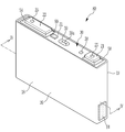
도 1은 본 발명의 일 실시 예에 따른 전지 셀의 사시도이고, 도 2는 도 1의 전지 셀을 IV-IV 선을 따라 자른 단면도이다.1 is a perspective view of a battery cell according to an embodiment of the present invention, and FIG. 2 is a cross-sectional view of the battery cell of FIG. 1 taken along line IV-IV.
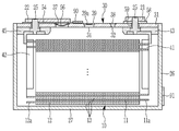
도 1 및 도 2에 도시된 바와 같이, 본 발명의 일 실시 예에 따른 전지 셀(80)은 전극 조립체(10)와, 전극 조립체(10)를 수용하기 위한 케이스(26)를 포함하며, 케이스(26)는 전해액을 수용한다. 전지 셀(80)은 또한 케이스(26)의 개구부를 밀봉하기 위한 캡 조립체(30)를 포함할 수 있다. 전지 셀(80)은 각형을 가지도록 구성된 리튬 이온 이차전지의 비 제한적인 예로서 설명될 것이다.1 and 2, the
전극 조립체(10)는 양극(11)과 음극(12) 사이에 세퍼레이터(13)를 두고, 나선형으로 권취함으로써 젤리 롤형 전극 조립체로 형성될 수 있다. 양극(11)과 음극(12)은 각각, 활성 물질(active material)이 코팅될되는, 얇은 금속 호일(metal foil)로 형성된 집전체(current collector)의 코팅 영역을 포함할 수 있으며, 활성 물질이 코팅되지 않은 집전체의 양극 비코팅 영역(11a) 및 음극 비코팅 영역(12a)을 각각 포함할 수 있다. 양극(11)의 코팅 영역은 알루미늄 호일과 같은 금속 호일로 형성된 기재에 전이 금속 산화물(transition metal oxide)과 같은 활성 물질을 코팅함으로써 형성될 수 있으나, 본 발명의 실시 예가 이에 의해 한정되는 것은 아니다. 또한, 음극(12)의 코팅 영역은 구리 또는 니켈 호일과 같은 금속 호일로 형성된 기재에 탄소, 흑연 등과 같은 활성 물질을 코팅함으로써 형성될 수 있으나, 본 발명의 실시 예악 이에 의해 한정되는 것은 아니다.The
양극 비코팅 영역(11a)은 양극(11)의 길이 방향으로 양극(11)의 일측 단부에 형성될 수 있고, 음극 비코팅 영역(12a)은 음극(12)의 길이 방향으로 음극(12)의 일측 단부에 형성될 수 있다. 양극 비코팅 영역(11a)과 음극 비코팅 영역(12a)은 코팅 영역들과 서로 반대되는 면 상에 위치할 수 있다. 또한, 세퍼레이터(13)는 복수의 세퍼레이터를 포함할 수 있으며, 이들은 양극(11), 음극(12) 및 세퍼레이터(13)가 교대로 위치된 후에 나선형으로 권취될 수 있다. 그러나, 본 발명의 실시 예가 이로 한정되는 것은 아니어서, 전극 조립체(10)는 양극(11), 세퍼레이터(13) 및 음극(12)이 반복적으로 적층된 복수의 시트를 포함하는 구조를 가지도록 구성될 수 있다. The positive electrode
전극 조립체(10)는 전해액과 함께 케이스(26) 내에 수용될 수 있다. 전해액은 EC(Ethylene Carbonate), PC(propylene carbonate), DEC(diethyl cabonate), EMC(Ethyl Methyl Carbonate) 등의 유기 용매와 LiPF6(Lithium Hexafluorophosphate), LiBF4(Lithium tetrafluoroborate) 등의 리튬 염(lithium salt)으로 이루어질 수 있다. 전해액은 액체, 고체 또는 겔 상태일 수 있다. 케이스(26)는 대략 직육면체 형상으로 구성될 수 있으며, 일면에 개구부가 형성될 수 있다. 케이스(26)는 알루미늄과 같은 금속으로 형성될 수 있다.The
케이스(26)는 대략 직사각형의 바닥면(27)을 포함하고, 넓은 측면(18, 19)인 한 쌍의 제1 측벽들과 좁은 측면인 한 쌍의 제2 측벽들은 포함하며, 전극 조립체(10)를 수용하기 위한 공간을 형성하기 위해 제1 및 제2 측벽들은 각각 바닥면(27)의 단부에 수직인 방향으로 연장된다. 제1 측벽들(18, 19)은 서로 마주 보도록 배치될 수 있으며, 제2 측벽들도 서로 마주 보도록 배치될 수 있고 제1 측벽들(18, 19)에 연결될 수 있다. 바닥면(27)과 제1 측벽들(18, 19)이 서로 연결되는 엣지의 길이는 바닥면(27)과 제2 측벽들이 사러 연결되는 엣지의 길이보다 길 수 있다. 바람직하게는, 인접한 제1 및 제2 측벽은 대략 90 °의 각도로 둘러싸고 있다. The
캡 조립체(30)는 케이스(26)에 결합되어 케이스(26)의 개구부를 덮는 캡 플레이트(31)를 포함할 수 있으며, 캡 플레이트(31)로부터 돌출되어 양극(11) 및 음극(12)에 각각 전기적으로 연결되는 양극 단자(21)(제1 단자) 및 음극 단자(22)(제2 단자)를 포함할 수 있다. 캡 플레이트(31)는 일 방향으로 연장되는 플레이트 형태로 이루어지며, 케이스(26)의 개구부에 접착될 수 있다. 캡 플레이트(31)는 캡 조립체(30)의 내부와 연통되는 주입구(32) 및 벤트 홀(34)을 포함할 수 있다. 주입구(32)는 전해액의 주입을 허용하도록 구성될 수 있으며, 그 위 또는 그 안에 밀봉 캡(38)이 장착될 수 있다. 또한, 벤트 홀(34)에는 소정의 압력에 의해 개방될 수 있은 노치(39a)가 형성된 벤트 부재(39)가 장착될 수 있다.The
양극 단자(21) 및 음극 단자(22)는 캡 플레이트(31)로부터 상방으로 돌출되도록 장착될 수 있다. 양극 단자(21)는 집전 탭(41)을 통해 양극(11)과 전기적으로 연결될 수 있고, 음극 단자(22)는 집전 탭(42)을 통해 음극(12)과 전기적으로 연결될 수 있다. 양극 단자(21)와 집전 탭(41)을 전기적으로 연결하기 위한 단자 연결 부재(25)는 양극 단자(21)와 집전 탭(41) 사이에 장착될 수 있다. 단자 연결 부재(25)는 양극 단자(21)에 형성된 홀에 삽입되어 그 하부가 집전 탭(41)에 용접될 수 있다.The
단자 연결 부재(25)와 캡 플레이트(31) 사이에는 밀봉용 가스켓(59)이 단자 연결 부재(25)가 관통하는 홀에 삽입되어 장착될 수 있다. 또한, 단자 연결 부재(25)의 하부가 삽입될 수 있는 하부 절연 부재(43)가 캡 플레이트(31)의 하부에 장착될 수 있다. 양극 단자(21)와 캡 플레이트(31) 사이에는 양극 단자(21)와 캡 플레이트(31)를 전기적으로 연결하기 위한 연결 플레이트(58)가 장착될 수 있다.Between the
단자 연결 부재(25)는 연결 플레이트(58)에 삽입될 수 있다. 따라서, 캡 플레이트(31)와 케이스(26)는 양극으로 대전될 수 있다.The
음극 단자(22)와 집전 탭(42) 사이에는, 양극 단자(21)의 단자 연결 부재(25)와 유사한, 음극 단자(22)와 집전 탭(42)을 전기적으로 연결하기 위한 단자 연결 부재(25)가 설치될 수 있다. 단자 연결 부재(25)는 음극 단자(22)에 형성된 홀에 삽입되어, 단자 연결 부재(25)의 상부와 하부가 각각 음극 단자(22) 및 집전 탭(42)에 용접될 수 있다. 음극 단자(22)와 캡 플레이트(31) 사이에는, 양극 단자(21)의 가스켓(59)과 유사한, 밀봉용 가스켓이 단자 연결 부재(25)가 관통하는 홀에 삽입되어 장착될 수 있다. 또한, 캡 플레이트(31)의 하부에는 음극 단자(22)와 집전 탭(42)을 캡 플레이트(31)와 절연하기 위한 하부 절연 부재(45)가 장착될 수 있다.Between the
음극 단자(22)와 캡 플레이트(31) 사이에는 음극 단자(22)와 캡 플레이트(31)를 전기적으로 절연시키기 위한 상부 절연 부재(54)가 장착될 수 있다. 단자 연결 부재(25)는 상부 절연 부재(54)에 형성된 홀에 삽입될 수 있다. 캡 조립체(30)는 단락 홀(37)과, 단락 홀(37)에 설치되어 양극(11)과 음극(12)을 단락시킬 수 있은 단락 부재(56)를 포함할 수 있다. 단락 부재(56)는 그 일부가 상부 절연 부재(54)와 캡 플레이트(31) 사이에 위치할 수 있고, 상부 절연 부재(54)는 단락 부재(56)에 대응하는 일부 영역에 컷 아웃(cutout)을 갖도록 구성될 수 있다. 단락 부재(56)는 컷 아웃을 통해 노출된 음극 단자(22)와 중첩될 수 있으며, 단독으로 위치될 수도 있다. An upper insulating
또한, 단락 부재(56)는 음극 단자(22)와 벤트 홀(34) 사이에 있을 수 있으며, 벤트 홀(34)보다 음극 단자(22)에 더 가까이 위치할 수도 있다. 단락 부재(56)는 전극 조립체(10) 측으로 볼록하게 만곡된 만곡부를 포함할 수 있으며, 만곡부의 외측에 형성되어 캡 플레이트(31)에 고정되는 가장자리부를 포함할 수 있다. 단락 부재(56)는 전지 셀(80)의 내부 압력이 상승하면 단락을 일으키도록 변형될 수 있다. 전지 셀(80)의 원치 않는 반응에 의해 가스가 발생하면 전지 셀(80)의 내부 압력이 상승할 수 있다. 전지 셀(80)의 내부 압력이 일정 수준(예를 들어, 기 설정된 수준) 이상으로 상승되면 단락 부재(56)의 만곡부는 압력에 의해 반대 방향을 향해(예를 들어, 음극 단자(22)를 향해) 볼록하게 만곡되도록 변형될 수 있으며, 이로 인해 단락 부재(56)는 음극 단자(22)에 접하여 단락을 일으킨다. Further, the shorting
도 1 및 도 2에 도시된 예시적인 실시 예에 따르면, 캡 플레이트(31)의 일부에 제1 코팅(90)이 배치되고, 케이스(26)의 측면의 일부에 제2 코팅(91)이 배치될 수 있다. 그러나, 코팅(90,91)의 배치는 이에 한정되는 것은 아니어서, 변경이 가능하다. 코팅들(90, 91)은 전지 시스템의 하우징 내에서 공기에 접할 수 있는 전지 셀(80)의 임의의 표면 상에 증착될 수 있으며, 이는 이후 상세히 설명될 것이다.1 and 2, the
코팅들(90, 91)은 온도가 소정 온도를 초과할 때 적어도 하나의 가스 종을 방출하도록 구성된다. The
제1 및 제2 코팅(90, 91)은 동일한 조성을 가질 수 있다. 이 경우, 제1 및 제2 코팅(90, 91)은 동일한 소정의 온도를 초과할 때 동일한 가스 종을 방출할 수 있다.The first and
제1 및 제2 코팅(90, 91)은 서로 다른 조성을 가질 수도 있다. 이 경우, 제1 및 제2 코팅(90, 91)은 상이한 온도에서 상이한 가스 종을 방출할 수 있다.The first and
이러한 코팅들(90, 91)은 (i) 소정 온도에서 화학 반응에 의해 적어도 하나의 가스 종을 생성하는 반응 시스템, (ii) 소정 온도에서 비등점 또는 승화점을 갖는 화합물(여기서, 화합물의 기상(gaseous phase)은 특정 가스 종에 대응된다), 및 (iii) 특정 가스 종을 포함하며, 소정 온도에서 해당 가스 종을 방출하도록 구성된 매트릭스 시스템 중 적어도 하나를 포함할 수 있다. These
전술한 바와 같이, 전지 셀(80)의 임의의 표면에 소정 온도에서 특정 가스 종을 방출하는 코팅(90, 91)들을 제공함으로써, 각 전지 셀(80)의 과열 감시가 쉽게 이루어질 수 있다.As described above, by providing
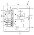
도 3은 본 발명의 일 실시 예에 따른 전지 시스템(100)의 평면도를 매우 개략적으로 도시한다. 전지 시스템(100)은, 전지 모듈(110)을 구성하도록 조립되며 전기적으로 상호 연결되는 전지 셀(380)들의 스택을 포함한다. 전지 모듈(110)을 구성하는 전지 셀들(380)은, 도 1 및 도 2를 참조하여 상술한 전지 셀(80)과 유사할 수 있다. 냉각 판(382)은 인접하는 전지 셀들(380) 사이에 배치된다. 도 1의 실시 예의 코팅(90)과 유사한 코팅(390)이 각 전지 셀(380)의 상부면에 배치될 수 있다.3 is a very schematic plan view of a
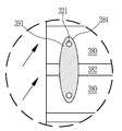
인접한 전지 셀들(380)의 음극 및 양극 단자들(321, 322)은 고전류 커넥터들(384)에 의해 상호 연결된다. 도 4에 상세히 도시된 바와 같이, 온도가 소정 온도를 초과할 때 적어도 하나의 가스 종의 방출을 허용하는 코팅(391)이 전류 커넥터(384)의 상부 표면 전체에 제공될 수 있다. 이에 따라, 전지 셀(380) 각각의 과열 감시가 쉽게 이루어질 수 있으며, 단일 전류 커넥터에서의 과열도 쉽게 검출될 수 있다.The negative and
또한, 전지 모듈(110)은 복수의 고전류 커넥터(384)에 의해 제1 시스템 단자(112)와 제2 시스템 단자(114) 사이에서 상호 연결된다. 전지 모듈(110)과 시스템 단자들(112, 114) 사이의 상호접속(interconnection)은, 전류 센서(116) 및 시스템 단자들(112, 114)을 전지 모듈(110)과 각각 연결 또는 분리하기 위한 릴레이들(118, 119)를 더 포함할 수 있다. In addition, the
전지 시스템(100)은 전지 관리 시스템(battery management system, BMS)(120)을 더 포함한다. BMS(120)는 적절한 통신 버스, 예를 들어, SPI 또는 CAN 인터페이스를 통해 다양한 전기 소비자의 제어기와 통신할 수 있다. BMS(120)는 각 전지 모듈(110)(미도시)의 셀 감독 회로(cell supervision circuit, CSC)와 더 통신할 수 있다. BMS(120)는 전지 셀들(380)이 그들의 안전 동작 영역(safe operating area, SOA)을 벗어나 동작하는 것으로부터 보호하고, 전지 셀들(380)의 상태를 모니터링하며, 보조 데이터를 계산하고, 이들을 보고하는 등, 전지 시스템(100)을 관리하기 위한 기능들을 수행할 수 있다. BMS는 전지 분리 유닛(battery disconnect unit, BDU)과 통신할 수도 있다. The
전지 시스템(100)은 팬(130)을 더 포함할 수 있다.The
BMS(120)는 데이터 라인(131)을 통해, 팬(130)의 동작 및 상태를 조절하거나 감독할 수 있다. 팬(130)에서 전지 모듈(110)과 마주하는 면에는 팬(130)의 공기가 유입되는 유입구(inlet opening)(132)가 형성된다. 배출구(outlet opening)(133)는 팬(130)에서 유입구(132)에 대향하는 면에 위치되고, 유동 채널(134)을 향해 개방된다. 가스 센서(140)는 유동 채널(134) 내에 위치될 수 있다.The
전지 시스템(100)은 전지 모듈(110), BMS(120), 팬(130) 및 가스 센서(140)를 수용하기 위한 하우징(150)을 더 포함할 수 있다. 하우징(150)은 강성(rigid) 프레임 구조와 전지 시스템(100)을 밀폐하기 위한 커버 부재들을 포함할 수 있다. 하우징(150)은 전기 차량(미도시)의 하부에 장착될 수 있다. 전지 시스템(100)은, 온도가 소정 온도를 초과할 때 적어도 하나의 가스 종의 방출을 허용하는 코팅(392)을 포함할 수 있으며, 코팅(392)은 하우징(150)의 내부 표면 상에 배치된다. The
팬(130)이 스위치 온 될 때, 하우징(150) 내에 화살표(160)로 표시된 순환 공기 흐름이 형성된다. 공기 흐름은 코팅들(390, 391, 392)이 도포된 각 표면 위를 흐르며, 가스 센서(140)가 이 공기 흐름 내에 배치된다. 코팅(390, 391, 392)에서의 온도가 특정 온도를 초과하는 경우, 각 코팅(390, 391, 392)은 특정 가스 종을 방출할 수 있으며, 각 코팅(390, 391, 392)에서 방출된 가스 종은 공기 흐름에 의해 가스 센서(140)로 전달될 수 있다. 가스 센서(140)는 각 코팅(390, 391, 392)이 방출하는 가스 종을 검출할 수 있도록 선택될 수 있다. When the
코팅들(390, 391, 392)은 동일한 조성을 가질 수 있다. 이 경우, 코팅들(390, 391, 392)은 동일한 소정의 온도를 초과할 때 동일한 가스 종을 방출할 수 있다. The
코팅들(390, 391, 392)은 서로 다른 조성을 가질 수도 있다. 이 경우, 코팅들(390, 391, 392)은 상이한 온도에서 상이한 가스 종을 방출할 수 있다. 이 경우, 가스 센서(140)는 코팅들(390, 391, 392)에 의해 방출되는 상이한 가스 종들을 검출할 수 있도록 구성되거나, 코팅들(390, 391, 392)에 의해 방출되는 상이한 가스 종들을 검출하기 위해 하우징(150) 내에 복수의 가스 센서(140)가 배치될 수도 있다. The
가스 센서(140)는 코팅(390, 391, 392)에 의해 방출된 특정 가스 종이 검출되면, 제어 신호(control signal, CS)를 BMS(120)에 전송한다. 이에 따라, BMS(120)는 가스 센서(140)로부터의 제어 신호(CS)의 수신에 응답하여, BDU(미도시)에 분리 신호(disconnect signal, DS)를 전달할 수 있다. 또한, BDU는 분리 신호(DS)에 응답하여 전지 모듈(110)의 시스템 단자들(112, 114) 중 어느 하나를 전지 모듈(110)과 분리하도록 릴레이들(118, 119)을 제어할 수 있다. The
전지 시스템(100)의 과열 상태는 전지 시스템(100) 내에 적어도 하나의 가스 종의 발생을 야기할 수 있으며, 전지 시스템(100)은 해다 가스 종의 농도를 전지 시스템(100)의 과열 상황 인지에 활용할 수도 있다. 이 경우, 가스 센서(140)는 과열 상황에서 코팅(390, 391, 392)에 의해 방출되는 가스 종 외에, 과열 상황에서 하우징(150) 내에서 발생할 수 있는 다른 종류의 가스 종의 검출에 응답하여 제어 신호(CS)를 전송할 수 있다. 예를 들어, 가스 센서(140)는 과열 상황에서 코팅(390, 391, 392)에 의해 방출될 수 있는 가스 종들과 과열 상황에 의해 하우징(150) 내에서 발생할 수 있는 다른 종류의 가스 종들 중 하나 이상의 가스 종의 초과 농도를 검출하는 것에 은답하여, 대응하는 제어 신호(CS)를 전송할 수 있다. 또한, 예를 들어, 가스 센서(140)는 과열 상황에서 코팅(390, 391, 392)에 의해 방출될 수 있는 가스 종들과 과열 상황에 의해 하우징(150) 내에서 발생할 수 있는 다른 종류의 가스 종들 중 복수의 가스 종의 기 설정된 조합의 초과 농도 검출에 응답하여, 대응하는 제어 신호(CS)를 전송할 수도 있다.The overheating state of the
아래의 표 1은, 전지 시스템(100)의 과열 상황에서 통상적으로 발생할 수 있는 가스 종들을 각 과열 상황 별로 나타낸 것이다. 과열 상황의 검출을 단순화하고 혼선을 피하기 위해, 표 1에 기재된 가스 종들은, 코팅(390, 391, 392)에 의해 방출되는 가스 종들과 타입이나 농도가 다를 수 있으나, 본 발명의 실시 예가 이에 의해 제한되는 것은 아니다. Table 1 below shows gas species that may normally occur in the overheating situation of the
플라스틱 연기Hot spot,
Plastic smoke
(열 폭주)Cell discharge
(Thermal runaway)
전술한 바와 같이, 실시 예에 따른 전지 시스템(100)에서는 하우징(150) 내에 간단하지만 성능이 좋은 온도 관리 시스템을 구비할 수 있다. 특히, 이를 이용하여 하우징(150) 내에서 온도 센서들에 의해 감지가 어려운 영역에서의 과열 상황 검출이 가능하다. As described above, in the
또한, 하우징(150) 내부에 적절한 순환 공기 흐름을 발생시키고, 순환 공기 흐름 내에 온도에 따라 특정 가스 종을 방출하도록 설계된 코팅(390, 391, 392)을 배치함으로써, 가스 센서(140)를 코팅(390, 391, 392) 옆에 배치하지 않고도 가스 종의 검출이 가능하다. 또한, 가스 센서(140)를 순환되는 공기 흐름 내에 배치함으로써, 단일의 가스 센서(140)로부터 여러 위치에서의 과열 상황을 검출하는 것이 가능하다. In addition, the
냉각 판(382)과 같은 냉각 요소에 소정 온도에서 특정 가스 종을 방출하는 코팅이 추가로 배치될 수도 있다. 이 경우, 전지 시스템(100)은 전지 셀(380)에 유해한 온도 상승이 발생하기 전에 냉각 요소의 고장을 검출할 수 있다. A cooling element, such as a
전술한 구조의 전지 시스템(100)은, 차량에 장착되어 사용될 수 있다. The
도 5는 본 발명의 일 실시 예에 따른 전지 시스템의 과열 상황을 검출하는 방법을 설명하는 흐름도이다. 도 5의 과열 상황 검출 방법은, 도 3 및 도 4를 참조하여 설명한 전지 시스템(100)에 의해 수행될 수 있다. 5 is a flowchart illustrating a method of detecting an overheating situation of a battery system according to an embodiment of the present invention. The overheating condition detection method of FIG. 5 may be performed by the
도 5의 흐름도에 개략적으로 도시된 바와 같이, 가스 센서(140)는 코팅(390, 391, 392)에 의해 방출된 가스 종이 검출되면, 제어 신호(control signal, CS)를 출력하고(단계 400), BMS(120)로 제어 신호(CS)가 전달된다(단계 410). As schematically illustrated in the flow chart of FIG. 5, the
제어 신호(CS)에 응답하여, BMS(120)는 전지 분리 유닛(BDU)에 의해 시스템 단자들(112, 114) 중 어느 하나와 전지 모듈(110) 간의 분리를 개시한다(단계 420). 즉, BMS(120)는 제어 신호(CS)의 수신에 응답하여 분리 신호(DS)를 BDU로 전달한다. In response to the control signal CS, the
분리 신호(DS)에 응답하여, BDU는 예를 들어 릴레이(118)를 스위칭함으로써 제1 및 제2 시스템 단자들(112, 114) 중 적어도 하나를 전지 모듈(110)로부터 분리한다(단계 430). In response to the disconnect signal DS, the BDU disconnects at least one of the first and
전술한 바와 같이, BMS(120)는 가스 센서(140)의 제어 신호(CS)에 기초하여 전지 시스템(100)의 과열 상황의 존재를 판정하고, 전지 모듈(110)의 분리와 같이, 과열 상황에 대한 적어도 하나의 보호 조치를 제어한다. As described above, the
전지 시스템(100)에서 제어 신호(CS)의 전송은 전지 시스템(100)의 동작에 심각하게 개입할 수 있다. 따라서, 정상 동작 중인 전지 시스템(100)을 오작동으로 잘못 인지하는 오 탐지(false positive) 이벤트는 어떠한 비용을 치르더라도 방지되어야 한다. 또한, 전지 시스템(100) 내 부품의 긴급한 장애 징후는 무시되어서는 안되며, 장애 징후가 보일 경우 전지 시스템(100)은 가능한한 빠른 시간 내에 안전한 상태로 진입하여, 전지 화재 등과 같은 재해적인 사건이 일어나는 것을 방지해야 한다. 본 발명의 실시 예에 따른 전지 시스템(100) 및 이의 과열 상황 검출 방법은, 소정 온도에 도달해야만 특정 가스 종을 방출하는 코팅을 이용하여 과열 상황을 인지함으로써, 전지 시스템(100)의 과열 상황의 초기 징후를 효과적으로 검출할 뿐만 아니라, 전지 시스템(100)의 안전에 중요한 부품들의 수명을 평가하기 위한 신뢰성 있는 솔루션을 제공할 수 있다. The transmission of the control signal CS in the
지금까지 참조한 도면과 기재된 발명의 상세한 설명은 단지 본 발명의 예시적인 것으로서, 이는 단지 본 발명을 설명하기 위한 목적에서 사용된 것이지 의미 한정이나 특허청구범위에 기재된 본 발명의 범위를 제한하기 위하여 사용된 것은 아니다. 그러므로 본 기술 분야의 통상의 지식을 가진 자라면 이로부터 다양한 변형 및 균등한 타 실시 예가 가능하다는 점을 이해할 것이다. 따라서, 본 발명의 진정한 기술적 보호 범위는 첨부된 특허청구범위의 기술적 사상에 의해 정해져야 할 것이다.The drawings referenced so far and the detailed description of the described invention are merely illustrative of the present invention, which are used only for the purpose of illustrating the present invention and are used to limit the scope of the present invention as defined in the claims or the claims. It is not. Therefore, those skilled in the art will understand that various modifications and other equivalent embodiments are possible. Therefore, the true technical protection scope of the present invention should be determined by the technical spirit of the appended claims.
10: 전극 조립체
11: 양극
11a: 양극 비코팅 영역
12: 음극
12a: 음극 비코팅 영역
13: 세퍼레이터
18: 제1 측면
19: 제2 측면
21, 321: 양극 셀 단자
22, 322: 음극 셀 단자
25: 단자 연결 부재
26: 케이스
27: 바닥면
30: 캡 조립체
31: 캡 플레이트
32: 주입구
34: 벤트 홀
37: 단락 홀
38: 밀봉 캡
39: 벤트 부재
39a: 노치
41, 42: 집전 탭
43, 45: 하부 절연 부재
54: 상부 절연 부재
56: 단락 부재
58: 연결 평면
59: 가스켓
80, 380: 전지 셀
90, 91, 390, 391, 392: 가스 종을 방출하는 코팅
100: 전지 시스템
110: 전지 모듈
112, 114: 시스템 단자
116: 전류 센서
118, 119: 릴레이
120: 전지 관리 시스템, BMS
130: 팬
132: 유입구
133: 배출구
134: 유동 채널
140: 가스 센서
150: 하우징
160: 순환 공기 흐름
382: 냉각 판
384: 고전류 커넥터10: electrode assembly
11: anode
11a: anode uncoated region
12: cathode
12a: cathode uncoated region
13: separator
18: first side
19: second side
21, 321: positive cell terminal
22, 322: negative cell terminal
25: terminal connection member
26: case
27: bottom surface
30: cap assembly
31: cap plate
32: inlet
34: Bent Hall
37: short hole
38: sealing cap
39: no vent
39a: Notch
41, 42: current collector tab
43, 45: lower insulating member
54: upper insulating member
56: short circuit member
58: Connection plane
59: gasket
80, 380: battery cell
90, 91, 390, 391, 392: coatings that emit gas species
100: battery system
110: battery module
112, 114: system terminal
116: current sensor
118, 119: relay
120: battery management system, BMS
130: fan
132: inlet
133: outlet
134: flow channel
140: gas sensor
150: housing
160: circulating air flow
382: cooling plate
384: high current connector
Claims (11)
각각이 복수의 전지 셀을 포함하는 적어도 하나의 전지 모듈;
적어도 하나의 가스 센서; 및
상기 적어도 하나의 전지 모듈과 상기 적어도 하나의 가스 센서를 수용하기 위한 하우징을 포함하고,
상기 적어도 하나의 전지 모듈의 외부 표면의 적어도 일부 및/또는 상기 하우징의 내부 표면의 적어도 일부는, 온도가 소정 온도를 초과할 때 적어도 하나의 가스 종을 방출하도록 구성된 코팅에 의해 커버되고,
상기 적어도 하나의 가스 센서는 상기 적어도 하나의 가스 종을 검출하도록 구성된, 전지 시스템. In a vehicle battery system,
At least one battery module, each of which includes a plurality of battery cells;
At least one gas sensor; And
And a housing for accommodating the at least one battery module and the at least one gas sensor,
At least a portion of the outer surface of the at least one battery module and / or at least a portion of the inner surface of the housing is covered by a coating configured to release at least one gas species when the temperature exceeds a predetermined temperature,
Wherein the at least one gas sensor is configured to detect the at least one gas species.
상기 코팅은,
화학 반응에 의해 상기 소정 온도에서 상기 적어도 하나의 가스 종을 생성하는 반응 시스템,
상기 소정 온도에서 비등점 또는 승화점을 갖는 화합물, 및
상기 적어도 하나의 가스 종을 포함하고, 상기 소정 온도에서 상기 적어도 하나의 가스 종을 방출하도록 구성된 매트릭스 시스템
중 적어도 하나를 포함하거나, 적어도 하나로 구성되며,
상기 화합물의 기상은 상기 적어도 하나의 가스 종에 대응되는, 전지 시스템. According to claim 1,
The coating,
A reaction system that produces the at least one gas species at the predetermined temperature by a chemical reaction,
A compound having a boiling point or a sublimation point at the predetermined temperature, and
A matrix system comprising the at least one gas species and configured to release the at least one gas species at the predetermined temperature
It comprises at least one of, or consists of at least one,
Wherein the gas phase of the compound corresponds to the at least one gas species.
상기 코팅은,
상기 전지 셀의 외부 표면,
상기 전지 시스템의 전기 배선, 및
상기 복수의 전지 셀 및 상기 적어도 하나의 전지 모듈을 위한 냉각 소자
중 적어도 하나에 제공되는, 전지 시스템. According to claim 1,
The coating,
The outer surface of the battery cell,
Electrical wiring of the battery system, and
Cooling element for the plurality of battery cells and the at least one battery module
Provided in at least one of the battery system.
상기 전기 배선은, 전류 커넥터를 포함하고, 상기 코팅은 상기 전류 커넥터 상에 제공되는, 전지 시스템. According to claim 3,
Wherein the electrical wiring includes a current connector, and the coating is provided on the current connector.
상기 하우징 내에 순환 공기 흐름을 형성하기 위한 수단을 더 포함하며,
상기 순환 공기 흐름은 상기 코팅이 도포된 표면들 위를 흐르고,
상기 적어도 하나의 가스 센서는 상기 순환 공기 흐름 내에 배치되는, 전지 시스템. According to claim 1,
Means for forming a circulating air stream in the housing,
The circulating air stream flows over the surfaces to which the coating is applied,
Wherein the at least one gas sensor is disposed within the circulating air stream.
상기 순환 공기 흐름을 형성하기 위한 수단은 팬을 포함하고,
상기 적어도 하나의 가스 센서는 상기 팬을 떠나는 공기 흐름 내에 위치되는, 전지 시스템. The method of claim 5,
The means for forming the circulating air stream includes a fan,
Wherein the at least one gas sensor is located in an air stream leaving the fan.
상기 적어도 하나의 가스 센서에 연결된 전지 관리 시스템을 더 포함하며,
상기 적어도 하나의 가스 센서는 상기 적어도 하나의 가스 종의 검출에 응답하여 상기 전지 관리 시스템에 제어 신호를 전달하는, 전지 시스템. According to claim 1,
Further comprising a battery management system connected to the at least one gas sensor,
And the at least one gas sensor transmits a control signal to the battery management system in response to detection of the at least one gas species.
제1 및 제2 시스템 단자 중 적어도 하나와 상기 적어도 하나의 전지 모듈 사이에 상호 연결된 전지 분리 유닛을 더 포함하며,
상기 전지 관리 시스템은 상기 제어 신호의 수신에 응답하여 분리 신호를 상기 전지 분리 유닛으로 전송하도록 구성되며,
상기 전지 관리 유닛은 상기 분리 신호에 응답하여 상기 적어도 하나의 전지 모듈을 상기 제1 및 제2 시스템 단자 중 적어도 하나와 분리하도록 구성되는, 전지 시스템. The method of claim 7,
And a battery separation unit interconnected between at least one of the first and second system terminals and the at least one battery module,
The battery management system is configured to transmit a separation signal to the battery separation unit in response to the reception of the control signal,
And the battery management unit is configured to separate the at least one battery module from at least one of the first and second system terminals in response to the separation signal.
상기 전지 시스템은, 각각이 복수의 전지 셀을 포함하는 적어도 하나의 전지 모듈, 적어도 하나의 가스 센서, 상기 적어도 하나의 전지 모듈과 상기 적어도 하나의 가스 센서를 수용하기 위한 하우징, 및 전지 관리 시스템을 포함하고,
상기 적어도 하나의 전지 모듈의 외부 표면의 적어도 일부 및/또는 상기 하우징의 내부 표면의 적어도 일부는, 온도가 소정 온도를 초과할 때 적어도 하나의 가스 종을 방출하도록 구성된 코팅에 의해 커버되고, 상기 적어도 하나의 가스 센서는 상기 적어도 하나의 가스 종을 검출하도록 구성되며,
상기 방법은,
상기 가스 센서로 상기 적어도 하나의 가스 종을 검출하는 단계; 및
상기 적어도 하나의 가스 종의 검출에 응답하여, 상기 가스 센서로부터 상기 전지 관리 시스템으로 적어도 하나의 제어 신호를 전송하는 단계를 포함하는, 방법. In the method for detecting the overheating condition of the battery system,
The battery system includes at least one battery module, a gas sensor, a housing for accommodating the at least one battery module and the at least one gas sensor, and a battery management system, each of which includes a plurality of battery cells. Including,
At least a portion of the outer surface of the at least one battery module and / or at least a portion of the inner surface of the housing is covered by a coating configured to release at least one gas species when the temperature exceeds a predetermined temperature, and the at least One gas sensor is configured to detect the at least one gas species,
The above method,
Detecting the at least one gas species with the gas sensor; And
And in response to detecting the at least one gas species, transmitting at least one control signal from the gas sensor to the battery management system.
상기 방법은,
상기 전지 시스템 내에서의 과열 상황의 존재를 결정하는 단계; 및
상기 과열 상황에 대한 하나 이상의 보호 조치를 제어하는 단계를 더 포함하는, 방법. The method of claim 10,
The above method,
Determining the presence of an overheating situation in the battery system; And
And controlling one or more protective measures for the overheating situation.
Priority Applications (1)
| Application Number | Priority Date | Filing Date | Title |
|---|---|---|---|
| US16/589,509 US10992013B2 (en) | 2018-10-05 | 2019-10-01 | Battery system for a vehicle and method for detecting an overheat situation of the battery system |
Applications Claiming Priority (2)
| Application Number | Priority Date | Filing Date | Title |
|---|---|---|---|
| EP18198757.9A EP3633754B1 (en) | 2018-10-05 | 2018-10-05 | Battery system for a vehicle and method for detecting an overheat situation of the battery system |
| EP18198757.9 | 2018-10-05 |
Publications (1)
| Publication Number | Publication Date |
|---|---|
| KR20200040190A true KR20200040190A (en) | 2020-04-17 |
Family
ID=63787762
Family Applications (1)
| Application Number | Title | Priority Date | Filing Date |
|---|---|---|---|
| KR1020190114258A KR20200040190A (en) | 2018-10-05 | 2019-09-17 | Battery system for vehicle and method for detecting overheat situation of battery system |
Country Status (4)
| Country | Link |
|---|---|
| EP (1) | EP3633754B1 (en) |
| KR (1) | KR20200040190A (en) |
| HU (1) | HUE053646T2 (en) |
| PL (1) | PL3633754T3 (en) |
Cited By (1)
| Publication number | Priority date | Publication date | Assignee | Title |
|---|---|---|---|---|
| WO2022045589A1 (en) * | 2020-08-31 | 2022-03-03 | 주식회사 엘지에너지솔루션 | Battery system and battery module evaluation method capable of detecting damaged battery cell |
Families Citing this family (3)
| Publication number | Priority date | Publication date | Assignee | Title |
|---|---|---|---|---|
| FR3115933A1 (en) * | 2020-10-29 | 2022-05-06 | Commissariat à l'Energie Atomique et aux Energies Alternatives | Power supply system |
| EP4216334A1 (en) | 2022-01-20 | 2023-07-26 | Abb Schweiz Ag | Battery cell, battery module, battery pack, battery management system and method for determining a value of at least one wear parameter of a battery cell |
| CN116840423B (en) * | 2023-08-29 | 2024-02-20 | 宁德时代新能源科技股份有限公司 | Energy storage device and gas concentration detection method thereof |
Family Cites Families (2)
| Publication number | Priority date | Publication date | Assignee | Title |
|---|---|---|---|---|
| DE102012215883A1 (en) * | 2012-09-07 | 2014-03-13 | Robert Bosch Gmbh | Energy storage e.g. lithium ion battery mounted in e.g. electric vehicle, has detection unit that is provided for detecting component located within housing or reaction product of component, during operation of energy storage |
| WO2016086184A1 (en) * | 2014-11-25 | 2016-06-02 | American Lithium Energy Corporation | Rechargable battery with internal current limiter and interrupter |
-
2018
- 2018-10-05 HU HUE18198757A patent/HUE053646T2/en unknown
- 2018-10-05 EP EP18198757.9A patent/EP3633754B1/en active Active
- 2018-10-05 PL PL18198757T patent/PL3633754T3/en unknown
-
2019
- 2019-09-17 KR KR1020190114258A patent/KR20200040190A/en unknown
Cited By (1)
| Publication number | Priority date | Publication date | Assignee | Title |
|---|---|---|---|---|
| WO2022045589A1 (en) * | 2020-08-31 | 2022-03-03 | 주식회사 엘지에너지솔루션 | Battery system and battery module evaluation method capable of detecting damaged battery cell |
Also Published As
| Publication number | Publication date |
|---|---|
| EP3633754B1 (en) | 2021-01-27 |
| PL3633754T3 (en) | 2021-08-30 |
| HUE053646T2 (en) | 2021-07-28 |
| EP3633754A1 (en) | 2020-04-08 |
Similar Documents
| Publication | Publication Date | Title |
|---|---|---|
| US10992013B2 (en) | Battery system for a vehicle and method for detecting an overheat situation of the battery system | |
| KR20200040190A (en) | Battery system for vehicle and method for detecting overheat situation of battery system | |
| KR102259217B1 (en) | Battery System and Vehicle Comprising the Same | |
| KR102421779B1 (en) | Battery system | |
| WO2012014398A1 (en) | Battery module and battery pack using same | |
| US20110236727A1 (en) | Secondary battery pack | |
| KR20190139134A (en) | Battery system and method for detection abnormal conditions thereof | |
| US10320036B2 (en) | Voltage sensing assembly and battery module including the same | |
| US20220115717A1 (en) | Apparatus for detecting thermal runaway of battery for electric vehicle | |
| US11764409B2 (en) | Battery system, method for leakage detection inside the battery system, and vehicle including the battery system | |
| CN109845024B (en) | Battery system and electric vehicle including the same | |
| KR102586103B1 (en) | Battery system, a method for leakage detection inside a battery system and a vehicle including a battery system | |
| KR20150045241A (en) | Battery cell equipped with disconnection device, and Battery module and Battery pack comprising the same | |
| US20230187773A1 (en) | Battery system with a cover element forming a venting channel | |
| KR20230034174A (en) | Battery system, method of detecting its abnomal operating condition, and electric vehicle | |
| US20230077121A1 (en) | Method of detecting an operating condition of a battery system, which may lead to a thermal runaway | |
| KR20230117669A (en) | Battery system with active cooling of venting channel | |
| KR20200092872A (en) | Method and system for preventing ingestion of contaminated ambient air into passenger compartment of vehicle in case of battery failure | |
| WO2018084439A1 (en) | Battery system | |
| EP4199210A1 (en) | Battery system with a cover element forming a venting channel | |
| CN113471641B (en) | Battery system and vehicle comprising at least one battery system | |
| US11260725B2 (en) | Method and system for preventing ingestion of contaminated ambient air into a passenger compartment of a vehicle | |
| US20230344038A1 (en) | Battery system with cooler beams | |
| US20220384923A1 (en) | Battery module and battery pack including the same | |
| US20220263154A1 (en) | Battery system and vehicle including the battery system |