KR20200039867A - Organic light emitting diode display device - Google Patents
Organic light emitting diode display device Download PDFInfo
- Publication number
- KR20200039867A KR20200039867A KR1020180118769A KR20180118769A KR20200039867A KR 20200039867 A KR20200039867 A KR 20200039867A KR 1020180118769 A KR1020180118769 A KR 1020180118769A KR 20180118769 A KR20180118769 A KR 20180118769A KR 20200039867 A KR20200039867 A KR 20200039867A
- Authority
- KR
- South Korea
- Prior art keywords
- layer
- electrode
- light emitting
- organic light
- semiconductor layer
- Prior art date
Links
- 239000004065 semiconductor Substances 0.000 claims abstract description 133
- 230000000903 blocking effect Effects 0.000 claims abstract description 83
- 239000000758 substrate Substances 0.000 claims abstract description 29
- 229910021420 polycrystalline silicon Inorganic materials 0.000 claims description 18
- 238000005538 encapsulation Methods 0.000 claims description 7
- 238000009413 insulation Methods 0.000 abstract 4
- 239000010410 layer Substances 0.000 description 314
- 239000003990 capacitor Substances 0.000 description 31
- 239000011229 interlayer Substances 0.000 description 22
- 239000010408 film Substances 0.000 description 17
- 206010047571 Visual impairment Diseases 0.000 description 13
- 239000012535 impurity Substances 0.000 description 11
- 238000002161 passivation Methods 0.000 description 10
- 239000000463 material Substances 0.000 description 9
- VYPSYNLAJGMNEJ-UHFFFAOYSA-N Silicium dioxide Chemical compound O=[Si]=O VYPSYNLAJGMNEJ-UHFFFAOYSA-N 0.000 description 8
- 238000010586 diagram Methods 0.000 description 8
- 229910052751 metal Inorganic materials 0.000 description 7
- 239000002184 metal Substances 0.000 description 7
- 229910052581 Si3N4 Inorganic materials 0.000 description 6
- LIVNPJMFVYWSIS-UHFFFAOYSA-N silicon monoxide Chemical compound [Si-]#[O+] LIVNPJMFVYWSIS-UHFFFAOYSA-N 0.000 description 6
- HQVNEWCFYHHQES-UHFFFAOYSA-N silicon nitride Chemical compound N12[Si]34N5[Si]62N3[Si]51N64 HQVNEWCFYHHQES-UHFFFAOYSA-N 0.000 description 6
- 229910052814 silicon oxide Inorganic materials 0.000 description 6
- 238000000034 method Methods 0.000 description 5
- 239000011368 organic material Substances 0.000 description 5
- 238000005192 partition Methods 0.000 description 5
- 230000000052 comparative effect Effects 0.000 description 4
- 239000010949 copper Substances 0.000 description 4
- 238000002347 injection Methods 0.000 description 4
- 239000007924 injection Substances 0.000 description 4
- 230000003071 parasitic effect Effects 0.000 description 4
- 229920005989 resin Polymers 0.000 description 4
- 239000011347 resin Substances 0.000 description 4
- 239000002356 single layer Substances 0.000 description 4
- 239000004642 Polyimide Substances 0.000 description 3
- QVGXLLKOCUKJST-UHFFFAOYSA-N atomic oxygen Chemical compound [O] QVGXLLKOCUKJST-UHFFFAOYSA-N 0.000 description 3
- 229910052760 oxygen Inorganic materials 0.000 description 3
- 239000001301 oxygen Substances 0.000 description 3
- 229920001721 polyimide Polymers 0.000 description 3
- 229910000838 Al alloy Inorganic materials 0.000 description 2
- RYGMFSIKBFXOCR-UHFFFAOYSA-N Copper Chemical compound [Cu] RYGMFSIKBFXOCR-UHFFFAOYSA-N 0.000 description 2
- 229910000881 Cu alloy Inorganic materials 0.000 description 2
- 229910001182 Mo alloy Inorganic materials 0.000 description 2
- ZOKXTWBITQBERF-UHFFFAOYSA-N Molybdenum Chemical compound [Mo] ZOKXTWBITQBERF-UHFFFAOYSA-N 0.000 description 2
- 229910052782 aluminium Inorganic materials 0.000 description 2
- XAGFODPZIPBFFR-UHFFFAOYSA-N aluminium Chemical compound [Al] XAGFODPZIPBFFR-UHFFFAOYSA-N 0.000 description 2
- 229910052802 copper Inorganic materials 0.000 description 2
- 239000011521 glass Substances 0.000 description 2
- 229910010272 inorganic material Inorganic materials 0.000 description 2
- 239000011147 inorganic material Substances 0.000 description 2
- 229910052750 molybdenum Inorganic materials 0.000 description 2
- 239000011733 molybdenum Substances 0.000 description 2
- 229920000058 polyacrylate Polymers 0.000 description 2
- GKWLILHTTGWKLQ-UHFFFAOYSA-N 2,3-dihydrothieno[3,4-b][1,4]dioxine Chemical compound O1CCOC2=CSC=C21 GKWLILHTTGWKLQ-UHFFFAOYSA-N 0.000 description 1
- 229920001609 Poly(3,4-ethylenedioxythiophene) Polymers 0.000 description 1
- 239000004952 Polyamide Substances 0.000 description 1
- 229910021417 amorphous silicon Inorganic materials 0.000 description 1
- 238000000137 annealing Methods 0.000 description 1
- 239000002131 composite material Substances 0.000 description 1
- 238000002425 crystallisation Methods 0.000 description 1
- 238000005516 engineering process Methods 0.000 description 1
- 230000005281 excited state Effects 0.000 description 1
- 230000005484 gravity Effects 0.000 description 1
- 230000005283 ground state Effects 0.000 description 1
- 230000010354 integration Effects 0.000 description 1
- 238000012986 modification Methods 0.000 description 1
- 230000004048 modification Effects 0.000 description 1
- 239000004033 plastic Substances 0.000 description 1
- 229920003023 plastic Polymers 0.000 description 1
- 229920002647 polyamide Polymers 0.000 description 1
- 229920000515 polycarbonate Polymers 0.000 description 1
- 239000004417 polycarbonate Substances 0.000 description 1
- -1 polyethylene terephthalate Polymers 0.000 description 1
- 229920000139 polyethylene terephthalate Polymers 0.000 description 1
- 239000005020 polyethylene terephthalate Substances 0.000 description 1
- 229920000642 polymer Polymers 0.000 description 1
- 239000011241 protective layer Substances 0.000 description 1
- 239000000377 silicon dioxide Substances 0.000 description 1
- 239000010409 thin film Substances 0.000 description 1
Images


Classifications
-
- H01L27/3262—
-
- H—ELECTRICITY
- H10—SEMICONDUCTOR DEVICES; ELECTRIC SOLID-STATE DEVICES NOT OTHERWISE PROVIDED FOR
- H10K—ORGANIC ELECTRIC SOLID-STATE DEVICES
- H10K59/00—Integrated devices, or assemblies of multiple devices, comprising at least one organic light-emitting element covered by group H10K50/00
- H10K59/10—OLED displays
- H10K59/12—Active-matrix OLED [AMOLED] displays
- H10K59/121—Active-matrix OLED [AMOLED] displays characterised by the geometry or disposition of pixel elements
- H10K59/1213—Active-matrix OLED [AMOLED] displays characterised by the geometry or disposition of pixel elements the pixel elements being TFTs
-
- H—ELECTRICITY
- H01—ELECTRIC ELEMENTS
- H01L—SEMICONDUCTOR DEVICES NOT COVERED BY CLASS H10
- H01L27/00—Devices consisting of a plurality of semiconductor or other solid-state components formed in or on a common substrate
- H01L27/02—Devices consisting of a plurality of semiconductor or other solid-state components formed in or on a common substrate including semiconductor components specially adapted for rectifying, oscillating, amplifying or switching and having at least one potential-jump barrier or surface barrier; including integrated passive circuit elements with at least one potential-jump barrier or surface barrier
- H01L27/12—Devices consisting of a plurality of semiconductor or other solid-state components formed in or on a common substrate including semiconductor components specially adapted for rectifying, oscillating, amplifying or switching and having at least one potential-jump barrier or surface barrier; including integrated passive circuit elements with at least one potential-jump barrier or surface barrier the substrate being other than a semiconductor body, e.g. an insulating body
- H01L27/1214—Devices consisting of a plurality of semiconductor or other solid-state components formed in or on a common substrate including semiconductor components specially adapted for rectifying, oscillating, amplifying or switching and having at least one potential-jump barrier or surface barrier; including integrated passive circuit elements with at least one potential-jump barrier or surface barrier the substrate being other than a semiconductor body, e.g. an insulating body comprising a plurality of TFTs formed on a non-semiconducting substrate, e.g. driving circuits for AMLCDs
- H01L27/1222—Devices consisting of a plurality of semiconductor or other solid-state components formed in or on a common substrate including semiconductor components specially adapted for rectifying, oscillating, amplifying or switching and having at least one potential-jump barrier or surface barrier; including integrated passive circuit elements with at least one potential-jump barrier or surface barrier the substrate being other than a semiconductor body, e.g. an insulating body comprising a plurality of TFTs formed on a non-semiconducting substrate, e.g. driving circuits for AMLCDs with a particular composition, shape or crystalline structure of the active layer
- H01L27/1229—Devices consisting of a plurality of semiconductor or other solid-state components formed in or on a common substrate including semiconductor components specially adapted for rectifying, oscillating, amplifying or switching and having at least one potential-jump barrier or surface barrier; including integrated passive circuit elements with at least one potential-jump barrier or surface barrier the substrate being other than a semiconductor body, e.g. an insulating body comprising a plurality of TFTs formed on a non-semiconducting substrate, e.g. driving circuits for AMLCDs with a particular composition, shape or crystalline structure of the active layer with different crystal properties within a device or between different devices
-
- H01L27/3276—
-
- H—ELECTRICITY
- H01—ELECTRIC ELEMENTS
- H01L—SEMICONDUCTOR DEVICES NOT COVERED BY CLASS H10
- H01L29/00—Semiconductor devices adapted for rectifying, amplifying, oscillating or switching, or capacitors or resistors with at least one potential-jump barrier or surface barrier, e.g. PN junction depletion layer or carrier concentration layer; Details of semiconductor bodies or of electrodes thereof ; Multistep manufacturing processes therefor
- H01L29/66—Types of semiconductor device ; Multistep manufacturing processes therefor
- H01L29/68—Types of semiconductor device ; Multistep manufacturing processes therefor controllable by only the electric current supplied, or only the electric potential applied, to an electrode which does not carry the current to be rectified, amplified or switched
- H01L29/76—Unipolar devices, e.g. field effect transistors
- H01L29/772—Field effect transistors
- H01L29/78—Field effect transistors with field effect produced by an insulated gate
- H01L29/786—Thin film transistors, i.e. transistors with a channel being at least partly a thin film
- H01L29/78645—Thin film transistors, i.e. transistors with a channel being at least partly a thin film with multiple gate
- H01L29/78648—Thin film transistors, i.e. transistors with a channel being at least partly a thin film with multiple gate arranged on opposing sides of the channel
-
- H01L51/5237—
-
- H—ELECTRICITY
- H10—SEMICONDUCTOR DEVICES; ELECTRIC SOLID-STATE DEVICES NOT OTHERWISE PROVIDED FOR
- H10K—ORGANIC ELECTRIC SOLID-STATE DEVICES
- H10K50/00—Organic light-emitting devices
- H10K50/80—Constructional details
- H10K50/84—Passivation; Containers; Encapsulations
- H10K50/844—Encapsulations
-
- H—ELECTRICITY
- H10—SEMICONDUCTOR DEVICES; ELECTRIC SOLID-STATE DEVICES NOT OTHERWISE PROVIDED FOR
- H10K—ORGANIC ELECTRIC SOLID-STATE DEVICES
- H10K59/00—Integrated devices, or assemblies of multiple devices, comprising at least one organic light-emitting element covered by group H10K50/00
- H10K59/10—OLED displays
- H10K59/12—Active-matrix OLED [AMOLED] displays
- H10K59/121—Active-matrix OLED [AMOLED] displays characterised by the geometry or disposition of pixel elements
- H10K59/1216—Active-matrix OLED [AMOLED] displays characterised by the geometry or disposition of pixel elements the pixel elements being capacitors
-
- H—ELECTRICITY
- H10—SEMICONDUCTOR DEVICES; ELECTRIC SOLID-STATE DEVICES NOT OTHERWISE PROVIDED FOR
- H10K—ORGANIC ELECTRIC SOLID-STATE DEVICES
- H10K59/00—Integrated devices, or assemblies of multiple devices, comprising at least one organic light-emitting element covered by group H10K50/00
- H10K59/10—OLED displays
- H10K59/12—Active-matrix OLED [AMOLED] displays
- H10K59/126—Shielding, e.g. light-blocking means over the TFTs
-
- H—ELECTRICITY
- H10—SEMICONDUCTOR DEVICES; ELECTRIC SOLID-STATE DEVICES NOT OTHERWISE PROVIDED FOR
- H10K—ORGANIC ELECTRIC SOLID-STATE DEVICES
- H10K59/00—Integrated devices, or assemblies of multiple devices, comprising at least one organic light-emitting element covered by group H10K50/00
- H10K59/10—OLED displays
- H10K59/12—Active-matrix OLED [AMOLED] displays
- H10K59/131—Interconnections, e.g. wiring lines or terminals
-
- H—ELECTRICITY
- H10—SEMICONDUCTOR DEVICES; ELECTRIC SOLID-STATE DEVICES NOT OTHERWISE PROVIDED FOR
- H10K—ORGANIC ELECTRIC SOLID-STATE DEVICES
- H10K59/00—Integrated devices, or assemblies of multiple devices, comprising at least one organic light-emitting element covered by group H10K50/00
- H10K59/80—Constructional details
- H10K59/87—Passivation; Containers; Encapsulations
- H10K59/873—Encapsulations
-
- H—ELECTRICITY
- H01—ELECTRIC ELEMENTS
- H01L—SEMICONDUCTOR DEVICES NOT COVERED BY CLASS H10
- H01L27/00—Devices consisting of a plurality of semiconductor or other solid-state components formed in or on a common substrate
- H01L27/02—Devices consisting of a plurality of semiconductor or other solid-state components formed in or on a common substrate including semiconductor components specially adapted for rectifying, oscillating, amplifying or switching and having at least one potential-jump barrier or surface barrier; including integrated passive circuit elements with at least one potential-jump barrier or surface barrier
- H01L27/12—Devices consisting of a plurality of semiconductor or other solid-state components formed in or on a common substrate including semiconductor components specially adapted for rectifying, oscillating, amplifying or switching and having at least one potential-jump barrier or surface barrier; including integrated passive circuit elements with at least one potential-jump barrier or surface barrier the substrate being other than a semiconductor body, e.g. an insulating body
- H01L27/1214—Devices consisting of a plurality of semiconductor or other solid-state components formed in or on a common substrate including semiconductor components specially adapted for rectifying, oscillating, amplifying or switching and having at least one potential-jump barrier or surface barrier; including integrated passive circuit elements with at least one potential-jump barrier or surface barrier the substrate being other than a semiconductor body, e.g. an insulating body comprising a plurality of TFTs formed on a non-semiconducting substrate, e.g. driving circuits for AMLCDs
- H01L27/1222—Devices consisting of a plurality of semiconductor or other solid-state components formed in or on a common substrate including semiconductor components specially adapted for rectifying, oscillating, amplifying or switching and having at least one potential-jump barrier or surface barrier; including integrated passive circuit elements with at least one potential-jump barrier or surface barrier the substrate being other than a semiconductor body, e.g. an insulating body comprising a plurality of TFTs formed on a non-semiconducting substrate, e.g. driving circuits for AMLCDs with a particular composition, shape or crystalline structure of the active layer
- H01L27/1225—Devices consisting of a plurality of semiconductor or other solid-state components formed in or on a common substrate including semiconductor components specially adapted for rectifying, oscillating, amplifying or switching and having at least one potential-jump barrier or surface barrier; including integrated passive circuit elements with at least one potential-jump barrier or surface barrier the substrate being other than a semiconductor body, e.g. an insulating body comprising a plurality of TFTs formed on a non-semiconducting substrate, e.g. driving circuits for AMLCDs with a particular composition, shape or crystalline structure of the active layer with semiconductor materials not belonging to the group IV of the periodic table, e.g. InGaZnO
-
- H—ELECTRICITY
- H01—ELECTRIC ELEMENTS
- H01L—SEMICONDUCTOR DEVICES NOT COVERED BY CLASS H10
- H01L27/00—Devices consisting of a plurality of semiconductor or other solid-state components formed in or on a common substrate
- H01L27/02—Devices consisting of a plurality of semiconductor or other solid-state components formed in or on a common substrate including semiconductor components specially adapted for rectifying, oscillating, amplifying or switching and having at least one potential-jump barrier or surface barrier; including integrated passive circuit elements with at least one potential-jump barrier or surface barrier
- H01L27/12—Devices consisting of a plurality of semiconductor or other solid-state components formed in or on a common substrate including semiconductor components specially adapted for rectifying, oscillating, amplifying or switching and having at least one potential-jump barrier or surface barrier; including integrated passive circuit elements with at least one potential-jump barrier or surface barrier the substrate being other than a semiconductor body, e.g. an insulating body
- H01L27/1214—Devices consisting of a plurality of semiconductor or other solid-state components formed in or on a common substrate including semiconductor components specially adapted for rectifying, oscillating, amplifying or switching and having at least one potential-jump barrier or surface barrier; including integrated passive circuit elements with at least one potential-jump barrier or surface barrier the substrate being other than a semiconductor body, e.g. an insulating body comprising a plurality of TFTs formed on a non-semiconducting substrate, e.g. driving circuits for AMLCDs
- H01L27/124—Devices consisting of a plurality of semiconductor or other solid-state components formed in or on a common substrate including semiconductor components specially adapted for rectifying, oscillating, amplifying or switching and having at least one potential-jump barrier or surface barrier; including integrated passive circuit elements with at least one potential-jump barrier or surface barrier the substrate being other than a semiconductor body, e.g. an insulating body comprising a plurality of TFTs formed on a non-semiconducting substrate, e.g. driving circuits for AMLCDs with a particular composition, shape or layout of the wiring layers specially adapted to the circuit arrangement, e.g. scanning lines in LCD pixel circuits
-
- H—ELECTRICITY
- H01—ELECTRIC ELEMENTS
- H01L—SEMICONDUCTOR DEVICES NOT COVERED BY CLASS H10
- H01L27/00—Devices consisting of a plurality of semiconductor or other solid-state components formed in or on a common substrate
- H01L27/02—Devices consisting of a plurality of semiconductor or other solid-state components formed in or on a common substrate including semiconductor components specially adapted for rectifying, oscillating, amplifying or switching and having at least one potential-jump barrier or surface barrier; including integrated passive circuit elements with at least one potential-jump barrier or surface barrier
- H01L27/12—Devices consisting of a plurality of semiconductor or other solid-state components formed in or on a common substrate including semiconductor components specially adapted for rectifying, oscillating, amplifying or switching and having at least one potential-jump barrier or surface barrier; including integrated passive circuit elements with at least one potential-jump barrier or surface barrier the substrate being other than a semiconductor body, e.g. an insulating body
- H01L27/1214—Devices consisting of a plurality of semiconductor or other solid-state components formed in or on a common substrate including semiconductor components specially adapted for rectifying, oscillating, amplifying or switching and having at least one potential-jump barrier or surface barrier; including integrated passive circuit elements with at least one potential-jump barrier or surface barrier the substrate being other than a semiconductor body, e.g. an insulating body comprising a plurality of TFTs formed on a non-semiconducting substrate, e.g. driving circuits for AMLCDs
- H01L27/1255—Devices consisting of a plurality of semiconductor or other solid-state components formed in or on a common substrate including semiconductor components specially adapted for rectifying, oscillating, amplifying or switching and having at least one potential-jump barrier or surface barrier; including integrated passive circuit elements with at least one potential-jump barrier or surface barrier the substrate being other than a semiconductor body, e.g. an insulating body comprising a plurality of TFTs formed on a non-semiconducting substrate, e.g. driving circuits for AMLCDs integrated with passive devices, e.g. auxiliary capacitors
-
- H—ELECTRICITY
- H01—ELECTRIC ELEMENTS
- H01L—SEMICONDUCTOR DEVICES NOT COVERED BY CLASS H10
- H01L29/00—Semiconductor devices adapted for rectifying, amplifying, oscillating or switching, or capacitors or resistors with at least one potential-jump barrier or surface barrier, e.g. PN junction depletion layer or carrier concentration layer; Details of semiconductor bodies or of electrodes thereof ; Multistep manufacturing processes therefor
- H01L29/66—Types of semiconductor device ; Multistep manufacturing processes therefor
- H01L29/68—Types of semiconductor device ; Multistep manufacturing processes therefor controllable by only the electric current supplied, or only the electric potential applied, to an electrode which does not carry the current to be rectified, amplified or switched
- H01L29/76—Unipolar devices, e.g. field effect transistors
- H01L29/772—Field effect transistors
- H01L29/78—Field effect transistors with field effect produced by an insulated gate
- H01L29/786—Thin film transistors, i.e. transistors with a channel being at least partly a thin film
- H01L29/78606—Thin film transistors, i.e. transistors with a channel being at least partly a thin film with supplementary region or layer in the thin film or in the insulated bulk substrate supporting it for controlling or increasing the safety of the device
- H01L29/78633—Thin film transistors, i.e. transistors with a channel being at least partly a thin film with supplementary region or layer in the thin film or in the insulated bulk substrate supporting it for controlling or increasing the safety of the device with a light shield
-
- H—ELECTRICITY
- H01—ELECTRIC ELEMENTS
- H01L—SEMICONDUCTOR DEVICES NOT COVERED BY CLASS H10
- H01L29/00—Semiconductor devices adapted for rectifying, amplifying, oscillating or switching, or capacitors or resistors with at least one potential-jump barrier or surface barrier, e.g. PN junction depletion layer or carrier concentration layer; Details of semiconductor bodies or of electrodes thereof ; Multistep manufacturing processes therefor
- H01L29/66—Types of semiconductor device ; Multistep manufacturing processes therefor
- H01L29/68—Types of semiconductor device ; Multistep manufacturing processes therefor controllable by only the electric current supplied, or only the electric potential applied, to an electrode which does not carry the current to be rectified, amplified or switched
- H01L29/76—Unipolar devices, e.g. field effect transistors
- H01L29/772—Field effect transistors
- H01L29/78—Field effect transistors with field effect produced by an insulated gate
- H01L29/786—Thin film transistors, i.e. transistors with a channel being at least partly a thin film
- H01L29/78651—Silicon transistors
- H01L29/7866—Non-monocrystalline silicon transistors
- H01L29/78672—Polycrystalline or microcrystalline silicon transistor
- H01L29/78675—Polycrystalline or microcrystalline silicon transistor with normal-type structure, e.g. with top gate
-
- H—ELECTRICITY
- H01—ELECTRIC ELEMENTS
- H01L—SEMICONDUCTOR DEVICES NOT COVERED BY CLASS H10
- H01L29/00—Semiconductor devices adapted for rectifying, amplifying, oscillating or switching, or capacitors or resistors with at least one potential-jump barrier or surface barrier, e.g. PN junction depletion layer or carrier concentration layer; Details of semiconductor bodies or of electrodes thereof ; Multistep manufacturing processes therefor
- H01L29/66—Types of semiconductor device ; Multistep manufacturing processes therefor
- H01L29/68—Types of semiconductor device ; Multistep manufacturing processes therefor controllable by only the electric current supplied, or only the electric potential applied, to an electrode which does not carry the current to be rectified, amplified or switched
- H01L29/76—Unipolar devices, e.g. field effect transistors
- H01L29/772—Field effect transistors
- H01L29/78—Field effect transistors with field effect produced by an insulated gate
- H01L29/786—Thin film transistors, i.e. transistors with a channel being at least partly a thin film
- H01L29/7869—Thin film transistors, i.e. transistors with a channel being at least partly a thin film having a semiconductor body comprising an oxide semiconductor material, e.g. zinc oxide, copper aluminium oxide, cadmium stannate
-
- H—ELECTRICITY
- H10—SEMICONDUCTOR DEVICES; ELECTRIC SOLID-STATE DEVICES NOT OTHERWISE PROVIDED FOR
- H10K—ORGANIC ELECTRIC SOLID-STATE DEVICES
- H10K59/00—Integrated devices, or assemblies of multiple devices, comprising at least one organic light-emitting element covered by group H10K50/00
- H10K59/10—OLED displays
- H10K59/12—Active-matrix OLED [AMOLED] displays
- H10K59/124—Insulating layers formed between TFT elements and OLED elements
Abstract
Description
본 개시는 유기 발광 표시 장치에 관한 것이다.The present disclosure relates to an organic light emitting display device.
유기 발광 표시 장치의 유기 발광 소자는 두 개의 전극과 그 사이에 위치하는 유기 발광층을 포함하며, 하나의 전극인 캐소드(cathode)로부터 주입된 전자(electron)와 다른 전극인 애노드(anode)로부터 주입된 정공(hole)이 유기 발광층에서 결합하여 여기자(exciton)를 형성하고, 여기자가 에너지를 방출하면서 발광한다.The organic light emitting diode of the organic light emitting diode display includes two electrodes and an organic light emitting layer positioned therebetween, and is injected from electrons injected from one electrode, a cathode, and from another electrode, an anode. Holes combine in the organic light emitting layer to form excitons, which emit energy while emitting energy.
유기 발광 표시 장치에 대한 기술이 발전함에 따라 유기 발광 표시 장치는 고해상도화되고 있다. 이에 따라, 유기 발광 표시 장치의 고집적화의 필요성이 높아지고 있다.As technology for an organic light emitting display device develops, the organic light emitting display device is becoming high resolution. Accordingly, there is an increasing need for high integration of organic light emitting display devices.
실시예들은 고해상도 구현이 가능하고, 표시 품질이 향상된 유기 발광 표시 장치를 제공하기 위한 것이다.The embodiments are intended to provide an organic light emitting display device capable of realizing high resolution and having improved display quality.
일 실시예에 따른 유기 발광 표시 장치는 기판, 상기 기판 위에 위치하는 제1 버퍼층, 상기 제1 버퍼층 위에 위치하는 제1 반도체층, 상기 제1 반도체층 위에 위치하는 제1 게이트 절연막, 상기 제1 게이트 절연막 위에 위치하는 제1 게이트 전극과 차단층, 상기 제1 게이트 전극 위에 위치하는 제2 버퍼층, 상기 제2 버퍼층 위에 위치하는 제2 반도체층, 상기 제2 반도체층 위에 위치하는 제2 게이트 절연막, 및 상기 제2 게이트 절연막 위에 위치하는 제2 게이트 전극을 포함한다. The OLED display according to an embodiment includes a substrate, a first buffer layer on the substrate, a first semiconductor layer on the first buffer layer, a first gate insulating layer on the first semiconductor layer, and the first gate A first gate electrode and a blocking layer over the insulating layer, a second buffer layer over the first gate electrode, a second semiconductor layer over the second buffer layer, a second gate insulating layer over the second semiconductor layer, and And a second gate electrode positioned on the second gate insulating layer.
상기 차단층은 상기 제2 반도체층과 중첩할 수 있다. The blocking layer may overlap the second semiconductor layer.
상기 차단층은 상기 제1 게이트 전극과 동일한 층에 위치할 수 있다.The blocking layer may be on the same layer as the first gate electrode.
본 실시예에 따른 유기 발광 표시 장치는 구동 전압을 전달하는 구동 전압선을 더 포함하고, 상기 차단층은 상기 구동 전압선과 연결되어 상기 구동 전압을 인가 받을 수 있다.The organic light emitting diode display according to the exemplary embodiment further includes a driving voltage line for transmitting a driving voltage, and the blocking layer is connected to the driving voltage line to receive the driving voltage.
상기 제1 반도체층은, 상기 제1 게이트 전극과 중첩하는 제1 채널 영역, 및 The first semiconductor layer may include a first channel region overlapping the first gate electrode, and
상기 제1 채널 영역의 양 옆에 위치하는 제1 소스 영역과 제1 드레인 영역을 포함하고, 상기 제2 반도체층은, 상기 제2 게이트 전극과 중첩하는 제2 채널 영역, 및 상기 제2 채널 영역의 양 옆에 위치하는 제2 소스 영역과 제2 드레인 영역을 포함할 수 있다.A first source region and a first drain region located on both sides of the first channel region, the second semiconductor layer, the second channel region overlapping the second gate electrode, and the second channel region It may include a second source region and a second drain region located on both sides of.
상기 차단층은 상기 제2 채널 영역과 중첩할 수 있다.The blocking layer may overlap the second channel region.
상기 제2 게이트 전극 위에 위치하는 제3 게이트 절연막, 및 상기 제3 게이트 절연막 위에 위치하고, 상기 제2 게이트 전극인 제1 유지 전극과 중첩하는 제2 유지 전극을 포함할 수 있다. A third gate insulating layer positioned on the second gate electrode and a second storage electrode positioned on the third gate insulating layer and overlapping the first storage electrode as the second gate electrode may be included.
상기 제1 소스 영역 및 상기 제1 드레인 영역과 각각 연결되는 제1 소스 전극과 제1 드레인 전극, 및 상기 제2 소스 영역 및 상기 제2 드레인 영역과 각각 연결되는 제2 소스 전극과 제2 드레인 전극을 포함하고, 상기 제2 유지 전극은 상기 제2 드레인 전극과 연결될 수 있다.The first source electrode and the first drain electrode are respectively connected to the first source region and the first drain region, and the second source electrode and the second drain electrode are respectively connected to the second source region and the second drain region. Including, the second storage electrode may be connected to the second drain electrode.
상기 제2 유지 전극 위에 위치하는 화소 전극, 상기 화소 전극 위에 위치하는 유기 발광층, 및 상기 유기 발광층 위에 위치하는 공통 전극을 포함하고, 상기 제2 드레인 전극은 상기 화소 전극과 연결될 수 있다.A pixel electrode positioned on the second storage electrode, an organic emission layer positioned on the pixel electrode, and a common electrode positioned on the organic emission layer may be included, and the second drain electrode may be connected to the pixel electrode.
상기 공통 전극 위에 위치하는 봉지층을 더 포함할 수 있다.An encapsulation layer positioned on the common electrode may be further included.
상기 제1 소스 영역 및 상기 제1 드레인 영역과 각각 연결되는 제1 소스 전극과 제1 드레인 전극, 및 상기 제2 소스 영역 및 상기 제2 드레인 영역과 각각 연결되는 제2 소스 전극과 제2 드레인 전극을 포함하고, 상기 제2 유지 전극은 상기 구동 전압선과 연결될 수 있다.The first source electrode and the first drain electrode are respectively connected to the first source region and the first drain region, and the second source electrode and the second drain electrode are respectively connected to the second source region and the second drain region. Including, the second storage electrode may be connected to the driving voltage line.
상기 제1 반도체층과 상기 제2 반도체층 중 어느 하나는 산화물 반도체이고, 다른 하나는 다결정 규소를 포함할 수 있다.One of the first semiconductor layer and the second semiconductor layer may be an oxide semiconductor, and the other may include polycrystalline silicon.
일 실시예에 따른 유기 발광 표시 장치는 기판, 상기 기판 위에 위치하는 제1 트랜지스터,The organic light emitting diode display according to an exemplary embodiment includes a substrate, a first transistor positioned on the substrate,
상기 제1 트랜지스터 위에 위치하는 제2 트랜지스터, 및 상기 제2 트랜지스터의 아래에 위치하는 차단층을 포함하고, 상기 제1 트랜지스터는, 상기 기판 위에 위치하는 제1 반도체층, 및 상기 제1 반도체층 위에 위치하는 제1 게이트 전극을 포함하고, 상기 차단층은 상기 제1 반도체층 위에 위치한다.A second transistor positioned over the first transistor, and a blocking layer positioned below the second transistor, wherein the first transistor includes a first semiconductor layer positioned over the substrate and a first semiconductor layer. A first gate electrode is positioned, and the blocking layer is positioned on the first semiconductor layer.
상기 제1 트랜지스터와 상기 제2 트랜지스터 사이에 위치하는 버퍼층을 포함하고, 상기 제2 트랜지스터는, 상기 버퍼층 위에 위치하는 제2 반도체층, 및 상기 제2 반도체층 위에 위치하는 제2 게이트 전극을 포함할 수 있다.And a buffer layer positioned between the first transistor and the second transistor, and the second transistor including a second semiconductor layer positioned on the buffer layer and a second gate electrode positioned on the second semiconductor layer. You can.
상기 제2 반도체층은, 상기 제2 게이트 전극과 중첩하는 채널 영역, 및 상기 채널 영역의 양 옆에 위치하는 소스 영역과 드레인 영역을 포함하고, 상기 차단층은 상기 채널 영역과 중첩할 수 있다.The second semiconductor layer may include a channel region overlapping the second gate electrode, and source and drain regions positioned on both sides of the channel region, and the blocking layer may overlap the channel region.
본 실시예에 따른 유기 발광 표시 장치는 구동 전압을 전달하는 구동 전압선을 더 포함하고, 상기 차단층은 상기 구동 전압선에 연결되어 상기 구동 전압을 인가 받을 수 있다.The organic light emitting diode display according to the exemplary embodiment may further include a driving voltage line transmitting a driving voltage, and the blocking layer may be connected to the driving voltage line to receive the driving voltage.
상기 차단층은 상기 제1 게이트 전극과 동일한 층에 위치할 수 있다. The blocking layer may be on the same layer as the first gate electrode.
상기 제1 트랜지스터는 상기 제1 게이트 전극 위에 위치하고 상기 제1 게이트 전극과 중첩하는 제3 게이트 전극을 포함하고, 상기 차단층은 상기 제3 게이트 전극과 동일한 층에 위치할 수 있다.The first transistor may include a third gate electrode positioned on the first gate electrode and overlapping the first gate electrode, and the blocking layer may be on the same layer as the third gate electrode.
상기 차단층은 상기 제2 반도체층의 상기 소스 영역과 상기 드레인 영역과도 중첩할 수 있다.The blocking layer may also overlap the source region and the drain region of the second semiconductor layer.
상기 제1 반도체층과 상기 제2 반도체층 중 어느 하나는 산화물 반도체이고, 다른 하나는 다결정 규소를 포함할 수 있다.One of the first semiconductor layer and the second semiconductor layer may be an oxide semiconductor, and the other may include polycrystalline silicon.
실시예들에 따르면, 유기 발광 표시 장치의 설계 자유도가 증가할 수 있고, 고해상도 구현이 가능하며, 표시 품질이 향상될 수 있다.According to embodiments, design freedom of an organic light emitting display device may be increased, high resolution may be implemented, and display quality may be improved.
도 1은 일 실시예에 따른 유기 발광 표시 장치의 블록도이다.
도 2는 일 실시예에 따른 유기 발광 표시 장치의 한 화소의 등가 회로도이다.
도 3은 일 실시예에 따른 유기 발광 표시 장치의 단면도이다.
도 4는 비교예와 일 실시예에 따른 유기 발광 표시 장치의 순간 잔상 지속 시간을 나타내는 그래프이다.
도 5는 다른 일 실시예에 따른 유기 발광 표시 장치의 한 화소의 등가 회로도이다.
도 6은 다른 일 실시예에 따른 유기 발광 표시 장치의 단면도이다.
도 7은 다른 일 실시예에 따른 유기 발광 표시 장치의 단면도이다.1 is a block diagram of an organic light emitting diode display according to an exemplary embodiment.
2 is an equivalent circuit diagram of one pixel of an organic light emitting diode display according to an exemplary embodiment.
3 is a cross-sectional view of an organic light emitting diode display according to an exemplary embodiment.
FIG. 4 is a graph showing an instantaneous afterimage duration of an organic light emitting diode display according to a comparative example and an embodiment.
5 is an equivalent circuit diagram of one pixel of an organic light emitting diode display according to another exemplary embodiment.
6 is a cross-sectional view of an organic light emitting diode display according to another exemplary embodiment.
7 is a cross-sectional view of an organic light emitting diode display according to another exemplary embodiment.
이하, 첨부한 도면을 참고로 하여 본 발명의 여러 실시예들에 대하여 본 발명이 속하는 기술 분야에서 통상의 지식을 가진 자가 용이하게 실시할 수 있도록 상세히 설명한다. 본 발명은 여러 가지 상이한 형태로 구현될 수 있으며 여기에서 설명하는 실시예들에 한정되지 않는다.Hereinafter, various embodiments of the present invention will be described in detail with reference to the accompanying drawings so that those skilled in the art to which the present invention pertains can easily practice. The present invention can be implemented in many different forms and is not limited to the embodiments described herein.
본 발명을 명확하게 설명하기 위해서 설명과 관계없는 부분은 생략하였으며, 명세서 전체를 통하여 동일 또는 유사한 구성요소에 대해서는 동일한 참조 부호를 붙이도록 한다.In order to clearly describe the present invention, parts irrelevant to the description are omitted, and the same reference numerals are assigned to the same or similar elements throughout the specification.
또한, 도면에서 나타난 각 구성의 크기 및 두께는 설명의 편의를 위해 임의로 나타내었으므로, 본 발명이 반드시 도시된 바에 한정되지 않는다. 도면에서 여러 층 및 영역을 명확하게 표현하기 위하여 두께를 확대하여 나타내었다. 그리고 도면에서, 설명의 편의를 위해, 일부 층 및 영역의 두께를 과장되게 나타내었다.In addition, since the size and thickness of each component shown in the drawings are arbitrarily shown for convenience of description, the present invention is not necessarily limited to what is illustrated. In the drawings, thicknesses are enlarged to clearly represent various layers and regions. In the drawings, thicknesses of some layers and regions are exaggerated for convenience of description.
또한, 층, 막, 영역, 판 등의 부분이 다른 부분 "위에" 또는 "상에" 있다고 할 때, 이는 다른 부분 "바로 위에" 있는 경우뿐 아니라 그 중간에 또 다른 부분이 있는 경우도 포함한다. 반대로 어떤 부분이 다른 부분 "바로 위에" 있다고 할 때에는 중간에 다른 부분이 없는 것을 뜻한다. 또한, 기준이 되는 부분 "위에" 또는 "상에" 있다고 하는 것은 기준이 되는 부분의 위 또는 아래에 위치하는 것이고, 반드시 중력 반대 방향 쪽으로 "위에" 또는 "상에" 위치하는 것을 의미하는 것은 아니다.Also, when a part such as a layer, film, region, plate, etc. is said to be "above" or "on" another part, this includes the case where another part is "just above" as well as another part in the middle. . Conversely, when one part is "just above" another part, it means that there is no other part in the middle. Also, being "above" or "on" the reference portion is positioned above or below the reference portion, and does not necessarily mean "above" or "on" the opposite direction of gravity. .
또한, 명세서 전체에서, 어떤 부분이 어떤 구성요소를 "포함" 한다고 할 때, 이는 특별히 반대되는 기재가 없는 한 다른 구성요소를 제외하는 것이 아니라 다른 구성요소를 더 포함할 수 있는 것을 의미한다.Also, in the specification, when a part “includes” a certain component, it means that the component may further include other components, not to exclude other components, unless otherwise stated.
또한, 명세서 전체에서, "평면상"이라 할 때, 이는 대상 부분을 위에서 보았을 때를 의미하며, "단면상"이라 할 때, 이는 대상 부분을 수직으로 자른 단면을 옆에서 보았을 때를 의미한다.In addition, throughout the specification, when referred to as "planar", this means when the object portion is viewed from above, and when it is referred to as "cross-sectional", it means when the cross section of the object portion vertically cut is viewed from the side.
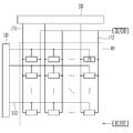
도 1은 일 실시예에 따른 유기 발광 표시 장치의 블록도이다.1 is a block diagram of an organic light emitting diode display according to an exemplary embodiment.
도 1을 참고하면, 일 실시예에 따른 유기 발광 표시 장치는 게이트 구동부(GD), 데이터 구동부(DD), 및 화소부(40)를 포함할 수 있다. 화소부(40)는 복수의 화소(PX)를 포함한다. 화소(PX)는 이미지(iamge)을 표시하는 최소 단위를 말하며, 유기 발광 표시 장치는 복수의 화소(PX)를 통해 이미지를 표시한다.Referring to FIG. 1, an organic light emitting diode display according to an exemplary embodiment may include a gate driver GD, a data driver DD, and a
게이트 구동부(GD)는 외부로부터 공급되는 구동 전원 및 제어 신호들에 대응하여 스캔 신호를 생성하고, 이를 게이트선(152)으로 공급한다. 화소들(PX)은 스캔 신호에 의해 선택되어 순차적으로 데이터 전압를 공급받는다.The gate driver GD generates a scan signal in response to driving power and control signals supplied from the outside, and supplies the scan signal to the
게이트 구동부(GD)는 화소부(40)에 포함되는 화소 회로와 함께 기판 위에 박막 트랜지스터의 형태로 구비되거나, 칩의 형태로 기판 위에 실장될 수 있다. 게이트 구동부(GD)의 위치는 도시한 예로 한정되지 않는다. The gate driver GD may be provided in the form of a thin film transistor on the substrate together with the pixel circuit included in the
데이터 구동부(DD)는 외부로부터 공급되는 데이터 및 제어 신호들에 대응하여 데이터 전압을 생성하고, 이를 데이터선(171)으로 공급한다. 데이터선(171)으로 공급된 데이터 전압은 스캔 신호가 공급될 때마다 스캔 신호에 의해 선택된 화소(PX)로 공급된다. 실시예에 따라서는 유기 발광 표시 장치는 발광 제어 신호를 공급하는 발광 제어 구동부(미도시)를 더 포함할 수도 있다.The data driver DD generates a data voltage in response to data and control signals supplied from the outside, and supplies it to the
화소부(40)는 게이트선(152)과 데이터선(171)의 교차부에 위치하는 복수의 화소(PX)를 포함한다. 화소부(40)는 외부로부터 고전위 화소 전원인 구동 전압(ELVDD)과 저전위 화소 전원인 공통 전압(ELVSS)을 공급받고, 구동 전압(ELVDD)과 공통 전압(ELVSS)은 각 화소(PX)로 전달된다.The
화소(PX)는 데이터 전압에 대응하여 구동 전압(ELVDD)으로부터 공통 전압 (ELVSS)으로 흐르는 구동 전류에 상응하는 휘도로 발광하여 영상을 표시한다.The pixel PX displays an image by emitting light with luminance corresponding to a driving current flowing from the driving voltage ELVDD to the common voltage ELVSS in response to the data voltage.
이하, 도 2와 도 3을 참고하여 일 실시예에 따른 유기 발광 표시 장치에 대해 설명한다. Hereinafter, an organic light emitting display device according to an exemplary embodiment will be described with reference to FIGS. 2 and 3.
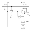
도 2는 본 발명의 일 실시예에 따른 유기 발광 표시 장치의 한 화소의 등가 회로도이다.2 is an equivalent circuit diagram of one pixel of an organic light emitting diode display according to an exemplary embodiment of the present invention.
도 2를 참조하면, 본 발명의 일 실시예에 따른 유기 발광 표시 장치는 복수개의 신호선(152, 171, 172), 복수개의 트랜지스터(T1, T2), 유지 축전기(Cst), 그리고 유기 발광 소자(OLED)를 포함한다. 또한, 본 실시예에 따른 유기 발광 표시 장치는 구동 트랜지스터(T2)와 평면상 중첩하도록 위치하는 차단층(160)을 더 포함한다. Referring to FIG. 2, an organic light emitting display device according to an exemplary embodiment of the present invention includes a plurality of
신호선(152, 171, 172)은 스캔 신호(Sn)를 전달하는 게이트선(152), 데이터 전압(Dm)를 전달하는 데이터선(171) 및 구동 전압(ELVDD)을 전달하는 구동 전압선(172)을 포함한다. The signal lines 152, 171, and 172 are
트랜지스터(T1, T2)는 스위칭 트랜지스터(T1)와 구동 트랜지스터(T2)를 포함한다. The transistors T1 and T2 include a switching transistor T1 and a driving transistor T2.
스위칭 트랜지스터(T1)는 게이트선(152)과 연결되는 게이트 전극, 데이터선(171)과 연결되는 제1 전극 및 구동 트랜지스터(T2)의 게이트 전극과 연결되는 제2 전극을 포함한다. 스위칭 트랜지스터(T1)의 제2 전극은 유지 축전기(Cst)의 제1 유지 전극과도 연결되어 있다. 스위칭 트랜지스터(T1)는 게이트선(152)에 연결되어 스캔 신호(Sn)에 응답하여 턴 온 되며, 스위칭 트랜지스터(T1)가 턴 온 되는 경우, 데이터선(171)을 통해 공급되는 데이터 전압(Dm)이 제1 유지 축전기(Cst)의 제1 유지 전극에 공급된다.The switching transistor T1 includes a gate electrode connected to the
구동 트랜지스터(T2)는 유지 축전기(Cst)의 제1 유지 전극과 연결되는 게이트 전극, 구동 전압(ELVDD)을 인가 받는 제1 전극 및 유기 발광 소자(OLED)의 제1 전극과 연결되는 제2 전극을 포함할 수 있다. 구동 트랜지스터(T2)의 제1 전극은 차단층(160)과도 연결되어 있으며, 구동 트랜지스터(T2)의 제2 전극은 유지 축전기(Cst)의 제2 유지 전극과도 연결되어 있다. 구동 트랜지스터(T2)는 유지 축전기(Cst)에 저장된 데이터 전압에 따라 구동 전류를 유기 발광 소자(OLED)로 출력한다.The driving transistor T2 includes a gate electrode connected to the first storage electrode of the storage capacitor Cst, a first electrode receiving a driving voltage ELVDD, and a second electrode connected to the first electrode of the organic light emitting diode OLED. It may include. The first electrode of the driving transistor T2 is also connected to the
유지 축전기(Cst)는 제1 유지 전극과 제2 유지 전극을 포함한다. 유지 축전기(Cst)의 제1 유지 전극은 스위칭 트랜지스터(T1)의 제2 전극 및 구동 트랜지스터(T2)의 게이트 전극과 연결된다. 유지 축전기(Cst)의 제2 유지 전극은 구동 트랜지스터(T2)의 제2 전극과 연결된다. 또한, 유지 축전기(Cst)의 제2 유지 전극은 유기 발광 소자(OLED)의 제1 전극과도 연결된다. 유지 축전기(Cst)는 스위칭 트랜지스터(T1)를 통해서 공급되는 데이터 전압(Dm)을 저장할 수 있다. 유지 축전기(Cst)에 저장된 데이터 전압(Dm)은 구동 트랜지스터(T2)가 턴 온 되는 정도를 조절하여 구동 전류의 크기를 정한다. 한편, 도 2에서는 두 개의 트랜지스터와 한 개의 커패시터를 포함하는 구조를 도시하고 있지만, 본 발명이 이에 한정되는 것은 아니며 추가적으로 트랜지스터 또는 커패시터를 더 포함할 수 있다.The storage capacitor Cst includes a first storage electrode and a second storage electrode. The first storage electrode of the storage capacitor Cst is connected to the second electrode of the switching transistor T1 and the gate electrode of the driving transistor T2. The second storage electrode of the storage capacitor Cst is connected to the second electrode of the driving transistor T2. Further, the second storage electrode of the storage capacitor Cst is also connected to the first electrode of the organic light emitting diode OLED. The storage capacitor Cst may store the data voltage Dm supplied through the switching transistor T1. The data voltage Dm stored in the storage capacitor Cst controls the degree to which the driving transistor T2 is turned on to determine the magnitude of the driving current. Meanwhile, although FIG. 2 shows a structure including two transistors and one capacitor, the present invention is not limited thereto, and may further include a transistor or a capacitor.
유기 발광 소자(OLED)는 구동 트랜지스터(T2)의 제2 전극과 연결되는 제1 전극 및 공통 전압(ELVSS)이 인가되는 제2 전극를 포함한다. 유기 발광 소자(OLED)의 제1 전극은 애노드(anode)이고, 유기 발광 소자(OLED)의 제2 전극은 캐소드(cathode)일 수 있다. 유기 발광 소자(OLED)는 구동 트랜지스터(T2)로부터 출력되는 구동 전류에 따라 발광하여 그 밝은 정도에 따라서 계조를 표현한다. The organic light emitting diode OLED includes a first electrode connected to the second electrode of the driving transistor T2 and a second electrode to which the common voltage ELVSS is applied. The first electrode of the organic light emitting diode (OLED) may be an anode, and the second electrode of the organic light emitting diode (OLED) may be a cathode. The organic light emitting diode OLED emits light according to the driving current output from the driving transistor T2 and expresses gradation according to its brightness.
차단층(160)은 구동 전압(ELVDD)이 전달되는 구동 전압선(172)과 전기적으로 연결된다. 차단층(160)은 도전 특성을 가지는 금속이나 이에 준하는 도전 특성을 가지는 반도체 물질로 형성될 수 있다. 차단층(160)에는 구동 전압(ELVDD)이 일정하게 인가되어 차단층(160)에 특정 전하가 주입되면서 전위가 변하는 것을 방지할 수 있다. 차단층(160)은 회로도상 구동 트랜지스터(T2)의 제2 게이트 전극과 같은 역할 한다. 다만, 차단층(160)에는 일정 전압이 인가되므로 구동 트랜지스터(T2)를 턴 온 시키거나 하지 않고, 구동 트랜지스터(T2)가 일정한 특성을 가지도록 한다.The
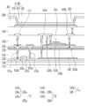
도 3은 일 실시예에 따른 유기 발광 표시 장치의 단면도이다. 3 is a cross-sectional view of an organic light emitting diode display according to an exemplary embodiment.
도 3을 참조하면, 본 실시예에 따른 유기 발광 표시 장치는 기판(110), 스위칭 트랜지스터(T1), 구동 트랜지스터(T2), 및 유기 발광 소자(OLED)를 포함한다. Referring to FIG. 3, the organic light emitting diode display according to the present exemplary embodiment includes a
기판(110)은 잘 휘어지고 구부러지며 접히거나 말릴 수 있는 플라스틱 등의 플렉서블 소재를 포함할 수 있다. 예컨대, 기판(110)은 폴리이미드(polyimide), 폴리아미드(polyamide), 폴리카보네이트(polycarbonate), 폴리에틸렌 테레프탈레이드(polyethylene terephthalate) 같은 폴리머로 이루어질 수 있다. 기판(110)은 유리 같은 재료로 이루어진 리지드(rigid) 기판일 수도 있다.The
기판(110) 위에는 제1 버퍼층(121)이 위치한다. 제1 버퍼층(121)은 실리콘질화물(SiNx) 또는 실리콘산화물(SiOx) 등을 포함할 수 있다. 제1 버퍼층(121)은 기판(110)과 제1 반도체층(136a) 사이에 위치하여, 기판(110)으로부터 제1 반도체층(136a)으로 확산될 수 있는 불순물을 차단하고, 기판(110)을 평탄화시켜 제1 버퍼층(121) 위에 형성되는 제1 반도체층(136a)의 스트레스를 완화할 수 있다. The
제1 버퍼층(121) 위에는 제1 반도체층(136a)이 위치한다. 제1 반도체층(136a)은 다결정 규소로 이루어질 수 있다. The
제1 반도체층(136a)은 비정질 규소(amorphous silicon)를 엑시머 레이저 어닐링(excimer layer annealing, ELA) 같은 결정화 방법에 의해 결정화하여 형성된 다결정 규소로 이루어질 수 있으며, 제1 채널 영역(134a), 제1 소스 영역(133a) 및 제1 드레인 영역(135a)을 포함한다. 제1 소스 영역(133a) 및 제1 드레인 영역(135a)은 각각 제1 채널 영역(134a)의 양 옆에 배치되어 있다. 제1 채널 영역(134a)은 불순물이 도핑되지 않은 진성 반도체(intrinsic semiconductor)이고, 제1 소스 영역(133a) 및 제1 드레인 영역(135a)은 도전성 불순물이 도핑되어 있는 불순물 반도체(impurity semiconductor)이다. 도전성 불순물은 P형 불순물일 수 있다. The
제1 반도체층(136a) 위에는 제1 게이트 절연막(122)이 위치한다. 제1 게이트 절연막(122)은 실리콘질화물(SiNx) 및 실리콘산화물(SiOx) 중 적어도 하나를 포함한 단층 또는 다층일 수 있다.The first
제1 게이트 절연막(122) 위에는 제1 게이트 전극(155a)과 차단층(160)이 위치한다. The
제1 게이트 전극(155a)은 구리(Cu), 구리 합금, 알루미늄(Al), 알루미늄 합금, 몰리브덴(Mo), 및 몰리브덴 합금 중 어느 하나를 포함하는 금속막이 적층된 다중막일 수 있다. 제1 게이트 전극(155a)과 제1 반도체층(136a)은 스위칭 트랜지스터(T1)를 구성할 수 있다.The
차단층(160)은 제1 게이트 전극(155a)과 동일한 층에 위치한다. 차단층(160)은 제1 게이트 전극(155a)과 동일한 층에 함께 형성되어 추가 마스크 공정 없이 차단층(160)을 형성할 수 있으므로, 공정이 간소화될 수 있다. 차단층(160)은 오프닝을 통해 구동 전압선(172)과 전기적으로 연결되어 구동 전압(ELVDD)을 인가 받는다. 차단층(160)은 도전 특성을 가지는 금속이나 이에 준하는 도전 특성을 가지는 반도체 물질로 형성될 수 있다.The
제1 게이트 전극(155a), 차단층(160) 및 제1 게이트 절연막(122) 위에는 제2 버퍼층(141)이 위치한다. 제2 버퍼층(141)은 실리콘질화물(SiNx) 또는 실리콘산화물(SiOx) 등을 포함할 수 있다. 제2 버퍼층(141)에는 제1 소스 영역(133a) 및 제1 드레인 영역(135a)을 각각 노출하는 오프닝이 위치한다. The
제2 버퍼층(141) 위에 제2 반도체층(136b)이 위치한다. 제2 반도체층(136b)은 제2 채널 영역(134b), 제2 소스 영역(133b) 및 제2 드레인 영역(135b)을 포함한다. 제2 소스 영역(133b) 및 제2 드레인 영역(135b)은 각각 제2 채널 영역(134b)의 양 옆에 배치되어 있다. The
제2 반도체층(136b)은 산화물 반도체로 이루어질 수 있다. 제1 반도체층(136a)이 다결정 규소로 이루어지고 제2 반도체층(136b)이 산화물 반도체인 것으로 설명하였지만, 스위칭 트랜지스터(T1)의 제1 반도체층(136a)이 다결정 규소에 비해 오프 전류 특성이 좋은 산화물 반도체로 형성되고, 구동 트랜지스터(T2)의 제2 반도체층(136b)이 다결정 규소로 형성될 수도 있다. The
그러나 이에 제한되지 않고, 제1 반도체층(136a)과 제2 반도체층(136b)이 모두 다결정 규소로 이루어지거나, 제1 반도체층(136a)과 제2 반도체층(136b)이 모두 산화물 반도체로 이루어지는 것도 가능하다. However, the present invention is not limited thereto, and both the
제2 반도체층(136b) 위에 제2 게이트 절연막(123)이 위치한다. 제2 게이트 절연막(123)은 실리콘질화물(SiNx) 및 실리콘산화물(SiOx) 중 적어도 하나를 포함한 단층 또는 다층일 수 있다. The second
제2 게이트 절연막(123) 위에 제1 소스 전극(161a)과 제1 드레인 전극(162a)이 위치한다. 제1 소스 전극(161a)과 제1 드레인 전극(162a)은 제1 게이트 절연막(122), 제2 버퍼층(141), 및 제2 게이트 절연막(123)에 형성된 오프닝을 통해 제1 반도체층(136a)의 제1 소스 영역(133a) 및 제1 드레인 영역(135a)과 각각 연결된다. The
제2 게이트 절연막(123) 위에는 제2 채널 영역(134b)과 중첩하는 제2 게이트 전극(155b) 또한 위치한다. 제2 게이트 전극(155b)은 구리(Cu), 구리 합금, 알루미늄(Al), 알루미늄 합금, 몰리브덴(Mo), 및 몰리브덴 합금 중 어느 하나를 포함하는 금속막이 적층된 다중막일 수 있다. 제2 게이트 전극(155b), 제2 반도체층(136b)은 구동 트랜지스터(T2)를 구성할 수 있다.The
본 실시예에 따른 유기 발광 표시 장치에서는 스위칭 트랜지스터(T1)와 구동 트랜지스터(T2)가 다른 층에 위치한다. 다시 말해, 스위칭 트랜지스터(T1)의 제1 반도체층(136a)과 구동 트랜지스터(T2)의 제2 반도체층(136b)은 다른 층에 위치한다. 따라서, 스위칭 트랜지스터(T1)와 구동 트랜지스터(T2)의 간격을 좁히거나 부분적으로 중첩하게 배치하는 것이 가능하여, 설계 자유도가 증가한다. 또한, 화소의 개구율을 증가시키거나, 표시 장치의 해상도를 증가시키는데 유리하다. In the organic light emitting diode display according to the exemplary embodiment, the switching transistor T1 and the driving transistor T2 are located on different layers. In other words, the
이 때, 차단층(160)은 구동 트랜지스터(T2)의 제2 채널 영역(134b)과 중첩하는 영역에 위치한다. 차단층(160)은 제2 채널 영역(134b)의 양 옆에 위치하는 제2 소스 영역(133b) 및 제2 드레인 영역(135b)과도 중첩할 수 있다. 또한, 차단층(160)은 스위칭 트랜지스터(T1)의 제1 채널 영역(134a)과는 중첩하지 않을 수 있다. 구동 트랜지스터(T2)의 하부에 차단층(160)이 위치하여, 스위칭 트랜지스터(T1)와 구동 트랜지스터(T2)의 기생 용량에 의한 킥백 전압을 최소화할 수 있고, 후술하는 바와 같이, 잔상이 남지 않도록 하여 유기 발광 표시 장치의 표시 품질이 향상될 수 있다. 또한, 제2 반도체층(136b)의 아래에 위치하는 차단층(160)은 플로팅 되지 않고 구동 전압(ELVDD)을 인가 받으므로 불필요한 기생 용량으로 인한 표시 품질의 저하를 방지할 수 있다.At this time, the
제2 게이트 절연막(123), 제1 소스 전극(161a), 제1 드레인 전극(162a) 및 제2 게이트 전극(155b) 위에는 제3 게이트 절연막(124)이 위치하고, 제3 게이트 절연막(124) 위에는 제2 드레인 전극(162b)과 제2 드레인 전극(162b)에서 연장되어 형성된 제2 유지 전극(165)이 위치한다. The third
제2 드레인 전극(162b)은 제2 게이트 절연막(123)과 제3 게이트 절연막(124)에 형성된 오프닝을 통해 구동 트랜지스터(T2)의 제2 드레인 영역(135b)과 연결된다. 제2 유지 전극(165)은 제2 드레인 전극(162b)로부터 연장되어 제2 게이트 전극(155b)과 중첩한다. 제2 게이트 전극(155b)과 제2 유지 전극(165)은 제3 게이트 절연막(124)를 사이에 두고 중첩하여 유지 축전기(Cst)를 구성한다. 이 때, 제2 게이트 전극(155b)은 유지 축전기(Cst)의 제1 유지 전극일 수 있다. 제3 게이트 절연막(124)은 유전체가 되며, 유지 축전기(Cst)에서 축전된 전하와 제1 유지 전극(155b) 및 제2 유지 전극(165) 사이의 전압에 의해 스토리지 커패시턴스(Storage Capacitance)가 결정된다.The
제3 게이트 절연막(124)과 제2 유지 전극(165) 위에 층간 절연막(142)이 위치한다. 층간 절연막(142)은 실리콘질화물(SiNx) 및 실리콘산화물(SiOx) 중 적어도 하나를 포함한 단층 또는 다층일 수 있다. The interlayer insulating
층간 절연막(142) 위에 제2 소스 전극(161b)과 연결 부재(174)가 위치한다. 제2 소스 전극(161b)은 층간 절연막(142)과 제2 게이트 절연막(123) 및 제3 게이트 절연막(124)에 형성된 오프닝을 통해 제2 반도체층(136b)의 제2 소스 영역(133b)과 연결된다. 연결 부재(174)는 층간 절연막(142)에 형성된 오프닝을 통해 구동 트랜지스터(T2)의 제2 드레인 전극(162b) 및 유치 축전기(Cst)의 제2 유지 전극(165)과 연결된다.The
제2 소스 전극(161b)은 연장되어 구동 전압선(172)과 연결되어 구동 전압(ELVDD)을 인가받고, 제2 버퍼층(141)과 층간 절연막(142)에 형성된 오프닝을 통해 차단층(160)과도 연결된다. 이에 따라, 차단층(160)은 플로팅 되지 않고, 구동 전압(ELVDD)을 인가 받는다. The
층간 절연막(142) 위에는 데이터선(171)도 위치한다. 데이터선(171)은 층간 절연막(142)에 위치하는 오프닝을 통해 스위칭 트랜지스터(T1)의 제1 소스 전극(161a)과 연결되어 스위칭 트랜지스터(T1)에 데이터 전압을 전달한다. The
층간 절연막(142), 데이터선(171), 제2 소스 전극(161b) 및 제2 드레인 전극(162b) 위에는 보호막(180)이 위치한다. 보호막(180)은 층간 절연막(142), 제2 소스 전극(161b) 및 제2 드레인 전극(162b)을 덮어 평탄화시키므로 보호막(180) 위에 화소 전극(191)을 단차 없이 형성할 수 있다. 이러한 보호막(180)은 폴리아크릴계 수지(polyacrylates resin), 폴리이미드계 수지(polyimides resin) 등의 유기물 또는 유기물과 무기물의 적층막 등으로 만들어질 수 있다.The
보호막(180) 위에는 화소 전극(191)이 위치한다. 화소 전극(191)은 보호막(180)에 형성된 오프닝을 통해 연결 부재(174)와 연결된다. 따라서, 화소 전극(191)은 연결 부재(174)를 통해 구동 트랜지스터(T2)의 제2 드레인 전극(162b)과 연결되어 있다. 구동 트랜지스터(T2)는 화소 전극(191)에 연결되어 유기 발광 소자에 구동 전류를 공급한다. The
보호막(180)과 화소 전극(191)의 위에는 이를 덮는 격벽(361)이 위치하고, 격벽(361)은 화소 전극(191)을 드러내는 화소 개구부(365)를 가진다. 격벽(361)은 폴리아크릴계 수지(polyacrylates resin), 폴리이미드계 수지(polyimides resin) 등의 유기물 또는 실리카 계열의 무기물을 포함할 수 있다. On the
화소 개구부(365)에 의해 노출된 화소 전극(191) 위에는 유기 발광층(370)이 위치한다. 유기 발광층(370)은 저분자 유기물 또는 PEDOT(Poly 3,4-ethylenedioxythiophene) 등의 고분자 유기물로 이루어질 수 있다. 또한, 유기 발광층(370)은 정공 주입층(hole injection layer, HIL), 정공 수송층(hole transporting layer, HTL), 전자 수송층(electron transporting layer, ETL), 및 전자 주입층(electron injection layer, EIL) 중 하나 이상을 더 포함하는 다중막일 수 있다. The
유기 발광층(370)은 적색광을 방출하는 적색 유기 발광층, 녹색광을 방출하는 녹색 유기 발광층 및 청색광을 방출하는 청색 유기 발광층을 포함할 수 있다. The
유기 발광층(370) 위에는 공통 전극(270)이 위치한다. 공통 전극(270)은 복수의 화소에 걸쳐 위치할 수 있다. 화소 전극(191), 유기 발광층(370)과 공통 전극(270)은 유기 발광 소자(OLED)를 구성할 수 있다. The
여기서, 화소 전극(191)은 정공 주입 전극인 애노드이며, 공통 전극(270)은 전자 주입 전극인 캐소드 일 수 있다. 그러나 본 발명에 따른 일 실시예는 반드시 이에 한정되는 것은 아니며, 유기 발광 표시장치의 구동 방법에 따라 화소 전극(191)이 캐소드가 되고, 공통 전극(270)이 애노드가 될 수도 있다. 화소 전극(191) 및 공통 전극(270)으로부터 각각 정공과 전자가 유기 발광층(370) 내부로 주입되고, 주입된 정공과 전자가 결합한 엑시톤(exiton)이 여기상태로부터 기저상태로 떨어질 때 발광이 이루어진다.Here, the
공통 전극(270) 위에 봉지층(390)이 위치한다. 유기 발광 소자(OLED)는 수분과 산소에 매우 취약하므로, 봉지층(390)이 유기 발광 소자(OLED)를 밀봉하여 외부의 수분 및 산소의 유입을 차단한다. 봉지층(390)은 복수의 층을 포함할 수 있고, 그 중 무기막과 유기막을 모두 포함하는 복합막으로 형성될 수 있으며, 무기막, 유기막, 무기막이 순차적으로 형성된 3중층으로 형성될 수 있다. The
도 4는 비교예와 일 실시예에 따른 유기 발광 표시 장치의 순간 잔상 지속 시간을 나타내는 그래프이다. 도 4에서 A는 차단층을 포함하지 않는 비교예에 따른 유기 발광 표시 장치를 나타내고, B는 본 발명의 일 실시예에 따라 구동 트랜지스터의 채널 영역과 중첩하는 차단층을 포함하는 유기 발광 표시 장치를 나타낸다.FIG. 4 is a graph showing an instantaneous afterimage duration of an organic light emitting diode display according to a comparative example and an embodiment. In FIG. 4, A denotes an organic light emitting display device according to a comparative example not including a blocking layer, and B denotes an organic light emitting display device including a blocking layer overlapping a channel region of a driving transistor according to an embodiment of the present invention. Shows.
유기 발광 표시 장치에서 10초간 블랙과 화이트를 표시한 후 동시에 저계조의 회색을 구동하면 동일한 색상을 구동함에도 불구하고 블랙을 표시하던 영역과 화이트를 표시하던 영역에서 휘도차가 발생한다. 구체적으로, 블랙을 표시하던 영역은 저계조의 회색 구동 직후에 구동하고자 하는 회색에 비해 더 밝게 보이고, 화이트를 표시하던 영역은 구동하고자 하는 회색에 비해 더 어둡게 보인다. 순간 잔상은 이러한 휘도차에 의해 시인되는 잔상을 의미한다. When the black and white are displayed for 10 seconds in the organic light emitting display and simultaneously driving low gray level, a luminance difference occurs in a region displaying black and a region displaying white despite driving the same color. Specifically, the area displaying black appears brighter than the gray to be driven immediately after the gray driving of the low gray level, and the area displaying white appears darker than the gray to be driven. The instantaneous afterimage means an afterimage recognized by this luminance difference.
도 4의 순간 잔상의 지속 시간은 저계조 회색 구동 직후부터 블랙을 표시하던 영역과 화이트를 표시하던 영역의 휘도차가 0.4 %에 도달하기 까지 걸리는 시간을 측정한 결과이다. 여기에서, 휘도차는 (B-W)/(B+W)로 계산되며, B는 블랙을 표시하던 영역의 휘도를, W는 화이트를 표시하던 영역의 휘도를 의미한다. 순간 잔상은 표시 장치의 표시 품질과도 직결되는 문제로 순간 잔상의 지속 시간이 줄어들면 더 선명한 이미지 구현이 가능하다. 이러한, 순간 잔상은 유기 발광 표시 장치 내의 트랜지스터 간에 발생하는 수직 크로스톡을 최소화하여 개선할 수 있다. The duration of the instantaneous afterimage in FIG. 4 is a result of measuring the time it takes for the luminance difference between the black-displayed area and the white-displayed area to reach 0.4% immediately after the low grayscale driving. Here, the luminance difference is calculated as (B-W) / (B + W), where B represents the luminance of the region displaying black and W represents the luminance of the region displaying white. The instantaneous afterimage is a problem directly related to the display quality of the display device. If the duration of the instantaneous afterimage is reduced, a clearer image can be realized. The instantaneous afterimage can be improved by minimizing vertical crosstalk occurring between transistors in the organic light emitting diode display.
도 4를 참조하면, A의 경우, 순간 잔상은 7.66151초 지속되었다. 그러나, B의 경우에는 순간 잔상이 4.42379초 지속되는 것을 확인할 수 있었다. 따라서, 차단층을 포함하는 유기 발광 표시 장치는 차단층을 포함하지 않는 유기 발광 표시 장치(비교예)에 비해 약 3.2초만큼 순간 잔상이 개선됨을 알 수 있다. Referring to FIG. 4, in the case of A, the instantaneous afterimage lasted 7.66151 seconds. However, in the case of B, it was confirmed that the instantaneous afterimage lasted 4.42379 seconds. Therefore, it can be seen that the organic light emitting display device including the blocking layer improves the instantaneous afterimage by about 3.2 seconds compared to the organic light emitting display device without the blocking layer (comparative example).
이하, 도 5와 도 6을 참조하여 본 발명의 다른 일 실시예에 따른 유기 발광 표시 장치에 대해 설명한다. Hereinafter, an organic light emitting display device according to another exemplary embodiment of the present invention will be described with reference to FIGS. 5 and 6.
도 5는 다른 일 실시예에 따른 유기 발광 표시 장치의 한 화소의 등가 회로도이다. 5 is an equivalent circuit diagram of one pixel of an organic light emitting diode display according to another exemplary embodiment.
도 5를 참조하면, 본 발명의 일 실시예에 따른 유기 발광 표시 장치는 복수개의 신호선(152, 171, 172), 복수개의 트랜지스터(T1, T2), 유지 축전기(Cst), 그리고 유기 발광 소자(OLED)를 포함한다. 또한, 본 실시예에 따른 유기 발광 표시 장치는 구동 트랜지스터(T2)와 평면상 중첩하도록 위치하는 차단층(160)을 더 포함한다. 유지 축전기(Cst)의 제2 유지 전극이 구동 전압선(172) 및 구동 트랜지스터(T2)의 제1 전극에 연결되는 것을 제외하면 도 2와 유사하므로, 중복되는 내용의 설명은 생략한다.Referring to FIG. 5, an organic light emitting display device according to an exemplary embodiment of the present invention includes a plurality of
유지 축전기(Cst)는 제1 유지 전극과 제2 유지 전극을 포함한다. 유지 축전기(Cst)의 제1 유지 전극은 스위칭 트랜지스터(T1)의 제2 전극 및 구동 트랜지스터(T2)의 게이트 전극과 연결된다. 유지 축전기(Cst)의 제2 유지 전극은 구동 전압선(172)과 연결된다. 또한, 유지 축전기(Cst)의 제2 유지 전극은 구동 트랜지스터(T2)의 제1 전극과 차단층(160)과도 연결된다. The storage capacitor Cst includes a first storage electrode and a second storage electrode. The first storage electrode of the storage capacitor Cst is connected to the second electrode of the switching transistor T1 and the gate electrode of the driving transistor T2. The second storage electrode of the storage capacitor Cst is connected to the driving
유지 축전기(Cst)는 스위칭 트랜지스터(T1)를 통해서 공급되는 데이터 전압(Dm)을 저장할 수 있다. 유지 축전기(Cst)에 저장된 데이터 전압(Dm)은 구동 트랜지스터(T2)가 턴 온 되는 정도를 조절하여 구동 전류의 크기를 정한다. The storage capacitor Cst may store the data voltage Dm supplied through the switching transistor T1. The data voltage Dm stored in the storage capacitor Cst controls the degree to which the driving transistor T2 is turned on to determine the magnitude of the driving current.
차단층(160)은 구동 전압(ELVDD)이 전달되는 구동 전압선(172)과 전기적으로 연결된다. 차단층(160)은 도전 특성을 가지는 금속이나 이에 준하는 도전 특성을 가지는 반도체 물질로 형성될 수 있다. 차단층(160)에는 구동 전압(ELVDD)이 일정하게 인가되어 차단층(160)에 특정 전하가 주입되면서 전위가 변하는 것을 방지할 수 있다. 차단층(160)은 회로도상 구동 트랜지스터(T2)의 제2 게이트 전극과 같은 역할 한다. 다만, 차단층(160)에는 일정 전압이 인가되므로 구동 트랜지스터(T2)를 턴 온 시키거나 하지 않고, 구동 트랜지스터(T2)가 일정한 특성을 가지도록 한다.The
도 6은 다른 일 실시예에 따른 유기 발광 표시 장치의 단면도이다. 도 6의 구성은 도 3과 유사하므로, 도 3과 중복되는 내용의 구체적인 설명은 생략한다. 6 is a cross-sectional view of an organic light emitting diode display according to another exemplary embodiment. Since the configuration of FIG. 6 is similar to that of FIG. 3, detailed description of the content overlapping with FIG. 3 will be omitted.
도 6을 참조하면, 본 실시예에 따른 유기 발광 표시 장치는 기판(110), 스위칭 트랜지스터(T1), 구동 트랜지스터(T2), 및 유기 발광 소자(OLED)를 포함한다. Referring to FIG. 6, the organic light emitting diode display according to the present exemplary embodiment includes a
기판(110)은 플렉서블 소재를 포함하거나, 기판(110)은 유리 같은 재료로 이루어진 리지드(rigid) 기판일 수도 있다.The
기판(110) 위에는 제1 버퍼층(121)이 위치하고, 제1 버퍼층(121) 위에는 제1 반도체층(136a)이 위치한다. 제1 반도체층(136a)은 다결정 규소로 이루어질 수 있고, 제1 채널 영역(134a), 제1 소스 영역(133a) 및 제1 드레인 영역(135a)을 포함한다. 제1 소스 영역(133a) 및 제1 드레인 영역(135a)은 각각 제1 채널 영역(134a)의 양 옆에 배치되어 있다. 제1 채널 영역(134a)은 불순물이 도핑되지 않은 진성 반도체(intrinsic semiconductor)이고, 제1 소스 영역(133a) 및 제1 드레인 영역(135a)은 도전성 불순물이 도핑되어 있는 불순물 반도체(impurity semiconductor)이다. 도전성 불순물은 P형 불순물일 수 있다. The
제1 반도체층(136a) 위에는 제1 게이트 절연막(122)이 위치한다. 제1 게이트 절연막(122)은 실리콘질화물(SiNx) 및 실리콘산화물(SiOx) 중 적어도 하나를 포함한 단층 또는 다층일 수 있다.The first
제1 게이트 절연막(122) 위에는 제1 게이트 전극(155a)과 차단층(160)이 위치한다. 제1 게이트 전극(155a)과 제1 반도체층(136a)은 스위칭 트랜지스터(T1)를 구성할 수 있다.The
차단층(160)은 제1 게이트 전극(155a)과 동일한 층에 위치한다. 차단층(160)은 제1 게이트 전극(155a)과 동일한 층에 함께 형성되어 추가 마스크 공정 없이 차단층(160)을 형성할 수 있으므로, 공정이 간소화될 수 있다. 차단층(160)은 오프닝을 통해 구동 전압선(172)과 전기적으로 연결되어 구동 전압(ELVDD)을 인가 받는다. 차단층(160)은 도전 특성을 가지는 금속이나 이에 준하는 도전 특성을 가지는 반도체 물질로 형성될 수 있다.The
제1 게이트 전극(155a), 차단층(160) 및 제1 게이트 절연막(122) 위에는 제2 버퍼층(141)이 위치한다. 제2 버퍼층(141)에는 제1 소스 영역(133a) 및 제1 드레인 영역(135a)을 각각 노출하는 오프닝이 위치한다. The
제2 버퍼층(141) 위에 제2 반도체층(136b)이 위치한다. 제2 반도체층(136b)은 제2 채널 영역(134b), 제2 소스 영역(133b) 및 제2 드레인 영역(135b)을 포함한다. 제2 소스 영역(133b) 및 제2 드레인 영역(135b)은 각각 제2 채널 영역(134b)의 양 옆에 배치되어 있다. 제2 반도체층(136b)은 산화물 반도체로 이루어질 수 있다. The
또는, 스위칭 트랜지스터(T1)의 제1 반도체층(136a)이 다결정 규소에 비해 오프 전류 특성이 좋은 산화물 반도체로 형성되고, 구동 트랜지스터(T2)의 제2 반도체층(136b)이 다결정 규소로 형성될 수도 있다. 그러나 이에 제한되지 않고, 제1 반도체층(136a)과 제2 반도체층(136b)이 모두 다결정 규소로 이루어지거나, 제1 반도체층(136a)과 제2 반도체층(136b)이 모두 산화물 반도체로 이루어지는 것도 가능하다. Alternatively, the
제2 반도체층(136b) 위에 제2 게이트 절연막(123)이 위치하고, 제2 게이트 절연막(123) 위에 제1 소스 전극(161a)과 제1 드레인 전극(162a)이 위치한다. 제1 소스 전극(161a)과 제1 드레인 전극(162a)은 제1 게이트 절연막(122), 제2 버퍼층(141), 및 제2 게이트 절연막(123)에 형성된 오프닝을 통해 제1 반도체층(136a)의 제1 소스 영역(133a) 및 제1 드레인 영역(135a)과 각각 연결된다. The second
제2 게이트 절연막(123) 위에는 제2 채널 영역(134b)과 중첩하는 제2 게이트 전극(155b) 또한 위치한다. 제2 게이트 전극(155b)과 제2 반도체층(136b)은 구동 트랜지스터(T2)를 구성할 수 있다.The
본 실시예에 따른 유기 발광 표시 장치에서는 스위칭 트랜지스터(T1)와 구동 트랜지스터(T2)가 다른 층에 위치한다. 다시 말해, 스위칭 트랜지스터(T1)의 제1 반도체층(136a)과 구동 트랜지스터(T2)의 제2 반도체층(136b)은 다른 층에 위치한다. 따라서, 스위칭 트랜지스터(T1)와 구동 트랜지스터(T2)의 간격을 좁히거나 부분적으로 중첩하게 배치하는 것이 가능하여, 설계 자유도가 증가한다. 또한, 화소의 개구율을 증가시키거나, 표시 장치의 해상도를 증가시키는데 유리하다. In the organic light emitting diode display according to the exemplary embodiment, the switching transistor T1 and the driving transistor T2 are located on different layers. In other words, the
이 때, 차단층(160)은 구동 트랜지스터(T2)의 제2 채널 영역(134b)과 중첩하는 영역에 위치한다. 차단층(160)은 제2 채널 영역(134b)의 양 옆에 위치하는 제2 소스 영역(133b) 및 제2 드레인 영역(135b)과도 중첩할 수 있다. 또한, 차단층(160)은 스위칭 트랜지스터(T1)의 제1 채널 영역(134a)과는 중첩하지 않을 수 있다. 구동 트랜지스터(T2)의 하부에 차단층(160)이 위치하여, 스위칭 트랜지스터(T1)와 구동 트랜지스터(T2)의 기생 용량에 의한 킥백 전압을 최소화할 수 있고, 후술하는 바와 같이, 잔상이 남지 않도록 하여 유기 발광 표시 장치의 표시 품질이 향상될 수 있다. 덧붙여, 제2 반도체층(136b)의 아래에 위치하는 차단층(160)은 플로팅 되지 않고 구동 전압(ELVDD)을 인가 받으므로 불필요한 기생 용량으로 인한 표시 품질의 저하를 방지할 수 있다.At this time, the
제2 게이트 절연막(123), 제1 소스 전극(161a), 제1 드레인 전극(162a) 및 제2 게이트 전극(155b) 위에는 제3 게이트 절연막(124)이 위치하고, 제3 게이트 절연막(124) 위에 제2 유지 전극(165)이 위치한다. 제2 게이트 전극(155b)과 제2 유지 전극(165)은 제3 게이트 절연막(124)를 사이에 두고 중첩하여 유지 축전기(Cst)를 구성한다. 이 때, 제2 게이트 전극(155b)은 유지 축전기(Cst)의 제1 유지 전극일 수 있다. A third
제3 게이트 절연막(124)과 제2 유지 전극(165) 위에 층간 절연막(142)이 위치하고, 층간 절연막(142) 위에 제2 소스 전극(161b)과 제2 드레인 전극(162b)이 위치한다. 제2 소스 전극(161b)과 제2 드레인 전극(162b)은 층간 절연막(142)과 제2 게이트 절연막(123) 및 제3 게이트 절연막(124)에 형성된 오프닝을 통해 제2 반도체층(136b)의 제2 소스 영역(133b) 및 제2 드레인 영역(135b)과 각각 연결된다.The interlayer insulating
제2 소스 전극(161b)은 연장되어 구동 전압선(172)과 연결되어 구동 전압(ELVDD)을 인가받고, 제2 버퍼층(141)과 층간 절연막(142)에 형성된 오프닝을 통해 차단층(160)과도 연결된다. 이에 따라, 차단층(160)은 플로팅 되지 않고, 구동 전압(ELVDD)을 인가 받는다. The
제2 소스 전극(161b)은 층간 절연막(142)에 형성된 오프닝을 통해 유지 축전기(Cst)의 제2 유지 전극(165)과도 연결된다. 이에 따라, 유지 축전기(Cst)의 제2 유지 전극(165)은 구동 전압(ELVDD)를 인가 받는다.The
층간 절연막(142) 위에는 데이터선(171)도 위치한다. 데이터선(171)은 층간 절연막(142)에 위치하는 오프닝을 통해 스위칭 트랜지스터(T1)의 제1 소스 전극(161a)과 연결되어 스위칭 트랜지스터(T1)에 데이터 전압을 전달한다. The
층간 절연막(142), 데이터선(171), 제2 소스 전극(161b) 및 제2 드레인 전극(162b) 위에는 보호막(180)이 위치한다. The
보호막(180) 위에는 화소 전극(191)이 위치한다. 화소 전극(191)은 보호막(180)에 형성된 오프닝을 통해 제2 드레인 전극(162b)과 연결되어 있다. 구동 트랜지스터(T2)는 화소 전극(191)에 연결되어 유기 발광 소자(OLED)에 구동 전류를 공급한다. The
보호막(180)과 화소 전극(191)의 위에는 이를 덮는 격벽(361)이 위치하고, 격벽(361)은 화소 전극(191)을 드러내는 화소 개구부(365)를 가진다. 화소 개구부(365)에 의해 노출된 화소 전극(191) 위에는 유기 발광층(370)과 공통 전극(270)이 차례로 위치한다. 공통 전극(270)은 복수의 화소에 걸쳐 위치할 수 있다. 화소 전극(191), 유기 발광층(370)과 공통 전극(270)은 유기 발광 소자(OLED)를 구성할 수 있다. On the
공통 전극(270) 위에 봉지층(390)이 위치한다. 봉지층(390)은 유기 발광 소자(OLED)를 밀봉하여 외부의 수분 및 산소의 유입을 차단한다. The
도 7은 다른 일 실시예에 따른 유기 발광 표시 장치의 단면도이다.7 is a cross-sectional view of an organic light emitting diode display according to another exemplary embodiment.
도 7을 참조하면, 본 실시예에 따른 유기 발광 표시 장치는 제1 트랜지스터(T1), 제2 트랜지스터(T2), 및 차단층(260)을 포함한다. Referring to FIG. 7, the organic light emitting diode display according to the present exemplary embodiment includes a first transistor T1, a second transistor T2, and a
본 실시예에 따른 유기 발광 표시 장치는 기판(210)과 기판(210) 위에 위치하는 제1 버퍼층(221)을 포함한다. The organic light emitting diode display according to the present exemplary embodiment includes a
제1 버퍼층(221) 위에는 제1 반도체층(236a)이 위치한다. 제1 반도체층(236a)은 다결정 규소로 이루어질 수 있고, 제1 채널 영역(234a), 제1 소스 영역(233a) 및 제1 드레인 영역(235a)을 포함한다. 제1 소스 영역(233a) 및 제1 드레인 영역(235a)은 각각 제1 채널 영역(234a)의 양 옆에 배치되어 있다.The
제1 반도체층(236a) 위에 제1 게이트 절연막(222)이 위치하고, 제1 게이트 절연막(222) 위에는 제1 게이트 전극(255a)이 위치한다. 제1 게이트 전극(255a)은 제1 반도체층(236a)의 제1 채널 영역(234a)과 중첩한다. 제1 게이트 전극(255a)과 제1 반도체층(236a)은 제1 트랜지스터(T1)를 구성할 수 있다.The first
제1 게이트 전극(255a) 위에 제2 게이트 절연막(223)이 위치하고, 제2 게이트 절연막(223) 위에 제2 게이트 전극(265) 및 차단층(260)이 위치한다. 제2 게이트 전극(265)은 제1 게이트 전극(255a) 및 제1 반도체층(236a)의 제1 채널 영역(234a)과 중첩한다. 제1 게이트 전극(255a)과 제2 게이트 전극(265)은 제2 게이트 절연막(223)을 사이에 두고 중첩하여 유지 축전기를 구성할 수 있다. The second
차단층(260)은 제2 게이트 전극(265)과 동일한 층에 위치한다. 차단층(260)은 오프닝을 통해 구동 전압선(272)과 전기적으로 연결되어 구동 전압(ELVDD)을 인가 받는다. 차단층(260)은 도전 특성을 가지는 금속이나 이에 준하는 도전 특성을 가지는 반도체 물질로 형성될 수 있다.The
제2 게이트 전극(265), 차단층(260) 및 제2 게이트 절연막(223) 위에 제2 버퍼층(241)이 위치하고, 제2 버퍼층(241) 위에 제2 반도체층(236b)이 위치한다. 제2 반도체층(236b)은 제2 채널 영역(234b), 제2 소스 영역(233b) 및 제2 드레인 영역(235b)을 포함한다. 제2 소스 영역(233b) 및 제2 드레인 영역(235b)은 각각 제2 채널 영역(234b)의 양 옆에 배치되어 있다. 제2 반도체층(236b)은 산화물 반도체로 이루어질 수 있다. The
제2 반도체층(236b) 위에 제3 게이트 절연막(224)이 위치하고, 제3 게이트 절연막(224) 위에 제2 채널 영역(234b)과 중첩하는 제3 게이트 전극(255b)이 위치한다. 제3 게이트 전극(255b)과 제2 반도체층(236b)은 제2 트랜지스터(T2)를 구성할 수 있다.The third
차단층(260)은 제2 트랜지스터(T2)의 제2 채널 영역(234b)과 중첩하는 영역에 위치한다. 차단층(260)은 제2 채널 영역(234b)의 양 옆에 위치하는 제2 소스 영역(233b) 및 제2 드레인 영역(235b)과도 중첩할 수 있다. 또한, 차단층(260)은 제1 트랜지스터(T1)의 제1 채널 영역(234a)과는 중첩하지 않을 수 있다.The
제1 트랜지스터(T1)의 제1 반도체층(236a)이 다결정 규소로 이루어지고, 제2 트랜지스터(T2)의 제2 반도체층(236b)이 산화물 반도체인 것으로 설명하였으나, 제1 반도체층(236a)이 산화물 반도체로 이루어지고, 제2 반도체층(236b)이 다결정 규소로 이루어지는 것도 가능하다. 또한, 제1 반도체층(236a)과 제2 반도체층(236b)이 모두 다결정 규소로 이루어지거나, 제1 반도체층(236a)과 제2 반도체층(236b)이 모두 산화물 반도체로 이루어지는 것도 가능하다. Although the
제3 게이트 전극(255b)과 제3 게이트 절연막(224) 위에 층간 절연막(242)이 위치하고, 층간 절연막(242) 위에 제1 소스 전극(261a), 제1 드레인 전극(262a), 제2 소스 전극(261b), 및 제2 드레인 전극(262b)이 위치한다. The interlayer insulating
제1 소스 전극(261a), 제1 드레인 전극(262a)은 제2 버퍼층(241)과 층간 절연막(242)에 형성된 오프닝을 통해 제1 반도체층(236a)의 제1 소스 영역(233a) 및 제1 드레인 영역(235a)과 각각 연결된다.The
또한, 제2 소스 전극(261b), 제2 드레인 전극(262b)은 층간 절연막(242)에 형성된 오프닝을 통해 제2 반도체층(236b)의 제2 소스 영역(233b) 및 제2 드레인 영역(235b)과 각각 연결된다.Also, the
이상에서 본 발명의 실시예에 대하여 상세하게 설명하였지만 본 발명의 권리범위는 이에 한정되는 것은 아니고 다음의 청구범위에서 정의하고 있는 본 발명의 기본 개념을 이용한 당업자의 여러 변형 및 개량 형태 또한 본 발명의 권리범위에 속하는 것이다.Although the embodiments of the present invention have been described in detail above, the scope of the present invention is not limited thereto, and various modifications and improvements of those skilled in the art using the basic concept of the present invention defined in the following claims are also provided. It belongs to the scope of rights.
110, 210: 기판
122, 222: 제1 게이트 절연막
123, 223: 제2 게이트 절연막
124, 224: 제3 게이트 절연막
136a, 236a: 제1 반도체층
136b, 236b: 제2 반도체층
155a, 255a: 제1 게이트 전극
155b, 265: 제2 게이트 전극
160, 260: 차단층
191: 화소 전극
270: 공통 전극
370: 유기 발광층110, 210:
123, 223: second
136a, 236a:
155a, 255a:
160, 260: blocking layer 191: pixel electrode
270: common electrode 370: organic light emitting layer
Claims (20)
상기 기판 위에 위치하는 제1 버퍼층,
상기 제1 버퍼층 위에 위치하는 제1 반도체층,
상기 제1 반도체층 위에 위치하는 제1 게이트 절연막,
상기 제1 게이트 절연막 위에 위치하는 제1 게이트 전극과 차단층,
상기 제1 게이트 전극 위에 위치하는 제2 버퍼층,
상기 제2 버퍼층 위에 위치하는 제2 반도체층,
상기 제2 반도체층 위에 위치하는 제2 게이트 절연막, 및
상기 제2 게이트 절연막 위에 위치하는 제2 게이트 전극을 포함하는 유기 발광 표시 장치.Board,
A first buffer layer positioned on the substrate,
A first semiconductor layer on the first buffer layer,
A first gate insulating layer positioned on the first semiconductor layer,
A first gate electrode and a blocking layer on the first gate insulating layer,
A second buffer layer positioned on the first gate electrode,
A second semiconductor layer on the second buffer layer,
A second gate insulating layer on the second semiconductor layer, and
An organic light emitting display device including a second gate electrode on the second gate insulating layer.
상기 차단층은 상기 제2 반도체층과 중첩하는 유기 발광 표시 장치.In claim 1,
The blocking layer is an organic light emitting display device overlapping the second semiconductor layer.
상기 차단층은 상기 제1 게이트 전극과 동일한 층에 위치하는 유기 발광 표시 장치.In claim 2,
The blocking layer is on the same layer as the first gate electrode.
구동 전압을 전달하는 구동 전압선을 더 포함하고,
상기 차단층은 상기 구동 전압선과 연결되어 상기 구동 전압을 인가 받는 유기 발광 표시 장치.In claim 3,
Further comprising a driving voltage line for transmitting the driving voltage,
The blocking layer is connected to the driving voltage line and receives the driving voltage.
상기 제1 반도체층은,
상기 제1 게이트 전극과 중첩하는 제1 채널 영역, 및
상기 제1 채널 영역의 양 옆에 위치하는 제1 소스 영역과 제1 드레인 영역을 포함하고,
상기 제2 반도체층은,
상기 제2 게이트 전극과 중첩하는 제2 채널 영역, 및
상기 제2 채널 영역의 양 옆에 위치하는 제2 소스 영역과 제2 드레인 영역을 포함하는 유기 발광 표시 장치.In claim 4,
The first semiconductor layer,
A first channel region overlapping the first gate electrode, and
It includes a first source region and a first drain region located on both sides of the first channel region,
The second semiconductor layer,
A second channel region overlapping the second gate electrode, and
An organic light emitting display device including a second source region and a second drain region positioned on both sides of the second channel region.
상기 차단층은 상기 제2 채널 영역과 중첩하는 유기 발광 표시 장치.In claim 5,
The blocking layer overlaps the second channel region.
상기 제2 게이트 전극 위에 위치하는 제3 게이트 절연막, 및
상기 제3 게이트 절연막 위에 위치하고, 상기 제2 게이트 전극인 제1 유지 전극과 중첩하는 제2 유지 전극을 포함하는 유기 발광 표시 장치. In claim 6,
A third gate insulating layer positioned on the second gate electrode, and
An organic light emitting display device including a second storage electrode on the third gate insulating layer and overlapping the first storage electrode as the second gate electrode.
상기 제1 소스 영역 및 상기 제1 드레인 영역과 각각 연결되는 제1 소스 전극과 제1 드레인 전극, 및
상기 제2 소스 영역 및 상기 제2 드레인 영역과 각각 연결되는 제2 소스 전극과 제2 드레인 전극을 포함하고,
상기 제2 유지 전극은 상기 제2 드레인 전극과 연결되는 유기 발광 표시 장치.In claim 7,
A first source electrode and a first drain electrode respectively connected to the first source region and the first drain region, and
And a second source electrode and a second drain electrode respectively connected to the second source region and the second drain region,
The second storage electrode is an organic light emitting display device connected to the second drain electrode.
상기 제2 유지 전극 위에 위치하는 화소 전극,
상기 화소 전극 위에 위치하는 유기 발광층, 및
상기 유기 발광층 위에 위치하는 공통 전극을 포함하고,
상기 제2 드레인 전극은 상기 화소 전극과 연결되는 유기 발광 표시 장치.In claim 8,
A pixel electrode positioned on the second storage electrode,
An organic emission layer on the pixel electrode, and
It includes a common electrode located on the organic light emitting layer,
The second drain electrode is an organic light emitting display device connected to the pixel electrode.
상기 공통 전극 위에 위치하는 봉지층을 더 포함하는 유기 발광 표시 장치.In claim 9,
And an encapsulation layer positioned on the common electrode.
상기 제1 소스 영역 및 상기 제1 드레인 영역과 각각 연결되는 제1 소스 전극과 제1 드레인 전극, 및
상기 제2 소스 영역 및 상기 제2 드레인 영역과 각각 연결되는 제2 소스 전극과 제2 드레인 전극을 포함하고,
상기 제2 유지 전극은 상기 구동 전압선과 연결되는 유기 발광 표시 장치.In claim 7,
A first source electrode and a first drain electrode respectively connected to the first source region and the first drain region, and
And a second source electrode and a second drain electrode respectively connected to the second source region and the second drain region,
The second storage electrode is an organic light emitting diode display connected to the driving voltage line.
상기 제1 반도체층과 상기 제2 반도체층 중 어느 하나는 산화물 반도체이고, 다른 하나는 다결정 규소를 포함하는 유기 발광 표시 장치.In claim 11,
One of the first semiconductor layer and the second semiconductor layer is an oxide semiconductor, the other organic light emitting display device comprising polycrystalline silicon.
상기 기판 위에 위치하는 제1 트랜지스터,
상기 제1 트랜지스터 위에 위치하는 제2 트랜지스터, 및
상기 제2 트랜지스터의 아래에 위치하는 차단층을 포함하고,
상기 제1 트랜지스터는,
상기 기판 위에 위치하는 제1 반도체층, 및
상기 제1 반도체층 위에 위치하는 제1 게이트 전극을 포함하고,
상기 차단층은 상기 제1 반도체층 위에 위치하는 유기 발광 표시 장치.Board,
A first transistor positioned on the substrate,
A second transistor positioned on the first transistor, and
And a blocking layer positioned under the second transistor,
The first transistor,
A first semiconductor layer positioned on the substrate, and
And a first gate electrode positioned on the first semiconductor layer,
The blocking layer is an organic light emitting display device positioned on the first semiconductor layer.
상기 제1 트랜지스터와 상기 제2 트랜지스터 사이에 위치하는 버퍼층을 포함하고,
상기 제2 트랜지스터는,
상기 버퍼층 위에 위치하는 제2 반도체층, 및
상기 제2 반도체층 위에 위치하는 제2 게이트 전극을 포함하는 유기 발광 표시 장치.In claim 13,
And a buffer layer positioned between the first transistor and the second transistor,
The second transistor,
A second semiconductor layer on the buffer layer, and
An organic light emitting display device including a second gate electrode positioned on the second semiconductor layer.
상기 제2 반도체층은,
상기 제2 게이트 전극과 중첩하는 채널 영역, 및
상기 채널 영역의 양 옆에 위치하는 소스 영역과 드레인 영역을 포함하고,
상기 차단층은 상기 채널 영역과 중첩하는 유기 발광 표시 장치.In claim 14,
The second semiconductor layer,
A channel region overlapping the second gate electrode, and
It includes a source region and a drain region located on both sides of the channel region,
The blocking layer overlaps the channel region.
구동 전압을 전달하는 구동 전압선을 더 포함하고,
상기 차단층은 상기 구동 전압선에 연결되어 상기 구동 전압을 인가 받는 유기 발광 표시 장치.In claim 15,
Further comprising a driving voltage line for transmitting the driving voltage,
The blocking layer is connected to the driving voltage line and receives the driving voltage.
상기 차단층은 상기 제1 게이트 전극과 동일한 층에 위치하는 유기 발광 표시 장치. In claim 16,
The blocking layer is on the same layer as the first gate electrode.
상기 제1 트랜지스터는 상기 제1 게이트 전극 위에 위치하고 상기 제1 게이트 전극과 중첩하는 제3 게이트 전극을 포함하고,
상기 차단층은 상기 제3 게이트 전극과 동일한 층에 위치하는 유기 발광 표시 장치. In claim 16,
The first transistor includes a third gate electrode positioned on the first gate electrode and overlapping the first gate electrode,
The blocking layer is on the same layer as the third gate electrode.
상기 차단층은 상기 제2 반도체층의 상기 소스 영역과 상기 드레인 영역과도 중첩하는 유기 발광 표시 장치.In claim 18,
The blocking layer also overlaps the source region and the drain region of the second semiconductor layer.
상기 제1 반도체층과 상기 제2 반도체층 중 어느 하나는 산화물 반도체이고, 다른 하나는 다결정 규소를 포함하는 유기 발광 표시 장치.In claim 19,
One of the first semiconductor layer and the second semiconductor layer is an oxide semiconductor, the other organic light emitting display device comprising polycrystalline silicon.
Priority Applications (5)
| Application Number | Priority Date | Filing Date | Title |
|---|---|---|---|
| KR1020180118769A KR20200039867A (en) | 2018-10-05 | 2018-10-05 | Organic light emitting diode display device |
| CN201910940709.2A CN111009557A (en) | 2018-10-05 | 2019-09-30 | Organic light emitting diode display |
| US16/591,966 US11257886B2 (en) | 2018-10-05 | 2019-10-03 | Organic light emitting diode display |
| US17/572,913 US11856818B2 (en) | 2018-10-05 | 2022-01-11 | Organic light emitting diode display |
| US18/505,778 US20240081099A1 (en) | 2018-10-05 | 2023-11-09 | Organic light emitting diode display |
Applications Claiming Priority (1)
| Application Number | Priority Date | Filing Date | Title |
|---|---|---|---|
| KR1020180118769A KR20200039867A (en) | 2018-10-05 | 2018-10-05 | Organic light emitting diode display device |
Publications (1)
| Publication Number | Publication Date |
|---|---|
| KR20200039867A true KR20200039867A (en) | 2020-04-17 |
Family
ID=70052440
Family Applications (1)
| Application Number | Title | Priority Date | Filing Date |
|---|---|---|---|
| KR1020180118769A KR20200039867A (en) | 2018-10-05 | 2018-10-05 | Organic light emitting diode display device |
Country Status (3)
| Country | Link |
|---|---|
| US (3) | US11257886B2 (en) |
| KR (1) | KR20200039867A (en) |
| CN (1) | CN111009557A (en) |
Cited By (1)
| Publication number | Priority date | Publication date | Assignee | Title |
|---|---|---|---|---|
| JP2022105315A (en) * | 2020-12-31 | 2022-07-13 | エルジー ディスプレイ カンパニー リミテッド | Display device comprising overlapped pixel drive units |
Families Citing this family (12)
| Publication number | Priority date | Publication date | Assignee | Title |
|---|---|---|---|---|
| US10586495B2 (en) * | 2016-07-22 | 2020-03-10 | Semiconductor Energy Laboratory Co., Ltd. | Display device and electronic device |
| KR20200047834A (en) * | 2018-10-24 | 2020-05-08 | 삼성디스플레이 주식회사 | Organic light emitting diode display device |
| KR20220063034A (en) * | 2020-11-09 | 2022-05-17 | 엘지디스플레이 주식회사 | Electroluminescence display device |
| US20230307466A1 (en) * | 2020-12-21 | 2023-09-28 | Boe Technology Group Co., Ltd. | Display substrate and manufacturing method thereof, and display device |
| KR20220092009A (en) * | 2020-12-24 | 2022-07-01 | 엘지디스플레이 주식회사 | Display apparatus having a substrate hole |
| KR20220095745A (en) * | 2020-12-30 | 2022-07-07 | 엘지디스플레이 주식회사 | Organic light emitting display device |
| KR20230032132A (en) | 2021-08-30 | 2023-03-07 | 엘지디스플레이 주식회사 | Organic Light Emitting Diode display apparatus |
| KR20230032187A (en) * | 2021-08-30 | 2023-03-07 | 엘지디스플레이 주식회사 | Display apparatus having an oxide semiconductor |
| KR20230063432A (en) * | 2021-11-02 | 2023-05-09 | 엘지디스플레이 주식회사 | Thin film transistor and display apparatus comprising the same |
| KR20230089119A (en) * | 2021-12-13 | 2023-06-20 | 엘지디스플레이 주식회사 | Display apparatus having an oxide semiconductor |
| KR20230089635A (en) | 2021-12-13 | 2023-06-21 | 삼성디스플레이 주식회사 | Pixel and display device including the same |
| KR20230166546A (en) * | 2022-05-31 | 2023-12-07 | 엘지디스플레이 주식회사 | Thin Film Transistor and Display Device including that |
Family Cites Families (23)
| Publication number | Priority date | Publication date | Assignee | Title |
|---|---|---|---|---|
| US7507998B2 (en) | 2006-09-29 | 2009-03-24 | Tpo Displays Corp. | System for displaying images and method for fabricating the same |
| JP5366517B2 (en) | 2007-12-03 | 2013-12-11 | 株式会社半導体エネルギー研究所 | Method for manufacturing semiconductor device |
| KR102369024B1 (en) * | 2009-10-29 | 2022-02-28 | 가부시키가이샤 한도오따이 에네루기 켄큐쇼 | Semiconductor device |
| JP2011146465A (en) * | 2010-01-13 | 2011-07-28 | Fujitsu Semiconductor Ltd | Semiconductor device and manufacturing method of the same |
| KR101842585B1 (en) * | 2010-12-30 | 2018-03-28 | 삼성디스플레이 주식회사 | Light emitting diode display |
| CN103022012B (en) * | 2011-09-21 | 2017-03-01 | 株式会社半导体能源研究所 | Semiconductor storage |
| JP5960000B2 (en) * | 2012-09-05 | 2016-08-02 | ルネサスエレクトロニクス株式会社 | Semiconductor device and manufacturing method of semiconductor device |
| US9818765B2 (en) | 2013-08-26 | 2017-11-14 | Apple Inc. | Displays with silicon and semiconducting oxide thin-film transistors |
| KR102227474B1 (en) | 2013-11-05 | 2021-03-15 | 삼성디스플레이 주식회사 | Thin film transistor array substrate, organic light-emitting display apparatus and manufacturing of the thin film transistor array substrate |
| KR102132181B1 (en) | 2013-12-31 | 2020-07-10 | 엘지디스플레이 주식회사 | Organic light emitting display device and method of manufacturing the same |
| KR102467574B1 (en) | 2014-08-29 | 2022-11-18 | 엘지디스플레이 주식회사 | Thin Film Transistor Substrate And Display Using The Same |
| US10083990B2 (en) | 2014-08-29 | 2018-09-25 | Lg Display Co., Ltd. | Thin film transistor substrate and display device using the same |
| KR102280265B1 (en) * | 2014-10-06 | 2021-07-22 | 삼성디스플레이 주식회사 | Thin film transistor array substrate and organic light-emitting display including the same |
| JP6512833B2 (en) | 2015-01-16 | 2019-05-15 | 株式会社ジャパンディスプレイ | Display device |
| KR102322085B1 (en) * | 2015-02-23 | 2021-11-04 | 삼성디스플레이 주식회사 | Liquid crystal display device |
| KR102303602B1 (en) * | 2015-09-14 | 2021-09-17 | 삼성디스플레이 주식회사 | Display device |
| KR102387791B1 (en) | 2015-12-31 | 2022-04-15 | 엘지디스플레이 주식회사 | Organic electroluminescenence display device and method for fabricating the same |
| JP6692645B2 (en) * | 2016-01-15 | 2020-05-13 | 株式会社ジャパンディスプレイ | Semiconductor device |
| JP6725317B2 (en) * | 2016-05-19 | 2020-07-15 | 株式会社ジャパンディスプレイ | Display device |
| US9985082B2 (en) * | 2016-07-06 | 2018-05-29 | Lg Display Co., Ltd. | Organic light emitting display device comprising multi-type thin film transistor and method of manufacturing the same |
| KR20180030286A (en) * | 2016-09-12 | 2018-03-22 | 삼성디스플레이 주식회사 | Display device having test unit |
| KR102541552B1 (en) * | 2016-11-30 | 2023-06-07 | 엘지디스플레이 주식회사 | Transistor substrate and organic light emitting display panel and organic light emitting display apparatus using the same |
| CN108242453B (en) * | 2016-12-23 | 2020-07-28 | 京东方科技集团股份有限公司 | O L ED display panel and display device |
-
2018
- 2018-10-05 KR KR1020180118769A patent/KR20200039867A/en not_active Application Discontinuation
-
2019
- 2019-09-30 CN CN201910940709.2A patent/CN111009557A/en active Pending
- 2019-10-03 US US16/591,966 patent/US11257886B2/en active Active
-
2022
- 2022-01-11 US US17/572,913 patent/US11856818B2/en active Active
-
2023
- 2023-11-09 US US18/505,778 patent/US20240081099A1/en active Pending
Cited By (1)
| Publication number | Priority date | Publication date | Assignee | Title |
|---|---|---|---|---|
| JP2022105315A (en) * | 2020-12-31 | 2022-07-13 | エルジー ディスプレイ カンパニー リミテッド | Display device comprising overlapped pixel drive units |
Also Published As
| Publication number | Publication date |
|---|---|
| US20240081099A1 (en) | 2024-03-07 |
| US20200111855A1 (en) | 2020-04-09 |
| US11257886B2 (en) | 2022-02-22 |
| US20220140038A1 (en) | 2022-05-05 |
| US11856818B2 (en) | 2023-12-26 |
| CN111009557A (en) | 2020-04-14 |
Similar Documents
| Publication | Publication Date | Title |
|---|---|---|
| US11856818B2 (en) | Organic light emitting diode display | |
| US11538408B2 (en) | Organic light-emitting diode display | |
| KR102392673B1 (en) | Organic light emitting diode display | |
| US9941340B2 (en) | Organic light-emitting diode display including a shielding electrode with reduced crosstalk | |
| KR102372775B1 (en) | Organic light emitting diode display | |
| US8441420B2 (en) | Organic electroluminescent display device having plurality of driving transistors and plurality of anodes or cathodes per pixel | |
| KR102017764B1 (en) | Organic light emitting diode display | |
| US8376802B2 (en) | Organic electroluminescent display device and manufacturing method thereof | |
| US8519920B2 (en) | Organic light emitting device | |
| KR102362092B1 (en) | Organic light emitting diode display | |
| US20050200270A1 (en) | Electroluminescence display device | |
| KR102351507B1 (en) | Organic light emitting diode display | |
| US20090026969A1 (en) | Organic light emitting device | |
| KR20180133280A (en) | Display device | |
| KR102469793B1 (en) | Display device | |
| US11563067B2 (en) | Display device with improved aperture ratio and transmissivity | |
| US20080251786A1 (en) | Organic light emitting element and organic light emitting device | |
| KR101411745B1 (en) | Organic Light Emitting Display and Method of Driving the same | |
| KR101367000B1 (en) | Organic Light Emitting Display | |
| JP6754798B2 (en) | Organic EL display panel | |
| US20230232679A1 (en) | Display device | |
| KR101388303B1 (en) | Organic Light Emitting Display and Driving Method of the same |
Legal Events
| Date | Code | Title | Description |
|---|---|---|---|
| A201 | Request for examination | ||
| E902 | Notification of reason for refusal |