KR20200038902A - Connector and smart helmet using the same - Google Patents
Connector and smart helmet using the same Download PDFInfo
- Publication number
- KR20200038902A KR20200038902A KR1020200038955A KR20200038955A KR20200038902A KR 20200038902 A KR20200038902 A KR 20200038902A KR 1020200038955 A KR1020200038955 A KR 1020200038955A KR 20200038955 A KR20200038955 A KR 20200038955A KR 20200038902 A KR20200038902 A KR 20200038902A
- Authority
- KR
- South Korea
- Prior art keywords
- module
- connector
- helmet
- power
- bodies
- Prior art date
Links
Images
Classifications
-
- A—HUMAN NECESSITIES
- A42—HEADWEAR
- A42B—HATS; HEAD COVERINGS
- A42B3/00—Helmets; Helmet covers ; Other protective head coverings
- A42B3/04—Parts, details or accessories of helmets
- A42B3/0406—Accessories for helmets
- A42B3/0433—Detecting, signalling or lighting devices
- A42B3/044—Lighting devices, e.g. helmets with lamps
-
- A—HUMAN NECESSITIES
- A42—HEADWEAR
- A42B—HATS; HEAD COVERINGS
- A42B3/00—Helmets; Helmet covers ; Other protective head coverings
- A42B3/04—Parts, details or accessories of helmets
-
- A—HUMAN NECESSITIES
- A42—HEADWEAR
- A42B—HATS; HEAD COVERINGS
- A42B3/00—Helmets; Helmet covers ; Other protective head coverings
- A42B3/04—Parts, details or accessories of helmets
- A42B3/0406—Accessories for helmets
- A42B3/0433—Detecting, signalling or lighting devices
- A42B3/046—Means for detecting hazards or accidents
-
- A—HUMAN NECESSITIES
- A42—HEADWEAR
- A42B—HATS; HEAD COVERINGS
- A42B3/00—Helmets; Helmet covers ; Other protective head coverings
- A42B3/04—Parts, details or accessories of helmets
- A42B3/30—Mounting radio sets or communication systems
-
- G—PHYSICS
- G01—MEASURING; TESTING
- G01S—RADIO DIRECTION-FINDING; RADIO NAVIGATION; DETERMINING DISTANCE OR VELOCITY BY USE OF RADIO WAVES; LOCATING OR PRESENCE-DETECTING BY USE OF THE REFLECTION OR RERADIATION OF RADIO WAVES; ANALOGOUS ARRANGEMENTS USING OTHER WAVES
- G01S19/00—Satellite radio beacon positioning systems; Determining position, velocity or attitude using signals transmitted by such systems
- G01S19/01—Satellite radio beacon positioning systems transmitting time-stamped messages, e.g. GPS [Global Positioning System], GLONASS [Global Orbiting Navigation Satellite System] or GALILEO
-
- G—PHYSICS
- G08—SIGNALLING
- G08C—TRANSMISSION SYSTEMS FOR MEASURED VALUES, CONTROL OR SIMILAR SIGNALS
- G08C17/00—Arrangements for transmitting signals characterised by the use of a wireless electrical link
- G08C17/02—Arrangements for transmitting signals characterised by the use of a wireless electrical link using a radio link
-
- H—ELECTRICITY
- H01—ELECTRIC ELEMENTS
- H01R—ELECTRICALLY-CONDUCTIVE CONNECTIONS; STRUCTURAL ASSOCIATIONS OF A PLURALITY OF MUTUALLY-INSULATED ELECTRICAL CONNECTING ELEMENTS; COUPLING DEVICES; CURRENT COLLECTORS
- H01R33/00—Coupling devices specially adapted for supporting apparatus and having one part acting as a holder providing support and electrical connection via a counterpart which is structurally associated with the apparatus, e.g. lamp holders; Separate parts thereof
- H01R33/945—Holders with built-in electrical component
-
- H—ELECTRICITY
- H01—ELECTRIC ELEMENTS
- H01R—ELECTRICALLY-CONDUCTIVE CONNECTIONS; STRUCTURAL ASSOCIATIONS OF A PLURALITY OF MUTUALLY-INSULATED ELECTRICAL CONNECTING ELEMENTS; COUPLING DEVICES; CURRENT COLLECTORS
- H01R33/00—Coupling devices specially adapted for supporting apparatus and having one part acting as a holder providing support and electrical connection via a counterpart which is structurally associated with the apparatus, e.g. lamp holders; Separate parts thereof
- H01R33/975—Holders with resilient means for protecting apparatus against vibrations or shocks
Abstract
Description
본 발명은 커넥터 및 이를 이용한 스마트 헬멧에 관한 것으로서, 보다 상세하게는, 발광체를 구비하는 모듈 본체들을 상호 연결하여, 헬멧 본체에 착용할 수 있는 커넥터 및 이를 이용한 스마트 헬멧에 관한 것이다.The present invention relates to a connector and a smart helmet using the same, and more particularly, to a connector that can be worn on the helmet body by interconnecting module bodies having a light emitting body and a smart helmet using the same.
일반적으로, 햇빛을 차양하면서 두피를 보호하기 위해, 헬멧 또는 모자를 착용한다.In general, to protect the scalp while shading sunlight, wear a helmet or hat.
특히, 공사 현장에서는 작업자의 머리를 보호하기 위해 안전 헬멧을 착용한다.In particular, safety helmets are worn on the construction site to protect workers' heads.
그런데, 이러한 종래의 안전 헬멧은 단지 착용자의 머리를 보호하는 기능이외에는 부가적인 기능이 없다.However, such a conventional safety helmet has no additional function other than the function of protecting the wearer's head.
즉, 종래의 안전 헬멧은 조명 기능이 없어, 공사 현장 등에서 야간 작업 또는 야간에 보행을 위해서는 별도의 조명 설비를 마련하거나, 랜턴 등을 손에 들고 작업 또는 보행을 해야 하는 불편함이 따른다.That is, the conventional safety helmet does not have a lighting function, and there is inconvenience in providing a separate lighting facility for working at night or walking at a construction site, or carrying a lantern or the like in hand.
이러한 문제점을 해결하기 위하여, 조명 기능을 갖는 발광체를 헬멧에 착용하여 사용할 수 있는 헤드 램프가 널리 알려져 있다.In order to solve this problem, a head lamp that can be used by wearing a light emitting body having a lighting function on a helmet is widely known.
그런데, 종래의 헤드 램프는 발광체가 탄성밴드로 연결되어 탄성밴드로 헬멧을 감싸 발광체가 이마에 위치하도록 함으로써, 착용자가 바라보는 위치를 이마에 위치한 발광체로 조명하는 기능을 수행한다.However, in the conventional head lamp, the luminous body is connected by an elastic band to wrap the helmet with an elastic band so that the luminous body is located on the forehead, thereby performing a function of illuminating the position viewed by the wearer with the luminous body located on the forehead.
또한, 이와 같은 헤드 램프를 헬멧에 장착할 경우, 탄성밴드가 매끈한 표면의 헬멧에 안정적으로 위치하지 못하여 헤드 램프를 헬멧에 고정하기 어렵고, 특히 헬멧 또는 모자를 착용한 상태에서 헤드 램프가 외부 물체와 충돌할 경우 헤드 램프가 헬멧으로부터 쉽게 벗겨질 염려가 있다.In addition, when such a headlamp is mounted on a helmet, it is difficult to secure the headlamp to the helmet because the elastic band is not stably positioned on the helmet with a smooth surface. In particular, when the helmet or cap is worn, the headlamp is not exposed to external objects. In the event of a collision, there is a fear that the headlamps may easily peel off the helmet.
그리고, 종래의 헤드 램프는 발광체가 헬멧의 전방에만 배치되어 있어, 착용자의 주변을 조명하는데 있어 제한이 따른다.In addition, in the conventional head lamp, since the luminous body is disposed only in front of the helmet, there are limitations in lighting the wearer's surroundings.
따라서, 본 출원인은 발광체를 구비하는 모듈 본체들을 상호 연결하는 커넥터에 전원 케이블 및 전원단자를 마련하고, 커넥터의 양단부에는 각 모듈 본체와 끼움결합되는 결합구를 형성하여, 복수의 모듈 본체를 간편하게 전기적으로 접속함과 동시에, 상호 연결할 수 있는 커넥터 및 이를 이용한 스마트 헬멧을 개발하기에 이르렀다.Accordingly, the present applicant provides a power cable and a power terminal in a connector that interconnects the module bodies having light emitting bodies, and forms coupling holes fitted to each module body at both ends of the connector, thereby conveniently electricaling a plurality of module bodies. At the same time, they came to develop a connector that can be connected to each other and a smart helmet using the same.
본 발명은 상기한 문제점을 해결하기 위한 것으로서, 외부 물체와의 충돌에 의해 쉽게 벗겨지지 않으며 헬멧에 견고하게 고정할 수 있고, 발광체를 구비한 복수의 모듈 본체를 간편하게 전기적으로 접속함과 동시에, 상호 연결하며 헬멧의 둘레를 따라 배치하여 착용자 주변을 폭넓게 조명하고, 야간이나 어두운 곳에서의 사고를 미연에 방지할 수 있는 커넥터 및 이를 이용한 스마트 헬멧을 제공하는 것을 목적으로 한다.The present invention is to solve the above problems, it is not easily peeled off by a collision with an external object and can be securely fixed to the helmet, and it is possible to easily electrically connect a plurality of module bodies equipped with a light-emitting body, and mutually It is an object of the present invention to provide a smart helmet using a connector and a connector capable of preventing accidents at night or in a dark place by connecting them and arranging along the circumference of the helmet.
또한, 본 발명은 발광체가 구비된 모듈 본체를 모듈화하여, 고장 및 파손된 모듈 본체만을 간편하게 교체하며 사용할 수 있고, 자원의 낭비를 줄일 수 있는 커넥터 및 이를 이용한 스마트 헬멧을 제공하는 것을 다른 목적으로 한다.In addition, another object of the present invention is to provide a smart helmet using a connector and a connector capable of easily replacing and using only a broken and damaged module body by modularizing a module body provided with a light emitting body, and reducing waste of resources. .
그리고, 본 발명은 모듈 본체의 주변에 대한 정보를 원격지에서도 실시간으로 모니터링할 수 있는 커넥터 및 이를 이용한 스마트 헬멧을 제공하는 것을 또 다른 목적으로 한다.In addition, another object of the present invention is to provide a smart helmet using a connector and a connector capable of real-time monitoring of information about the periphery of the module body in a remote location.
본 발명의 목적은, 전원을 제공하는 전원 케이블이 수용된 밴드 형상의 커넥터 밴드; 및 상기 전원 케이블과 전기적으로 접속되어 외부로 전원을 제공하기 위한 전원단자를 가지며, 상기 커넥터 밴드의 양단부에 상기 커넥터 밴드의 길이방향에 대해 가로로 각각 돌출된 한 쌍의 결합구를 포함하는, 커넥터에 의해 달성될 수 있다.An object of the present invention, a band-shaped connector band accommodating a power cable for providing power; And a pair of fittings that are electrically connected to the power cable and have power terminals for providing power to the outside, and protrude horizontally with respect to the longitudinal direction of the connector band at both ends of the connector band. Can be achieved by
여기서, 상기 커넥터 밴드에는 데이터 통신을 위한 통신 케이블이 수용되고, 상기 결합구에는 상기 통신 케이블과 전기적으로 접속되어 외부로 데이터를 통신하기 위한 통신단자가 마련될 수 있다.Here, a communication cable for data communication is accommodated in the connector band, and a communication terminal for electrically communicating data with the communication cable is provided at the coupling port.
또한, 본 발명의 목적은, 본 발명의 다른 분야에 따르면, 헬멧 본체; 전원을 제공하는 전원 케이블이 수용된 밴드 형상의 커넥터 밴드와, 상기 전원 케이블과 전기적으로 접속되어 외부로 전원을 제공하기 위한 제1전원단자를 가지며 상기 커넥터 밴드의 양단부에 상기 커넥터 본체의 길이방향에 대해 가로로 각각 돌출된 한 쌍의 결합구를 포함하는 커넥터; 양단부에 상기 커넥터의 결합구가 끼움 결합되는 끼움홈과, 상기 끼움홈에 마련되어 상기 제1전원단자와 전기적으로 접속하는 제2전원단자와, 하나 이상의 발광체를 가지며, 상기 커넥터에 의해 폐루프 형상으로 상호 연결되어 상기 헬멧 본체에 장착되는 복수의 모듈 본체; 상기 복수의 모듈 본체 중 어느 하나에 마련되어, 상기 복수의 모듈 본체의 발광체에 전원을 공급하는 전원 공급부; 및 상기 복수의 모듈 본체 및 상기 커넥터 중 적어도 어느 하나에 마련되어, 상기 헬멧 본체에 고정하는 고정부를 포함하는, 스마트 헬멧에 의해서도 달성될 수 있다.In addition, the object of the present invention, according to another field of the invention, the helmet body; A band-shaped connector band in which a power cable for providing power is accommodated, and a first power terminal for providing power to the outside by being electrically connected to the power cable and having both ends of the connector band with respect to the longitudinal direction of the connector body. A connector including a pair of coupling holes protruding horizontally; It has a fitting groove in which the fittings of the connector are fitted to both ends, a second power terminal provided in the fitting groove and electrically connected to the first power terminal, and at least one light emitting body, and is closed looped by the connector. A plurality of module bodies connected to each other and mounted to the helmet body; A power supply unit provided on any one of the plurality of module bodies to supply power to the light emitting bodies of the plurality of module bodies; And a fixing part provided on at least one of the plurality of module bodies and the connector and fixed to the helmet body, which can also be achieved by a smart helmet.
여기서, 상기 커넥터 밴드에는 데이터 통신을 위한 통신 케이블이 수용되고, 상기 결합구에는 상기 통신 케이블과 전기적으로 접속되어 외부로 정보 데이터를 통신하기 위한 통신단자가 마련될 수 있다.Here, a communication cable for data communication is accommodated in the connector band, and a communication terminal for communicating information data to the outside is electrically connected to the communication cable.
하나 이상의 상기 모듈 본체에 마련되어, 상기 모듈 본체의 움직임을 검출하는 움직임 검출부; 및 상기 움직임 검출부의 감지된 신호에 따라 상기 전원 공급부로부터 상기 발광체로 인가되는 전원을 제어하는 제어부를 포함할 수 있다.A motion detection unit provided on one or more of the module bodies and detecting movement of the module bodies; And it may include a control unit for controlling the power applied to the light-emitting body from the power supply in accordance with the detected signal of the motion detection unit.
상기 움직임 검출부는 9축모션센서, 자이로 센서, 가속도계 센서 중 적어도 어느 하나일 수 있다.The motion detector may be at least one of a 9-axis motion sensor, a gyro sensor, and an accelerometer sensor.
상기 모듈 본체에 마련되어, 상기 전원 공급부로부터 상기 발광체로 인가되는 전원을 온 또는 오프하는 스위치를 더 포함할 수 있다.It may be provided on the module body, and may further include a switch for turning on or off the power applied to the light emitter from the power supply.
하나 이상의 상기 모듈 본체에 마련되어, 상기 모듈 본체의 주변을 촬영하는 카메라 모듈을 더 포함할 수 있다.It is provided on one or more of the module body, it may further include a camera module for photographing the periphery of the module body.
하나 이상의 상기 모듈 본체에 마련되어, 상기 모듈 본체의 주변에 대한 가스 성분을 감지하는 가스 감지센서를 더 포함할 수 있다.It is provided on one or more of the module body, it may further include a gas detection sensor for detecting a gas component to the periphery of the module body.
하나의 상기 모듈 본체에 마련되어, 상기 모듈 본체의 주변에 대한 정보 데이터를 외부 기기에 송신하는 통신 모듈을 더 포함할 수 있다.The communication module may further include a communication module provided on one of the module bodies and transmitting information data about the periphery of the module body to an external device.
하나의 상기 모듈 본체에 마련되어, 상기 모듈 본체의 주변에 대한 위치 정보를 수신하는 GPS 모듈을 더 포함할 수 있다.It may be provided on one of the module main body, and further include a GPS module for receiving location information about the periphery of the module main body.
하나의 상기 모듈 본체에 마련되어, 상기 모듈 본체의 주변에 대한 공기압을 측정하는 공기압센서를 더 포함할 수 있다.It is provided on one of the module body, it may further include an air pressure sensor for measuring the air pressure to the periphery of the module body.
하나의 상기 모듈 본체에 마련되어, 상기 모듈 본체의 주변에 소리를 출력하는 스피커 모듈을 더 포함할 수 있다.A speaker module provided in one of the module bodies and outputting sound to the periphery of the module body may be further included.
하나의 상기 모듈 본체에 마련되어, 상기 모듈 본체의 주변의 소리를 수신하는 마이크 모듈을 더 포함할 수 있다.It is provided on one of the module body, it may further include a microphone module for receiving the sound around the module body.
하나의 상기 모듈 본체에 마련되어, 상기 모듈 본체의 주변에 대한 온도를 측정하는 온도센서를 더 포함할 수 있다.It is provided on one of the module body, it may further include a temperature sensor for measuring the temperature of the periphery of the module body.
하나의 상기 모듈 본체에 마련되어, 상기 모듈 본체의 주변에 대한 습도를 측정하는 습도센서를 더 포함할 수 있다.It is provided on one of the module body, it may further include a humidity sensor for measuring the humidity of the surroundings of the module body.
상기 고정부는 상기 헬멧 본체에 끼움 결합되는 클립 및 상기 헬멧 본체에 부착되는 접착 테이프 중 적어도 어느 하나를 포함할 수 있다.The fixing part may include at least one of a clip fitted to the helmet body and an adhesive tape attached to the helmet body.
본 발명에 따르면, 외부 물체와의 충돌에 의해 쉽게 벗겨지지 않으며 헬멧에 견고하게 고정할 수 있고, 발광체를 구비한 복수의 모듈 본체를 간편하게 전기적으로 접속함과 동시에, 상호 연결하며 헬멧의 둘레를 따라 배치하여 착용자 주변을 폭넓게 조명하고, 야간이나 어두운 곳에서의 사고를 미연에 방지할 수 있다. 또한, 발광체가 구비된 모듈 본체를 모듈화하여, 고장 및 파손된 모듈 본체만을 간편하게 교체하며 사용할 수 있고, 자원의 낭비를 줄일 수 있다. 그리고, 모듈 본체의 주변에 대한 정보를 원격지에서도 실시간으로 모니터링할 수 있다.According to the present invention, it is not easily peeled off due to collision with an external object and can be securely fixed to the helmet, and is easily electrically connected to a plurality of module bodies equipped with a light emitting body, and at the same time, interconnects and along the perimeter of the helmet By arranging, the wearer's periphery can be widely illuminated and accidents at night or in dark places can be prevented. In addition, by modularizing the module body provided with the light-emitting body, it is possible to easily replace and use only the broken and damaged module body, and reduce the waste of resources. And, information about the periphery of the module body can be monitored in real time even at a remote location.
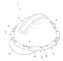
도 1은 본 발명의 일 실시예에 따른 스마트 헬멧의 사시도,
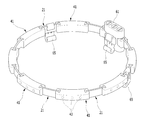
도 2는 도 1의 복수의 모듈 본체와 커넥터의 조립된 상태를 도시한 도면,
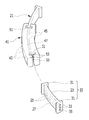
도 3은 도 1의 모듈 본체와 커넥터의 요부 분해사시도,
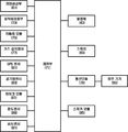
도 3은 본 발명의 일 실시예에 따른 모듈형 헤드 램프의 제어 블록도이다.1 is a perspective view of a smart helmet according to an embodiment of the present invention,
Figure 2 is a view showing an assembled state of the plurality of module body and connector of Figure 1,
Figure 3 is an exploded perspective view of main parts of the module body and connector of Figure 1,
3 is a control block diagram of a modular headlamp according to an embodiment of the present invention.
본 발명의 이점 및 특징, 그리고 그것들을 달성하는 방법은 첨부되는 도면과 함께 상세하게 후술되어 있는 실시예들을 참조하면 명확해질 것이다. 그러나, 본 발명은 이하에서 개시되는 실시예들에 제한되는 것이 아니라 서로 다른 다양한 형태로 구현될 수 있으며, 단지 본 실시예들은 본 발명의 개시가 완전하도록 하고, 본 발명이 속하는 기술 분야의 통상의 기술자에게 본 발명의 범주를 완전하게 알려주기 위해 제공되는 것이며, 본 발명은 청구항의 범주에 의해 정의될 뿐이다.Advantages and features of the present invention, and methods for achieving them will be clarified with reference to embodiments described below in detail together with the accompanying drawings. However, the present invention is not limited to the embodiments disclosed below, but may be implemented in various different forms, and only the embodiments allow the disclosure of the present invention to be complete, and are common in the technical field to which the present invention pertains. It is provided to fully inform the skilled person of the scope of the present invention, and the present invention is only defined by the scope of the claims.
본 명세서에서 사용된 용어는 실시예들을 설명하기 위한 것이며 본 발명을 제한하고자 하는 것은 아니다. 본 명세서에서, 단수형은 문구에서 특별히 언급하지 않는 한 복수형도 포함한다. 명세서에서 사용되는 "포함한다(comprises)" 및/또는 "포함하는(comprising)"은 언급된 구성요소 외에 하나 이상의 다른 구성요소의 존재 또는 추가를 배제하지 않는다. 명세서 전체에 걸쳐 동일한 도면 부호는 동일한 구성 요소를 지칭하며, "및/또는"은 언급된 구성요소들의 각각 및 하나 이상의 모든 조합을 포함한다. 비록 "제1", "제2" 등이 다양한 구성요소들을 서술하기 위해서 사용되나, 이들 구성요소들은 이들 용어에 의해 제한되지 않음은 물론이다. 이들 용어들은 단지 하나의 구성요소를 다른 구성요소와 구별하기 위하여 사용하는 것이다. 따라서, 이하에서 언급되는 제1 구성요소는 본 발명의 기술적 사상 내에서 제2 구성요소일 수도 있음은 물론이다.The terminology used herein is for describing the embodiments and is not intended to limit the present invention. In this specification, the singular form also includes the plural form unless otherwise specified in the phrase. As used herein, “comprises” and / or “comprising” does not exclude the presence or addition of one or more other components other than the components mentioned. Throughout the specification, the same reference numerals refer to the same components, and “and / or” includes each and every combination of one or more of the mentioned components. Although "first", "second", etc. are used to describe various components, it goes without saying that these components are not limited by these terms. These terms are only used to distinguish one component from another component. Therefore, it goes without saying that the first component mentioned below may be the second component within the technical spirit of the present invention.
다른 정의가 없다면, 본 명세서에서 사용되는 모든 용어(기술 및 과학적 용어를 포함)는 본 발명이 속하는 기술분야의 통상의 기술자에게 공통적으로 이해될 수 있는 의미로 사용될 수 있을 것이다. 또한, 일반적으로 사용되는 사전에 정의되어 있는 용어들은 명백하게 특별히 정의되어 있지 않는 한 이상적으로 또는 과도하게 해석되지 않는다.Unless otherwise defined, all terms (including technical and scientific terms) used in the present specification may be used as meanings commonly understood by those skilled in the art to which the present invention pertains. In addition, terms defined in the commonly used dictionary are not ideally or excessively interpreted unless explicitly defined.
이하, 첨부 도면을 참조하며, 본 발명에 대해 상세히 설명한다.Hereinafter, with reference to the accompanying drawings, the present invention will be described in detail.
도 1 내지 도 4에는 본 발명의 일 실시예에 따른 스마트 헬멧이 도시되어 있다.1 to 4 show a smart helmet according to an embodiment of the present invention.
이들 도면에 도시된 바와 같이 본 발명의 일 실시예에 따른 스마트 헬멧(1)은 헬멧 본체(11), 커넥터(21), 복수의 모듈 본체(41), 전원 공급부(61), 고정부를 포함한다.As shown in these drawings, the
헬멧 본체(11)는 착용자의 두피를 둘러싸며, 전방 일측에는 햇빛 등을 가리기 위한 챙(13)이 형성되어 있다.The
커넥터(21)는 도 3에 도시된 바와 같이, 커넥터 밴드(23)와 한 쌍의 결합구(31)를 포함한다.The
커넥터 밴드(23)는 일정 길이와 폭을 갖는 밴드 형상을 가지며, 전원을 제공하는 전원 케이블(25)이 노출되지 않게 수용되어 있다.The
한 쌍의 결합구(31)는 커넥터 밴드(23)의 양단부에 커넥터 밴드(23)의 길이방향에 대해 가로로 각각 돌출 형성된다. 이로써, 커넥터(21)는 전체적으로 'H'자 단면형상을 가진다.The pair of
또한, 각 결합구(31)에는 한 쌍의 전원단자 예컨대, (+)전원단자와 (-)전원단자가 노출되게 마련되어 있다. 이하에서는 설명의 편리상, 각 결합구(31)에 마련된 전원단자를 제1전원단자(33)라고 한다. 제1전원단자(33)는 전원 케이블(25)과 전기적으로 접속되어 외부로 전원을 제공한다.In addition, a pair of power terminals, for example, (+) power terminal and (-) power terminal are provided in each
한편, 본 발명에 따른 커넥터(21)는 데이터 통신을 위한 통신 케이블(27)을 더 포함한다.Meanwhile, the
통신 케이블(27)은 커넥터 밴드(23)에 노출되지 않게 수용된다. 또한, 각 결합구(31)에는 통신 케이블(27)과 전기적으로 접속되어 외부로 정보 데이터를 통신하기 위한 통신단자가 노출되게 마련된다. 이하에서는 설명의 편리상, 각 결합구(31)에 마련된 통신단자를 제1통신단자(35)라고 한다.The
이와 같이, 커넥터(21)에 제1전원단자(33) 뿐만 아니라 제1통신단자(35)도 구비함으로써, 커넥터(21)와 연결되는 외부 기기에 커넥터(21)를 통해 전원을 제공함과 동시에, 각종 정보 데이터를 제공할 수 있게 된다. As described above, by providing the
여기서, 커넥터(21)는, 야간이나 어두운 곳에서 용이하게 식별할 수 있도록, 야광물질을 함유하는 것이 보다 더 효과적이다. 또한, 커넥터(21)는 길이방향으로 신축가능한 소재로 이루어지는 것이 바람직하다. Here, the
모듈 본체(41)는 속이 빈 직사각형 단면의 블록 형상을 가지며, 헬멧 본체(11)의 둘레 방향을 따라 간격을 두고 배치된다. 본 실시예에서는 8개의 모듈 본체(41)가 마련되어 있지만, 모듈 본체(41)의 수량은 둘 이상 마련될 수 있다. 여기서, 모듈 본체(41)는 헬멧 본체(11)와 밀착력을 증대시키기 위해 일정 곡률반경을 가지며 벤딩 형성될 수 있다.The
각 모듈 본체(41)의 전면에는 빛을 발하는 복수의 발광체(43)가 마련되어 있다. 발광체(43)는 모듈 본체(41)에 수용되는 전원 케이블(45)에 의해 전기적으로 연결되어 있다. 여기서, 복수의 발광체(43)는 단일 색상의 빛을 발하는 발광다이오드, 또는 상이한 색상의 빛을 발하는 발광다이오드로 이루어질 수 있다. 또한, 각 모듈 본체(41)에는 하나의 발광체(43)만 마련될 수도 있다.A plurality of light-emitting
각 모듈 본체(41)의 양단부에는 커넥터(21)의 결합구(31)가 끼움 결합되는 끼움홈(51)이 형성되어 있다.On both ends of each
각 끼움홈(51)에는 커넥터(21)의 제1전원단자(33)와 전기적으로 접속되는 모듈 본체(41)의 전원단자가 노출되게 마련되어 있다. 이하에서는 설명의 편리상, 각 모듈 본체(41)에 마련된 전원단자를 제2전원단자(53)라고 한다. 각 모듈 본체(41)의 제2전원단자(53)는 발광체(43)에 연결된 전원 케이블(45)과 전기적으로 접속되어 있다.Each
또한, 각 끼움홈(51)에는 커넥터(21)의 제1통신단자(35)와 전기적으로 접속되는 모듈 본체(41)의 통신단자가 노출되게 마련되어 있다. 이하에서는 설명의 편리상, 각 모듈 본체(41)에 마련된 통신단자를 제2통신단자(55)라고 한다. 각 모듈 본체(41)의 제2통신단자(55)는 모듈 본체(41)에 수용되는 통신 케이블(47)에 의해 전기적으로 연결되어 있다.In addition, each
따라서, 인접하는 한 쌍의 모듈 본체(41)를 커넥터(21)로 상호 연결함에 따라, 도 2에 도시된 바와 같이 복수의 모듈 본체(41)는 폐루프 형상을 이루며 헬멧 본체(11)에 장착된다.Therefore, as a pair of
여기서, 모듈 본체(41)의 끼움홈(51)과 커넥터(21)의 결합구(31)는 억지끼워맞춤결합 또는 중간끼워맞춤결합되는 것이 바람직하다. 이로써, 외력에 의해 모듈 본체(41)와 커넥터(21)가 쉽게 분리되지 않게 되고, 특히 모듈 본체(41)와 커넥터(21)의 결합시, 커넥터(21)의 제1전원단자(33)와 모듈 본체(41)의 제2전원단자(53), 그리고 커넥터(21)의 제1통신단자(35)와 모듈 본체(41)의 제2통신단자(55)가 안정적으로 상호 밀착하며 전기적으로 접속될 수 있다. Here, it is preferable that the
한편, 복수의 모듈 본체(41) 중 어느 하나에는 복수의 모듈 본체(41)의 발광체(43)에 전원을 공급하는 전원 공급부(61)로서 배터리가 수용된다. 전원 공급부(61)가 마련되는 모듈 본체(41)에는 스위치(63)를 마련하여, 스위치(63)의 온 또는 오프 조작에 의해 배터리로부터 각 발광체(43)로 인가되는 전원을 제어할 수 있다.On the other hand, a battery is accommodated in one of the plurality of
고정부는 복수의 모듈 본체(41) 및 커넥터(21) 중 적어도 어느 하나에 마련되어, 복수의 모듈 본체(41)를 헬멧 본체(11)에 고정한다. 고정부는 헬멧 본체(11)에 끼움 결합되는 클립(65) 및 헬멧 본체(11)에 부착되는 접착 테이프 중 적어도 어느 하나가 마련될 수 있다.The fixing part is provided on at least one of the plurality of
헬멧 본체(11)의 측면에 배치되는 커넥터(21) 및 헬멧 본체(11)의 후방에 배치되는 모듈 본체(41)에는 고정부로서 클립(65)이 마련되어 있다. 클립(65)의 일단부는 커넥터(21) 또는 모듈 본체(41)에 걸리고, 타단부는 탄성 변형가능하게 절곡 연장 형성되어 있다. 클립(65)의 타단부가 헬멧 본체(11)의 단부에 삽입되며 탄성력에 의해 헬멧 본체(11)의 내측면과 외측면에 밀착 즉, 헬멧 본체(11)의 둘레에 끼움 결합된다. 클립(65)이 헬멧 본체(11)의 둘레에 끼움 결합될 때, 각 모듈 본체(41)는 커넥터(21)의 탄성력 및 클립(65)에 의해 헬멧 본체(11)의 외측면에 견고하게 밀착된다.A
여기서, 도시되어 있지 않지만, 클립(65)이 장착된 모듈 본체(41)에 클립(65) 대신에, 고정부로서 접착성이 우수한 접착 테이프를 마련하여, 모듈 본체(41)를 헬멧 본체(11)의 외측면에 견고하게 고정할 수도 있다. 또한, 헬멧 본체(11)의 전방 및 양측면에 배치되는 모듈 본체(41)의 배면에 접착 테이프를 마련하여, 각 모듈 본체(41)를 헬멧 본체(11)에 견고하게 고정할 수도 있다.Here, although not shown, instead of the
이러한 구성에 의하여, 복수의 커넥터(21)로 복수의 모듈 본체(41)를 상호 연결하여, 복수의 모듈 본체(41)를 도 2에 도시된 바와 같이 폐루프 형상으로 형성한 후, 복수의 모듈 본체(41)를 헬멧 본체(11)의 둘레를 따라 위치시킴과 동시에, 커넥터(21) 및 모듈 본체(41)에 장착된 클립(65)을 헬멧 본체(11)의 둘레에 끼움 결합함으로써, 본 발명의 일 실시예에 따른 스마트 헬멧(1)을 얻을 수 있게 된다.With this configuration, a plurality of
이로써, 각 모듈 본체(41)는 고정부와 커넥터(21)에 의해 외부 물체와의 충돌시 쉽게 벗겨지지 않으며 헬멧 본체(11)에 견고하게 고정될 수 있고, 또한 복수의 모듈 본체(41)를 헬멧 본체(11)의 둘레를 따라 배치하여 착용자 주변을 폭넓게 조명하며, 야간이나 어두운 곳에서의 사고를 미연에 방지할 수 있게 된다. 또한, 모듈 본체(41)를 모듈화하여, 고장 및 파손된 모듈 본체(41)만을 간편하게 교체하며 사용할 수 있고, 자원의 낭비를 줄일 수 있게 된다.Accordingly, each
한편, 본 발명의 일 실시예에 따른 스마트 헬멧(1)은 움직임 검출부(73)를 더 포함한다.Meanwhile, the
움직임 검출부(73)는 모듈 본체(41)에 마련되어, 모듈 본체(41)의 움직임을 검출한다. 움직임 검출부(73)는 하나의 모듈 본체, 또는 일부의 모듈 본체, 또는 모듈 본체의 전체에 마련될 수 있다. 여기서, 움직임 검출부(73)는 9축모션센서, 자이로 센서, 가속도계 센서 중 적어도 어느 하나로 마련될 수 있다.The
한편, 움직임 검출부(73)에서 감지된 신호는 각 통신 케이블(27,47)과 각 통신단자(35,55)를 통해 제어부(71)로 전달되어, 제어부(71)는 움직임 검출부(73)의 감지된 신호에 따라 전원 공급부(61)로부터 발광체(43)로 인가되는 전원을 제어한다. 예컨대, 헬멧(1)을 한번 움직이면 이에 따른 움직임 검출부(73)의 신호에 의해 제어부(71)는 전원 공급부(61)로부터 발광체(43)로 전원이 인가되도록 제어하고, 헬멧(1)을 두 번 움직이면 이에 따른 움직임 검출부(73)의 신호에 의해 제어부(71)는 전원 공급부(61)로부터 발광체(43)로 전원이 인가되지 않도록 제어할 수 있다. 이로써, 헬멧(1) 착용자가 스위치(63)의 조작없이 헬멧(1)을 착용한 채로 헬멧(1)의 좌우 요동에 의해 편리하게 전원 인가를 제어할 수 있다. On the other hand, the signal detected by the
또한, 본 발명의 일 실시예에 따른 카메라 모듈(75)과, 가스 감지센서(77)와, 통신 모듈(79)과, GPS 모듈(81)과, 공기압센서(83)와, 스피커 모듈(85)과, 마이크 모듈(87)과, 온도센서(89)와, 습도센서(91)를 더 포함할 수 있다.In addition, the
카메라 모듈(75)은 하나의 모듈 본체, 또는 일부의 모듈 본체, 또는 모듈 본체의 전체에 마련되어, 모듈 본체(41)의 주변을 촬영한다. 하나의 모듈 본체에만 카메라 모듈(75)이 마련된 경우 특정 방향의 영상을 촬영할 수 있게 되고, 일부의 모듈 본체 또는 전체의 모듈 본체에 카메라 모듈(75)이 마련된 경우 360도 각도의 VR(Virtual Reality) 영상을 촬영할 수 있게 된다. 카메라 모듈(75)을 통해 촬영된 영상 데이터는 제어부(71)에 저장되거나, 통신 모듈(79)을 통해 실시간으로 외부 기기(95)에 전송될 수 있다.The
가스 감지센서(77)는 하나의 모듈 본체, 또는 일부의 모듈 본체, 또는 모듈 본체의 전체에 마련되어, 모듈 본체(41)의 주변에 대한 가스 성분 일 예로서, 산소 농도 또는 일산화탄소 등의 유해 가스 농도를 감지한다. 가스 감지센서(77)를 통해 감지된 가스 성분 데이터는 제어부(71)에 저장되거나, 통신 모듈(79)을 통해 실시간으로 외부 기기(95)에 전송될 수 있다.The
통신 모듈(79)은 하나의 모듈 본체(41)에 마련되어, 외부 기기(95)와 무선 송신한다. 통신 모듈(79)은 모듈 본체(41)의 주변에 대한 각종 정보 데이터를 실시간으로 외부 기기(95)에 전송한다.The
GPS 모듈(81)은 하나의 모듈 본체(41)에 마련되어, 고정국 또는 인공위성으로부터 모듈 본체(41)의 위치 데이터를 수신한다. GPS 모듈(81)을 통해 수신된 위치 데이터는 제어부(71)에 저장되거나, 통신 모듈(79)을 통해 실시간으로 외부 기기(95)에 전송될 수 있다.The
공기압센서(83)는 하나의 모듈 본체(41)에 마련되어, 모듈 본체(41)의 주변에 대한 공기압을 감지한다. 공기압센서(83)를 통해 수신된 공기압에 따른 고도 데이터는 제어부(71)에 저장되거나, 통신 모듈(79)을 통해 실시간으로 외부 기기(95)에 전송될 수 있다.The
스피커 모듈(85)은 하나의 모듈 본체, 또는 일부의 모듈 본체, 또는 모듈 본체의 전체에 마련되어, 모듈 본체(41)의 주변에 소리를 출력한다. 스피커 모듈(85)은 외부 기기(95)로부터 통신 모듈(79)을 통해 수신한 음성 데이터를 실시간으로 모듈 본체(41)의 주변에 출력할 수 있다.The
마이크 모듈(87)은 하나의 모듈 본체, 또는 일부의 모듈 본체, 또는 모듈 본체의 전체에 마련되어, 모듈 본체(41)의 주변의 소리를 수신한다. 마이크 모듈(87)을 통해 수신된 음성 데이터는 제어부(71)에 저장되거나, 통신 모듈(79)을 통해 실시간으로 외부 기기(95)에 전송될 수 있다. 이와 같이, 마이크 모듈(87)과 스피커 모듈(85)을 마련함으로써, 본 발명에 따른 헬멧(1) 착용자는 마이크 모듈(87)과 스피커 모듈(85)을 통해 제3자와 통화를 할 수 있게 된다.The
온도센서(89)는 하나의 모듈 본체(41)에 마련되어, 모듈 본체(41)의 주변에 대한 온도를 감지한다. 온도센서(89)를 통해 감지된 온도 데이터는 제어부(71)에 저장되거나, 통신 모듈(79)을 통해 실시간으로 외부 기기(95)에 전송될 수 있다.The
습도센서(91)는 하나의 모듈 본체(41)에 마련되어, 모듈 본체(41)의 주변에 대한 습도를 감지한다. 습도센서(91)를 통해 감지된 습도 데이터는 제어부(71)에 저장되거나, 통신 모듈(79)을 통해 실시간으로 외부 기기(95)에 전송될 수 있다.The
한편, 제어부(71)는 전원 공급부(61)로부터 발광체(43), 카메라 모듈(75), 가스 감지센서(77), 통신 모듈(79), GPS 모듈(81), 공기압센서(83), 스피커 모듈(85), 마이크 모듈(87), 온도센서(89), 습도센서(91)로의 전원 공급을 제어한다.On the other hand, the
또한, 제어부(71)는 카메라 모듈(75)을 통해 촬영된 영상 데이터, 가스 감지센서(77)를 통해 감지된 가스 성분 데이터, GPS 모듈(81)을 통해 수신된 위치 데이터, 공기압센서(83)를 통해 수신된 공기압에 따른 고도 데이터, 마이크 모듈(87)을 통해 수신된 음성 데이터, 온도센서(89)를 통해 감지된 온도 데이터, 습도센서(91)를 통해 감지된 습도 데이터를 저장하고, 이들 데이터가 통신 모듈(79)을 통해 외부 기기(95)로 송신되도록 제어한다. 또한, 제어부(71)는 외부 기기(95)로부터 통신 모듈(79)을 통해 수신한 음성 데이터를 실시간으로 스피커 모듈(85)을 통해 출력하도록 제어한다.In addition, the
이러한 카메라 모듈(75), 가스 감지센서(77), 통신 모듈(79), GPS 모듈(81), 공기압센서(83), 스피커 모듈(85), 마이크 모듈(87), 온도센서(89), 습도센서(91)를 마련함으로써, 헬멧(1) 착용자의 주변에 대한 각종 정보를 원격지에서도 실시간으로 모니터링할 수 있게 된다.Such a
이와 같이, 본 발명에 따르면, 발광체를 구비하는 모듈 본체들을 상호 연결하는 커넥터에 전원 케이블 및 전원단자를 마련하고, 커넥터의 양단부에는 각 모듈 본체와 끼움결합되는 결합구를 형성함으로써, 외부 물체와의 충돌에 의해 쉽게 벗겨지지 않으며 헬멧에 견고하게 고정할 수 있고, 발광체를 구비한 복수의 모듈 본체를 간편하게 전기적으로 접속함과 동시에, 상호 연결하며 헬멧의 둘레를 따라 배치하여 착용자 주변을 폭넓게 조명하고, 야간이나 어두운 곳에서의 사고를 미연에 방지할 수 있게 된다.As described above, according to the present invention, a power cable and a power terminal are provided in a connector that interconnects the module bodies having a light emitting body, and at both ends of the connector, coupling holes are fitted to each module body to form a connection with an external object. It is not easily peeled off by a collision and can be securely fixed to the helmet, easily connects a plurality of module bodies with light emitters, and at the same time, interconnects and arranges along the circumference of the helmet to illuminate the wearer's perimeter widely, It is possible to prevent an accident at night or in a dark place.
또한, 커넥터에 전원단자 뿐만 아니라 통신단자도 구비함으로써, 커넥터와 연결되는 외부 기기에 커넥터를 통해 전원을 제공함과 동시에, 각종 정보 데이터를 제공할 수 있게 된다.In addition, by providing a communication terminal as well as a power terminal in the connector, it is possible to provide power to the external device connected to the connector through the connector and provide various information data.
또한, 발광체가 구비된 모듈 본체를 모듈화하여, 고장 및 파손된 모듈 본체만을 간편하게 교체하며 사용할 수 있고, 자원의 낭비를 줄일 수 있게 된다.In addition, by modularizing the module body provided with the light emitting body, it is possible to easily replace and use only the broken and damaged module body, thereby reducing the waste of resources.
그리고, 모듈 본체의 주변에 대한 정보를 원격지에서도 실시간으로 모니터링할 수 있게 된다.And, it is possible to monitor the information about the periphery of the module body in real time even at a remote location.
이상, 첨부된 도면을 참조로 하여 본 발명의 실시예를 설명하였지만, 본 발명이 속하는 기술분야의 통상의 기술자는 본 발명이 그 기술적 사상이나 필수적인 특징을 변경하지 않고서 다른 구체적인 형태로 실시될 수 있다는 것을 이해할 수 있을 것이다. 그러므로, 이상에서 기술한 실시예들은 모든 면에서 예시적인 것이며, 제한적이 아닌 것으로 이해해야만 한다.The embodiments of the present invention have been described above with reference to the accompanying drawings, but a person skilled in the art to which the present invention pertains may implement the present invention in other specific forms without changing its technical spirit or essential features. You will understand. Therefore, it should be understood that the above-described embodiments are illustrative in all respects and not restrictive.
1 : 스마트 헬멧 11 : 헬멧 본체
21 : 커넥터 23 : 커넥터 밴드
31 : 결합구 41 : 모듈 본체
43 : 발광체 51 : 끼움홈
61 : 전원 공급부 63 : 스위치
65 : 클립 71 : 제어부
73 : 움직임 검출부 75 : 카메라 모듈
79 : 통신 모듈 81 : GPS 모듈
83 : 공기압센서 85 : 스피커 모듈
87 : 마이크 모듈 89 : 온도센서
91 : 습도센서 95 : 외부 기기1: Smart helmet 11: Helmet body
21: connector 23: connector band
31: coupling 41: module body
43: light emitter 51: fitting groove
61: power supply 63: switch
65: Clip 71: Control
73: motion detection unit 75: camera module
79: communication module 81: GPS module
83: air pressure sensor 85: speaker module
87: microphone module 89: temperature sensor
91: humidity sensor 95: external device
Claims (17)
상기 전원 케이블과 전기적으로 접속되어 외부로 전원을 제공하기 위한 전원단자를 가지며, 상기 커넥터 밴드의 양단부에 상기 커넥터 밴드의 길이방향에 대해 가로로 각각 돌출된 한 쌍의 결합구를 포함하는, 커넥터.A band-shaped connector band in which a power cable providing power is accommodated; And
A connector that is electrically connected to the power cable and has a power terminal for providing power to the outside, and includes a pair of coupling holes protruding horizontally with respect to the longitudinal direction of the connector band at both ends of the connector band.
상기 커넥터 밴드에는 데이터 통신을 위한 통신 케이블이 수용되고, 상기 결합구에는 상기 통신 케이블과 전기적으로 접속되어 외부로 정보 데이터를 통신하기 위한 통신단자가 마련되는, 커넥터.According to claim 1,
A communication cable for data communication is accommodated in the connector band, and a communication terminal is provided at the coupling port to be electrically connected to the communication cable to communicate information data to the outside.
전원을 제공하는 전원 케이블이 수용된 밴드 형상의 커넥터 밴드와, 상기 전원 케이블과 전기적으로 접속되어 외부로 전원을 제공하기 위한 제1전원단자를 가지며 상기 커넥터 밴드의 양단부에 상기 커넥터 본체의 길이방향에 대해 가로로 각각 돌출된 한 쌍의 결합구를 포함하는 커넥터;
양단부에 상기 커넥터의 결합구가 끼움 결합되는 끼움홈과, 상기 끼움홈에 마련되어 상기 제1전원단자와 전기적으로 접속하는 제2전원단자와, 하나 이상의 발광체를 가지며, 상기 커넥터에 의해 폐루프 형상으로 상호 연결되어 상기 헬멧 본체에 장착되는 복수의 모듈 본체;
상기 복수의 모듈 본체 중 어느 하나에 마련되어, 상기 복수의 모듈 본체의 발광체에 전원을 공급하는 전원 공급부; 및
상기 복수의 모듈 본체 및 상기 커넥터 중 적어도 어느 하나에 마련되어, 상기 헬멧 본체에 고정하는 고정부를 포함하는, 스마트 헬멧.Helmet body;
A band-shaped connector band in which a power cable for providing power is accommodated, and a first power terminal for providing power to the outside by being electrically connected to the power cable and having both ends of the connector band with respect to the longitudinal direction of the connector body. A connector including a pair of coupling holes protruding horizontally;
It has a fitting groove in which the fittings of the connector are fitted to both ends, a second power terminal provided in the fitting groove and electrically connected to the first power terminal, and at least one light emitting body, and is closed looped by the connector. A plurality of module bodies connected to each other and mounted to the helmet body;
A power supply unit provided on any one of the plurality of module bodies to supply power to the light emitting bodies of the plurality of module bodies; And
A smart helmet provided on at least one of the plurality of module bodies and the connector and including a fixing part fixed to the helmet body.
상기 커넥터 밴드에는 데이터 통신을 위한 통신 케이블이 수용되고, 상기 결합구에는 상기 통신 케이블과 전기적으로 접속되어 외부로 통신 데이터를 제공하기 위한 통신단자가 마련되는, 스마트 헬멧.According to claim 3,
A communication cable for data communication is accommodated in the connector band, and a communication terminal for providing communication data to the outside is electrically connected to the communication cable, and a smart helmet is provided in the coupling port.
하나 이상의 상기 모듈 본체에 마련되어, 상기 모듈 본체의 움직임을 검출하는 움직임 검출부; 및
상기 움직임 검출부의 감지된 신호에 따라 상기 전원 공급부로부터 상기 발광체로 인가되는 전원을 제어하는 제어부를 포함하는, 스마트 헬멧.According to claim 3,
A motion detection unit provided on one or more of the module bodies and detecting movement of the module bodies; And
And a control unit that controls power applied from the power supply unit to the light emitter according to the detected signal of the motion detection unit.
상기 움직임 검출부는 9축모션센서, 자이로 센서, 가속도계 센서 중 적어도 어느 하나인, 스마트 헬멧.The method of claim 5,
The motion detector is at least one of a 9-axis motion sensor, a gyro sensor, and an accelerometer sensor, a smart helmet.
상기 모듈 본체에 마련되어, 상기 전원 공급부로부터 상기 발광체로 인가되는 전원을 온 또는 오프하는 스위치를 더 포함하는, 스마트 헬멧.According to claim 3,
It is provided in the module body, the smart helmet further comprises a switch for turning on or off the power applied to the light source from the power supply.
하나 이상의 상기 모듈 본체에 마련되어, 상기 모듈 본체의 주변을 촬영하는 카메라 모듈을 더 포함하는, 스마트 헬멧.According to claim 3,
Smart helmet, provided in one or more of the module body, further comprising a camera module for photographing the periphery of the module body.
하나 이상의 상기 모듈 본체에 마련되어, 상기 모듈 본체의 주변에 대한 가스 성분을 감지하는 가스 감지센서를 더 포함하는, 스마트 헬멧.According to claim 3,
Smart helmet, provided in one or more of the module body, further comprising a gas detection sensor for detecting a gas component to the periphery of the module body.
하나의 상기 모듈 본체에 마련되어, 상기 모듈 본체의 주변에 대한 정보 데이터를 외부 기기에 송신하는 통신 모듈을 더 포함하는, 스마트 헬멧.According to claim 3,
Smart helmet, provided in one of the module body, further comprising a communication module for transmitting information data about the periphery of the module body to an external device.
하나의 상기 모듈 본체에 마련되어, 상기 모듈 본체의 주변에 대한 위치 정보를 수신하는 GPS 모듈을 더 포함하는, 스마트 헬멧.According to claim 3,
A smart helmet provided on one of the module bodies and further comprising a GPS module for receiving location information about the periphery of the module body.
하나의 상기 모듈 본체에 마련되어, 상기 모듈 본체의 주변에 대한 공기압을 측정하는 공기압센서를 더 포함하는, 스마트 헬멧.According to claim 3,
Smart helmet, provided in one of the module body, further comprising an air pressure sensor for measuring air pressure to the periphery of the module body.
하나의 상기 모듈 본체에 마련되어, 상기 모듈 본체의 주변에 소리를 출력하는 스피커 모듈을 더 포함하는, 스마트 헬멧.According to claim 3,
A smart helmet provided on one of the module bodies and further comprising a speaker module that outputs sound to the periphery of the module body.
하나의 상기 모듈 본체에 마련되어, 상기 모듈 본체의 주변의 소리를 수신하는 마이크 모듈을 더 포함하는, 스마트 헬멧.According to claim 3,
Smart helmet, provided in one of the module body, further comprising a microphone module for receiving sound around the module body.
하나의 상기 모듈 본체에 마련되어, 상기 모듈 본체의 주변에 대한 온도를 측정하는 온도센서를 더 포함하는, 스마트 헬멧.According to claim 3,
Smart helmet provided on one of the module bodies, further comprising a temperature sensor for measuring the temperature of the periphery of the module body.
하나의 상기 모듈 본체에 마련되어, 상기 모듈 본체의 주변에 대한 습도를 측정하는 습도센서를 더 포함하는, 스마트 헬멧.According to claim 3,
A smart helmet provided on one of the module bodies and further comprising a humidity sensor for measuring humidity with respect to the periphery of the module body.
상기 고정부는 상기 헬멧 본체에 끼움 결합되는 클립 및 상기 헬멧 본체에 부착되는 접착 테이프 중 적어도 어느 하나를 포함하는, 스마트 헬멧.According to claim 3,
The fixing part includes at least one of a clip fitted to the helmet body and an adhesive tape attached to the helmet body, a smart helmet.
Priority Applications (1)
| Application Number | Priority Date | Filing Date | Title |
|---|---|---|---|
| KR1020200038955A KR20200038902A (en) | 2020-03-31 | 2020-03-31 | Connector and smart helmet using the same |
Applications Claiming Priority (1)
| Application Number | Priority Date | Filing Date | Title |
|---|---|---|---|
| KR1020200038955A KR20200038902A (en) | 2020-03-31 | 2020-03-31 | Connector and smart helmet using the same |
Related Parent Applications (1)
| Application Number | Title | Priority Date | Filing Date |
|---|---|---|---|
| KR1020200038744 Division | 2020-03-31 |
Publications (1)
| Publication Number | Publication Date |
|---|---|
| KR20200038902A true KR20200038902A (en) | 2020-04-14 |
Family
ID=70291563
Family Applications (1)
| Application Number | Title | Priority Date | Filing Date |
|---|---|---|---|
| KR1020200038955A KR20200038902A (en) | 2020-03-31 | 2020-03-31 | Connector and smart helmet using the same |
Country Status (1)
| Country | Link |
|---|---|
| KR (1) | KR20200038902A (en) |
Cited By (4)
| Publication number | Priority date | Publication date | Assignee | Title |
|---|---|---|---|---|
| KR102183231B1 (en) * | 2020-05-08 | 2020-11-26 | 지정현 | System for monitoring construction site environmental pollution and method performing thereof |
| CN112153516A (en) * | 2020-09-29 | 2020-12-29 | 国网江苏省电力有限公司镇江供电分公司 | Cloud supervision intelligent monitoring ring |
| USD976462S1 (en) * | 2021-11-08 | 2023-01-24 | Fuguang Liu | Lamp |
| KR102568921B1 (en) * | 2023-04-21 | 2023-08-22 | 대한민국 | Impact sensing frame detachable from safety helmet |
Citations (1)
| Publication number | Priority date | Publication date | Assignee | Title |
|---|---|---|---|---|
| KR200433252Y1 (en) | 2006-09-14 | 2006-12-08 | 장위덕 | Light emitting safety helmet |
-
2020
- 2020-03-31 KR KR1020200038955A patent/KR20200038902A/en active Application Filing
Patent Citations (1)
| Publication number | Priority date | Publication date | Assignee | Title |
|---|---|---|---|---|
| KR200433252Y1 (en) | 2006-09-14 | 2006-12-08 | 장위덕 | Light emitting safety helmet |
Cited By (5)
| Publication number | Priority date | Publication date | Assignee | Title |
|---|---|---|---|---|
| KR102183231B1 (en) * | 2020-05-08 | 2020-11-26 | 지정현 | System for monitoring construction site environmental pollution and method performing thereof |
| KR20210136820A (en) * | 2020-05-08 | 2021-11-17 | 지정현 | Safety helmet for construction site monitoring and monitoring method using a safety helmet |
| CN112153516A (en) * | 2020-09-29 | 2020-12-29 | 国网江苏省电力有限公司镇江供电分公司 | Cloud supervision intelligent monitoring ring |
| USD976462S1 (en) * | 2021-11-08 | 2023-01-24 | Fuguang Liu | Lamp |
| KR102568921B1 (en) * | 2023-04-21 | 2023-08-22 | 대한민국 | Impact sensing frame detachable from safety helmet |
Similar Documents
| Publication | Publication Date | Title |
|---|---|---|
| KR20200038902A (en) | Connector and smart helmet using the same | |
| KR20180010083A (en) | Connector and smart helmet using the same | |
| US8015626B2 (en) | Safety helmet with module ring | |
| US5648862A (en) | Night vision device with audio communication and identification facility | |
| US5743621A (en) | Illuminated safety helmet | |
| US7377665B2 (en) | Buckle-mounted light | |
| US6250769B1 (en) | Visor light cap | |
| WO2013168899A1 (en) | Helmet and a method for dealing with an accident using the helmet | |
| US20060198122A1 (en) | Illuminated headwear | |
| US20090073679A1 (en) | Helmet LED lighting system | |
| US10076142B2 (en) | Durable reflective safety apparel with active laser illumination | |
| US9144261B2 (en) | Combination marker light and infrared interrogation device | |
| US5353205A (en) | Cockpit blackout search & survival light | |
| US20100302502A1 (en) | Glasses with illumination function | |
| WO2006070724A1 (en) | Solar visual recognizing device | |
| KR102051214B1 (en) | System for Controlling Smart Safety Helmet for Safety Management of Worker and Communication | |
| KR100777667B1 (en) | Fire fighting helmet | |
| WO2017055804A1 (en) | Illumination system for a safety helmet | |
| RU2276964C2 (en) | Head device for illumination and shooting of objects used in medicine | |
| CN219088509U (en) | Safety helmet | |
| US20240050782A1 (en) | Wearable air purifier | |
| US11739928B2 (en) | Safety light | |
| US20240050777A1 (en) | Wearable air purifier | |
| KR102440897B1 (en) | Wearable device for safe walking at night | |
| CN212814622U (en) | Headlight module of intelligence fire helmet |
Legal Events
| Date | Code | Title | Description |
|---|---|---|---|
| A107 | Divisional application of patent |