KR20200038477A - Modular air cooling and distribution system and method - Google Patents
Modular air cooling and distribution system and method Download PDFInfo
- Publication number
- KR20200038477A KR20200038477A KR1020207004277A KR20207004277A KR20200038477A KR 20200038477 A KR20200038477 A KR 20200038477A KR 1020207004277 A KR1020207004277 A KR 1020207004277A KR 20207004277 A KR20207004277 A KR 20207004277A KR 20200038477 A KR20200038477 A KR 20200038477A
- Authority
- KR
- South Korea
- Prior art keywords
- fan
- heat exchanger
- assembly
- fluid
- exchanger assembly
- Prior art date
Links
- 238000001816 cooling Methods 0.000 title claims abstract description 72
- 238000000034 method Methods 0.000 title claims description 19
- 239000012530 fluid Substances 0.000 claims abstract description 82
- 230000000712 assembly Effects 0.000 claims abstract description 23
- 238000000429 assembly Methods 0.000 claims abstract description 23
- 238000004891 communication Methods 0.000 claims description 14
- 238000005259 measurement Methods 0.000 abstract description 12
- XLYOFNOQVPJJNP-UHFFFAOYSA-N water Substances O XLYOFNOQVPJJNP-UHFFFAOYSA-N 0.000 abstract description 7
- 238000012546 transfer Methods 0.000 abstract description 2
- DNIAPMSPPWPWGF-UHFFFAOYSA-N Propylene glycol Chemical group CC(O)CO DNIAPMSPPWPWGF-UHFFFAOYSA-N 0.000 abstract 3
- 239000000498 cooling water Substances 0.000 description 7
- 239000007788 liquid Substances 0.000 description 4
- LYCAIKOWRPUZTN-UHFFFAOYSA-N Ethylene glycol Chemical compound OCCO LYCAIKOWRPUZTN-UHFFFAOYSA-N 0.000 description 2
- 238000009529 body temperature measurement Methods 0.000 description 2
- 238000013461 design Methods 0.000 description 2
- 238000010586 diagram Methods 0.000 description 2
- 238000012986 modification Methods 0.000 description 2
- 230000004048 modification Effects 0.000 description 2
- 230000001133 acceleration Effects 0.000 description 1
- XAGFODPZIPBFFR-UHFFFAOYSA-N aluminium Chemical compound [Al] XAGFODPZIPBFFR-UHFFFAOYSA-N 0.000 description 1
- 229910052782 aluminium Inorganic materials 0.000 description 1
- 238000007664 blowing Methods 0.000 description 1
- 239000012809 cooling fluid Substances 0.000 description 1
- 238000005265 energy consumption Methods 0.000 description 1
- WGCNASOHLSPBMP-UHFFFAOYSA-N hydroxyacetaldehyde Natural products OCC=O WGCNASOHLSPBMP-UHFFFAOYSA-N 0.000 description 1
- 238000002955 isolation Methods 0.000 description 1
- 238000011084 recovery Methods 0.000 description 1
- 239000003507 refrigerant Substances 0.000 description 1
- 239000007858 starting material Substances 0.000 description 1
Images


Classifications
-
- H—ELECTRICITY
- H05—ELECTRIC TECHNIQUES NOT OTHERWISE PROVIDED FOR
- H05K—PRINTED CIRCUITS; CASINGS OR CONSTRUCTIONAL DETAILS OF ELECTRIC APPARATUS; MANUFACTURE OF ASSEMBLAGES OF ELECTRICAL COMPONENTS
- H05K7/00—Constructional details common to different types of electric apparatus
- H05K7/20—Modifications to facilitate cooling, ventilating, or heating
- H05K7/20709—Modifications to facilitate cooling, ventilating, or heating for server racks or cabinets; for data centers, e.g. 19-inch computer racks
- H05K7/20836—Thermal management, e.g. server temperature control
-
- H—ELECTRICITY
- H05—ELECTRIC TECHNIQUES NOT OTHERWISE PROVIDED FOR
- H05K—PRINTED CIRCUITS; CASINGS OR CONSTRUCTIONAL DETAILS OF ELECTRIC APPARATUS; MANUFACTURE OF ASSEMBLAGES OF ELECTRICAL COMPONENTS
- H05K7/00—Constructional details common to different types of electric apparatus
- H05K7/20—Modifications to facilitate cooling, ventilating, or heating
- H05K7/20709—Modifications to facilitate cooling, ventilating, or heating for server racks or cabinets; for data centers, e.g. 19-inch computer racks
- H05K7/20718—Forced ventilation of a gaseous coolant
- H05K7/20745—Forced ventilation of a gaseous coolant within rooms for removing heat from cabinets, e.g. by air conditioning device
-
- H—ELECTRICITY
- H05—ELECTRIC TECHNIQUES NOT OTHERWISE PROVIDED FOR
- H05K—PRINTED CIRCUITS; CASINGS OR CONSTRUCTIONAL DETAILS OF ELECTRIC APPARATUS; MANUFACTURE OF ASSEMBLAGES OF ELECTRICAL COMPONENTS
- H05K7/00—Constructional details common to different types of electric apparatus
- H05K7/20—Modifications to facilitate cooling, ventilating, or heating
- H05K7/20009—Modifications to facilitate cooling, ventilating, or heating using a gaseous coolant in electronic enclosures
- H05K7/20136—Forced ventilation, e.g. by fans
- H05K7/20145—Means for directing air flow, e.g. ducts, deflectors, plenum or guides
Abstract
모듈식 공기 냉각 및 분배 시스템은 냉각용 팬 및 열교환기 조립체와 온도 및 속도 측정값에 따라 팬 속도를 제어하는 제어기를 포함한다. 냉각용 조립체는 유체-공기 열교환기와 가변 속도 팬을 포함한다. 유체-공기 열교환기의 유체는 프로필렌글리콜 또는 물일 수 있다. 열교환기는 압력 저하를 최소화하고 열 전달을 최대화한다. 냉각용 조립체의 수량은 옥내 냉각 요건에 맞게 선택된다. 냉각용 조립체는 조립이 용이하고, 냉각 부하에 부합하도록 수직 방향으로 적층되고/되거나 수평 방향으로 연결된다. 향후 추가적인 냉각 용량이 필요할 경우, 냉각용 조립체는 용이하게 추가될 수 있고, 수직 및/또는 수평방향으로 확장될 수 있다. 팬 및 열교환기 조립체의 팬의 속도는 풍속계를 사용하여 구할 수 있는 유체 온도 및 유체 속도 측정값에 기초하여 제어된다.The modular air cooling and distribution system includes a cooling fan and heat exchanger assembly and a controller that controls the fan speed according to temperature and speed measurements. The cooling assembly includes a fluid-air heat exchanger and a variable speed fan. The fluid of the fluid-air heat exchanger can be propylene glycol or water. The heat exchanger minimizes pressure drop and maximizes heat transfer. The quantity of cooling assemblies is selected to meet indoor cooling requirements. The assembly for cooling is easy to assemble and is stacked in the vertical direction and / or connected in the horizontal direction to meet the cooling load. In the future, if additional cooling capacity is required, the cooling assembly can be easily added and extended vertically and / or horizontally. The fan speed of the fan and heat exchanger assembly is controlled based on the fluid temperature and fluid velocity measurements available using an anemometer.

Description
본 발명은 냉각 시스템에 관한 것이다.The present invention relates to a cooling system.
데이터 센터의 서버 랙은 대량의 열을 발생시키는 많은 수의 전자 장치를 포함한다. 따라서, 많은 양의 전력이 전자 장치를 냉각시키기 위해 필요하다. 큰 전력 소비의 한 요인은 서버 랙에 냉각 유체 또는 공기를 공급하는 방식이다.Server racks in data centers contain a large number of electronic devices that generate large amounts of heat. Therefore, a large amount of power is required to cool the electronic device. One factor in high power consumption is how cooling fluid or air is supplied to the server rack.
일 양태에서, 본 개시는 냉각 시스템을 제공한다.In one aspect, the present disclosure provides a cooling system.
냉각 시스템은 건물의 제1 천장과 제2 천장 사이에 형성되는 천장 플레넘(plenum)과, 서버 랙 열(rows of server racks)에 의해 형성되는 적어도 하나의 열기 통로 상부에 배치되고 상기 제1 천장의 개구부를 통해 연장되는 차폐 조립체를 포함한다. 차폐 조립체는 유체를 열기 통로에서 천장 플레넘 내로 향하게 한다. 냉각 시스템은 열기 통로 또는 차폐 조립체 내를 유동하는 유체의 속도를 측정하는 유속 센서와, 열기 통로 또는 차폐 조립체 내를 유동하는 유체의 온도를 측정하는 온도 센서를 포함한다. 차폐 조립체는 적어도 하나의 팬 및 열교환기 조립체와, 측정된 온도 및 속도에 기초하여 적어도 하나의 팬 및 열교환기 조립체의 적어도 하나의 팬의 속도를 조절하는 제어기를 포함한다. 적어도 하나의 팬 및 열교환기 조립체의 적어도 하나의 팬은 유체를 적어도 하나의 팬 및 열교환기 조립체의 적어도 하나의 열교환기를 통해 천장 플레넘에서 복수의 서버 랙으로 유동시킨다.The cooling system is disposed over the ceiling plenum formed between the first and second ceilings of the building and at least one hot aisle formed by rows of server racks, and the first ceiling It includes a shield assembly extending through the opening of the. The shield assembly directs fluid from the hot aisle into the ceiling plenum. The cooling system includes a flow rate sensor that measures the velocity of the fluid flowing in the hot-aisle or shield assembly, and a temperature sensor that measures the temperature of the fluid flowing in the hot-aisle or shield assembly. The shield assembly includes at least one fan and heat exchanger assembly and a controller that adjusts the speed of at least one fan of the at least one fan and heat exchanger assembly based on the measured temperature and speed. At least one fan and at least one fan of the heat exchanger assembly flow fluid through the at least one fan and at least one heat exchanger of the heat exchanger assembly from the ceiling plenum to the plurality of server racks.
본 개시의 양태에서, 적어도 하나의 팬 및 열교환기 조립체는 복수의 팬 및 열교환기 조립체로 구성된 제1 팬 및 열교환기 조립체 열과, 제1 팬 및 열교환기 조립체 열에 인접한 복수의 팬 및 열교환기 조립체로 구성된 제2 팬 및 열교환기 조립체 열을 포함한다.In aspects of the present disclosure, the at least one fan and heat exchanger assembly comprises a first fan and heat exchanger assembly row composed of a plurality of fan and heat exchanger assemblies and a plurality of fan and heat exchanger assemblies adjacent to the first fan and heat exchanger assembly row. A second fan and a heat exchanger assembly configured.
본 개시의 양태에서, 속도 센서와 온도 센서는 풍속계로 구현된다.In aspects of the present disclosure, the speed sensor and temperature sensor are implemented as anemometers.
본 개시의 양태에서, 냉각 시스템은 중복 구성의 풍속계를 추가로 포함한다.In aspects of the present disclosure, the cooling system further comprises an anemometer in a redundant configuration.
본 개시의 양태에서, 적어도 하나의 팬 및 열교환기 조립체는 상기 건물 외부에 위치한 옥외용 함체 내부에 건물 벽에 인접하게 배치되고, 적어도 하나의 팬은 유체를 건물 벽의 개구부를 통해 서버 랙으로 유동시킨다.In an aspect of the present disclosure, at least one fan and heat exchanger assembly is disposed adjacent to the building wall inside an outdoor enclosure located outside the building, and the at least one fan flows fluid through the opening in the building wall to the server rack. .
본 개시의 양태에서, 냉각 시스템은 건물의 바닥과 슬래브 사이에 형성되는 바닥 플레넘과, 천장 플레넘과 바닥 플레넘 사이에 유체 연통되도록 결합되는 공기 도관을 추가로 포함한다. 적어도 하나의 팬 및 열교환기 조립체는 공기 도관 내에 배치되고, 공기를 공기 도관을 통해 바닥 플레넘으로 유동시키고 바닥의 개구부를 통해 서버 랙으로 유동시킨다.In aspects of the present disclosure, the cooling system further includes a floor plenum formed between the floor and the slab of the building, and an air conduit coupled in fluid communication between the ceiling plenum and the floor plenum. At least one fan and heat exchanger assembly is disposed within the air conduit and flows air through the air conduit to the bottom plenum and through the opening in the bottom to the server rack.
본 개시의 양태에서, 냉각 시스템은 복수의 서버 랙과 적어도 하나의 팬 및 열 교환기 조립체 사이에 위치하도록 건물 내부에 배치되는 내벽을 포함하되, 내벽은 제1 천장과 연결되고 내벽의 상단부와 제2 천장 사이에 내벽 개구부가 형성되도록 건물의 바닥으로부터 연장된다.In an aspect of the present disclosure, the cooling system includes an inner wall disposed inside the building to be positioned between the plurality of server racks and the at least one fan and heat exchanger assembly, the inner wall being connected to the first ceiling and the upper and second ends of the inner wall It extends from the floor of the building so that an inner wall opening is formed between the ceilings.
본 개시의 양태에서, 열교환기는 내벽과 팬 사이에 배치되고, 팬은 공기를 내벽 개구부를 통해 서버 랙으로부터 유동시키고 차폐 조립체를 통해 천장 플레넘으로 유동시키도록 구성된다.In an aspect of the present disclosure, a heat exchanger is disposed between the inner wall and the fan, and the fan is configured to flow air through the inner wall opening from the server rack and through the shield assembly to the ceiling plenum.
본 개시의 양태에서, 팬은 내벽과 열교환기 사이에 배치되고 공기를 내벽 개구부를 통해 천장 플레넘으로부터 유동시키고 팬 및 열교환기 조립체를 통해 서버 랙으로 유동시킨다.In an aspect of the present disclosure, a fan is disposed between the inner wall and the heat exchanger and air flows from the ceiling plenum through the inner wall opening and flows through the fan and heat exchanger assembly to the server rack.
본 개시의 양태에서, 적어도 하나의 팬 및 열교환기 조립체는 팬 및 열교환기 조립체 함체를 포함한다.In aspects of the present disclosure, at least one fan and heat exchanger assembly includes a fan and heat exchanger assembly enclosure.
또 다른 양태에서, 본 개시는 다른 냉각 시스템을 제공한다. 냉각 시스템은 서버 랙 열에 의해 형성되는 적어도 하나의 열기 통로에 인접하게 건물 내부에 배치되는 제1 차폐 조립체와, 제1 차폐 조립체 내를 유동하는 유체의 속도를 측정하는 유속 센서와, 제1 차폐 조립체 내를 유동하는 유체의 온도를 측정하도록 구성되는 온도 센서와, 건물 외부에 배치되는 복수의 팬 및 열교환기 조립체로 구성된 제1 팬 및 열교환기 조립체 열과, 제1 팬 및 열교환기 조립체 열에 인접하게 건물 외부에 배치되는 복수의 팬 및 열교환기 조립체로 구성된 제2 팬 및 열교환기 조립체 열과, 측정된 온도 및 속도에 기초하여 제1 및 제2 팬 및 열 교환기 조립체 열의 팬의 속도를 조절하도록 구성되는 제어기를 포함한다. 팬 및 열 교환기 조립체의 팬은 공기를 제1 차폐 조립체를 통해 열기 통로로부터 유동시키고 팬 및 열교환기 조립체의 열교환기를 통해 서버 랙으로 유동시킨다.In another aspect, the present disclosure provides another cooling system. The cooling system includes a first shielding assembly disposed inside the building adjacent to at least one hot air passage formed by server rack heat, a flow rate sensor that measures the velocity of the fluid flowing in the first shielding assembly, and the first shielding assembly. A temperature sensor configured to measure the temperature of the fluid flowing inside, a first fan and heat exchanger assembly row composed of a plurality of fan and heat exchanger assemblies disposed outside the building, and a building adjacent to the first fan and heat exchanger assembly row A second fan and heat exchanger assembly row composed of a plurality of fan and heat exchanger assemblies disposed outside and a controller configured to adjust the speed of the fans of the first and second fan and heat exchanger assembly rows based on the measured temperature and speed It includes. The fan of the fan and heat exchanger assembly flows air from the hot air passage through the first shield assembly and through the heat exchanger of the fan and heat exchanger assembly to the server rack.
본 개시의 양태에서, 제1 차폐 조립체는 열기 통로의 일측과 건물 외벽의 적어도 하나의 개구부 사이에 배치되고, 제1 및 제2 팬 및 열교환기 조립체 열은 건물 외벽의 적어도 하나의 개구부를 통해 제1 차폐 조립체와 유체 연통된다.In aspects of the present disclosure, the first shielding assembly is disposed between one side of the hot air passage and at least one opening of the building exterior wall, and the first and second fan and heat exchanger assembly rows are disposed through at least one opening of the building exterior wall. 1 In fluid communication with the shield assembly.
본 개시의 양태에서, 제1 차폐 조립체는 열기 통로 상부에 배치된다.In aspects of the present disclosure, the first shielding assembly is disposed above the hot air passage.
본 개시의 양태에서, 냉각 시스템은 제1 차폐 조립체 상부에 배치되는 제2 차폐 조립체를 포함한다.In aspects of the present disclosure, the cooling system includes a second shielding assembly disposed over the first shielding assembly.
본 개시의 양태에서, 냉각 시스템은 팬 및 열교환기 조립체를 수용하는 팬 및 열교환기 함체를 포함한다.In aspects of the present disclosure, the cooling system includes a fan and heat exchanger housing that houses the fan and heat exchanger assembly.
또 다른 양태에서, 본 개시는 또 다른 냉각 시스템을 제공한다. 냉각 시스템은 서버 랙 열에 의해 형성되는 적어도 하나의 열기 통로에 인접하게 건물 내부에 배치되는 제1 차폐 조립체와, 차폐 조립체 내를 유동하는 유체의 속도를 측정하는 유속 센서와, 차폐 조립체 내를 유동하는 유체의 온도를 측정하는 온도 센서와, 서버 랙의 최상부보다 위에 위치하도록 건물 내부에 배치되는 각각 복수의 팬 및 열교환기 조립체로 구성되는 제1 및 제2 팬 및 열교환기 조립체 열과, 측정된 온도 및 속도에 기초하여 제1 및 제2 팬 및 열교환기 조립체 열의 팬의 속도를 조절하는 제어기를 포함한다. 복수의 팬 및 열교환기 조립체의 팬은 공기를 제1 차폐 조립체를 통해 열기 통로로부터 유동시키고 팬 및 열교환기 조립체의 열교환기를 통해 복수의 서버 랙으로 유동시킨다.In another aspect, the present disclosure provides another cooling system. The cooling system includes a first shielding assembly disposed inside the building adjacent to at least one hot aisle formed by server rack heat, a flow rate sensor that measures the velocity of fluid flowing in the shielding assembly, and a flow rate in the shielding assembly. A temperature sensor for measuring the temperature of the fluid, first and second fan and heat exchanger assembly rows, each composed of a plurality of fan and heat exchanger assemblies disposed inside the building to be positioned above the top of the server rack, and the measured temperature and And a controller that adjusts the speed of the fans of the first and second fan and heat exchanger assembly rows based on the speed. The fans of the plurality of fans and the heat exchanger assembly flow air from the hot air passage through the first shield assembly and through the heat exchangers of the fan and heat exchanger assembly to the plurality of server racks.
본 개시의 양태에서, 제1 차폐 조립체는 열기 통로의 일측에 배치되고, 팬 및 열 교환기 조립체는 제1 차폐 조립체 상부에 배치되고 제1 차폐 조립체와 유체 연통된다.In aspects of the present disclosure, the first shielding assembly is disposed on one side of the hot air passage, and the fan and heat exchanger assembly is disposed on top of the first shielding assembly and is in fluid communication with the first shielding assembly.
본 개시의 양태에서, 냉각 시스템은 제1 차폐 조립체 위에 배치되는 제2 차폐 조립체를 포함하며, 팬 및 열교환기 조립체는 제2 차폐 조립체에 결합되고 제2 차폐 조립체와 유체 연통된다.In aspects of the present disclosure, the cooling system includes a second shielding assembly disposed over the first shielding assembly, wherein the fan and heat exchanger assembly is coupled to the second shielding assembly and is in fluid communication with the second shielding assembly.
또 다른 양태에서, 본 개시는 서버 랙을 냉각하는 방법을 제공한다. 서버 랙 냉각 방법은 서버 랙 열 사이에 한정되는 적어도 하나의 열기 통로 내부 또는 그 부근의 유체 온도를 감지하는 단계와, 유체 온도가 소정의 유체 온도보다 높을 경우, 서버 랙과 열기 통로와 열교환기를 통해 유체를 순환시키는 적어도 하나의 팬의 속도를 소정의 속도 만큼 증가시키는 단계와, 유체 온도가 소정의 유체 온도보다 낮을 경우, 유체 속도를 측정하고 유체 속도가 소정의 속도보다 높은지 판정하는 단계와, 측정된 유체 속도가 소정의 속도보다 높을 경우, 팬의 속도를 다른 소정의 속도 만큼 감소시키는 단계를 포함한다.In another aspect, the present disclosure provides a method of cooling a server rack. The server rack cooling method includes sensing a fluid temperature in or near at least one hot aisle defined between rows of server racks, and when the fluid temperature is higher than a predetermined fluid temperature, through the server rack and the hot aisle and a heat exchanger. Increasing the speed of the at least one fan circulating the fluid by a predetermined speed, and if the fluid temperature is lower than the predetermined fluid temperature, measuring the fluid speed and determining whether the fluid speed is higher than the predetermined speed; and measuring If the fluid velocity is higher than a predetermined speed, the step of reducing the fan speed by another predetermined speed.
본 개시의 양태에서, 유체 온도와 유체 속도는 열기 통로에 인접하게 배치되는 차폐 조립체 내부에서 측정된다.In aspects of the present disclosure, fluid temperature and fluid velocity are measured inside a shield assembly disposed adjacent to a hot air passage.
본 개시의 양태에서, 유체 온도와 상기 유체 속도는 풍속계에 의해 측정된다.In aspects of the present disclosure, fluid temperature and the fluid velocity are measured by an anemometer.
일 양태에서, 본 개시는 냉각 시스템을 제공한다.In one aspect, the present disclosure provides a cooling system.
본 개시의 하나 이상의 양태는 본 명세서의 마지막에 기재된 특허청구범위에서 구체적으로 적시되고 명확하게 청구된다. 기술 분야의 당업자는 유사한 구성 요소가 동일한 참조 부호로 표기된 첨부 도면과 함께 제공되는 여러 실시예에 대한 상세한 설명을 참조하여 본 개시의 상기 및 다른 목적, 특징 및 장점을 보다 용이하게 이해할 수 있을 것이다.
도 1은 천장 높이가 비교적 낮은 본 개시의 일 실시예에 따른 데이터 센터 조립체의 입면도이다.
도 2는 A-A 절단선을 따라 취한 도 1의 냉각 조립체의 정면 단면도이다.
도 3은 바닥 냉기 공급 방식을 취하는 다른 실시예에 따른 데이터 센터 조립체의 입면도이다.
도 4는 천장 높이가 비교적 높은 본 개시의 또 다른 실시예에 따른 데이터 센터 조립체의 입면도이다.
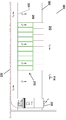
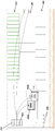
도 5는 저온의 공급 공기로부터 고온의 오버헤드 복귀 공기를 격리하기 위해 수직 차폐판이 사용되는 본 개시의 또 다른 실시예에 따른 데이터 센터 조립체의 입면도이다.
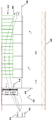
도 6은 열기 통로에서 배출되는 공기가 지면 높이의 냉각 모듈 내로 인입되는 것을 도시한 본 개시의 또 다른 실시예에 따른 데이터 센터 조립체의 입면도이다.
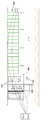
도 7은 서버 랙의 전방으로 저온의 공기를 송풍하는 기술을 도시한 본 개시의 또 다른 실시예에 따른 것으로 데이터 센터 조립체의 입면도이다.
도 8은 냉각 모듈이 오버헤드 위치에 장착된 본 개시의 또 다른 실시예에 따른 데이터 센터 조립체의 입면도이다.
도 9는 냉각 모듈의 위치가 바닥 보다 높은 본 개시의 또 다른 실시예에 따른 데이터 센터 조립체의 입면도이다.
도 10은 냉각 모듈 또는 조립체의 위치가 바닥보다 높은 본 개시의 또 다른 실시예에 따른 데이터 센터 조립체의 입면도이다.
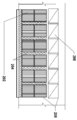
도 11은 본 개시의 일 실시예에 따른 다수의 팬 및 열교환기 모듈을 구비한 팬 및 열교환기 조립체의 입면도이다.
도 12는 본 개시의 일 실시예에 따른 다수의 팬 및 열교환기 모듈을 구비한 팬 및 열교환기 조립체의 정면도이다.
도 13은 본 개시의 일 실시예에 따른 "기초" 함체 조립체의 사시도이다.
도 14는 본 개시의 일 실시예에 따른 "부가" 함체 조립체의 사시도이다.
도 15는 본 개시의 일 실시예에 따른 팬 및 열교환기 조립체의 분해도이다.
도 16은 본 개시의 일 실시예에 따른 팬 및 열교환기 조립체의 팬을 제어하는 예시적인 방법을 도시한 흐름도이다.
도 17은 본 개시의 일 실시예에 따른 풍속계 모듈의 분해도이다.
도 18은 차폐 조립체의 벽에 설치된 도 17의 풍속계 모듈의 측면도이다.
상기 도면은 단지 예시의 목적으로만 본 개시의 실시예를 도시한다. 기술분야의 당업자라면 다음의 설명으로부터 본 명세서에 예시된 구조 및 방법의 대안적인 실시예가 본 명세서에 설명된 본 개시의 원리를 벗어나지 않고 채택될 수 있다는 것을 용이하게 알 수 있을 것이다.One or more aspects of the disclosure are specifically pointed out and explicitly claimed in the claims set forth at the end of the specification. Those skilled in the art will more readily understand the above and other objects, features, and advantages of the present disclosure with reference to the detailed description of various embodiments in which similar elements are provided with the accompanying drawings in which the same reference signs are indicated.
1 is an elevation view of a data center assembly according to one embodiment of the present disclosure with a relatively low ceiling height.
FIG. 2 is a front sectional view of the cooling assembly of FIG. 1 taken along the AA cut line.
3 is an elevational view of a data center assembly according to another embodiment taking the bottom cold air supply method.
4 is an elevational view of a data center assembly according to another embodiment of the present disclosure with a relatively high ceiling height.
5 is an elevation view of a data center assembly according to another embodiment of the present disclosure in which a vertical shield is used to isolate the hot overhead return air from the cold supply air.
6 is an elevational view of a data center assembly according to another embodiment of the present disclosure showing that air exiting the hot air passage is drawn into a ground level cooling module.
7 is an elevation view of a data center assembly in accordance with another embodiment of the present disclosure showing a technique for blowing cold air to the front of a server rack.
8 is an elevational view of a data center assembly according to another embodiment of the present disclosure in which a cooling module is mounted in an overhead position.
9 is an elevation view of a data center assembly according to another embodiment of the present disclosure where the location of the cooling module is higher than the floor.
10 is an elevation view of a data center assembly according to another embodiment of the present disclosure where the location of the cooling module or assembly is higher than the floor.
11 is an elevational view of a fan and heat exchanger assembly with a plurality of fan and heat exchanger modules according to one embodiment of the present disclosure.
12 is a front view of a fan and heat exchanger assembly with a plurality of fan and heat exchanger modules according to one embodiment of the present disclosure.
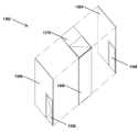
13 is a perspective view of a “base” enclosure assembly according to one embodiment of the present disclosure.
14 is a perspective view of an “additional” enclosure assembly according to one embodiment of the present disclosure.
15 is an exploded view of a fan and heat exchanger assembly according to an embodiment of the present disclosure.
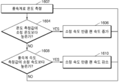
16 is a flow diagram illustrating an exemplary method of controlling a fan of a fan and heat exchanger assembly according to one embodiment of the present disclosure.
17 is an exploded view of an anemometer module according to an embodiment of the present disclosure.
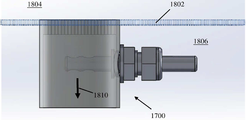
18 is a side view of the anemometer module of FIG. 17 installed on the wall of the shield assembly.
The above drawings illustrate embodiments of the present disclosure for illustrative purposes only. Those skilled in the art will readily appreciate from the following description that alternative embodiments of the structures and methods illustrated herein can be employed without departing from the principles of the present disclosure described herein.
본 개시의 모듈식 공기 냉각 및 분배 시스템은 유연성과 확장성이 우수하고 설치가 용이하며 데이터 센터와 같은 대면적의 개방된 실내 공간의 냉각을 위한 에너지 소비를 저감할 수 있다. 기본적인 팬/열교환기 모듈식 조립체의 조합은 특정 건물의 전체 디자인에 가장 잘 부합하도록 다양한 방식으로 구성될 수 있다.The modular air cooling and distribution system of the present disclosure is excellent in flexibility and scalability, is easy to install, and can reduce energy consumption for cooling of a large area of open indoor space such as a data center. The basic fan / heat exchanger modular assembly combination can be configured in a variety of ways to best suit the overall design of a particular building.
본 개시의 실시예는 고온의 공기를 서버 랙에서 열교환기로 향하게 하는 모듈식 공기 냉각 및 분배 시스템으로, 설치가 용이하고 저렴하며 공기압 손실(air pressure drop)이 작은 모듈식 공기 냉각 및 분배 시스템에 관한 것이다. 이후, 고온의 공기는 액체, 예컨대, 냉매 또는 냉각수로 냉각되어 저온의 공기가 데이터 센터의 개방된 공간으로 다시 배출된다. 실시예에서, 서버에서 배출되는 고온의 공기는 열교환기의 유입구까지 이르는 내내 천장 또는 열기 통로 차폐부와 짧은 도관(필요한 경우)을 이용하여 저온의 공기로부터 격리된다. 고온의 공기를 격리된 상태로 유지함으로써, 열 방출(heat rejection)이 보다 높은 온도에서 이루어질 수 있어서 보다 "자유로운" 냉각이 가능해지고 액체 유량이 저감되며 에너지 효율이 향상된다. 그 전체 내용이 본 명세서에 원용되는 가특허출원 제 62/380,039호에 개시된 바와 같은 것으로, 상기 열교환기는 공기압 손실이 작은 다열 알루미늄 편평관 열교환기이다. 차폐부/천장/플레넘을 통한 작은 공기압 손실과 더불어, 이런 요인은 전체 압력 손실을 저감하고 팬 출력을 낮출 수 있도록 해준다. 분석에 따르면, 몇몇 실시예는 데이터 센터 전체에 걸쳐 균일한 공기 온도 분포를 갖는다.An embodiment of the present disclosure is a modular air cooling and distribution system that directs hot air from a server rack to a heat exchanger, and relates to a modular air cooling and distribution system that is easy to install, inexpensive, and has low air pressure drop. will be. Thereafter, the hot air is cooled with a liquid, such as a refrigerant or cooling water, and the cold air is discharged back to the open space of the data center. In an embodiment, the hot air exiting the server is isolated from the cold air using a ceiling or hot aisle shield and short conduits (if needed) all the way to the inlet of the heat exchanger. By keeping the hot air in isolation, heat rejection can be achieved at higher temperatures, allowing for more “free” cooling, reducing liquid flow and improving energy efficiency. As described in provisional patent application No. 62 / 380,039, the entire contents of which are incorporated herein, the heat exchanger is a multi-row aluminum flat tube heat exchanger with low air pressure loss. In addition to the small air pressure loss through the shield / ceiling / plenum, these factors help to reduce the overall pressure loss and lower the fan output. According to the analysis, some embodiments have a uniform air temperature distribution across the data center.
본 개시에서는 용어 "공기"가 사용되지만, 기체 상태의 다른 유체가 본 개시의 실시예에 따라 공기 대신 사용될 수 있다.Although the term “air” is used in this disclosure, other fluids in gaseous form may be used in place of air in accordance with embodiments of the present disclosure.
도 1 내지 도 10은 팬 및 열교환기 조립체와 기류 배치가 특정 건물 구조의 세부 사항에 맞게 적용될 수 있는 다양한 실시예를 도시한다.1 to 10 show various embodiments in which fan and heat exchanger assembly and airflow arrangement can be applied to the specifics of a particular building structure.
도 1은 비교적 낮은 하부 천장(102)을 갖는 실시예를 도시한다. 냉각 유닛 또는 모듈(104)은 외부에 배치되며 옥내 바닥 공간을 필요로 하지 않는다. 옥외 냉각 모듈 또는 조립체(104)는 공장에서 조립되고 모듈식 슬래브에 장착될 수 있다. 냉각 모듈 또는 조립체(104)는 내후성 함체(enclosure) 내부에 배치될 수 있다. 차폐 조립체(108)가 열기 통로를 포함하도록 서버 랙(110)에 결합된다. 천장 플레넘(112)이 하부 천장(102)과 상부 천장(103) 사이에 한정될 수 있다. 대안으로서, 상부 천장(103)이 제거되고 천장 플레넘(112)이 하부 천장(102)과 경사 지붕(105) 사이에 한정될 수 있다. 천장 플레넘(114)은 냉각 모듈 또는 조립체(104)에 복귀 공기(114)를 공급하도록 구성된다.1 shows an embodiment with a relatively low
중복 구성의 풍속계(150)가 차폐 조립체(108)를 통해 유동하는 공기의 온도 및/또는 속도를 측정하기 위해 차폐 조립체(108)에 결합된다. 다른 실시예에서는, 다른 유형의 유속 센서와 유체 온도 센서가 중복 구성의 풍속계(150) 대신에 사용될 수 있다. 예컨대, 유체 온도 센서는 기계식 스위치에 부착된 패들(paddle)로 대체될 수 있는데, 차폐 조립체(108) 내의 유체 유동으로 인해 패들이 기계식 스위치를 전후로 이동시켜 유체의 유동 방향을 감지하게 된다. 대안으로서, 유체의 유동 방향은 당업계에 공지된 임의의 다른 유체 유동 방향 센서에 의해 측정될 수 있다. 유속 센서는 임의의 적합한 저속형(low velocity-type) 센서일 수 있다.An overlapping
온도 및/또는 속도 측정값은 팬 및 열교환기 조립체의 팬들 중 하나 이상의 팬의 속도를 제어하기 위해 사용된다. 예컨대, 열기 통로와 냉기 통로 사이의 유체 누출율을 나타내는 유체 속도 및 온도 측정값은 팬 및 열 교환기 조립체의 팬의 속도를 조절하여 차폐 조립체 내부의 압력을 중화하기 위해 사용될 수 있다. 실시예에서, 풍속계(150)는 공기의 온도와 속도를 동시에 감지할 수 있는 열선 풍속계일 수 있다.Temperature and / or speed measurements are used to control the speed of one or more of the fans of the fan and heat exchanger assembly. For example, fluid velocity and temperature measurements representing the fluid leak rate between the hot and cold passages can be used to neutralize the pressure inside the shield assembly by adjusting the speed of the fans of the fan and heat exchanger assembly. In an embodiment, the
실시예에서, 제어 시스템은 온도 설정점과 속도 설정점을 이용할 수 있다. 예컨대, 온도 설정점은 하기 식에 따라 산출될 수 있다.In embodiments, the control system may utilize temperature setpoints and speed setpoints. For example, the temperature set point can be calculated according to the following equation.
온도 설정점 = 열기 통로 온도 - {(열기 통로 온도 - 냉기 통로 설정 온도)/ 3}.Temperature setpoint = hot aisle temperature-{(hot aisle temperature-cold aisle set temperature) / 3}.
온도 설정점은 팬 및 열교환기 조립체의 팬에게 가속 또는 감속을 명령하기 위해 사용된다. 속도 설정점은 팬 속도를 미세 조정하여 공기 누출을 최소화하기 위해 사용될 수 있다. 예컨대, 속도 설정점은 팬을 감속하기 위해 사용될 수 있다.The temperature setpoint is used to command acceleration or deceleration to the fans of the fan and heat exchanger assembly. The speed setpoint can be used to fine-tune the fan speed to minimize air leakage. For example, the speed setpoint can be used to decelerate the fan.
제어 시스템은 수동 모드와 자동 모드로 동작할 수 있다. 수동 모드에서는, 팬이 자동 설정에 우선하는 고정 속도로 설정된다. 예컨대, 초기 속도 설정점은 소정의 속도, 예컨대, 45.72 m/분(150 ft/분)로 설정될 수 있다. 자동 모드에서는, 저 부하가 인가될 경우, 제어 시스템이 먼저 열기 통로 및 냉기 통로 설정 온도가 예컨대, 소정의 온도, 예컨대, -15℃(5℉) 미만인지를 판단할 수 있다. 열기 통로 및 냉기 통로 설정 온도가 -15℃(5℉) 미만일 경우, 팬 속도는 소정의 최저 속도일 수 있는 최저 속도로 유지된다. 산출된 총 IT 부하를 기능 중인 팬 및 열교환기 조립체의 총 개수로 나눈 값이 소정의 백분율(예컨대, 30%) 미만이거나 팬 및 열 교환기 조립체의 유입 온도와 배출 온도 사이의 온도 차가 소정의 온도(예컨대, -12.2℃(10℉)) 미만일 경우, 팬 속도는 하기 예시적인 방정식에 따라 산출될 수 있다.The control system can operate in manual mode and automatic mode. In manual mode, the fan is set at a fixed speed that overrides the automatic setting. For example, the initial speed set point may be set at a predetermined speed, for example, 45.72 m / min (150 ft / min). In the automatic mode, when a low load is applied, the control system can first determine whether the hot and cold air passage set temperatures are less than, for example, a predetermined temperature, eg, -15 ° C (5 ° F). If the hot aisle and cold aisle set temperature is less than -15 ° C (5 ° F), the fan speed is maintained at the lowest speed, which may be a predetermined lowest speed. The calculated total IT load divided by the total number of functional fan and heat exchanger assemblies is less than a predetermined percentage (e.g., 30%), or the temperature difference between the inlet and outlet temperatures of the fan and heat exchanger assembly is a given temperature ( For example, below -12.2 ° C (10 ° F), the fan speed can be calculated according to the following exemplary equation.
![]()
![]()
산출된 총 IT 부하를 기능 중인 팬 및 열 교환기 조립체의 총 개수로 나눈 값이 소정의 백분율(예컨대, 30%)보다 크고 팬 및 열 교환기 조립체의 유입 온도와 배출 온도 사이의 온도 차가 소정의 온도(예컨대, -12.2℃(10℉)보다 클 경우, 최대 팬 속도 대비 백분율은 하기와 같이 결정될 수 있다. 풍속계의 측정값이 온도 설정점(예컨대, -12.2℃(10℉))보다 높을 경우에는, 팬 속도가 소정의 분당 회전수(RPM)(예컨대, 100 RPM)만큼 증가된다. 감지된 온도가 온도 설정점 미만이 될 때까지 팬 속도는 계속 증가한다. 풍속계의 온도 측정값이 온도 설정점보다 낮고 풍속계의 속도 측정값이 속도 설정점(예컨대, 45.72 m/분(150 ft/분))보다 클 경우에는, 팬 속도가 감소된다(예컨대, 팬 속도가 100 RPM 만큼 감소되거나 속도 제어용 PID 제어기가 풍속계의 측정값에 기초하여 적용된다).The calculated total IT load divided by the total number of functional fan and heat exchanger assemblies is greater than a certain percentage (e.g., 30%), and the temperature difference between the inlet and outlet temperatures of the fan and heat exchanger assembly is a given temperature ( For example, if greater than -12.2 ° C (10 ° F), the percentage of the maximum fan speed can be determined as follows: If the anemometer reading is higher than the temperature setpoint (eg, -12.2 ° C (10 ° F)), The fan speed is increased by a certain number of revolutions per minute (RPM) (eg 100 RPM) The fan speed continues to increase until the detected temperature is below the temperature set point The temperature measurement of the anemometer is above the temperature set point If it is low and the speed measurement of the anemometer is greater than the speed setpoint (e.g. 45.72 m / min (150 ft / min)), the fan speed is reduced (e.g., the fan speed is reduced by 100 RPM or the PID controller for speed control) Applied based on measured values of anemometer do).
풍속계의 온도 측정값이 온도 설정점보다 낮고 풍속계의 속도 측정값이 예컨대, 현장 조건에 따라 달라질 수 있는 속도 설정점(예컨대, 22.86 m/분(75 ft/분) 또는 45.72 m/분(150 ft/분))보다 낮을 경우, 팬 속도는 변경되지 않는다. 몇몇 실시예에서, 풍속계의 온도 측정값이나 속도 측정값이 변동이 심할 경우, 제어기는 순간 측정값 대신 일정 시간 동안의(예컨대 3초 내지 5초 동안의) 평균 측정값을 적용할 수 있다.Speed setpoints (eg, 22.86 m / min (75 ft / min) or 45.72 m / min (150 ft) where the anemometer's temperature reading is lower than the temperature setpoint and the anemometer's speed reading may vary depending on, for example, site conditions / Min)), the fan speed will not change. In some embodiments, if the anemometer's temperature or velocity measurements fluctuate heavily, the controller may apply average measurements over a period of time (eg, for 3 to 5 seconds) instead of instantaneous measurements.
도 2는 일 실시예에 따른 것으로 A-A 절단선을 따라 취한 선택적 모듈식 공기 벽 구간의 단면도이다. 모듈식 공기 벽 구간은 가로 6 열 세로 2 열로 배열된 12 개의 팬 및 열교환기 모듈 또는 조립체에 대응하는 12 개의 가드(guard) 또는 루버(louvre) 구간(202)을 포함한다. 즉, 가드 또는 루버 구간(202)은 각각 6 개의 팬 및 열 교환기 조립체로 구성된 팬 및 열 교환기 조립체 2 열에 대응한다. 실시예에서, 데이터 센터의 용량 요건 및/또는 구성에 따라 임의의 개수의 팬 및 열교환기 조립체 열이 구비될 수 있다. 예를 들어, 3 열의 팬 및 열교환기 조립체가 구비되거나 7 열의 팬 및 열교환기 조립체가 구비될 수 있다. 각각의 가드 또는 루버 섹션(202)은 유체를 특정 방향으로 향하게 하거나 유체를 소정 각도로 확산시키는 유체 편향기를 포함할 수 있다. 유체 편향기의 각도는 조절 가능할 수 있다.2 is a cross-sectional view of an optional modular air wall section taken along the A-A cut line, according to one embodiment. The modular air wall section includes twelve guard or
기계 및 전기식 체이스(chase)(204)가 가드 또는 루버 섹션(202) 사이에 배치되고 팬 및 열교환기 조립체의 팬 및/또는 열교환기 사이에 배치될 수 있다. 벽 개방부 또는 개구부(206)가 복귀 공기 도관(208)과 가드 또는 루버 섹션(202)을 수납하기 위해 형성된다. 실시예에서, 복귀 공기 도관(208)은 서로 결합되어, 플레넘 룸(106)으로 들어가는 단일 또는 공통 복귀 공기 도관을 형성할 수 있다. 모듈식 공기 벽 구간은, 추가적인 냉각 용량이 필요할 경우 천장 플레넘(112)에서 플레넘 룸(106)으로 보다 많은 복귀 공기를 전달하는 추가 유체 도관을 수납하기 위해 탈착될 수 있는 탈부착 가능 복귀 공기 패널(208)도 포함한다.Mechanical and
도 3은 바닥 냉기 공급(under-floor cool air distribution) 방식을 취하는 예시적인 데이터 센터 조립체의 실시예를 도시한다. 복귀 공기(214)는 천장(302)과 지붕(303) 사이의 천장 플레넘과, 철망 스크린(330)을 구비한 팬 및 열교환기 조립체와, 슬래브(322)와 천공형 바닥 타일(324) 사이에 형성된 용적부와, 서버 랙(210)을 순차적으로 통과하며 순환된다.3 shows an embodiment of an exemplary data center assembly that takes an under-floor cool air distribution scheme. The return air 214 is between the ceiling plenum between the
도 4는 다층 건물의 다른 층에 대응될 수 있는 비교적 높은 천장(403)을 갖는 냉기 통로 차폐 구성을 취하는 예시적인 데이터 센터 조립체의 실시예를 도시한다. 실시예에서, 높은 천장(403)은 천장 플레넘(412)의 일부를 형성할 수 있는 T형 콘크리트 보로 형성될 수 있다. 실시예에서, 높은 천장(403)은 낮은 천장(402)에 보다 가깝도록 설치될 수 있다. 수직 차폐판(431)이 저온의 공급 공기(413)로부터 고온의 복귀 공기(414)를 격리시킨다. 팬 배출 공기 유동이 역전되고 냉기(413)가 서버 랙(210)에 의해 형성되는 냉기 통로를 포함하는 차폐 조립체(408)를 통해 서버 랙(210)의 전방으로 공급된다. 또한, 고온의 공기(414)가 팬 및 열교환기 조립체의 팬에 의해 서버 랙(210)의 하나 이상의 열기 통로로부터 인출된다. 제어 모듈(432)과 전력 모듈(434)이 차폐 조립체(408)와 팬 및 열 교환기 조립체 내를 유동하는 유체와 유체 연통되는 풍속계(150)에 결합되어 차폐 조립체(408)와 팬 및 열 교환기 조립체에 제어 신호와 전력을 각각 공급한다. 여기서, 제어 신호는 예컨대, 팬 및 열교환기 조립체의 가변 속도 팬의 속도를 제어하기 위한 제어 신호일 수 있다. 제어 모듈(431)은 유체 온도 및 속도 측정값을 사용하는 방법을 포함하는 본 명세서에 개시된 방법을 실행하기 위한 프로세서와 메모리를 포함할 수 있는 임의의 적합한 제어기로 구현될 수 있다. 4 shows an embodiment of an exemplary data center assembly taking a cold aisle shield configuration with a relatively
도 5는 수직 차폐판(431)이 저온의 공급 공기(513)로부터 고온의 오버헤드 복귀 공기(514)를 격리하기 위해 사용되는 열기 통로 차폐 구성을 취하는 예시적인 데이터 센터 조립체의 실시예를 도시한다. 팬 배출 공기 유동(저온의 공급 공기(513))의 방향은 도 4의 팬 배출 공기 유동(고온의 복귀 공기(414))의 방향과 반대이다. 팬 및 열교환기 조립체의 팬은 서버 랙(210)의 전방으로 저온의 공급 공기(513)를 공급한다. 또한, 고온의 복귀 공기(514)는 차폐 조립체(508)로부터 흘러 나온다.FIG. 5 shows an embodiment of an exemplary data center assembly in which a vertical shield plate 431 takes the hot aisle shield configuration used to isolate the hot
도 6은 서버 랙(210)의 열기 통로에서 나오는 고온의 복귀 공기(414)가 지면 높이의 외부 팬 및 열교환기 조립체 내로 인입되는 냉각 시스템의 실시예를 도시한다. 저온의 공급 공기(413)가 오버헤드 위치로부터 서버 랙(210)의 전방으로 공급된다. 서버 랙(210) 사이의 하나 이상의 열기 통로가 서버 랙(210)의 최상부 또는 상단에서 커버로 둘러싸이고, 열기 차폐 조립체(608)가 서버 랙들(210) 중 최우측 서버 랙과 건물 또는 시설의 벽 또는 패널(632) 사이에 배치된다. 열기 차폐 조립체(608)는 외부의 팬 및 열교환기 조립체와 기류 연통된다.FIG. 6 shows an embodiment of a cooling system in which
도 7은 저온의 공급 공기(713)가 서버 랙(210)의 전방으로 송풍되는 냉각 시스템의 실시예를 도시한다. 오버헤드 열기 통로 차폐 조립체가 서버 랙(210)에서 팬 및 열교환기 조립체(720)의 유입구로 고온의 복귀 공기(714)를 이동시키기 위해 사용된다.7 shows an embodiment of a cooling system in which
도 8은 팬 및 열교환기 조립체(820a, 820b)가 오버헤드 위치에 장착된 냉각 시스템의 실시예를 도시한다. 도 8의 냉각 시스템은 제1 공기 차폐 조립체(807)와 제1 공기 차폐 조립체(807) 상에 배치되는 제2 공기 차폐 조립체(808)를 포함한다. 팬 및 열교환기 조립체(820a, 820b)는 제2 공기 차폐 조립체(808)의 최우측부의 밑면에 계단식으로 결합되고 제2 공기 차폐 조립체(808)와 기류 연통된다. 팬 및 열 교환기 조립체(820a, 820b)의 열교환기는 수냉 시스템으로부터 냉각수를 공급 받고 수냉 시스템으로 냉각수를 복귀시키도록 냉각수 공급 및 회수 배관(840)에 결합된다. 팬 및 열교환기 조립체(820a, 820b)는 팬 및 열교환기 조립체(820a, 820b)에 전력과 제어 신호를 각각 공급하는 전력 모듈(434)과 제어 모듈(432)에 결합된다.8 shows an embodiment of a cooling system in which the fan and
도 9는 팬 및 열교환기 조립체(920)의 위치가 바닥(950)보다 높은 다른 실시예를 도시한다. 고온의 복귀 공기가 바닥(950) 높이에서 서버 랙(210)에 의해 형성된 열기 통로로부터 인출되고, 저온의 공급 공기(913)가 위로부터 서버 랙(210)의 전방으로 하향 공급된다. 차폐 조립체(908)가 최우측 서버 랙(910)과 팬 및 열교환기 조립체(920)의 밑면에 결합된다. 이 구성에서, 팬 및 열교환기 조립체의 팬은 차폐 조립체(908)를 통해 서버 랙(210)의 열기 통로로부터 고온의 공기(914)를 인출한다.9 shows another embodiment where the position of the fan and
도 10은 팬 및 열교환기 조립체(920)의 위치가 바닥(950)보다 높은 냉각 시스템의 다른 실시예를 도시한다. 본 냉각 시스템은 제1 공기 차폐 조립체(1007)와 제1 공기 차폐 조립체(1007)의 상단에 결합되고 제1 공기 차폐 조립체(1007)와 기류 연통되는 제2 공기 차폐 조립체(1008)를 포함한다. 팬 및 열교환기 조립체(920)는 제2 공기 차폐 조립체(1008)의 최우측부(1009)의 밑면에 결합되고 제2 공기 차폐 조립체(1008)와 기류 연통된다. 팬 및 열교환기 조립체(920)의 열교환기는 수냉 시스템에서 배출되는 냉각수를 전달하고 수냉 시스템으로 복귀하는 물을 전달하는 냉각수 공급 및 회수 배관에 연결된다. 팬 및 열교환기 모듈의 팬은 전력과 제어 신호를 팬에 공급하는 전력 및 제어 모듈에 결합된다. 고온의 복귀 공기가 제2 공기 차폐 구조로부터 인출되어 오버헤드 플레넘으로 이동되고, 저온의 공급 공기가 서버 랙의 전방 주위로 송풍된다.10 shows another embodiment of a cooling system in which the position of the fan and
도 11 및 도 12는 보다 큰 팬 및 열교환기 조립체를 형성하도록 조립된 예시적인 팬 및 열교환기 모듈 또는 조립체의 측면도와 정면도를 각각 도시한다. 실시예에서, 2 개, 3 개 또는 4 개의 팬 및 열교환기 조립체가 적층되어 팬 및 열교환기 조립체 적층체(1102,1104 또는 1106)를 형성할 수 있다. 실시예에서, 임의의 개수의 팬 및 열교환기 조립체 적층체(1102,1104 또는 1106)가 나란히 연결될 수 있다. 예를 들어, 6 개의 적층체가 나란히 연결될 수 있다.11 and 12 show side and front views, respectively, of an exemplary fan and heat exchanger module or assembly assembled to form a larger fan and heat exchanger assembly. In an embodiment, two, three or four fan and heat exchanger assemblies may be stacked to form a fan and heat
도 13은 예컨대, 그 폭이 하나의 팬 및 열 교환기 모듈에 대응되고 그 높이가 두 개의 팬 및 열 교환기 모듈에 대응될 수 있는 예시적인 "기초(starter) 함체 조립체"(1302)를 도시한다. 기초 함체 조립체(1302)는 좌측 벽 패널(1304)과, 우측 벽 패널(1306)과, 후방 벽 패널(1308)과, 지붕 패널(1310)을 포함한다. 좌측 벽 패널(1304)과 우측 벽 패널(1306)은 팬 및 열교환기 모듈 또는 조립체 적층체에 접근하기 위한 접근 도어(1308)를 포함할 수 있다.FIG. 13 shows an exemplary “starter enclosure assembly” 1302, for example, whose width corresponds to one fan and heat exchanger module and its height can correspond to two fan and heat exchanger modules. The
도 14는 예컨대, 그 폭이 하나의 팬 및 열 교환기 모듈에 대응되고 그 높이가 두 개의 팬 및 열 교환기 모듈에 대응될 수 있는 예시적인 "부가(add-on) 함체 조립체"(1402)를 도시한다. 부가 함체 조립체(1402)는 도 13의 기초 함체 조립체(1302)에 부착될 수 있는 좌측 벽 패널(1304) 후방 벽 패널(1308) 및 지붕 패널(1310)을 포함한다.FIG. 14 shows an exemplary “add-on enclosure assembly” 1402, for example, whose width may correspond to one fan and heat exchanger module and its height may correspond to two fan and heat exchanger modules. do. The
도 15는 기초 조립체(1302)와, 부가 조립체(1402)와, 기초 함체 조립체(1302) 및 부가 함체 조립체(1402) 내에 포함되는 팬 및 열교환기 모듈 또는 조립체 적층체를 도시하는 분해도이다. 팬 및 열교환기 조립체 적층체(1501)는 팬 가드(1502)(예컨대, 3 개의 팬 가드)와, 가변 속도 팬(1504)(예컨대, 3 개의 가변 속도 팬)과, 팬 하우징(1506)(예컨대, 서로 결합되도록 구성되는 3 개의 팬 하우징)과, 열교환기(1508)(예컨대, 서로 결합되도록 구성되는 3 개의 열교환기)를 포함한다. 함체 조립체(1302, 1402)와 팬 및 열교환기 조립체 적층체(1501)는 부분적으로 조립된 키트 형태로 배송될 수 있다. 이후, 최종 조립이 현장에서 이루어질 수 있다.FIG. 15 is an exploded view showing a
열기 통로 차폐 구역 또는 조립체로부터의 공기 유량이 특정 값을 갖도록 보장하기 위해 열선 풍속계를 사용하여 팬의 속도를 서버 공기 유동에 부합하도록 제어할 수 있다. 도 16은 본 개시의 실시예에 따른 것으로, 팬 및 열교환기 조립체의 팬을 제어하는 예시적인 방법을 도시한 흐름도이다. 블록 1602에서는, 풍속계를 사용하여 온도를 측정한다. 이어서 블록 1604에서는, 측정된 온도가 소정의 온도, 예컨대, 26.7℃(80℉)보다 높은지 판정한다. 측정된 온도가 소정의 온도보다 높을 경우, 블록 1606에서, 팬 속도를 소정의 속도, 예컨대, 100 RPM 만큼 증가시킨다.To ensure that the air flow from the hot aisle containment area or assembly has a specific value, a hot wire anemometer can be used to control the fan's speed to match the server air flow. 16 is a flow diagram illustrating an exemplary method of controlling a fan of a fan and heat exchanger assembly, in accordance with an embodiment of the present disclosure. In
측정된 온도가 소정의 온도 이하일 경우, 블록 1608에서, 풍속계의 속도 측정값이 소정의 속도, 예컨대, 45.72 m/분(150 ft/분)보다 큰지 판정한다. 풍속계의 속도 측정값이 소정의 속도보다 클 경우, 블록 1610에서, 팬 속도를 소정의 속도 또는 다른 소정의 속도까지 감소시킨다. 풍속계의 속도 측정값이 소정의 속도 이하일 경우, 블록 1602로 되돌아가 풍속계로 온도를 측정한다.If the measured temperature is below a predetermined temperature, at
도 17은 본 개시의 일 실시예에 따른 것으로, 유체 속도 및 유체 온도를 측정하기 위해 사용되는 풍속계 모듈(1700)의 분해도이다. 풍속계 모듈(1700)은 풍속계 하우징(1702)과, 풍속계 유지부(1704)와, 하우징 너트 유지부(1706)와, 풍속계(1708)와, 풍속계 너트 유지부(1710)를 포함한다. 풍속계 유지부(1704)는 하우징 너트 유지부(1706)를 이용하여 풍속계 하우징(1702)에 고정된다. 풍속계(1708)는 풍속계(1708)의 2 개의 측정창이 풍속계 하우징(1704)의 중심에 위치하고 도 18에 도시된 유체 유동 방향(1810)에 수직하도록 풍속계 유지부(1704)에 삽입된다. 풍속계(1708)는 풍속계 너트 유지부(1710)에 의해 적소에 고정된다.17 is an exploded view of an
도 18에 도시된 바와 같이, 도 17의 풍속계 모듈(1700)은 풍속계 하우징(1702)의 벌집 측이 냉기 통로(1804)로부터 열기 통로(1806)를 격리시키는 차폐 조립체 벽(1802)과 동일 평면 상에 있도록 차폐 조립체 벽(1802)의 절개부(cutout)에 설치된다. 벌집 구조는 유체가 일직선으로 유동하도록 하여 난류를 저감하고 풍속계의 정확도를 높이는 데 도움이 된다.As shown in FIG. 18, the
열교환기 내의 액체(예컨대, 글리콜과 물) 유동은 소기의 공기 배출 온도를 유지하도록 조절될 수 있다. 두 개 이상의 모듈을 사용할 경우의 기계적 중복 구성 외에도, 전체 시스템은 임의의 적합한 통신 네트워크를 경유한 제어를 위해 네트워크 중복 구성을 이용한다.The flow of liquid (eg, glycol and water) in the heat exchanger can be adjusted to maintain the desired air exhaust temperature. In addition to mechanical redundancy when using two or more modules, the entire system uses network redundancy for control via any suitable communication network.
그 전체 내용이 본 명세서에 원용되는 것으로 발명의 명칭이 "단상 유체와 역류 회로를 구비한 편평관 열교환기를 이용한 냉각 시스템 및 방법{Cooling Systems and Methods Using Single-Phase Fluid and a Flat Tube Heat Exchanger with Counter-Flow Circuiting}"이고 2017년 8월 28일에 출원된 국제 출원 제PCT/US2017/048969 호에 개시된 열교환기의 실시예를 포함하여, 임의의 적합한 열 교환기 설계가 본 개시의 실시예에 사용될 수 있다.Cooling systems and methods using a single-phase fluid and a flat tube heat exchanger with a counter having a single-phase fluid and a back-flow circuit -Flow Circuiting} and any suitable heat exchanger design can be used in the embodiments of the present disclosure, including embodiments of the heat exchanger disclosed in International Application PCT / US2017 / 048969 filed August 28, 2017. have.
그 전체 내용이 본 명세서에 원용되는 것으로 발명의 명칭이 "단상 유체를 이용한 냉각 시스템 및 방법{Cooling Systems and Methods Using Single-Phase Fluid"인 미국 특허 출원 제 15/697445호에 개시된 유체 쿨러/칠러를 포함하여, 액체와 같은 임의의 적합한 유체를 공급하는 임의의 적합한 유체 쿨러/칠러가 본 개시의 실시예에 따른 팬 및 열교환기 조립체의 열교환기에 사용될 수 있다.The fluid cooler / chiller disclosed in U.S. Patent Application No. 15/697445, entitled " Cooling Systems and Methods Using Single-Phase Fluid, " Including any suitable fluid cooler / chiller that supplies any suitable fluid, such as liquid, can be used in the heat exchanger of a fan and heat exchanger assembly according to embodiments of the present disclosure.
본 개시의 실시예를 첨부 도면을 참조하여 설명하였으나, 기술분야의 당업자라면 이에 대한 다양한 변경 및 수정을 명백히 알 수 있을 것이다. 이런 변경 및 수정은 첨부된 특허청구범위에서 정하는 본 개시의 범위 내에 포함되는 것으로 이해해야 한다.Although embodiments of the present disclosure have been described with reference to the accompanying drawings, those skilled in the art will clearly appreciate various changes and modifications thereto. It should be understood that such changes and modifications are included within the scope of the present disclosure as defined by the appended claims.
102: 하부 천장
103: 상부 천장
104: 냉각 모듈
105: 경사 지붕
106: 플레넘 룸
108, 408, 508, 608, 908: 차폐 조립체
110, 210: 서버 랙
112, 312: 천장 플레넘
114, 414, 514, 714, 914: 복귀 공기
150: 풍속계
202: 루버 구간
204: 체이스
206: 벽 개구부
208: 복귀 공기 도관
210: 서버 랙
302: 천장
303: 지붕
322: 슬래브
324: 바닥 타일
330: 철망 스크린
402: 낮은 천장
413, 513, 713, 913: 공급 공기
431: 수직 차폐판
432: 제어 모듈
434: 전력 모듈
720, 820a, 820b, 920: 팬 및 열교환기 조립체
807, 1007: 제1 공기 차폐 조립체
808, 1008: 제2 공기 차폐 조립체
840: 냉각수 공급 및 회수 배관
950: 바닥
1102, 1104, 1106, 1501: 팬 및 열교환기 조립체 적층체
1302: 기초 함체 조립체
1304: 좌측 벽 패널
1306: 우측 벽 패널
1308: 후방 벽 패널
1310: 지붕 패널
1402: 부가 함체 조립체
1502: 팬 가드
1504: 가변속도 팬
1506: 팬 하우징
1508: 열교환기
1700: 풍속계 모듈
1702: 풍속계 하우징
1704: 풍속계 유지부
1706: 하우징 너트 유지부
1708: 풍속계
1710: 풍속계 너트 유지부
1802: 차폐 조립체 벽
1804: 냉기 통로
1806: 열기 통로102: lower ceiling 103: upper ceiling 104: cooling module
105: slope roof 106: plenum room
108, 408, 508, 608, 908:
112, 312:
150: anemometer 202: louver section 204: chase
206: wall opening 208: return air conduit 210: server rack
302: ceiling 303: roof 322: slab
324: floor tile 330: wire screen 402: low ceiling
413, 513, 713, 913: Supply air 431: Vertical shield
432: control module 434: power module
720, 820a, 820b, 920: fan and heat exchanger assembly
807, 1007: first
840: cooling water supply and return pipe 950: floor
1102, 1104, 1106, 1501: fan and heat exchanger assembly stack
1302: Foundation enclosure assembly 1304: Left wall panel
1306: right wall panel 1308: rear wall panel 1310: roof panel
1402: additional housing assembly 1502: fan guard 1504: variable speed fan
1506: fan housing 1508: heat exchanger 1700: anemometer module
1702: Anemometer housing 1704: Anemometer holding part
1706: housing nut holding portion 1708: anemometer
1710: Anemometer nut holding 1802: Shield assembly wall
1804: Cold passage 1806: Hot passage
Claims (21)
각각 복수의 서버 랙으로 구성되는 복수의 서버 랙 열에 의해 형성되는 적어도 하나의 열기 통로 상부에 배치되고 상기 제1 천장의 개구부를 통해 연장되되 유체를 상기 열기 통로에서 상기 천장 플레넘 내로 향하게 하도록 구성되는 차폐 조립체와,
상기 열기 통로 또는 상기 차폐 조립체 내를 유동하는 유체의 속도를 측정하도록 구성되는 유속 센서와,
상기 열기 통로 또는 상기 차폐 조립체 내를 유동하는 유체의 온도를 측정하도록 구성되는 온도 센서와,
적어도 하나의 팬 및 열교환기 조립체와,
측정된 온도 및 속도에 기초하여 상기 적어도 하나의 팬 및 열교환기 조립체의 적어도 하나의 팬의 속도를 조절하도록 구성되는 제어기를 포함하되,
상기 적어도 하나의 팬 및 열교환기 조립체의 적어도 하나의 팬은 유체를 상기 적어도 하나의 팬 및 열교환기 조립체의 적어도 하나의 열교환기를 통해 상기 천장 플레넘에서 상기 복수의 서버 랙으로 유동시키는 냉각 시스템.A ceiling plenum formed between the first and second ceilings of the building,
Disposed on top of at least one hot air passage formed by a plurality of server rack rows each comprising a plurality of server racks and extending through an opening in the first ceiling, configured to direct fluid from the hot air passage into the ceiling plenum A shield assembly,
A flow rate sensor configured to measure the velocity of the fluid flowing in the hot air passage or the shield assembly;
A temperature sensor configured to measure a temperature of a fluid flowing in the hot air passage or the shield assembly,
At least one fan and heat exchanger assembly,
A controller configured to adjust the speed of the at least one fan and at least one fan of the heat exchanger assembly based on the measured temperature and speed,
The cooling system for the at least one fan and at least one fan of the heat exchanger assembly to flow fluid from the ceiling plenum to the plurality of server racks through at least one heat exchanger of the at least one fan and heat exchanger assembly.
상기 건물의 바닥과 슬래브 사이에 형성되는 바닥 플레넘과,
상기 천장 플레넘과 상기 바닥 플레넘 사이에 유체 연통되도록 결합되는 공기 도관을 추가로 포함하되,
상기 적어도 하나의 팬 및 열교환기 조립체는 상기 공기 도관 내에 배치되고 공기를 상기 공기 도관을 통해 상기 바닥 플레넘으로 유동시키고 상기 바닥의 개구부를 통해 상기 복수의 서버 랙으로 유동시키도록 구성되는 냉각 시스템.According to claim 1,
A floor plenum formed between the floor and the slab of the building,
Further comprising an air conduit coupled to be in fluid communication between the ceiling plenum and the floor plenum,
The at least one fan and heat exchanger assembly is disposed within the air conduit and is configured to flow air through the air conduit to the floor plenum and to flow through the openings in the floor to the plurality of server racks.
상기 제1 차폐 조립체 내를 유동하는 유체의 속도를 측정하도록 구성되는 유속 센서와,
상기 제1 차폐 조립체 내를 유동하는 유체의 온도를 측정하도록 구성되는 온도 센서와,
상기 건물 외부에 배치되는 복수의 팬 및 열교환기 조립체로 구성된 제1 팬 및 열교환기 조립체 열과,
상기 제1 팬 및 열교환기 조립체 열에 인접하게 상기 건물 외부에 배치되는 복수의 팬 및 열교환기 조립체로 구성된 제2 팬 및 열교환기 조립체 열과,
측정된 온도 및 속도에 기초하여 상기 제1 및 제2 팬 및 열 교환기 조립체 열의 복수의 팬의 속도를 조절하도록 구성되는 제어기를 포함하되,
상기 팬 및 열 교환기 조립체의 복수의 팬은 공기를 상기 제1 차폐 조립체를 통해 열기 통로로부터 유동시키고 상기 복수의 팬 및 열교환기 조립체의 복수의 열교환기를 통해 상기 복수의 서버 랙으로 유동시키는 냉각 시스템.A first shielding assembly disposed inside the building adjacent to at least one hot air passage formed by a plurality of server rack rows each composed of a plurality of server racks,
A flow rate sensor configured to measure the velocity of the fluid flowing in the first shield assembly;
A temperature sensor configured to measure a temperature of a fluid flowing in the first shielding assembly,
A first fan and heat exchanger assembly row composed of a plurality of fan and heat exchanger assemblies disposed outside the building;
A second fan and heat exchanger assembly row composed of a plurality of fan and heat exchanger assemblies disposed outside the building adjacent to the first fan and heat exchanger assembly row;
A controller configured to adjust the speeds of the plurality of fans of the first and second fan and heat exchanger assembly rows based on the measured temperature and speed,
A cooling system for the plurality of fans of the fan and heat exchanger assembly to flow air from the hot air passage through the first shield assembly and through the plurality of heat exchangers of the plurality of fan and heat exchanger assembly to the plurality of server racks.
상기 차폐 조립체 내를 유동하는 유체의 속도를 측정하도록 구성되는 유속 센서와,
상기 차폐 조립체 내를 유동하는 유체의 온도를 측정하도록 구성되는 온도 센서와,
상기 복수의 서버 랙의 최상부보다 위에 위치하도록 상기 건물 내부에 배치되는 각각 복수의 팬 및 열교환기 조립체로 구성되는 제1 및 제2 팬 및 열교환기 조립체 열과,
측정된 온도 및 속도에 기초하여 상기 제1 및 제2 팬 및 열 교환기 조립체 열의 복수의 팬의 속도를 조절하도록 구성되는 제어기를 포함하되,
상기 복수의 팬 및 열교환기 조립체의 복수의 팬은 공기를 상기 제1 차폐 조립체를 통해 상기 열기 통로로부터 유동시키고 상기 팬 및 열교환기 조립체의 복수의 열교환기를 통해 상기 복수의 서버 랙으로 유동시키는 냉각 시스템.A first shielding assembly disposed inside the building adjacent to at least one hot air passage formed by a plurality of server rack rows each composed of a plurality of server racks;
A flow rate sensor configured to measure the velocity of the fluid flowing in the shield assembly,
A temperature sensor configured to measure the temperature of the fluid flowing in the shield assembly,
First and second fan and heat exchanger assembly rows each comprising a plurality of fan and heat exchanger assemblies disposed inside the building so as to be positioned above the top of the plurality of server racks;
A controller configured to adjust the speeds of the plurality of fans of the first and second fan and heat exchanger assembly rows based on the measured temperature and speed,
The plurality of fans and the plurality of fans of the heat exchanger assembly cool the system to flow air from the hot air passage through the first shielding assembly and through the plurality of heat exchangers of the fan and heat exchanger assembly to the plurality of server racks. .
복수의 서버 랙으로 각각 구성된 복수의 서버 랙 열 사이에 한정되는 적어도 하나의 열기 통로 내부 또는 그 부근의 유체 온도를 감지하는 단계와,
상기 유체 온도가 소정의 유체 온도보다 높을 경우, 상기 복수의 서버 랙과 상기 열기 통로와 열교환기를 통해 유체를 순환시키는 적어도 하나의 팬의 속도를 소정의 속도 만큼 증가시키는 단계와,
상기 유체 온도가 소정의 유체 온도보다 낮을 경우, 유체 속도를 측정하고 상기 유체 속도가 소정의 속도보다 높은지 판정하는 단계와,
측정된 유체 속도가 상기 소정의 속도보다 높을 경우, 상기 팬의 속도를 다른 소정의 속도 만큼 감소시키는 단계를 포함하는 서버 랙 냉각 방법.As a method of cooling a plurality of server racks,
Sensing a fluid temperature in or near at least one hot air passage defined between a plurality of server rack rows each composed of a plurality of server racks;
When the fluid temperature is higher than a predetermined fluid temperature, increasing the speed of at least one fan circulating the fluid through the plurality of server racks, the hot air passage and the heat exchanger by a predetermined speed,
If the fluid temperature is lower than a predetermined fluid temperature, measuring a fluid velocity and determining whether the fluid velocity is higher than a predetermined velocity;
And if the measured fluid velocity is higher than the predetermined velocity, reducing the speed of the fan by another predetermined velocity.
Applications Claiming Priority (3)
| Application Number | Priority Date | Filing Date | Title |
|---|---|---|---|
| US201762532680P | 2017-07-14 | 2017-07-14 | |
| US62/532,680 | 2017-07-14 | ||
| PCT/US2018/042353 WO2019014685A1 (en) | 2017-07-14 | 2018-07-16 | Modular air cooling and distribution systems and methods |
Publications (1)
| Publication Number | Publication Date |
|---|---|
| KR20200038477A true KR20200038477A (en) | 2020-04-13 |
Family
ID=63104058
Family Applications (1)
| Application Number | Title | Priority Date | Filing Date |
|---|---|---|---|
| KR1020207004277A KR20200038477A (en) | 2017-07-14 | 2018-07-16 | Modular air cooling and distribution system and method |
Country Status (8)
| Country | Link |
|---|---|
| US (1) | US20200229323A1 (en) |
| EP (1) | EP3653029A1 (en) |
| JP (1) | JP2020527800A (en) |
| KR (1) | KR20200038477A (en) |
| AU (2) | AU2018301734A1 (en) |
| CA (1) | CA3072888A1 (en) |
| SG (1) | SG11202001381UA (en) |
| WO (1) | WO2019014685A1 (en) |
Cited By (1)
| Publication number | Priority date | Publication date | Assignee | Title |
|---|---|---|---|---|
| WO2023149742A1 (en) * | 2022-02-03 | 2023-08-10 | 엘지전자 주식회사 | Composite coating film, heat exchanger comprising same, and method for manufacturing heat exchanger |
Families Citing this family (3)
| Publication number | Priority date | Publication date | Assignee | Title |
|---|---|---|---|---|
| CN111417283A (en) * | 2020-03-13 | 2020-07-14 | 苏州浪潮智能科技有限公司 | Fresh air type heat recovery data center cooling system |
| EP4172717A4 (en) * | 2020-08-13 | 2023-10-18 | Nec Corporation | System, method, and non-transitory computer readable storage medium |
| IT202100023759A1 (en) * | 2021-09-15 | 2023-03-15 | Mitsubishi Electric Hydronics & It Cooling Systems S P A | IMPROVED WALL FAN MODULE AND WALL FAN UNIT ARRANGEMENT INCLUDING SUCH A WALL FAN MODULE |
Family Cites Families (22)
| Publication number | Priority date | Publication date | Assignee | Title |
|---|---|---|---|---|
| JP3113793B2 (en) * | 1995-05-02 | 2000-12-04 | 株式会社エヌ・ティ・ティ ファシリティーズ | Air conditioning system |
| US7752858B2 (en) * | 2002-11-25 | 2010-07-13 | American Power Conversion Corporation | Exhaust air removal system |
| US8712597B2 (en) * | 2007-06-11 | 2014-04-29 | Hewlett-Packard Development Company, L.P. | Method of optimizing air mover performance characteristics to minimize temperature variations in a computing system enclosure |
| US8523643B1 (en) * | 2007-06-14 | 2013-09-03 | Switch Communications Group LLC | Electronic equipment data center or co-location facility designs and methods of making and using the same |
| JP5605982B2 (en) * | 2008-05-15 | 2014-10-15 | 高砂熱学工業株式会社 | Ventilation device and air conditioning ventilation system |
| US8251785B2 (en) * | 2008-10-31 | 2012-08-28 | Cirrus Logic, Inc. | System and method for vertically stacked information handling system and infrastructure enclosures |
| US20170027086A1 (en) * | 2009-07-09 | 2017-01-26 | Yahoo! Inc. | Integrated building based air handler for server farm cooling system |
| US9101080B2 (en) * | 2009-09-28 | 2015-08-04 | Amazon Technologies, Inc. | Modular computing system for a data center |
| US8286442B2 (en) * | 2009-11-02 | 2012-10-16 | Exaflop Llc | Data center with low power usage effectiveness |
| US20130213071A1 (en) * | 2010-11-30 | 2013-08-22 | Fuji Electric Co., Ltd. | Integrated air conditioning system, indoor air unit for same, outdoor air unit for same, and stacked member |
| US8947879B2 (en) * | 2010-12-16 | 2015-02-03 | Smartcube, Llc | Portable computer server enclosure |
| NL2007677C2 (en) * | 2011-10-31 | 2013-05-06 | Hiensch Engineering B V | SYSTEM FOR COOLING ELECTRONIC EQUIPMENT. |
| JP5842936B2 (en) * | 2012-01-30 | 2016-01-13 | 富士通株式会社 | Air conditioning system |
| SG11201405389VA (en) * | 2012-09-14 | 2014-11-27 | Gac Corp | Air conditioning system |
| AU2012390299B2 (en) * | 2012-09-21 | 2017-06-01 | Schneider Electric It Corporation | Method and apparatus for characterizing thermal transient performance |
| KR101471494B1 (en) * | 2012-10-30 | 2014-12-10 | 네이버비즈니스플랫폼 주식회사 | Apparatus and method for cooling sever room using outside air |
| CN104755850B (en) * | 2012-11-02 | 2017-05-10 | 富士通株式会社 | Modular data center and control method therefor |
| JP6275950B2 (en) * | 2013-02-18 | 2018-02-07 | 株式会社Nttファシリティーズ | Air conditioning system for information and communication machine room |
| JP6295867B2 (en) * | 2014-07-17 | 2018-03-20 | 富士通株式会社 | Air conditioning control system and air conditioning control method |
| JP6529311B2 (en) * | 2015-04-03 | 2019-06-12 | 株式会社竹中工務店 | Air conditioning system |
| US9445531B1 (en) * | 2015-05-01 | 2016-09-13 | Baidu Usa Llc | Air washing for open air cooling of data centers |
| US20180376612A1 (en) * | 2017-03-10 | 2018-12-27 | Scalematrix | Electronic hardware holder with dynamic density controlled cooling |
-
2018
- 2018-07-16 EP EP18749965.2A patent/EP3653029A1/en active Pending
- 2018-07-16 WO PCT/US2018/042353 patent/WO2019014685A1/en unknown
- 2018-07-16 KR KR1020207004277A patent/KR20200038477A/en not_active Application Discontinuation
- 2018-07-16 CA CA3072888A patent/CA3072888A1/en active Pending
- 2018-07-16 AU AU2018301734A patent/AU2018301734A1/en not_active Abandoned
- 2018-07-16 JP JP2020501535A patent/JP2020527800A/en active Pending
- 2018-07-16 SG SG11202001381UA patent/SG11202001381UA/en unknown
-
2020
- 2020-01-13 US US16/741,493 patent/US20200229323A1/en active Pending
-
2023
- 2023-04-18 AU AU2023202362A patent/AU2023202362A1/en active Pending
Cited By (1)
| Publication number | Priority date | Publication date | Assignee | Title |
|---|---|---|---|---|
| WO2023149742A1 (en) * | 2022-02-03 | 2023-08-10 | 엘지전자 주식회사 | Composite coating film, heat exchanger comprising same, and method for manufacturing heat exchanger |
Also Published As
| Publication number | Publication date |
|---|---|
| WO2019014685A1 (en) | 2019-01-17 |
| US20200229323A1 (en) | 2020-07-16 |
| CA3072888A1 (en) | 2019-01-17 |
| AU2018301734A1 (en) | 2020-02-27 |
| JP2020527800A (en) | 2020-09-10 |
| EP3653029A1 (en) | 2020-05-20 |
| SG11202001381UA (en) | 2020-03-30 |
| AU2023202362A1 (en) | 2023-05-11 |
| WO2019014685A8 (en) | 2019-08-29 |
Similar Documents
| Publication | Publication Date | Title |
|---|---|---|
| KR20200038477A (en) | Modular air cooling and distribution system and method | |
| US8266921B2 (en) | Data center | |
| US9091496B2 (en) | Controlling data center cooling | |
| CN102884876B (en) | Data center cooling | |
| US20110155354A1 (en) | Hvac system and zone control unit | |
| JP5204702B2 (en) | Air conditioning system in a building with many heat generating devices | |
| US9788455B1 (en) | Electronic equipment data center or co-location facility designs and methods of making and using the same | |
| FI60440B (en) | LUFTKONDITIONERINGSAPPARAT | |
| EP2362721A1 (en) | Method and system for cooling apparatus racks | |
| US6623353B1 (en) | Venturi type air distribution system | |
| SE459447B (en) | SEAT AND DEVICE MOVE TO VENTILATE A ROOM THROUGH INFLATION OF AIR HORIZONTALLY UNDER A HEATING EXCHANGE ROOF MOUNTED PANEL | |
| US10551077B2 (en) | Building structure for a multi-story building | |
| JP5860212B2 (en) | High load air conditioning system | |
| US20190364698A1 (en) | Modular Containerized Data Center Cooling System With Hybrid Passive Geothermal-Vortex Exhaust Engine | |
| JP6515794B2 (en) | Data center | |
| JP2014106558A (en) | Cooling device of data center | |
| KR102302982B1 (en) | Control method of cooling module system for data center | |
| JP2023552920A (en) | Cooling systems for data centers including offset cooling technology | |
| JP2013142522A (en) | Modular sensible heat processing device and air conditioning system | |
| JP5283453B2 (en) | Air conditioning system for electronic communication equipment room | |
| JP2012193889A (en) | Heat generating source cooling system | |
| GB2464984A (en) | Energy efficient zonal climate control system for commercial buildings | |
| ES2509219T3 (en) | Procedure and device to reduce the energy consumption of a center consisting of equipment that consumes a lot of energy | |
| JP6877234B2 (en) | Underfloor airflow control structure and its construction method | |
| NL2023261B1 (en) | Data center cooling |
Legal Events
| Date | Code | Title | Description |
|---|---|---|---|
| A201 | Request for examination | ||
| E902 | Notification of reason for refusal | ||
| E601 | Decision to refuse application |