KR20200038455A - Signal transmission method and terminal device - Google Patents
Signal transmission method and terminal device Download PDFInfo
- Publication number
- KR20200038455A KR20200038455A KR1020207001901A KR20207001901A KR20200038455A KR 20200038455 A KR20200038455 A KR 20200038455A KR 1020207001901 A KR1020207001901 A KR 1020207001901A KR 20207001901 A KR20207001901 A KR 20207001901A KR 20200038455 A KR20200038455 A KR 20200038455A
- Authority
- KR
- South Korea
- Prior art keywords
- uplink signals
- terminal device
- transmission power
- uplink
- signal
- Prior art date
Links
Images

Classifications
-
- H—ELECTRICITY
- H04—ELECTRIC COMMUNICATION TECHNIQUE
- H04W—WIRELESS COMMUNICATION NETWORKS
- H04W52/00—Power management, e.g. TPC [Transmission Power Control], power saving or power classes
- H04W52/04—TPC
- H04W52/30—TPC using constraints in the total amount of available transmission power
-
- H—ELECTRICITY
- H04—ELECTRIC COMMUNICATION TECHNIQUE
- H04W—WIRELESS COMMUNICATION NETWORKS
- H04W52/00—Power management, e.g. TPC [Transmission Power Control], power saving or power classes
- H04W52/04—TPC
- H04W52/06—TPC algorithms
- H04W52/14—Separate analysis of uplink or downlink
- H04W52/146—Uplink power control
-
- H—ELECTRICITY
- H04—ELECTRIC COMMUNICATION TECHNIQUE
- H04B—TRANSMISSION
- H04B7/00—Radio transmission systems, i.e. using radiation field
- H04B7/005—Control of transmission; Equalising
-
- H—ELECTRICITY
- H04—ELECTRIC COMMUNICATION TECHNIQUE
- H04W—WIRELESS COMMUNICATION NETWORKS
- H04W24/00—Supervisory, monitoring or testing arrangements
-
- H—ELECTRICITY
- H04—ELECTRIC COMMUNICATION TECHNIQUE
- H04W—WIRELESS COMMUNICATION NETWORKS
- H04W52/00—Power management, e.g. TPC [Transmission Power Control], power saving or power classes
-
- H—ELECTRICITY
- H04—ELECTRIC COMMUNICATION TECHNIQUE
- H04W—WIRELESS COMMUNICATION NETWORKS
- H04W52/00—Power management, e.g. TPC [Transmission Power Control], power saving or power classes
- H04W52/04—TPC
- H04W52/30—TPC using constraints in the total amount of available transmission power
- H04W52/36—TPC using constraints in the total amount of available transmission power with a discrete range or set of values, e.g. step size, ramping or offsets
- H04W52/367—Power values between minimum and maximum limits, e.g. dynamic range
-
- H—ELECTRICITY
- H04—ELECTRIC COMMUNICATION TECHNIQUE
- H04W—WIRELESS COMMUNICATION NETWORKS
- H04W72/00—Local resource management
- H04W72/04—Wireless resource allocation
-
- H—ELECTRICITY
- H04—ELECTRIC COMMUNICATION TECHNIQUE
- H04W—WIRELESS COMMUNICATION NETWORKS
- H04W72/00—Local resource management
- H04W72/04—Wireless resource allocation
- H04W72/044—Wireless resource allocation based on the type of the allocated resource
- H04W72/0473—Wireless resource allocation based on the type of the allocated resource the resource being transmission power
-
- H—ELECTRICITY
- H04—ELECTRIC COMMUNICATION TECHNIQUE
- H04W—WIRELESS COMMUNICATION NETWORKS
- H04W72/00—Local resource management
- H04W72/50—Allocation or scheduling criteria for wireless resources
- H04W72/56—Allocation or scheduling criteria for wireless resources based on priority criteria
- H04W72/566—Allocation or scheduling criteria for wireless resources based on priority criteria of the information or information source or recipient
- H04W72/569—Allocation or scheduling criteria for wireless resources based on priority criteria of the information or information source or recipient of the traffic information
-
- H—ELECTRICITY
- H04—ELECTRIC COMMUNICATION TECHNIQUE
- H04W—WIRELESS COMMUNICATION NETWORKS
- H04W52/00—Power management, e.g. TPC [Transmission Power Control], power saving or power classes
- H04W52/04—TPC
- H04W52/06—TPC algorithms
- H04W52/10—Open loop power control
-
- H—ELECTRICITY
- H04—ELECTRIC COMMUNICATION TECHNIQUE
- H04W—WIRELESS COMMUNICATION NETWORKS
- H04W52/00—Power management, e.g. TPC [Transmission Power Control], power saving or power classes
- H04W52/04—TPC
- H04W52/06—TPC algorithms
- H04W52/16—Deriving transmission power values from another channel
-
- H—ELECTRICITY
- H04—ELECTRIC COMMUNICATION TECHNIQUE
- H04W—WIRELESS COMMUNICATION NETWORKS
- H04W52/00—Power management, e.g. TPC [Transmission Power Control], power saving or power classes
- H04W52/04—TPC
- H04W52/18—TPC being performed according to specific parameters
- H04W52/28—TPC being performed according to specific parameters using user profile, e.g. mobile speed, priority or network state, e.g. standby, idle or non transmission
- H04W52/281—TPC being performed according to specific parameters using user profile, e.g. mobile speed, priority or network state, e.g. standby, idle or non transmission taking into account user or data type priority
-
- H—ELECTRICITY
- H04—ELECTRIC COMMUNICATION TECHNIQUE
- H04W—WIRELESS COMMUNICATION NETWORKS
- H04W72/00—Local resource management
- H04W72/12—Wireless traffic scheduling
- H04W72/1263—Mapping of traffic onto schedule, e.g. scheduled allocation or multiplexing of flows
- H04W72/1268—Mapping of traffic onto schedule, e.g. scheduled allocation or multiplexing of flows of uplink data flows
Abstract
본 발명은 신호 전송 방법 및 단말기 디바이스를 개시하고, 해당 방법은 단말기 디바이스가 복수의 상향 신호의 유효 송신 전력을 확정하는 단계, 및 상기 단말기 디바이스가 상기 복수의 상향 신호의 유효 송신 전력에 따라 동일한 주파수 영역의 리소스 세트에서 상기 복수의 상향 신호를 동시에 송신하는 단계를 포함한다. 이와 같이, 단말기 디바이스는 동일한 주파수 영역의 리소스 세트에서 동시에 송신되는 복수의 상향 신호를 위해 각각의 유효 송신 전력을 확정하므로, 해당 복수의 상향 신호의 유효 송신 전력에 따라 동일한 주파수 영역의 리소스 세트에서 해당 복수의 상향 신호를 동시에 송신하는 것을 실현할 수 있다.The present invention discloses a signal transmission method and a terminal device, the method comprising the steps of the terminal device determining the effective transmission power of a plurality of uplink signals, and the terminal device having the same frequency according to the effective transmission power of the plurality of uplink signals And simultaneously transmitting the plurality of uplink signals in the resource set of the region. As described above, since the terminal device determines respective effective transmission powers for a plurality of uplink signals simultaneously transmitted in the resource set of the same frequency domain, corresponding to the resource set of the same frequency domain according to the effective transmission power of the plurality of uplink signals It is possible to realize simultaneously transmitting a plurality of uplink signals.
Description
본 발명의 실시예는 무선 통신 분야에 관한 것으로, 구체적으로, 신호 전송 방법 및 단말기 디바이스에 관한 것이다.An embodiment of the present invention relates to the field of wireless communication, and specifically, to a signal transmission method and a terminal device.
5G 엔알(New Radio, NR) 시스템에서, 단말기 디바이스의 안테나 어레이에는 복수의 안테나 어레이 블록(안테나 패널)이 포함될 수 있으며, 이러한 복수의 안테나 어레이 블록을 사용하여 상향 신호를 동시에 전송할 수 있다. 여기에서, 하나의 안테나 어레이 블록에는 복수의 안테나 유닛이 포함될 수 있으며, 부동한 안테나 어레이 블록은 부동한 무선 주파수 채널을 사용한다. 단말기 디바이스가 동일한 캐리어에 복수의 안테나 어레이 블록에서 동시에 데이터를 전송되도록 스케줄링될 때, 단말기 디바이스의 송신 전력이 제한되는 경우, 단말기 디바이스가 복수의 안테나 어레이 블록에서 데이터를 전송하는 방법은 해결해야 하는 문제가 된다.In the 5G New Radio (NR) system, a plurality of antenna array blocks (antenna panels) may be included in an antenna array of a terminal device, and upward signals may be simultaneously transmitted using the plurality of antenna array blocks. Here, one antenna array block may include a plurality of antenna units, and the different antenna array blocks use different radio frequency channels. When a terminal device is scheduled to simultaneously transmit data in a plurality of antenna array blocks on the same carrier, when the transmission power of the terminal device is limited, a method in which the terminal device transmits data in the plurality of antenna array blocks must be solved Becomes
본 발명의 실시예는 송신 전력이 제한된 경우에도 단말기 디바이스가 동일한 주파수 영역 세트에서 복수의 상향 신호를 동시에 전송할 수 있는 신호 전송 방법 및 단말기 디바이스를 제공한다.An embodiment of the present invention provides a signal transmission method and a terminal device capable of simultaneously transmitting a plurality of uplink signals in the same frequency domain set even when the transmission power is limited.
제 1 양태는 신호 전송 방법을 제공하고, 단말기 디바이스가 복수의 상향 신호의 유효 송신 전력을 확정하는 단계, 및 상기 단말기 디바이스가 상기 복수의 상향 신호의 유효 송신 전력에 따라 동일한 주파수 영역의 리소스 세트에서 상기 복수의 상향 신호를 동시에 송신하는 단계를 포함한다.The first aspect provides a signal transmission method, the terminal device determining the effective transmission power of a plurality of uplink signals, and the terminal device in the resource set of the same frequency domain according to the effective transmission power of the plurality of uplink signals And transmitting the plurality of uplink signals simultaneously.
따라서, 단말기 디바이스는 일정한 전력 할당 방식에 따라 동일한 주파수 영역의 리소스 세트에서 동시에 송신되는 복수의 상향 신호를 위해, 각각의 유효 송신 전력을 확정하고, 복수의 상향 신호의 유효 송신 전력에 따라 동일한 주파수 영역의 리소스 세트에서 해당 복수의 상향 신호를 동시에 송신한다. 이와 같이, 단말기 디바이스의 송신 전력이 제한되는 경우에도, 단말기 디바이스는 본 발명의 실시예에서 설명된 전력 할당 방식을 사용하여 송신되는 복수의 상향 신호의 각각의 유효 송신 전력을 여전히 다시 확정함으로써, 동일한 주파수 영역 세트에서 복수의 상향 신호를 동시에 송신한다.Accordingly, the terminal device determines respective effective transmission powers for a plurality of uplink signals simultaneously transmitted in a resource set of the same frequency domain according to a constant power allocation method, and the same frequency domain according to the effective transmission powers of the plurality of uplink signals. A plurality of uplink signals are simultaneously transmitted in a resource set of. In this way, even when the transmission power of the terminal device is limited, the terminal device still determines the effective transmission power of each of the plurality of uplink signals transmitted using the power allocation method described in the embodiment of the present invention, so that the same A plurality of uplink signals are simultaneously transmitted in a frequency domain set.
실현 가능한 방식에 있어서, 상기 복수의 상향 신호는 상향 데이터 또는 상향 기준 신호를 포함한다.In a feasible manner, the plurality of uplink signals include uplink data or an uplink reference signal.
실현 가능한 방식에 있어서, 상기 복수의 상향 신호는 동일한 하향 제어 정보 DCI에 의해 스케줄링된 상향 신호 또는 부동한 DCI에 의해 각각 스케줄링된 상향 신호이다.In a feasible manner, the plurality of uplink signals are uplink signals scheduled by the same downlink control information DCI or uplink signals respectively scheduled by different DCIs.
실현 가능한 방식에 있어서, 상기 동일한 주파수 영역의 리소스 세트는 동일한 캐리어, 동일한 좁은 대역폭, 동일한 서브 밴드 또는 동일한 물리 리소스 블록 PRB 세트를 포함한다.In a feasible manner, the resource set of the same frequency domain includes the same carrier, the same narrow bandwidth, the same subband, or the same physical resource block PRB set.
실현 가능한 방식에 있어서, 상기 단말기 디바이스가 복수의 상향 신호의 유효 송신 전력을 확정하는 단계는, 상기 단말기 디바이스가 상기 복수의 상향 신호의 신호 수량에 따라 상기 복수의 상향 신호의 유효 송신 전력을 확정하는 단계를 포함한다.In a feasible method, the step of determining, by the terminal device, effective transmission power of a plurality of uplink signals, wherein the terminal device determines effective transmission power of the plurality of uplink signals according to the signal quantity of the plurality of uplink signals. Includes steps.
실현 가능한 방식에 있어서, 상기 단말기 디바이스가 상기 복수의 상향 신호의 신호 수량에 따라 상기 복수의 상향 신호의 유효 송신 전력을 확정하는 단계는, 상기 단말기 디바이스가 상기 복수의 상향 신호의 신호 수량에 따라 상기 복수의 상향 신호 중 각 상향 신호의 최대 허용 송신 전력을 확정하는 단계, 및 상기 단말기 디바이스가 상기 각 상향 신호의 최대 허용 송신 전력에 따라 상기 각 상향 신호의 유효 송신 전력을 확정하는 단계를 포함한다.In a feasible method, the step of determining, by the terminal device, effective transmission power of the plurality of uplink signals according to the number of signals of the plurality of uplink signals, the terminal device is configured according to the signal quantity of the plurality of uplink signals. And determining a maximum allowable transmit power of each uplink signal among a plurality of uplink signals, and determining, by the terminal device, effective transmit power of each uplink signal according to the maximum allowable transmit power of each uplink signal.
예를 들어, 송신될 복수의 상향 신호의 신호 수량이 N이고, 단말기 디바이스에 의해 지원되는 최대 송신 전력이 Pmax라고 가정하면, 단말기 디바이스는 단말기 디바이스에 의해 지원되는 최대 송신 전력 Pmax 및 신호 수량 N에 따라, 각 상향 신호의 최대 허용 송신 전력은 Pmax/N인 것으로 확정한다. 이후, 단말기 디바이스는 기존의 상향 전력 제어 과정을 사용하여, 각 상향 신호의 최대 허용 송신 전력에 따라 각 상향 신호의 유효 송신 전력을 확정할 수 있다.For example, assuming that the signal quantity of a plurality of uplink signals to be transmitted is N, and the maximum transmission power supported by the terminal device is P max , the terminal device is the maximum transmission power P max and signal quantity supported by the terminal device. According to N, it is determined that the maximum allowable transmission power of each uplink signal is P max / N. Thereafter, the terminal device may determine the effective transmission power of each uplink signal according to the maximum allowable transmission power of each uplink signal using an existing uplink power control process.
실현 가능한 방식에 있어서, 상기 단말기 디바이스가 상기 복수의 상향 신호의 신호 수량에 따라 상기 복수의 상향 신호의 유효 송신 전력을 확정하는 단계는, 상기 단말기 디바이스가 상기 신호 수량에 대응하는 비율에 따라 상기 복수의 상향 신호 중 각 상향 신호의 예상 송신 전력을 저감시키고, 저감시킨 후 상기 각 상향 신호의 예상 송신 전력을 상기 각 상향 신호의 유효 송신 전력으로 확정하는 단계를 포함한다.In a feasible method, the step of determining, by the terminal device, effective transmission powers of the plurality of uplink signals according to the number of signals of the plurality of uplink signals, the terminal device may determine the plurality of signals according to a ratio corresponding to the signal quantity. And reducing the expected transmission power of each uplink signal among the uplink signals, and determining the expected transmission power of each uplink signal as effective transmission power of each uplink signal after the reduction.
예를 들어, 해당 복수의 상향 신호의 각 예상 송신 전력을 Pi(0 < i ≤ N)로, N을 해당 복수의 상향 신호의 신호 수량으로, 각 N 값은 하나의 비율에 대응하고, 수량 N에 대응하는 비율을 1/N이라고 가정하면, 상향 신호의 각각의 유효 송신 전력은 Pi/N로 저감될 수 있다. 해당 예상 송신 전력을 저감하는 과정은 예를 들어, 단말기 디바이스의 소비 전력의 저감이 필요한 경우에 사용될 수 있거나, 또는 복수의 상향 신호의 예상 송신 전력의 합이 단말기 디바이스가 지원하는 최대 송신 전력을 초과하는 경우에만 사용될 수 있다.For example, each expected transmit power of the plurality of uplink signals corresponds to P i (0 <i ≤ N), N is a signal quantity of the plurality of uplink signals, and each N value corresponds to one ratio, and the quantity Assuming that the ratio corresponding to N is 1 / N, each effective transmission power of the uplink signal can be reduced to P i / N. The process of reducing the expected transmission power may be used when, for example, it is necessary to reduce power consumption of the terminal device, or the sum of the expected transmission power of a plurality of uplink signals exceeds the maximum transmission power supported by the terminal device Can only be used if
실현 가능한 방식에 있어서, 상기 단말기 디바이스가 복수의 상향 신호의 유효 송신 전력을 확정하는 단계는, 상기 단말기 디바이스가 상기 복수의 상향 신호의 우선 순위 정보에 따라 상기 복수의 상향 신호의 유효 송신 전력을 확정하는 단계를 포함한다.In a feasible method, in the step of determining the effective transmission power of the plurality of uplink signals by the terminal device, the terminal device determines the effective transmission power of the plurality of uplink signals according to the priority information of the plurality of uplink signals. It includes the steps.
실현 가능한 방식에 있어서, 상기 단말기 디바이스가 상기 복수의 상향 신호의 우선 순위 정보에 따라 상기 복수의 송신 전력을 확정하는 단계 전에, 상기 방법은 또한 상기 단말기 디바이스가 상기 복수의 상향 신호 신호 유형, 상기 복수의 상향 신호를 스케줄링하는 제어 시그널링, 상기 복수의 상향 신호에 포함된 정보의 유형 및 상기 복수의 상향 신호가 스케줄링되는 순서 중 적어도 하나에 따라 상기 복수의 상향 신호의 우선 순위 정보를 확정하는 단계를 포함한다.In a feasible manner, before the step of determining, by the terminal device, the plurality of transmit powers according to priority information of the plurality of uplink signals, the method further comprises: the terminal device performing the plurality of uplink signal signal types, the plurality of And determining priority information of the plurality of uplink signals according to at least one of a control signaling for scheduling the uplink signals, a type of information included in the plurality of uplink signals, and an order in which the plurality of uplink signals are scheduled. do.
실현 가능한 방식에 있어서, 상기 단말기 디바이스가 상기 복수의 상향 신호를 스케줄링하는 제어 시그널링에 따라 상기 복수의 상향 신호의 우선 순위 정보를 확정하는 단계는, 상기 단말기 디바이스가 상기 복수의 상향 신호를 스케줄링하기 위한 복수의 DCI를 수신하고, 상기 복수의 DCI에 상기 복수의 상향 신호의 우선 순위 정보를 포함하는 단계, 또는 상기 단말기 디바이스가 상기 복수의 DCI를 수신하고, 상기 복수의 DCI에 포함된 변조 코딩 방식 MCS의 정보에 따라 상기 복수의 상향 신호의 우선 순위 정보를 확정하는 단계를 포함한다.In a feasible method, the step of determining priority information of the plurality of uplink signals according to control signaling for the terminal device to schedule the plurality of uplink signals is for the terminal device to schedule the plurality of uplink signals. Receiving a plurality of DCIs, including priority information of the plurality of uplink signals in the plurality of DCIs, or the terminal device receiving the plurality of DCIs, and modulating coding scheme MCS included in the plurality of DCIs And determining priority information of the plurality of uplink signals according to the information of.
실현 가능한 방식에 있어서, 상기 단말기 디바이스가 상기 복수의 상향 신호의 우선 순위 정보에 따라 상기 복수의 상향 신호의 유효 송신 전력을 확정하는 단계는, 상기 단말기 디바이스가 상기 복수의 상향 신호를 위해 각각의 최소 송신 전력을 할당하는 단계, 및, 상기 단말기 디바이스가 지원하는 최대 송신 전력에서 상기 복수의 상향 신호의 최소 송신 전력을 제외한 잉여 송신 전력을, 상기 복수의 상향 신호의 우선 순위 정보에 따라 상기 복수의 상향 신호 중 적어도 일부 상향 신호에 할당하는 단계를 포함한다.In a feasible method, the step of determining, by the terminal device, effective transmission powers of the plurality of uplink signals according to priority information of the plurality of uplink signals, the terminal device determines each minimum for the plurality of uplink signals. The step of allocating the transmission power, and the excess transmission power excluding the minimum transmission power of the plurality of uplink signals from the maximum transmission power supported by the terminal device, the plurality of uplinks according to priority information of the plurality of uplink signals And assigning to at least some of the uplink signals.
예를 들어, 송신될 복수의 상향 신호의 신호 수량을 N으로, 각 상향 신호의 최소 송신 전력을 Pmin으로, N 개의 상향 신호 중 i 번째 상향 신호의 최대 송신 전력을 Pi-max로, 단말기 디바이스가 지원하는 최대 송신 전력을 Pmax으로 가정하면, 잉여 송신 전력 Pr = Pmax-N Х Pmin이다. 단말기 디바이스는 먼저 상향 신호마다 각각 최소 송신 전력 Pmin을 할당한 다음, 단말기 디바이스는 잉여 송신 전력 Pr을 상향 신호의 우선 순위에 따라 순서대로 할당하고, N을 3으로, 즉 복수의 상향 신호의 신호 수량이 3이고, 각각 신호 1, 신호 2 및 신호 3이고, 잉여 전력 할당을 진행하지 않은 경우에는 신호 1, 신호 2 및 신호 3 모두에 Pmin을 할당한 다음, 단말기 디바이스는 이러한 세 개의 신호의 우선 순위 정보를 전술한 바와 같이 취득하고, 우선 순위가 높은 것으로부터 낮은 것으로의 순서를 신호 1> 신호 2> 신호 3으로 가정하면, 단말기 디바이스는 우선 순위가 가장 높은 신호 1, 예를 들어, 송신 전력을 Pmin으로부터 최대 송신 전력 P1-max에 도달시키는 신호에 잉여 송신 전력 Pr을 우선적으로 할당하고, 이때 잉여 송신 전력 Pr이 남아있으면, 계속하여 신호 2에 송신 전력을 할당하고, 신호 2의 송신 전력이 Pmin으로부터 최대 송신 전력 P2-max에 도달한 후, 여전히 송신 전력이 남아있으면, 계속하여 신호 3에 송신 전력을 할당한다. 잉여 송신 전력이 할당 과정에서 모두 할당되어, 계속하여 할당할 수 없으면, 동작을 정지한다. 물론 마지막으로 송신 전력이 할당된 신호의 유효 송신 전력은 그 최대 송신 전력에 도달하지 못할 수 있다.For example, the number of signals of a plurality of uplink signals to be transmitted is N, the minimum transmission power of each uplink signal is P min , and the maximum transmission power of the i- th uplink signal among N uplink signals is P i-max , and the terminal is Assuming that the maximum transmit power supported by the device is P max , the surplus transmit power P r = P max -N Х P min . The terminal device first allocates the minimum transmission power P min for each uplink signal, and then the terminal device allocates the excess transmission power Pr in order according to the priority of the uplink signal, and N is 3, that is, signals of a plurality of uplink signals If the quantity is 3, respectively, signal 1, signal 2 and signal 3, and surplus power is not allocated, P min is allocated to all of signal 1, signal 2, and signal 3, and then the terminal device is configured Assuming that the priority information is obtained as described above, and assuming that the order from high priority to low priority is signal 1> signal 2> signal 3, the terminal device transmits signal 1 having the highest priority, for example, transmission. If the power P min preferentially allocated to the signal surplus transmission power P r in which reaches the maximum transmit power P 1-x from the ma, at which time the excess transmit power Pr remains, It belongs assigns the transmission power to the second signal, and if after the transmission power of the second signal reaches a maximum transmission power P max-2 from P min, still transmission power left, continue to assign a transmit power to signal 3. If all of the excess transmit power is allocated during the allocation process and cannot be continuously allocated, the operation is stopped. Of course, the effective transmission power of the signal to which transmission power is finally allocated may not reach its maximum transmission power.
실현 가능한 방식에 있어서, 상기 복수의 상향 신호의 우선 순위 정보는 상기 네트워크 디바이스가 상기 복수의 상향 신호를 위해 미리 구성된다.In a feasible manner, the priority information of the plurality of uplink signals is preconfigured by the network device for the plurality of uplink signals.
실현 가능한 방식에 있어서, 상기 단말기 디바이스가 복수의 상향 신호의 유효 송신 전력을 확정하는 단계는, 상기 복수의 상향 신호의 예상 송신 전력의 합이 상기 단말기 디바이스가 지원하는 최대 송신 전력을 초과하는 경우, 상기 단말기 디바이스가 상기 최대 송신 전력과 상기 복수의 상향 신호의 예상 송신 전력의 합의 비율에 따라, 상기 복수의 상향 신호 중 각 상향 신호의 예상 송신 전력을 저감시키고, 저감된 후 상기 각 상향 신호의 예상 송신 전력을 상기 각 상향 신호의 유효 송신 전력으로 확정하는 단계를 포함한다.In a feasible method, the step of determining, by the terminal device, effective transmission powers of the plurality of uplink signals, when the sum of expected transmission powers of the plurality of uplink signals exceeds a maximum transmission power supported by the terminal device, The terminal device reduces the expected transmission power of each uplink signal among the plurality of uplink signals according to a ratio of the sum of the maximum transmission power and the expected transmission power of the plurality of uplink signals, and after the reduction, the prediction of each uplink signal And determining transmit power as effective transmit power of each of the uplink signals.
예를 들어, 단말기 디바이스가 지원하는 최대 송신 전력을 Pmax으로, 송신될 복수의 상향 신호의 신호 수량을 N으로, 기존의 상향 전력 제어 과정에 따라 N 개의 상향 신호 중 i 번째 상향 신호의 예상 송신 전력 Pi으로 가정하면, 복수의 상향 신호의 예상 송신 전력의 합은 ![]()
![]()
실현 가능한 방식에 있어서, 상기 단말기 디바이스가 복수의 상향 신호의 유효 송신 전력을 확정하는 단계는, 상기 단말기 디바이스가 네트워크에 의해 송신된 지시 정보를 수신하는 단계, 및 상기 단말기 디바이스가 상기 복수의 상향 신호에 대응하는 전력 제어 파라미터에 따라 상기 복수의 상향 신호의 유효 송신 전력을 확정하는 단계를 포함하고, 상기 지시 정보는 상기 복수의 상향 신호에 대응하는 전력 제어 파라미터를 나타낸다.In a feasible method, the step of determining the effective transmission power of the plurality of uplink signals by the terminal device may include: receiving, by the terminal device, indication information transmitted by a network, and the terminal device receiving the plurality of uplink signals; And determining effective transmission powers of the plurality of uplink signals according to the power control parameter corresponding to, and the indication information indicates power control parameters corresponding to the plurality of uplink signals.
실현 가능한 방식에 있어서, 상기 단말기 디바이스가 상기 복수의 상향 신호의 유효 송신 전력에 따라 동일한 주파수 영역의 리소스 세트에서 상기 복수의 상향 신호를 동시에 송신하는 단계는, 상기 단말기 디바이스가 상기 복수의 상향 신호의 유효 송신 전력에 따라 상기 동일한 주파수 영역의 리소스 세트의 부동한 주파수 영역의 리소스에서, 상기 복수의 상향 신호를 동시에 송신하는 단계를 포함한다.In a feasible manner, the step in which the terminal device simultaneously transmits the plurality of uplink signals in a resource set of the same frequency domain according to the effective transmission power of the plurality of uplink signals may include: And simultaneously transmitting the plurality of uplink signals from resources of different frequency domains of the resource set of the same frequency domain according to effective transmission power.
실현 가능한 방식에 있어서, 상기 단말기 디바이스가 상기 복수의 상향 신호의 유효 송신 전력에 따라 동일한 주파수 영역의 리소스 세트에서 상기 복수의 상향 신호를 동시에 송신하는 단계는, 상기 단말기 디바이스가 상기 복수의 상향 신호의 유효 송신 전력에 따라 상기 동일한 주파수 영역의 리소스 세트에서, 부동한 안테나 어레이 블록을 통해 상기 복수의 상향 신호를 동시에 송신하는 단계를 포함한다.In a feasible manner, the step in which the terminal device simultaneously transmits the plurality of uplink signals in a resource set of the same frequency domain according to the effective transmission power of the plurality of uplink signals may include: And simultaneously transmitting the plurality of uplink signals through different antenna array blocks in the resource set of the same frequency domain according to effective transmission power.
실현 가능한 방식에 있어서, 상기 단말기 디바이스가 상기 복수의 상향 신호의 유효 송신 전력에 따라 동일한 주파수 영역의 리소스 세트에서 상기 복수의 상향 신호를 동시에 송신하는 단계는, 상기 단말기 디바이스가 상기 복수의 상향 신호의 유효 송신 전력에 따라 상기 동일한 주파수 영역의 리소스 세트에서, 부동한 빔을 통해 상기 복수의 상향 신호를 동시에 송신하는 단계를 포함한다.In a feasible manner, the step in which the terminal device simultaneously transmits the plurality of uplink signals in a resource set of the same frequency domain according to the effective transmission power of the plurality of uplink signals may include: And simultaneously transmitting the plurality of uplink signals through different beams in the resource set of the same frequency domain according to the effective transmission power.
제 2 양태는 상기 제 1 양태 또는 제 1 양태의 임의의 선택 가능한 실현 방식에서 단말기 디바이스의 동작을 실행할 수 있는 단말기 디바이스를 제공한다. 구체적으로, 단말기 디바이스는 상기 제 1 양태 또는 제 1 양태의 임의의 가능한 실현 방식에서 단말기 디바이스의 동작을 실행하는 모듈 유닛을 포함할 수 있다.The second aspect provides a terminal device capable of executing the operation of the terminal device in the first aspect or any selectable realization manner of the first aspect. Specifically, the terminal device may include a module unit that performs an operation of the terminal device in the first aspect or any possible realization manner of the first aspect.
제 3 양태는 프로세서, 송수신기 및 메모리를 갖는 단말기 디바이스를 제공한다. 프로세서, 송수신기 및 메모리는 내부 연결 경로를 통해 서로 통신한다. 메모리는 명령어를 기억하는데 사용되고, 프로세서는 메모리에 기억된 명령어를 실행하는데 사용된다. 프로세서가 메모리에 기억된 명령어를 실행하면, 단말기 디바이스에 제 1 양태 또는 제 1 양태의 임의의 가능한 실현 방식에서 방법을 실행시키거나, 또는 단말기 디바이스에 제 3 양태로 제공되는 단말기 디바이스를 실현한다.The third aspect provides a terminal device having a processor, a transceiver, and memory. The processor, transceiver and memory communicate with each other through internal connection paths. Memory is used to store instructions, and processors are used to execute instructions stored in memory. When the processor executes the instructions stored in the memory, the terminal device executes the method in the first aspect or in any possible realization manner of the first aspect, or the terminal device provided in the third aspect is realized.
제 4 양태는 상기 제 1 양태 및 그 다양한 실현 방식 중 하나의 신호 전송 방법을 단말기 디바이스에 실행시키는 프로그램을 기억한 컴퓨터 판독 가능한 기억 매체를 제공한다.The fourth aspect provides a computer readable storage medium storing a program for causing a terminal device to execute a signal transmission method of the first aspect and various implementation methods thereof.
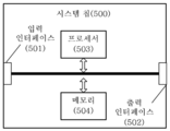
제 5 양태는 입력 인터페이스, 출력 인터페이스, 프로세서 및 메모리를 포함하고, 프로세서는 메모리에 기억된 명령어를 실행하고, 명령어가 실행되면 프로세서는 제 1 양태 또는 제 1 양태의 임의의 가능한 실현 방식에서 방법을 실현할 수 있는 시스템 칩을 제공한다.The fifth aspect includes an input interface, an output interface, a processor and memory, the processor executes instructions stored in memory, and when the instructions are executed, the processor executes the method in the first aspect or in any possible implementation manner of the first aspect. Provided is a system chip that can be realized.
제 6 양태는 명령어를 포함한 컴퓨터 프로그램 제품을 제공하고, 컴퓨터 프로그램 제품이 컴퓨터에서 실행되면 컴퓨터에 제 1 양태 또는 제 1 양태의 임의의 가능한 실현 방식에서 방법을 실행시킨다.The sixth aspect provides a computer program product including instructions, and when the computer program product is executed on a computer, executes the method on the computer in the first aspect or any possible realization manner of the first aspect.
도 1은 본 발명의 실시예에서 응용 장면의 모식도이다.
도 2는 본 발명의 실시예에서 신호 전송 방법의 흐름도이다.
도 3은 본 발명의 실시예에서 단말기 디바이스의 블록도이다.
도 4는 본 발명의 실시예에서 단말기 디바이스의 구성도이다.
도 5는 본 발명의 실시예에서 시스템 칩의 구성도이다.1 is a schematic diagram of an application scene in an embodiment of the present invention.
2 is a flowchart of a signal transmission method in an embodiment of the present invention.
3 is a block diagram of a terminal device in an embodiment of the present invention.
4 is a configuration diagram of a terminal device in an embodiment of the present invention.
5 is a block diagram of a system chip in an embodiment of the present invention.
이하에서는 도면을 참조하여, 본 발명의 실시예의 기술 방안에 대해 설명한다.Hereinafter, with reference to the drawings, a description will be given of a technical scheme of an embodiment of the present invention.
또한, 본 발명의 실시예의 기술 방안은 예를 들어, 글로벌 이동 통신(Global System of Mobile communication : GSM) 시스템, 코드 분할 다중 접속(Code Division Multiple Access : CDMA) 시스템, 광대역 코드 분할 다중 접속(Wideband Code Division Multiple Access : WCDMA) 시스템, 장기 진화(Long Term Evolution : LTE) 시스템, LTE 주파수 분할 복신(Frequency Division Duplex : FDD) 시스템, LTE 시분할 복신(Time Divi ion Duplex : TDD), 범용 이동 통신 시스템(Universal Mobile Telecommunication System : UMTS), 또는 미래의 5G 시스템 등의 다양한 통신 시스템에 응용될 수 있는 것으로 이해하여야 한다.In addition, the technical scheme of the embodiment of the present invention, for example, a global mobile communication (Global System of Mobile communication: GSM) system, a code division multiple access (CDMA) system, a wideband code division multiple access (Wideband Code) Division Multiple Access (WCDMA) system, Long Term Evolution (LTE) system, LTE Frequency Division Duplex (FDD) system, LTE Time Division Duplex (TDD), Universal Mobile Communication System (Universal) It should be understood that it can be applied to various communication systems such as Mobile Telecommunication System (UMTS) or future 5G systems.
본 발명은 단말기 디바이스와 관련하여 다양한 실시예를 기술한다. 단말기 디바이스는 사용자 장비(User Equipment), 액세스 단말기, 사용자 유닛, 사용자 스테이션, 이동 스테이션, 이동국, 원격 스테이션, 원격 단말기, 모바일 디바이스, 사용자 단말기, 단말기, 무선 통신 장치, 사용자 에이전트 또는 사용자 장치를 가르킬 수 있다. 액세스 단말기는 셀룰러 전화, 무선 전화, 세션 개시 프로토콜(Session Initiation Protocol : SIP) 전화, 무선 로컬 루프(Wireless Local Loop : WLL) 스테이션, 개인 디지털 처리(Personal Digital Assistant : PDA), 무선 통신 기능을 갖는 휴대용 장치, 컴퓨팅 장치 또는 무선 모뎀에 연결된 다른 처리 장치, 자동차 장치, 웨어러블 장치, 미래의 5G 네트워크의 단말기 디바이스, 또는 미래 진화형의 공중 육상 이동 네트워크(Public Land Mobile Network : PLMN)의 단말기 디바이스 등일 수 있다.The present invention describes various embodiments in connection with a terminal device. A terminal device is a user equipment, access terminal, user unit, user station, mobile station, mobile station, remote station, remote terminal, mobile device, user terminal, terminal, wireless communication device, user agent or user device. You can. Access terminals include cellular telephones, wireless telephones, Session Initiation Protocol (SIP) telephones, Wireless Local Loop (WLL) stations, Personal Digital Assistants (PDAs), and portables with wireless communication capabilities. It may be a device, a computing device or another processing device connected to a wireless modem, a vehicle device, a wearable device, a terminal device of the future 5G network, or a terminal device of the future evolution of the Public Land Mobile Network (PLMN).
본 발명은 네트워크 디바이스와 관련하여 다양한 실시예를 기술한다. 네트워크 디바이스는 단말기 디바이스와 통신하기 위한 디바이스일 수 있으며, 상기 네트워크 디바이스는 GSM 또는 CDMA의 기지국(Base Transceiver Station : BTS), WCDMA 시스템의 기지국(NodeB : NB), LTE 시스템의 진화형 기지국(Evolutional NodeB : eNB 또는 eNodeB), 또는 상기 네트워크 디바이스는 중계국, 액세스 포인트, 자동차 장치, 웨어러블 장치 및 미래의 5G 네트워크에서의 네트워크 측 디바이스 또는 미래 진화형의 PLMN 네트워크의 네트워크 측 디바이스 등일 수 있다.The present invention describes various embodiments in connection with a network device. The network device may be a device for communicating with a terminal device, and the network device may be a base station (BTS) of GSM or CDMA, a base station (NodeB: NB) of a WCDMA system, or an evolved base station of an LTE system (Evolutional NodeB: eNB or eNodeB), or the network device may be a relay station, an access point, a vehicle device, a wearable device, a network side device in a future 5G network, or a network side device in a future evolutionary PLMN network.
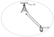
도 1은 본 발명의 실시예의 적용 장면의 모식도이다. 도 1의 통신 시스템은 단말기 디바이스(20)와 네트워크 디바이스(10)를 포함할 수 있다. 네트워크 디바이스(10)는 단말기 디바이스(20)에 통신 서비스를 제공하고 코어 네트워크에 액세스할 수 있도록 구성된다. 단말기 디바이스(20)는 네트워크 디바이스(10)가 송신하는 동기 신호, 방송 신호 등을 검색하여 네트워크에 액세스하고, 네트워크와의 통신을 진행한다. 도 1에 나타낸 화살표는 단말기 디바이스(20)와 네트워크 디바이스(10) 사이의 셀룰러 링크를 통해 진행하는 상향/하향 전송을 나타낼 수 있다.1 is a schematic view of an application scene of an embodiment of the present invention. The communication system of FIG. 1 may include a terminal device 20 and a
본 발명의 실시예에서 네트워크는 공중 육상 이동 네트워크(PLMN) 또는 디바이스투디바이스(Device to Device : D2D) 네트워크 또는 기계 대 기계/사람(Machine to Machine/Man : M2M) 네트워크 또는 다른 네트워크를 가르킬 수 있고, 도 1은 예시적인 단순화된 모식도일 뿐이며, 네트워크는 또한 도 1에 도시되지 않은 다른 단말기 디바이스를 포함할 수 있다. In an embodiment of the present invention, the network may refer to a public land mobile network (PLMN) or a device to device (D2D) network, or a machine to machine / man (M2M) network or other network. 1 is only an exemplary simplified schematic diagram, and the network may also include other terminal devices not shown in FIG. 1.
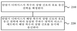
도 2는 본 발명의 실시예에 따른 신호 전송 방법의 개략적인 흐름도이다. 도 2에 표시된 방법은 예를 들어, 도 1에 도시된 단말기 디바이스(20)일 수 있는 단말기 디바이스에 의해 실행될 수 있다. 도 2에 나타낸 바와 같이, 해당 신호 전송 방법은 단계 210 및 단계 220를 포함한다.2 is a schematic flowchart of a signal transmission method according to an embodiment of the present invention. The method shown in FIG. 2 may be executed by a terminal device, which may be, for example, the terminal device 20 shown in FIG. 1. As shown in FIG. 2, the corresponding signal transmission method includes
단계 210에서, 단말기 디바이스가 복수의 상향 신호의 유효 송신 전력을 확정한다.In
단계 220에서, 단말기 디바이스가 해당 복수의 상향 신호의 유효 송신 전력에 따라 동일한 주파수 영역의 리소스 세트에서 해당 복수의 상향 신호를 동시에 송신한다.In
구체적으로는, 단말기 디바이스는 복수의 상향 신호의 유효 송신 전력을 각각 확정하고, 이를 통해 송신 전력을 적절히 할당하여, 단말기 디바이스가 복수의 상향 신호의 유효 송신 전력에 따라 동일한 주파수 영역의 리소스 세트에서 복수의 상향 신호를 동시에 전송할 수 있다.Specifically, the terminal devices respectively determine the effective transmission powers of the plurality of uplink signals, and appropriately allocate transmission powers through the terminal devices, so that the terminal devices perform a plurality of resource sets in the same frequency domain according to the effective transmission powers of the plurality of uplink signals. The uplink signal of can be transmitted at the same time.
단말기 디바이스는 상향 신호를 하나만 송신하는 경우, 예를 들어, 상향 신호에 대한 개 루프 전력 제어 또는 폐 루프 전력 제어를 관련 파라미터에 의해 실시하고, 해당 상향 정보를 위해 하나의 송신 전력을 확정할 수 있고, 해당 송신 전력을 본 발명에서는 예상 송신 전력이라고 지칭할 수 있다. 즉, 기존의 수단으로 일 상향 신호의 예상 송신 전력을 확정할 수 있다. 그러나, 본 발명의 실시예에서는 복수의 상향 신호를 동시에 송신하기 때문에, 단말기 디바이스가 동일한 주파수 영역의 리소스 세트에서 복수의 상향 신호를 동시에 전송되도록 스케줄링된 경우, 여전히 각 상향 신호의 예상 송신 전력으로 동시에 이러한 상향 신호를 송신하면, 단말기 디바이스의 송신 전력이 제한될 수 있기 때문에, 본 발명의 실시예는 단말기 디바이스가 복수의 상향 신호의 유효 송신 전력에 따라 동일한 주파수 영역의 리소스 세트에서 복수의 상향 신호를 동시에 전송하도록, 상향 신호마다 각 상향 신호의 유효 송신 전력을 다음과 같이 재확정한다.When only one uplink signal is transmitted by the terminal device, for example, open-loop power control or closed-loop power control for the uplink signal may be performed by a related parameter, and one transmission power may be determined for the uplink information. , The corresponding transmission power may be referred to as an expected transmission power in the present invention. That is, it is possible to determine the expected transmission power of one uplink signal using conventional means. However, in the embodiment of the present invention, since a plurality of uplink signals are simultaneously transmitted, when a terminal device is scheduled to transmit a plurality of uplink signals simultaneously in a resource set of the same frequency domain, it is still at the same time as the expected transmission power of each uplink signal. Since transmitting power of the terminal device may be limited when transmitting the uplink signal, the embodiment of the present invention allows the terminal device to transmit a plurality of uplink signals in a resource set of the same frequency domain according to the effective transmission power of the plurality of uplink signals. To transmit simultaneously, the effective transmission power of each uplink signal is re-determined as follows for each uplink signal.
선택적으로, 해당 복수의 상향 신호는 상향 데이터 또는 상향 기준 신호를 포함한다.Optionally, the plurality of uplink signals include uplink data or an uplink reference signal.
예를 들어, 해당 복수의 상향 신호는 복수의 물리 상향 공유 채널(Physical Uplink Shared Channel, PUSCH)일 수 있거나, 또는 하나의 PUSCH에서 부동한 전송 계층일 수 있거나, 또는 하나의 PUSCH에서 부동한 코드 워드일 수 있다. 또는 복수의 상향 신호는 복수의 사운딩 기준 신호(Sounding Reference Signal, SRS)일 수 있다.For example, the plurality of uplink signals may be a plurality of physical uplink shared channels (Physical Uplink Shared Channel, PUSCH), or may be a different transport layer in one PUSCH, or a code word different in one PUSCH Can be Alternatively, the plurality of uplink signals may be a plurality of sounding reference signals (SRS).
선택적으로 해당 복수의 상향 신호는 동일한 하향 제어 정보(Download Control Information, DCI)가 스케줄링된 상향 신호 또는 부동한 DCI가 각각 스케줄링된 상향 신호일 수 있다.Optionally, the plurality of uplink signals may be uplink signals with the same downlink control information (Download Control Information, DCI) scheduled or uplink signals with different DCIs scheduled respectively.
예를 들어, 해당 상향 신호는 동일한 DCI에 의해 스케줄링되는 복수의 PUSCH이거나, 또는 동일한 DCI에 의해 트리거되는 복수의 비 주기적 SRS이거나, 또는 복수의 DCI에 의해 각각 스케줄링되는 복수의 독립적인 PUSCH이거나, 또는 복수의 DCI에 의해 각각 트리거되는 복수의 독립적인 비 주기적 SRS이다.For example, the uplink signal is a plurality of PUSCHs scheduled by the same DCI, or a plurality of aperiodic SRSs triggered by the same DCI, or a plurality of independent PUSCHs each scheduled by a plurality of DCIs, or It is a plurality of independent aperiodic SRSs, each triggered by a plurality of DCIs.
선택적으로 해당 동일한 주파수 영역의 리소스 세트는 동일한 캐리어, 동일한 좁은 대역폭, 동일한 서브 밴드 또는 동일한 물리 리소스 블록(Physical Resource Block, PRB) 세트를 포함한다.Optionally, the resource set in the same frequency domain includes the same carrier, the same narrow bandwidth, the same subband, or the same set of physical resource blocks (PRBs).
즉, 하나의 주파수 영역의 리소스 세트는 하나의 캐리어(Carrier), 하나의 좁은 대역폭(Bandwidth Part), 하나의 서브 밴드(Sub-band) 또는 하나의 PRB 세트일 수 있다.That is, a resource set in one frequency domain may be one carrier, one narrow bandwidth part, one sub-band, or one PRB set.
본 발명의 실시예에서는 복수의 상향 신호의 유효 송신 전력을 확정하는 4 가지 방법이 제공되며, 다음에 구체적으로 설명한다.In the embodiment of the present invention, four methods for determining the effective transmission power of a plurality of uplink signals are provided, which will be described in detail later.
방식 1Method 1
선택적으로, 단계 210에서, 단말기 디바이스가 복수의 상향 신호의 유효 송신 전력을 확정하는 단계는 단말기 디바이스가 상기 복수의 상향 신호의 신호 수량에 따라 해당 복수의 상향 신호의 유효 송신 전력을 확정하는 단계를 포함한다.Optionally, in
또한, 단말기 디바이스는 구체적으로는 다음의 두 가지 방식을 통하여, 복수의 상향 신호의 신호 수량에 따라 복수의 상향 신호의 유효 송신 전력을 확정할 수 있다. 한가지 방식은 상기 복수의 상향 신호의 신호 수량에서 상기 복수의 상향 신호 중 각 상향 신호의 최대 허용 송신 전력을 직접 확정하고, 해당 최대 허용 송신 전력에 따라 각 상향 신호의 유효 송신 전력을 확정하고, 다른 한가지 방식은 복수의 상향 신호의 신호 수량에 따라 비율을 취득하고, 해당 비율에 따라 각 상향 신호의 예상 송신 전력을 저감시킴으로써, 각 상향 신호의 유효 송신 전력을 취득하고, 다음, 구체적으로 설명한다.In addition, the terminal device may specifically determine the effective transmission power of the plurality of uplink signals according to the signal quantity of the plurality of uplink signals through the following two methods. In one method, the maximum allowable transmission power of each uplink signal among the plurality of uplink signals is directly determined from the signal quantity of the plurality of uplink signals, and the effective transmission power of each uplink signal is determined according to the maximum allowable transmission power. One method acquires a ratio according to the signal quantity of a plurality of uplink signals, and reduces the expected transmission power of each uplink signal according to the ratio, thereby acquiring effective transmission power of each uplink signal, and will be described in detail below.
선택적으로, 단말기 디바이스가 상기 복수의 상향 신호의 신호 수량에 따라 해당 복수의 상향 신호의 유효 송신 전력을 확정하는 단계는, 단말기 디바이스가 상기 복수의 상향 신호의 신호 수량에 따라 해당 복수의 상향 신호 중 각 상향 신호의 최대 허용 송신 전력을 확정하는 단계, 및 단말기 디바이스가 각 상향 신호의 최대 허용 송신 전력에 따라 각 상향 신호의 유효 송신 전력을 확정하는 단계를 포함한다.Optionally, the step of determining the effective transmission power of the plurality of uplink signals according to the signal quantity of the plurality of uplink signals is performed by the terminal device among the plurality of uplink signals according to the signal quantity of the plurality of uplink signals. And determining a maximum allowable transmit power of each uplink signal, and a terminal device determining an effective transmit power of each uplink signal according to the maximum allowable transmit power of each uplink signal.
예를 들어, 송신될 복수의 상향 신호의 신호 수량을 N으로, 단말기 디바이스에 의해 지원되는 최대 송신 전력을 Pmax으로 가정하면, 단말기 디바이스는 단말기 디바이스에 의해 지원되는 최대 송신 전력 Pmax 및 신호 수량 N에 따라, 각 상향 신호의 최대 허용 송신 전력은 Pmax/N인 것으로 확정할 수 있다. 이후, 단말기 디바이스는 기존의 상향 전력 제어 과정을 사용하여, 각 상향 신호의 최대 허용 송신 전력에 따라 각 상향 신호의 유효 송신 전력을 확정할 수 있다.For example, assuming that the signal quantity of a plurality of uplink signals to be transmitted is N and the maximum transmission power supported by the terminal device is P max , the terminal device is the maximum transmission power P max and signal quantity supported by the terminal device. According to N, the maximum allowable transmission power of each uplink signal can be determined to be P max / N. Thereafter, the terminal device may determine the effective transmission power of each uplink signal according to the maximum allowable transmission power of each uplink signal using an existing uplink power control process.
상향 신호마다 각각의 최대 허용 송신 전력을 가지고, 최종적으로 해당 상향 신호를 송신하기 위한 유효 송신 전력은 해당 상향 신호에 대응하는 최대 허용 송신 전력을 초과하지 않는다. 단말기 디바이스가 지원하는 최대 송신 전력은 각 상향 신호의 각각의 최대 허용 송신 전력과는 부동하게, 단말기 디바이스가 1 회 송신할 때 제공 가능한 전체 송신 전력이다.Each uplink signal has a maximum allowable transmit power, and finally, the effective transmit power for transmitting the uplink signal does not exceed the maximum allowable transmit power corresponding to the uplink signal. The maximum transmit power supported by the terminal device is the total transmit power that can be provided when the terminal device transmits once, different from the maximum allowable transmit power of each uplink signal.
선택적으로, 단말기 디바이스가 상기 복수의 상향 신호의 신호 수량에 따라 해당 복수의 상향 신호의 유효 송신 전력을 확정하는 단계는, 단말기 디바이스가 해당 신호 수량에 대응하는 비율에 따라 해당 복수의 상향 신호 중 각 상향 신호의 예상 송신 전력을 저감시키고, 저감시킨 후 각 상향 신호의 예상 송신 전력을 각 상향 신호의 유효 송신 전력으로 확정하는 단계를 포함한다.Optionally, the step of determining the effective transmission power of the plurality of uplink signals according to the signal quantity of the plurality of uplink signals by the terminal device is performed by each of the plurality of uplink signals according to the ratio corresponding to the signal quantity of the terminal device. And reducing the expected transmission power of the uplink signal, and determining the expected transmission power of each uplink signal as the effective transmission power of each uplink signal after the reduction.
예를 들어, 해당 복수의 상향 신호 중 각 상향 신호의 예상 송신 전력을 Pi(0 < i ≤ N)로, N을 해당 복수의 상향 신호의 신호 수량으로, 각 N 값은 하나의 비율에 대응하고, 수량 N에 대응하는 비율을 1/N이라고 가정하면, 상향 신호의 각각의 유효 송신 전력은 Pi/N으로 저감될 수 있다. 수량 N에 대응하는 비율을 1/2N이면, 각 상향 신호의 유효 송신 전력을 Pi/2N로 저감시킬 수 있다. 해당 예상 송신 전력을 저감하는 과정은 예를 들어, 단말기 디바이스의 소비 전력의 저감이 필요한 경우에 사용될 수 있거나, 또는 복수의 상향 신호의 예상 송신 전력의 합이 단말기 디바이스가 지원하는 최대 송신 전력을 초과하는 경우에만 사용될 수 있다.For example, among the plurality of uplink signals, the estimated transmission power of each uplink signal is Pi (0 <i ≤ N), N is the signal number of the plurality of uplink signals, and each N value corresponds to one ratio. , Assuming that the ratio corresponding to the quantity N is 1 / N, the effective transmission power of each of the uplink signals can be reduced to Pi / N. If the ratio corresponding to the quantity N is 1 / 2N, the effective transmission power of each uplink signal can be reduced to Pi / 2N. The process of reducing the expected transmission power may be used when, for example, it is necessary to reduce power consumption of the terminal device, or the sum of the expected transmission power of a plurality of uplink signals exceeds the maximum transmission power supported by the terminal device Can only be used if
방식 2Method 2
선택적으로, 단계 210에서, 단말기 디바이스가 복수의 상향 신호의 유효 송신 전력을 확정하는 단계는, 단말기 디바이스가 상기 복수의 상향 신호의 우선 순위 정보에 따라 해당 복수의 상향 신호의 유효 송신 전력을 확정하는 단계를 포함한다.Optionally, in
해당 복수의 상향 신호의 우선 순위 정보는 예를 들어, 네트워크가 해당 복수의 상향 신호를 위해 미리 구성된다.Priority information of the plurality of uplink signals, for example, the network is pre-configured for the plurality of uplink signals.
여기서, 선택적으로, 단말기 디바이스가 상기 복수의 상향 신호의 우선 순위 정보에 따라 해당 복수의 송신 전력을 확정하는 단계 전에, 해당 방법은 또한 단말기 디바이스가 해당 복수의 상향 신호의 신호 유형, 해당 복수의 상향 신호를 스케줄링하는 제어 시그널링, 해당 복수의 상향 신호에 포함된 정보의 유형 및 해당 복수의 상향 신호가 스케줄링되는 순서 중 적어도 하나에 따라 해당 복수의 상향 신호의 우선 순위 정보를 확정하는 단계를 포함한다.Here, optionally, prior to the step of the terminal device determining the plurality of transmission powers according to the priority information of the plurality of uplink signals, the method also includes the terminal device having the signal types of the plurality of uplink signals and the plurality of uplinks. And determining priority information of the plurality of uplink signals according to at least one of a control signaling for scheduling signals, a type of information included in the plurality of uplink signals, and an order in which the plurality of uplink signals are scheduled.
예를 들어, 단말기 디바이스가 해당 복수의 상향 신호를 스케줄링하는 제어 시그널링에 따라 복수의 상향 신호의 우선 순위 정보를 확정하는 경우, 단말기 디바이스는 복수의 상향 신호를 스케줄링하기 위한 복수의 DCI를 수신하여 복수의 상향 신호의 우선 순위 정보를 취득하고, 여기서 해당 복수의 DCI는 복수의 상향 신호의 우선 순위 정보를 운반하거나, 또는 단말기 디바이스는 해당 복수의 상향 신호를 스케줄링하기 위해 복수의 DCI를 수신하고, 해당 복수의 DCI에 포함된 변조 코딩 방식(Modulation Coding Mode, MCS)의 정보에 따라 해당 복수의 상향 신호의 우선 순위 정보를 확정할 수 있다. 예를 들어, 네트워크 디바이스는 하나 또는 복수의 DCI를 통하여 복수의 상향 신호에 독립적으로 각 상향 신호의 MCS 레벨을 지시할 수 있고, 여기에서 MCS 레벨이 높은 상향 신호일수록 우선 순위가 더 높다 .For example, when the terminal device determines priority information of a plurality of uplink signals according to control signaling for scheduling the plurality of uplink signals, the terminal device receives a plurality of DCIs for scheduling the plurality of uplink signals and receives a plurality of Priority information of the uplink signal is obtained, where the plurality of DCIs carry priority information of the plurality of uplink signals, or the terminal device receives a plurality of DCIs to schedule the plurality of uplink signals, and the corresponding Priority information of a plurality of uplink signals may be determined according to information of a modulation coding mode (MCS) included in a plurality of DCIs. For example, the network device may independently indicate the MCS level of each uplink signal to a plurality of uplink signals through one or a plurality of DCIs. Here, the higher the MCS level, the higher the priority.
또한 예를 들어, 단말기 디바이스가 복수의 상향 신호에 포함된 정보의 유형에 따라 복수의 상향 신호의 우선 순위 정보를 확정하는 경우, 물리 상향 제어 채널(Physical Uplink Control Channel, PUCCH)의 우선 순위는 PUSCH보다 높고, PUCCH의 우선 순위는 SRS보다 높고, PUCCH의 우선 순위는 위상 추적 기준 신호(Phase Tracking Reference Signal, PTRS)보다 높고, PTRS의 우선 순위는 SRS보다 높고, PUSCH의 우선 순위는 SRS보다 높고, 확인(Acknowledgement, ACK)/부정 확인(Negative Acknowledgement, NACK) 정보가 포함된 PUCCH의 우선 순위는 채널 상태 정보(Channel State Information, CSI)가 포함된 PUCCH보다 높은 규칙에 근거할 수 있다.Also, for example, when the terminal device determines priority information of a plurality of uplink signals according to the type of information included in the plurality of uplink signals, the priority of the physical uplink control channel (PUCCH) is PUSCH Higher, PUCCH has higher priority than SRS, PUCCH has higher priority than Phase Tracking Reference Signal (PTRS), PTRS has higher priority than SRS, and PUSCH has higher priority than SRS, The priority of a PUCCH including acknowledgment (ACK) / negative acknowledgment (NACK) information may be based on a higher rule than a PUCCH including channel state information (CSI).
UCI가 포함되지 않은 PUSCH보다 상향 제어 정보(Uplink Control Information, UCI)가 포함된 PUSCH의 우선 순위가 더 높다. 또는 초고신뢰 초저지연(Ultra Reliable Low Latency Communication, URLLC) 데이터가 포함된 PUSCH의 우선 순위는 확장 모바일 광대역(Enhanced Mobile Broadband, eMBB) 데이터가 포함된 PUSCH보다 높다.PUSCHs containing uplink control information (UCI) have higher priority than PUSCHs not including UCI. Alternatively, PUSCHs with Ultra Reliable Low Latency Communication (URLLC) data have a higher priority than PUSCHs with Enhanced Mobile Broadband (eMBB) data.
또한 예를 들어, 단말기 디바이스가 상기 복수의 상향 신호가 스케줄링된 순서에 따라 해당 복수의 상향 신호의 우선 순위 정보를 확정할 때, 복수의 상향 신호가 복수의 DCI에 의해 각각 스케줄링되는 경우, 단말기 디바이스가 먼저 수신한 DCI에 의해 스케줄링된 상향 신호의 우선 순위는 다음으로 수신한 DCI에 의해 스케줄링된 상향 신호보다 높다. 또는, 단말기 디바이스가 다음으로 수신한 DCI에 의해 스케줄링된 상향 신호의 우선 순위는 먼저 수신한 DCI에 의해 스케줄링된 상향 신호보다 높다.Also, for example, when the terminal device determines priority information of the plurality of uplink signals according to the order in which the plurality of uplink signals are scheduled, when the plurality of uplink signals are respectively scheduled by the plurality of DCIs, the terminal device The priority of the uplink signal scheduled by DCI received first is higher than the uplink signal scheduled by DCI received next. Alternatively, the priority of the uplink signal scheduled by the DCI received by the terminal device is higher than the uplink signal scheduled by the DCI received first.
또한, 단말기 디바이스가 복수의 상향 신호의 우선 순위 정보를 획득한 후, 다음 방식으로 해당 복수의 상향 신호의 우선 순위 정보에 따라 해당 복수의 상향 신호의 유효 송신 전력을 확정할 수 있다.In addition, after the terminal device acquires the priority information of the plurality of uplink signals, it is possible to determine the effective transmission power of the plurality of uplink signals according to the priority information of the plurality of uplink signals in the following manner.
선택적으로, 단말기 디바이스가 상기 복수의 상향 신호의 우선 순위 정보에 따라 해당 복수의 상향 신호의 유효 송신 전력을 확정하는 단계는, 단말기 디바이스가 상기 복수의 상향 신호를 위해 각각의 최소 송신 전력을 할당하는 단계, 및, 단말기 디바이스가 지원하는 최대 송신 전력에서 해당 복수의 상향 신호의 최소 송신 전력을 제외한 잉여 송신 전력을 해당 복수의 상향 신호의 우선 순위 정보에 따라 해당 복수의 상향 신호의 적어도 일부 상향 신호에 할당하는 단계를 포함한다.Optionally, the step of the terminal device determining the effective transmission powers of the plurality of uplink signals according to the priority information of the plurality of uplink signals, wherein the terminal device allocates each minimum transmission power for the plurality of uplink signals. Step, and, at least a portion of the uplink signal of the plurality of uplink signals in accordance with the priority information of the plurality of uplink signals, except for the minimum transmit power of the plurality of uplink signals from the maximum transmission power supported by the terminal device And assigning.
구체적으로, 단말기 디바이스는 복수의 상향 대한 최소 송신 전력(또는 최소 허용 송신 전력이라 지칭함)을 일시적으로 할당할 수 있다. 다음으로, 단말기 디바이스는 지원하는 최대 송신 전력에서 복수의 상향 신호의 최소 허용 송신 전력을 감산하고, 잉여 송신 전력을 할당한다. 상기 단말기 디바이스는 상기 복수의 상향 신호의 우선 순위 정보에 따라 상기 잉여 송신 전력을 우선 순위가 높은 것으로부터 낮은 순서로 할당하고, 상기 복수의 상향 신호 중 우선 순위가 높은 상향 신호의 적어도 일부를 송신 전력에 다시 할당하고, 이를 통해 상기 상향 신호의 적어도 일부가 상기 최소 허용 송신 전력에 할당될 수 있는 기초상에서, 예를 들어, 각각의 상기 최대 허용 송신 전력에 도달하거나, 또는 각각의 최대 허용 송신 전력의 일정 비율에 도달되도록하여, 전력 증가를 다시 진행한다.Specifically, the terminal device may temporarily allocate a plurality of uplink minimum transmission powers (or referred to as minimum allowable transmission powers). Next, the terminal device subtracts the minimum allowable transmission power of the plurality of uplink signals from the maximum transmission power supported and allocates the excess transmission power. The terminal device allocates the surplus transmission power according to priority information of the plurality of uplink signals in order from high priority to low priority, and transmits at least a portion of the uplink signal having high priority among the plurality of uplink signals. On the basis that at least a portion of the uplink signal can be allocated to the minimum allowable transmit power, for example, each of the maximum allowable transmit power is reached, or By allowing a certain percentage to be reached, the power increases again.
예를 들어, 송신될 복수의 상향 신호의 신호 수량을 N으로, 각 상향 신호의 최소 송신 전력을 Pmin으로, 단말기 디바이스가 지원하는 최대 송신 전력을 Pmax로, N 개의 상향 신호 중 i 번째 상향 신호의 최대 송신 전력을 Pi-max로 가정하면, 잉여 송신 전력 Pr = Pmax-N × Pmin이다. 단말기 디바이스는 먼저 상향 신호마다 각각의 최소 송신 전력 Pmin을 할당한 다음, 단말기 디바이스는 잉여 송신 전력 Pr을 상향 신호의 우선 순위에 따라 순차적으로 할당하고, N을 3으로, 즉 복수의 상향 신호의 신호 수량이 3이고, 각각 신호 1, 신호 2, 신호 3이며, 잉여 전력의 할당을 진행하지 않은 경우 신호 1, 신호 2, 신호 3 모두에 Pmin을 할당한 다음, 단말기 디바이스는 이러한 세 개의 신호의 우선 순위 정보를 상기 방식으로 획득할 수 있고, 우선 순위가 높은 것으로부터 낮은 순서로 신호 1> 신호 2> 신호 3이라고 가정하면, 단말기 디바이스는 잉여 송신 전력 Pr을 우선적으로 우선 순위가 가장 높은 신호 1에 할당하고, 예를 들어, 송신 전력이 Pmin으로부터 최대 송신 전력 P1-max에 도달하도록하고, 이때 신호 1의 유효 송신 전력은 최대 허용 송신 전력 Pmax과 동일하고, 이때 잉여 송신 전력 Pr이 남아있으면, 계속하여 신호 2에 송신 전력을 할당하고, 신호 2의 송신 전력이 Pmin으로부터 최대 송신 전력 P2-max에 도달한 후에도 여전히 남아있다면, 계속하여 신호 3에 송신 전력을 할당한다. 잉여 송신 전력이 할당 과정에서 전부 할당되어, 계속 할당하는데 불충분하면 동작을 정지한다. 물론 마지막으로 송신 전력이 할당된 신호의 유효 송신 전력은 그 최대 송신 전력에 도달되지 않을 수 있다.For example, the number of signals of a plurality of uplink signals to be transmitted is N, the minimum transmission power of each uplink signal is P min , the maximum transmission power supported by the terminal device is P max , and the i th upward of the N uplink signals Assuming that the maximum transmission power of the signal is P i-max , the surplus transmission power P r = P max -N × P min . The terminal device first allocates each minimum transmission power P min for each uplink signal, and then the terminal device sequentially allocates excess transmission power P r according to the priority of the uplink signal, and N is 3, that is, a plurality of uplink signals. If the signal quantity of is 3, respectively, signal 1, signal 2, and signal 3 are allocated and surplus power is not allocated, P min is allocated to all of signal 1, signal 2, and signal 3, and then the terminal device Assuming that the priority information of the signal can be obtained in the above manner, and assuming that the signal 1> signal 2> signal 3 is ordered from the highest priority to the lowest priority, the terminal device preferentially gives the surplus transmission power Pr the highest priority. assigned to the first signal, and, for example, and that the transmission power reaches the maximum transmission power P max from 1-P min, wherein the effective transmit power of signal 1 is the maximum allowable transmission Equal to the power P max, and wherein, if the surplus transmission power P r remains, even after continued by allocating a transmit power to signal 2, the transmission power of the signal 2 reaches the maximum transmit power P 2-max from P min remains If yes, continue to allocate transmit power to signal 3. If all of the excess transmit power is allocated during the allocation process and it is insufficient to continue allocation, the operation is stopped. Of course, the effective transmission power of the signal to which transmission power is finally allocated may not reach its maximum transmission power.
방식 3Method 3
선택적으로, 단말기 디바이스가 복수의 상향 신호의 유효 송신 전력을 확정하는 단계는 해당 복수의 상향 신호의 예상 송신 전력의 합이 단말기 디바이스가 지원하는 최대 송신 전력보다 큰 경우, 단말기 디바이스가 해당 최대 송신 전력과 해당 복수의 상향 신호의 예상 송신 전력의 합의 비율에 따라, 해당 복수의 상향 신호 중 각 상향 신호의 예상 송신 전력을 저감시키고, 저감시킨 후 각 상향 신호의 예상 송신 전력을 각 상향 신호의 유효 송신 전력으로 확정하는 단계를 포함한다.Optionally, the step of determining the effective transmission power of the plurality of uplink signals by the terminal device is when the sum of the expected transmission powers of the plurality of uplink signals is greater than the maximum transmission power supported by the terminal device, the terminal device determines the maximum transmission power. And the estimated transmission power of each uplink signal among the plurality of uplink signals according to the ratio of the sum of the expected transmission powers of the plurality of uplink signals, and after reducing, the estimated transmission power of each uplink signal is effective transmission of each uplink signal. And determining with electric power.
구체적으로, 단말기 디바이스는 복수의 상향 신호의 예상 송신 전력의 합이 단말기 디바이스가 지원하는 최대 송신 전력을 초과하는 경우, 복수의 상향 신호 중 각 상향 신호의 예상 송신 전력을 일정한 비율로 저감시키고, 저감시킨 후 예상 송신 전력을 상향 신호의 유효 송신 전력으로 할 수 있다. 선택적으로, 해당 비율은 단말기 디바이스가 지원하는 최대 송신 전력과 복수의 상향 신호의 예상 송신 전력의 합에 따라 확정될 수 있다.Specifically, when the sum of the expected transmission powers of the plurality of uplink signals exceeds the maximum transmission power supported by the terminal device, the terminal device reduces and reduces the expected transmission power of each uplink signal among the plurality of uplink signals at a constant rate. After that, the expected transmission power can be the effective transmission power of the uplink signal. Optionally, the ratio may be determined according to the sum of the maximum transmission power supported by the terminal device and the expected transmission power of the plurality of uplink signals.
예를 들어, 단말기 디바이스가 지원하는 최대 송신 전력을 Pmax으로, 송신될 복수의 상향 신호의 신호 수량을 N으로, 기존의 상향 전력 제어 과정에서 N 개의 상향 신호 중 i 번째 상향 신호의 예상 송신 전력 Pi로 가정하면, 복수의 상향 신호의 예상 송신 전력의 합이 ![]()
![]()
방식 4Method 4
선택적으로, 단말기 디바이스가 복수의 상향 신호의 유효 송신 전력을 확정하는 단계는 단말기 디바이스가 네트워크에 의해 송신된 지시 정보를 수신하고, 해당 지시 정보는 상기 복수의 상향 신호에 대응하는 전력 제어 파라미터를 나타내는 단계, 및 단말기 디바이스가 상기 복수의 상향 신호에 대응하는 전력 제어 파라미터에 따라 해당 복수의 상향 신호의 유효 송신 전력을 확정하는 단계를 포함한다.Optionally, the step of determining the effective transmission power of the plurality of uplink signals by the terminal device is that the terminal device receives the indication information transmitted by the network, and the indication information indicates power control parameters corresponding to the plurality of uplink signals. And determining, by the terminal device, effective transmission power of the plurality of uplink signals according to a power control parameter corresponding to the plurality of uplink signals.
해당 전력 제어 파라미터는 예를 들어, 개 루프 전력 제어 파라미터, 폐 루프 전력 제어 파라미터, 경로 손실과 관련된 파라미터 등을 포함할 수 있다. 단말기 디바이스는 이러한 미리 설정된 전력 제어 파라미터에 따라 각 상향 신호의 유효 송신 전력을 확정하고, 예를 들어, 일반적으로 상향 전력 제어 과정에 의하여 이러한 전력 제어에 따라 각 상향 신호의 유효 송신 전력을 확정한다. 선택적으로, 상기 지시 정보는 SRS 리소스 지시 정보(SRS Resource Indication, SRI)이고, 상기 네트워크 디바이스는 상기 SRI를 통해 상기 단말기 디바이스에 전력 제어 파라미터를 지시하므로, 상기 단말기 디바이스는 상기 전력 제어 파라미터에 따라 상기 복수의 상향 신호의 유효 송신 전력을 확정할 수 있다.The power control parameter may include, for example, open loop power control parameters, closed loop power control parameters, path loss related parameters, and the like. The terminal device determines the effective transmission power of each uplink signal according to the preset power control parameter, and, for example, generally determines the effective transmission power of each uplink signal according to the power control by an uplink power control process. Optionally, the indication information is SRS Resource Indication (SRI), and since the network device indicates a power control parameter to the terminal device through the SRI, the terminal device is configured according to the power control parameter. The effective transmission power of a plurality of uplink signals can be determined.
해당 복수의 상향 신호의 유효 송신 전력을 확정한 후, 단말기 디바이스는 해당 복수의 상향 신호의 유효 송신 전력에 따라 동일한 주파수 영역의 리소스 세트에서 해당 복수의 상향 신호를 동시에 전송할 수 있다.After determining the effective transmission power of the plurality of uplink signals, the terminal device may simultaneously transmit the plurality of uplink signals in the resource set of the same frequency domain according to the effective transmission power of the plurality of uplink signals.
선택적으로, 단계 220에서, 단말기 디바이스가 상기 복수의 상향 신호의 유효 송신 전력에 따라 동일한 주파수 영역의 리소스 세트에서 해당 복수의 상향 신호를 동시에 송신하는 단계는, 단말기 디바이스가 상기 복수의 상향 신호의 유효 송신 전력에 따라 해당 동일한 주파수 영역의 리소스 세트의 부동한 주파수 영역의 리소스에서, 해당 복수의 상향 신호를 동시에 송신하는 단계를 포함한다.Optionally, in
선택적으로, 단계 220에서, 단말기 디바이스가 상기 복수의 상향 신호의 유효 송신 전력에 따라 동일한 주파수 영역의 리소스 세트에서 해당 복수의 상향 신호를 동시에 송신하는 단계는, 단말기 디바이스가 상기 복수의 상향 신호의 유효 송신 전력에 따라 해당 동일한 주파수 영역의 리소스 세트에서 부동한 안테나 어레이 블록(antenna panel)을 통해 해당 복수의 상향 신호를 동시에 송신하는 단계를 포함한다.Optionally, in
선택적으로, 단계 220에서, 단말기 디바이스가 상기 복수의 상향 신호의 유효 송신 전력에 따라 동일한 주파수 영역의 리소스 세트에서 해당 복수의 상향 신호를 동시에 송신하는 단계는, 단말기 디바이스가 상기 복수의 상향 신호의 유효 송신 전력에 따라 해당 동일한 주파수 영역의 리소스 세트에서 부동한 빔을 통해 해당 복수의 상향 신호를 동시에 송신하는 단계를 포함한다.Optionally, in
또한, 동시에 전송되는 해당 복수의 상향 신호 중 임의의 2 개의 상향 신호에 사용되는 2 개의 송신 빔은 동일한 안테나 어레이 블록에 의한 빔일 수 있고, 부동한 안테나 어레이 블록에 의해 발생된 빔일 수 있지만, 여기서 한정하지 않는다.In addition, the two transmission beams used for any two uplink signals of the corresponding plurality of uplink signals transmitted simultaneously may be beams by the same antenna array block or beams generated by different antenna array blocks, but are limited here. I never do that.
따라서, 본 실시예에 있어서, 단말기 디바이스는 일정한 전력 할당 방식에 따라 동일한 주파수 영역의 리소스 세트에서 동시에 전송될 복수의 상향 신호를 위해, 각각의 유효 송신 전력을 확정하고, 복수의 상향 신호의 유효 송신 전력에 따라 동일한 주파수 영역의 리소스 세트에서 해당 복수의 상향 신호를 동시에 전송한다. 이와 같이, 단말기 디바이스의 송신 전력이 제한되는 경우에도, 단말기 디바이스는 본 발명의 실시예에서 설명된 전력 할당 방식을 사용하여 전송될 복수의 상향 신호의 각각의 유효 송신 전력을 여전히 다시 확정함으로써, 동일한 주파수 영역 세트에서 복수의 상향 신호를 동시에 송신한다.Accordingly, in the present embodiment, the terminal device determines respective effective transmission powers for multiple uplink signals to be simultaneously transmitted in a resource set of the same frequency domain according to a constant power allocation method, and effective transmission of the plurality of uplink signals The plurality of uplink signals are simultaneously transmitted from a resource set in the same frequency domain according to power. In this way, even when the transmission power of the terminal device is limited, the terminal device still determines the effective transmission power of each of the plurality of uplink signals to be transmitted again by using the power allocation method described in the embodiment of the present invention, so that the same A plurality of uplink signals are simultaneously transmitted in a frequency domain set.
본 발명의 다양한 실시예에서, 상기 각 과정의 순서의 크기는 실행 순서의 선후를 의미하는 것이 아니고, 각 과정의 실행 순서는 기능 및 내부 로직에 의해 확정되어야하고, 본 발명의 실시예의 과정에 대해 제한하는 것이 아니라는 것을 이해하기 바란다.In various embodiments of the present invention, the size of the sequence of each process does not mean the precedence of the execution sequence, and the execution sequence of each process should be determined by functions and internal logic, and for the process of the embodiment of the present invention Please understand that it is not limiting.
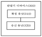
도 3은 본 발명의 실시예에서 단말기 디바이스(300)의 블록도이다. 도 3과 같이, 해당 단말기 디바이스(300)는 확정 유닛(310) 및 송신 유닛(320)을 포함한다.3 is a block diagram of a terminal device 300 in an embodiment of the present invention. As illustrated in FIG. 3, the corresponding terminal device 300 includes a determination unit 310 and a transmission unit 320.
확정 유닛(310)은 복수의 상향 신호의 유효 송신 전력을 확정하도록 구성된다.The determining unit 310 is configured to determine the effective transmission power of the plurality of uplink signals.
송신 유닛(320)은 상기 확정 유닛(310)에 의해 확정된 상기 복수의 상향 신호의 유효 송신 전력에 따라 동일한 주파수 영역의 리소스 세트에서 상기 복수의 상향 신호를 동시에 송신하도록 구성된다.The transmission unit 320 is configured to simultaneously transmit the plurality of uplink signals in a resource set of the same frequency domain according to the effective transmission power of the plurality of uplink signals determined by the determination unit 310.
따라서, 단말기 디바이스는 일정한 전력 할당 방식에 따라 동일한 주파수 영역의 리소스 세트에서 동시에 전송될 복수의 상향 신호를 위해, 각각의 유효 송신 전력을 확정하고, 복수의 상향 신호의 유효 송신 전력에 따라 동일한 주파수 영역의 리소스 세트에서 해당 복수의 상향 신호를 동시에 전송한다. 이와 같이, 단말기 디바이스의 송신 전력이 제한되는 경우에도, 단말기 디바이스는 본 발명의 실시예에서 설명된 전력 할당 방식을 사용하여 전송될 복수의 상향 신호의 각각의 유효 송신 전력을 여전히 다시 확정함으로써, 동일한 주파수 영역 세트에서 복수의 상향 신호를 동시에 전송한다.Accordingly, the terminal device determines respective effective transmission powers for a plurality of uplink signals to be simultaneously transmitted in a resource set of the same frequency domain according to a constant power allocation scheme, and the same frequency domain according to the effective transmission powers of the plurality of uplink signals. A plurality of uplink signals are simultaneously transmitted in a resource set of. In this way, even when the transmission power of the terminal device is limited, the terminal device still determines the effective transmission power of each of the plurality of uplink signals to be transmitted again by using the power allocation method described in the embodiment of the present invention, so that the same A plurality of uplink signals are simultaneously transmitted in a frequency domain set.
선택적으로, 상기 복수의 상향 신호는 상향 데이터 또는 상향 기준 신호를 포함한다.Optionally, the plurality of uplink signals include uplink data or an uplink reference signal.
선택적으로, 상기 복수의 상향 신호는 동일한 하향 제어 정보 DCI에 의해 스케줄링된 상향 신호 또는 부동한 DCI에 의해 각각 스케줄링된 상향 신호이다.Optionally, the plurality of uplink signals are uplink signals scheduled by the same downlink control information DCI or uplink signals respectively scheduled by different DCIs.
선택적으로, 상기 동일한 주파수 영역의 리소스 세트는 동일한 캐리어, 동일한 좁은 대역폭, 동일한 서브 밴드 또는 동일한 물리 리소스 블록 PRB 세트를 포함한다.Optionally, the resource set in the same frequency domain includes the same carrier, the same narrow bandwidth, the same sub-band, or the same physical resource block PRB set.
선택적으로, 상기 확정 유닛(310)은 구체적으로, 상기 복수의 상향 신호의 신호 수량에 따라 상기 복수의 상향 신호의 유효 송신 전력을 확정하도록 구성된다.Optionally, the determining unit 310 is specifically configured to determine the effective transmission power of the plurality of uplink signals according to the signal quantity of the plurality of uplink signals.
선택적으로, 상기 확정 유닛(310)은 구체적으로, 상기 복수의 상향 신호의 신호 수량에 따라 상기 복수의 상향 신호 중 각 상향 신호의 최대 허용 송신 전력을 확정하고, 상기 각 상향 신호의 최대 허용 송신 전력에 따라 상기 각 상향 신호의 유효 송신 전력을 확정하도록 구성된다.Optionally, the determining unit 310 specifically determines the maximum allowable transmission power of each uplink signal among the plurality of uplink signals according to the signal quantity of the plurality of uplink signals, and the maximum allowable transmission power of each uplink signal. It is configured to determine the effective transmission power of each uplink signal according to.
선택적으로, 상기 확정 유닛(310)은 구체적으로, 상기 신호 수량에 대응하는 비율에 따라 상기 복수의 상향 신호 중 각 상향 신호의 예상 송신 전력을 저감시키고, 저감시킨 후 상기 각 상향 신호의 예상 송신 전력을 상기 각 상향 신호의 유효 송신 전력으로 확정하도록 구성된다.Optionally, the determining unit 310 specifically reduces the expected transmission power of each uplink signal among the plurality of uplink signals according to a ratio corresponding to the signal quantity, and reduces the expected transmission power of each uplink signal. It is configured to determine the effective transmission power of each of the uplink signal.
선택적으로, 상기 확정 유닛(310)은 구체적으로, 상기 복수의 상향 신호의 우선 순위 정보에 따라 상기 복수의 상향 신호의 유효 송신 전력을 확정하도록 구성된다.Optionally, the determining unit 310 is specifically configured to determine the effective transmission power of the plurality of uplink signals according to priority information of the plurality of uplink signals.
선택적으로, 상기 확정 유닛(310)은 또한 상기 복수의 상향 신호의 신호 유형, 상기 복수의 상향 신호를 스케줄링하는 제어 시그널링, 상기 복수의 상향 신호에 포함된 정보의 유형 및 상기 복수의 상향 신호가 스케줄링되는 순서 중 적어도 하나에 따라 상기 복수의 상향 신호의 우선 순위 정보를 확정하도록 구성된다.Optionally, the determining unit 310 also includes the signal types of the plurality of uplink signals, control signaling for scheduling the plurality of uplink signals, the type of information included in the plurality of uplink signals, and the plurality of uplink signals are scheduled. It is configured to determine the priority information of the plurality of uplink signals according to at least one of the order.
선택적으로, 상기 단말기 디바이스는 또한 수신 유닛을 포함하고, 상기 확정 유닛(310)은 구체적으로, 상기 수신 유닛을 통해 상기 복수의 상향 신호를 스케줄링하기 위한 복수의 DCI를 수신하고, 상기 복수의 DCI에 상기 복수의 상향 신호의 우선 순위 정보를 포함하거나, 또는 상기 수신 유닛을 통해 상기 복수의 DCI를 수신하고, 상기 복수의 DCI에 포함된 변조 코딩 방식 MCS의 정보에 따라 상기 복수의 상향 신호의 우선 순위 정보를 확정하도록 구성된다.Optionally, the terminal device also includes a receiving unit, and the determining unit 310 specifically receives a plurality of DCIs for scheduling the plurality of uplink signals through the receiving unit, and to the plurality of DCIs. Priority information of the plurality of uplink signals is included, or the plurality of DCIs are received through the receiving unit, and the plurality of uplink signals are received according to the information of the modulation coding scheme MCS included in the plurality of DCIs. It is configured to confirm information.
선택적으로, 상기 확정 유닛(310)은 구체적으로, 상기 복수의 상향 신호를 위한 각각의 최소 송신 전력을 할당하고, 지원하는 최대 송신 전력에서 상기 복수의 상향 신호의 최소 송신 전력을 제외한 잉여 송신 전력을 상기 복수의 상향 신호의 우선 순위 정보에 따라 상기 복수의 상향 신호의 적어도 일부 상향 신호에 할당하도록 구성된다.Optionally, the determining unit 310 specifically allocates respective minimum transmission powers for the plurality of uplink signals, and determines surplus transmission powers excluding the minimum transmission powers of the plurality of uplink signals from the maximum transmission powers supported. It is configured to allocate to at least a portion of the plurality of uplink signals according to the priority information of the plurality of uplink signals.
선택적으로, 상기 복수의 상향 신호의 우선 순위 정보는 상기 네트워크 디바이스가 상기 복수의 상향 신호를 위해 미리 구성된다.Optionally, the priority information of the plurality of uplink signals is preconfigured by the network device for the plurality of uplink signals.
선택적으로, 상기 확정 유닛(310)은 구체적으로, 상기 복수의 상향 신호의 예상 송신 전력의 합이 상기 단말기 디바이스가 지원하는 최대 송신 전력보다 큰 경우, 상기 최대 송신 전력과 상기 복수의 상향 신호의 예상 송신 전력의 합의 비율에 따라, 상기 복수의 상향 신호 중 각 상향 신호의 예상 송신 전력을 저감시키고, 저감시킨 후 상기 각 상향 신호의 예상 송신 전력을 상기 각 상향 신호의 유효 송신 전력으로 확정하도록 구성된다.Optionally, the determining unit 310 specifically, when the sum of the expected transmission powers of the plurality of uplink signals is greater than the maximum transmission power supported by the terminal device, the maximum transmission power and the plurality of uplink signals are expected. According to the ratio of the sum of transmission powers, the expected transmission power of each uplink signal among the plurality of uplink signals is reduced, and after the reduction, the expected transmission power of each uplink signal is determined as the effective transmission power of each uplink signal. .
선택적으로, 상기 단말기 디바이스는 또한 수신 유닛을 포함하고, 상기 확정 유닛(310)은 구체적으로, 상기 수신 유닛을 통해 네트워크에 의해 송신된 지시 정보를 수신하고, 상기 지시 정보는 상기 복수의 상향 신호에 대응하는 전력 제어 파라미터를 나타내고, 상기 복수의 상향 신호에 대응하는 전력 제어 파라미터에 따라 상기 복수의 상향 신호의 유효 송신 전력을 확정하도록 구성된다.Optionally, the terminal device also includes a receiving unit, and the determining unit 310 specifically receives instruction information transmitted by the network through the receiving unit, and the instruction information is transmitted to the plurality of uplink signals. It indicates a corresponding power control parameter, and is configured to determine the effective transmission power of the plurality of uplink signals according to the power control parameter corresponding to the plurality of uplink signals.
선택적으로, 상기 송신 유닛(320)는 구체적으로, 상기 복수의 상향 신호의 유효 송신 전력에 따라 상기 동일한 주파수 영역의 리소스 세트 중 부동한 주파수 영역의 리소스에서, 상기 복수의 상향 신호를 동시에 송신하도록 구성된다.Optionally, the transmitting unit 320 is specifically configured to simultaneously transmit the plurality of uplink signals from resources of different frequency domains among resource sets of the same frequency domain according to the effective transmission power of the plurality of uplink signals. do.
선택적으로, 상기 송신 유닛(320)는 구체적으로, 상기 복수의 상향 신호의 유효 송신 전력에 따라 상기 동일한 주파수 영역의 리소스 세트에서, 부동한 안테나 어레이 블록을 통해 상기 복수의 상향 신호를 동시에 송신하도록 구성된다.Optionally, the transmitting unit 320 is specifically configured to simultaneously transmit the plurality of uplink signals through different antenna array blocks in a resource set of the same frequency domain according to the effective transmission power of the plurality of uplink signals. do.
선택적으로, 상기 송신 유닛(320)는 구체적으로, 상기 복수의 상향 신호의 유효 송신 전력에 따라 상기 동일한 주파수 영역의 리소스 세트에서, 부동한 빔을 통해 상기 복수의 상향 신호를 동시에 송신하도록 구성된다.Optionally, the transmitting unit 320 is specifically configured to simultaneously transmit the plurality of uplink signals through different beams in the resource set of the same frequency domain according to the effective transmission power of the plurality of uplink signals.
도 4는 본 발명의 실시예에 따른 단말기 디바이스(400)의 개략 구조도이다. 도 4에 나타낸 바와 같이, 단말기 디바이스는 프로세서(410), 송수신기(420) 및 메모리(430)를 포함하며, 프로세서(410), 송수신기(420) 및 메모리(430) 사이는 내부 연결 경로를 통해 서로 통신한다. 메모리(430)는 명령어를 기억하도록 구성되고, 프로세서(410)는 메모리(430)에 기억된 명령어를 실행하여 송수신기(420)를 제어하여, 신호를 송수신하도록 구성된다. 프로세서(410)는4 is a schematic structural diagram of a terminal device 400 according to an embodiment of the present invention. 4, the terminal device includes a
복수의 상향 신호의 유효 송신 전력을 확정하도록 구성된다.It is configured to determine the effective transmission power of the plurality of uplink signals.
송수신기(420)는 복수의 상향 신호의 유효 송신 전력에 따라 동일한 주파수 영역의 리소스 세트에서 복수의 상향 신호를 동시에 송신하도록 구성된다.The transceiver 420 is configured to simultaneously transmit a plurality of uplink signals in a resource set of the same frequency domain according to the effective transmission power of the plurality of uplink signals.
따라서, 단말기 디바이스는 일정한 전력 할당 방식에 따라 동일한 주파수 영역의 리소스 세트에서 동시에 전송될 복수의 상향 신호의 각각의 유효 송신 전력을 확정하고, 복수의 상향 신호의 유효 송신 전력에 따라 동일한 주파수 영역의 리소스 세트에서 해당 복수의 상향 신호를 동시에 전송한다. 이와 같이, 단말기 디바이스의 송신 전력이 제한되는 경우에도, 단말기 디바이스는 본 발명의 실시예에서 설명된 전력 할당 방식을 사용하여 전송될 복수의 상향 신호의 각각의 유효 송신 전력을 여전히 다시 확정함으로써, 동일한 주파수 영역 세트에서 복수의 상향 신호를 동시에 송신한다.Accordingly, the terminal device determines respective effective transmission powers of the plurality of uplink signals to be simultaneously transmitted in the resource set of the same frequency domain according to a constant power allocation method, and resources of the same frequency domain according to the effective transmission powers of the plurality of uplink signals. The set transmits a plurality of uplink signals simultaneously. In this way, even when the transmission power of the terminal device is limited, the terminal device still determines the effective transmission power of each of the plurality of uplink signals to be transmitted again by using the power allocation method described in the embodiment of the present invention, so that the same A plurality of uplink signals are simultaneously transmitted in a frequency domain set.
선택적으로, 상기 복수의 상향 신호는 상향 데이터 또는 상향 기준 신호를 포함한다.Optionally, the plurality of uplink signals include uplink data or an uplink reference signal.
선택적으로, 상기 복수의 상향 신호는 동일한 하향 제어 정보 DCI에 의해 스케줄링된 상향 신호 또는 부동한 DCI에 의해 각각 스케줄링된 상향 신호이다.Optionally, the plurality of uplink signals are uplink signals scheduled by the same downlink control information DCI or uplink signals respectively scheduled by different DCIs.
선택적으로, 상기 동일한 주파수 영역의 리소스 세트는 동일한 캐리어, 동일한 좁은 대역폭, 동일한 서브 밴드 또는 동일한 물리 리소스 블록 PRB 세트를 포함한다.Optionally, the resource set in the same frequency domain includes the same carrier, the same narrow bandwidth, the same sub-band, or the same physical resource block PRB set.
선택적으로, 상기 프로세서(410)는 구체적으로, 상기 복수의 상향 신호의 신호 수량에 따라 상기 복수의 상향 신호의 유효 송신 전력을 확정하도록 구성된다.Optionally, the
선택적으로, 상기 프로세서(410)는 구체적으로, 상기 복수의 상향 신호의 신호 수량에 따라 상기 복수의 상향 신호 중 각 상향 신호의 최대 허용 송신 전력을 확정하고, 상기 각 상향 신호의 최대 허용 송신 전력에 따라 상기 각 상향 신호의 유효 송신 전력을 확정하도록 구성된다.Optionally, the
선택적으로, 상기 프로세서(410)는 구체적으로, 상기 신호 수량에 대응하는 비율에 따라 상기 복수의 상향 신호 중 각 상향 신호의 예상 송신 전력을 저감시키고, 저감시킨 후 상기 각 상향 신호의 예상 송신 전력을 상기 각 상향 신호의 유효 송신 전력으로 확정하도록 구성된다.Optionally, the
선택적으로, 상기 프로세서(410)는 구체적으로, 상기 복수의 상향 신호의 우선 순위 정보에 따라 상기 복수의 상향 신호의 유효 송신 전력을 확정하도록 구성된다.Optionally, the
선택적으로, 상기 프로세서(410)는 또한 상기 복수의 상향 신호의 신호 유형, 상기 복수의 상향 신호를 스케줄링하는 제어 시그널링, 상기 복수의 상향 신호에 포함된 정보의 유형 및 상기 복수의 상향 신호가 스케줄링되는 순서 중 적어도 하나에 따라 상기 복수의 상향 신호의 우선 순위 정보를 확정하도록 구성된다.Optionally, the
선택적으로, 상기 프로세서(410)는 구체적으로, 상기 송수신기(420)를 통해 상기 복수의 상향 신호를 스케줄링하기 위한 복수의 DCI를 수신하고, 상기 복수의 DCI에 상기 복수의 상향 신호의 우선 순위 정보 포함하거나, 또는 상기 송수신기(420)를 통해 상기 복수의 DCI를 수신하고, 상기 복수의 DCI에 포함된 변조 코딩 방식 MCS의 정보에 따라 상기 복수의 상향 신호의 우선 순위 정보를 확정하도록 구성된다.Optionally, the
선택적으로, 상기 프로세서(410)는 구체적으로, 상기 복수의 상향 신호를 위한 각각의 최소 송신 전력을 할당하고, 지원하는 최대 송신 전력에서 상기 복수의 상향 신호의 최소 송신 전력을 제외한 잉여 송신 전력을 상기 복수의 상향 신호의 우선 순위 정보에 따라 상기 복수의 상향 신호의 적어도 일부 상향 신호에 할당하도록 구성된다.Optionally, the
선택적으로, 상기 복수의 상향 신호의 우선 순위 정보는 상기 네트워크 디바이스가 상기 복수의 상향 신호를 위해 미리 구성된다.Optionally, the priority information of the plurality of uplink signals is preconfigured by the network device for the plurality of uplink signals.
선택적으로, 상기 프로세서(410)는 구체적으로, 상기 복수의 상향 신호의 예상 송신 전력의 합이 상기 단말기 디바이스가 지원하는 최대 송신 전력을 초과하는 경우, 상기 최대 송신 전력과 상기 복수의 상향 신호의 예상 송신 전력의 합의 비율에 따라, 상기 복수의 상향 신호 중 각 상향 신호의 예상 송신 전력을 저감시키고, 저감시킨 후 상기 각 상향 신호의 예상 송신 전력을 상기 각 상향 신호의 유효 송신 전력으로 확정하도록 구성된다.Optionally, the
선택적으로, 상기 프로세서(410)는 구체적으로, 상기 송수신기(420)을 통해 네트워크에 의해 송신된 지시 정보를 수신하고, 상기 지시 정보는 상기 복수의 상향 신호에 대응하는 전력 제어 파라미터를 나타내고, 상기 복수의 상향 신호에 대응하는 전력 제어 파라미터에 따라 상기 복수의 상향 신호의 유효 송신 전력을 확정하도록 구성된다.Optionally, the
선택적으로, 상기 송수신기(420)는, 구체적으로, 상기 복수의 상향 신호의 유효 송신 전력에 따라 상기 동일한 주파수 영역의 리소스 세트 중 부동한 주파수 영역의 리소스에서, 상기 복수의 상향 신호를 동시에 전송하도록 구성된다.Optionally, the transceiver 420 is specifically configured to simultaneously transmit the plurality of uplink signals from resources of different frequency domains among resource sets of the same frequency domain according to the effective transmission power of the plurality of uplink signals. do.
선택적으로, 상기 송수신기(420)는, 구체적으로, 상기 복수의 상향 신호의 유효 송신 전력에 따라 상기 동일한 주파수 영역의 리소스 세트에서, 부동한 안테나 어레이 블록을 통해 상기 복수의 상향 신호를 동시에 송신하도록 구성된다.Optionally, the transceiver 420 is specifically configured to simultaneously transmit the plurality of uplink signals through different antenna array blocks in a resource set of the same frequency domain according to the effective transmission power of the plurality of uplink signals. do.
선택적으로, 상기 송수신기(420)는, 구체적으로, 상기 복수의 상향 신호의 유효 송신 전력에 따라 상기 동일한 주파수 영역의 리소스 세트에서, 부동한 빔을 통해 상기 복수의 상향 신호를 동시에 송신하도록 구성된다.Optionally, the transceiver 420 is specifically configured to simultaneously transmit the plurality of uplink signals through different beams in a resource set of the same frequency domain according to the effective transmission power of the plurality of uplink signals.
또한, 본 발명의 실시예에서, 해당 프로세서(410)는 중앙 처리 유닛(Central Processing Unit : CPU)일 수 있고, 해당 프로세서(410)는 다른 범용 프로세서, 디지털 신호 프로세서(Digital Signal Processor,DSP), 주문형 집적 회로(Application Specific Integrated Circuit,ASI), 필드 프로그래머블 게이트 어레이(Field Programmable Gate Array,FPGA) 또는 다른 프로그래머블 논리 디바이스, 이산 게이트 또는 트랜지스터 로직 디바이스, 이산 하드웨어 구성 요소 등일 수 있다는 것으로 이해되어야 한다. 범용 프로세서는 마이크로 프로세서일 수 있고, 프로세서는 임의의 종래의 프로세서 등일 수도 있다.In addition, in the embodiment of the present invention, the
메모리(430)는 읽기 전용 메모리 및 랜덤 액세스 메모리를 포함할 수 있으며, 프로세서(410)에 명령어 및 데이터를 제공한다. 메모리(430)의 일부는 비 휘발성 랜덤 액세스 메모리를 더 포함할 수 있다.The memory 430 may include read-only memory and random access memory, and provide instructions and data to the
실현 과정에 있어서, 상기 방법의 각 단계는 프로세서(410)의 하드웨어의 집적 논리 회로 또는 소프트웨어 형식의 명령어에 의해 실현될 수 있다. 본 발명의 실시예에 관련하여 개시되는 방법의 단계는 하드웨어 프로세서의 실행으로 직접 완료되거나 또는 프로세서(410)의 하드웨어 및 소프트웨어 모듈의 조합으로 실행하여 완료되도록 실현할 수 있다. 소프트웨어 모듈은 랜덤 액세스, 플래시 메모리, 읽기 전용 메모리, 프로그램 가능한 읽기 전용 메모리 또는 전기적 소거 가능한 프로그램 가능한 메모리, 레지스터 등의 본 기술 분야에서 숙련된 기억 매체 내에 구성될 수 있다. 해당 기억 매체는 메모리(430)에 위치할 수 있으며, 프로세서(410)는 메모리(430) 내의 정보를 호출하고, 하드웨어와 결합하여 상술한 방법의 단계를 실현한다. 중복을 피하기 위해, 여기서 자세한 설명은 생략한다.In the realization process, each step of the method may be realized by means of an integrated logic circuit in hardware of the
본 발명의 실시예에 따른 단말기 디바이스(400)는 상기 방법(200)의 방법(200)을 실행하는 단말기 디바이스 및 본 발명의 실시예에 따른 단말기 디바이스(300)에 대응하고, 또한 단말기 디바이스(400)의 각 유닛 또는 모듈은 상기 방법(200)의 단말기 디바이스가 실행하는 동작 또는 과정을 각각 실행하는데 사용되며, 여기서 중복을 피하기 위해 상세한 설명은 생략한다.The terminal device 400 according to an embodiment of the present invention corresponds to the terminal device executing the method 200 of the method 200 and the terminal device 300 according to the embodiment of the present invention, and furthermore, the terminal device 400 ) Each unit or module of the method 200 is used to respectively execute an operation or process executed by the terminal device of the method 200, and a detailed description is omitted to avoid duplication.
도 5는 본 발명의 일 실시예에 따른 시스템 칩의 개략 구조도이다. 도 5의 시스템 칩(500)은 입력 인터페이스(501), 출력 인터페이스(502), 적어도 하나의 프로세서(503) 및 메모리(504)을 포함한다. 입력 인터페이스(501), 출력 인터페이스(502), 프로세서(503) 및 메모리(504)는 내부 연결 경로에 의해 상호 연결된다. 프로세서(503)는 메모리(504) 내의 코드를 실행하도록 구성된다.5 is a schematic structural diagram of a system chip according to an embodiment of the present invention. The system chip 500 of FIG. 5 includes an input interface 501, an output interface 502, at least one processor 503, and a memory 504. The input interface 501, the output interface 502, the processor 503 and the memory 504 are interconnected by internal connection paths. Processor 503 is configured to execute code in memory 504.
선택적으로, 코드가 실행되면 프로세서(503)는 방법의 실시예의 단말기 디바이스에 의해 실행되는 방법(200)을 실현할 수 있다.Optionally, when the code is executed, the processor 503 can realize the method 200 executed by the terminal device of an embodiment of the method.
당업자는 본 명세서에 개시된 실시예와 관련하여 설명되는 다양한 실시예의 유닛 및 알고리즘 단계가 전자 하드웨어, 또는 컴퓨터 소프트웨어와 전자 하드웨어의 조합으로 구현될 수 있음을 인식할 수 있다. 이러한 기능이 하드웨어 또는 소프트웨어로 실행되는지는 기술 방안의 구체적인 응용 및 설계 제약에 의해 결정된다. 당업자는 설명된 기능을 실행하기 위해 특정된 응용 프로그램마다 다른 방법을 사용할 수 있지만, 이러한 실현은 본 발명의 범위를 이탈하는 것으로 간주해서는 안된다.Those skilled in the art can recognize that the unit and algorithm steps of various embodiments described in connection with the embodiments disclosed herein may be implemented in electronic hardware, or a combination of computer software and electronic hardware. Whether these functions are implemented in hardware or software is determined by the specific application and design constraints of the technical solution. Those skilled in the art can use different methods for each specific application program to perform the described functions, but such realization should not be regarded as deviating from the scope of the present invention.
당업자라면 설명의 편의 및 간결성을 위해 상기에서 설명된 시스템, 장치 및 유닛의 특정 구체적인 동작 과정이 상기 방법의 실시예의 대응하는 프로세스를 참조할 수 있는 것을 이해할 수 있고, 여기서 그 설명을 생략한다.Those skilled in the art can understand that for the sake of convenience and brevity, specific specific operational procedures of the systems, devices, and units described above may refer to corresponding processes in embodiments of the method, and descriptions thereof are omitted herein.
본 발명에서 제공되는 일부 실시예에 있어서, 개시된 시스템, 장치 및 방법은 다른 방식으로 실현될 수 있음을 이해하여야 한다. 예를 들어, 상기에서 개시된 장치의 실시예는 단지 예시적인 것이며, 예를 들어, 상기 유닛의 구분은 단지 논리 기능 구분이고, 실제 실현에서 다른 구분 방식이 있을 수 있으며, 예를 들어 복수의 유닛 또는 컴퍼넌트를 결합하거나 다른 시스템에 통합될 수 있거나. 또는 일부 특징을 무시하거나 실행하지 않을 수 있다. 도시하거나 또는 설명한 서로 사이의 결합 또는 직접 결합 또는 통신 연결은 인터페이스, 장치 또는 유닛에 의한 간접적인 결합 또는 통신 연결일 수 있고, 전기적 형식, 기계적 형식 또는 다른 형식일 수 있다.It should be understood that, in some embodiments provided in the present invention, the disclosed systems, devices and methods may be implemented in other ways. For example, the embodiment of the apparatus disclosed above is merely exemplary, for example, the division of the unit is only a logical function division, and there may be different division schemes in actual realization, for example, multiple units or Components can be combined or integrated into other systems. Or, some features may be ignored or not implemented. The illustrated or described coupling or direct coupling or communication connection between each other may be an indirect coupling or communication connection by an interface, device or unit, and may be in electrical, mechanical or other form.
별도의 구성 요소로 설명된 유닛은 물리적으로 분리되거나 분리되지 않을 수 있고, 유닛으로서 나타내는 구성 요소는 물리 유닛이거나 물리 유닛이 아닐 수도 있고, 즉 한 곳에 위치할 수 있거나, 또는 복수의 네트워크 유닛에 위치할 수도 있다. 그중의 일부 또는 전부 유닛은 실시예의 기술 방안의 목적을 달성하기 위한 실제 요구에 따라 선택될 수 있다.A unit described as a separate component may or may not be physically separated, and a component represented as a unit may or may not be a physical unit, that is, may be located in one place, or located in a plurality of network units You may. Some or all of the units may be selected according to actual needs to achieve the objectives of the technical solutions of the embodiments.
또한, 본 발명의 각 실시예에 있어서 각 기능 유닛은 하나의 모니터링 유닛에 통합될 수 있고, 각 처리 유닛은 물리적으로 단독으로 존재할 수도 있으며, 두 개 이상의 유닛은 하나의 유닛에 통합될 수도 있다.Further, in each embodiment of the present invention, each functional unit may be integrated into one monitoring unit, and each processing unit may exist physically alone, or two or more units may be integrated into one unit.
상기 기능은 소프트웨어 기능 유닛의 형식으로 실현되어 독립형 제품으로 판매하거나 사용하는 경우, 컴퓨터 판독 가능한 기억 매체에 기억될 수 있다. 이러한 이해를 바탕으로, 본 발명의 기술 방안은 본질적으로 종래 기술에 대해 기여하는 부분 또는 해당 기술 방안의 전부 또는 일부를 기억 매체에 기억된 소프트웨어 제품의 형식으로 실현할 수 있다. 컴퓨터 장치(개인용 컴퓨터, 서버 또는 네트워크 디바이스일 수 있다)에 본 발명의 각 실시예에서 설명된 방법의 전부 또는 일부 단계를 실행시키기 위한 복수의 명령어가 포함된 해당 컴퓨터의 소프트웨어 제품은 기억 매체에 기억된다. 상기 메모리는 프로그램 코드를 기억할 수 있는 U 디스크, 이동식 하드 디스크, 읽기 전용 메모리(ROM), 랜덤 액세스 메모리(RAM), 자기 디스크 또는 광디스크 등을 포함한다.The function can be realized in the form of a software function unit and stored in a computer readable storage medium when sold or used as a standalone product. Based on this understanding, the technical solution of the present invention can be realized in the form of a software product stored in a storage medium, essentially all or a part of the technical solution that contributes to the prior art. A computer device (which may be a personal computer, a server, or a network device) includes a plurality of instructions for executing all or some steps of the method described in each embodiment of the present invention. do. The memory includes a U disk capable of storing program codes, a removable hard disk, a read-only memory (ROM), a random access memory (RAM), a magnetic disk, or an optical disk.
이상에서, 본 발명의 구체적인 실시예를 설명하였으나, 본 발명의 실시예의 보호 범위는 이에 한정되는 않으며, 본 발명의 실시예의 보호 범위 내에서 당업자가 용이하게 생각할 수 있는 임의의 변경 또는 교체는 모두 본 발명의 실시예의 보호 범위 내에 있어야 한다. 따라서, 본 발명의 실시예의 보호 범위는 청구 범위에 의해 정의되어야 한다.In the above, although specific embodiments of the present invention have been described, the scope of protection of the embodiments of the present invention is not limited thereto, and any changes or replacements that can be easily considered by those skilled in the art within the scope of protection of the embodiments of the present invention are all seen. It should be within the protection scope of the embodiments of the invention. Therefore, the protection scope of the embodiments of the present invention should be defined by the claims.
Claims (34)
상기 단말기 디바이스가 상기 복수의 상향 신호의 유효 송신 전력에 따라 동일한 주파수 영역의 리소스 세트에서 상기 복수의 상향 신호를 동시에 송신하는 단계를 포함하는
것을 특징으로 하는 신호 전송 방법.The terminal device determines the effective transmission power of the plurality of uplink signals, and
And the terminal device simultaneously transmitting the plurality of uplink signals in a resource set of the same frequency domain according to the effective transmission power of the plurality of uplink signals.
Signal transmission method characterized in that.
상기 복수의 상향 신호는 상향 데이터 또는 상향 기준 신호를 포함하는
것을 특징으로 하는 신호 전송 방법. According to claim 1,
The plurality of uplink signals include uplink data or an uplink reference signal
Signal transmission method characterized in that.
상기 복수의 상향 신호는 동일한 하향 제어 정보 DCI에 의해 스케줄링된 상향 신호 또는 부동한 DCI에 의해 각각 스케줄링된 상향 신호인
것을 특징으로 하는 신호 전송 방법.The method of claim 1 or 2,
The plurality of uplink signals may be uplink signals scheduled by the same downlink control information DCI or uplink signals respectively scheduled by different DCIs.
Signal transmission method characterized in that.
상기 동일한 주파수 영역의 리소스 세트는
동일한 캐리어, 동일한 좁은 대역폭, 동일한 서브 밴드, 또는 동일한 물리 리소스 블록 PRB 세트를 포함하는
것을 특징으로 하는 신호 전송 방법. The method according to any one of claims 1 to 3,
The resource set of the same frequency domain is
The same carrier, the same narrow bandwidth, the same sub-band, or the same physical resource block PRB set
Signal transmission method characterized in that.
상기 단말기 디바이스가 복수의 상향 신호의 유효 송신 전력을 확정하는 단계는
상기 단말기 디바이스가 상기 복수의 상향 신호의 신호 수량에 따라 상기 복수의 상향 신호의 유효 송신 전력을 확정하는 단계를 포함하는
것을 특징으로 하는 신호 전송 방법.The method according to any one of claims 1 to 4,
The step of determining the effective transmission power of the plurality of uplink signals by the terminal device is
And determining, by the terminal device, effective transmission power of the plurality of uplink signals according to the signal quantity of the plurality of uplink signals.
Signal transmission method characterized in that.
상기 단말기 디바이스가 상기 복수의 상향 신호의 신호 수량에 따라 상기 복수의 상향 신호의 유효 송신 전력을 확정하는 단계는
상기 단말기 디바이스가 상기 복수의 상향 신호의 신호 수량에 따라 상기 복수의 상향 신호 중 각 상향 신호의 최대 허용 송신 전력을 확정하는 단계, 및
상기 단말기 디바이스가 상기 각 상향 신호의 최대 허용 송신 전력에 따라 상기 각 상향 신호의 유효 송신 전력을 확정하는 단계를 포함하는
것을 특징으로 하는 신호 전송 방법.The method of claim 5,
The terminal device determining the effective transmission power of the plurality of uplink signals according to the signal quantity of the plurality of uplink signals is
Determining, by the terminal device, the maximum allowable transmission power of each uplink signal among the plurality of uplink signals according to the signal quantity of the plurality of uplink signals, and
And determining, by the terminal device, effective transmission power of each uplink signal according to the maximum allowable transmission power of each uplink signal.
Signal transmission method characterized in that.
상기 단말기 디바이스가 상기 복수의 상향 신호의 신호 수량에 따라 상기 복수의 상향 신호의 유효 송신 전력을 확정하는 단계는
상기 단말기 디바이스가 상기 신호 수량에 대응하는 비율에 따라 상기 복수의 상향 신호 중 각 상향 신호의 예상 송신 전력을 저감시키고, 저감시킨 후 상기 각 상향 신호의 예상 송신 전력을 상기 각 상향 신호의 유효 송신 전력으로 확정하는 단계를 포함하는
것을 특징으로 하는 신호 전송 방법. The method of claim 5,
The terminal device determining the effective transmission power of the plurality of uplink signals according to the signal quantity of the plurality of uplink signals is
The terminal device reduces the expected transmission power of each uplink signal among the plurality of uplink signals according to a ratio corresponding to the signal quantity, and reduces the expected transmission power of each uplink signal after the effective transmission power of each uplink signal. Comprising the step of confirming with
Signal transmission method characterized in that.
상기 단말기 디바이스가 복수의 상향 신호의 유효 송신 전력을 확정하는 단계는
상기 단말기 디바이스가 상기 복수의 상향 신호의 우선 순위 정보에 따라 상기 복수의 상향 신호의 유효 송신 전력을 확정하는 단계를 포함하는
것을 특징으로 하는 신호 전송 방법.The method according to any one of claims 1 to 4,
The step of determining the effective transmission power of the plurality of uplink signals by the terminal device is
And determining, by the terminal device, effective transmission power of the plurality of uplink signals according to priority information of the plurality of uplink signals.
Signal transmission method characterized in that.
상기 단말기 디바이스가 상기 복수의 상향 신호의 우선 순위 정보에 따라 상기 복수의 송신 전력을 확정하는 단계 전에, 상기 방법은 또한
상기 단말기 디바이스가 상기 복수의 상향 신호의 신호 유형, 상기 복수의 상향 신호를 스케줄링하는 제어 시그널링, 상기 복수의 상향 신호에 포함된 정보의 유형 및 상기 복수의 상향 신호가 스케줄링되는 순서 중 적어도 하나에 따라 상기 복수의 상향 신호의 우선 순위 정보를 확정하는 단계를 포함하는
것을 특징으로 하는 신호 전송 방법.The method of claim 8,
Before the step of the terminal device determining the plurality of transmit powers according to the priority information of the plurality of uplink signals, the method also
The terminal device according to at least one of the signal types of the plurality of uplink signals, control signaling for scheduling the plurality of uplink signals, the type of information included in the plurality of uplink signals, and the order in which the plurality of uplink signals are scheduled. And determining priority information of the plurality of uplink signals.
Signal transmission method characterized in that.
상기 단말기 디바이스가 상기 복수의 상향 신호를 스케줄링하는 제어 시그널링에 따라 상기 복수의 상향 신호의 우선 순위 정보를 확정하는 단계는
상기 단말기 디바이스가 상기 복수의 상향 신호를 스케줄링하기 위한 복수의 DCI를 수신하고, 상기 복수의 DCI에 상기 복수의 상향 신호의 우선 순위 정보를 포함하는 단계, 또는,
상기 단말기 디바이스가 상기 복수의 DCI를 수신하고, 상기 복수의 DCI에 포함된 변조 코딩 방식 MCS의 정보에 따라 상기 복수의 상향 신호의 우선 순위 정보를 확정하는 단계를 포함하는
것을 특징으로 하는 신호 전송 방법.The method of claim 9,
In the terminal device, determining priority information of the plurality of uplink signals according to control signaling for scheduling the plurality of uplink signals,
The terminal device receiving a plurality of DCIs for scheduling the plurality of uplink signals, and including priority information of the plurality of uplink signals in the plurality of DCIs, or
And receiving, by the terminal device, the plurality of DCIs and determining priority information of the plurality of uplink signals according to information of a modulation coding scheme MCS included in the plurality of DCIs.
Signal transmission method characterized in that.
상기 단말기 디바이스가 상기 복수의 상향 신호의 우선 순위 정보에 따라 상기 복수의 상향 신호의 유효 송신 전력을 확정하는 단계는
상기 단말기 디바이스가 상기 복수의 상향 신호를 위해 각각의 최소 송신 전력을 할당하는 단계, 및
상기 단말기 디바이스가 지원하는 최대 송신 전력에서 상기 복수의 상향 신호의 최소 송신 전력을 제외한 잉여 송신 전력을, 상기 복수의 상향 신호의 우선 순위 정보에 따라 상기 복수의 상향 신호 중 적어도 일부 상향 신호에 할당하는 단계를 포함하는
것을 특징으로 하는 신호 전송 방법.The method according to any one of claims 8 to 10,
The terminal device determining the effective transmission power of the plurality of uplink signals according to the priority information of the plurality of uplink signals is
The terminal device allocating the minimum transmission power for the plurality of uplink signals, and
The surplus transmission power excluding the minimum transmission power of the plurality of uplink signals from the maximum transmission power supported by the terminal device is allocated to at least some uplink signals among the plurality of uplink signals according to priority information of the plurality of uplink signals. Step comprising
Signal transmission method characterized in that.
상기 복수의 상향 신호의 우선 순위 정보는 상기 네트워크 디바이스가 상기 복수의 상향 신호를 위해 미리 구성된
것을 특징으로 하는 신호 전송 방법.The method according to any one of claims 8 to 11,
Priority information of the plurality of uplink signals is configured in advance by the network device for the plurality of uplink signals.
Signal transmission method characterized in that.
상기 단말기 디바이스가 복수의 상향 신호의 유효 송신 전력을 확정하는 단계는
상기 복수의 상향 신호의 예상 송신 전력의 합이 상기 단말기 디바이스가 지원하는 최대 송신 전력을 초과하는 경우, 상기 단말기 디바이스가 상기 최대 송신 전력과 상기 복수의 상향 신호의 예상 송신 전력의 합의 비율에 따라, 상기 복수의 상향 신호 중 각 상향 신호의 예상 송신 전력을 저감시키고, 저감된 후 상기 각 상향 신호의 예상 송신 전력을 상기 각 상향 신호의 유효 송신 전력으로 확정하는 단계를 포함하는
것을 특징으로 하는 신호 전송 방법.The method according to any one of claims 1 to 4,
The step of determining the effective transmission power of the plurality of uplink signals by the terminal device is
When the sum of the expected transmission powers of the plurality of uplink signals exceeds the maximum transmission power supported by the terminal device, the terminal device according to the ratio of the sum of the maximum transmission power and the expected transmission power of the plurality of uplink signals, And reducing the expected transmission power of each uplink signal among the plurality of uplink signals, and determining the expected transmission power of each uplink signal as effective transmission power of each uplink signal after being reduced.
Signal transmission method characterized in that.
상기 단말기 디바이스가 복수의 상향 신호의 유효 송신 전력을 확정하는 단계는
상기 단말기 디바이스가 네트워크에 의해 송신된 지시 정보를 수신하는 단계, 및
상기 단말기 디바이스가 상기 복수의 상향 신호에 대응하는 전력 제어 파라미터에 따라 상기 복수의 상향 신호의 유효 송신 전력을 확정하는 단계를 포함하고,
상기 지시 정보는 상기 복수의 상향 신호에 대응하는 전력 제어 파라미터를 나타내는
것을 특징으로 하는 신호 전송 방법.The method according to any one of claims 1 to 4,
The step of determining the effective transmission power of the plurality of uplink signals by the terminal device is
The terminal device receiving the indication information transmitted by the network, and
And determining, by the terminal device, effective transmission power of the plurality of uplink signals according to a power control parameter corresponding to the plurality of uplink signals,
The indication information indicates power control parameters corresponding to the plurality of uplink signals
Signal transmission method characterized in that.
상기 단말기 디바이스가 상기 복수의 상향 신호의 유효 송신 전력에 따라 동일한 주파수 영역의 리소스 세트에서 상기 복수의 상향 신호를 동시에 송신하는 단계는
상기 단말기 디바이스가 상기 복수의 상향 신호의 유효 송신 전력에 따라 상기 동일한 주파수 영역의 리소스 세트의 부동한 주파수 영역의 리소스에서, 상기 복수의 상향 신호를 동시에 송신하는 단계를 포함하는
것을 특징으로 하는 신호 전송 방법.The method according to any one of claims 1 to 14,
The step of the terminal device simultaneously transmitting the plurality of uplink signals in a resource set of the same frequency domain according to the effective transmission power of the plurality of uplink signals is
And the terminal device transmitting the plurality of uplink signals simultaneously in resources of different frequency domains of the resource set of the same frequency domain according to the effective transmission power of the plurality of uplink signals.
Signal transmission method characterized in that.
상기 단말기 디바이스가 상기 복수의 상향 신호의 유효 송신 전력에 따라 동일한 주파수 영역의 리소스 세트에서 상기 복수의 상향 신호를 동시에 송신하는 단계는
상기 단말기 디바이스가 상기 복수의 상향 신호의 유효 송신 전력에 따라 상기 동일한 주파수 영역의 리소스 세트에서, 부동한 안테나 어레이 블록을 통해 상기 복수의 상향 신호를 동시에 송신하는 단계를 포함하는
것을 특징으로 하는 신호 전송 방법.The method according to any one of claims 1 to 15,
The step of the terminal device simultaneously transmitting the plurality of uplink signals in a resource set of the same frequency domain according to the effective transmission power of the plurality of uplink signals is
And the terminal device simultaneously transmitting the plurality of uplink signals through different antenna array blocks in a resource set of the same frequency domain according to the effective transmission power of the plurality of uplink signals.
Signal transmission method characterized in that.
상기 단말기 디바이스가 상기 복수의 상향 신호의 유효 송신 전력에 따라 동일한 주파수 영역의 리소스 세트에서 상기 복수의 상향 신호를 동시에 송신하는 단계는
상기 단말기 디바이스가 상기 복수의 상향 신호의 유효 송신 전력에 따라 상기 동일한 주파수 영역의 리소스 세트에서, 부동한 빔을 통해 상기 복수의 상향 신호를 동시에 송신하는 단계를 포함하는
것을 특징으로 하는 신호 전송 방법.The method according to any one of claims 1 to 15,
The step of the terminal device simultaneously transmitting the plurality of uplink signals in a resource set of the same frequency domain according to the effective transmission power of the plurality of uplink signals is
And the terminal device simultaneously transmitting the plurality of uplink signals through different beams in a resource set of the same frequency domain according to the effective transmission power of the plurality of uplink signals.
Signal transmission method characterized in that.
상기 확정 유닛에 의해 확정된 상기 복수의 상향 신호의 유효 송신 전력에 따라 동일한 주파수 영역의 리소스 세트에서 상기 복수의 상향 신호를 동시에 송신하도록 구성된 송신 유닛을 포함하는
것을 특징으로 하는 단말기 디바이스.A determining unit, configured to determine the effective transmission power of the plurality of uplink signals, and
And a transmission unit configured to simultaneously transmit the plurality of uplink signals in a resource set of the same frequency domain according to the effective transmission power of the plurality of uplink signals determined by the determination unit.
Terminal device characterized in that.
상기 복수의 상향 신호는 상향 데이터 또는 상향 기준 신호를 포함하는
것을 특징으로 하는 단말기 디바이스.The method of claim 18,
The plurality of uplink signals include uplink data or an uplink reference signal
Terminal device characterized in that.
상기 복수의 상향 신호는 동일한 하향 제어 정보 DCI에 의해 스케줄링된 상향 신호 또는 부동한 DCI에 의해 각각 스케줄링된 상향 신호인
것을 특징으로 하는 단말기 디바이스.The method of claim 18 or 19,
The plurality of uplink signals may be uplink signals scheduled by the same downlink control information DCI or uplink signals respectively scheduled by different DCIs.
Terminal device characterized in that.
상기 동일한 주파수 영역의 리소스 세트는
동일한 캐리어, 동일한 좁은 대역폭, 동일한 서브 밴드, 또는 동일한 물리 리소스 블록 PRB 세트를 포함하는
것을 특징으로 하는 단말기 디바이스.The method according to any one of claims 18 to 20,
The resource set of the same frequency domain is
The same carrier, the same narrow bandwidth, the same sub-band, or the same physical resource block PRB set
Terminal device characterized in that.
상기 확정 유닛은
상기 복수의 상향 신호의 신호 수량에 따라 상기 복수의 상향 신호의 유효 송신 전력을 확정하도록 구성된
것을 특징으로 하는 단말기 디바이스.The method according to any one of claims 18 to 21,
The confirmation unit
Configured to determine the effective transmission power of the plurality of uplink signals according to the signal quantity of the plurality of uplink signals
Terminal device characterized in that.
상기 확정 유닛은
상기 복수의 상향 신호의 신호 수량에 따라 상기 복수의 상향 신호 중 각 상향 신호의 최대 허용 송신 전력을 확정하고,
상기 각 상향 신호의 최대 허용 송신 전력에 따라 상기 각 상향 신호의 유효 송신 전력을 확정하도록 구성된
것을 특징으로 하는 단말기 디바이스.The method of claim 22,
The confirmation unit
The maximum allowable transmission power of each uplink signal among the plurality of uplink signals is determined according to the signal quantity of the plurality of uplink signals,
Configured to determine the effective transmission power of each uplink signal according to the maximum allowable transmission power of each uplink signal
Terminal device characterized in that.
상기 확정 유닛은
상기 신호 수량에 대응하는 비율에 따라 상기 복수의 상향 신호 중 각 상향 신호의 예상 송신 전력을 저감시키고, 저감시킨 후 상기 각 상향 신호의 예상 송신 전력을 상기 각 상향 신호의 유효 송신 전력으로 확정하도록 구성된
것을 특징으로 하는 단말기 디바이스.The method of claim 22,
The confirmation unit
It is configured to reduce the expected transmission power of each uplink signal among the plurality of uplink signals according to a ratio corresponding to the signal quantity, and determine the expected transmission power of each uplink signal as effective transmission power of each uplink signal after reduction.
Terminal device characterized in that.
상기 확정 유닛은
상기 복수의 상향 신호의 우선 순위 정보에 따라 상기 복수의 상향 신호의 유효 송신 전력을 확정하도록 구성된
것을 특징으로 하는 단말기 디바이스.The method according to any one of claims 18 to 21,
The confirmation unit
Configured to determine effective transmission powers of the plurality of uplink signals according to priority information of the plurality of uplink signals
Terminal device characterized in that.
상기 확정 유닛은 또한
상기 복수의 상향 신호의 신호 유형, 상기 복수의 상향 신호를 스케줄링하는 제어 시그널링, 상기 복수의 상향 신호에 포함된 정보의 유형 및 상기 복수의 상향 신호가 스케줄링되는 순서 중 적어도 하나에 따라 상기 복수의 상향 신호의 우선 순위 정보를 확정하도록 구성된
것을 특징으로 하는 단말기 디바이스.The method of claim 25,
The confirmation unit is also
The plurality of uplinks according to at least one of a signal type of the plurality of uplink signals, control signaling for scheduling the plurality of uplink signals, a type of information included in the plurality of uplink signals, and an order in which the plurality of uplink signals are scheduled. Configured to determine the priority information of the signal
Terminal device characterized in that.
상기 단말기 디바이스는 또한 수신 유닛을 포함하고, 상기 확정 유닛은
상기 수신 유닛을 통해 상기 복수의 상향 신호를 스케줄링하기 위한 복수의 DCI를 수신하고, 상기 복수의 DCI에 상기 복수의 상향 신호의 우선 순위 정보를 포함하거나, 또는
상기 수신 유닛을 통해 상기 복수의 DCI를 수신하고, 상기 복수의 DCI에 포함 된 변조 코딩 방식 MCS의 정보에 따라 상기 복수의 상향 신호의 우선 순위 정보를 확정하도록 구성된
것을 특징으로 하는 단말기 디바이스.The method of claim 26,
The terminal device also includes a receiving unit, wherein the determining unit
A plurality of DCIs for scheduling the plurality of uplink signals is received through the receiving unit, and the plurality of DCIs include priority information of the plurality of uplink signals, or
It is configured to receive the plurality of DCI through the receiving unit, and determine priority information of the plurality of uplink signals according to information of a modulation coding scheme MCS included in the plurality of DCIs.
Terminal device characterized in that.
상기 확정 유닛은
상기 복수의 상향 신호를 위한 각각의 최소 송신 전력을 할당하고,
지원하는 최대 송신 전력에서 상기 복수의 상향 신호의 최소 송신 전력을 제외한 잉여 송신 전력을 상기 복수의 상향 신호의 우선 순위 정보에 따라 상기 복수의 상향 신호 중 적어도 일부 상향 신호에 할당하도록 구성된
것을 특징으로 하는 단말기 디바이스.The method according to any one of claims 25 to 27,
The confirmation unit
Allocates the respective minimum transmission power for the plurality of uplink signals,
Configured to allocate surplus transmit power minus the minimum transmit power of the plurality of uplink signals from the maximum supported transmit power to at least some of the uplink signals according to priority information of the plurality of uplink signals
Terminal device characterized in that.
상기 복수의 상향 신호의 우선 순위 정보는 네트워크 디바이스가 상기 복수의 상향 신호를 위해 미리 구성된
것을 특징으로 하는 단말기 디바이스.The method according to any one of claims 25 to 28,
Priority information of the plurality of uplink signals is a network device preconfigured for the plurality of uplink signals.
Terminal device characterized in that.
상기 확정 유닛은
상기 복수의 상향 신호의 예상 송신 전력의 합이 상기 단말기 디바이스가 지원하는 최대 송신 전력을 초과하는 경우, 상기 최대 송신 전력과 상기 복수의 상향 신호의 예상 송신 전력의 합의 비율에 따라, 상기 복수의 상향 신호 중 각 상향 신호의 예상 송신 전력을 저감시키고, 저감시킨 후 상기 각 상향 신호의 예상 송신 전력을 상기 각 상향 신호의 유효 송신 전력으로 확정하도록 구성된
것을 특징으로 하는 단말기 디바이스.The method according to any one of claims 18 to 21,
The confirmation unit
When the sum of the expected transmission powers of the plurality of uplink signals exceeds the maximum transmission power supported by the terminal device, according to the ratio of the sum of the maximum transmission power and the expected transmission power of the plurality of uplink signals, the plurality of uplinks It is configured to reduce the expected transmission power of each uplink signal among signals and to determine the expected transmission power of each uplink signal as effective transmission power of each uplink signal after reduction.
Terminal device characterized in that.
상기 단말기 디바이스는 또한 수신 유닛을 포함하고, 상기 확정 유닛은
상기 수신 유닛을 통해 네트워크에 의해 송신된 지시 정보를 수신하고,
상기 복수의 상향 신호에 대응하는 전력 제어 파라미터에 따라 상기 복수의 상향 신호의 유효 송신 전력을 확정하도록 구성되고,
상기 지시 정보는 상기 복수의 상향 신호에 대응하는 전력 제어 파라미터를 나타내는
것을 특징으로 하는 단말기 디바이스.The method according to any one of claims 18 to 21,
The terminal device also includes a receiving unit, wherein the determining unit
Receiving the instruction information transmitted by the network through the receiving unit,
It is configured to determine the effective transmission power of the plurality of uplink signals according to the power control parameters corresponding to the plurality of uplink signals,
The indication information indicates power control parameters corresponding to the plurality of uplink signals
Terminal device characterized in that.
상기 송신 유닛은
상기 복수의 상향 신호의 유효 송신 전력에 따라 상기 동일한 주파수 영역의 리소스 세트 중 부동한 주파수 영역의 리소스에서, 상기 복수의 상향 신호를 동시에 송신하도록 구성된
것을 특징으로 하는 단말기 디바이스.The method according to any one of claims 18 to 31,
The transmitting unit
Configured to simultaneously transmit the plurality of uplink signals from resources of different frequency domains among resource sets of the same frequency domain according to the effective transmission power of the plurality of uplink signals
Terminal device characterized in that.
상기 송신 유닛은
상기 복수의 상향 신호의 유효 송신 전력에 따라 상기 동일한 주파수 영역의 리소스 세트에서, 부동한 안테나 어레이 블록을 통해 상기 복수의 상향 신호를 동시에 송신하도록 구성된
것을 특징으로 하는 단말기 디바이스.The method according to any one of claims 18 to 32,
The transmitting unit
Configured to simultaneously transmit the plurality of uplink signals through different antenna array blocks in the resource set of the same frequency domain according to the effective transmission power of the plurality of uplink signals
Terminal device characterized in that.
상기 송신 유닛은
상기 복수의 상향 신호의 유효 송신 전력에 따라 상기 동일한 주파수 영역의 리소스 세트에서, 부동한 빔을 통해 상기 복수의 상향 신호를 동시에 송신하도록 구성된
것을 특징으로 하는 단말기 디바이스.The method according to any one of claims 18 to 32,
The transmitting unit
In the resource set of the same frequency domain according to the effective transmission power of the plurality of uplink signals, configured to simultaneously transmit the plurality of uplink signals through different beams
Terminal device characterized in that.
Applications Claiming Priority (1)
| Application Number | Priority Date | Filing Date | Title |
|---|---|---|---|
| PCT/CN2017/097673 WO2019033302A1 (en) | 2017-08-16 | 2017-08-16 | Signal transmission method and terminal device |
Publications (2)
| Publication Number | Publication Date |
|---|---|
| KR20200038455A true KR20200038455A (en) | 2020-04-13 |
| KR102343593B1 KR102343593B1 (en) | 2021-12-28 |
Family
ID=65361761
Family Applications (1)
| Application Number | Title | Priority Date | Filing Date |
|---|---|---|---|
| KR1020207001901A KR102343593B1 (en) | 2017-08-16 | 2017-08-16 | Signal transmission method, terminal device and network device |
Country Status (14)
| Country | Link |
|---|---|
| US (2) | US10999803B2 (en) |
| EP (1) | EP3627903A4 (en) |
| JP (1) | JP7203815B2 (en) |
| KR (1) | KR102343593B1 (en) |
| CN (2) | CN110999406A (en) |
| AU (1) | AU2017427721A1 (en) |
| BR (1) | BR112019026853A2 (en) |
| CA (1) | CA3065411A1 (en) |
| IL (1) | IL270959A (en) |
| PH (1) | PH12019502708A1 (en) |
| RU (1) | RU2743102C1 (en) |
| SG (1) | SG11201911473SA (en) |
| WO (1) | WO2019033302A1 (en) |
| ZA (1) | ZA202000123B (en) |
Families Citing this family (5)
| Publication number | Priority date | Publication date | Assignee | Title |
|---|---|---|---|---|
| CN111510271B (en) * | 2018-02-08 | 2022-01-28 | Oppo广东移动通信有限公司 | Information transmission method, information receiving method, terminal equipment and network equipment |
| CN111819895A (en) * | 2018-03-07 | 2020-10-23 | Oppo广东移动通信有限公司 | Method for transmitting data on bandwidth part, terminal equipment and network equipment |
| CN112153740A (en) * | 2019-06-28 | 2020-12-29 | 华为技术有限公司 | Communication method and device |
| WO2021232365A1 (en) * | 2020-05-21 | 2021-11-25 | Qualcomm Incorporated | Uplink configuration for communication of signals based on multiple antenna panels |
| WO2023102925A1 (en) * | 2021-12-10 | 2023-06-15 | Oppo广东移动通信有限公司 | Power distribution method and apparatus, device, and storage medium |
Citations (3)
| Publication number | Priority date | Publication date | Assignee | Title |
|---|---|---|---|---|
| KR20160022373A (en) * | 2013-08-21 | 2016-02-29 | 인텔 코포레이션 | User equipment and method for enhanced uplink power control |
| KR20160033772A (en) * | 2013-08-13 | 2016-03-28 | 후지쯔 가부시끼가이샤 | Power control method of uplink channel, user equipment and communication system |
| US20170111873A1 (en) * | 2014-03-20 | 2017-04-20 | Ntt Docomo, Inc. | User terminal, radio base station and radio communication method |
Family Cites Families (50)
| Publication number | Priority date | Publication date | Assignee | Title |
|---|---|---|---|---|
| US8107987B2 (en) * | 2007-02-14 | 2012-01-31 | Qualcomm Incorporated | Apparatus and method for uplink power control of wireless communications |
| EP2160846B1 (en) * | 2007-05-29 | 2011-07-06 | Telefonaktiebolaget L M Ericsson (publ) | Technique for uplink data transmissions in communication networks |
| JP4569608B2 (en) * | 2007-08-15 | 2010-10-27 | ソニー株式会社 | Nonaqueous electrolyte secondary battery |
| CN102089998A (en) | 2008-07-08 | 2011-06-08 | Lg电子株式会社 | Substrate conveying device |
| KR101697596B1 (en) * | 2009-01-29 | 2017-01-18 | 엘지전자 주식회사 | Method and apparatus of controlling transmission power |
| MY172052A (en) * | 2009-03-17 | 2019-11-13 | Interdigital Patent Holdings Inc | Method and apparatus for power control of sounding reference signal (srs) transmission |
| JP5111536B2 (en) * | 2009-04-27 | 2013-01-09 | 株式会社エヌ・ティ・ティ・ドコモ | User apparatus, base station apparatus, and communication control method |
| JP5023170B2 (en) * | 2009-04-27 | 2012-09-12 | 株式会社エヌ・ティ・ティ・ドコモ | User apparatus, base station apparatus, and communication control method |
| US8848635B2 (en) * | 2009-05-20 | 2014-09-30 | Telefonaktiebolaget L M Ericsson (Publ) | Systems and method for communicating priority information for use in scheduling the transmission of data |
| JP4907700B2 (en) * | 2009-07-10 | 2012-04-04 | 株式会社エヌ・ティ・ティ・ドコモ | Radio station, transmitter station, and frequency band sharing method |
| CN101998596B (en) * | 2009-08-17 | 2014-06-25 | 夏普株式会社 | Power control method of uplink multiple input multiple output channel |
| EP2317815A1 (en) * | 2009-11-02 | 2011-05-04 | Panasonic Corporation | Power-limit reporting in a communication system using carrier aggregation |
| CN102209374B (en) * | 2010-03-30 | 2014-11-05 | 中国移动通信集团公司 | Uplink power control information indication method and device |
| US9144040B2 (en) | 2010-04-01 | 2015-09-22 | Futurewei Technologies, Inc. | System and method for uplink multi-antenna power control in a communications system |
| KR20110139078A (en) * | 2010-06-22 | 2011-12-28 | 삼성전자주식회사 | Method and apparatus for setting uplink transmission power in mobile communication system |
| US9084209B2 (en) * | 2010-11-09 | 2015-07-14 | Qualcomm Incorporated | Carrier grouping for power headroom report |
| US8792432B2 (en) * | 2011-02-14 | 2014-07-29 | Broadcom Corporation | Prioritizing RACH message contents |
| KR20120121787A (en) * | 2011-04-27 | 2012-11-06 | 주식회사 팬택 | Apparatus And Method For Controling Transmission Power Of Reference SignalIn a Communication System |
| CN102821449A (en) * | 2011-06-08 | 2012-12-12 | 中兴通讯股份有限公司 | Power extraction method and device for transmitted power of uplink signals |
| CN102843759B (en) * | 2011-06-23 | 2016-03-02 | 华为技术有限公司 | A kind of Poewr control method of up multi-input and multi-output channel and subscriber equipment |
| CN103444234B (en) * | 2011-07-29 | 2017-02-15 | 富士通株式会社 | Power control method and terminal |
| JP6007179B2 (en) * | 2011-08-05 | 2016-10-12 | パナソニック インテレクチュアル プロパティ コーポレーション オブ アメリカPanasonic Intellectual Property Corporation of America | Terminal, base station, transmission method and reception method |
| US9014093B2 (en) * | 2011-11-02 | 2015-04-21 | Industrial Technology Research Institute | Direct communication method and direct communication device and coordinator device using the same |
| KR101867314B1 (en) * | 2011-11-15 | 2018-06-15 | 주식회사 골드피크이노베이션즈 | Apparatus and method of controlling uplink transmission power in multiple component carrier system |
| CN102573030B (en) * | 2011-12-08 | 2014-11-05 | 电信科学技术研究院 | Uplink power control method and device |
| CN103200663B (en) * | 2012-01-09 | 2016-03-09 | 华为技术有限公司 | Up channel Poewr control method, Apparatus and system |
| WO2013115714A1 (en) * | 2012-01-31 | 2013-08-08 | Telefonaktiebolaget L M Ericsson (Publ) | Methods, network node, and user equipment for uplink multiple-input-multiple-output |
| CN103312461B (en) * | 2012-03-16 | 2016-07-06 | 华为技术有限公司 | The system of selection of transformat and correlation technique and equipment in a kind of up multi-input multi-output system |
| CN103369650B (en) * | 2012-03-26 | 2017-02-08 | 电信科学技术研究院 | Uplink power control method and user equipment |
| CN103369657B (en) * | 2012-04-06 | 2017-05-24 | 中兴通讯股份有限公司 | Power allocation method and communication node |
| CN103369647B (en) * | 2012-04-06 | 2017-12-12 | 中兴通讯股份有限公司 | The power distribution method and device of multiple antennas |
| CN103828280A (en) * | 2012-08-01 | 2014-05-28 | 华为技术有限公司 | Uplink control information reporting method and terminal, and base station |
| JP6159523B2 (en) * | 2012-12-11 | 2017-07-05 | 株式会社Nttドコモ | User device and transmission control method |
| WO2014109687A1 (en) * | 2013-01-10 | 2014-07-17 | Telefonaktiebolaget L M Ericsson (Publ) | A user equipment and a method for power control of uplink transmissions |
| JP6507454B2 (en) * | 2013-03-05 | 2019-05-08 | シャープ株式会社 | Base station apparatus, terminal apparatus, and communication method |
| CN105027657B (en) * | 2013-03-05 | 2018-12-11 | 夏普株式会社 | Terminal installation, base station apparatus, integrated circuit and wireless communications method |
| US9565641B2 (en) * | 2013-07-12 | 2017-02-07 | Sharp Kabushiki Kaisha | Terminal device, method, and integrated circuit |
| KR102281142B1 (en) * | 2013-09-04 | 2021-07-23 | 엘지전자 주식회사 | Method and apparatus for transmitting power headroom report in wireless communication system |
| KR101484059B1 (en) * | 2013-09-17 | 2015-01-20 | 성균관대학교산학협력단 | Method and apparatus for high speed wlan using multi-rate aware partitioning and cooperative transmission |
| US10505703B2 (en) * | 2013-11-01 | 2019-12-10 | Sharp Kabushiki Kaisha | Terminal device, base station apparatus and method |
| CN104683082B (en) * | 2013-12-03 | 2018-10-09 | 索尼公司 | Wireless communication system and the method carried out wireless communication in a wireless communication system |
| WO2015116866A1 (en) | 2014-01-29 | 2015-08-06 | Interdigital Patent Holdings, Inc. | Uplink transmissions in wireless communications |
| CN106233794A (en) * | 2014-01-29 | 2016-12-14 | 交互数字专利控股公司 | The access being wirelessly transferred for coverage enhancement and the method for link circuit self-adapting |
| JP2015216440A (en) * | 2014-05-08 | 2015-12-03 | 株式会社Nttドコモ | User terminal, radio base station, radio communication method and radio communication system |
| CN106465289A (en) * | 2014-05-08 | 2017-02-22 | 富士通株式会社 | Power control method for uplink channel, user equipment and communication system |
| US10455527B2 (en) * | 2014-08-08 | 2019-10-22 | Lg Electronics Inc. | Method and apparatus for transmitting and receiving wireless signal in wireless communication system |
| US10225808B2 (en) * | 2014-09-23 | 2019-03-05 | Lg Electronics Inc. | Method for controlling transmission power in unlicensed band and device using same |
| US9585102B2 (en) * | 2014-09-26 | 2017-02-28 | Kt Corporation | Method of controlling the transmission power of uplink channels and signals and apparatuses thereof |
| US10462783B2 (en) * | 2016-02-26 | 2019-10-29 | The Boeing Company | System and method for highly deterministic media access control |
| US10536904B2 (en) * | 2016-05-09 | 2020-01-14 | Ofinno, Llc | Parallel transmission in a wireless device and wireless network |
-
2017
- 2017-08-16 US US16/619,717 patent/US10999803B2/en active Active
- 2017-08-16 AU AU2017427721A patent/AU2017427721A1/en not_active Abandoned
- 2017-08-16 EP EP17921769.0A patent/EP3627903A4/en not_active Withdrawn
- 2017-08-16 CN CN201780093538.3A patent/CN110999406A/en active Pending
- 2017-08-16 RU RU2019143096A patent/RU2743102C1/en active
- 2017-08-16 SG SG11201911473SA patent/SG11201911473SA/en unknown
- 2017-08-16 CN CN202010279317.9A patent/CN111526569A/en active Pending
- 2017-08-16 KR KR1020207001901A patent/KR102343593B1/en active IP Right Grant
- 2017-08-16 CA CA3065411A patent/CA3065411A1/en active Pending
- 2017-08-16 BR BR112019026853-7A patent/BR112019026853A2/en not_active IP Right Cessation
- 2017-08-16 WO PCT/CN2017/097673 patent/WO2019033302A1/en unknown
- 2017-08-16 JP JP2020502639A patent/JP7203815B2/en active Active
-
2019
- 2019-11-26 IL IL270959A patent/IL270959A/en unknown
- 2019-11-29 PH PH12019502708A patent/PH12019502708A1/en unknown
-
2020
- 2020-01-08 ZA ZA2020/00123A patent/ZA202000123B/en unknown
-
2021
- 2021-04-12 US US17/228,106 patent/US11503551B2/en active Active
Patent Citations (3)
| Publication number | Priority date | Publication date | Assignee | Title |
|---|---|---|---|---|
| KR20160033772A (en) * | 2013-08-13 | 2016-03-28 | 후지쯔 가부시끼가이샤 | Power control method of uplink channel, user equipment and communication system |
| KR20160022373A (en) * | 2013-08-21 | 2016-02-29 | 인텔 코포레이션 | User equipment and method for enhanced uplink power control |
| US20170111873A1 (en) * | 2014-03-20 | 2017-04-20 | Ntt Docomo, Inc. | User terminal, radio base station and radio communication method |
Also Published As
| Publication number | Publication date |
|---|---|
| ZA202000123B (en) | 2021-08-25 |
| EP3627903A1 (en) | 2020-03-25 |
| US20200205084A1 (en) | 2020-06-25 |
| JP7203815B2 (en) | 2023-01-13 |
| CN110999406A (en) | 2020-04-10 |
| US11503551B2 (en) | 2022-11-15 |
| CA3065411A1 (en) | 2019-02-21 |
| JP2020534713A (en) | 2020-11-26 |
| US10999803B2 (en) | 2021-05-04 |
| US20210235387A1 (en) | 2021-07-29 |
| SG11201911473SA (en) | 2020-01-30 |
| EP3627903A4 (en) | 2020-05-27 |
| IL270959A (en) | 2020-01-30 |
| BR112019026853A2 (en) | 2020-06-30 |
| PH12019502708A1 (en) | 2020-12-07 |
| AU2017427721A1 (en) | 2019-12-19 |
| CN111526569A (en) | 2020-08-11 |
| KR102343593B1 (en) | 2021-12-28 |
| WO2019033302A1 (en) | 2019-02-21 |
| RU2743102C1 (en) | 2021-02-15 |
Similar Documents
| Publication | Publication Date | Title |
|---|---|---|
| CN108496399B (en) | Method for multi-uplink carrier data transmission in mobile communication and apparatus therefor | |
| KR102343593B1 (en) | Signal transmission method, terminal device and network device | |
| US20200344804A1 (en) | Resource configuration method and communications apparatus | |
| US20210185658A1 (en) | Method, mobile station, and network apparatus for transmitting service | |
| JP2019180095A (en) | Method and user equipment for compacting HARQ feedback | |
| CN108024323B (en) | Power distribution method, power adjustment method, terminal and access network equipment | |
| CN111869152A (en) | Beam indication method, device and system | |
| EP3910870A1 (en) | Data transmission method and network device | |
| EP3986066A1 (en) | Method for uplink data transmission, terminal device and network device | |
| US11659566B2 (en) | Modified use of a grant allocation | |
| JP2023076769A (en) | Signal transmitting/receiving method, device, and system | |
| CN112703699A (en) | Method and terminal device for transmitting data channel | |
| CN111886906B (en) | Power distribution method, terminal equipment and storage medium | |
| WO2019192500A1 (en) | Communication method and communication set | |
| CN113115259B (en) | Information transmission method, equipment and storage medium | |
| WO2021087955A1 (en) | Method and device for power distribution | |
| KR102361223B1 (en) | Uplink transmission method and terminal device | |
| CN111525984B (en) | Transmission method of uplink control information and related product | |
| US20230397189A1 (en) | Data transmission method, apparatus and equipment | |
| CN116420368A (en) | Dynamic triggering of carriers for uplink control channels | |
| WO2022204957A1 (en) | Harq process selection | |
| JP2024510279A (en) | User terminal method and user terminal | |
| CN115549879A (en) | Method and device for data transmission, communication equipment and storage medium | |
| CN116471651A (en) | Communication method and device |
Legal Events
| Date | Code | Title | Description |
|---|---|---|---|
| E902 | Notification of reason for refusal | ||
| E701 | Decision to grant or registration of patent right | ||
| GRNT | Written decision to grant |