KR20200033571A - Method and apparatus for estimating the number of signals, by considering SML cost function and hypothesis test - Google Patents
Method and apparatus for estimating the number of signals, by considering SML cost function and hypothesis test Download PDFInfo
- Publication number
- KR20200033571A KR20200033571A KR1020180113008A KR20180113008A KR20200033571A KR 20200033571 A KR20200033571 A KR 20200033571A KR 1020180113008 A KR1020180113008 A KR 1020180113008A KR 20180113008 A KR20180113008 A KR 20180113008A KR 20200033571 A KR20200033571 A KR 20200033571A
- Authority
- KR
- South Korea
- Prior art keywords
- signals
- sml
- cost function
- signal
- estimation
- Prior art date
Links
Images
Classifications
-
- G—PHYSICS
- G01—MEASURING; TESTING
- G01S—RADIO DIRECTION-FINDING; RADIO NAVIGATION; DETERMINING DISTANCE OR VELOCITY BY USE OF RADIO WAVES; LOCATING OR PRESENCE-DETECTING BY USE OF THE REFLECTION OR RERADIATION OF RADIO WAVES; ANALOGOUS ARRANGEMENTS USING OTHER WAVES
- G01S3/00—Direction-finders for determining the direction from which infrasonic, sonic, ultrasonic, or electromagnetic waves, or particle emission, not having a directional significance, are being received
- G01S3/02—Direction-finders for determining the direction from which infrasonic, sonic, ultrasonic, or electromagnetic waves, or particle emission, not having a directional significance, are being received using radio waves
- G01S3/04—Details
-
- G—PHYSICS
- G01—MEASURING; TESTING
- G01S—RADIO DIRECTION-FINDING; RADIO NAVIGATION; DETERMINING DISTANCE OR VELOCITY BY USE OF RADIO WAVES; LOCATING OR PRESENCE-DETECTING BY USE OF THE REFLECTION OR RERADIATION OF RADIO WAVES; ANALOGOUS ARRANGEMENTS USING OTHER WAVES
- G01S13/00—Systems using the reflection or reradiation of radio waves, e.g. radar systems; Analogous systems using reflection or reradiation of waves whose nature or wavelength is irrelevant or unspecified
- G01S13/88—Radar or analogous systems specially adapted for specific applications
- G01S13/93—Radar or analogous systems specially adapted for specific applications for anti-collision purposes
- G01S13/931—Radar or analogous systems specially adapted for specific applications for anti-collision purposes of land vehicles
Landscapes
- Engineering & Computer Science (AREA)
- Radar, Positioning & Navigation (AREA)
- Remote Sensing (AREA)
- Physics & Mathematics (AREA)
- General Physics & Mathematics (AREA)
- Electromagnetism (AREA)
- Computer Networks & Wireless Communication (AREA)
- Radar Systems Or Details Thereof (AREA)
Abstract
Description
본 발명은 차량용 레이더 시스템에서 도래각(DoA) 추정에 선행되는 SML(Stochastic Maximum Likelihood) 비용함수 및 가설검증을 고려하여 신호개수를 추정하는 방법 및 장치에 관한 것이다.The present invention relates to a method and apparatus for estimating the number of signals in consideration of a stochastic maximum likelihood (SML) cost function and hypothesis verification prior to the arrival angle (DoA) estimation in a vehicle radar system.
차량용 레이더 시스템은 표적을 감지하기 위해서, 송출파형 송출 후 수신된 신호를 처리함으로써 표적의 거리, 속도, 각도를 검출한다. 특히, 표적(target)의 각도를 검출하기 위한 방법 중 하나인, 신호의 부공간을 이용하는 방법(MUSIC, Root-MUSIC, ESPRIT 등)은 표적(신호) 개수의 정보를 필요로 한다. In order to detect a target, a vehicle radar system detects the distance, speed, and angle of the target by processing the received signal after transmitting the transmission waveform. In particular, one of methods for detecting the angle of a target, a method using a subspace of a signal (MUSIC, Root-MUSIC, ESPRIT, etc.) requires information on the number of targets (signals).
기존의 신호개수를 추정하는 방법에는 수신신호를 샘플링하여 Hermitian곱을 통해 생성된 공분산행렬의 고유값을 이용하는 AIC 법, MDL 법, 직관적 방법 등이 있다. AIC, MDL 법의 신호개수 추정 알고리즘은 고유값의 합과 곱의 비를 이용해 신호개수를 추정한다. 그러나 이들 방법은 직접파와 반사파가 모두 존재할 경우 신호개수를 잘 추정하지 못한다. 직관적 방법은 고유값의 비를 통해 최대가 되는 index를 신호의 개수로 추정하는 방법이다. 그러나 이 방법은 계산량 측면에서는 매우 효율적이지만 공분산행렬의 고유값이 너무 작을 경우에는 신호개수를 잘못 추정하는 경우가 있다.Existing methods for estimating the number of signals include an AIC method, an MDL method, and an intuitive method that uses a eigenvalue of a covariance matrix generated by Hermitian product by sampling a received signal. The signal count estimation algorithm of the AIC and MDL methods estimates the signal count using the ratio of the sum of the eigenvalues and the product. However, these methods do not estimate the number of signals well when both direct and reflected waves are present. The intuitive method is a method of estimating the maximum index through the ratio of eigenvalues as the number of signals. However, this method is very efficient in terms of computational complexity, but when the eigenvalue of the covariance matrix is too small, the number of signals may be estimated incorrectly.
기존에 알려진 신호개수 추정 알고리즘인 직관적 방법은 고유값이 너무 작거나 고유값 비의 정보를 정확하게 모를 경우, 신호개수를 잘 추정하지 못한다. AIC, MDL 방법은 직접파의 신호개수는 잘 추정하지만 직접파와 반사파가 모두 포함된 신호의 경우애는 신호개수를 잘 추정하지 못한다. The intuitive method, which is a known algorithm for estimating the number of signals, cannot estimate the number of signals well if the eigenvalues are too small or the information on the ratio of eigenvalues is not accurately known. The AIC and MDL methods estimate the number of signals of the direct wave well, but the signal number of both the direct wave and the reflected wave does not estimate the number of signals.
이에, 공분산행렬의 고유값에 의한 기존의 알고리즘들의 신뢰도가 낮은 문제를 보완하기 위해서 SML 비용함수 및 가설검증을 이용한 신호개수 추정 기법을 이용해 신뢰성을 높히고자 한다. Accordingly, in order to compensate for the problem of low reliability of the existing algorithms due to the eigenvalues of the covariance matrix, it is intended to increase reliability using an SML cost function and a signal number estimation method using hypothesis verification.
전술한 종래의 알고리즘보다 정확도 측면에서 효율적인 방법이 본 발명에 따른, SML(Stochastic Maximum Likelihood) 비용함수(cost function) 및 가설검증(hypothesis test)을 고려한 신호개수 추정 알고리즘이다. 기존의 방법들과 같이 본 발명에서도 수신신호의 공분산행렬을 이용하지만, 이에 덧붙여 SML 비용함수를 고려하여 신호의 도래각(DoA) 추정 과정을 선행하고 추정된 도래각으로부터 GLRT 방법을 적용하여서 신호개수를 추정한다. 본 발명에서는 SML 비용함수를 이용해서 신호개수를 업데이트하는 과정이 개시된다. A more efficient method in terms of accuracy than the above-described conventional algorithm is a signal count estimation algorithm considering SML (Stochastic Maximum Likelihood) cost function and hypothesis test. Like the existing methods, the present invention also uses the covariance matrix of the received signal, but in addition, it takes into account the SML cost function and precedes the process of estimating the angle of arrival (DoA) of the signal and applies the GLRT method from the estimated angle of arrival. To estimate. In the present invention, a process of updating the number of signals using the SML cost function is disclosed.
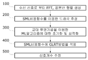
본 발명의 과정을 요약하면 다음과 같다. 우선, 수신신호의 공분산행렬에 SML 비용함수를 이용하여 초기 도래각 추정치를 결정한다. 초기의 신호개수는 1개로 설정한다. 결정된 초기 도래각 추정치를 이용해서 SML 비용함수에 GLRT 방법을 적용하여서 신호개수를 추정한다. 추정치가 특정 문턱값(threshold)보다 클 경우, 신호개수를 하나 추가한 후 교대투영 기법을 이용해서 도래각 추정을 계속적으로 수행한다. 문턱값보다 크지 않을 경우에는 신호개수 추정을 종료한다.The process of the present invention is summarized as follows. First, an initial arrival angle estimate is determined by using the SML cost function in the covariance matrix of the received signal. The initial number of signals is set to one. Using the determined initial arrival angle estimate, the number of signals is estimated by applying the GLRT method to the SML cost function. If the estimate is greater than a certain threshold, the number of signals is added, and then the angle of arrival is continuously performed using an alternating projection technique. If it is not greater than the threshold, the number of signals is estimated.
본 발명의 과정을 좀 더 구체적으로 소개하면 다음과 같다. When introducing the process of the present invention in more detail as follows.
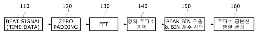
수신신호로부터 FFT를 실행하여 공분산행렬을 생성한다. 공분산 행렬 생성 과정을 살펴보면, 먼저 시간 데이터(time data)인 수신신호, 즉, 비트신호(beat signal)를 제로패딩(zero padding)한 후에 고속퓨리어변환(FFT)을 수행하고 양의 주파수영역을 취하여 Peak Bin을 추출하고 Bin 개수를 선택한다. 이 과정을 통해서 주파수 공분산행렬을 생성한다.FFT is executed from the received signal to generate a covariance matrix. Looking at the process of generating the covariance matrix, first, a zero signal is padded to a received signal that is time data, that is, a beat signal, and then a fast Fourier transform (FFT) is performed and a positive frequency domain is generated. Take and extract the peak bin and select the number of bins. Through this process, a frequency covariance matrix is generated.
다음에 위와 같이 생성된 수신신호의 공분산 행렬을 SML 비용함수에 적용해서 도래각을 추정한다. ULA 안테나를 사용하는 경우에 평면파로 입사하는 수신신호들은 각각의 성분 안테나에 대해 같은 도래각(DoA) 정보를 가지고 있으며, 도래각 추정을 위한 SML 비용함수를 정의하기 위해서는 어레이벡터(array vector)가 정의되어야 한다. 그러나 신호로부터 각각의 센서까지의 거리가 다르기 때문에 시간지연(time-delay)이 발생한다. 이를 고려하여야 한다. Next, the arrival angle is estimated by applying the covariance matrix of the received signal generated as above to the SML cost function. When a ULA antenna is used, received signals incident on a plane wave have the same arrival angle (DoA) information for each component antenna, and an array vector is used to define the SML cost function for estimating the arrival angle. Should be defined. However, since the distance from the signal to each sensor is different, time-delay occurs. This should be considered.
이어서, 교대 투영기법을 이용하여 ML 알고리즘을 초기화하고 최적화한다. 이 단계는 다음과 같은 세부단계를 포함할 수 있다. Next, the ML algorithm is initialized and optimized using an alternating projection technique. This step may include the following detailed steps.
1) 첫 입사신호의 도래각을 일정한 탐색 간격으로 변화하여 SML 비용함수 구하기1) Obtain the SML cost function by changing the arrival angle of the first incident signal at regular search intervals
2) 첫 입사신호의 초기 추정값으로 첫 도래각을 고정하기2) Fixing the first arrival angle as the initial estimate of the first incident signal
3) 두 번째 입사신호의 도래각을 일정한 탐색간격으로 변화시켜 SML 비용함수 구하기3) Obtaining the SML cost function by changing the arrival angle of the second incident signal at a constant search interval
끝으로, 도래각 추정치를 이용해서 SML 비용함수를 구하고 GLRT(Generalized Likelihood Ratio Test)를 적용하여서 최종적으로 신호의 개수를 추정한다. 신호 개수 추정을 위해서 귀무가설(Null hypothesis) 검증법을 사용할 수 있다. 귀무가설의 검증을 위해 카이제곱분포(chi-square distribution)에 기반하여 문턱값을 설정하여, 추정치가 특정 문턱값(threshold)보다 클 경우, 신호개수를 하나 추가한 후 교대투영 기법을 이용해서 도래각 추정을 계속적으로 수행하고, 문턱값보다 크지 않을 경우에는 신호개수 추정을 종료한다.Finally, the SML cost function is calculated using the arrival angle estimate, and the number of signals is finally estimated by applying the Generalized Likelihood Ratio Test (GLRT). To estimate the number of signals, the null hypothesis verification method can be used. To verify the null hypothesis, a threshold value is set based on a chi-square distribution, and if the estimate is larger than a certain threshold, add a signal number and then use an alternate projection technique to arrive. Each estimation is continuously performed, and if it is not greater than a threshold, estimation of the number of signals is terminated.
이상의 본 발명의 개시사항은 차후에 도면과 함께 구체적인 실시예를 설명함으로써 더욱 명확해질 것이다. The above disclosure of the present invention will be further clarified by describing specific embodiments with drawings in the future.
본 발명의 경우에는 기존의 알고리즘과는 달리 신호개수를 추정하는 신뢰성이 매우 높다. 수신신호를 N-point FFT한 후에 피크가 발생하는 bin과 이 Peak bin의 양 옆빈(Side bin)으로 공분산행렬을 생성하였다. 표적 거리(target range)를 고려하여서, 표적의 개수만큼 각각 공분산 행렬을 생성 후, 각각 신호개수를 추정하고 각각의 공분산행렬에 대한 신호추정 개수를 더해서 최종 신호개수를 구하였다. In the case of the present invention, unlike the conventional algorithm, the reliability of estimating the number of signals is very high. After the received signal was N-point FFT, a covariance matrix was generated with bins where peaks occur and side bins of the peak bins. Considering the target range, after generating the covariance matrix by the number of targets, the number of signals is estimated, and the number of signal estimates for each covariance matrix is added to obtain the final number of signals.
아래 표 1은 5개 bin에 대한 신호개수 추정 결과이다. Peak bin 1개와 Side bin 4개, 총 5개의 bin을 이용하여 공분산행렬을 생성했다. SML 비용함수 및 가설검증을 고려하여 -10dB, 0dB, 10dB의 SNR(신호대잡음비)에 대한 각각의 신호개수 추정 결과를 얻었다. 거리가 6m, 입사각이 -10deg인 입사신호가 1개인 시나리오와, 거리가 6m, 15m 입사각이 -10deg, 20deg인 입사신호가 2개인 시나리오와, 거리가 6m, 15m, 24m 입사각이 -10deg, 0deg, 20deg인 입사신호가 3개인 시나리오 각각에 대한 신호개수 추정 결과를 표 1에 나타내었다. Table 1 below shows the result of estimating the number of signals for 5 bins. A covariance matrix was generated using one peak bin, four side bins, and a total of five bins. Considering the SML cost function and hypothesis verification, each signal number estimation result was obtained for SNR (signal-to-noise ratio) of -10dB, 0dB, and 10dB. Scenario with one incident signal with a distance of 6 m and an incident angle of -10 deg, Scenario with two incident signals with a distance of 6 m, 15 m with an incident angle of -10 deg, 20 deg, and a distance of 6 m, 15 m, 24 m with an incident angle of -10 deg, 0 deg , Table 1 shows the result of estimating the number of signals for each scenario with three incident signals of 20 deg.
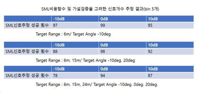
표 2는 7개의 bin에 대한 신호개수 추정 결과이다. Peak bin과 Side bin 6개, 총 7개의 bin으로 신호개수를 추정하였다. 나머지는 표 1의 시나리오와 같은 상황에서 신호개수 추정 결과를 얻었다. Table 2 shows the result of estimating the number of signals for 7 bins. The number of signals was estimated with 6 peak bins and 6 side bins. In the rest, the signal count estimation results were obtained in the same scenario as in Table 1.

도 1은 본 발명의 구성 블록도
도 2는 도 1의 공분산행렬의 생성단계(100) 구성도
도 3은 ULA 안테나의 구조도
도 4는 도 1의 신호개수 추정 단계(400 및 500)의 실행 과정도1 is a block diagram of the present invention
FIG. 2 is a block diagram showing the construction of the covariance matrix of FIG. 1 (100).
3 is a structural diagram of the ULA antenna
FIG. 4 is an execution process diagram of the signal
본 발명의 이점 및 특징, 그리고 그것들을 달성하는 방법은 첨부되는 도면과 함께 상세하게 기술되어 있는 실시예를 참조하면 명확해질 것이다. 그러나 본 발명은 이하에서 개시되는 실시예에 한정되는 것이 아니라 서로 다른 다양한 형태로 구현될 것이며, 단지 본 실시예는 본 발명의 개시가 완전하도록 하며, 본 발명이 속하는 기술분야에서 통상의 지식을 가진 자에게 발명의 범주를 완전하게 알려주기 위해 제공되는 것이며, 본 발명은 청구항의 기재에 의해 정의된다. Advantages and features of the present invention, and a method of achieving them will be made clear by referring to embodiments described in detail with reference to the accompanying drawings. However, the present invention is not limited to the embodiments disclosed below, but will be implemented in various different forms, and only the present embodiments make the disclosure of the present invention complete, and have ordinary knowledge in the technical field to which the present invention pertains. It is provided to fully inform the person of the scope of the invention, and the invention is defined by the description of the claims.
한편, 본 명세서에서 사용된 용어는 실시예를 설명하기 위한 것이며 본 발명을 제한하고자 하는 것은 아니다. 본 명세서에서, 단수형은 문구에서 특별히 언급하지 않는 한 복수형도 포함한다. 명세서에서 사용한 "포함한다(comprises)" 또는 "포함하는(comprising)"이라는 용어는 언급된 구성요소, 단계, 또는 동작 이외의 하나 이상의 다른 구성요소, 단계, 또는 동작의 존재 또는 추가를 배제하지 않는다는 의미이다.On the other hand, the terms used in this specification are for describing the embodiments and are not intended to limit the present invention. In this specification, the singular form also includes the plural form unless otherwise specified in the phrase. As used herein, the terms "comprises" or "comprising" do not exclude the presence or addition of one or more other components, steps, or actions other than the stated component, step, or action. Meaning.
이하, 본 발명의 바람직한 실시예를 첨부 도면을 참조하여 상세히 설명한다. 우선 각 도면의 구성요소들에 참조부호를 부가함에 있어서, 동일한 구성요소들에 대해서는 비록 다른 도면상에 표시되더라도 가급적 동일한 부호를 부여하고 또한 본 발명을 설명함에 있어, 관련된 공지 구성 또는 기능에 대한 구체적인 설명이 본 발명의 요지를 흐릴 수 있는 경우에는 그 상세한 설명은 생략한다.Hereinafter, preferred embodiments of the present invention will be described in detail with reference to the accompanying drawings. First, in adding reference numerals to the components of each drawing, the same components are assigned the same reference numerals as much as possible even though they are displayed on different drawings, and in describing the present invention, specifics of related well-known components or functions are described. When the description may obscure the subject matter of the present invention, the detailed description is omitted.
도 1은 본 발명의 구성 블록도로서, 본 발명에 따른 SML 비용함수 및 가설검증을 고려한 신호개수 추정 알고리즘의 구성 블록도이다. 각 단계 순서대로 설명한다. 1 is a configuration block diagram of the present invention, and is a block diagram of a signal number estimation algorithm considering SML cost function and hypothesis verification according to the present invention. Each step is explained in order.
100: 수신신호로부터 FFT를 실행하여 공분산행렬을 생성100: FFT is executed from the received signal to generate a covariance matrix
도 2는 이 공분산행렬의 생성단계(100)를 나타내고, 수학식 1은 수신신호의 시평균을 이용한 공분산행렬을 나타낸다. 도 2에서 공분산 행렬 생성 과정을 살펴보면, 먼저 시간 데이터(time data)인 수신신호, 즉, 비트신호(beat signal)(110)를 제로패딩(zero padding)한다(120). 제로패딩은 출력 사이즈를 키우고 입력 맵의 픽셀들을 좀 더 많이 스캔하기 위해서 입력 맵 주위에 값이 0 인 픽셀을 채우는 과정이다. 그 후에 고속퓨리어변환(FFT)을 수행하고(130) 양의 주파수영역을 취하여(140) Peak Bin을 추출하고 Bin 개수를 선택한다(150). 이 과정을 통해서 주파수 공분산행렬(수학식 1 참조)을 생성한다(160).2 shows a
![]()
![]()
200: 단계 100에서 도 2와 같이 생성된 수신신호의 공분산 행렬을 SML 비용함수에 적용해서 도래각을 추정.200: The arrival angle is estimated by applying the covariance matrix of the received signal generated in
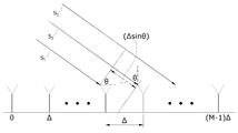
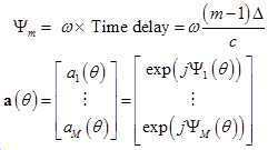
도 3은 ULA(Uniform Linear Array) 안테나를 나타낸다. ULA 안테나는 배열을 구성하는 모든 안테나를 같은 크기의 전류로 여기하고 센서간에 등간격을 유지한다. ULA 안테나의 경우 평면파로 입사하는 신호들(S1, S2, S3)은 각각의 안테나에 대해 같은 도래각(DoA) 정보(θ)를 가지고 있다. 도래각 추정을 위한 SML 비용함수를 정의하기 위해서는 어레이벡터(array vector)가 정의되어야 한다. 그러나 신호로부터 각각의 센서까지의 거리가 다르기 때문에 시간지연(time-delay)이 발생한다. 이를 반영하여서 ULA 안테나에서의 어레이벡터는 수학식 2와 같이 나타낼 수 있다.3 shows a ULA (Uniform Linear Array) antenna. The ULA antenna excites all antennas constituting the array with a current of the same size and maintains an equal distance between sensors. In the case of ULA antennas, signals S1, S2, and S3 incident as plane waves have the same angle of arrival (DoA) information θ for each antenna. To define the SML cost function for estimating the arrival angle, an array vector must be defined. However, since the distance from the signal to each sensor is different, time-delay occurs. Reflecting this, the array vector in the ULA antenna can be expressed as Equation 2.
수학식 3은 SML 비용함수를 유도하기 위한 안테나 센서응답을 나타낸다.Equation 3 shows the antenna sensor response for deriving the SML cost function.
![]()
![]()
샘플링된 안테나 센서응답값을 고속퓨리에 변환하면 수학식 4와 같이 안테나 센서 응답을 나타낼 수 있다.When the sampled antenna sensor response value is transformed by a fast Fourier, the antenna sensor response can be expressed as in Equation 4.

여기서 ![]()
![]()
![]()
![]()
첫번째 도래각에서의 공분산행렬은 수학식 5와 같다.The covariance matrix at the first angle of arrival is shown in Equation 5.
![]()
![]()
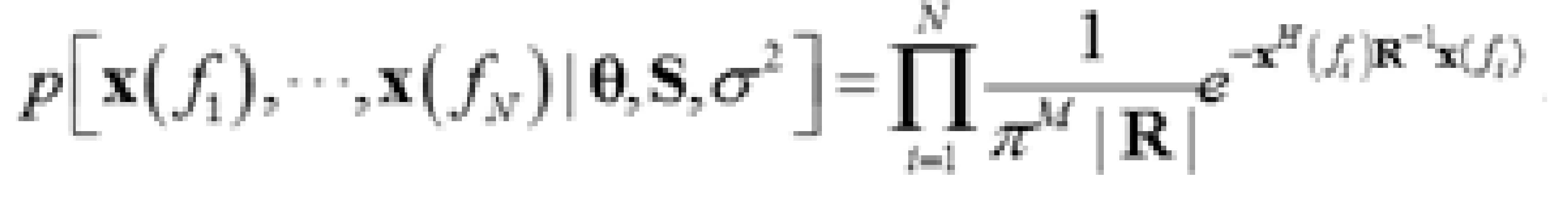
공분산 행렬을 이용하여서 한 번의 관측 ![]()
![]()

![]()
![]()
![]()
![]()

수학식 8에서 ![]()
![]()

또한, 수학식 7의 ![]()
![]()
![]()
![]()
수학식 10에서 ![]()
![]()
![]()
![]()
![]()
![]()
![]()
![]()
한편, 수학식 11에서 ![]()
![]()
![]()
![]()
![]()
![]()
![]()
![]()
![]()
![]()
300: 교대 투영기법을 이용한 ML알고리즘에 대한 초기화 및 최적화300: Initialization and optimization of ML algorithm using alternating projection technique
이 단계는 다음과 같은 세부단계를 포함한다. This step includes the following detailed steps.
1) 첫 입사신호의 도래각을 일정한 탐색 간격으로 변화하여 SML 비용함수 구하기1) Obtain the SML cost function by changing the arrival angle of the first incident signal at regular search intervals
2) 첫 입사신호의 초기 추정값으로 첫 도래각을 고정하기2) Fixing the first arrival angle as the initial estimate of the first incident signal
3) 두 번째 입사신호의 도래각을 일정한 탐색간격으로 변화시켜 SML 비용함수 구하기3) Obtaining the SML cost function by changing the arrival angle of the second incident signal at a constant search interval
수학식 14는 최초 신호의 도래각 추정치 및 두 번째 신호의 도래각 추정치를 나타낸다.Equation 14 shows the arrival angle estimate of the first signal and the arrival angle estimate of the second signal.

400: 도래각 추정치를 이용해서 SML 비용함수를 구하고 GLRT(Generalized Likelihood Ratio Test)를 적용. 400: SML cost function is calculated using the estimated angle of arrival, and GLRT (Generalized Likelihood Ratio Test) is applied.
500: 신호의 개수를 추정.500: Estimate the number of signals.
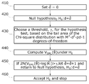
도 4는 도래각 추정치를 이용하여 신호개수를 추정하는 단계 400 및 500의 실행 과정을 나타낸다. 이하에서 사용된 변수 표기는 아래와 같다.4 shows an execution process of

410: ![]()
![]()
420: ![]()
![]()
![]()
![]()
430: 위 귀무가설의 검증을 위해 ![]()
![]()
![]()
![]()
440: 상기 H0 하에서 수학식 13의 ![]()
![]()
450: 만일 ![]()
![]()
![]()
![]()
![]()
![]()
![]()
![]()
460: 상기 단계에서 ![]()
![]()
![]()
![]()
이상 본 발명의 방법적 실시예에서 설명한 구성요소들은, DSP(digital signal processor), 프로세서, 컨트롤러, ASIC(application-specific IC), 프로그래머블 로직소자(FPGA 등), 기타 전자소자 중의 적어도 하나 그리고 이들의 조합이 포함되는 하드웨어 요소로써 실현가능하다. 또한 본 발명의 방법적 실시예에서 설명한 기능(function) 또는 과정(process)은 소프트웨어로써 실현가능한데, 이 소프트웨어는 기록매체에 저장가능하다. 그리고 본 발명의 상기 방법적 실시예에서 설명한 구성요소, 기능, 과정은 하드웨어와 소프트웨어를 결합하여 실현가능하다. The components described in the method embodiments of the present invention are at least one of a digital signal processor (DSP), a processor, a controller, an application-specific IC (ASIC), a programmable logic device (FPGA, etc.), and other electronic devices, and It is feasible as a hardware element that includes a combination. Also, the functions or processes described in the method embodiments of the present invention can be realized by software, which can be stored in a recording medium. And the components, functions, and processes described in the method embodiment of the present invention can be realized by combining hardware and software.
이상, 본 발명의 바람직한 실시예를 통하여 본 발명의 구성을 상세히 설명하였으나, 본 발명이 속하는 기술분야의 통상의 지식을 가진 자는 본 발명이 그 기술적 사상이나 필수적인 특징을 변경하지 않고서 본 명세서에 개시된 내용과는 다른 구체적인 형태로 실시될 수 있다는 것을 이해할 수 있을 것이다. 이상에서 기술한 실시예들은 모든 면에서 예시적인 것이며 제한적이지 않은 것으로 이해해야만 한다. 본 발명의 보호범위는 상기 상세한 설명보다는 후술한 특허청구범위에 의하여 정해지며, 특허청구의 범위 그리고 그 균등 개념으로부터 도출되는 모든 변경 또는 변형된 형태는 본 발명의 기술적 범위에 포함되는 것으로 해석되어야 한다.The configuration of the present invention has been described in detail through preferred embodiments of the present invention, but those skilled in the art to which the present invention pertains are disclosed herein without changing the technical spirit or essential features of the present invention. It will be understood that the lesson may be implemented in other specific forms. It should be understood that the embodiments described above are illustrative in all respects and not restrictive. The protection scope of the present invention is defined by the claims below, rather than by the detailed description, and all changes or modifications derived from the claims and equivalent concepts should be interpreted to be included in the technical scope of the present invention. .
Claims (1)
결정된 초기 도래각 추정치를 이용해서 SML 비용함수에 GLRT 방법을 적용하여서 신호개수를 추정하되, 추정치가 문턱값보다 클 경우, 신호개수를 하나 추가한 후 교대투영 기법을 이용해서 도래각 추정을 계속적으로 수행하고, 문턱값보다 크지 않을 경우에는 신호개수 추정을 종료하는 단계를 포함하는, SML 비용함수 및 가설검증을 고려한 신호개수 추정 방법.Determining an initial arrival angle estimate using the SML cost function in the covariance matrix of the received signal,
Using the determined initial arrival angle estimate, the number of signals is estimated by applying the GLRT method to the SML cost function, but if the estimate is larger than the threshold value, the number of signals is added and then the shift angle estimation is continuously performed using the alternate projection technique. Performing, and if not greater than the threshold value, including the step of ending the signal count estimation, SML cost function and the signal number estimation method considering the hypothesis verification.
Priority Applications (1)
| Application Number | Priority Date | Filing Date | Title |
|---|---|---|---|
| KR1020180113008A KR102471995B1 (en) | 2018-09-20 | 2018-09-20 | Method and apparatus for estimating the number of signals, by considering SML cost function and hypothesis test |
Applications Claiming Priority (1)
| Application Number | Priority Date | Filing Date | Title |
|---|---|---|---|
| KR1020180113008A KR102471995B1 (en) | 2018-09-20 | 2018-09-20 | Method and apparatus for estimating the number of signals, by considering SML cost function and hypothesis test |
Publications (2)
| Publication Number | Publication Date |
|---|---|
| KR20200033571A true KR20200033571A (en) | 2020-03-30 |
| KR102471995B1 KR102471995B1 (en) | 2022-11-30 |
Family
ID=70003472
Family Applications (1)
| Application Number | Title | Priority Date | Filing Date |
|---|---|---|---|
| KR1020180113008A KR102471995B1 (en) | 2018-09-20 | 2018-09-20 | Method and apparatus for estimating the number of signals, by considering SML cost function and hypothesis test |
Country Status (1)
| Country | Link |
|---|---|
| KR (1) | KR102471995B1 (en) |
Cited By (1)
| Publication number | Priority date | Publication date | Assignee | Title |
|---|---|---|---|---|
| KR20220154962A (en) | 2021-05-14 | 2022-11-22 | 국방과학연구소 | A method and apparatus for signal estimation using the gap of the eigenvalues of the covariance matrix for the received signal and the average of the gap |
Citations (4)
| Publication number | Priority date | Publication date | Assignee | Title |
|---|---|---|---|---|
| KR20080063000A (en) * | 2006-12-29 | 2008-07-03 | 세종대학교산학협력단 | Apparatus for estimation of alternating projection searching and method thereof |
| KR100912251B1 (en) * | 2009-02-25 | 2009-08-17 | 국방과학연구소 | Method for estimating direction of arrival, method for detecting target and apparatus for estimating direction of arrival |
| KR20160012284A (en) * | 2014-07-23 | 2016-02-03 | 국방과학연구소 | Method and Apparatus for suppressing jammer signals and estimating Angle Of Arrival of original signal using orthogonal of transmitting signal waveform |
| KR101783777B1 (en) * | 2016-05-17 | 2017-10-10 | 국방과학연구소 | Method for estimating direction of arrival using covariance fitting |
-
2018
- 2018-09-20 KR KR1020180113008A patent/KR102471995B1/en active IP Right Grant
Patent Citations (4)
| Publication number | Priority date | Publication date | Assignee | Title |
|---|---|---|---|---|
| KR20080063000A (en) * | 2006-12-29 | 2008-07-03 | 세종대학교산학협력단 | Apparatus for estimation of alternating projection searching and method thereof |
| KR100912251B1 (en) * | 2009-02-25 | 2009-08-17 | 국방과학연구소 | Method for estimating direction of arrival, method for detecting target and apparatus for estimating direction of arrival |
| KR20160012284A (en) * | 2014-07-23 | 2016-02-03 | 국방과학연구소 | Method and Apparatus for suppressing jammer signals and estimating Angle Of Arrival of original signal using orthogonal of transmitting signal waveform |
| KR101783777B1 (en) * | 2016-05-17 | 2017-10-10 | 국방과학연구소 | Method for estimating direction of arrival using covariance fitting |
Cited By (1)
| Publication number | Priority date | Publication date | Assignee | Title |
|---|---|---|---|---|
| KR20220154962A (en) | 2021-05-14 | 2022-11-22 | 국방과학연구소 | A method and apparatus for signal estimation using the gap of the eigenvalues of the covariance matrix for the received signal and the average of the gap |
Also Published As
| Publication number | Publication date |
|---|---|
| KR102471995B1 (en) | 2022-11-30 |
Similar Documents
| Publication | Publication Date | Title |
|---|---|---|
| Tirer et al. | High resolution direct position determination of radio frequency sources | |
| KR101562904B1 (en) | Direction of Arrival Estimation Apparatus and Method therof | |
| JP5600866B2 (en) | Detecting and ranging apparatus and detecting and ranging method | |
| JP4709117B2 (en) | Radar device and angle measuring device | |
| US8669901B2 (en) | Method for determining azimuth and elevation angles of arrival of coherent sources | |
| JP2019117055A (en) | Estimation method, estimation device and program | |
| AU2014412888A1 (en) | Methods and systems for spectral analysis of sonar data | |
| CN103616661B (en) | A kind of sane far-field narrowband signal source number estimation method | |
| KR102262197B1 (en) | Apparatus and method for estimating the shape of a target using fmcw radar signals | |
| EP3742189A1 (en) | System and method for detecting pulses using fused threshold/ phase modulation detection | |
| KR20160012284A (en) | Method and Apparatus for suppressing jammer signals and estimating Angle Of Arrival of original signal using orthogonal of transmitting signal waveform | |
| CN111007487B (en) | Multi-base radar target detection method based on time reversal | |
| JP2010127771A (en) | Synthetic aperture sonar, and method and program for correcting phase error of synthetic aperture sonar | |
| KR102577357B1 (en) | Method and apparatus for estimating the number of signals in radar system | |
| KR102099388B1 (en) | Method of estimating direction of arrival of radar signal based on antenna array extrapolation and apparatus for the same | |
| KR102471995B1 (en) | Method and apparatus for estimating the number of signals, by considering SML cost function and hypothesis test | |
| US6744407B2 (en) | Method and device for space-time estimation of one or more transmitters | |
| US11474194B2 (en) | Controlling a device by tracking movement of hand using acoustic signals | |
| KR102097080B1 (en) | Multiple transmit/receive array antenna radar apparatus and method using virtual channel | |
| Olbrich et al. | New pre-estimation algorithm for FMCW radar systems using the matrix pencil method | |
| CN116148756A (en) | Method and device for determining a direction of arrival angle | |
| KR20190124488A (en) | Method of signal subspace based DoA estimation for automotive radar system | |
| JP7397383B2 (en) | Doppler compensation system and Doppler compensation method | |
| JP2002048859A (en) | Radar device for target identification | |
| JPH06347530A (en) | Estimation system for sound source position in water |
Legal Events
| Date | Code | Title | Description |
|---|---|---|---|
| A201 | Request for examination | ||
| E701 | Decision to grant or registration of patent right |