KR20200032151A - Electrolytic device - Google Patents
Electrolytic device Download PDFInfo
- Publication number
- KR20200032151A KR20200032151A KR1020207004731A KR20207004731A KR20200032151A KR 20200032151 A KR20200032151 A KR 20200032151A KR 1020207004731 A KR1020207004731 A KR 1020207004731A KR 20207004731 A KR20207004731 A KR 20207004731A KR 20200032151 A KR20200032151 A KR 20200032151A
- Authority
- KR
- South Korea
- Prior art keywords
- anode
- cathode
- gas
- storage tank
- hydrogen gas
- Prior art date
Links
Images


Classifications
-
- C—CHEMISTRY; METALLURGY
- C25—ELECTROLYTIC OR ELECTROPHORETIC PROCESSES; APPARATUS THEREFOR
- C25B—ELECTROLYTIC OR ELECTROPHORETIC PROCESSES FOR THE PRODUCTION OF COMPOUNDS OR NON-METALS; APPARATUS THEREFOR
- C25B1/00—Electrolytic production of inorganic compounds or non-metals
- C25B1/01—Products
- C25B1/02—Hydrogen or oxygen
- C25B1/04—Hydrogen or oxygen by electrolysis of water
- C25B1/044—Hydrogen or oxygen by electrolysis of water producing mixed hydrogen and oxygen gas, e.g. Brown's gas [HHO]
-
- C—CHEMISTRY; METALLURGY
- C25—ELECTROLYTIC OR ELECTROPHORETIC PROCESSES; APPARATUS THEREFOR
- C25B—ELECTROLYTIC OR ELECTROPHORETIC PROCESSES FOR THE PRODUCTION OF COMPOUNDS OR NON-METALS; APPARATUS THEREFOR
- C25B1/00—Electrolytic production of inorganic compounds or non-metals
- C25B1/01—Products
- C25B1/02—Hydrogen or oxygen
- C25B1/04—Hydrogen or oxygen by electrolysis of water
-
- C25B1/10—
-
- C—CHEMISTRY; METALLURGY
- C01—INORGANIC CHEMISTRY
- C01B—NON-METALLIC ELEMENTS; COMPOUNDS THEREOF; METALLOIDS OR COMPOUNDS THEREOF NOT COVERED BY SUBCLASS C01C
- C01B3/00—Hydrogen; Gaseous mixtures containing hydrogen; Separation of hydrogen from mixtures containing it; Purification of hydrogen
- C01B3/50—Separation of hydrogen or hydrogen containing gases from gaseous mixtures, e.g. purification
-
- C—CHEMISTRY; METALLURGY
- C25—ELECTROLYTIC OR ELECTROPHORETIC PROCESSES; APPARATUS THEREFOR
- C25B—ELECTROLYTIC OR ELECTROPHORETIC PROCESSES FOR THE PRODUCTION OF COMPOUNDS OR NON-METALS; APPARATUS THEREFOR
- C25B15/00—Operating or servicing cells
- C25B15/02—Process control or regulation
-
- C—CHEMISTRY; METALLURGY
- C25—ELECTROLYTIC OR ELECTROPHORETIC PROCESSES; APPARATUS THEREFOR
- C25B—ELECTROLYTIC OR ELECTROPHORETIC PROCESSES FOR THE PRODUCTION OF COMPOUNDS OR NON-METALS; APPARATUS THEREFOR
- C25B15/00—Operating or servicing cells
- C25B15/08—Supplying or removing reactants or electrolytes; Regeneration of electrolytes
- C25B15/085—Removing impurities
-
- C—CHEMISTRY; METALLURGY
- C25—ELECTROLYTIC OR ELECTROPHORETIC PROCESSES; APPARATUS THEREFOR
- C25B—ELECTROLYTIC OR ELECTROPHORETIC PROCESSES FOR THE PRODUCTION OF COMPOUNDS OR NON-METALS; APPARATUS THEREFOR
- C25B15/00—Operating or servicing cells
- C25B15/08—Supplying or removing reactants or electrolytes; Regeneration of electrolytes
- C25B15/087—Recycling of electrolyte to electrochemical cell
-
- C—CHEMISTRY; METALLURGY
- C25—ELECTROLYTIC OR ELECTROPHORETIC PROCESSES; APPARATUS THEREFOR
- C25B—ELECTROLYTIC OR ELECTROPHORETIC PROCESSES FOR THE PRODUCTION OF COMPOUNDS OR NON-METALS; APPARATUS THEREFOR
- C25B9/00—Cells or assemblies of cells; Constructional parts of cells; Assemblies of constructional parts, e.g. electrode-diaphragm assemblies; Process-related cell features
- C25B9/17—Cells comprising dimensionally-stable non-movable electrodes; Assemblies of constructional parts thereof
- C25B9/19—Cells comprising dimensionally-stable non-movable electrodes; Assemblies of constructional parts thereof with diaphragms
- C25B9/23—Cells comprising dimensionally-stable non-movable electrodes; Assemblies of constructional parts thereof with diaphragms comprising ion-exchange membranes in or on which electrode material is embedded
-
- C—CHEMISTRY; METALLURGY
- C25—ELECTROLYTIC OR ELECTROPHORETIC PROCESSES; APPARATUS THEREFOR
- C25B—ELECTROLYTIC OR ELECTROPHORETIC PROCESSES FOR THE PRODUCTION OF COMPOUNDS OR NON-METALS; APPARATUS THEREFOR
- C25B9/00—Cells or assemblies of cells; Constructional parts of cells; Assemblies of constructional parts, e.g. electrode-diaphragm assemblies; Process-related cell features
- C25B9/70—Assemblies comprising two or more cells
- C25B9/73—Assemblies comprising two or more cells of the filter-press type
-
- F—MECHANICAL ENGINEERING; LIGHTING; HEATING; WEAPONS; BLASTING
- F04—POSITIVE - DISPLACEMENT MACHINES FOR LIQUIDS; PUMPS FOR LIQUIDS OR ELASTIC FLUIDS
- F04F—PUMPING OF FLUID BY DIRECT CONTACT OF ANOTHER FLUID OR BY USING INERTIA OF FLUID TO BE PUMPED; SIPHONS
- F04F5/00—Jet pumps, i.e. devices in which flow is induced by pressure drop caused by velocity of another fluid flow
- F04F5/02—Jet pumps, i.e. devices in which flow is induced by pressure drop caused by velocity of another fluid flow the inducing fluid being liquid
- F04F5/04—Jet pumps, i.e. devices in which flow is induced by pressure drop caused by velocity of another fluid flow the inducing fluid being liquid displacing elastic fluids
-
- F—MECHANICAL ENGINEERING; LIGHTING; HEATING; WEAPONS; BLASTING
- F17—STORING OR DISTRIBUTING GASES OR LIQUIDS
- F17C—VESSELS FOR CONTAINING OR STORING COMPRESSED, LIQUEFIED OR SOLIDIFIED GASES; FIXED-CAPACITY GAS-HOLDERS; FILLING VESSELS WITH, OR DISCHARGING FROM VESSELS, COMPRESSED, LIQUEFIED, OR SOLIDIFIED GASES
- F17C5/00—Methods or apparatus for filling containers with liquefied, solidified, or compressed gases under pressures
- F17C5/06—Methods or apparatus for filling containers with liquefied, solidified, or compressed gases under pressures for filling with compressed gases
-
- B—PERFORMING OPERATIONS; TRANSPORTING
- B01—PHYSICAL OR CHEMICAL PROCESSES OR APPARATUS IN GENERAL
- B01D—SEPARATION
- B01D2252/00—Absorbents, i.e. solvents and liquid materials for gas absorption
- B01D2252/10—Inorganic absorbents
- B01D2252/103—Water
-
- B—PERFORMING OPERATIONS; TRANSPORTING
- B01—PHYSICAL OR CHEMICAL PROCESSES OR APPARATUS IN GENERAL
- B01D—SEPARATION
- B01D2256/00—Main component in the product gas stream after treatment
- B01D2256/16—Hydrogen
-
- F—MECHANICAL ENGINEERING; LIGHTING; HEATING; WEAPONS; BLASTING
- F17—STORING OR DISTRIBUTING GASES OR LIQUIDS
- F17C—VESSELS FOR CONTAINING OR STORING COMPRESSED, LIQUEFIED OR SOLIDIFIED GASES; FIXED-CAPACITY GAS-HOLDERS; FILLING VESSELS WITH, OR DISCHARGING FROM VESSELS, COMPRESSED, LIQUEFIED, OR SOLIDIFIED GASES
- F17C2221/00—Handled fluid, in particular type of fluid
- F17C2221/01—Pure fluids
- F17C2221/012—Hydrogen
-
- Y—GENERAL TAGGING OF NEW TECHNOLOGICAL DEVELOPMENTS; GENERAL TAGGING OF CROSS-SECTIONAL TECHNOLOGIES SPANNING OVER SEVERAL SECTIONS OF THE IPC; TECHNICAL SUBJECTS COVERED BY FORMER USPC CROSS-REFERENCE ART COLLECTIONS [XRACs] AND DIGESTS
- Y02—TECHNOLOGIES OR APPLICATIONS FOR MITIGATION OR ADAPTATION AGAINST CLIMATE CHANGE
- Y02E—REDUCTION OF GREENHOUSE GAS [GHG] EMISSIONS, RELATED TO ENERGY GENERATION, TRANSMISSION OR DISTRIBUTION
- Y02E60/00—Enabling technologies; Technologies with a potential or indirect contribution to GHG emissions mitigation
- Y02E60/30—Hydrogen technology
- Y02E60/32—Hydrogen storage
-
- Y—GENERAL TAGGING OF NEW TECHNOLOGICAL DEVELOPMENTS; GENERAL TAGGING OF CROSS-SECTIONAL TECHNOLOGIES SPANNING OVER SEVERAL SECTIONS OF THE IPC; TECHNICAL SUBJECTS COVERED BY FORMER USPC CROSS-REFERENCE ART COLLECTIONS [XRACs] AND DIGESTS
- Y02—TECHNOLOGIES OR APPLICATIONS FOR MITIGATION OR ADAPTATION AGAINST CLIMATE CHANGE
- Y02E—REDUCTION OF GREENHOUSE GAS [GHG] EMISSIONS, RELATED TO ENERGY GENERATION, TRANSMISSION OR DISTRIBUTION
- Y02E60/00—Enabling technologies; Technologies with a potential or indirect contribution to GHG emissions mitigation
- Y02E60/30—Hydrogen technology
- Y02E60/36—Hydrogen production from non-carbon containing sources, e.g. by water electrolysis
Landscapes
- Chemical & Material Sciences (AREA)
- Engineering & Computer Science (AREA)
- Organic Chemistry (AREA)
- Chemical Kinetics & Catalysis (AREA)
- Electrochemistry (AREA)
- Materials Engineering (AREA)
- Metallurgy (AREA)
- Inorganic Chemistry (AREA)
- Life Sciences & Earth Sciences (AREA)
- Sustainable Development (AREA)
- Mechanical Engineering (AREA)
- General Engineering & Computer Science (AREA)
- Physics & Mathematics (AREA)
- Fluid Mechanics (AREA)
- Combustion & Propulsion (AREA)
- Automation & Control Theory (AREA)
- Electrolytic Production Of Non-Metals, Compounds, Apparatuses Therefor (AREA)
- Jet Pumps And Other Pumps (AREA)
Abstract
전해 장치에 의해 생성된 수소 가스를 가압함과 함께, 생성된 수소 가스 중의 불순물을 제거할 수 있는 전해 장치를 제공한다. 전해에 의해 생성하는 수소 가스의 배출 라인(12)에, 이젝터(110)와 순환용 액체를 저류하는 저류 탱크(103)와 수소 가스와 순환용 액체의 혼합 유체를 이젝터에 순환시키는 순환 파이프(105)와 순환 펌프(104)로 이루어지는 기체 압축 수단(101)을 형성하고, 저류 탱크(103)에 수소 가스 배출 파이프(106)와 제1 밸브(V1)를 형성하고, 수소 가스 중의 불순물을 순환용 액체로 이행시켜 수소 가스로부터 불순물을 제거함과 함께, 저류 탱크(103)로부터 이젝터(110)로 순환시키는 순환용 액체의 유속과, 제1 밸브(V1)의 개폐를 제어함으로써, 저류 탱크(103) 내에 저류되는 수소 가스의 압력을 승압하는 전해 장치.There is provided an electrolytic device capable of removing impurities in the generated hydrogen gas while pressurizing the hydrogen gas generated by the electrolytic device. In the discharge line 12 of hydrogen gas generated by electrolysis, a reservoir tank 103 for storing the ejector 110 and a circulation liquid, and a circulation pipe 105 for circulating a mixed fluid of hydrogen gas and a circulation liquid to the ejector ) And a gas compression means 101 consisting of a circulation pump 104, a hydrogen gas discharge pipe 106 and a first valve V1 are formed in the storage tank 103, and impurities in the hydrogen gas are circulated. The storage tank 103 is controlled by controlling the flow rate of the circulating liquid circulating from the storage tank 103 to the ejector 110 and opening and closing of the first valve V1 while removing impurities from the hydrogen gas by transferring to the liquid. An electrolytic device that boosts the pressure of hydrogen gas stored therein.
Description
본 발명은, 전해에 의해 수소 가스를 생성하는 전해 장치에 관한 것이다.The present invention relates to an electrolytic device that generates hydrogen gas by electrolysis.
알칼리 수전해, 비(非)정제수의 전해, 식염 전해, 염화물 수용액, 브롬산 수용액, 염산, 황산 수용액의 전해 등에서는, 전해에 의해 음극실로부터 수소 가스가 발생한다.In alkaline electrolysis, non-purified water electrolysis, salt electrolysis, chloride aqueous solution, bromic acid aqueous solution, electrolysis of hydrochloric acid and sulfuric acid aqueous solution, hydrogen gas is generated from the cathode chamber by electrolysis.
수소 가스를 발생하는 전해 장치 및 전해 방법의 일 예로서, 특허문헌 1에 기재되는 알칼리 수전해 장치 및 알칼리 수전해 방법이 있다. 특허문헌 1의 전해 장치 및 전해 방법에서는, 양극실 및 음극실에서 생성하는 기액 혼합 유체로 이루어지는 양극액 및 음극액을 공통의 순환 탱크에 회수하고, 당해 순환 탱크 내에 있어서 혼합한 후, 양극실과 음극실의 양 전해실에 순환 공급한다. 순환 탱크에서 양극액 및 음극액을 혼합함으로써, 양 전해실 내에 공급하는 전해액의 농도를 동일한 농도로 함과 함께, 항상 일정 농도로 유지하면서 연속 전해를 행하고 있다.As an example of an electrolytic device and an electrolytic method for generating hydrogen gas, there is an alkali water electrolytic device and an alkali water electrolytic method described in
최근, 지구 온난화 방지를 위해 화석 연료로부터의 탈각(escape)이 중요해지고 있어, 대체 에너지원으로서 수소 가스의 이용이 널리 검토되고 있다. 상기의 전해에 의해 생성한 고순도의 수소 가스는, 예를 들면 특허문헌 2에 개시되어 있는 바와 같이, 저장 등의 다음의 공정으로 이송하기 위해, 압축기에 의해 가압하는 것이 요구되고 있다.In recent years, escape from fossil fuels has become important to prevent global warming, and the use of hydrogen gas as an alternative energy source has been widely considered. The high-purity hydrogen gas produced by the above electrolysis is required to be pressurized by a compressor in order to be transferred to the next step such as storage, for example, as disclosed in Patent Document 2.
알칼리 수전해, 비정제수의 전해, 식염 전해, 염화물 수용액, 브롬화물 수용액, 염산, 황산 수용액 등의 전해에서는, 전해에 의해 음극실로부터 수소 가스가 생성됨과 함께 양극실로부터 산소 가스, 오존 가스 및 또는 염소 가스가 생성된다. 산소 가스는 대기 방출되는 경우도 있는가 하면, 회수하여 다른 용도에 제공되는 경우도 있고, 오존 가스 및 염소 가스는, 회수되어 사용된다.In electrolysis such as alkaline water electrolysis, non-purified water electrolysis, salt electrolysis, chloride aqueous solution, bromide aqueous solution, hydrochloric acid, and sulfuric acid aqueous solution, hydrogen gas is generated from the cathode chamber by electrolysis and oxygen gas, ozone gas, and / or from the anode chamber. Chlorine gas is produced. Oxygen gas may be released into the atmosphere, or it may be recovered and provided to other uses, and ozone gas and chlorine gas are recovered and used.
상기한 바와 같은 종래의 전해 장치에서는, 대기압하에 있어서 생성된 기체를 가압하기 위해, 압축기가 사용되고 있다. 압축기에는, 터보 압축기와 용적 압축기가 있고, 모두 대형의 장치이다. 따라서, 넓은 설비 면적이 필요하고, 설비 비용이 높고, 추가로 소음이 문제시 되고 있었다.In the conventional electrolytic apparatus as described above, a compressor is used to pressurize the gas generated under atmospheric pressure. The compressor includes a turbo compressor and a volume compressor, both of which are large-sized devices. Therefore, a large installation area is required, the installation cost is high, and noise is additionally a problem.
또한, 상기 종래의 전해 장치에 있어서는, 기액 분리 장치에 의해 수소 가스나 산소 가스가 전해액으로부터 분리된다. 알칼리 수전해 장치에 있어서는, 순환 탱크에 있어서 혼합된 알칼리 전해액이 혼합되고, 양극실 및 음극실에 있어서 순환 사용되기 때문에, 이때, 수소 가스 및 산소 가스에는, 알칼리성 미스트나 파티클 등의 불순물이 함유되어 있다.In addition, in the conventional electrolytic device, hydrogen gas or oxygen gas is separated from the electrolytic solution by a gas-liquid separation device. In the alkaline water electrolytic apparatus, since the mixed alkaline electrolyte is mixed in the circulation tank and circulated for use in the anode chamber and the cathode chamber, hydrogen gas and oxygen gas contain impurities such as alkaline mist and particles. have.
또한, 식염 전해에 있어서는, 양극액과 음극액은, 순환하지 않고 사용되는 경우와, 순환 사용되는 경우가 있지만, 어느 경우에 있어서도, 음극실에 있어서는, 전해액은 알칼리성이 되고, 음극실에서 생성되는 수소 가스에는, 알칼리성 미스트 등의 불순물이 함유됨과 함께, 양극실에 있어서는, 전해액은 산성이 되고, 양극실에서 생성되는 산소 가스에는, 산(酸) 미스트 등의 불순물이 함유된다.In addition, in salt electrolysis, the anolyte solution and the catholyte solution may be used without circulation and may be used in circulation, but in any case, in the cathode chamber, the electrolyte solution becomes alkaline and is produced in the cathode chamber. The hydrogen gas contains impurities such as alkaline mist, and in the anode chamber, the electrolyte solution becomes acidic, and the oxygen gas generated in the anode chamber contains impurities such as acid mist.
전해액으로부터 분리된 수소 가스나 산소 가스는, 수 세정탑(water washing tower)에 의해 세정되어, 알칼리성 미스트, 산 미스트 등의 불순물이 제거되고 있었다. 그러나, 수 세정탑과 라인 중의 미스트 세퍼레이터 등의 간단한 설비에서는, 알칼리성 미스트 등의 불순물을 충분히 제거할 수 없었다. 이 때문에, 압축기의 부품에 알루미늄을 사용한 경우, 알칼리성 미스트에 의해 알루미늄이 부식된다는 문제가 있었다. 또한, 가스에 포함되는 파티클이 압축기의 운전에 영향을 주고 있었다.Hydrogen gas and oxygen gas separated from the electrolytic solution were washed by a water washing tower, and impurities such as alkaline mist and acid mist were removed. However, in simple facilities such as a water washing tower and a mist separator in a line, impurities such as alkaline mist cannot be sufficiently removed. For this reason, when aluminum is used for the components of the compressor, there is a problem that aluminum is corroded by alkaline mist. In addition, the particles contained in the gas were affecting the operation of the compressor.
또한, 생성 가스 중의 알칼리성 미스트, 산성 미스트의 제거가 불충분하면, 환경 기준을 초과하는 알칼리나 산이 대기 방출될 우려가 있었다.In addition, if the removal of the alkaline mist and acid mist in the product gas is insufficient, there is a fear that the alkali or acid exceeding the environmental standard is released into the atmosphere.
본 발명의 목적은, 이들 종래 기술의 문제점을 해소하여, 설치 면적이 작고 염가인 설비에 의해, 전해 장치에 의해 생성된 수소 가스를 가압함과 함께, 생성된 수소 가스 중의 알칼리성 미스트 등의 불순물을 제거할 수 있는 전해 장치를 제공하는 것에 있다.The object of the present invention is to solve these problems of the prior art, pressurize the hydrogen gas generated by the electrolytic apparatus, and install impurities such as alkaline mists in the generated hydrogen gas by using a small installation area and inexpensive equipment. It is to provide an electrolytic device that can be removed.
본 발명에 있어서의 제1 해결 수단은, 상기의 목적을 달성하기 위해,The first solution means in the present invention, in order to achieve the above object,
양극을 수용하는 양극실과, 음극을 수용하는 음극실과, 상기 양극실과 상기 음극실을 구획하는 격막을 구비하는 전해조와,An electrolytic cell having an anode chamber accommodating the anode, a cathode chamber accommodating the cathode, and a diaphragm partitioning the anode chamber and the cathode chamber,
상기 음극실에 접속하고, 수소 가스를 포함하는 음극측 전해액을 상기 음극실로부터 배출하는 음극측 전해액 배출 라인과,A cathode-side electrolyte discharge line that is connected to the cathode chamber and discharges a cathode-side electrolyte containing hydrogen gas from the cathode chamber;
상기 음극측 전해액 배출 라인에 접속하고, 상기 음극측 전해액으로부터 상기 수소 가스를 분리하는 음극측 기액 분리 수단과,A cathode-side gas-liquid separation means for connecting to the cathode-side electrolyte discharge line and separating the hydrogen gas from the cathode-side electrolyte;
상기 음극측 기액 분리 수단에 접속하고, 상기 음극측 기액 분리 수단에 의해 분리된 상기 수소 가스를 상기 음극측 기액 분리 수단으로부터 배출하는 수소 가스 배출 라인과,A hydrogen gas discharge line connected to the cathode-side gas-liquid separation means and discharging the hydrogen gas separated by the cathode-side gas-liquid separation means from the cathode-side gas-liquid separation means;
상기 수소 가스 배출 라인에 접속하는 기체 압축 수단Gas compression means connected to the hydrogen gas discharge line
을 구비하고,Equipped with,
상기 기체 압축 수단은,The gas compression means,
상기 수소 가스 배출 라인에 접속하는 음극측 이젝터와,A cathode-side ejector connected to the hydrogen gas discharge line,
상기 수소 가스와 상기 기체 압축 수단 내를 유통하는 음극측 순환용 액체를 저류하는 음극측 저류 탱크와,A cathode-side storage tank for storing the hydrogen gas and a cathode-side circulation liquid circulating in the gas compression means;
상기 음극측 이젝터와 상기 음극측 저류 탱크를 연결하고, 상기 음극측 이젝터로부터 상기 음극측 저류 탱크에 상기 음극측 순환용 액체와 상기 수소 가스의 혼합 유체를 반송하는 음극측 혼합 유체 반송 파이프와,A cathode-side mixed fluid transfer pipe connecting the cathode-side ejector and the cathode-side storage tank, and conveying a mixed fluid of the cathode-side circulation liquid and the hydrogen gas from the cathode-side ejector to the cathode-side storage tank;
상기 음극측 저류 탱크와 상기 음극측 이젝터를 연결하고, 상기 음극측 저류 탱크로부터 상기 음극측 이젝터에 상기 음극측 순환용 액체를 반송하는 음극측 순환 파이프와,A cathode-side circulation pipe connecting the cathode-side storage tank and the cathode-side ejector, and conveying the cathode-side circulation liquid from the cathode-side storage tank to the cathode-side ejector;
상기 음극측 순환 파이프에 설치되는 음극측 순환 펌프와,A cathode-side circulation pump installed in the cathode-side circulation pipe,
상기 음극측 저류 탱크에 접속하고, 상기 음극측 저류 탱크로부터 상기 수소 가스를 배출하는 수소 가스 배출 파이프와,A hydrogen gas discharge pipe connected to the cathode-side storage tank and discharging the hydrogen gas from the cathode-side storage tank;
상기 수소 가스 배출 파이프에 형성되는 제1 밸브A first valve formed on the hydrogen gas discharge pipe
를 갖고,Have
상기 음극측 순환 펌프, 상기 음극측 혼합 유체 반송 파이프 및 상기 음극측 순환 파이프에 의해, 상기 음극측 순환용 액체를 상기 음극측 저류 탱크로부터 상기 음극측 이젝터에 순환시킴으로써 상기 수소 가스를 상기 수소 가스 배출 라인으로부터 상기 음극측 이젝터 내에 유입시키고, 상기 음극측 이젝터 내에서 상기 수소 가스와 상기 음극측 순환용 액체를 혼합시키고, 상기 수소 가스 중의 불순물을 상기 음극측 순환용 액체로 이행시켜 상기 수소 가스로부터 상기 불순물을 제거함과 함께,The hydrogen gas is discharged from the hydrogen gas by circulating the cathode-side circulation liquid from the cathode-side storage tank to the cathode-side ejector by the cathode-side circulation pump, the cathode-side mixed fluid transfer pipe, and the cathode-side circulation pipe. Flowing from the line into the cathode-side ejector, mixing the hydrogen gas and the cathode-side circulating liquid in the cathode-side ejector, and transferring impurities in the hydrogen gas to the cathode-side circulating liquid from the hydrogen gas; In addition to removing impurities,
상기 음극측 저류 탱크로부터 상기 음극측 이젝터로 순환시키는 상기 음극측 순환용 액체의 유속과, 상기 제1 밸브의 개폐를 제어함으로써, 상기 음극측 저류 탱크 내에 저류되는 상기 수소 가스의 압력을 승압하는 것을 특징으로 하는 전해 장치를 제공하는 것에 있다.Boosting the pressure of the hydrogen gas stored in the cathode-side storage tank by controlling the flow rate of the cathode-side circulation liquid circulating from the cathode-side storage tank to the cathode-side ejector and opening and closing of the first valve. It is to provide the electrolytic device characterized by the above.
본 발명에 있어서의 제2 해결 수단은, 상기의 목적을 달성하기 위해,The second solution in the present invention, in order to achieve the above object,
상기 양극실에 접속하고, 양극 가스를 포함하는 양극측 전해액을 상기 양극실로부터 배출하는 양극측 전해액 배출 라인과,An anode-side electrolyte discharge line that is connected to the anode chamber and discharges the anode-side electrolyte containing the anode gas from the anode chamber;
상기 양극측 전해액 배출 라인에 접속하고, 상기 양극측 전해액으로부터 양극 가스를 분리하는 양극측 기액 분리 수단과,An anode-side gas-liquid separation means for connecting to the anode-side electrolyte discharge line and separating the anode gas from the anode-side electrolyte;
상기 양극측 기액 분리 수단에 접속하고, 상기 양극측 기액 분리 수단에 의해 분리된 상기 양극 가스를 상기 양극측 기액 분리 수단으로부터 배출하는 양극 가스 배출 라인과,An anode gas discharge line connected to the anode-side gas-liquid separating means and discharging the anode gas separated by the anode-side gas-liquid separating means from the anode-side gas-liquid separating means;
상기 양극 가스 배출 라인에 접속하는 불순물 제거 수단Impurity removing means connected to the anode gas discharge line
을 구비하고,Equipped with,
상기 불순물 제거 수단은,The impurity removing means,
상기 양극 가스 배출 라인에 접속하는 양극측 이젝터와,An anode side ejector connected to the anode gas discharge line,
상기 양극 가스와 상기 불순물 제거 수단 내를 유통하는 양극측 순환용 액체를 저류하는 양극측 저류 탱크와,An anode-side storage tank for storing the anode gas and an anode-side circulation liquid circulating in the impurity removing means,
상기 양극측 이젝터와 상기 양극측 저류 탱크를 연결하고, 상기 양극측 이젝터로부터 상기 양극측 저류 탱크에 상기 양극측 순환용 액체와 상기 양극 가스의 혼합 유체를 반송하는 양극측 혼합 유체 반송 파이프와,An anode-side mixed fluid transport pipe connecting the anode-side ejector and the anode-side storage tank, and conveying a mixed fluid of the anode-side circulation liquid and the anode gas from the anode-side ejector to the anode-side storage tank;
상기 양극측 저류 탱크와 상기 양극측 이젝터를 연결하고, 상기 양극측 저류 탱크로부터 상기 양극측 이젝터에 상기 양극측 순환용 액체를 반송하는 양극측 순환 파이프와,An anode-side circulation pipe connecting the anode-side storage tank and the anode-side ejector, and conveying the anode-side circulation liquid from the anode-side storage tank to the anode-side ejector;
상기 양극측 순환 파이프에 설치되는 양극측 순환 펌프를 갖고,It has an anode-side circulation pump installed in the anode-side circulation pipe,
상기 양극측 순환 펌프, 상기 양극측 혼합 유체 반송 파이프 및 상기 양극측 순환 파이프에 의해, 상기 양극측 순환용 액체를 상기 양극측 저류 탱크로부터 상기 양극측 이젝터에 순환시킴으로써 상기 양극 가스를 상기 양극 가스 배출 라인으로부터 상기 양극측 이젝터 내에 유입시키고, 상기 양극측 이젝터 내에서 상기 양극 가스와 상기 양극측 순환용 액체를 혼합시키고, 상기 양극 가스 중의 불순물을 상기 양극측 순환용 액체로 이행시켜 상기 양극 가스 중의 상기 불순물을 제거하는 전해 장치를 제공하는 것에 있다.The anode gas is discharged from the anode gas by circulating the anode-side circulation liquid from the anode-side storage tank to the anode-side ejector by the anode-side circulation pump, the anode-side mixed fluid conveying pipe, and the anode-side circulation pipe. Flowing from the line into the anode-side ejector, mixing the anode gas and the anode-side circulating liquid in the anode-side ejector, and transferring impurities in the anode gas to the anode-side circulating liquid so that the It is to provide an electrolytic device for removing impurities.
본 발명에 있어서의 제3 해결 수단은, 상기의 목적을 달성하기 위해,The third solution in the present invention, in order to achieve the above object,
상기 불순물 제거 수단이,The impurity removing means,
상기 양극측 저류 탱크에 접속하고, 상기 양극측 저류 탱크로부터 상기 양극 가스를 배출하는 양극 가스 배출 파이프와,An anode gas discharge pipe connected to the anode-side storage tank and discharging the anode gas from the anode-side storage tank;
상기 양극 가스 배출 파이프에 형성되는 제2 밸브A second valve formed on the anode gas discharge pipe
를 추가로 구비하고,It is further provided,
상기 양극측 저류 탱크로부터 상기 양극측 이젝터로 순환시키는 상기 양극측 순환용 액체의 유속과, 상기 제2 밸브의 개폐를 제어함으로써, 상기 양극측 저류 탱크 내에 저류되는 상기 양극 가스의 압력을 승압하는 전해 장치를 제공하는 것에 있다.Electrolysis to boost the pressure of the anode gas stored in the anode-side storage tank by controlling the flow rate of the anode-side circulation liquid circulating from the anode-side storage tank to the anode-side ejector and opening and closing of the second valve. In providing a device.
본 발명에 있어서의 제4 해결 수단은, 상기의 목적을 달성하기 위해,The fourth solution in the present invention, in order to achieve the above object,
상기 음극측 전해액이 알칼리성 수용액이고, 상기 수소 가스 중의 상기 불순물이 알칼리성 미스트를 포함하는 전해 장치를 제공하는 것에 있다.It is to provide an electrolytic device in which the cathode-side electrolyte solution is an alkaline aqueous solution, and the impurities in the hydrogen gas contain an alkaline mist.
본 발명에 있어서의 제5 해결 수단은, 상기의 목적을 달성하기 위해,The fifth solution in the present invention is to achieve the above object,
상기 양극측 전해액이 알칼리성 수용액이고, 상기 양극 가스 중의 상기 불순물이 알칼리성 미스트를 포함하는 전해 장치를 제공하는 것에 있다.It is to provide an electrolytic device in which the anode-side electrolytic solution is an alkaline aqueous solution, and the impurities in the anode gas contain an alkaline mist.
본 발명에 있어서의 제6 해결 수단은, 상기의 목적을 달성하기 위해,The sixth solution in the present invention is to achieve the above object,
상기 양극측 전해액이 염화물 수용액이고, 상기 양극 가스 중의 상기 불순물이 산성 미스트를 포함하는 전해 장치를 제공하는 것에 있다.It is to provide an electrolytic device in which the anode-side electrolyte solution is an aqueous chloride solution and the impurities in the anode gas contain an acidic mist.
본 발명에 있어서의 제7 해결 수단은, 상기의 목적을 달성하기 위해,The seventh solution in the present invention is to achieve the above object,
상기 양극측 전해액이 염산이고, 상기 양극 가스 중의 상기 불순물이 산성 미스트를 포함하는 전해 장치를 제공하는 것에 있다.It is to provide an electrolytic device in which the anode-side electrolytic solution is hydrochloric acid and the impurities in the anode gas contain an acidic mist.
본 발명에 있어서의 제8 해결 수단은, 상기의 목적을 달성하기 위해,In order to achieve the above object, the eighth solution in the present invention,
상기 양극측 전해액이 브롬산 수용액이고, 상기 양극 가스 중의 상기 불순물이 산성 미스트를 포함하는 전해 장치를 제공하는 것에 있다.It is to provide an electrolytic device in which the anode-side electrolytic solution is an aqueous bromic acid solution and the impurities in the anode gas contain an acidic mist.
본 발명에 있어서의 제9 해결 수단은, 상기의 목적을 달성하기 위해,The ninth solution means in the present invention to achieve the above object,
상기 양극측 전해액이 황산 수용액이고, 상기 양극 가스 중의 상기 불순물이 산성 미스트를 포함하는 전해 장치를 제공하는 것에 있다.It is to provide an electrolytic device in which the anode-side electrolyte solution is an aqueous sulfuric acid solution and the impurities in the anode gas contain an acidic mist.
본 발명에 의하면, 종래의 압축기를 이용하는 기체 압축과 비교하여 설치 면적이 작고 염가인 설비에 의해, 수소 가스를 승압할 수 있음과 함께, 수소 가스 중에 포함되는 알칼리성 미스트나 파티클과 같은 불순물도 제거할 수 있다.According to the present invention, hydrogen gas can be boosted by a facility having a small installation area and inexpensive compared to gas compression using a conventional compressor, and impurities such as alkaline mist and particles contained in the hydrogen gas can be removed. You can.
양극측에 있어서도 마찬가지로, 설치 면적이 작고 염가인 설비에 의해, 양극 가스 중에 포함되는 불순물을 제거할 수 있다. 예를 들면, 전해에 의해 발생한 산소 가스를 대기 중에 방출하는 경우에서도, 환경 중으로의 알칼리성 미스트나, 산성 미스트, 파티클의 방출을 억제할 수 있다. 또한, 간이한 설비로 양극 가스를 승압하는 것도 가능하다.Also on the anode side, impurities contained in the anode gas can be removed by a small installation area and inexpensive equipment. For example, even when oxygen gas generated by electrolysis is released into the atmosphere, the emission of alkaline mist, acid mist and particles into the environment can be suppressed. It is also possible to boost the anode gas with a simple facility.
또한, 본 발명에 의하면, 종래의 대형 압축기를 이용할 필요가 없기 때문에, 설비 용적을 삭감할 수 있다. 또한, 진동, 소음, 장기 운전 시의 기계적 손상이 없고, 장기에 걸쳐 안정적으로 가동하는 것이 가능해져, 장치의 메인터넌스비가 대폭으로 저감된다.In addition, according to the present invention, since it is not necessary to use a conventional large-sized compressor, the facility volume can be reduced. In addition, there is no vibration, noise, and mechanical damage during long-term operation, and it is possible to stably operate over a long period of time, and the maintenance ratio of the device is greatly reduced.
도 1은 본 발명의 제1 실시 형태에 따른 알칼리 수전해 장치를 나타내는 플로우도이다.
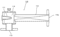
도 2는 본 발명의 제1 실시 형태에 따른 알칼리 수전해 장치에 이용하는 이젝터의 일 예의 상세를 나타내는 단면도이다.
도 3은 본 발명의 다른 실시 형태에 따른 알칼리 수전해 장치의 일부(불순물 제거 수단)를 나타내는 플로우도이다.1 is a flow chart showing an alkaline water electrolytic apparatus according to a first embodiment of the present invention.
2 is a cross-sectional view showing details of an example of an ejector used in the alkaline water electrolytic apparatus according to the first embodiment of the present invention.
3 is a flow chart showing a part (impurity removing means) of an alkaline water electrolytic device according to another embodiment of the present invention.
(발명을 실시하기 위한 형태)(Form for carrying out the invention)
〔제1 실시 형태〕[First Embodiment]
도 1은, 본 발명의 제1 실시 형태에 따른 전해 장치의 일 예를 나타내는 플로우도이다. 여기에서는 알칼리 수전해 장치를 예로 들어 설명한다. 단 본 발명은, 알칼리 수전해 외에, 비정제수의 전해, 식염 전해, 염화물 수용액, 브롬화물 수용액, 염산, 황산 수용액 전해 등, 전해에 의해 수소 가스가 발생하는 전해 장치에도 적용 가능하다.1 is a flow chart showing an example of an electrolytic device according to a first embodiment of the present invention. Here, an alkaline water electrolytic apparatus will be described as an example. However, the present invention is applicable to electrolytic devices in which hydrogen gas is generated by electrolysis, such as electrolysis of unrefined water, salt electrolysis, aqueous chloride solution, bromide aqueous solution, hydrochloric acid, and sulfuric acid aqueous solution, in addition to alkaline water electrolysis.
도 1에 있어서, 알칼리 수전해 장치는 전해조(1)를 갖는다. 2는 음극을 수용하는 음극실, 3은 양극을 수용하는 양극실, 4는 음극실(2)과 양극실(3)을 구획하는 격막이다. 격막(4)은, 양이온 교환막, 음이온 교환막, 고분자 다공층과 부직포로 이루어지는 복합막 등이다.In Fig. 1, the alkaline water electrolytic device has an
음극측에서의 전해액의 반송 경로로서, 음극측 전해액 순환 수단과, 음극 가스 분리 수단이 형성된다. 음극측 가스 분리 수단은, 음극측 전해액 배출 라인(9)과, 음극측 기액 분리 수단(10)과, 수소 가스 배출 라인(12)을 갖는다. 음극측 전해액 순환 수단은, 순환 탱크(5)와, 음극측 전해액 공급 라인(7)과, 순환 펌프(8)와, 음극측 전해액 회수 라인(11)을 갖는다.As a transport path of the electrolyte on the cathode side, a cathode-side electrolyte circulation means and a cathode gas separation means are formed. The cathode-side gas separation means includes a cathode-side
음극측 전해액 공급 라인(7)은, 음극실(2)과 순환 탱크(5)를 접속하고, 순환 펌프(8)에 의해, 순환 탱크(5) 내에 수납된 전해액(6)을 음극실(2)에 공급하는 배관이다. 음극측 전해액 배출 라인(9)은, 음극실(2)과 음극측 기액 분리 수단(10)을 접속하고, 음극실(2) 내의 전해액(음극측 전해액)과 수소 가스를 음극측 기액 분리 수단(10)에 반송하는 배관이다. 음극측 기액 분리 수단(10)은, 전해액으로부터 수소 가스를 분리한다. 음극측 전해액 회수 라인(11)은, 음극측 기액 분리 수단(10)과 순환 탱크(5)를 접속하고, 음극측 기액 분리 수단(10)에 의해 분리된 전해액을 순환 탱크(5)에 반송하는 배관이다. 수소 가스 배출 라인(12)은, 음극측 기액 분리 수단(10)과 후술하는 기체 압축 수단(101)을 접속하고, 음극측 기액 분리 수단(10)에 의해 분리된 수소 가스를 기체 압축 수단(101)에 반송하는 배관이다. 음극측 전해액 공급 라인(7)에 열 교환기(13)가 설치된다.The cathode-side electrolytic solution supply line 7 connects the cathode chamber 2 and the
양극측에서의 전해액의 반송 경로로서, 양극측 전해액 순환 수단과, 양극 가스 분리 수단이 형성된다. 양극 가스 분리 수단은, 양극측 전해액 배출 라인(16)과, 양극측 기액 분리 수단(17)과, 양극 가스 배출 라인(19)을 구비한다. 양극측 전해액 순환 수단은, 순환 탱크(5)와, 양극측 전해액 공급 라인(14)과, 순환 펌프(15)와, 양극측 전해액 회수 라인(18)을 갖는다.An anode side electrolyte circulation means and an anode gas separation means are formed as a transport path of the electrolyte on the anode side. The anode gas separating means includes an anode side electrolytic
양극측 전해액 공급 라인(14)은, 양극실(3)과 순환 탱크(5)를 접속하고, 순환 펌프(15)에 의해, 순환 탱크(5) 내에 수납된 전해액(6)을 양극실(3)에 공급하는 배관이다. 양극측 전해액 배출 라인(16)은, 양극실(3)과 양극측 기액 분리 수단(17)을 접속하고, 양극실(3) 내의 전해액(양극측 전해액)과 양극 가스(알칼리 수전해의 경우는 산소 가스)를 양극측 기액 분리 수단(17)에 반송하는 배관이다. 양극측 기액 분리 수단(17)은, 전해액으로부터 양극 가스를 분리한다. 양극측 전해액 회수 라인(18)은, 양극측 기액 분리 수단(17)과 순환 탱크(5)를 접속하고, 양극측 기액 분리 수단(17)에 의해 분리된 전해액을 순환 탱크(5)에 반송하는 배관이다. 양극 가스 배출 라인(19)은, 양극측 기액 분리 수단(17)에 접속하고, 양극측 기액 분리 수단(17)에 의해 분리된 양극 가스를 계 외로 배출하는 배관이다. 양극측 전해액 공급 라인(14)에 열 교환기(20)가 설치된다.The anode-side electrolyte
도 1의 예에서는, 전해액은 알칼리 수용액(예를 들면 알칼리 금속 수산화물의 수용액, 구체적으로 KOH 수용액 또는 NaOH 수용액)이다.In the example of Fig. 1, the electrolyte solution is an aqueous alkali solution (for example, an aqueous solution of an alkali metal hydroxide, specifically a KOH solution or a NaOH solution).
본 실시 형태의 전해 장치는, 전해액 보충 수단과 물 보충 수단을 구비한다. 전해액 보충 수단은, 고농도의 알칼리수(22)를 저류하는 알칼리수 탱크(21)와, 펌프(23)를 구비한다. 물 보충 수단은, 순수(25)를 저류하는 순수 탱크(24)와, 펌프(26)를 구비한다.The electrolytic device of the present embodiment includes an electrolytic solution replenishing means and water replenishing means. The electrolyte replenishment means includes an
알칼리 수전해 장치에서는, 도 1에 나타내는 바와 같이 양극측과 음극측에서 순환 탱크가 공통된다. 따라서, 음극측 전해액 순환 수단과 양극측 전해액 순환 수단에서는, 양극측 전해액과 음극측 전해액이 혼합된 전해액이, 음극실(2)과 순환 탱크(5)의 사이 및 양극실(3)과 순환 탱크(5)의 사이를 각각 순환한다.In the alkaline water electrolytic apparatus, as shown in Fig. 1, the circulation tank is common on the anode side and the cathode side. Therefore, in the cathode-side electrolyte circulating means and the anode-side electrolyte circulating means, the electrolyte in which the anode-side electrolyte and the cathode-side electrolyte are mixed is between the cathode chamber 2 and the
수소 가스 배출 라인(12)의 하류측에, 기체 압축 수단(101)이 형성된다. 기체 압축 수단(101)은, 음극측 이젝터(110)와, 음극측 혼합 유체 반송 파이프(102)와, 음극측 저류 탱크(103)와, 음극측 순환 펌프(104)와, 음극측 순환 파이프(105)와, 수소 가스 배출 파이프(106)를 구비한다.On the downstream side of the hydrogen
도 2는, 음극측 이젝터(110)의 일 예의 상세를 나타내는 단면도이다. 111은 노즐, 112는 디퓨저, 113은 흡입구, 114는 석션 챔버이다. 노즐(111)은, 순환 파이프(105)에 접속한다. 흡입구(113)는, 수소 가스 배출 라인(12)에 접속한다. 디퓨저(112)의 출구(112a)는, 음극측 혼합 유체 반송 파이프(102)에 접속한다.2 is a cross-sectional view showing details of an example of the cathode-
음극측 혼합 유체 반송 파이프(102)는 음극측 이젝터(110)와 음극측 저류 탱크(103)를 접속하고, 음극측 이젝터(110)로부터 배출된 혼합 유체를 음극측 저류 탱크(103)에 반송한다.The cathode-side mixed
음극측 저류 탱크(103)는, 순환용 액체(음극측 순환용 액체)를 내부에 수용한다. 이 순환용 액체는 물이고, 수소 가스에 포함되어 있던 불순물(후술)을 포함하고 있다. 음극측 저류 탱크(103)의 상부 공간에는, 음극측 이젝터(110)로부터 반송된 혼합 유체로부터 분리한 수소 가스가 저류된다. 음극측 저류 탱크(103)의 저부에 음극측 순환 파이프(105)가 접속된다. 음극측 저류 탱크(103)의 상부에 수소 가스 배출 파이프(106)가 접속된다. 수소 가스 배출 파이프(106)에 밸브(V1)(제1 밸브)가 설치된다.The cathode-
음극측 순환 파이프(105)에, 음극측 순환 펌프(104) 및 음극측 열 교환기(107)가 설치된다. 음극측 순환 펌프(104)에 의해, 음극측 저류 탱크(103) 내의 순환용 액체가 음극측 순환 파이프(105)를 경유하여 음극측 이젝터(110)에 순환된다.On the cathode
본 실시 형태의 전해 장치에서는, 음극측 순환 파이프(105)에 음극측 순환용 액체 취출 파이프(120)가 접속되어도 좋다. 음극측 순환용 액체 취출 파이프(120)에, 밸브(V2) 및 펌프(121)가 설치된다. 음극측 순환용 액체 취출 파이프(120)는, 순환용 액체의 일부를 계 외에 방출하도록 구성되어 있어도 좋고, 순환용 액체의 일부를 전해액에 순환하도록 구성되어 있어도 좋다. 순환용 액체를 전해액에 이용하기 위한 구성으로서는, 음극측에서의 전해액의 반송 경로 및 양극측에서의 전해액의 반송 경로 중 어느 장소에, 음극측 순환용 액체 취출 파이프(120)가 접속된다. 도 1의 예에서는, 음극측 순환용 액체 취출 파이프(120)가 순환 탱크(5)에 접속된다. 그 외, 음극측 순환용 액체 취출 파이프(120)는, 음극측 전해액 공급 라인(7), 음극측 전해액 배출 라인(9), 음극측 전해액 회수 라인(11), 양극측 전해액 공급 라인(14), 양극측 전해액 배출 라인(16), 양극측 전해액 회수 라인(18) 중 어느 개소에도 접속할 수 있다.In the electrolytic device of the present embodiment, the cathode
도 1의 전해 장치를 이용하여 전해 및 수소 가스의 압축을 행하는 공정을 이하에서 설명한다.The step of performing electrolysis and compression of hydrogen gas using the electrolytic apparatus in FIG. 1 will be described below.
전해 개시 전 및 초기에 있어서, 전해액 보충 수단은 펌프(23)에 의해 알칼리수(22)를 알칼리수 탱크(21)로부터 순환 탱크(5)에 공급한다. 물 보충 수단은, 펌프(26)에 의해 순수(25)를 순수 탱크(24)로부터 순환 탱크(5)에 공급한다. 알칼리수 및 순수가 순환 탱크(5) 내에서 혼합되고, 전해액(6)은 소정의 농도로 제어되어 있다. 순환 탱크(5) 내에는, 순수(25)와 함께, 새로운 전해용의 원료수를 첨가할 수도 있다.Before and at the beginning of electrolysis, the electrolyte replenishing means supplies the
전해액(6)은, 순환 펌프(8)에 의해 음극측 전해액 공급 라인(7)을 경유하여 전해조(1)의 음극실(2)에 공급된다. 전해액은 열 교환기(13)를 통과함으로써, 소정 온도로 냉각된다. 또한 전해액(6)은, 순환 펌프(15)에 의해 양극측 전해액 공급 라인(14)을 경유하여 전해조(1)의 양극실(3)에 공급된다. 전해액은 열 교환기(20)를 통과함으로써, 소정 온도로 냉각 또는 가열된다.The
음극실(2) 및 양극실(3) 내에서 전해액이 전해된다. 이에 따라, 음극실(2) 내에서 수소 가스가 생성되고, 양극실(3) 내에서 양극 가스(산소 가스)가 생성된다.Electrolyte is electrolyzed in the cathode chamber 2 and the
생성한 수소 가스는, 전해액과 함께, 음극측 전해액 배출 라인(9)을 통하여 음극측 기액 분리 장치(10)에 반송된다. 음극측 기액 분리 장치(10)에 의해, 수소 가스와 전해액이 기액 분리된다. 분리된 전해액은, 음극측 전해액 회수 라인(11)을 통하여 순환 탱크(5)에 순환된다. 분리된 수소 가스는, 음극 가스 배출 라인(12)을 통하여 기체 압축 수단(101)에 반송된다.The generated hydrogen gas is conveyed to the cathode-side gas-
생성한 산소 가스는, 전해액과 함께, 양극측 전해액 배출 라인(16)을 통하여 양극측 기액 분리 장치(17)에 반송된다. 양극측 기액 분리 장치(17)에 의해, 산소 가스와 전해액이 기액 분리된다. 분리된 전해액은, 양극측 전해액 회수 라인(18)을 통하여 순환 탱크(5)에 순환된다. 산소 가스는, 양극 가스 배출 라인(19)을 통하여 계 외로 배출된다.The generated oxygen gas is conveyed to the anode-side gas-
음극실(2) 및 양극실(3) 내의 알칼리 농도를 컨트롤하기 위해, 전해로 소실되는 물의 상당량이 순수 보충 수단으로부터 공급된다. 순수를 연속적으로 공급함으로써, 전해액의 농도 등의 전해 조건을 일정하게 유지하면서 전해를 계속한다. 또한, 순환 탱크의 용량에 의존하지만, 순수를 간헐적으로 공급하는 것도 가능하다.In order to control the alkali concentration in the cathode chamber 2 and the
기체 압축 수단(101)에 있어서, 음극측 순환 펌프(104)가 작동함으로써, 순환용 액체가 음극측 혼합 유체 반송 파이프(102) 및 음극측 순환 파이프(105)를 통하여 순환하고 있다. 음극측 이젝터(110) 내에서, 순환용 액체가 노즐(111)로부터 디퓨저(112)를 향하여 흐른다. 이에 따라, 수소 가스 배출 라인(12)으로부터 배출된 수소 가스가, 흡입구(113)로부터 석션 챔버(114)에 인입된다. 석션 챔버(114)에서 순환용 액체와 수소 가스가 격렬하게 혼합하고, 혼합 유체가 디퓨저(112)로부터 배출된다.In the gas compression means 101, when the cathode-
음극측 혼합 유체 반송 파이프(102)로부터 음극측 저류 탱크(103) 내에 혼합 유체가 분출된다. 음극측 이젝터(110) 내에서 순환용 액체(물)와 수소 가스가 격렬하게 혼합하고, 음극측 저류 탱크(103) 내에서 수소 가스와 순환용 액체가 분리된다. 이에 따라, 수소 가스 배출 라인(12)을 유통하는 수소 가스에 포함되어 있던 알칼리성 미스트(알칼리 수용액의 미스트)나 파티클 등의 불순물은 순환용 액체로 이행하여, 수소 가스와 불순물이 분리된다.The mixed fluid is ejected from the cathode-side mixed
또한, 도 2에 나타낸 음극측 이젝터(110)와 음극측 저류 탱크(103)의 사이에, 내부에 충전물을 충전한 충전탑(도시하지 않음)을 형성하면, 수소 가스와 음극측 순환 액체의 기액 접촉 면적이 커져, 수소 가스와 음극측 순환 액체가 충전탑을 통과할 때에 양자의 충돌도 격렬해지기 때문에, 수소 가스로부터 불순물이 제거되는 비율도 커진다. 당해 충전물로서는, 폴리프로필렌 수지, 폴리에틸렌 수지, 불소 수지 등을 각종 사이즈로 성형한 플라스틱 충전물, 금속 제선 구조(metal wire structure) 충전물 등을 사용할 수 있다. 플라스틱 충전물의 일 예로서는, 텔러렛(텔러렛(Tellerette)은, 츠키시마칸쿄 엔지니어링 가부시키가이샤의 등록상표)이 있고, 금속 제선 구조 충전물의 일 예로서, 라시히 링 슈퍼 링크(라시히 링 슈퍼 링크(Raschig ring super link)는, 라시히사(독일)의 등록상표)가 있다.In addition, when a filling tower (not shown) filled with a filling material is formed between the cathode-
당해 충전탑은, 음극측 이젝터(110)의 외부에 형성하는 것이 바람직하지만, 음극측 이젝터(110)의 디퓨저(112)의 출구(112a)의 내부에 형성해도 좋고, 혹은, 충전탑 대신에, 그의 내부에 충전되어 있는 충전물만을 디퓨저(112)의 출구(112a)의 내부에 형성해도 좋다.The charging tower is preferably formed outside the cathode-
음극측 저류 탱크(103)에 저류된, 불순물을 포함하는 순환용 액체는, 음극측 순환 펌프(104)에 의해 음극측 순환 파이프(105)를 통하여 음극측 이젝터(110)에 순환된다. 이 도중에, 음극측 열 교환기(107)에 의해 순환용 액체가 냉각 또는 가열된다.The liquid for circulation, which contains impurities, stored in the cathode-
음극측 저류 탱크(103)로부터 음극측 이젝터(110)로 순환하는 음극측 순환용 액체의 순환 속도(유속)와, 밸브(V1)의 개폐를 제어함으로써, 음극측 저류 탱크(103) 내에 저류되는 수소 가스가 승압된다. 예를 들면, 전해 장치의 운전을 개시할 때에는, 밸브(V1)를 폐(close)로 하고, 기체 압축 수단(101) 내를 폐루프로 한다. 이 상태에서 음극측 순환용 액체의 유속을 올리면, 수소 가스는 가압 상태에서 음극측 저류 탱크(103) 내에 저류된다. 수소 가스가 소정의 압력까지 상승한 시점에서, 밸브(V1)를 개방하고, 정상 운전으로 한다.By controlling the circulation speed (flow rate) of the cathode-side circulating liquid circulating from the cathode-
음극측 순환용 액체의 유속을 올릴수록, 음극측 이젝터(110)의 흡인력이 증가한다. 이 결과, 기체 압축 수단(101)에 유입되는 수소 가스량이 증가하고, 수소 가스의 압력이 상승한다. 본 발명에서는, 수소 가스를 최대로 1㎫(10bar)까지 가압한다. 예를 들면, 음극측 순환용 액체의 순환 속도를 150㎥/h로 올림으로써, 음극측 저류 탱크(103) 내에 저류되는 수소 가스는, 0.6㎫(6bar)∼1㎫(10bar)로 가압된다.As the flow rate of the cathode-side circulation liquid is increased, the suction force of the cathode-
이젝터의 기능은, 일반적으로 가스 그리고 액을 속도가 빠른 유체를 흐르게 함으로써, 그 흐름에 수반하여 가스 또는 액체를 흡인하는 것이다. 본 발명에서는, 음극측 이젝터(110)에 음극측 순환용 액체를 흐르게 함으로써, 수소 가스 배출 라인(12)을 통하여 수소 가스를 음극측 이젝터(110) 내에 흡인한다. 음극측 이젝터(110)에서는, 좁은 관 내에서 수소 가스와 순환용 액체가 격렬하게 부딪친다.The function of the ejector is to draw a gas or a liquid along with the flow, generally by flowing a gas and a liquid at a high velocity. In the present invention, by flowing the cathode-side circulating liquid to the cathode-
이 현상 중, 고압을 달성하기 위해, 추가로 수소 가스 내의 불순물인 알칼리성 미스트는, 순환용 액체인 물에 부딪쳐, 순환용 액체인 물에 용해되는 확률이 증대한다.Among these phenomena, in order to achieve high pressure, the alkali mist, which is an impurity in the hydrogen gas, further hits water, which is a circulating liquid, and increases the probability of being dissolved in water, which is a circulating liquid.
본 발명에 있어서는, 음극측 저류 탱크(103)로부터 음극측 이젝터(110)로의 음극측 순환용 액체의 순환 속도와, 밸브(V1)의 개폐를 제어함으로써, 수소 가스의 압력을 제어할 수 있다. 본 발명의 기체 압축 수단(101)에 의해 수소 가스를 최대로 1㎫(10bar)까지 가압하기 때문에, 고압 설비를 필요로 하지 않는다. 이 때문에, 설비를 간략화할 수 있음과 함께, 메인터넌스가 용이해진다.In the present invention, the pressure of the hydrogen gas can be controlled by controlling the circulation speed of the cathode-side circulating liquid from the cathode-
본 발명의 기체 압축 수단(101)에서는 대형의 압축기를 이용할 필요가 없기 때문에, 설치 면적을 대폭으로 삭감할 수 있다. 또한, 압축기의 냉각 보조 기계 등의 설치가 불필요하다. 본 발명에 의한 음극측 이젝터(110)에는 구동부가 없기 때문에, 진동, 소음, 장기 운전 시의 기계적 손상이 없고, 장기에 걸쳐 안정적으로 사용할 수 있다. 이 결과, 장치의 메인터넌스비가 대폭으로 저감된다.Since the gas compression means 101 of the present invention does not need to use a large compressor, the installation area can be significantly reduced. In addition, it is not necessary to install a compressor, such as a cooling auxiliary machine. Since the cathode-
이에 대하여, 종래부터 실시되고 있는 수 세정탑에 의한 세정에 있어서는, 예를 들면 100N㎥/h의 수소 발생량에 대하여 세정수의 공급량은 5㎥/h이다. 세정수와 처리해야 할 발생 수소량의 비로부터 고려해도, 수 세정탑에 의한 세정에서는 불순물 제거 효율은 낮다. 또한, 수 세정탑에 의한 세정에서는 수소 가스의 가압은 행해지지 않는다.On the other hand, in the washing with a water washing tower which has been conventionally performed, the supply amount of washing water is 5
불순물이 제거되고 승압된 수소 가스는, 수소 가스 배출 파이프(106)를 경유하여 전해 장치의 계 외로 배출된다. 배출된 수소 가스는, 예를 들면 탱크에 저류된 후, 다른 용도(연료 전지 등)로 사용된다. 보다 고압의 수소 가스를 제조하는 경우, 본 발명의 전해 장치를 이용하여 압축된 수소 가스를 이용하면, 대기압으로부터 승압하는 경우에 비해 에너지를 삭감할 수 있기 때문에 유리하다.The hydrogen gas from which impurities have been removed and boosted is discharged out of the system of the electrolytic device via the hydrogen
기체 압축 수단(101) 내에서 순환용 액체가 순환됨으로써, 순환용 액체 중에 알칼리성 미스트가 용해되어, 순환용 액체의 pH가 상승한다. 기체 압축 수단(101)의 계 내 중에 순환용 액체의 pH를 계측하는 수단(도 1에서는 도시하지 않음)을 설치하고, 밸브(V2)와 연동시킨다. pH 계측 수단은 예를 들면 음극측 저류 탱크(103)나 순환 파이프(105)에 설치된다. 순환용 액체의 pH가 소정값에 도달한 경우에, 밸브(V2)가 개방된다. 밸브(V2)의 개방에 의해, 순환용 액체의 일부가 음극측 순환용 액체 취출 파이프(120)를 유통한다.As the circulation liquid is circulated in the gas compression means 101, the alkaline mist is dissolved in the circulation liquid, and the pH of the circulation liquid is raised. In the system of the gas compression means 101, a means (not shown in FIG. 1) for measuring the pH of the circulating liquid is provided and interlocked with the valve V2. The pH measuring means is installed in, for example, the cathode-
음극측 순환용 액체는 순환용 액체 취출 파이프(120)를 경유하여 계 외로 배출되어도 좋다. 혹은, 음극측 순환용 액체는, 음극측 순환용 액체 취출 파이프(120)를 경유하여 음극측에서의 전해액의 반송 경로 및 양극측에서의 전해액의 반송 경로 중 어느 장소에 있어서 전해액에 첨가하여, 전해액으로서 이용할 수도 있다. 예를 들면 도 1에 나타내는 알칼리 수전해 장치에서는, 기체 압축 수단(101)으로부터 배출된 음극측 순환용 액체는, 음극측 순환용 액체 취출 파이프(120)를 경유하여 순환 탱크(5)에 공급되어 전해액과 혼합한다.The cathode-side circulation liquid may be discharged out of the system via the circulation
〔제2 실시 형태〕[Second Embodiment]
도 3은, 본 발명의 제2 실시 형태에 따른 전해 장치의 일 예이고, 전해 장치의 일부인 불순물 제거 수단을 나타낸 플로우도이다. 본 실시 형태에 있어서도, 알칼리 수전해 장치를 예로 들어 설명한다.3 is an example of an electrolytic device according to a second embodiment of the present invention, and is a flow chart showing means for removing impurities that are part of the electrolytic device. Also in the present embodiment, an alkaline water electrolytic device will be described as an example.
제2 실시 형태의 전해 장치는, 도 1에 나타낸 제1 실시 형태에 따른 전해 장치의 양극 가스 배출 라인(19)의 하류측에, 추가로 불순물 제거 수단(201)이 형성되어 있는 예이다. 불순물 제거 수단(201)의 구성은, 기본적으로 기체 압축 수단(101)과 동일하다. 즉, 불순물 제거 수단(201)은, 양극측 이젝터(210)와, 양극측 혼합 기체 반송 파이프(202)와, 양극측 저류 탱크(203)와, 양극측 순환 펌프(204)와, 양극측 순환 파이프(205)와, 양극 가스 배출 파이프(206)를 구비한다. 양극 가스 배출 파이프(206)에 밸브(V3)(제2 밸브)가 설치된다.The electrolytic device of the second embodiment is an example in which the impurity removing means 201 is further formed on the downstream side of the anode
양극측 이젝터(210)는 제1 실시 형태에서 설명한 음극측 이젝터(101)와 동일한 구성이다. 양극측 이젝터(210)의 노즐(211)은 양극측 순환 파이프(205)에 접속한다. 양극측 이젝터(210)의 흡입구(213)는 양극 가스 배출 라인(19)에 접속한다. 양극측 이젝터(210)의 디퓨저 출구는 양극측 혼합 유체 반송 파이프(202)를 통하여 양극측 저류 탱크(203)에 접속한다.The anode-
또한, 양극측 이젝터(210)에 있어서도, 양극측 이젝터(210)와 양극측 저류 탱크(203)의 사이에, 내부에 충전물을 충전한 충전탑(도시하지 않음)을 형성하면, 양극 가스와 양극측 순환 액체의 기액 접촉 면적이 커져, 양극 가스와 양극측 순환 액체가 충전탑을 통과할 때에 양자의 충돌도 격렬해지기 때문에, 양극 가스로부터 불순물이 제거되는 비율도 커진다.In addition, in the anode-
당해 충전탑은, 양극측 이젝터(210)의 외부에 형성하는 것이 바람직하지만, 양극측 이젝터(210)의 디퓨저의 출구의 내부에 형성해도 좋고, 혹은, 충전탑 대신에, 그의 내부에 충전되어 있는 충전물만을 디퓨저의 출구의 내부에 형성해도 좋다.The charging tower is preferably formed outside the anode-
양극측 순환 파이프(205)에, 양극측 순환 펌프(204) 및 양극측 열 교환기(207)가 설치된다. 양극측 순환 펌프(204)에 의해, 양극측 저류 탱크(203) 내의 순환용 액체(물)가 양극측 순환 파이프(205) 및 노즐(211)을 경유하여 양극측 이젝터(210)에 순환된다.The anode
양극측에 있어서도, 양극측 순환 파이프(205)에 양극측 순환용 액체 취출 파이프(220)가 접속되어도 좋다. 양극측 순환용 액체 취출 파이프(220)는, 양극측 순환용 액체 취출 파이프(220)에 의해 순환용 액체를 계 외에 방출하도록 구성되어 있어도 좋다. 혹은, 음극측에서의 전해액의 반송 경로 및 양극측에서의 전해액의 반송 경로 중 어느 장소에 양극측 순환용 액체 취출 파이프(220)가 접속되어, 순환용 액체의 일부를 전해액에 첨가하도록 구성되어 있어도 좋다. 구체적으로, 양극측 순환용 액체 취출 파이프(220)는, 순환 탱크(5), 음극측 전해액 공급 라인(7), 음극측 전해액 배출 라인(9), 음극측 전해액 회수 라인(11), 양극측 전해액 공급 라인(14), 양극측 전해액 배출 라인(16), 양극측 전해액 회수 라인(18) 중 어느 개소에 접속할 수 있다. 양극측 순환용 액체 취출 파이프(220)에, 제4 밸브(V4) 및 펌프(221)가 설치된다.On the anode side, the anode
도 3에 나타내는 불순물 제거 수단으로 불순물의 제거 및 양극 가스의 압축을 행하는 공정을 이하에 설명한다.The process of removing impurities and compressing the anode gas by means of removing impurities shown in Fig. 3 will be described below.
불순물 제거 수단(201)에 있어서, 양극측 순환 펌프(204)가 작동함으로써, 순환용 액체가 양극측 혼합 유체 반송 파이프(202) 및 양극측 순환 파이프(205)를 통하여 순환하고 있다. 양극측 이젝터(210) 내에서, 순환용 액체가 노즐(211)로부터 디퓨저를 향하여 흐름으로써, 양극 가스 배출 라인(19)을 유통하는 양극 가스(산소 가스)가 양극측 이젝터(210) 내로 인입된다. 양극측 이젝터(210) 내에서 순환용 액체와 양극 가스가 격렬하게 혼합하고, 혼합 유체가 양극측 이젝터(210)로부터 배출된다.In the impurity removal means 201, the anode-
양극측 혼합 유체 반송 파이프(202)로부터 양극측 저류 탱크(203) 내에 혼합 유체가 분출된다. 양극측 이젝터(210) 내에서 순환용 액체(물)와 양극 가스가 격렬하게 혼합하고, 양극측 저류 탱크(203) 내에서 양극 가스와 순환용 액체가 분리됨으로써, 알칼리성 미스트나 파티클 등의 불순물은 순환용 액체로 이행하여, 양극 가스와 불순물이 분리된다.The mixed fluid is ejected from the anode-side mixed
양극측 저류 탱크(203)에 저류된 순환용 액체는, 양극측 순환 펌프(204)에 의해 양극측 순환 파이프(205)를 통하여 양극측 이젝터(210)에 순환된다.The circulation liquid stored in the anode-
승압하지 않고 양극 가스를 대기 방출하는 경우는, 밸브(V3)를 전개로 한다.When the anode gas is released into the atmosphere without boosting, the valve V3 is deployed.
양극 가스를 승압하는 경우에는, 양극측 저류 탱크(203)로부터 양극측 이젝터(210)로의 양극측 순환용 액체의 순환 속도(유속)를 제어함으로써, 양극측 저류 탱크(203) 내에 저류되는 양극 가스가 승압된다. 예를 들면, 운전 개시 시에 밸브(V3)를 폐로 하고 불순물 제거 수단(201) 내를 폐루프로 한다. 이 상태에서 양극측 순환용 액체의 유속을 올리면, 양극 가스는 가압 상태에서 양극측 저류 탱크(203) 내에 저류된다. 양극 가스가 소정의 압력까지 상승한 시점에서, 밸브(V3)를 개방하고, 정상 운전으로 한다.When boosting the anode gas, by controlling the circulation speed (flow rate) of the anode-side circulating liquid from the anode-
양극측 순환용 액체의 유속을 올릴수록, 양극 가스의 압력이 상승한다. 예를 들면 양극측 순환용 액체의 순환 속도를 150㎥/h 이하로 함으로써, 전해에 의해 생성하는 양극 가스는, 0.6㎫(6bar) 이하의 저압으로 할 수 있다. 한편, 양극측 순환용 액체의 순환 속도를 150㎥/h 이상으로 함으로써, 전해에 의해 생성하는 양극 가스를, 0.6㎫(6bar)∼1㎫(10bar)로 가압할 수 있다. 즉, 본 실시 형태의 불순물 제거 수단(201)은, 기체 압축 수단(101)과 동일한 효과를 가져올 수 있다.As the flow rate of the anode-side circulation liquid increases, the pressure of the anode gas increases. For example, by setting the circulation speed of the anode-side circulating liquid to 150
불순물 제거 수단(201) 내에서 순환용 액체 중에 알칼리성 미스트가 용해함으로써, 순환용 액체의 pH가 상승한다. 불순물 제거 수단(201)의 계 내 중에 순환용 액체의 pH를 계측하는 수단(도 3에서는 도시하지 않음)을 설치하고, 밸브(V4)와 연동시킨다. pH 계측 수단은, 예를 들면 양극측 저류 탱크(203)나 양극측 순환 파이프(205)에 설치된다. 순환용 액체의 pH가 소정값에 도달한 경우에 밸브(V4)가 개방되고, 순환용 액체의 일부가 양극측 순환용 액체 취출 파이프(220)를 경유하여 불순물 제거 수단(201)으로부터 배출된다. 배출된 순환용 액체는 양극측 순환용 액체 취출 파이프(220)를 경유하여 계 외로 배출되어도 좋다. 순환용 액체는, 순환용 액체 취출 파이프(220)를 경유하여 음극측에서의 전해액의 반송 경로 및 양극측에서의 전해액의 반송 경로 중 어느 장소에 있어서 전해액에 첨가되어, 전해액으로서 이용되어도 좋다. 예를 들면 알칼리 수전해 장치에서는, 양극측 순환용 액체 취출 파이프(220)가 도 1에 나타내는 순환 탱크(5)에 접속하는 구성으로서, 양극측 순환용 액체가 순환 탱크(5)에 공급되어 전해액과 혼합되어도 좋다.When the alkaline mist is dissolved in the circulating liquid in the impurity removing means 201, the pH of the circulating liquid increases. In the system of the impurity removing means 201, a means (not shown in FIG. 3) for measuring the pH of the circulating liquid is provided and interlocked with the valve V4. The pH measurement means is provided in, for example, the anode-
이상의 실시 태양(態樣)에 있어서는, 양극측 전해액 및 음극측 전해액은, 순환 탱크(5)를 통하여 순환하고 있는 예를 나타냈지만, 이들 양극측 전해액 및 음극측 전해액은, 순환하지 않고, 양극측 전해액 회수 라인(18) 및 음극측 전해액 회수 라인(11)으로부터 장치 외로 배출되어도 좋다.In the above-described embodiment, an example in which the anode side electrolyte solution and the cathode side electrolyte solution are circulated through the
즉, 도 1 및 도 3은, 알칼리 수전해 장치의 일 예를 나타낸 것이고, 음극측 전해액 및 양극측 전해액이 공통의 전해액으로서, 음극실(2) 및 양극실(3)에 순환하는 예에 대해서 설명했다. 그러나 본 발명은, 음극실(2) 및 양극실(3)로 전해액의 순환을 행하지 않는 경우에도 적용할 수 있다.That is, FIGS. 1 and 3 show an example of an alkaline water electrolytic device, and an example in which the cathode side electrolyte and the anode side electrolyte are circulated in the cathode chamber 2 and the
또한, 음극측 전해액 순환 수단 및 양극측 전해액 순환 수단 중 어느 한쪽만이 설치되는 경우도 있다. 예를 들면, 음극측은 음극측 전해액 순환 수단을 형성하여 음극실(2)로 전해액이 순환되는 구성으로 하는 한편으로, 양극측은 양극측 전해액 회수 라인으로부터 전해액을 양극실(3)로 순환하지 않고 장치 외로 배출하는 구성으로 할 수도 있다.In addition, only one of the cathode side electrolyte circulation means and the anode side electrolyte circulation means may be provided. For example, the cathode side is configured to circulate the electrolyte into the cathode chamber 2 by forming a cathode-side electrolyte circulation means, while the anode side is a device without circulating the electrolyte from the anode-side electrolyte recovery line to the
추가로 본 발명은, 알칼리 수전해 이외에, 식염 전해, 황산 전해, 염산 전해, 브롬산 전해 등의 수용액 전해에도 적용할 수 있다. 이들 전해에 있어서는, 도 1에 나타나는 순환 탱크(5) 대신에, 음극측 순환 탱크 및 양극측 순환 탱크를 설치한다. 이 경우, 음극측에서 음극측 전해액을 음극측 순환 탱크와 음극실의 사이에 순환시키고, 양극측에서 양극측 전해액을 양극측 순환 탱크와 양극실의 사이에서 순환시켜도 좋다.In addition, the present invention can be applied to aqueous electrolysis such as salt electrolysis, sulfuric acid electrolysis, hydrochloric acid electrolysis, and bromic acid electrolysis, in addition to alkaline water electrolysis. In these electrolysis, a cathode side circulation tank and an anode side circulation tank are provided instead of the
또한, 알칼리 수전해와 마찬가지로, 음극측 전해액 순환 수단 및 양극측 전해액 순환 수단 중 어느 한쪽만이 설치되는 경우도 있다. 예를 들면, 음극측은 음극측 전해액 순환 수단을 형성하여 전해액이 순환되는 구성으로 하는 한편으로, 양극측은 양극측 전해액 회수 라인으로부터 장치 외로 배출하는 구성으로 할 수도 있다.In addition, as in the case of alkaline water electrolysis, only one of the cathode side electrolyte circulation means and the anode side electrolyte circulation means may be provided. For example, the cathode side may have a configuration in which the electrolyte is circulated by forming a cathode-side electrolyte circulation means, while the anode side may be configured to discharge from the anode-side electrolyte recovery line out of the apparatus.
알칼리 수전해에 있어서는, 음극측 전해액 및 양극측 전해액은, 모두 알칼리 수용액이기 때문에, 수소 가스 및 양극 가스 중의 불순물은, 알칼리성 미스트를 포함한다. 그 외의 전해에 있어서는, 양극 가스 중의 불순물은, 산성 미스트를 포함한다. 특히, 식염 전해에 있어서는, 양극측 전해액은, 염화물 수용액이기 때문에, 산성 미스트 중에 고형물인 NaCl이 혼입되는 경우가 있다. 이러한 알칼리 수전해 이외의 전해라도, 상기에서 설명한 알칼리 수전해와 마찬가지로, 가스 중의 불순물을 제거할 수 있음과 함께, 가스를 승압할 수 있다.In the alkaline water electrolysis, since both the cathode-side electrolyte solution and the anode-side electrolyte solution are aqueous alkali solutions, impurities in the hydrogen gas and the anode gas contain an alkaline mist. In other electrolysis, impurities in the anode gas contain an acidic mist. Particularly, in salt electrolysis, since the anode-side electrolytic solution is an aqueous chloride solution, NaCl, which is a solid substance, may be mixed in the acidic mist. Even in the electrolysis other than the alkaline water electrolysis, the impurities in the gas can be removed and the gas can be boosted, as in the alkaline water electrolysis described above.
1 : 전해조
2 : 음극실
3 : 양극실
4 : 격막
5 : 순환 탱크
6 : 전해액
7 : 음극측 전해액 공급 라인
8 : 순환 펌프
9 : 음극측 전해액 배출 라인
10 : 음극측 기액 분리 수단
11 : 음극측 전해액 회수 라인
12 : 수소 가스 배출 라인
13 : 열 교환기
14 : 양극측 전해액 공급 라인
15 : 순환 펌프
16 : 양극측 전해액 배출 라인
17 : 양극측 기액 분리 수단
18 : 양극측 전해액 회수 라인
19 : 양극 가스 배출 라인
20 : 열 교환기
21 : 알칼리수 탱크
22 : 알칼리수
23 : 펌프
24 : 순수 탱크
25 : 순수
26 : 펌프
101 : 기체 압축 수단
102 : 음극측 혼합 유체 반송 파이프
103 : 음극측 저류 탱크
104 : 음극측 순환 펌프
105 : 음극측 순환 파이프
106 : 수소 가스 배출 파이프
107 : 음극측 열 교환기
110 : 음극측 이젝터
111 : 노즐
112 : 디퓨저
112a : 디퓨저(112)의 출구
113 : 흡입구
114 : 석션 챔버
120 : 음극측 순환용 액체 취출 파이프
121 : 음극측 펌프
201 : 불순물 제거 수단
202 : 양극측 혼합 유체 반송 파이프
203 : 양극측 저류 탱크
204 : 양극측 순환 펌프
205 : 양극측 순환 파이프
206 : 양극 가스 배출 파이프
207 : 양극측 열 교환기
210 : 양극측 이젝터
211 : 노즐
213 : 흡입구
220 : 양극측 순환용 액체 취출 파이프
221 : 양극측 펌프1: Electrolyzer
2: Cathode chamber
3: anode chamber
4: diaphragm
5: circulation tank
6: Electrolyte
7: Cathode side electrolyte solution supply line
8: Circulation pump
9: Cathode side electrolyte discharge line
10: cathode-side gas-liquid separation means
11: Cathode side electrolytic solution recovery line
12: hydrogen gas discharge line
13: heat exchanger
14: anode side electrolyte supply line
15: circulation pump
16: anode side electrolyte discharge line
17: anode-side gas-liquid separation means
18: anode side electrolytic solution recovery line
19: anode gas discharge line
20: heat exchanger
21: alkaline water tank
22: alkaline water
23: Pump
24: pure tank
25: pure
26: pump
101: gas compression means
102: cathode side mixed fluid conveying pipe
103: cathode side storage tank
104: cathode side circulation pump
105: cathode side circulation pipe
106: hydrogen gas discharge pipe
107: cathode side heat exchanger
110: cathode side ejector
111: nozzle
112: diffuser
112a: exit of
113: inlet
114: suction chamber
120: cathode side circulation liquid extraction pipe
121: cathode side pump
201: means for removing impurities
202: anode side mixed fluid conveying pipe
203: anode side storage tank
204: anode side circulation pump
205: anode side circulation pipe
206: anode gas discharge pipe
207: anode side heat exchanger
210: anode side ejector
211: nozzle
213: intake
220: liquid extraction pipe for anode side circulation
221: anode side pump
Claims (9)
상기 음극실에 접속하고, 수소 가스를 포함하는 음극측 전해액을 상기 음극실로부터 배출하는 음극측 전해액 배출 라인과,
상기 음극측 전해액 배출 라인에 접속하고, 상기 음극측 전해액으로부터 상기 수소 가스를 분리하는 음극측 기액 분리 수단과,
상기 음극측 기액 분리 수단에 접속하고, 상기 음극측 기액 분리 수단에 의해 분리된 상기 수소 가스를 상기 음극측 기액 분리 수단으로부터 배출하는 수소 가스 배출 라인과,
상기 수소 가스 배출 라인에 접속하는 기체 압축 수단
을 구비하고,
상기 기체 압축 수단은,
상기 수소 가스 배출 라인에 접속하는 음극측 이젝터와,
상기 수소 가스와 상기 기체 압축 수단 내를 유통하는 음극측 순환용 액체를 저류하는 음극측 저류 탱크와,
상기 음극측 이젝터와 상기 음극측 저류 탱크를 연결하고, 상기 음극측 이젝터로부터 상기 음극측 저류 탱크에 상기 음극측 순환용 액체와 상기 수소 가스의 혼합 유체를 반송하는 음극측 혼합 유체 반송 파이프와,
상기 음극측 저류 탱크와 상기 음극측 이젝터를 연결하고, 상기 음극측 저류 탱크로부터 상기 음극측 이젝터에 상기 음극측 순환용 액체를 반송하는 음극측 순환 파이프와,
상기 음극측 순환 파이프에 설치되는 음극측 순환 펌프와,
상기 음극측 저류 탱크에 접속하고, 상기 음극측 저류 탱크로부터 상기 수소 가스를 배출하는 수소 가스 배출 파이프와,
상기 수소 가스 배출 파이프에 형성되는 제1 밸브
를 갖고,
상기 음극측 순환 펌프, 상기 음극측 혼합 유체 반송 파이프 및 상기 음극측 순환 파이프에 의해, 상기 음극측 순환용 액체를 상기 음극측 저류 탱크로부터 상기 음극측 이젝터에 순환시킴으로써 상기 수소 가스를 상기 수소 가스 배출 라인으로부터 상기 음극측 이젝터 내에 유입시키고, 상기 음극측 이젝터 내에서 상기 수소 가스와 상기 음극측 순환용 액체를 혼합시키고, 상기 수소 가스 중의 불순물을 상기 음극측 순환용 액체로 이행시켜 상기 수소 가스로부터 상기 불순물을 제거함과 함께,
상기 음극측 저류 탱크로부터 상기 음극측 이젝터로 순환시키는 상기 음극측 순환용 액체의 유속과, 상기 제1 밸브의 개폐를 제어함으로써, 상기 음극측 저류 탱크 내에 저류되는 상기 수소 가스의 압력을 승압하는 것을 특징으로 하는 전해 장치.An electrolytic cell having an anode chamber accommodating the anode, a cathode chamber accommodating the cathode, and a diaphragm partitioning the anode chamber and the cathode chamber,
A cathode-side electrolyte discharge line that is connected to the cathode chamber and discharges a cathode-side electrolyte containing hydrogen gas from the cathode chamber;
A cathode-side gas-liquid separation means for connecting to the cathode-side electrolyte discharge line and separating the hydrogen gas from the cathode-side electrolyte;
A hydrogen gas discharge line connected to the cathode-side gas-liquid separation means and discharging the hydrogen gas separated by the cathode-side gas-liquid separation means from the cathode-side gas-liquid separation means;
Gas compression means connected to the hydrogen gas discharge line
Equipped with,
The gas compression means,
A cathode-side ejector connected to the hydrogen gas discharge line,
A cathode-side storage tank for storing the hydrogen gas and a cathode-side circulation liquid circulating in the gas compression means;
A cathode-side mixed fluid transfer pipe connecting the cathode-side ejector and the cathode-side storage tank, and conveying a mixed fluid of the cathode-side circulation liquid and the hydrogen gas from the cathode-side ejector to the cathode-side storage tank;
A cathode-side circulation pipe connecting the cathode-side storage tank and the cathode-side ejector, and conveying the cathode-side circulation liquid from the cathode-side storage tank to the cathode-side ejector;
A cathode-side circulation pump installed in the cathode-side circulation pipe,
A hydrogen gas discharge pipe connected to the cathode-side storage tank and discharging the hydrogen gas from the cathode-side storage tank;
A first valve formed on the hydrogen gas discharge pipe
Have
The hydrogen gas is discharged from the hydrogen gas by circulating the cathode-side circulation liquid from the cathode-side storage tank to the cathode-side ejector by the cathode-side circulation pump, the cathode-side mixed fluid transfer pipe, and the cathode-side circulation pipe. Flowing from the line into the cathode-side ejector, mixing the hydrogen gas and the cathode-side circulating liquid in the cathode-side ejector, and transferring impurities in the hydrogen gas to the cathode-side circulating liquid from the hydrogen gas; In addition to removing impurities,
Boosting the pressure of the hydrogen gas stored in the cathode-side storage tank by controlling the flow rate of the cathode-side circulation liquid circulating from the cathode-side storage tank to the cathode-side ejector and opening and closing of the first valve. Electrolytic device characterized by.
상기 양극실에 접속하고, 양극 가스를 포함하는 양극측 전해액을 상기 양극실로부터 배출하는 양극측 전해액 배출 라인과,
상기 양극측 전해액 배출 라인에 접속하고, 상기 양극측 전해액으로부터 양극 가스를 분리하는 양극측 기액 분리 수단과,
상기 양극측 기액 분리 수단에 접속하고, 상기 양극측 기액 분리 수단에 의해 분리된 상기 양극 가스를 상기 양극측 기액 분리 수단으로부터 배출하는 양극 가스 배출 라인과,
상기 양극 가스 배출 라인에 접속하는 불순물 제거 수단
을 구비하고,
상기 불순물 제거 수단은,
상기 양극 가스 배출 라인에 접속하는 양극측 이젝터와,
상기 양극 가스와 상기 불순물 제거 수단 내를 유통하는 양극측 순환용 액체를 저류하는 양극측 저류 탱크와,
상기 양극측 이젝터와 상기 양극측 저류 탱크를 연결하고, 상기 양극측 이젝터로부터 상기 양극측 저류 탱크에 상기 양극측 순환용 액체와 상기 양극 가스의 혼합 유체를 반송하는 양극측 혼합 유체 반송 파이프와,
상기 양극측 저류 탱크와 상기 양극측 이젝터를 연결하고, 상기 양극측 저류 탱크로부터 상기 양극측 이젝터에 상기 양극측 순환용 액체를 반송하는 양극측 순환 파이프와,
상기 양극측 순환 파이프에 설치되는 양극측 순환 펌프를 갖고,
상기 양극측 순환 펌프, 상기 양극측 혼합 유체 반송 파이프 및 상기 양극측 순환 파이프에 의해, 상기 양극측 순환용 액체를 상기 양극측 저류 탱크로부터 상기 양극측 이젝터에 순환시킴으로써 상기 양극 가스를 상기 양극 가스 배출 라인으로부터 상기 양극측 이젝터 내에 유입시키고, 상기 양극측 이젝터 내에서 상기 양극 가스와 상기 양극측 순환용 액체를 혼합시키고, 상기 양극 가스 중의 불순물을 상기 양극측 순환용 액체로 이행시켜 상기 양극 가스 중의 상기 불순물을 제거하는 전해 장치.According to claim 1,
An anode-side electrolyte discharge line that is connected to the anode chamber and discharges the anode-side electrolyte containing the anode gas from the anode chamber;
An anode-side gas-liquid separation means for connecting to the anode-side electrolyte discharge line and separating the anode gas from the anode-side electrolyte;
An anode gas discharge line connected to the anode-side gas-liquid separating means and discharging the anode gas separated by the anode-side gas-liquid separating means from the anode-side gas-liquid separating means;
Impurity removing means connected to the anode gas discharge line
Equipped with,
The impurity removing means,
An anode side ejector connected to the anode gas discharge line,
An anode-side storage tank for storing the anode gas and an anode-side circulation liquid circulating in the impurity removing means,
An anode-side mixed fluid transport pipe connecting the anode-side ejector and the anode-side storage tank, and conveying a mixed fluid of the anode-side circulation liquid and the anode gas from the anode-side ejector to the anode-side storage tank;
An anode-side circulation pipe connecting the anode-side storage tank and the anode-side ejector, and conveying the anode-side circulation liquid from the anode-side storage tank to the anode-side ejector;
It has an anode-side circulation pump installed in the anode-side circulation pipe,
The anode gas is discharged from the anode gas by circulating the anode-side circulation liquid from the anode-side storage tank to the anode-side ejector by the anode-side circulation pump, the anode-side mixed fluid conveying pipe, and the anode-side circulation pipe. Flowing from the line into the anode-side ejector, mixing the anode gas and the anode-side circulating liquid in the anode-side ejector, and transferring impurities in the anode gas to the anode-side circulating liquid so that the Electrolytic device to remove impurities.
상기 불순물 제거 수단이,
상기 양극측 저류 탱크에 접속하고, 상기 양극측 저류 탱크로부터 상기 양극 가스를 배출하는 양극 가스 배출 파이프와,
상기 양극 가스 배출 파이프에 형성되는 제2 밸브
를 추가로 구비하고,
상기 양극측 저류 탱크로부터 상기 양극측 이젝터로 순환시키는 상기 양극측순환용 액체의 유속과, 상기 제2 밸브의 개폐를 제어함으로써, 상기 양극측 저류 탱크 내에 저류되는 상기 양극 가스의 압력을 승압하는 전해 장치.According to claim 2,
The impurity removing means,
An anode gas discharge pipe connected to the anode-side storage tank and discharging the anode gas from the anode-side storage tank;
A second valve formed on the anode gas discharge pipe
It is further provided,
Electrolysis to boost the pressure of the anode gas stored in the anode-side storage tank by controlling the flow rate of the anode-side circulation liquid circulating from the anode-side storage tank to the anode-side ejector and opening and closing of the second valve. Device.
상기 음극측 전해액이 알칼리성 수용액이고, 상기 수소 가스 중의 상기 불순물이 알칼리성 미스트를 포함하는 전해 장치.The method according to any one of claims 1 to 3,
The cathode-side electrolytic solution is an alkaline aqueous solution, and the impurity in the hydrogen gas contains an alkaline mist.
상기 양극측 전해액이 알칼리성 수용액이고, 상기 양극 가스 중의 상기 불순물이 알칼리성 미스트를 포함하는 전해 장치.The method of claim 2 or 3,
The electrolytic apparatus in which the anode-side electrolytic solution is an alkaline aqueous solution, and the impurities in the anode gas contain an alkaline mist.
상기 양극측 전해액이 염화물 수용액이고, 상기 양극 가스 중의 상기 불순물이 산성 미스트를 포함하는 전해 장치.The method of claim 2 or 3,
The electrolytic apparatus in which the anode-side electrolyte solution is an aqueous chloride solution, and the impurities in the anode gas contain an acidic mist.
상기 양극측 전해액이 염산이고, 상기 양극 가스 중의 상기 불순물이 산성 미스트를 포함하는 전해 장치.The method of claim 2 or 3,
The electrolytic apparatus wherein the anode-side electrolytic solution is hydrochloric acid, and the impurities in the anode gas contain an acidic mist.
상기 양극측 전해액이 브롬산 수용액이고, 상기 양극 가스 중의 상기 불순물이 산성 미스트를 포함하는 전해 장치.The method of claim 2 or 3,
The electrolytic device in which the anode-side electrolytic solution is an aqueous bromic acid solution, and the impurities in the anode gas contain an acidic mist.
상기 양극측 전해액이 황산 수용액이고, 상기 양극 가스 중의 상기 불순물이 산성 미스트를 포함하는 전해 장치.The method of claim 2 or 3,
The electrolytic device in which the anode-side electrolyte solution is an aqueous sulfuric acid solution, and the impurities in the anode gas contain an acidic mist.
Applications Claiming Priority (1)
| Application Number | Priority Date | Filing Date | Title |
|---|---|---|---|
| PCT/JP2017/032284 WO2019049265A1 (en) | 2017-09-07 | 2017-09-07 | Electrolytic device |
Publications (2)
| Publication Number | Publication Date |
|---|---|
| KR20200032151A true KR20200032151A (en) | 2020-03-25 |
| KR102279426B1 KR102279426B1 (en) | 2021-07-19 |
Family
ID=65633764
Family Applications (1)
| Application Number | Title | Priority Date | Filing Date |
|---|---|---|---|
| KR1020207004731A KR102279426B1 (en) | 2017-09-07 | 2017-09-07 | electrolytic device |
Country Status (10)
| Country | Link |
|---|---|
| US (1) | US11479868B2 (en) |
| EP (1) | EP3680364B1 (en) |
| KR (1) | KR102279426B1 (en) |
| CN (1) | CN111094630B (en) |
| AR (1) | AR112006A1 (en) |
| AU (1) | AU2017430988B2 (en) |
| CA (1) | CA3072021C (en) |
| DK (1) | DK3680364T3 (en) |
| ES (1) | ES2903384T3 (en) |
| WO (1) | WO2019049265A1 (en) |
Families Citing this family (10)
| Publication number | Priority date | Publication date | Assignee | Title |
|---|---|---|---|---|
| JP6727984B2 (en) * | 2016-08-15 | 2020-07-22 | デノラ・ペルメレック株式会社 | Electrolysis device |
| KR102611826B1 (en) * | 2018-03-22 | 2023-12-11 | 가부시끼가이샤 도꾸야마 | Alkaline water electrolysis device and gas production method |
| EP3831986A4 (en) * | 2018-07-27 | 2021-09-22 | Tokuyama Corporation | Gas production device and gas production method |
| US20200318249A1 (en) * | 2019-04-04 | 2020-10-08 | Hamilton Sundstrand Corporation | Process water thermal management of electrochemical inert gas generating system |
| US11491443B2 (en) * | 2019-04-04 | 2022-11-08 | Hamilton Sundstrand Corporation | Process water gas management of electrochemical inert gas generating system |
| CN110965069B (en) * | 2019-12-25 | 2022-07-12 | 乔治洛德方法研究和开发液化空气有限公司 | Apparatus and method for producing high-purity hydrogen and/or oxygen by electrolyzing water |
| GB202015672D0 (en) * | 2020-10-02 | 2020-11-18 | Transvac Systems Ltd | Apparatus and method |
| CN112413399A (en) * | 2020-11-20 | 2021-02-26 | 四川金星清洁能源装备股份有限公司 | Gas pressurization system for diaphragm compressor |
| WO2022255537A1 (en) * | 2021-06-02 | 2022-12-08 | 주식회사 에프오케이 | Electrolyte supply apparatus and safety system comprising same |
| AT526100B1 (en) * | 2022-05-10 | 2023-12-15 | Hoerbiger Wien Gmbh | Device for providing hydrogen |
Citations (6)
| Publication number | Priority date | Publication date | Assignee | Title |
|---|---|---|---|---|
| KR20080075012A (en) * | 2005-12-01 | 2008-08-13 | 롤스-로이스 피엘씨 | An electrolysis apparatus |
| JP2010143778A (en) | 2008-12-17 | 2010-07-01 | Kobe Steel Ltd | High purity hydrogen production apparatus |
| JP2015029921A (en) | 2013-07-31 | 2015-02-16 | ペルメレック電極株式会社 | Method for electrolytic concentration of heavy water |
| WO2016204233A1 (en) * | 2015-06-17 | 2016-12-22 | デノラ・ペルメレック株式会社 | Water treatment system using alkaline water electrolysis device and alkaline fuel cell |
| JP2017039982A (en) * | 2015-08-20 | 2017-02-23 | デノラ・ペルメレック株式会社 | Electrolytic apparatus and electrolytic method |
| JP2017119895A (en) * | 2015-12-28 | 2017-07-06 | デノラ・ペルメレック株式会社 | Alkaline water electrolysis method |
Family Cites Families (18)
| Publication number | Priority date | Publication date | Assignee | Title |
|---|---|---|---|---|
| FI50208C (en) * | 1973-10-29 | 1976-01-12 | Risto Saari | Process for removing gases dissolved in liquid from the liquid |
| JPH0759756B2 (en) * | 1987-04-08 | 1995-06-28 | 株式会社日立製作所 | Hydrogen oxygen generator |
| JPH06192868A (en) * | 1992-06-29 | 1994-07-12 | Seiwa Kogyo Kk | Hydrogen-oxygen mixture generator |
| DE19645693C1 (en) * | 1996-11-06 | 1998-05-14 | Deutsch Zentr Luft & Raumfahrt | Controlling introduction of replacement especially water to electrolytic process |
| JP4211227B2 (en) * | 2001-03-16 | 2009-01-21 | 株式会社日立製作所 | Perfluoride treatment method and treatment apparatus |
| JP2002348694A (en) * | 2001-05-23 | 2002-12-04 | Yukio Wakahata | Energy supply system |
| DE10149779A1 (en) * | 2001-10-09 | 2003-04-10 | Bayer Ag | Returning process gas to an electrochemical process with educt gas via gas jet pump |
| JP2005248712A (en) | 2004-03-01 | 2005-09-15 | Toyota Motor Corp | Ejector and fuel cell system equipped therewith |
| CN201006895Y (en) * | 2006-11-13 | 2008-01-16 | 赵振环 | Portable vehicular hydrogen and oxygen generator |
| TWI439571B (en) * | 2007-01-15 | 2014-06-01 | Shibaura Mechatronics Corp | Sulfuric acid electrolysis device, electrolysis method and substrate processing device |
| JP2009158166A (en) | 2007-12-25 | 2009-07-16 | Samsung Yokohama Research Institute Co Ltd | Dehydration method and dehydration system for alcohol-containing aqueous solution |
| JP2009174043A (en) * | 2007-12-27 | 2009-08-06 | Toshigoro Sato | Apparatus for generating water electrolytic gas |
| JP5140123B2 (en) * | 2010-08-27 | 2013-02-06 | 本田技研工業株式会社 | Water electrolysis system |
| JP5437968B2 (en) * | 2010-10-14 | 2014-03-12 | 本田技研工業株式会社 | Water electrolysis system |
| CN102965686A (en) * | 2011-08-31 | 2013-03-13 | 本田技研工业株式会社 | Water electrolysis system and method for operating the same |
| JP6231296B2 (en) * | 2013-05-16 | 2017-11-15 | エア・ウォーター株式会社 | Gas dehumidification apparatus and method |
| JP6386407B2 (en) * | 2014-06-20 | 2018-09-05 | 新日鐵住金株式会社 | Steel slag treatment method |
| CN106567103B (en) * | 2016-11-08 | 2018-05-29 | 中广核工程有限公司 | Sodium hypochlorite and high-purity hydrogen co-production and system |
-
2017
- 2017-09-07 US US16/632,943 patent/US11479868B2/en active Active
- 2017-09-07 AU AU2017430988A patent/AU2017430988B2/en active Active
- 2017-09-07 WO PCT/JP2017/032284 patent/WO2019049265A1/en unknown
- 2017-09-07 KR KR1020207004731A patent/KR102279426B1/en active IP Right Grant
- 2017-09-07 CN CN201780094677.8A patent/CN111094630B/en active Active
- 2017-09-07 EP EP17924186.4A patent/EP3680364B1/en active Active
- 2017-09-07 DK DK17924186.4T patent/DK3680364T3/en active
- 2017-09-07 ES ES17924186T patent/ES2903384T3/en active Active
- 2017-09-07 CA CA3072021A patent/CA3072021C/en active Active
-
2018
- 2018-06-07 AR ARP180101532A patent/AR112006A1/en active IP Right Grant
Patent Citations (6)
| Publication number | Priority date | Publication date | Assignee | Title |
|---|---|---|---|---|
| KR20080075012A (en) * | 2005-12-01 | 2008-08-13 | 롤스-로이스 피엘씨 | An electrolysis apparatus |
| JP2010143778A (en) | 2008-12-17 | 2010-07-01 | Kobe Steel Ltd | High purity hydrogen production apparatus |
| JP2015029921A (en) | 2013-07-31 | 2015-02-16 | ペルメレック電極株式会社 | Method for electrolytic concentration of heavy water |
| WO2016204233A1 (en) * | 2015-06-17 | 2016-12-22 | デノラ・ペルメレック株式会社 | Water treatment system using alkaline water electrolysis device and alkaline fuel cell |
| JP2017039982A (en) * | 2015-08-20 | 2017-02-23 | デノラ・ペルメレック株式会社 | Electrolytic apparatus and electrolytic method |
| JP2017119895A (en) * | 2015-12-28 | 2017-07-06 | デノラ・ペルメレック株式会社 | Alkaline water electrolysis method |
Also Published As
| Publication number | Publication date |
|---|---|
| KR102279426B1 (en) | 2021-07-19 |
| EP3680364A1 (en) | 2020-07-15 |
| AU2017430988A1 (en) | 2020-02-20 |
| EP3680364B1 (en) | 2022-01-05 |
| US20200157694A1 (en) | 2020-05-21 |
| AR112006A1 (en) | 2019-09-11 |
| US11479868B2 (en) | 2022-10-25 |
| CN111094630A (en) | 2020-05-01 |
| CA3072021A1 (en) | 2019-03-14 |
| CN111094630B (en) | 2021-12-24 |
| CA3072021C (en) | 2021-10-19 |
| WO2019049265A1 (en) | 2019-03-14 |
| ES2903384T3 (en) | 2022-04-01 |
| AU2017430988B2 (en) | 2021-06-24 |
| DK3680364T3 (en) | 2022-01-24 |
| EP3680364A4 (en) | 2021-04-21 |
Similar Documents
| Publication | Publication Date | Title |
|---|---|---|
| KR102279426B1 (en) | electrolytic device | |
| CN111699279B (en) | Alkaline water electrolysis device and gas production method | |
| CN112534087B (en) | Gas production apparatus and gas production method | |
| CN109778217B (en) | Electrolytic cell and hydrogen production device | |
| CN107923054B (en) | Electrolysis unit and electrolytic method | |
| JP2019178356A (en) | Hydrogen production apparatus and hydrogen production process | |
| JP6727984B2 (en) | Electrolysis device | |
| JP3652532B2 (en) | Sodium hypochlorite generating apparatus and sodium hypochlorite generating method | |
| KR101435400B1 (en) | Chlorine dioxide generator for ballast water sterillzation | |
| US11492275B2 (en) | Water treatment device and water treatment method | |
| KR101936791B1 (en) | System and method for manufacturing formic acid of high efficiency using open type carbon dioxide dissolving apparatus | |
| JP2019178357A (en) | Hydrogen production apparatus and hydrogen production process | |
| CN103882472A (en) | Chlorine gas recovery process in ionic membrane electrolyzing device | |
| CN214655278U (en) | Recovery device for electrolytic residual liquid of chlorine dioxide generator by electrolytic method | |
| JPH07216573A (en) | Sodium hypochlorite forming device | |
| CN113631761A (en) | Method for purifying electrolysis generated gas and electrolysis device | |
| CN117230489A (en) | Gas-liquid separation system and electrolytic hydrogen production device | |
| JP2024065755A (en) | Apparatus and method for treating ammonia-containing oily water | |
| JP2007203253A (en) | Electrolyzer, electrolyzed water production apparatus and electrolyzed water production method |
Legal Events
| Date | Code | Title | Description |
|---|---|---|---|
| E701 | Decision to grant or registration of patent right | ||
| GRNT | Written decision to grant |