KR20200031131A - Pallet container - Google Patents
Pallet container Download PDFInfo
- Publication number
- KR20200031131A KR20200031131A KR1020207004211A KR20207004211A KR20200031131A KR 20200031131 A KR20200031131 A KR 20200031131A KR 1020207004211 A KR1020207004211 A KR 1020207004211A KR 20207004211 A KR20207004211 A KR 20207004211A KR 20200031131 A KR20200031131 A KR 20200031131A
- Authority
- KR
- South Korea
- Prior art keywords
- tubular
- profile
- rod
- grid frame
- pallet container
- Prior art date
Links
- 239000000463 material Substances 0.000 claims abstract description 21
- 239000004033 plastic Substances 0.000 claims abstract description 12
- 239000012815 thermoplastic material Substances 0.000 claims abstract description 4
- 238000003825 pressing Methods 0.000 claims description 27
- 238000000034 method Methods 0.000 claims description 18
- 239000012530 fluid Substances 0.000 claims description 15
- 230000009471 action Effects 0.000 claims description 4
- 238000000465 moulding Methods 0.000 claims description 4
- 230000009969 flowable effect Effects 0.000 claims description 2
- 239000007788 liquid Substances 0.000 abstract 1
- 238000003466 welding Methods 0.000 description 18
- 238000005452 bending Methods 0.000 description 15
- 238000007493 shaping process Methods 0.000 description 8
- 229910000831 Steel Inorganic materials 0.000 description 7
- 230000015572 biosynthetic process Effects 0.000 description 7
- 238000005755 formation reaction Methods 0.000 description 7
- 239000010959 steel Substances 0.000 description 7
- 230000007704 transition Effects 0.000 description 5
- 230000003190 augmentative effect Effects 0.000 description 3
- 230000006378 damage Effects 0.000 description 3
- 231100001261 hazardous Toxicity 0.000 description 3
- 238000005259 measurement Methods 0.000 description 3
- 239000000126 substance Substances 0.000 description 3
- 230000000052 comparative effect Effects 0.000 description 2
- 239000000835 fiber Substances 0.000 description 2
- 230000007774 longterm Effects 0.000 description 2
- 230000009467 reduction Effects 0.000 description 2
- 230000035939 shock Effects 0.000 description 2
- 238000000071 blow moulding Methods 0.000 description 1
- 230000008859 change Effects 0.000 description 1
- 239000002131 composite material Substances 0.000 description 1
- 238000010276 construction Methods 0.000 description 1
- 230000001419 dependent effect Effects 0.000 description 1
- 230000000994 depressogenic effect Effects 0.000 description 1
- 230000009977 dual effect Effects 0.000 description 1
- 230000002706 hydrostatic effect Effects 0.000 description 1
- 230000006872 improvement Effects 0.000 description 1
- 238000007373 indentation Methods 0.000 description 1
- 238000007689 inspection Methods 0.000 description 1
- 238000003754 machining Methods 0.000 description 1
- 230000007246 mechanism Effects 0.000 description 1
- 230000007935 neutral effect Effects 0.000 description 1
- 238000004806 packaging method and process Methods 0.000 description 1
- 230000003313 weakening effect Effects 0.000 description 1
Images


Classifications
-
- B—PERFORMING OPERATIONS; TRANSPORTING
- B65—CONVEYING; PACKING; STORING; HANDLING THIN OR FILAMENTARY MATERIAL
- B65D—CONTAINERS FOR STORAGE OR TRANSPORT OF ARTICLES OR MATERIALS, e.g. BAGS, BARRELS, BOTTLES, BOXES, CANS, CARTONS, CRATES, DRUMS, JARS, TANKS, HOPPERS, FORWARDING CONTAINERS; ACCESSORIES, CLOSURES, OR FITTINGS THEREFOR; PACKAGING ELEMENTS; PACKAGES
- B65D77/00—Packages formed by enclosing articles or materials in preformed containers, e.g. boxes, cartons, sacks or bags
- B65D77/04—Articles or materials enclosed in two or more containers disposed one within another
- B65D77/0446—Articles or materials enclosed in two or more containers disposed one within another the inner and outer containers being rigid or semi-rigid and the outer container being of polygonal cross-section not formed by folding or erecting one or more blanks
- B65D77/0453—Articles or materials enclosed in two or more containers disposed one within another the inner and outer containers being rigid or semi-rigid and the outer container being of polygonal cross-section not formed by folding or erecting one or more blanks the inner container having a polygonal cross-section
- B65D77/0466—Articles or materials enclosed in two or more containers disposed one within another the inner and outer containers being rigid or semi-rigid and the outer container being of polygonal cross-section not formed by folding or erecting one or more blanks the inner container having a polygonal cross-section the containers being mounted on a pallet
-
- B—PERFORMING OPERATIONS; TRANSPORTING
- B65—CONVEYING; PACKING; STORING; HANDLING THIN OR FILAMENTARY MATERIAL
- B65D—CONTAINERS FOR STORAGE OR TRANSPORT OF ARTICLES OR MATERIALS, e.g. BAGS, BARRELS, BOTTLES, BOXES, CANS, CARTONS, CRATES, DRUMS, JARS, TANKS, HOPPERS, FORWARDING CONTAINERS; ACCESSORIES, CLOSURES, OR FITTINGS THEREFOR; PACKAGING ELEMENTS; PACKAGES
- B65D77/00—Packages formed by enclosing articles or materials in preformed containers, e.g. boxes, cartons, sacks or bags
Landscapes
- Engineering & Computer Science (AREA)
- Mechanical Engineering (AREA)
- Pallets (AREA)
- Packages (AREA)
- Auxiliary Devices For And Details Of Packaging Control (AREA)
Abstract
본 발명은 액체 충전 재료를 저장하고 운송하기 위한 팔레트(Pallet) 컨테이너(10)에 관한 것으로서, 열가소성 재료로 제조된 얇은 벽의 강성 내부 컨테이너(12)를 갖고, 지지 재킷으로서 플라스틱 내부 컨테이너(12)를 타이트하게(tightly) 둘러싸는 관형 그리드 프레임(tubular grid frame)(14) - 상기 관형 그리드 프레임(14)은 함께 용접된 수평 및 수직 관형 로드(18, 20)로 제조됨 - 을 갖고, 그리고 플라스틱 내부 컨테이너(12)가 안착되고 관형 그리드 프레임(14)이 견고하게 연결되는 직사각형 베이스 팔레트(16)를 갖고, 여기서 교차 영역(26)에서 함께 용접된 관형 로드(18, 20)는 각각 폐쇄된 중공 프로파일을 갖는다. 관형 그리드 프레임(14)의 강성을 증가시키기 위해, 적어도 하나의 관형 로드(18, 20)의 원래의 기본 프로파일은 함께 용접된 수평 및 수직 관형 로드(18, 20)의 교차 영역(26)을 넘어 사전 정의 가능한 거리만큼 연장되어 상승된 방식으로 형성되거나, 또는 리지형 상승부(ridge-like elevation)(30)가 제공된다.The present invention relates to a pallet container (10) for storing and transporting a liquid filled material, having a thin wall rigid inner container (12) made of a thermoplastic material, and a plastic inner container (12) as a support jacket Has a tubular grid frame 14 that tightly surrounds the tubular grid frame 14 made of horizontal and vertical tubular rods 18, 20 welded together, and plastic The inner container 12 is seated and the tubular grid frame 14 has a rectangular base pallet 16 to which it is rigidly connected, wherein the tubular rods 18 and 20 welded together at the crossing regions 26 are respectively closed hollow Have a profile To increase the rigidity of the tubular grid frame 14, the original basic profile of the at least one tubular rod 18, 20 is crossed over the crossing region 26 of the horizontal and vertical tubular rods 18, 20 welded together. Elongated by a predefined distance and formed in an elevated manner, or a ridge-like elevation 30 is provided.
Description
본 발명은 열가소성 플라스틱 재료를 포함하는 얇은 벽의 내부 컨테이너를 갖고, 지지 커버링으로서 플라스틱 내부 컨테이너를 타이트하게(tightly) 둘러싸고 서로 용접되는 수평 및 수직 관형 로드(rods)를 포함하는 관형 그리드 프레임(tubular grid frame)을 갖고, 그리고 플라스틱 컨테이너가 위치되고 관형 그리드 프레임이 단단히(securely) 연결되는 직사각형 베이스 팔레트를 갖는, 유체 또는 유동성 충전 재료를 저장하고 운송하기 위한 팔레트(Pallet) 컨테이너에 관한 것이다.The present invention is a tubular grid having a thin walled inner container comprising a thermoplastic material, and comprising horizontal and vertical tubular rods that tightly surround the plastic inner container as a support covering and are welded to each other. A pallet container for storing and transporting a fluid or fluid filled material, having a frame, and a rectangular base pallet in which a plastic container is located and the tubular grid frame is securely connected.
화학 산업에서, 팔레트 컨테이너(일반적으로 "중간 벌크 컨테이너" 또는 "IBC" 라고도 함; 따라서, 아래에서는 약어로 "IBC" 또는 "IBC"라고도 함)는 주로 유체 화학 물질을 운송하는데 널리 사용된다. 이들 화학 제품은 주로 위험한 유체 충전 재료로 분류된다. 따라서, 이러한 제품을 운송하고 저장하기 위해서는, 상응하는 위험물 허가증을 갖는 패키징 컨테이너만이 사용될 수 있다. 위험물 허가증을 얻기 위해, 팔레트 컨테이너는 구조 유형 검사를 받고, 이를 위해, 예를 들어, 내부 압력 시험, 낙하 시험, 적재 하중 시험, 진동 테이블에서의 진동 시험 등과 같은 상이한 하중 상태에 관한 시험들을 통과해야 한다. 내부 압력이 발생하는 경우에, 유체 충전 재료로 채워진 직육면체 플라스틱 내부 컨테이너는 그 4 개의 측벽 및 상부 베이스에서 팽창하고 그리고 벌징(bulge)하도록 시도한다. 채워진 IBCs는 일반적으로 예를 들어 트럭에서 이중 스택으로 운송되므로, 하부 IBC는 상부 IBC의 스택 하중을 추가로 견뎌야 한다. 특히 충전된 IBCs의 트럭 운송 작업의 경우, - 특히 열악한 도로에서의 - 운송 차량의 운송 충격 및 이동으로 인해 유체 충전 재료의 상당한 서지(surge) 이동이 발생하여, 이에 의해 끊임없이 변화하는 압력이 내부 컨테이너의 벽에 가해지고, 이는 다시 직사각형 팔레트 컨테이너의 경우 관형 그리드 프레임의 반경 방향 진동 운동으로 이어지고, 그리드의 관형 로드의 교차 위치에서 용접 지점의 장력/압력 하중이 변화하여 동적인 영구 진동을 구성한다. 과부하의 경우 또는 비교적 긴 하중 시간 후에, 관형 로드의 경우 교차 위치에서 용접 지점의 피로 파손 및 파괴가 발생할 수 있다. 위험물 허가증을 갖는 팔레트 컨테이너의 경우, 이러한 손상을 감소시키기 위한 특별한 조치들이 종종 제공된다.In the chemical industry, pallet containers (commonly referred to as "middle bulk containers" or "IBC"; therefore, abbreviated as "IBC" or "IBC" below) are widely used mainly for the transportation of fluid chemicals. These chemical products are mainly classified as dangerous fluid filling materials. Thus, to transport and store these products, only packaging containers with corresponding dangerous goods permits can be used. In order to obtain a dangerous goods permit, the pallet container is subjected to structural type inspection, and for this purpose, it must pass tests on different load conditions, for example, internal pressure tests, drop tests, load load tests, vibration tests on vibration tables, etc. do. In the event of an internal pressure, the cuboid plastic inner container filled with fluid filling material expands and attempts to bulge on its four side walls and the upper base. Filled IBCs are typically transported, for example, from trucks to dual stacks, so the lower IBC must additionally withstand the stack load of the upper IBC. Particularly in the case of truck transport operations of filled IBCs-especially on poor roads-due to the transport shock and movement of transport vehicles, significant surge movement of the fluid-filled material results in constantly changing pressures in the inner container. It is applied to the wall of, which in turn leads to the radial oscillating motion of the tubular grid frame in the case of a rectangular pallet container, and the tension / pressure load of the welding point at the crossing position of the tubular rod of the grid changes to form a dynamic permanent vibration. In the case of overload or after a relatively long load time, fatigue breakage and destruction of the welding point can occur at the crossover position for the tubular rod. In the case of pallet containers with dangerous goods permits, special measures are often provided to reduce this damage.
공보 US-A5 678 688(= EP-A0 734 967)은 팔레트 컨테이너를 개시하고 있고, 여기서 수직 및 수평 관형 로드는, 용접된 교차 위치에서 강력하게 압축되어 그 위치에서 교차 튜브의 전기 저항 용접을 위한 4-포인트 지지를 얻는 원형 튜브 기본 프로파일을 포함한다. 그러나, 이러한 공지된 실시예에서는, 관형 그리드 프레임의 수직 및 수평 그리드 로드의 원형 튜브 기본 프로파일은 특히 용접 지점의 측면에서 교차 위치의 영역에서만 실질적으로 가압되고, 나머지 영역보다 굽힘 저항 토크가 실질적으로 더 작다는 단점이 있다. 추가적으로, 원형 튜브 기본 프로파일은 또한 교차 위치 바로 옆에서 더 깊게 함몰되어(dented) 동일한 함몰부(dent)에서 굽힘 응력의 발생으로 인해 용접 지점의 하중을 감소시켜, 이에 따라 더욱 약화된다.Publication US-A5 678 688 (= EP-A0 734 967) discloses a pallet container, where the vertical and horizontal tubular rods are strongly compressed at the welded crossing position for electrical resistance welding of the cross tube at that position. Includes a circular tube base profile to obtain 4-point support. However, in this known embodiment, the circular tube base profile of the vertical and horizontal grid rods of the tubular grid frame is substantially pressed only in the region of the crossing position, especially on the side of the welding point, and the bending resistance torque is substantially more than the rest of the region. It has the disadvantage of being small. Additionally, the circular tube base profile is also dented deeper immediately next to the crossing position, thereby reducing the load at the welding point due to the occurrence of bending stress in the same dent, thus further weakening.
WO 0189955 A1에 공지된 팔레트 컨테이너에서, 관형 그리드 프레임의 수평 및 수직 그리드 로드는 중공 프로파일, 잠재적으로는 기본 프로파일로서 정사각형 튜브를 포함한다. 운송 내구성을 높이고 더 높은 운송 응력 또는 장기 진동 하중에 대한 관형 그리드 프레임의 저항을 증가시키기 위해, 수직 및/또는 수평 관형 로드가 교차 위치의 영역에서 그 접촉 평면에 형성부가 실질적으로 없는 것이 제안되며, 관형 로드 각각이 용접 위치로부터의 관형 프로파일 폭의 적어도 10 분의 1의 특정 최소 간격을 갖는 - 의도된 굽힘 위치로서 - 기본 관형 프로파일에서 대응하는 형성부를 갖는 교차 위치 또는 용접 위치 옆에 측 방향으로 제공되는 것이 제안된다. 수직 및/또는 수평 관형 로드에서 2 개의 교차 위치 사이에 적어도 2 개의 형성부가 제공될 때 관형 그리드 프레임의 증가된 굽힘 탄성이 획득된다.In the pallet container known from WO 0189955 A1, the horizontal and vertical grid rods of the tubular grid frame comprise a square tube as a hollow profile, potentially a basic profile. In order to increase the transport durability and increase the resistance of the tubular grid frame to higher transport stress or long-term vibration loads, it is proposed that vertical and / or horizontal tubular rods are substantially free of formations in their contact planes in the region of the crossing position, Each of the tubular rods is provided laterally next to the welding position or the crossing position with the corresponding formation in the base tubular profile-as the intended bending position, with a certain minimum spacing of at least a tenth of the width of the tubular profile from the welding position. It is proposed. Increased bending elasticity of the tubular grid frame is obtained when at least two formations are provided between two intersecting positions in the vertical and / or horizontal tubular rods.
WO 2004096660 A1로부터 알려진 다른 팔레트 컨테이너에서, 2 개의 교차 위치 사이의 수직 및/또는 수평 관형 로드에는 단지 하나의 세장형 형성부가 제공된다.In another pallet container known from WO 2004096660 A1, the vertical and / or horizontal tubular rod between two intersecting positions is provided with only one elongate formation.
공보 EP 2301860 B1에는 정사각형 기본 관형 프로파일을 갖는 팔레트 컨테이너가 추가로 공지되어 있으며, 여기서 함몰부 또는 리세스는 실질적으로 로드의 폭과 동일하거나 또는 이보다 더 긴 교차 위치로부터의 간격을 갖도록 구성되고, 리세스는 용접된 연결부가 배치되는 로드의 측면에만 구성된다.In the publication EP 2301860 B1 a pallet container with a square basic tubular profile is further known, wherein the depression or recess is configured to have a gap from a crossing position substantially equal to or longer than the width of the rod, The set is only configured on the side of the rod on which the welded connection is placed.
폐쇄된 기본 프로파일을 갖는 사다리꼴, 원형 튜브 또는 정사각형 튜브 그리드 로드를 갖는 다른 팔레트 컨테이너의 알려진 구성은 모두 공통적으로, 관형 그리드 로드의 기본 프로파일이 용접 지점 옆의 측 방향으로 특정 위치에서 함몰되어 용접 지점에서의 응력 피크를 완화시키고, 결과적으로 비-성형된 관형 로드의 원래 존재하는 강성은 관형 그리드 프레임의 전체 벽의 강도와 같이 개별적으로 감소되고 줄어든다는 단점을 갖는다.All known configurations of trapezoidal, round tube with a closed base profile or other pallet container with a square tube grid rod are all common, where the base profile of the tubular grid rod is recessed at a specific location in the lateral direction next to the welding point, at the welding point. It has the disadvantage that it relieves the stress peaks of, and consequently, the originally present stiffness of the non-shaped tubular rod is individually reduced and reduced, such as the strength of the entire wall of the tubular grid frame.
본 발명의 목적은 팔레트 컨테이너(IBCs)의 관형 그리드 프레임의 강성을 증가시키고, 따라서 특히 위험한 유체 충전 재료에 사용되는 동안 이러한 큰 컨테이너의 안전성의 증가된 수준을 보장하는 것이다.The object of the present invention is to increase the rigidity of the tubular grid frames of pallet containers (IBCs) and thus to ensure an increased level of safety of such large containers while being used in particularly hazardous fluid filled materials.
이러한 목적은 특허 청구범위 제 1 항의 특별한 특징에 의해 달성된다. 종속 청구항들의 특징들은 본 발명에 따른 팔레트 컨테이너의 추가적인 유리한 실시예를 설명한다.This object is achieved by the special features of claim 1. The features of the dependent claims describe a further advantageous embodiment of the pallet container according to the invention.
제안된 기술적 교시는 비교적 간단한 구조적 조치에 의해 팔레트 컨테이너의 관형 그리드 프레임의 강성을 증가시킬 수 있는 가능한 방법을 제시한다. 본 발명에 따르면, 적어도 하나의 수평 및/또는 수직 관형 로드의 원래의 기본 프로파일은 서로 용접되는 수평 및 수직 관형 로드의 교차 영역을 통해 관형 로드의 종 방향으로 미리 결정된 양만큼 연장되도록 증가된 방식으로 구성되거나 또는 증가된 후방 영역이 제공된다.The proposed technical teaching suggests a possible way to increase the rigidity of the tubular grid frame of the pallet container by relatively simple structural measures. According to the invention, the original basic profile of the at least one horizontal and / or vertical tubular rod is increased in such a way that it extends by a predetermined amount in the longitudinal direction of the tubular rod through the crossing regions of the horizontal and vertical tubular rods welded to each other. A constructed or increased rear area is provided.
이전에 알려진 모든 해결 방안과 달리, 여기서 관형 로드의 기본 프로파일은 함몰되어 약화되는 것이 아니라, 그 대신에 용접되는 수평 및 수직 관형 로드의 교차 영역을 통해 연장되는 증가된 후방 영역에 의해 보강되고 강화되도록 구성된다. 이 경우, 원래의 기본 프로파일은 관형 로드의 종 방향으로 연장되는 기본 관형 프로파일의 증가에서, 측 방향 프레싱(pressing) 압력 작용에 의해 원래의 기본 프로파일로부터 기계적 성형에 의해 구성되고, 관형 로드의 종 방향으로 연장되는 비교적 좁은 후방 라인을 갖는다. 형상이 실질적으로 삼각형인 중공 프로파일을 형성하기 위해 원래의 기본 프로파일의 교차 영역에서 관형 프로파일의 구성 높이를 증가시킴으로써, 이 영역에서 관형 로드의 굽힘 강성이 매우 상당히 증가된다. 전반적으로, 이것은 또한 유리하게는 전체 관형 그리드 프레임의 강성을 증가시키거나 또는 개선시킨다. 또한, 관형 그리드 프레임의 측벽의 벌징은 충전된 팔레트 컨테이너의 정수압의 작용에 의해 지각 가능하게 감소된다. 관형 그리드 프레임의 보다 강성인 측벽은 또한 예를 들어 태양 조사(solar irradiation)의 경우 열팽창에 의한 온도 변화의 결과로서 내부 압력의 발생을 더 잘 견딜 수 있다. 또한, 유체 충전 재료에 의한 운송 충격 및 서지 부하 동안 관형 그리드 프레임의 측벽의 진동도 또한 감소된다. 이는 일반적으로 관형 로드 자체 및 관형 그리드 로드의 교차 위치에서 개별 용접 지점에 낮은 응력 하중을 발생시킨다. 이러한 구조적 조치의 결과로서, 팔레트 컨테이너의 관형 그리드 프레임의 강성은 감소되지 않고, 그 대신에 증가되며, 이와 관련하여, 본 발명에 따른 IBCs의 증가된 안전성이 특히 위험한 유체 충전 재료에 대해 사용되는 동안 보장된다.Unlike all previously known solutions, here the basic profile of the tubular rod is not depressed and weakened, but instead reinforced and strengthened by an increased rear region extending through the crossing regions of the welded horizontal and vertical tubular rods. It is composed. In this case, the original basic profile is constructed by mechanical forming from the original basic profile by lateral pressing pressure action, in an increase in the basic tubular profile extending in the longitudinal direction of the tubular rod, and the longitudinal direction of the tubular rod It has a relatively narrow rear line extending into it. By increasing the construction height of the tubular profile at the intersection of the original base profile to form a hollow profile with a substantially triangular shape, the bending stiffness of the tubular rod in this region is significantly increased. Overall, this also advantageously increases or improves the rigidity of the entire tubular grid frame. In addition, the bulging of the side walls of the tubular grid frame is perceptibly reduced by the action of the hydrostatic pressure of the filled pallet container. The more rigid sidewalls of the tubular grid frame can also better withstand the generation of internal pressures as a result of temperature changes due to thermal expansion, for example in case of solar irradiation. In addition, vibrations of the side walls of the tubular grid frame during transport shock and surge loads by the fluid filling material are also reduced. This generally results in low stress loads at the individual weld points at the intersection of the tubular rod itself and the tubular grid rod. As a result of these structural measures, the rigidity of the tubular grid frame of the pallet container is not reduced, but instead increases, and in this regard, while the increased safety of the IBCs according to the invention is used for particularly dangerous fluid filling materials. Is guaranteed.
본 발명의 일 실시예에서, 증가된 후방 영역은 관형 로드의 외향으로 지향된 측면에만 수평 관형 로드가 배치되고 그리고/또는 관형 그리드 프레임에 대해 관형 로드의 내향으로 지향된 측면에만 수직 관형 로드가 배치되는 것이 제공된다. 관형 그리드 프레임의 강성을 개선하기 위한 중요한 양태는 관형 프로파일의 높이가 관형 그리드 프레임의 측벽에 대해 반경 방향으로 또는 수직으로 증가되거나 또는 확대되는 것이다. 따라서, 증가된 후방 영역이 수직 로드 상에 배치되는 경우, 관형 그리드 프레임에 대해 내향으로 지향된 측면에 구성되도록 의도된다. 증가가 수평 관형 로드 상에 배치되는 경우, 증가된 후방 영역은 외향으로 지향된 측면에 구성되도록 의도된다. 이러한 구성에서, 교차 위치에서 서로에 위치된 수평 및 수직 관형 로드를 용접하는데 아무런 문제가 없다.In one embodiment of the present invention, the increased rear region has a horizontal tubular rod disposed only on the outwardly directed side of the tubular rod and / or a vertical tubular rod placed only on the inwardly directed side of the tubular rod relative to the tubular grid frame. Is provided. An important aspect for improving the rigidity of the tubular grid frame is that the height of the tubular profile is increased or enlarged radially or perpendicular to the side walls of the tubular grid frame. Thus, when the increased rear area is placed on a vertical rod, it is intended to be configured on the inwardly directed side with respect to the tubular grid frame. When the increase is placed on a horizontal tubular rod, the increased rear area is intended to be configured on the outwardly directed side. In this configuration, there is no problem in welding horizontal and vertical tubular rods located at each other in the crossover position.
본 발명의 다른 실시예에서, 증가된 후방 영역은 관형 로드의 종 방향으로 명확하게 한정된 범위를 갖도록 제공된다. 관형 그리드 프레임의 성능의 최적의 향상 또는 강성의 증가는 관형 로드의 종 방향으로의 증가된 후방 영역의 범위가 관형 로드의 폭 또는 관형 로드의 직경의 2 배 내지 10 배, 바람직하게는 5 배인 경우에 달성된다. 정사각형 단면(이하 "정사각형 프로파일"이라고도 함)을 갖는 관형 로드는 기술적 방법에 있어서 가장 단순하고 가장 효과적인 방식으로 증가된 후방 영역을 형성하는데 특히 적합하고, 여기서 프로파일은 완전한 정사각형을 형성할 필요는 없다. 따라서, 예를 들어, 측벽의 높이에서 약간의 차이를 갖는 프로파일 또는 상당히 평행하지 않은 측벽을 갖는 것들도 이러한 의미에서 또한 특히 적합한 정사각형 프로파일이다.In another embodiment of the invention, the increased rear area is provided to have a clearly defined range in the longitudinal direction of the tubular rod. The optimum improvement of the performance of the tubular grid frame or the increase in stiffness is such that the range of the increased rear area in the longitudinal direction of the tubular rod is 2 to 10 times, preferably 5 times the diameter of the tubular rod or the diameter of the tubular rod. Is achieved. Tubular rods having a square cross-section (hereinafter also referred to as “square profiles”) are particularly suitable for forming an increased rear region in the simplest and most effective manner in the technical method, where the profile need not form a complete square. Thus, for example, profiles with slight differences in the height of the sidewalls or those with significantly non-parallel sidewalls are also particularly suitable square profiles in this sense.
본 발명은 바람직한 실시예에 대한 다음의 특별한 특징에 의해 구별된다:The invention is distinguished by the following special features of the preferred embodiment:
- 증가된 후방부는 원칙적으로 관형 로드의 교차 영역에서만 생성된다;-The increased rear part is in principle only created at the cross section of the tubular rod;
- 증가된 후방부는 원칙적으로 (관형 그리드 프레임에 대해) 오직 내향으로 지향되도록 수직 관형 로드에 대해 생성된다;-An increased rear portion is in principle created for the vertical tubular rod so that it is directed only inwardly (for the tubular grid frame);
- 증가된 후방부는 원칙적으로 (관형 그리드 프레임에 대해) 오직 외향으로 지향되도록 수평 관형 로드에 대해 생성된다;-An increased rear portion is in principle created for the horizontal tubular rod so that it is only directed outward (for the tubular grid frame);
- 증가된 후방부는 바람직하게는 관형 그리드 프레임의 측벽의 하반부의 영역에서 교차 영역에서 생성된다;-An increased rear portion is preferably created at the crossing region in the region of the lower half of the side wall of the tubular grid frame;
- 증가된 후방부는 바람직하게는 최대 볼록성을 갖는 관형 그리드 프레임의 측벽의 영역에서, 즉 관형 그리드 프레임의 바닥으로부터 제 2 및 제 3 수평 로드의 중앙 영역에서 교차 영역에 생성된다.-The increased rear portion is preferably created in the region of the side wall of the tubular grid frame with maximum convexity, ie in the crossing region in the central region of the second and third horizontal rods from the bottom of the tubular grid frame.
본 발명은 개략적으로 도시된 실시예의 도면을 참조하여 아래에서 보다 상세하게 설명되고 기술된다.
도 1은 본 발명에 따른 IBC의 정면도이다.
도 2는 실질적으로 정사각형 단면을 갖는 관형 로드 기본 프로파일(BP)의 바람직한 실시예의 단면도이다.
도 3은 실질적으로 삼각형의 단면으로 성형한 후의 도 1에 따른 관형 로드 프로파일의 단면도이다.
도 4는 원형 단면을 갖는 관형 로드 기본 프로파일의 다른 실시예의 단면도이다.
도 5는 교차하는 관형 로드의 4-포인트 지지부를 갖는 용접 가능한 단면을 형성하기 위해 제 1 성형 단계 후의 도 4에 따른 관형 로드 프로파일의 단면도이다.
도 6은 삼각형 단면을 형성하기 위해 추가의 성형 후의 도 4에 따른 관형 로드 프로파일의 단면도이다.
도 7은 정사각형 단면을 갖는 수직 관형 로드의 부분 측면도이다.
도 8은 관형 그리드 프레임으로부터의 내측으로부터의 정사각형 단면을 갖는 수직 관형 로드의 부분 평면도이다.The invention is described and described in more detail below with reference to the drawings of the schematically illustrated embodiment.
1 is a front view of the IBC according to the present invention.
2 is a cross-sectional view of a preferred embodiment of a tubular rod base profile BP having a substantially square cross section.
3 is a cross-sectional view of the tubular rod profile according to FIG. 1 after molding into a substantially triangular cross section.
4 is a cross-sectional view of another embodiment of a tubular rod base profile having a circular cross section.
FIG. 5 is a cross-sectional view of the tubular rod profile according to FIG. 4 after the first forming step to form a weldable cross-section with a 4-point support of crossing tubular rods.
6 is a cross-sectional view of the tubular rod profile according to FIG. 4 after further molding to form a triangular cross section.
7 is a partial side view of a vertical tubular rod having a square cross section.
8 is a partial plan view of a vertical tubular rod having a square cross section from inside from a tubular grid frame.
도 1에서, 특히 위험한 유체 또는 유동성 충전 재료를 저장하고 운송하기 위한 본 발명에 따른 팔레트 컨테이너가 일반적으로 10으로 지정되어 있다. 위험한 충전 재료를 저장 및/또는 운송하도록 사용하기 위해, 팔레트 컨테이너(10)는 특정 시험 기준을 준수하고, 상응하는 공식적인 위험물 허가증이 제공된다. 대략 1000 l의 충전 재료 부피에 대한 실시예에서, 팔레트 컨테이너(10)는 대략 1200 mm의 길이, 대략 1000 mm의 폭 및 대략 1150 mm의 높이를 갖는 표준화된 치수를 갖는다. 팔레트 컨테이너(10)의 주요 요소는 블로우 성형 방법을 사용하여 열가소성 플라스틱 재료로 제조된 얇은 벽의 강성 내부 컨테이너(12), 플라스틱 내부 컨테이너(12)를 지지 커버링으로서 타이트하게 둘러싸는 강철 튜브 그리드 프레임(14), 및 플라스틱 내부 컨테이너(12)가 위치되고 강철 튜브 그리드 프레임(14)이 단단히 연결되는 베이스 팔레트(16)를 포함한다. 외부 관형 그리드 프레임(14)은 서로 용접된 수평 및 수직 강철 관형 로드(18, 20)를 포함한다. 수평 및 수직 관형 로드(18, 20)의 폐쇄된 기본 프로파일(BP)은 관형 로드의 종 방향에 대해 횡 방향으로 프로파일 높이를 감소시키는 형성부 또는 함몰부를 갖지 않는다.In Fig. 1, a pallet container according to the invention for storing and transporting particularly dangerous fluids or flowable filling materials is generally designated 10. For use to store and / or transport hazardous filling materials,
베이스 팔레트(16)는 도시된 버전에서 복합 팔레트로서 구성된다. 각각의 유체 충전 재료를 식별하기 위한 얇은 박판을 포함하는 식별 패널(22)이 관형 그리드 프레임(14)의 전방 측면에 고정된다. 유체 충전 재료를 제거하기 위해 플라스틱 내부 컨테이너(12)의 베이스의 중심에 제거 피팅(24)이 연결된다.The
수평 관형 로드(18)는 종래의 저항 압력 용접에 의해 4-포인트 지지부를 통해 관형 그리드 프레임(14)의 수직 관형 로드(20)와 교차 영역(26)에서 단단히 용접된다. 이 경우, 강철 튜브 그리드 프레임(14)은 각각 대략 1000 mm의 길이를 갖는 18 개의 수직 관형 로드(20) 및 6 개의 원주 방향 수평 관형 로드(18)를 포함하고, 이들은 대략 4400 mm의 총 길이 및 2 개의 파이프 단부의 연결 위치를 갖는 4 개의 90° 굽힘부에 의해 구성되어 직사각형 관형 링을 형성한다. 관형 그리드 프레임(14) 내에, 72 개의 순수한 교차 위치(26) 및 18 개의 상부 및 18 개의 하부 교차 조인트 위치(28)가 존재한다. 교차 조인트 위치(28)에서, 수직 관형 로드(20)의 상부 및 하부 단부는 최상단 및 최하단 수평 연장 관형 로드(18)에 단단히 용접된다. 팔레트 컨테이너(10)는 또한 500 l 내지 1300 l의 상이한 부피 크기를 갖는 큰 컨테이너로서 구성될 수 있다.The horizontal
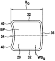
도 2에서, 실질적으로 정사각형의 관형 단면을 갖는 관형 로드 기본 프로파일(BP)이 바람직한 실시예로서의 단면도로서 도시되어 있다. 여기서 수직 관형 로드(20)의 - 정사각형 프로파일인 이 원래의 기본 프로파일(BP)은 관형 로드의 종 방향에 대해 횡 방향으로 임의의 형성부 또는 함몰부를 갖지 않는다. 외부 치수는 대략 16x16 mm이고, 따라서 정사각형 프로파일의 측면 길이로서의 높이(H(Q))도 또한 16 mm이다. 본 발명에 따른 강철 튜브 그리드 프레임의 강성의 증가의 결과로서, 1.0 mm의 관형 로드의 이전 벽 두께가 감소될 수 있고, 여기서 정사각형 프로파일은 이 경우 0.7 mm 내지 1.0 mm, 바람직하게는 0.9 mm의 감소된 벽 두께를 갖는다.In Fig. 2, a tubular rod base profile BP having a substantially square tubular cross section is shown as a sectional view as a preferred embodiment. Here, this original basic profile BP, which is a square profile of the vertical
바람직한 실시예에서, 수직 관형 로드(20)의 정사각형 프로파일은 0.8 mm의 벽 두께를 가지며, 수평 관형 로드(18)의 정사각형 프로파일은 0.9 mm의 벽 두께를 갖도록 제공된다. 이에 의해 팔레트 컨테이너의 중량 및 재료 비용은 높은 벽 강성 레벨을 유지하면서 감소될 수 있다.In a preferred embodiment, the square profile of the vertical
바람직하게는, 기본 정사각형 프로파일(BP)은 2 개의 대향하는 평행한 직선 측벽(32) 및 2 개의 대향하는 실질적으로 평행한 약간 만곡된 측벽(34, 36)을 가지며, 여기서 하나의 만곡된 측벽(34)은 내향으로 약간 오목하게 구성되고, 다른 만곡된 측벽(36)은 약간 외향으로 볼록하게 구성된다. 관형 로드(18, 20)의 약간 오목하게 내향으로 만곡된 측벽은, 2 개의 측 방향 외측 에지에서, 관형 로드의 종 방향으로 연장되는 평면 후방 라인(40)을 갖는다.Preferably, the basic square profile BP has two opposing parallel
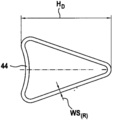
교차 위치(26)에서, 수평 관형 로드(18) 및 수직 관형 로드(20)는 약간 오목하게 내향으로 만곡된 측벽(34) 또는 2 개의 외부의 종 방향으로 연장되는 후방 라인(40)과 서로 위치되며, 관형 로드(18, 20)를 용접하기 위해 필요한 4-포인트 지지부를 형성한다. 정사각형 기본 프로파일의 약간 볼록하게 외향으로 형성된 측벽(36)은, 바람직하게 제공되는 교차 위치(26)의 영역에서, 중앙에 형성된 후방 피스(30)를 갖는 삼각형 성형 프로파일로 양측에서 가해지는 프레싱 압력의 결과로서 성형하기가 더 용이하다. 후방과 같이 증가된 부분은 간단한 유압 프레싱 집게(tongs)에 의한 냉간 성형의 결과로서 기본 프로파일 사각형 튜브로부터 생성된다.In the
교차 위치(26)의 영역에서 이러한 방식으로 가공되고 성형되며 본 발명에 따른 실질적으로 삼각형의 단면 및 중앙에 형성된 후방 피스(30)를 갖는 관형 로드 프로파일이 도 3에서 단면도로 볼 수 있다.A tubular rod profile, which is machined and shaped in this way in the region of the intersecting
16 mm의 측면 길이 또는 높이(H(Q))를 갖는 정사각형 기본 프로파일에서, 후방 팁에서의 반경의 크기에 따라, 중앙 후방 피스(30)의 팁까지 교차 관형 로드를 용접하기 위한 4-포인트 접촉 위치에 대한 기본 벽과 동일한 약간 오목하게 내향으로 만곡된 측벽으로부터의 삼각형 단면적의 영역에서 약 20.5 mm의 삼각형 관형 로드 프로파일의 높이(H(D))가 형성된다. 이 경우, 선형으로 그리고 평행한 방식으로 연장되는 2 개의 대향하는 측벽(32) 및 약간 볼록하게 외향으로 만곡된 측벽(36)은 각각 2 개의 등변 삼각형 측벽(38)으로 반으로 성형된다.In a square base profile with a side length or height (H ( Q )) of 16 mm, depending on the size of the radius at the rear tip, a 4-point contact for welding the cross tubular rod to the tip of the central rear piece 30 A height (H ( D )) of a triangular tubular rod profile of about 20.5 mm is formed in the region of the triangular cross-sectional area from the slightly concave inwardly curved sidewall, which is the same as the base wall for the location. In this case, the two opposing
성형 작업 중에, 2 개의 외향으로 지향된 험프(humps)(48)는 - 단면도로서 - 2 개의 성형된 삼각형 측벽(38)에서 약간 볼록하게 외향으로 만곡된 측벽(36)과, 평행한 방식으로 선형으로 연장되는 2 개의 대향하는 측벽(32) 사이의 2 개의 90° 굽힘부로부터 생성된다. 정사각형 기본 프로파일(BP)은 원래 원형 강철 튜브로부터 롤러 유형 롤 스탠드에서 성형되어 정사각형 프로파일을 형성한다. 이 경우, 인접한 2 개의 측벽 사이의 4 개의 90° 굽힘부는 냉간 성형에 의해 형성된다. 냉간 성형 동안, 강철 재료의 구조적 변화로 인해 강도의 국부적 증가가 발생된다. 성형된 삼각형 단면의 영역에서, 약간 볼록하게 외향으로 만곡된 측벽(36)에 인접한 2 개의 90° 굽힘부가 다시 구부러져 개방된다. 2 개의 90° 굽힘부에서의 강도의 증가의 결과로서, 역-굽힘(bending back)이 완전히 수행되지는 않고, 2 개의 등변 삼각형 측벽(38)에 2 개의 험프(48)가 남는다.During the forming operation, the two outwardly directed humps 48-as a cross-section-are linearly in a parallel fashion with the
기본 프로파일 관형 로드의 가공 및 성형은 이전에 공지된 해결 방안과 달리 여기서 그리드 벽의 평면에 수직인 방향으로 수행되는 것이 아니라, 그 대신에 그리드 벽의 평면과 평행한 방향으로 수행되고, 여기서, 중앙 후방 피스(30)를 형성하기 위해, 2 개의 대향하는 측벽에 의해 관형 로드의 제공된 영역에 동시에, 대응하여 형성된 프레싱 공구에 의해 프레싱 압력이 가해진다. 이 경우에, 이러한 프레싱 압력은 약간 볼록하게 외향으로 만곡된 측벽(36)에 이웃하거나 또는 인접한 정사각형 기본 프로파일의 영역 또는 부분에서 시작하여, 평행한 방식으로 선형으로 연장되는 2 개의 대향하는 측벽(32)에 가해진다. 이것은, 예를 들어, 서로를 향해 이동하는 2 개의 프레싱 스탬프 및 팁들을 갖는 프레싱 공구에 의해 달성될 수 있고, 상기 팁들은 이에 따라 전방에서 모따기되어, 최종 위치에서 프레싱 스탬프의 팁들 사이에 V 자형 간극이 생성되고 그리고 관형 로드의 성형된 영역의 증가된 튜브 프로파일 높이를 갖는 실질적으로 삼각형인 또는 삼각형과 같은 튜브 단면이 생성된다. 이러한 성형 작업은 또한 이에 따라 프레싱 집게 타입 공구에 의해 수행될 수 있으며, 여기서 2 개의 집게 조오(jaw)는 평행한 방식으로 선형으로 연장되는 2 개의 대향하는 측벽(32) 상의 피봇 지점을 통해 작용한다. 이 경우에, 약간 오목하게 내향으로 구부러진 측벽(34)만이 수평 및 수직 관형 로드(18, 20)의 교차 영역(26)에서 4 개의 용접 지점에 대해 성형되지 않은 상태로 유지된다.Machining and shaping of the base profile tubular rod is not performed here in a direction perpendicular to the plane of the grid wall, unlike the previously known solution, but instead in a direction parallel to the plane of the grid wall, where the center To form the
기본 프로파일 정사각형 튜브는 약간 내향으로 만곡된 기본 측벽을 가지며, 이에 의해 4-포인트 저항 용접을 위한 외측 종 방향 리브(ribs)가 생성된다. 냉간 성형 동안, 기본 측벽에 대향하는 2 개의 90° 굽힘부는 구부러져 개방되어 최대 가능한 정도까지 직선으로 되며, 기본 측벽에 대향하는 직선 측벽은 작은 반경을 갖는 비교적 좁은 굽힘부를 형성하도록 중심에서 성형된다.The base profile square tube has a slightly inwardly curved base sidewall, thereby creating outer longitudinal ribs for 4-point resistance welding. During cold forming, the two 90 ° bends facing the primary sidewalls are bent open and straightened to the maximum extent possible, and the straight sidewalls facing the primary sidewalls are molded centrally to form a relatively narrow bend with a small radius.
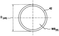
공지된 관형 로드 기본 프로파일의 다른 실시예가 단면도로서 도 4에 도시되어 있다. 이 원래의 관형 바아(bar) 기본 프로파일은 원형 튜브 프로파일(42)로서 구성되며, 대략 18 mm의 외경(D(AR)) 및 1.0 mm의 벽 두께를 갖는 원형 단면을 갖는다. 4-포인트 용접을 위해 교차 영역에서 관형 로드의 대응하는 상호 지지를 획득하기 위해, 제 1 성형 단계에서 - 다음 도 5에 도시되는 바와 같이 - 원형 관형 프로파일의 측면은 적은 양만큼 반경 방향으로 성형되어, 약간 오목한 또는 약간 내향으로 만곡된 벽 피스(44)가, 교차하는 관형 로드의 경우 4-포인트 지지부를 형성하는 외측 종 방향 리브 또는 종 방향 험프로 형성된다. 4 개의 용접 접촉점을 형성하기 위해 원형 튜브의 함몰의 결과로서, 공지된 팔레트 컨테이너의 원형 튜브는 강성 또는 굽힘 저항 모멘트의 강한 손실을 받게 된다. 이러한 강성의 손실은 도 6에 도시된 바와 같이 증가된 후방 영역(30)의 도입과 함께 실질적으로 삼각형의 단면 프로파일을 형성하도록 추가의 성형 단계에서 성형함으로써 다시 잘 보상될 수 있다. 삼각형 중공 프로파일을 갖는 이러한 실시예는 또한 증가된 후방 영역(30)의 영역에서 적어도 20 mm의 프로파일 높이(HD)를 갖는다.Another embodiment of a known tubular rod base profile is shown in FIG. 4 in cross section. This original tubular bar base profile is constructed as a
도 7은 교차 영역(26)에서 정사각형 단면을 갖는 수직 관형 로드(20)의 측 방향 부분도를 도시한다. 수평 관형 로드(18)는 기본 프로파일(BP)의 동일한 정사각형 단면을 갖는다. 교차 영역(26)에서, 수직 관형 로드(20)의 원래 정사각형 기본 프로파일(BP)은 중앙 증가된 후방 영역(30)을 갖는 실질적으로 삼각형인 중공 프로파일을 형성하도록 성형되었다. 원래의 기본 프로파일로부터 측 방향 프레싱 압력 작용에 의한 기계적 성형에 의해 구성되는 중앙 증가된 후방 영역(30)은 관형 로드의 종 방향으로 연장되는 좁은 후방을 가지며, 여기서 증가된 후방 영역(30)은 관형 로드의 종 방향으로 정의된 범위로 제한된다. 관형 로드의 종 방향으로의 증가된 후방 영역(30)의 이러한 범위는 (원형 튜브의 경우) 관형 로드의 폭 또는 관형 로드의 직경의 2 배 내지 10 배, 바람직하게는 5 배가 되도록 의도된다.7 shows a lateral partial view of a vertical
원래의 비-성형된 기본 프로파일과, 성형에 의해 구성되는 중앙 증가된 후방 영역(30) 사이에서 양 측면에는 경사지게 연장되는 전이 영역(46)이 생성된다. 이들 경사지게 연장되는 전이 영역(46)은, 상응하게 형성된 프레싱 공구에 의해 관형 로드의 교차 영역에 대해 증가된 후방 영역을 형성하기 위해, 프레싱 압력이 2 개의 대향하는 평행한 측벽에 의해 동시에 그리드 벽의 평면과 평행한 방향으로 기본 관형 프로파일의 제공된 영역에 가해짐으로써, 생성된다. 이 경우에, 프레싱 압력은 실질적으로 약간 볼록하게 외향으로 구부러진 측벽에 이웃하거나 또는 인접한 정사각형 기본 프로파일의 영역 또는 부분에서만 평행한 방식으로 선형으로 연장되는 2 개의 대향하는 측벽에 가해진다.Between the original non-formed base profile and the central augmented
성형 작업은 이 경우에, 프레싱 압력이 예를 들어, 서로를 향해 이동하는 프레싱 공구의 2 개의 프레싱 스탬프 또는 프레싱 집게 세트의 피봇 가능한 조오의, 전방에서 모따기된 2 개의 팁들에 의해, 평행하게 연장되는 2 개의 대향하는 측벽에 가해지는 방식으로 수행되고, 여기서 최종 위치에서 프레싱 스탬프 또는 프레싱 집게 세트의 조오의 팁들 사이에 V 자형 간극이 생성되고, 이에 의해 증가된 관형 프로파일 높이를 갖는 실질적으로 삼각형인 튜브 단면이 관형 로드의 성형된 영역에 형성된다.The forming operation is in this case extended in parallel by pressing pressures, for example, two pressing stamps of a pressing tool moving towards each other, or two tips chamfered in front of the pivoting jaws of a set of pressing forceps. Performed in a manner applied to two opposing sidewalls, where a V-shaped gap is created between the tips of the pressing stamp or the jaws of the pressing forceps set at the final position, thereby substantially substantially triangular tubes with increased tubular profile height A cross section is formed in the molded area of the tubular rod.
이를 위해, 도 8은 관형 그리드 프레임의 내측으로부터의 정사각형 기본 단면을 갖는 수직 관형 로드(20)의 부분 평면도로서, 성형에 의해 형성된 중앙 증가된 후방 영역(30) 및 2 개의 측면에서 인접하는 전이 영역(46)을 갖는 수직 관형 로드(20)의 성형된 삼각형 단면 영역을 도시한다. 경사진 전이 영역(46)의 종 방향 범위는 정사각형 기본 프로파일의 측벽의 높이의 대략 1 내지 2 배, 즉 15 내지 35 mm, 바람직하게는 대략 20 mm이어야 한다.To this end, FIG. 8 is a partial plan view of a vertical
유체 충전 재료로 채워지고 운송 하중의 결과로 충전 재료가 앞뒤로 밀려들어 이에 따라 압력 변화에 따라 관형 그리드 프레임의 측벽에 작용하는 IBC의 특정 사례가 고려된다면, 이것은 관형 프로파일에서 지속적으로 팽창하고 가라앉는 인장 및 압력 응력을 갖는 동적 영구 하중을 발생시키며, 이는 장기적으로 가장 큰 응력을 받는 관형 프로파일 영역에서의 균열 및 교차 위치에서 용접 지점의 파손을 초래할 수 있다. 이 경우, 관형 그리드 프레임의 측벽의 외향 벌징(bulging)은, 플라스틱 내부 컨테이너의 내부 압력의 결과로서, 탄성 복원력의 결과로서의 관형 그리드 프레임의 내향 "인덴테이션(indentation)" 또는 리바운드의 약 2 배의 크기이다. 따라서, 이 경우, 반경 방향으로 상이한 크기의 굴곡 하중이 관형 그리드 프레임의 관형 로드(= 굽힘 바아)에서 발생한다.If a specific case of IBC is filled with a fluid-filled material and the load of the filling material is pushed back and forth as a result of the transport load and thus acts on the side wall of the tubular grid frame according to the pressure change, this is a tension that continuously expands and sinks in the tubular profile And a dynamic permanent load with pressure stress, which can lead to cracks in the region of the tubular profile subject to the greatest stress in the long term and failure of the welding point at the crossing position. In this case, the outward bulging of the side walls of the tubular grid frame is about twice the inward "indentation" or rebound of the tubular grid frame as a result of the elastic restoring force, as a result of the internal pressure of the plastic inner container. It is the size. Thus, in this case, bending loads of different sizes in the radial direction occur at the tubular rod (= bending bar) of the tubular grid frame.
굽힘에 대한 저항의 크기를 축 방향 저항 모멘트(W) 또는 굽힘 저항 모멘트라고 지칭한다. 저항 모멘트는 기술 메커니즘에서, 바아 단면의 기하학적 구조(형태 및 치수)로부터만 도출되고 굽힘 바아가 부하 동안 내부 응력 발생에 대해 반대로 가하는 저항에 대한 측정인 변수를 구성한다. 이 경우, 값 측면에서 가장 큰 응력(σmax)는 중립 파이버(fiber)로부터 가장 큰 간격을 갖는 굽힘 바아의 주변 파이버에서 항상 발생한다. 바아 단면의 저항 모멘트(W)는 기하학적 관성 모멘트(I)와 간단한 기하학적 관계에 있으며, 이에 의해 부하 동안 바아의 굽힘 강성을 확립하기 위해 단면 측정 중에 성형이 계산된다. 저항 모멘트(W)는 기하학적 관성 모멘트(I)와 최대 응력(σmax)을 포함하는 몫으로 정의된다. 저항 모멘트에 대한 단위는 ㎥이다.The magnitude of resistance to bending is referred to as axial resistance moment (W) or bending resistance moment. The resistive moment is derived from the geometry (shape and dimensions) of the bar cross section in the technical mechanism and constitutes a variable that is a measure of the resistance that the bending bar exerts against internal stress generation during load. In this case, the largest stress (σ max ) in terms of value always occurs in the surrounding fibers of the bending bar with the largest spacing from the neutral fibers. The resistance moment W of the bar cross section is in a simple geometric relationship with the geometric moment of inertia I, whereby shaping is calculated during section measurement to establish the bending stiffness of the bar during load. The resistive moment W is defined as the quotient including the geometrical moment of inertia I and the maximum stress σ max . The unit for resistance moment is m3.
정사각형 기본 프로파일 및 증가된 후방 영역을 갖는 성형된 삼각형 튜브 단면의 굽힘 강성과 관련된 비교 측정 중에, 다음이 발견되었다: 정사각형 기본 프로파일은 대략 1610 mm4 정도의 기하학적 관성 모멘트(Ix)를 갖고, 대략 2000 mm4의 기하학적 관성 모멘트(Ix)는 삼각형 단면 프로파일에 대한 결과이다. 이로 인해 약 24 %의 실질적인 증가가 이루어진다.During comparative measurements related to the bending stiffness of a square base profile and a molded triangular tube section with increased rear area, the following was found: The square base profile has a geometric moment of inertia (I x ) of approximately 1610 mm 4 , approximately The geometric moment of inertia of 2000 mm 4 (I x ) is the result for a triangular cross-sectional profile. This results in a substantial increase of about 24%.
상응하는 비교 측정에서, 공지된 팔레트 컨테이너의 비-성형된 원형 튜브 프로파일에 대해, 교차 영역에서 이전에 수행된 형성 및 단면 감소에서 추가로 실질적으로 감소되는 대략 1770 mm4의 기하학적 관성 모멘트(Ix)가 발생되었다. 이에 비해, 증가된 후방 영역을 갖고 기하학적 관성 모멘트(Ix)가 2000 mm4 이상으로 증가하는 삼각형 프로파일을 형성하도록 원형 튜브 단면을 성형하여 높은 성능 증가가 또한 발생할 수 있다.In a corresponding comparative measurement, for a non-molded circular tube profile of a known pallet container, a geometric inertia moment of approximately 1770 mm 4 (I x) is further substantially reduced in the previously performed formation and cross-sectional reduction in the cross section. ) Occurred. In contrast, a high performance increase may also occur by shaping the circular tube cross section to have a triangular profile with an increased rear area and a geometrical moment of inertia (I x ) increasing to 2000 mm 4 or more.
결과적으로, 본 발명은 팔레트 컨테이너의 관형 그리드 프레임의 강성의 유리한 증가를 위해 적용이 용이하고 올바르게 기능하는 비용 효율적인 해결 방안을 제공한다. 추가의 재료가 필요하지 않고, 그 대신에 관형 로드 기본 프로파일의 특수하고 부분적인 성형만이 적용되며, 반대로, 관형 로드의 벽 두께를 감소시킴으로써 재료 및 비용 절감이 달성될 수도 있다.Consequently, the present invention provides a cost-effective solution that is easy to apply and functions properly for an advantageous increase in the rigidity of the tubular grid frame of the pallet container. No additional material is required, instead only special and partial shaping of the tubular rod base profile is applied, and conversely, material and cost savings may be achieved by reducing the wall thickness of the tubular rod.
결과적으로, 특히 위험한 유체 충전 재료를 위해 이러한 큰 컨테이너를 사용할 때, 과도한 운송 부하로 인한 손상의 발생에 대한 증가된 안전성 수준이 보장된다.As a result, an increased level of safety against the occurrence of damage due to excessive transport loads is guaranteed, especially when using such large containers for hazardous fluid-filled materials.
10 팔레트 컨테이너
H(Q) 측면 길이의 높이
12 플라스틱 내부 컨테이너
H(D) 삼각형의 높이
14 관형 그리드 프레임
WS(R) 원형 튜브의 벽 두께
16 베이스 팔레트
D(R) 원형 튜브의 직경
18 수평 관형 로드(14)
WS(Q) 정사각형 튜브의 벽 두께
20 수직 관형 로드(14)
D(AR) 원형 튜브의 외경
22 식별 패널
BP 정사각형 기본 프로파일
24 제거 피팅
26 교차 영역(14)
28 교차 조인트 영역(14)
30 증가된 후방 영역(18, 20)
32 평행한 직선 측벽
34 오목한 측벽
36 볼록한 측벽
38 삼각형 측벽
40 측 방향 후방 라인(18, 20)
42 원형 튜브 기본 프로파일(28)
44 오목한 벽 피스(42)
46 전이 영역(BP, 30)
48 험프(38)10 Pallet container H ( Q ) Side length height
12 plastic inner container H ( D ) triangle height
14 Wall thickness of tubular grid frame WS ( R ) round tube
16 Base Pallet D ( R ) Diameter of round tube
18 Horizontal tubular rod (14) WS ( Q ) Wall thickness of square tube
20 Outer diameter of vertical tubular rod (14) D ( AR ) round tube
22 identification panel BP square basic profile
24 removal fittings
26 Intersection (14)
28 Cross-joint area (14)
30 increased rear area (18, 20)
32 parallel straight sidewalls
34 concave sidewall
36 convex sidewall
38 triangular sidewall
40 lateral rear lines (18, 20)
42 Round Tube Basic Profile (28)
44 concave wall piece (42)
46 transition regions (BP, 30)
48 Hump (38)
Claims (17)
적어도 하나의 수평 및/또는 수직 관형 로드(18, 20)의 원래의 기본 프로파일은 서로 용접되는 상기 수평 및 수직 관형 로드(18, 20)의 교차 영역(26)을 통해 상기 관형 로드의 종 방향으로 미리 결정된 양만큼 연장되도록 증가된 방식으로 구성되거나 또는 증가된 후방 영역(30)이 제공되고, 상기 원래의 기본 프로파일은 실질적으로 삼각형 중공 프로파일을 형성하도록 상기 증가된 후방 영역(30)의 영역에서 성형되는 것을 특징으로 하는 팔레트 컨테이너.Horizontal and vertical tubular rods having a thin walled rigid inner container 16 comprising a thermoplastic material and tightly surrounding the plastic inner container 16 as a support covering and welded to each other at the crossing area ( 18, 20) having a tubular grid frame (tubular grid frame) 14, and the plastic inner container 12 is located and the tubular grid frame 14 is securely connected (securely) rectangular base pallet ( 12) A pallet container (10) for storing and transporting a fluid or flowable filling material, comprising:
The original basic profile of the at least one horizontal and / or vertical tubular rod 18, 20 is longitudinally transverse to the horizontal and vertical tubular rods 18, 20 of the horizontal and vertical tubular rods 18, 20 welded together. Either configured in an increased manner to extend a predetermined amount or an increased rear region 30 is provided, and the original basic profile is shaped in the region of the increased rear region 30 to form a substantially triangular hollow profile Pallet container, characterized in that.
상기 증가된 후방 영역(30)은 측 방향 프레싱(pressing) 압력 작용에 의해 상기 원래의 기본 프로파일로부터 기계적 성형에 의해 구성되며, 상기 관형 로드의 상기 종 방향으로 연장되는 좁은 후방을 갖는 것을 특징으로 하는 팔레트 컨테이너.According to claim 1,
The increased rear region 30 is constructed by mechanical molding from the original basic profile by lateral pressing pressure action, characterized in that it has a narrow rear extending in the longitudinal direction of the tubular rod. Pallet container.
상기 증가된 후방 영역(30)은 상기 관형 그리드 프레임(14)에 대해 상기 관형 로드(18, 20)의 외향으로 또는 내향으로 지향된 측면에 배치되는 것을 특징으로 하는 팔레트 컨테이너.The method of claim 1 or 2,
The increased rear area (30) is a pallet container, characterized in that it is arranged on the side facing outwardly or inwardly of the tubular rod (18, 20) relative to the tubular grid frame (14).
상기 증가된 후방 영역(30)은 상기 관형 그리드 프레임(14)에 대해 내향으로 지향된 측면에서 수직으로 연장되는 관형 로드(20)에 구성되고 그리고/또는 외향으로 지향된 측면에서 수평으로 연장되는 관형 로드(18)에 배치되는 것을 특징으로 하는 팔레트 컨테이너.The method according to any one of claims 1, 2, or 3,
The increased rear region 30 consists of a tubular rod 20 extending vertically from an inwardly directed side with respect to the tubular grid frame 14 and / or a tubular extending horizontally from an outwardly directed side. Pallet container, characterized in that placed on the rod (18).
상기 증가된 후방 영역(30)은 상기 관형 로드의 상기 종 방향으로 명확하게 한정된 범위를 갖는 것을 특징으로 하는 팔레트 컨테이너.The method of any one of claims 1, 2, 3 or 4,
The increased rear area (30) is a pallet container, characterized in that it has a clearly defined range in the longitudinal direction of the tubular rod.
상기 관형 로드의 상기 종 방향으로의 상기 증가된 후방 영역(30)의 상기 범위는 상기 관형 로드의 폭 또는 상기 관형 로드의 직경의 2 배 내지 10 배, 바람직하게는 5 배인 것을 특징으로 하는 팔레트 컨테이너.The method according to any one of claims 1, 2, 3, 4 or 5,
The range of the increased rear area 30 in the longitudinal direction of the tubular rod is 2 to 10 times, preferably 5 times the width of the tubular rod or the diameter of the tubular rod. .
상기 원래의 기본 프로파일은 정사각형 관형 프로파일로서 구성되는 것을 특징으로 하는 팔레트 컨테이너.The method of claim 6,
The original basic profile is a pallet container, characterized in that it is configured as a square tubular profile.
상기 증가된 후방 영역(30)은 상기 수직 관형 로드(20)에서만 상기 교차 영역(26)에 구성되는 것을 특징으로 하는 팔레트 컨테이너.The method according to any one of claims 1 to 7,
The increased rear area 30 is a pallet container, characterized in that it is configured in the crossing area 26 only in the vertical tubular rod 20.
상기 관형 로드(18, 20)의 상기 정사각형 프로파일은 0.8 mm 내지 1.0 mm의 벽 두께를 갖는 것을 특징으로 하는 팔레트 컨테이너.The method according to any one of claims 1 to 8,
Pallet container, characterized in that the square profile of the tubular rod (18, 20) has a wall thickness of 0.8 mm to 1.0 mm.
상기 수직 관형 로드(20)의 상기 정사각형 프로파일은 0.8 mm의 벽 두께를 가지며, 상기 수평 관형 로드(18)의 상기 정사각형 프로파일은 0.9 mm의 벽 두께를 갖는 것을 특징으로 하는 팔레트 컨테이너.The method according to any one of claims 1 to 9,
Pallet container, characterized in that the square profile of the vertical tubular rod (20) has a wall thickness of 0.8 mm, and the square profile of the horizontal tubular rod (18) has a wall thickness of 0.9 mm.
상기 정사각형 프로파일은 2 개의 대향하는 평행한 직선 측벽 및 2 개의 대향하는 평행한, 약간 만곡된 측벽을 가지며, 하나의 상기 만곡된 측벽은 내향으로 약간 오목하게 구성되고, 다른 상기 만곡된 측벽은 외향으로 약간 볼록하게 구성되는 것을 특징으로 하는 팔레트 컨테이너.The method according to any one of claims 1 to 10,
The square profile has two opposing parallel straight sidewalls and two opposing parallel, slightly curved sidewalls, one of the curved sidewalls being slightly concave inwardly, and the other curved sidewall outwardly A pallet container characterized by being slightly convex.
상기 원래의 기본 프로파일은 원형 관형 프로파일로서 구성되는 것을 특징으로 하는 팔레트 컨테이너.The method according to any one of claims 1 to 11,
Pallet container, characterized in that the original basic profile is configured as a circular tubular profile.
상기 삼각형 중공 프로파일은 상기 증가된 후방 영역(30)의 상기 영역에서 적어도 20 mm의 프로파일 높이를 갖는 것을 특징으로 하는 팔레트 컨테이너.The method according to any one of claims 1 to 7,
The triangular hollow profile has a profile height of at least 20 mm in the area of the increased rear area (30).
상기 증가된 후방 영역(30)은 바람직하게는 최대 볼록성을 갖는 상기 관형 그리드 프레임(14)의 상기 측벽의 영역에서, 즉 상기 관형 그리드 프레임(14)의 바닥으로부터 제 2 및 제 3 수평 관형 로드(18)의 중앙 영역에서 상기 교차 영역(26)에 생성되는 것을 특징으로 하는 팔레트 컨테이너.The method according to any one of claims 1 to 13,
The increased rear region 30 is preferably in the region of the side wall of the tubular grid frame 14 with maximum convexity, ie from the bottom of the tubular grid frame 14 the second and third horizontal tubular rods ( Pallet container, characterized in that generated in the cross section (26) in the central region of 18).
상응하게 형성된 프레싱 공구에 의해 상기 관형 로드의 상기 교차 영역을 위한 중앙 후방 피스(piece)를 형성하기 위해, 프레싱 압력이 2 개의 대향하는 평행한 측벽으로부터 동시에 그리드 벽의 평면과 평행한 방향으로 관형 기본 프로파일의 제공된 영역에 가해지는 것을 특징으로 하는 방법.A method for generating a triangular hollow profile from a square basic profile of a tubular grid rod of a tubular grid frame for a pallet container according to any one of claims 1 to 14,
To form a central rear piece for the intersecting region of the tubular rod by a correspondingly formed pressing tool, the pressing pressure is simultaneously from two opposing parallel side walls in a direction parallel to the plane of the grid wall in a tubular base. A method characterized in that it is applied to a given area of the profile.
평행한 방식으로 선형으로 연장되는 상기 2 개의 대향하는 측벽 상의 상기 프레싱 압력은 실질적으로 상기 약간 볼록하게 외향으로 만곡된 측벽에 이웃하거나 또는 인접한 상기 정사각형 기본 프로파일의 영역 또는 부분에만 가해지는 것을 특징으로 하는 방법.The method of claim 15,
Characterized in that the pressing pressure on the two opposing side walls extending linearly in a parallel manner is substantially applied only to the region or portion of the square base profile adjacent to or adjacent to the slightly convex outwardly curved side walls. Way.
평행하게 연장되는 상기 2 개의 대향하는 측벽 상의 상기 프레싱 압력은, 서로를 향해 이동하는 상기 프레싱 공구의 전방에서 모따기된 팁들이 최종 위치에서 상기 프레싱 공구의 상기 팁들 사이에 V 자형 간극을 생성하고 증가된 관형 프로파일 높이를 갖는 삼각형 튜브 단면이 상기 관형 로드의 성형된 영역에 형성되는 방식으로, 생성되는 것을 특징으로 하는 방법.The method of claim 15 or 16,
The pressing pressure on the two opposing sidewalls extending in parallel causes the chamfered tips in front of the pressing tool moving towards each other to create a V-shaped gap between the tips of the pressing tool in the final position and increased A method characterized in that a triangular tube cross section with a tubular profile height is produced in such a way that it is formed in a shaped area of the tubular rod.
Applications Claiming Priority (3)
| Application Number | Priority Date | Filing Date | Title |
|---|---|---|---|
| DE102017006653.1 | 2017-07-13 | ||
| DE102017006653.1A DE102017006653B4 (en) | 2017-07-13 | 2017-07-13 | Pallet container |
| PCT/EP2018/000356 WO2019011468A1 (en) | 2017-07-13 | 2018-07-13 | Pallet container |
Publications (1)
| Publication Number | Publication Date |
|---|---|
| KR20200031131A true KR20200031131A (en) | 2020-03-23 |
Family
ID=63012972
Family Applications (1)
| Application Number | Title | Priority Date | Filing Date |
|---|---|---|---|
| KR1020207004211A KR20200031131A (en) | 2017-07-13 | 2018-07-13 | Pallet container |
Country Status (20)
| Country | Link |
|---|---|
| US (1) | US11208250B2 (en) |
| EP (1) | EP3652088B1 (en) |
| JP (1) | JP7155232B2 (en) |
| KR (1) | KR20200031131A (en) |
| CN (1) | CN110869290A (en) |
| AU (1) | AU2018299640A1 (en) |
| BR (1) | BR112020000587B1 (en) |
| CA (1) | CA3069605A1 (en) |
| DE (1) | DE102017006653B4 (en) |
| ES (1) | ES2898257T3 (en) |
| HR (1) | HRP20211832T1 (en) |
| HU (1) | HUE056478T2 (en) |
| IL (1) | IL271909B2 (en) |
| MY (1) | MY201434A (en) |
| PL (1) | PL3652088T3 (en) |
| PT (1) | PT3652088T (en) |
| RU (1) | RU2762921C2 (en) |
| SG (1) | SG11202000302QA (en) |
| WO (1) | WO2019011468A1 (en) |
| ZA (1) | ZA202000563B (en) |
Families Citing this family (1)
| Publication number | Priority date | Publication date | Assignee | Title |
|---|---|---|---|---|
| US11489485B2 (en) * | 2019-01-16 | 2022-11-01 | CubeX Solar, LLC | Foldable solar power system |
Family Cites Families (19)
| Publication number | Priority date | Publication date | Assignee | Title |
|---|---|---|---|---|
| AT298203B (en) | 1968-09-20 | 1972-04-25 | Evg Entwicklung Verwert Ges | Process for the manufacture of welded steel grids |
| DE4206945C1 (en) * | 1991-03-15 | 1993-03-11 | Schuetz-Werke Gmbh & Co. Kg, 5418 Selters, De | |
| DE4322375C1 (en) * | 1993-07-06 | 1995-01-12 | Schuetz Werke Gmbh Co Kg | Process for the production of single and double-walled inner containers from sheet steel |
| DE19511723C1 (en) * | 1995-03-30 | 1996-08-29 | Protechna Sa | Pallet container |
| ATE309152T1 (en) * | 1996-09-19 | 2005-11-15 | GRID, PARTICULARLY A BASKET OF A PALLET CONTAINER | |
| DK0916592T3 (en) * | 1997-11-04 | 2002-01-28 | Royal Packaging Industry Van L | Pallet container with lattice carrier structure |
| DE10002610B4 (en) | 2000-01-22 | 2004-07-08 | Sotralentz S.A. | Containers for liquids and flowable products |
| EP1289853A2 (en) | 2000-05-25 | 2003-03-12 | MAUSER-WERKE GmbH & Co. KG | Palette container |
| CN1225384C (en) * | 2000-10-26 | 2005-11-02 | 毛瑟工厂责任有限及两合公司 | Pallet container |
| DE50112772D1 (en) * | 2000-11-23 | 2007-09-06 | Mauser Werke Gmbh | PALETTE CONTAINER |
| WO2004039691A1 (en) | 2002-11-01 | 2004-05-13 | Tri Jonk Consultancy B.V. | Pallet container |
| DE10301517B3 (en) * | 2003-01-17 | 2004-03-11 | Protechna S.A. | Transport and storage container for liquid has vertical grid rods of grid mantle enclosing inner plastics container welded to upper edge profile supporting stacked container |
| MXPA05011494A (en) | 2003-04-25 | 2005-12-15 | Mauser Werke Gmbh & Co Kg | Pallet container. |
| CN102202987B (en) * | 2008-10-02 | 2014-01-01 | 毛瑟工厂有限责任公司 | Pallet container |
| EP2617660A1 (en) | 2009-09-29 | 2013-07-24 | Greif International Holding BV. | Pallet container for liquids |
| DE102011013192A1 (en) | 2011-03-05 | 2012-09-06 | Dietmar Przytulla | pallet container |
| DE102011087927B4 (en) * | 2011-12-07 | 2018-06-21 | Protechna S.A. | Transport and storage container for liquids |
| DE202012001726U1 (en) * | 2012-02-20 | 2012-06-14 | Dietmar Przytulla | pallet container |
| DE102013205688A1 (en) * | 2013-03-28 | 2014-10-02 | Protechna S.A. | Inner container made of plastic as well as transport and storage containers for liquids with such an inner container |
-
2017
- 2017-07-13 DE DE102017006653.1A patent/DE102017006653B4/en active Active
-
2018
- 2018-07-13 MY MYPI2020000210A patent/MY201434A/en unknown
- 2018-07-13 US US16/630,279 patent/US11208250B2/en active Active
- 2018-07-13 AU AU2018299640A patent/AU2018299640A1/en active Pending
- 2018-07-13 HR HRP20211832TT patent/HRP20211832T1/en unknown
- 2018-07-13 RU RU2020106570A patent/RU2762921C2/en active
- 2018-07-13 CN CN201880046712.3A patent/CN110869290A/en active Pending
- 2018-07-13 SG SG11202000302QA patent/SG11202000302QA/en unknown
- 2018-07-13 EP EP18745495.4A patent/EP3652088B1/en active Active
- 2018-07-13 PT PT187454954T patent/PT3652088T/en unknown
- 2018-07-13 WO PCT/EP2018/000356 patent/WO2019011468A1/en active Search and Examination
- 2018-07-13 BR BR112020000587-8A patent/BR112020000587B1/en active IP Right Grant
- 2018-07-13 ES ES18745495T patent/ES2898257T3/en active Active
- 2018-07-13 KR KR1020207004211A patent/KR20200031131A/en not_active Application Discontinuation
- 2018-07-13 PL PL18745495T patent/PL3652088T3/en unknown
- 2018-07-13 JP JP2020501286A patent/JP7155232B2/en active Active
- 2018-07-13 HU HUE18745495A patent/HUE056478T2/en unknown
- 2018-07-13 CA CA3069605A patent/CA3069605A1/en active Pending
- 2018-07-13 IL IL271909A patent/IL271909B2/en unknown
-
2020
- 2020-01-28 ZA ZA2020/00563A patent/ZA202000563B/en unknown
Also Published As
| Publication number | Publication date |
|---|---|
| DE102017006653B4 (en) | 2023-10-26 |
| CN110869290A (en) | 2020-03-06 |
| ES2898257T3 (en) | 2022-03-04 |
| PL3652088T3 (en) | 2022-01-10 |
| DE102017006653A1 (en) | 2019-01-17 |
| JP7155232B2 (en) | 2022-10-18 |
| IL271909A (en) | 2020-02-27 |
| HUE056478T2 (en) | 2022-02-28 |
| BR112020000587A2 (en) | 2020-07-14 |
| CA3069605A1 (en) | 2019-01-17 |
| IL271909B2 (en) | 2023-04-01 |
| US11208250B2 (en) | 2021-12-28 |
| RU2020106570A (en) | 2021-08-13 |
| IL271909B (en) | 2022-12-01 |
| SG11202000302QA (en) | 2020-02-27 |
| EP3652088B1 (en) | 2021-09-01 |
| RU2020106570A3 (en) | 2021-10-26 |
| PT3652088T (en) | 2021-11-18 |
| JP2020527516A (en) | 2020-09-10 |
| US20200165048A1 (en) | 2020-05-28 |
| EP3652088A1 (en) | 2020-05-20 |
| MY201434A (en) | 2024-02-21 |
| RU2762921C2 (en) | 2021-12-23 |
| AU2018299640A1 (en) | 2020-02-27 |
| WO2019011468A1 (en) | 2019-01-17 |
| ZA202000563B (en) | 2022-07-27 |
| BR112020000587B1 (en) | 2023-04-18 |
| HRP20211832T1 (en) | 2022-03-04 |
Similar Documents
| Publication | Publication Date | Title |
|---|---|---|
| JP5496211B2 (en) | Pallet container | |
| US7140490B2 (en) | Pallet container | |
| US8424702B2 (en) | Pallet container for liquids | |
| KR20200031131A (en) | Pallet container | |
| AU2001269033B2 (en) | Pallet container | |
| JP6211010B2 (en) | Pallet container | |
| JP2006524611A (en) | Pallet container | |
| JP4808899B2 (en) | Pallet container | |
| AU2019275890B2 (en) | Transporting and storage container for liquids |
Legal Events
| Date | Code | Title | Description |
|---|---|---|---|
| A201 | Request for examination | ||
| E902 | Notification of reason for refusal | ||
| E601 | Decision to refuse application |