KR20200029598A - Substrate processing apparatus, method for monitoring abnormality of substrate processing apparatus, and program - Google Patents
Substrate processing apparatus, method for monitoring abnormality of substrate processing apparatus, and program Download PDFInfo
- Publication number
- KR20200029598A KR20200029598A KR1020207006145A KR20207006145A KR20200029598A KR 20200029598 A KR20200029598 A KR 20200029598A KR 1020207006145 A KR1020207006145 A KR 1020207006145A KR 20207006145 A KR20207006145 A KR 20207006145A KR 20200029598 A KR20200029598 A KR 20200029598A
- Authority
- KR
- South Korea
- Prior art keywords
- recipe
- unit
- data
- device data
- standard deviation
- Prior art date
Links
Images


Classifications
-
- G—PHYSICS
- G05—CONTROLLING; REGULATING
- G05B—CONTROL OR REGULATING SYSTEMS IN GENERAL; FUNCTIONAL ELEMENTS OF SUCH SYSTEMS; MONITORING OR TESTING ARRANGEMENTS FOR SUCH SYSTEMS OR ELEMENTS
- G05B19/00—Programme-control systems
- G05B19/02—Programme-control systems electric
- G05B19/418—Total factory control, i.e. centrally controlling a plurality of machines, e.g. direct or distributed numerical control [DNC], flexible manufacturing systems [FMS], integrated manufacturing systems [IMS], computer integrated manufacturing [CIM]
- G05B19/41875—Total factory control, i.e. centrally controlling a plurality of machines, e.g. direct or distributed numerical control [DNC], flexible manufacturing systems [FMS], integrated manufacturing systems [IMS], computer integrated manufacturing [CIM] characterised by quality surveillance of production
-
- H—ELECTRICITY
- H01—ELECTRIC ELEMENTS
- H01L—SEMICONDUCTOR DEVICES NOT COVERED BY CLASS H10
- H01L21/00—Processes or apparatus adapted for the manufacture or treatment of semiconductor or solid state devices or of parts thereof
- H01L21/67—Apparatus specially adapted for handling semiconductor or electric solid state devices during manufacture or treatment thereof; Apparatus specially adapted for handling wafers during manufacture or treatment of semiconductor or electric solid state devices or components ; Apparatus not specifically provided for elsewhere
- H01L21/67005—Apparatus not specifically provided for elsewhere
- H01L21/67242—Apparatus for monitoring, sorting or marking
- H01L21/67276—Production flow monitoring, e.g. for increasing throughput
-
- G—PHYSICS
- G05—CONTROLLING; REGULATING
- G05B—CONTROL OR REGULATING SYSTEMS IN GENERAL; FUNCTIONAL ELEMENTS OF SUCH SYSTEMS; MONITORING OR TESTING ARRANGEMENTS FOR SUCH SYSTEMS OR ELEMENTS
- G05B19/00—Programme-control systems
- G05B19/02—Programme-control systems electric
- G05B19/418—Total factory control, i.e. centrally controlling a plurality of machines, e.g. direct or distributed numerical control [DNC], flexible manufacturing systems [FMS], integrated manufacturing systems [IMS], computer integrated manufacturing [CIM]
- G05B19/4184—Total factory control, i.e. centrally controlling a plurality of machines, e.g. direct or distributed numerical control [DNC], flexible manufacturing systems [FMS], integrated manufacturing systems [IMS], computer integrated manufacturing [CIM] characterised by fault tolerance, reliability of production system
-
- G—PHYSICS
- G05—CONTROLLING; REGULATING
- G05B—CONTROL OR REGULATING SYSTEMS IN GENERAL; FUNCTIONAL ELEMENTS OF SUCH SYSTEMS; MONITORING OR TESTING ARRANGEMENTS FOR SUCH SYSTEMS OR ELEMENTS
- G05B23/00—Testing or monitoring of control systems or parts thereof
- G05B23/02—Electric testing or monitoring
- G05B23/0205—Electric testing or monitoring by means of a monitoring system capable of detecting and responding to faults
- G05B23/0218—Electric testing or monitoring by means of a monitoring system capable of detecting and responding to faults characterised by the fault detection method dealing with either existing or incipient faults
- G05B23/0224—Process history based detection method, e.g. whereby history implies the availability of large amounts of data
- G05B23/0227—Qualitative history assessment, whereby the type of data acted upon, e.g. waveforms, images or patterns, is not relevant, e.g. rule based assessment; if-then decisions
- G05B23/0235—Qualitative history assessment, whereby the type of data acted upon, e.g. waveforms, images or patterns, is not relevant, e.g. rule based assessment; if-then decisions based on a comparison with predetermined threshold or range, e.g. "classical methods", carried out during normal operation; threshold adaptation or choice; when or how to compare with the threshold
-
- H—ELECTRICITY
- H01—ELECTRIC ELEMENTS
- H01L—SEMICONDUCTOR DEVICES NOT COVERED BY CLASS H10
- H01L21/00—Processes or apparatus adapted for the manufacture or treatment of semiconductor or solid state devices or of parts thereof
- H01L21/02—Manufacture or treatment of semiconductor devices or of parts thereof
-
- G—PHYSICS
- G05—CONTROLLING; REGULATING
- G05B—CONTROL OR REGULATING SYSTEMS IN GENERAL; FUNCTIONAL ELEMENTS OF SUCH SYSTEMS; MONITORING OR TESTING ARRANGEMENTS FOR SUCH SYSTEMS OR ELEMENTS
- G05B2219/00—Program-control systems
- G05B2219/30—Nc systems
- G05B2219/31—From computer integrated manufacturing till monitoring
- G05B2219/31443—Keep track of nc program, recipe program
-
- G—PHYSICS
- G05—CONTROLLING; REGULATING
- G05B—CONTROL OR REGULATING SYSTEMS IN GENERAL; FUNCTIONAL ELEMENTS OF SUCH SYSTEMS; MONITORING OR TESTING ARRANGEMENTS FOR SUCH SYSTEMS OR ELEMENTS
- G05B2219/00—Program-control systems
- G05B2219/30—Nc systems
- G05B2219/32—Operator till task planning
- G05B2219/32368—Quality control
-
- G—PHYSICS
- G05—CONTROLLING; REGULATING
- G05B—CONTROL OR REGULATING SYSTEMS IN GENERAL; FUNCTIONAL ELEMENTS OF SUCH SYSTEMS; MONITORING OR TESTING ARRANGEMENTS FOR SUCH SYSTEMS OR ELEMENTS
- G05B2219/00—Program-control systems
- G05B2219/30—Nc systems
- G05B2219/45—Nc applications
- G05B2219/45031—Manufacturing semiconductor wafers
-
- Y—GENERAL TAGGING OF NEW TECHNOLOGICAL DEVELOPMENTS; GENERAL TAGGING OF CROSS-SECTIONAL TECHNOLOGIES SPANNING OVER SEVERAL SECTIONS OF THE IPC; TECHNICAL SUBJECTS COVERED BY FORMER USPC CROSS-REFERENCE ART COLLECTIONS [XRACs] AND DIGESTS
- Y02—TECHNOLOGIES OR APPLICATIONS FOR MITIGATION OR ADAPTATION AGAINST CLIMATE CHANGE
- Y02P—CLIMATE CHANGE MITIGATION TECHNOLOGIES IN THE PRODUCTION OR PROCESSING OF GOODS
- Y02P90/00—Enabling technologies with a potential contribution to greenhouse gas [GHG] emissions mitigation
- Y02P90/02—Total factory control, e.g. smart factories, flexible manufacturing systems [FMS] or integrated manufacturing systems [IMS]
Abstract
펌프의 전류의 값의 변화를 감시함으로써, 이상 사상을 예지하는 구성을 제공하는 것에 있다. 서브레시피를 실행하는 특정 스텝을 포함하는 프로세스 레시피를 실행시킬 때, 서브레시피를 처리 제어부에 소정 횟수 실행시켜, 기판에 소정의 처리를 실시하도록 제어하는 주컨트롤러와, 프로세스 레시피 실행 중인 장치 데이터를 수집하여, 기억부에 축적하는 장치 관리 컨트롤러를 포함하는 구성이며, 장치 관리 컨트롤러는, 장치 데이터가 축적된 상기 기억부를 검색하고, 서브레시피를 구성하는 각 스텝 중 지정 스텝에서의 장치 데이터를, 서브레시피의 실행 횟수분 취득하고, 상기 실행 횟수분 취득된 상기 장치 데이터의 제1 표준 편차를 산출하고, 산출한 제1 표준 편차를 역치와 비교하여, 역치를 초과하면 알람을 발생시키도록 구성된다.It is to provide a configuration that predicts an abnormal event by monitoring a change in the value of a pump current. When a process recipe including a specific step for executing a sub recipe is executed, a main controller is executed to execute a sub recipe for a predetermined number of times on a processing control unit to control a substrate to perform a predetermined process, and device data during process recipe execution is collected. Thus, the configuration includes a device management controller that accumulates in the storage unit, and the device management controller searches for the storage unit in which the device data is accumulated, and the device data in a designated step among the steps constituting the subrecipe is subrecipe. It is configured to acquire the number of execution times of, calculate the first standard deviation of the device data acquired for the number of execution times, compare the calculated first standard deviation with a threshold value, and generate an alarm when the threshold value is exceeded.
Description
본 발명은, 기판을 처리하는 기판 처리 장치, 예를 들어 기판에 성막 처리하는 반도체 제조 장치의 가동 상태의 파악에 관한 것이다.The present invention relates to grasping the operating state of a substrate processing apparatus for processing a substrate, for example, a semiconductor manufacturing apparatus for forming a film on a substrate.
반도체 제조 분야에서는, 장치의 가동률이나 생산 효율의 향상을 도모하기 위해서, 장치의 정보를 축적하고, 그 정보를 사용해서 장치의 이상의 해석이나 장치의 상태 감시를 행하고 있다. 예를 들어, 감시 대상물로부터 보고되는 실측값 정보를 바탕으로 SPC(Statistical Process Control: 통계적 방법) 등이 사용되어, 장치에 이상이 발생하지 않았는지 관리되고 있다. 특허문헌 1에는, SPC를 이용한 데이터의 건전성을 관리하는 방법이 기재되어 있다.In the field of semiconductor manufacturing, in order to improve the operation rate and production efficiency of a device, information of the device is accumulated, and the abnormal analysis of the device and monitoring of the state of the device are performed using the information. For example, SPC (Statistical Process Control) is used based on the measured value information reported from an object to be monitored, and it is managed whether an abnormality has not occurred in the device.
또한, 특허문헌 2에는, 프로세스 레시피에 의한 각종 모니터 데이터가 메모리에 저장되어 통계 처리 후, 통계 테이블에 평균·최소·최댓값이 저장되는 것이 기재되고, 뱃치마다의 성막시 온도의 데이터로부터 이상 시점을 검출하는 기술이 기재되어 있다.In addition,
반도체 제조 장치에서 사용되고 있는 드라이 진공 펌프는, 기름이나 액체를 진공실 내에 사용하지 않는 진공 펌프이다. 이 펌프는 케이싱 내에 로터가 들어 있어, 한 쌍의 기어에 의해 서로 반대 방향으로 동일한 주기로 회전하고 있다. 로터의 케이싱은 원래 접촉하지 않고 약간의 간극을 유지하여 회전하면서 기체를 이송 압축한다. 부생성물이 로터와 케이싱의 사이에 고이면 씹혀 부하가 걸리게 된다. 이 부하는, 펌프의 전류에 있어서, 스파이크 형상의 전류의 상승을 발생시켜, 결국 펌프의 정지로 이어지는 것으로 알려져 있다.The dry vacuum pump used in the semiconductor manufacturing apparatus is a vacuum pump that does not use oil or liquid in a vacuum chamber. The pump has a rotor in the casing, and is rotated in the same cycle in opposite directions by a pair of gears. The rotor's casing does not come into contact with the rotor, maintains a slight gap, and rotates to compress the gas. If the by-products accumulate between the rotor and the casing, they are chewed and put on a load. It is known that this load causes an increase in the spike-shaped current in the current of the pump, which eventually leads to the stop of the pump.
성막 처리에 사용되는 반도체 제조 장치는, 반응관 내의 배기를 위해서, 진공 펌프를 이용하고 있다. 이 때문에, 성막 스텝 중에서의 펌프의 전류는, 이유에 따라서는, 스파이크 형상의 전류의 상승이 발생하는 경우가 있다. 따라서, 펌프의 전류값의 최대를 역치 관리함으로써, 펌프 정지의 감시가 가능하다.The semiconductor manufacturing apparatus used for the film forming process uses a vacuum pump for exhausting the reaction tube. For this reason, the rise of the spike-shaped current may occur for the pump current during the film forming step depending on the reason. Therefore, it is possible to monitor the pump stop by threshold management of the maximum of the current value of the pump.
그러나, 펌프 전류의 최댓값만으로 감시하면, 스파이크 형상의 전류 상승의 빈도에 관계없이, 1회라도 큰 부하가 걸리는 것만으로, 이상이라고 판단해버린다는 과제가 있다. 또한, 실제의 펌프 전류의 값을 보면서 역치의 조정이 필요해서, 최적값을 찾는 것이 어렵다는 과제가 있다.However, when monitoring only the maximum value of the pump current, there is a problem that it is judged as an abnormality only by applying a large load even once, regardless of the frequency of spike-shaped current rise. In addition, it is necessary to adjust the threshold while looking at the actual value of the pump current, which makes it difficult to find the optimum value.
본 발명의 목적은, 펌프의 전류의 값의 변화를 감시함으로써, 이상 사상을 예지하는 구성을 제공하는 데 있다.An object of the present invention is to provide a configuration that predicts an abnormal event by monitoring a change in the value of the current in the pump.
본 발명의 일 형태에 의하면,According to one aspect of the present invention,
서브레시피를 실행하는 특정 스텝을 포함하는 프로세스 레시피를 실행시킬 때, 서브레시피를 처리 제어부에 소정 횟수 실행시켜, 기판에 소정의 처리를 실시하도록 제어하는 주컨트롤러와, 프로세스 레시피 실행 중인 장치 데이터를 수집하여, 기억부에 축적하는 장치 관리 컨트롤러를 포함하는 구성이며,When a process recipe including a specific step for executing a sub recipe is executed, a main controller is executed to execute a sub recipe for a predetermined number of times on a processing control unit to control a substrate to perform a predetermined process, and device data during process recipe execution is collected. Thus, the configuration includes a device management controller that accumulates in the storage unit,
장치 관리 컨트롤러는, 장치 데이터가 축적된 기억부를 검색하여, 서브레시피를 구성하는 각 스텝 중 지정 스텝에서의 장치 데이터를, 서브레시피의 실행 횟수분 취득하고, 상기 실행 횟수분 취득된 상기 장치 데이터의 취득한 상기 장치 데이터의 값과 상기 서브레시피를 실행한 횟수로부터 제1 표준 편차를 산출하고, 산출한 제1 표준 편차값을 역치와 비교하여, 역치를 초과하면 알람을 발생시키도록 구성된다.The device management controller searches for a storage unit in which device data is accumulated, acquires device data in a designated step among the steps constituting the subrecipe for the number of execution times of the subrecipe, and of the acquired device data for the number of execution times. It is configured to calculate a first standard deviation from the acquired value of the device data and the number of times the subrecipe is executed, compare the calculated first standard deviation value with a threshold value, and generate an alarm when the threshold value is exceeded.
본 발명에 따르면, 펌프의 전류의 변화를 감시함으로써, 펌프가 정지하는 징조를 포착할 수 있다.According to the present invention, by monitoring the change in the current of the pump, it is possible to capture the sign that the pump is stopped.
도 1은 본 발명의 일 실시 형태에 적합하게 사용되는 기판 처리 장치를 도시하는 사시도이다.
도 2는 본 발명의 일 실시 형태에 적합하게 사용되는 기판 처리 장치를 나타내는 측단면도이다.
도 3은 본 발명의 일 실시 형태에 적합하게 사용되는 제어 시스템의 기능 구성을 도시하는 도면이다.
도 4는 본 발명의 일 실시 형태에 적합하게 사용되는 주컨트롤러의 기능 구성을 도시하는 도면이다.
도 5는 본 발명의 일 실시 형태에 적합하게 사용되는 장치 관리 컨트롤러의 기능 구성을 설명하는 도면이다.
도 6은 본 발명의 일 실시 형태에 적합하게 사용되는 장치 상태 감시부의 기능 구성을 설명하는 도면이다.
도 7은 진공 펌프의 전류값과 서브레시피의 관계를 개념적으로 도시하는 도면이다.
도 8은 실시예에 관한 장치 상태 감시부에서의 장치 데이터의 1차 통계 데이터를 설명하는 도면이다.
도 9는 실시예에 관한 펌프 전류 이상 감시 프로그램의 플로우를 설명하는 도면이다.
도 10은 실시예에 관한 펌프 전류 이상 감시 프로그램에서 이용되는 표준 편차의 산출식이다.
도 11은 비교예에 관한 펌프 전류의 최댓값을 감시한 경우의 설명도이다.
도 12는 실시예에 관한 펌프 전류의 최댓값의 표준 편차를 감시한 경우의 설명도이다.1 is a perspective view showing a substrate processing apparatus suitably used in one embodiment of the present invention.
2 is a side cross-sectional view showing a substrate processing apparatus suitably used in one embodiment of the present invention.
3 is a diagram showing a functional configuration of a control system used suitably for one embodiment of the present invention.
4 is a diagram showing a functional configuration of a main controller used suitably for one embodiment of the present invention.
It is a figure explaining the functional structure of the apparatus management controller used suitably for one Embodiment of this invention.
It is a figure explaining the functional structure of the apparatus state monitoring part used suitably for one Embodiment of this invention.
7 is a diagram conceptually showing a relationship between a current value and a sub recipe of a vacuum pump.
8 is a view for explaining primary statistical data of device data in the device status monitoring unit according to the embodiment.
It is a figure explaining the flow of the pump current abnormality monitoring program concerning an Example.
10 is a formula for calculating the standard deviation used in the pump current abnormality monitoring program according to the embodiment.
11 is an explanatory diagram when the maximum value of the pump current according to the comparative example is monitored.
12 is an explanatory diagram when the standard deviation of the maximum value of the pump current according to the embodiment is monitored.
(1) 기판 처리 장치의 구성(1) Configuration of substrate processing apparatus
이하, 실시 형태에 대해서, 도면을 사용하여 설명한다. 단, 이하의 설명에서, 동일 구성 요소에는 동일 부호를 붙여 반복 설명을 생략하는 경우가 있다. 또한, 도면은 설명을 보다 명확하게 하기 위해서, 실제의 양태에 비해, 각 부의 폭, 두께, 형상 등에 대하여 모식적으로 표현될 경우가 있지만, 어디까지나 일례이며, 본 발명의 해석을 한정하는 것은 아니다.Hereinafter, embodiments will be described with reference to the drawings. However, in the following description, the same components are given the same reference numerals, and repeated descriptions are sometimes omitted. In addition, in order to make the description more clear, the width, thickness, shape, etc. of each part may be schematically expressed in comparison with the actual aspect, but it is an example only and does not limit the interpretation of the present invention. .
(기판 처리 장치의 개요)(Overview of substrate processing equipment)
이하, 도면을 참조하면서 본 발명의 일 실시 형태에 대하여 설명한다. 먼저, 도 1, 도 2에서, 본 발명이 실시되는 기판 처리 장치(이후, 간단히 장치라고도 함)(1)에 대하여 설명한다.Hereinafter, one embodiment of the present invention will be described with reference to the drawings. First, in FIG. 1 and FIG. 2, the substrate processing apparatus (hereinafter also simply referred to as apparatus) 1 in which the present invention is implemented will be described.
기판 처리 장치(1)는 하우징(2)을 구비하고, 해당 하우징(2)의 정면 벽(3)의 하부에는 메인터넌스 가능하도록 마련된 개구부(정면 메인터넌스구)(4)가 개방 형성되고, 해당 개구부(4)는 정면 메인터넌스 도어(5)에 의해 개폐된다.The
하우징(2)의 정면 벽(3)에는 포드 반입 반출구(6)가 하우징(2)의 내외를 연통하도록 개방 형성되어 있고, 포드 반입 반출구(6)는 프론트 셔터(7)에 의해 개폐되고, 포드 반입 반출구(6)의 정면 전방측에는 로드 포트(8)가 설치되어 있고, 해당 로드 포트(8)는 적재된 포드(9)를 위치 정렬하도록 구성되어 있다. 해당 포드(9)는 밀폐식 기판 반송 용기이며, 도시하지 않은 공정내 반송 장치에 의해 로드 포트(8) 상에 반입되고, 또한, 해당 로드 포트(8) 상으로부터 반출되도록 되어 있다.On the front wall 3 of the
하우징(2) 내의 전후 방향의 대략 중앙부에서의 상부에는, 회전식 포드 선반(11)이 설치되어 있고, 해당 회전식 포드 선반(11)은 복수개의 포드(9)를 저장하도록 구성되어 있다. 회전식 포드 선반(11)은 수직으로 세워 설치되어 간헐 회전되는 지주(12)와, 해당 지주(12)에 상중하단의 각 위치에서 방사형으로 지지된 복수단의 선반판(13)을 구비하고 있고, 해당 선반판(13)은 상기 포드(9)를 복수개씩 적재한 상태에서 저장하도록 구성되어 있다. 회전식 포드 선반(11)의 하방에는, 포드 오프너(14)가 마련되고, 해당 포드 오프너(14)는 포드(9)를 적재하고, 또한 해당 포드(9)의 덮개를 개폐 가능한 구성을 갖고 있다.A
로드 포트(8)와 회전식 포드 선반(11), 포드 오프너(14)와의 사이에는, 포드 반송 기구(15)가 설치되어 있고, 해당 포드 반송 기구(15)는 포드(9)를 보유 지지하여 승강 가능, 수평 방향으로 진퇴 가능하게 되어 있어, 로드 포트(8), 회전식 포드 선반(11), 포드 오프너(14)와의 사이에서 포드(9)를 반송하도록 구성되어 있다.A
하우징(2) 내의 전후 방향의 대략 중앙부에서의 하부에는, 서브 하우징(16)이 후단부에 걸쳐서 마련되어 있다. 해당 서브 하우징(16)의 정면 벽(17)에는 웨이퍼(이후, 기판이라고도 함)(18)를 서브 하우징(16) 내에 대하여 반입 반출하기 위한 웨이퍼 반입 반출구(19)가 한 쌍, 수직 방향으로 상하 2단으로 배열되어 개방 형성되어 있고, 상하단의 웨이퍼 반입 반출구(19)에 대하여 포드 오프너(14)가 각각 마련되어 있다.A
포드 오프너(14)는 포드(9)를 적재하는 적재대(21)와, 포드(9)의 덮개를 개폐하는 개폐 기구(22)를 구비하고 있다. 포드 오프너(14)는 적재대(21)에 적재된 포드(9)의 덮개를 개폐 기구(22)에 의해 개폐함으로써, 포드(9)의 웨이퍼 출입구를 개폐하도록 구성되어 있다.The
서브 하우징(16)은 포드 반송 기구(15)나 회전식 포드 선반(11)이 배치되어 있는 공간(포드 반송 공간)으로부터 기밀하게 되어 있는 이동 탑재실(23)을 구성하고 있다. 해당 이동 탑재실(23)의 전방측 영역에는 웨이퍼 이동 탑재 기구(기판 이동 탑재 기구)(24)가 설치되어 있고, 해당 기판 이동 탑재 기구(24)는 기판(18)을 적재하는 소요 매수(도시에서는 5매)의 웨이퍼 적재 플레이트(25)를 구비하고, 해당 웨이퍼 적재 플레이트(25)는 수평 방향으로 직선 구동 가능, 수평 방향으로 회전 가능, 또한 승강 가능하게 되어 있다. 기판 이동 탑재 기구(24)는 보트(기판 보유 지지체)(26)에 대하여 기판(18)을 장전 및 배출하도록 구성되어 있다.The
이동 탑재실(23)의 후방측 영역에는, 보트(26)를 수용하여 대기시키는 대기부(27)가 구성되고, 해당 대기부(27)의 상방에는 종형의 처리로(28)가 마련되어 있다. 해당 처리로(28)는 내부에 처리실(반응실)(29)을 형성하고, 해당 처리실(29)의 하단부는 노구부로 되어 있고, 해당 노구부는 노구 셔터(31)에 의해 개폐되도록 되어 있다.In the rear-side region of the
하우징(2)의 우측 단부와 서브 하우징(16)의 대기부(27)의 우측 단부의 사이에는 보트(26)를 승강시키는 위한 승강 기구로서의 보트 엘리베이터(32)가 설치되어 있다. 해당 보트 엘리베이터(32)의 승강 대에 연결된 암(33)에는 덮개로서의 시일 캡(34)이 수평하게 설치되어 있고, 해당 덮개(34)는 보트(26)를 수직으로 지지하고, 해당 보트(26)를 처리실(29)에 장입한 상태에서 노구부를 기밀하게 폐색 가능하게 되어 있다.Between the right end of the
보트(26)는 복수매(예를 들어, 50매 내지 125매 정도)의 기판(18)을 그 중심을 일치시켜 수평 자세로 다단으로 보유 지지하도록 구성되어 있다.The
보트 엘리베이터(32)측과 대향한 위치에는 클린 유닛(35)이 배치되고, 해당 클린 유닛(35)은 청정화된 분위기 또는 불활성 가스인 클린에어(36)를 공급하도록 공급 팬 및 방진 필터로 구성되어 있다. 기판 이동 탑재 기구(24)와 클린 유닛(35)의 사이에는, 기판(18)의 원주 방향의 위치를 정합시키는 기판 정합 장치로서의 노치 맞춤 장치(도시하지 않음)가 설치되어 있다.A
클린 유닛(35)으로부터 분출된 클린에어(36)는, 노치 맞춤 장치(도시하지 않음) 및 기판 이동 탑재 기구(24), 보트(26)에 유통된 후에, 도시하지 않은 덕트에 의해 흡입되어, 하우징(2)의 외부로 배기가 이루어지거나, 또는 클린 유닛(35)에 의해 이동 탑재실(23) 내에 분출되도록 구성되어 있다.The
이어서, 기판 처리 장치(1)의 작동에 대하여 설명한다.Next, the operation of the
포드(9)가 로드 포트(8)에 공급되면, 포드 반입 반출구(6)가 프론트 셔터(7)에 의해 개방된다. 로드 포트(8) 상의 포드(9)는 포드 반송 장치(15)에 의해 하우징(2)의 내부에 포드 반입 반출구(6)를 통해서 반입되어, 회전식 포드 선반(11)의 지정된 선반판(13)에 적재된다. 포드(9)는 회전식 포드 선반(11)에서 일시적으로 보관된 후, 포드 반송 장치(15)에 의해 선반판(13)으로부터 어느 하나의 포드 오프너(14)에 반송되어 적재대(21)에 이동 탑재되거나, 또는 로드 포트(8)로부터 직접 적재대(21)에 이동 탑재된다.When the pod 9 is supplied to the load port 8, the pod carry-in / out
이때, 웨이퍼 반입 반출구(19)는 개폐 기구(22)에 의해 폐쇄되고, 이동 탑재실(23)은 클린에어(36)가 유통되어, 충만되어 있다. 이동 탑재실(23)에는 클린에어(36)로서 질소 가스가 충만되기 때문에, 이동 탑재실(23)의 산소 농도는, 하우징(2)의 내부의 산소 농도보다도 낮다.At this time, the wafer carry-in / out
적재대(21)에 적재된 포드(9)는 그 개구 측단면이 서브 하우징(16)의 정면 벽(17)에서의 웨이퍼 반입 반출구(19)의 개구 가장자리부에 압박되어짐과 함께, 덮개가 개폐 기구(22)에 의해 분리되어, 웨이퍼 출입구가 개방된다.The pod 9 loaded on the mounting table 21 has its opening side cross-section pressed against the opening edge of the wafer carry-in / out
포드(9)가 상기 포드 오프너(14)에 의해 개방되면, 기판(18)은 포드(9)로부터 기판 이동 탑재 기구(24)에 의해 취출되어, 노치 맞춤 장치(도시하지 않음)에 이송되고, 해당 노치 맞춤 장치에서 기판(18)을 정합한 후, 기판 이동 탑재 기구(24)는 기판(18)을 이동 탑재실(23)의 후방에 있는 대기부(27)에 반입하여, 보트(26)에 장전(차징) 한다.When the pod 9 is opened by the
보트(26)에 기판(18)을 전달한 기판 이동 탑재 기구(24)는 포드(9)로 돌아가서, 다음 기판(18)을 보트(26)에 장전한다. 한쪽(상단 또는 하단)의 포드 오프너(14)에서의 기판 이동 탑재 기구(24)에 의해 기판(18)의 보트(26)에의 장전 작업 중에, 다른 쪽(하단 또는 상단)의 포드 오프너(14)에는 회전식 포드 선반(11)으로부터 다른 포드(9)가 포드 반송 장치(15)에 의해 반송되어 이동 탑재되어, 다른 쪽의 포드 오프너(14)에 의한 포드(9)의 개방 작업이 동시 진행된다.The substrate
미리 지정된 매수의 기판(18)이 보트(26)에 장전되면 노구 셔터(31)에 의해 폐쇄되어 있던 처리로(28)의 노구부가 노구 셔터(31)에 의해 개방된다. 계속해서, 보트(26)는 보트 엘리베이터(32)에 의해 상승되어, 처리실(29)에 반입(로딩)된다.When a predetermined number of
로딩 후에는 시일 캡(34)에 의해 노구부가 기밀하게 폐색된다. 또한, 본 실시 형태에서, 이 타이밍에(로딩 후), 처리실(29)이 불활성 가스로 치환되는 퍼지 공정(프리퍼지 공정)을 갖는다.After loading, the furnace cap is hermetically closed by the
처리실(29)이 원하는 압력(진공도)으로 되도록, 진공 펌프 등의 가스 배기 기구(도시하지 않음)에 의해 진공 배기된다. 또한, 처리실(29)이 원하는 온도 분포가 되도록 히터 구동부(도시하지 않음)에 의해 소정 온도까지 가열된다. 또한, 가스 공급 기구(도시하지 않음)에 의해, 소정의 유량으로 제어된 처리 가스가 공급되고, 처리 가스가 처리실(29)을 유통하는 과정에서, 기판(18)의 표면과 접촉하여, 기판(18)의 표면 상에 소정의 처리가 실시된다. 또한, 반응 후의 처리 가스는, 가스 배기 기구에 의해 처리실(29)로부터 배기된다.The processing chamber 29 is evacuated by a gas exhaust mechanism (not shown) such as a vacuum pump so as to achieve a desired pressure (vacuum degree). Further, the processing chamber 29 is heated to a predetermined temperature by a heater driving unit (not shown) so as to achieve a desired temperature distribution. In addition, a process gas controlled at a predetermined flow rate is supplied by a gas supply mechanism (not shown), and the process gas is in contact with the surface of the
미리 설정된 처리 시간이 경과하면, 가스 공급 기구에 의해 불활성 가스 공급원(도시하지 않음)으로부터 불활성 가스가 공급되어, 처리실(29)이 불활성 가스로 치환됨과 함께, 처리실(29)의 압력이 상압으로 복귀된다(애프터 퍼지 공정). 그리고, 보트 엘리베이터(32)에 의해 시일 캡(34)을 개재하여 보트(26)가 강하된다.When a preset processing time has elapsed, an inert gas is supplied from an inert gas supply source (not shown) by a gas supply mechanism, the processing chamber 29 is replaced with an inert gas, and the pressure in the processing chamber 29 returns to normal pressure. (After-purge process). Then, the
처리 후의 기판(18)의 반출에 대해서는, 상기 설명과 역의 수순으로, 기판(18) 및 포드(9)는 상기 하우징(2)의 외부로 배출된다. 미처리 기판(18)이, 또한 상기 보트(26)에 장전되어, 기판(18)의 처리가 반복된다.About the carrying out of the board |
(제어 시스템(200)의 기능 구성)(Functional configuration of the control system 200)
이어서, 도 3을 참조하여, 조작부로서의 주컨트롤러(201)를 중심으로 한 제어 시스템(200)의 기능 구성에 대하여 설명한다. 도 3에 도시한 바와 같이, 제어 시스템(200)은, 주컨트롤러(201)와, 반송 제어부로서의 반송계 컨트롤러(211)와, 처리 제어부로서의 프로세스계 컨트롤러(212)와, 데이터 감시부로서의 장치 관리 컨트롤러(215)를 구비하고 있다. 장치 관리 컨트롤러(215)는, 데이터 수집 컨트롤러로서 기능하여, 장치(1) 내외의 장치 데이터를 수집하고, 장치(1) 내의 장치 데이터(DD)의 건전성을 감시한다. 본 실시 형태에서는, 제어 시스템(200)은, 장치(1) 내에 수용되어 있다.Next, with reference to FIG. 3, the functional structure of the
여기서, 장치 데이터(DD)란, 장치(1)가 기판(18)을 처리할 때의 처리 온도, 처리 압력, 처리 가스의 유량 등 기판 처리에 관한 데이터(이후, 제어 파라미터라고도 함)나, 제조한 제품 기판의 품질(예를 들어, 성막한 막 두께, 및 해당 막 두께의 누적값 등)에 관한 데이터나, 장치(1)의 구성 부품(석영 반응관, 히터, 밸브, MFC 등)에 관한 데이터(예를 들어, 설정값, 실측값) 등, 기판 처리 장치(1)가 기판(18)을 처리할 때 각 구성 부품을 동작시킴으로써 발생하는 데이터이다.Here, the device data DD is data related to substrate processing (hereinafter, also referred to as control parameters) such as processing temperature, processing pressure, and flow rate of processing gas when the
또한, 레시피 실행 중에 수집되는 데이터는, 프로세스 데이터라고 칭하는 경우가 있다. 예를 들어, 레시피 개시부터 종료까지의 특정 간격(예를 들어, 1초 등) 데이터로서의 미처리 파형 데이터나 레시피 내의 각 스텝의 통계량 데이터 등의 프로세스 데이터도 장치 데이터(DD)에 포함한다. 또한, 통계량 데이터에는, 최댓값, 최솟값, 평균값 등이 포함된다. 또한, 레시피가 실행되고 있지 않을 때(예를 들어, 장치에 기판이 투입되어 있지 않은 아이들 시)의 다양한 장치 이벤트를 나타내는 이벤트 데이터(예를 들어, 메인터넌스 이력을 나타내는 데이터)도 장치 데이터(DD)에 포함된다.Note that data collected during the execution of the recipe may be referred to as process data. For example, device data DD also includes process data such as raw waveform data as data at a specific interval (for example, 1 second, etc.) from the start to the end of the recipe, and statistical data of each step in the recipe. In addition, the statistic data includes a maximum value, a minimum value, and an average value. In addition, event data (for example, data indicating maintenance history) indicating various device events when a recipe is not being executed (for example, when idle is not input to the device) is also device data DD. Is included in.
주컨트롤러(201)는, 예를 들어 100BASE-T 등의 LAN 회선 LAN1에 의해, 반송계 컨트롤러(211) 및 프로세스계 컨트롤러(212)와 전기적으로 접속되어 있기 때문에, 각 장치 데이터(DD)의 송수신이나 각 파일의 다운로드 및 업로드 등이 가능한 구성으로 되어 있다.Since the
조작부(201)에는, 외부 기억 장치로서의 기록 매체(예를 들어 USB 키 등)가 삽입 분리되는 장착부로서의 포트가 마련되어 있다. 조작부(201)에는, 이 포트에 대응하는 OS가 인스톨되어 있다. 또한, 조작부(201)에는, 외부의 상위 컴퓨터(300)나 관리 장치(310)가, 예를 들어 100BASE-T 등의 통신 네트워크 LAN2를 통해서 접속된다. 이 때문에, 기판 처리 장치(1)가 클린 룸 내에 설치되어 있는 경우에도, 상위 컴퓨터(300)나 관리 장치(310)가 클린 룸외의 사무소 등에 배치되는 것이 가능하다.The
장치 관리 컨트롤러(215)는, 조작부(201)와 LAN 회선으로 접속되어, 조작부(201)로부터 장치 데이터(DD)를 수집하고, 장치의 가동 상태를 정량화하여 화면에 표시하도록 구성되어 있다. 또한, 장치 관리 컨트롤러(215)에 대해서는, 나중에 상세하게 설명한다.The
반송계 컨트롤러(211)는, 주로 회전식 포드 선반(11), 보트 엘리베이터(32), 포드 반송 장치(15), 기판 이동 탑재 기구(24), 보트(26) 및 회전 기구(도시하지 않음)에 의해 구성되는 기판 반송계(211A)에 접속되어 있다. 반송계 컨트롤러(211)는, 회전식 포드 선반(11), 보트 엘리베이터(32), 포드 반송 장치(15), 기판 이동 탑재 기구(24), 보트(26) 및 회전 기구(도시하지 않음)의 반송 동작을 각각 제어하도록 구성되어 있다. 특히, 반송계 컨트롤러(211)는, 모션 컨트롤러(211a)를 통해서 보트 엘리베이터(32), 포드 반송 장치(15), 기판 이동 탑재 기구(24)의 반송 동작을 각각 제어하도록 구성되어 있다.The conveying
프로세스계 컨트롤러(212)는, 온도 컨트롤러(212a), 압력 컨트롤러(212b), 가스 유량 컨트롤러(212c), 시퀀서(212d)를 구비하고 있다. 이들 온도 컨트롤러(212a), 압력 컨트롤러(212b), 가스 유량 컨트롤러(212c), 시퀀서(212d)는, 서브 컨트롤러를 구성하고, 프로세스계 컨트롤러(212)와 전기적으로 접속되어 있기 때문에, 각 장치 데이터(DD)의 송수신이나 각 파일의 다운로드 및 업로드 등이 가능하게 되어 있다. 또한, 프로세스계 컨트롤러(212)와 서브 컨트롤러는, 별체로 도시되어 있지만, 일체 구성이어도 상관없다.The
온도 컨트롤러(212a)에는, 주로 히터 및 온도 센서 등에 의해 구성되는 가열 기구(212A)가 접속되어 있다. 온도 컨트롤러(212a)는, 처리로(28)의 히터의 온도를 제어함으로써 처리로(28) 내의 온도를 조절하도록 구성되어 있다. 또한, 온도 컨트롤러(212a)는, 사이리스터의 스위칭(온/오프) 제어를 행하여, 히터 소선(素線)에 공급하는 전력을 제어하도록 구성되어 있다.The
압력 컨트롤러(212b)에는, 주로 압력 센서, 압력 밸브로서의 APC 밸브 및 진공 펌프에 의해 구성되는 가스 배기 기구(212B)가 접속되어 있다. 압력 컨트롤러(212b)는, 압력 센서에 의해 검지된 압력값에 기초하여, 처리실(29) 내의 압력이 원하는 타이밍에 원하는 압력으로 되도록, APC 밸브의 개방도 및 진공 펌프의 스위칭(온/오프)을 제어하도록 구성되어 있다.The
가스 유량 컨트롤러(212c)는 MFC에 의해 구성된다. 시퀀서(212d)는, 처리 가스 공급관이나 퍼지 가스 공급관으로부터의 가스의 공급이나 정지를, 밸브(212D)를 개폐시킴으로써 제어하도록 구성되어 있다. 또한, 프로세스계 컨트롤러(212)는, 처리실(29) 내에 공급하는 가스의 유량이 원하는 타이밍에 원하는 유량이 되도록, MFC(212c), 밸브(212D)를 제어하도록 구성되어 있다.The
또한, 본 실시 형태에 따른 주컨트롤러(201), 반송계 컨트롤러(211), 프로세스계 컨트롤러(212), 장치 관리 컨트롤러(215)는, 전용의 시스템에 구애되지 않고, 통상의 컴퓨터 시스템을 사용하여 실현 가능하다. 예를 들어, 범용 컴퓨터에, 상술한 처리를 실행하기 위한 프로그램을 저장한 기록 매체(USB 키 등)로부터 당해 프로그램을 인스톨함으로써, 소정의 처리를 실행하는 각 컨트롤러를 구성할 수 있다.Note that the
그리고, 이들 프로그램을 공급하기 위한 수단은 임의이다. 상술한 바와 같이 소정의 기록 매체를 통해서 공급할 수 있는 것 외에, 예를 들어 통신 회선, 통신 네트워크, 통신 시스템 등을 통해서 공급해도 된다. 이 경우, 예를 들어 통신 네트워크의 게시판에 당해 프로그램을 게시하고, 이 프로그램을 네트워크를 통해서 반송파에 중첩하여 제공해도 된다. 그리고, 이렇게 제공된 프로그램을 기동하여, OS의 제어 하에서, 다른 애플리케이션 프로그램과 마찬가지로 실행함으로써, 소정의 처리를 실행할 수 있다.And the means for supplying these programs is arbitrary. In addition to being able to supply through a predetermined recording medium as described above, for example, it may be supplied through a communication line, a communication network, a communication system, or the like. In this case, for example, the program may be posted on a bulletin board of a communication network, and the program may be provided superimposed on a carrier through a network. Then, by starting the provided program and executing it under the control of the OS like any other application program, predetermined processing can be executed.
(주컨트롤러(201)의 구성)(Composition of main controller 201)
이어서, 주컨트롤러(201)의 구성을, 도 4를 참조하면서 설명한다.Next, the configuration of the
주컨트롤러(201)는, 주컨트롤러 제어부(220), 주컨트롤러 기억부로서의 하드 디스크(222), 각종 정보를 표시하는 표시부와, 조작자로부터의 각종 지시를 접수하는 입력부를 포함하는 조작 표시부(227), 장치(1) 내외와 통신하는 주컨트롤러 통신부로서의 송수신 모듈(228)을 포함하도록 구성된다. 주컨트롤러 제어부(220)는, 처리부로서의 CPU(중앙 처리 장치)(224)나, 일시 기억부로서의 메모리(RAM, ROM 등)(226)를 포함하고, 시계 기능(도시하지 않음)을 구비한 컴퓨터로서 구성되어 있다.The
하드 디스크(222)에는, 기판의 처리 조건 및 처리 수순이 정의된 레시피 등의 각 레시피 파일, 이들 각 레시피 파일을 실행시키기 위한 제어 프로그램 파일, 레시피를 실행하기 위한 파라미터가 정의된 파라미터 파일, 또한 에러 처리 프로그램 파일 및 에러 처리의 파라미터 파일 외에, 프로세스 파라미터를 입력하는 입력 화면을 포함하는 각종 화면 파일, 각종 아이콘 파일 등(모두 도시하지 않음)이 저장되어 있다.In the
또한, 조작 표시부(227)의 조작 화면에는, 도 3에 도시하는, 기판 반송계(211A)나 기판 처리계(가열 기구(212A), 가스 배기 기구(212B) 및 가스 공급계(212C))에의 동작 지시를 입력하거나 하는 입력부로서의 각 조작 버튼을 마련하는 것도 가능하다.On the operation screen of the
조작 표시부(227)에는, 장치(1)를 조작하기 위한 조작 화면이 표시되도록 구성되어 있다. 조작 표시부(227)는, 조작 화면을 통해서 기판 처리 장치(100) 내에서 생성되는 장치 데이터(DD)에 기초한 정보를 조작 화면에 표시한다. 조작 표시부(227)의 조작 화면은, 예를 들어 액정을 사용한 터치 패널이다. 조작 표시부(227)는, 조작 화면으로부터의 작업자의 입력 데이터(입력 지시)를 접수하여, 입력 데이터를 주컨트롤러(201)에 송신한다. 또한, 조작 표시부(227)는, 메모리(RAM)(226) 등에 전개된 레시피, 또는 주컨트롤러 기억부(222)에 저장된 복수의 레시피 중 임의의 기판 처리 레시피(이후, 프로세스 레시피라고도 함)를 실행시키는 지시(제어 지시)를 접수하여, 주컨트롤러 제어부(220)에 송신한다.The
또한, 본 실시 형태에서는, 장치 관리 컨트롤러(215)가 기동 시에, 각종 프로그램 등을 실행함으로써, 저장된 각 화면 파일 및 데이터 테이블을 전개하고, 장치 데이터(DD)를 판독함으로써, 장치의 가동 상태가 나타나는 각 화면이, 조작 표시부(227)에 표시되도록 구성된다.In addition, in the present embodiment, when the
주컨트롤러 통신부(228)에는, 스위칭 허브 등이 접속되어 있고, 주컨트롤러(201)가, 네트워크를 통해서, 외부의 컴퓨터(300)나 장치(1) 내의 다른 컨트롤러(211, 212, 215) 등과, 데이터의 송신 및 수신을 행하도록 구성되어 있다.A switching hub or the like is connected to the main
또한, 주컨트롤러(201)는, 도시하지 않은 네트워크를 통해서 외부의 상위 컴퓨터(300), 예를 들어 호스트 컴퓨터에 대하여 장치(1)의 상태 등 장치 데이터(DD)를 송신한다. 또한, 장치(1)의 기판 처리 동작은, 주컨트롤러 기억부(222)에 기억되어 있는 각 레시피 파일, 각 파라미터 파일 등에 기초하여, 제어 시스템(200)에 의해 제어된다.Further, the
(기판 처리 방법)(Substrate processing method)
이어서, 본 실시 형태에 따른 장치(1)를 사용하여 실시하는, 소정의 처리 공정을 갖는 기판 처리 방법에 대하여 설명한다. 여기서, 소정의 처리 공정은, 반도체 디바이스의 제조 공정의 일 공정인 기판 처리 공정(여기서는 성막 공정)을 실시할 경우를 예로 든다.Next, a substrate processing method having a predetermined processing step, which is carried out using the
기판 처리 공정의 실시에 있어서, 실시해야 할 기판 처리에 대응하는 기판 처리 레시피(프로세스 레시피)가, 예를 들어 프로세스계 컨트롤러(212) 내의 RAM 등의 메모리에 전개된다. 그리고, 필요에 따라, 주컨트롤러(201)로부터 프로세스계 컨트롤러(212)나 반송계 컨트롤러(211)에 동작 지시가 부여된다. 이와 같이 하여 실시되는 기판 처리 공정은, 반입 공정과, 성막 공정과, 반출 공정을 적어도 갖는다.In the implementation of the substrate processing step, a substrate processing recipe (process recipe) corresponding to the substrate processing to be performed is deployed in a memory such as RAM in the
(이동 탑재 공정)(Movement mounting process)
주컨트롤러(201)로부터는, 반송계 컨트롤러(211)에 대하여, 기판 이동 탑재 기구(24)의 구동 지시가 발해진다. 그리고, 반송계 컨트롤러(211)로부터의 지시에 따르면서, 기판 이동 탑재 기구(24)는 적재대로서의 수수 스테이지(21) 상의 포드(9)로부터 보트(26)에의 기판(18)의 이동 탑재 처리를 개시한다. 이 이동 탑재 처리는, 예정된 모든 기판(18)의 보트(26)에의 장전(웨이퍼 차지)이 완료될 때까지 행하여진다.From the
(반입 공정)(Import process)
소정 매수의 기판(18)이 보트(26)에 장전되면, 보트(26)는, 반송계 컨트롤러(211)로부터의 지시에 따라서 동작하는 보트 엘리베이터(32)에 의해 상승되어, 처리로(28) 내에 형성되는 처리실(29)에 장입(보트 로드)된다. 보트(26)가 완전히 장입되면, 보트 엘리베이터(32)의 시일 캡(34)은, 처리로(28)의 매니폴드의 하단을 기밀하게 폐색한다.When the predetermined number of
(성막 공정)(Film forming process)
이어서, 처리실(29) 내는, 압력 제어부(212b)로부터의 지시에 따르면서, 소정의 성막 압력(진공도)으로 되도록, 진공 펌프 등의 진공 배기 장치에 의해 진공 배기된다. 또한 처리실(29) 내는, 온도 제어부(212a)로부터의 지시에 따르면서, 소정의 온도가 되도록 히터에 의해 가열된다. 계속해서, 반송계 컨트롤러(211)로부터의 지시에 따르면서, 회전 기구에 의한 보트(26) 및 기판(18)의 회전을 개시한다. 그리고, 소정의 압력, 소정의 온도로 유지된 상태에서, 보트(26)에 보유 지지된 복수매의 기판(18)에 소정의 가스(처리 가스)를 공급하여, 기판(18)에 소정의 처리(예를 들어 성막 처리)가 이루어진다. 또한, 다음의 반출 공정 전에, 처리 온도(소정의 온도)로부터 온도를 강하시키는 경우가 있다.Subsequently, the inside of the processing chamber 29 is evacuated by a vacuum evacuation device such as a vacuum pump so as to be at a predetermined film formation pressure (vacuum degree) in accordance with an instruction from the
(반출 공정)(Export process)
보트(26)에 적재된 기판(18)에 대한 성막 공정이 완료되면, 반송계 컨트롤러(211)로부터의 지시에 따르면서, 그 후, 회전 기구에 의한 보트(26) 및 기판(18)의 회전을 정지시키고, 보트 엘리베이터(32)에 의해 시일 캡(34)을 하강시켜서 매니폴드의 하단을 개구시킴과 함께, 처리가 끝난 기판(18)을 보유 지지한 보트(26)를 처리로(28)의 외부로 반출(보트 언로드)한다.When the film forming process for the
(회수 공정)(Recovery process)
그리고, 처리가 끝난 기판(18)을 보유 지지한 보트(26)는, 클린 유닛(35)으로부터 분출되는 클린에어(36)에 의해 매우 효과적으로 냉각된다. 그리고, 예를 들어 150℃ 이하로 냉각되면, 보트(26)로부터 처리가 끝난 기판(18)을 장착 해제(웨이퍼 디스차지)하여 포드(9)에 이동 탑재한 후에, 새로운 미처리 기판(18)의 보트(26)에의 이동 탑재가 행하여진다.Then, the
(장치 관리 컨트롤러(215)의 기능 구성)(Functional configuration of the device management controller 215)
이어서, 도 5에 도시한 바와 같이, 장치 관리 컨트롤러(215)는, 화면 표시부(215a), 화면 표시 제어부(215b), 장치 상태 감시부(215e), 이상 해석 지원부(215f), 주컨트롤러 제어부(201)와의 사이에서, 당해 기판 처리 장치(1)의 장치 데이터(DD)의 송수신을 행하는 통신부(215g), 각종 데이터를 기억하는 기억부(215h)를 구비한다.Next, as shown in FIG. 5, the
(화면 표시부(215a))(
화면 표시부(215a)는, 장치 관리 컨트롤러(215)의 기능을 표시하도록 구성되어 있다. 또한, 화면 표시부(215a) 대신에, 주컨트롤러 제어부(201)의 조작 표시부(227)를 사용하여 표시하도록 구성해도 되고, 또는, 조작 단말기 등으로 대체해도 된다.The
(화면 표시 제어부(215b))(Screen
화면 표시 제어부(215b)는, 화면 표시 프로그램을 실행함으로써, 수집된 장치 데이터(DD)를 화면 표시용 데이터로 가공하여 화면 표시 데이터를 작성해서 갱신하고, 화면 표시부(215a) 또는 조작 표시부(227)에 표시시키도록 제어한다. 또한, 본 실시 형태에서는, 화면 표시부(215a)가 아니라, 조작 표시부(227)에 표시시키도록 구성되어 있다.The screen
(장치 상태 감시부(215e))(Device
장치 상태 감시부(215e)는, 장치 상태 감시 프로그램을 메모리(예를 들어 기억부(215h)) 내에 갖고, 장치 상태 감시 기능을 실행한다. 장치 상태 감시부(215e)는, 도 6에 도시하는 바와 같이, 진단 조건 설정부(311), 축적 제어부(313), 검색부(314) 및 진단부(315)를 구비한다. 또한, 장치 상태 감시 제어부(215e)에서 실행되는, 장치 상태 감시 프로그램의 하나인 본 실시 형태에서의 펌프 전류 이상 감시 프로그램에 대해서는 후술한다.The device
진단 조건 정의부(311)는, 예를 들어 화면 표시부(215a) 또는 조작 표시부(227)로부터의 입력(조작 커맨드의 입력 등) 등에 의해 지정된 감시 대상 또는 진단 대상의 장치 데이터(DD), 해당 장치 데이터(DD)에 관련된 상한의 지정값(UCL) 및 하한의 지정값 등의 이상 진단 룰 등이 감시 콘텐츠 내지 진단 조건 정의 데이터로서 설정된다.The diagnostic
축적부(313)는, 조작부(201)로부터 통신부(215g)를 통해서 공급되는 모든 장치 데이터(DD)를, 기억부(215h)에 축적하는 제어를 행한다. 축적부(313)는 또한, 진단부(315)가 생성하는 1차 통계량 데이터를, 기억부(215h)에 축적하는 제어를 행한다. 축적부(313)는 또한, 스텝 개시 시점에 클리어한 메모리 상의 장치 데이터(DD)의 최댓값, 장치 데이터(DD)의 최솟값, 장치 데이터(DD)의 적산값을 보유하고, 장치 데이터(DD)를 수신할 때마다 최댓값, 최솟값, 적산값을 갱신한다. 스텝 종료의 이벤트에 응답하여, 산출된 1차 통계량 데이터의 최댓값/최솟값/적산값을 경과 시간으로 나눈 평균값은, 축적부(313)를 통해서, 기억부(215h)의 통계 데이터 저장 영역에 저장된다.The
검색부(314)는, 기억부(215h)에 저장된 다양한 장치 데이터(DD) 중, 진단부(315)로부터의 지시에 기초하여 진단 대상의 장치 데이터(DD)를 검색하고, 진단부(315)에 공급하는 제어를 행한다. 검색부(314)는 또한, 진단부(315)로부터의 지시에 기초하여 진단 대상이 되는 장치 데이터(DD)의 1차 통계량 데이터를 검색하고, 진단부(315)에 공급하는 제어를 행한다.The
진단부(315)는, 이상 판정, 진단 결과의 생성 등을 실시한다. 진단부(315)는, 통신부(215g)에 포함되는 이벤트 모니터로부터 진단 개시 타이밍이 통지됨으로써, 진단을 개시한다. 또한, 통신부(215g)에 포함되는 이벤트 모니터는, 예를 들어 프로세스 레시피의 종료 이벤트의 수신에 응답하여, 진단 개시 타이밍을 통지한다.The
진단부(315)는, 이상 판정을 행할 때, 진단 조건 정의 데이터에 의해 지정된 1차 통계량 데이터의 검색을 검색부(314)에 지시함으로써, 기억부(215h)의 통계 데이터 저장 영역을 검색하고, 통계 데이터 저장 영역으로부터 원하는 복수의 1차 통계량 데이터를 취득부에 의해 취득한다. 진단부(315)의 산출부는, 취득한 복수의 1차 통계량 데이터(최댓값)의 표준 편차(S)(이후, 제1 표준 편차라고도 함)의 값을 2차 통계량 데이터로서 산출한다. 진단부(315)의 비교부는, 진단 조건 정의 데이터에 의해 지정된 이상 진단 룰과, 산출된 2차 통계량 데이터(제1 표준 편차)를 비교한다. 이상 진단 룰은, 예를 들어 장치 데이터(DD)의 최댓값의 표준 편차(S)의 상한값(UCL)으로 할 수 있다.The
진단부(315)는, 비교 결과, 장치 데이터(DD)를 이상이라고 판단한 경우, 예를 들어 조작 표시부(227)에 이상을 검지한 취지를 표시하는, 진단 결과를 생성함과 함께, 이상 해석 데이터(315D)를 작성하여, 이상 해석 지원부(215f)로부터 참조 가능하게 저장한다. 이상 해석 데이터(315D)는, 예를 들어 기억부(215h)에 저장할 수 있다.The
즉, 축적부(313)는, 진단 조건 정의부(311)에서 설정된 장치 데이터(DD)에 기초하여, 1차 통계량 데이터(예를 들어, 처리실(반응실)(29)의 온도의 경시 파형, 처리 시간, 최댓값, 최솟값, 평균값 등을 포함함)를 생성하고, 진단부(315)는, 이 1차 통계량 데이터로부터 2차 통계량 데이터(제1 표준 편차)를 산출하고, 이 산출된 2차 통계량 데이터를 사용하여 기판 처리 장치(1)의 장치 데이터(DD)의 감시·진단을 행한다. 즉, 기판 처리 장치(1)로부터 시시각각 전송되어 오는 장치 데이터(DD)의 2차 통계량 데이터와 이상 진단 룰을 비교하여, 장치 데이터(DD)의 2차 통계량 데이터가 미리 정해진 소정의 범위(이상 진단 룰)로부터 벗어나면 장치 데이터(DD)가 이상이라고 판단한다. 또한 진단부(315)는, 미리 정해진 이상 진단 룰을 사용하여, 장치 데이터(DD) 또는 통계량 데이터의 진단을 행한다. 또한, 이상이라고 진단한 경우에는, 예를 들어 조작 표시부(227)에 이상을 검지한 취지를 표시하도록 구성되어 있다.That is, the
장치 상태 감시 제어부(215e)는, 프로세스 레시피를 포함하는 각종 레시피의 개시·종료의 정보 및 레시피를 구성하는 스텝의 개시·종료를 1뱃치 처리마다 생산 이력 정보로서 기억부(215h)에 저장하도록 구성되어 있다.The device status
또한, 본 실시 형태에서의 장치 상태 감시부(215e)는 또한, 프로세스 레시피가 실행되고 있지 않은 동안의 메인터넌스 정보를 포함하는 이벤트 데이터도 기억부(215h)에 축적하도록 구성되어 있다. 이 구성에 의하면, 장치 데이터(DD)의 통계량과 메인터넌스 작업의 관련을 조작 표시부(227) 등에 표시할 수 있으므로, 수치로는 나타낼 수 없는 사상(예를 들어, 메인터넌스 등의 이벤트에 관한 이벤트 데이터)을 표시할 수 있어, 프로세스 데이터의 변동 요인을 효율적으로 확인할 수 있다.In addition, the device
(이상 해석 지원부(215f))(Abnormal analysis support unit (215f))
이상 해석 지원부(215f)는, 데이터 해석 프로그램을 실행하여, 이상 사상(예를 들어, 제조물인 기판의 막 두께 이상)이 발생했을 때, 보수원이 이상 사상의 요인을 해석하기 위한 이상 해석 데이터를, 조작 표시부(227)에 표시하도록 구성되어 있다. 이에 의해, 해석 시간 단축 및 보수원의 기량의 편차에 의한 해석 미스의 경감에 기여하고 있다.The abnormality
이와 같이, 장치 관리 컨트롤러(215)는, 주컨트롤러 제어부(201)와 LAN 회선으로 접속되어, 주컨트롤러 제어부(201)로부터 장치 데이터(DD)를 수집하고, 축적한 장치 데이터(DD)를 가공해서 그래프화하여, 조작 표시부(227)에 표시하는 것이 가능하다. 또한, 장치 관리 컨트롤러(215)는, 장치 상태 감시 기능을 갖고, 기판 처리 장치(1) 내외에서 수집한 장치 데이터(DD)를 이용하여, 장치의 가동 상태를 조작 표시부(227)에 표시하도록 구성되어 있다.In this way, the
또한, 장치 관리 컨트롤러(215)의 하드웨어 구성은, 상술한 주컨트롤러 제어부(201)와 마찬가지의 구성이다. 또한, 장치 관리 컨트롤러(215)는, 주컨트롤러 제어부(201)와 마찬가지로 전용의 시스템에 구애되지 않고, 통상의 컴퓨터 시스템을 사용하여 실현 가능하다. 또한, 주컨트롤러 제어부(201)와 마찬가지로, 각종 프로그램을 공급하기 위한 수단은 임의이다.The hardware configuration of the
(기억부(215h))(Remember part (215h))
기억부(215h)는, 프로세스 레시피가 실행되고 있는 동안에, 조작부(201)로부터 모든 장치 데이터(DD)가 축적되고, 또한 프로세스 레시피가 실행되고 있지 않은 동안에도 이벤트 데이터 등의 장치 데이터(DD)가 축적되어, 장치(1)의 데이터베이스로서 기능한다. 또한, 장치 관리 컨트롤러(215)에서 실행되는 각종 프로그램이 기억부(215h)에 저장되어 있어, 예를 들어 장치 관리 컨트롤러(215)의 기동과 함께 장치 상태 감시 프로그램이나 데이터 해석 프로그램 등이 실행된다. 또한, 후술하는 실시예에서의 펌프 전류 이상 감시 프로그램이나 1차 통계량 데이터도 기억부(215h)에 저장되어 있다. 해당 프로그램에 이용되는 감시 콘텐츠 내지 진단 조건 정의 데이터도, 기억부(215h)에 저장해도 된다.In the
실시예Example
이하, 도면을 참조하면서 본 발명의 실시예에 대하여 설명한다.Hereinafter, embodiments of the present invention will be described with reference to the drawings.
도 7은 진공 펌프의 전류값과 서브레시피의 관계를 개념적으로 도시하는 도면이다. 진공 펌프는 가스 배기 기구(212B)에 마련되어 있다. 진공 펌프의 전류값(Ip)은, 예를 들어 진공 펌프에 전원을 공급하는 전원 케이블 또는 전원 배선에, 예를 들어 교류 전류 센서를 설치함으로써 계측하는 것이 가능하다. 진공 펌프의 전류값은, 예를 들어 진공 펌프의 소비 전류 내지 구동 전류이다.7 is a diagram conceptually showing a relationship between a current value and a sub recipe of a vacuum pump. The vacuum pump is provided in the
도 7에 도시되는 서브레시피는, 프로세스 레시피 내의 어떤 특정 스텝에서 실행된다. 예를 들어, 본 실시 형태에서는, 프로세스 레시피의 성막 공정에서의 스텝을 도 7에 나타내고 있으며, 예를 들어 원료 가스를 처리실(29)에 공급하는 공정(스텝 A), 원료 가스를 처리실(29)로부터 퍼지하는 제1 퍼지 공정(스텝 B), 반응 가스를 처리실(29)에 공급하는 공정(스텝 C) 및 반응 가스를 처리실(29)로부터 퍼지하는 제2 퍼지 공정(스텝 D)과 같은, 4개의 스텝에 의해 구성하는 것이 가능하다. 또한, 성막 공정에서는, 이 스텝 A 내지 D를 1사이클로 하고, 이 1사이클을 복수회 실행함으로써, 원하는 막을 웨이퍼(18) 상에 성막한다. 또한, 도 7에서는, 성막 공정이 4사이클인 경우가 예시적으로 도시된다.The sub-recipe shown in Fig. 7 is executed at a certain step in the process recipe. For example, in the present embodiment, steps in the film formation step of the process recipe are shown in FIG. 7, for example, the step of supplying the raw material gas to the processing chamber 29 (step A), and the raw material gas in the processing chamber 29. Same as the first purge step (step B) purging from, the step (step C) of supplying the reaction gas to the processing chamber 29, and the second purge step (step D) of purging the reaction gas from the processing chamber 29 (step D) It is possible to configure by the steps of dogs. In addition, in the film forming step, the steps A to D are performed as one cycle, and the desired film is formed on the
도 7은 진공 펌프의 전류값(Ip)의 변화가 4사이클의 성막 공정과의 관계로 나타나 있고, 진공 펌프의 전류값(Ip)은, 스파이크 형상의 전류 상승(Isp)이 제2, 제3 및 제4 사이클의 스텝 A에서 발생하고 있는 상태를 나타내고 있다. 예를 들어, 진공 펌프의 고장 판정의 역치로서의 상한값(UCL)을 점선으로 나타내는 바와 같이 설정한 경우, 스파이크 형상의 전류 상승의 빈도에 관계없이, 1회라도 큰 부하(제1 사이클의 스텝 A)가 걸리는 것만으로, 이상이라고 판단해버리게 된다.7 shows a change in the current value (Ip) of the vacuum pump in relation to the four-cycle deposition process, and the current value (Ip) of the vacuum pump has a spike-shaped current rise (Isp) in second and third. And the state occurring in step A of the fourth cycle. For example, when the upper limit value UCL as a threshold for determining the failure of the vacuum pump is set as indicated by a dotted line, a large load (step A in the first cycle) regardless of the frequency of spike-like current rise. It is judged that it is abnormal just by taking.
또한, 스파이크 형상의 전류 상승(Isp)은, 진공 펌프의 이상 현상이며, 이물 씹힘 이상이라고 불린다. 이물 씹힘 이상은, 상술한 바와 같이, 부생성물이 진공 펌프의 로터와 진공 펌프의 케이싱의 사이에 고이면, 씹혀 부하가 걸려 발생한다. 이물 씹힘 이상의 발생은, 진공 펌프의 전류값(Ip)에 스파이크 형상의 전류 상승(Isp)으로서 나타난다.In addition, spike-like current rise (Isp) is an abnormal phenomenon of a vacuum pump, and is called foreign matter chewing abnormality. As described above, when the foreign matter chewing abnormality is accumulated between the rotor of the vacuum pump and the casing of the vacuum pump, the by-product is crushed and the load is generated. The occurrence of foreign matter chewing abnormality appears as a spike-shaped current rise (Isp) in the current value (Ip) of the vacuum pump.
도 8은 실시예에 관한 장치 상태 감시부에서의 장치 데이터의 통계량 데이터를 설명하는 도면이다. 장치 상태 감시부(215e)는, 장치 상태 감시 프로그램을 실행함으로써, 프로세스 레시피의 개시부터 종료까지의 장치 데이터(DD)를 특정 간격으로 축적하고, 또한 통계량 데이터(1차 통계량 데이터)로서, 스텝 종료 시에 그 구간의 통계량(예를 들어, 장치 데이터(DD)의 최댓값, 장치 데이터(DD)의 최솟값, 장치 데이터(DD)의 평균값)을 산출하여, 기억부(215h)에 축적한다.8 is a view for explaining statistical data of device data in the device status monitoring unit according to the embodiment. The device
프로세스 레시피는, 스텝 1, 스텝 2, 스텝 3, 스텝 4 및 스텝 5로 구성된다. 스텝 3은 서브레시피를 실행시키는 특정 스텝이며, 스텝 A, 스텝 B, 스텝 C 및 스텝 D의 4개의 스텝을 포함하는 서브레시피를 1사이클로 하고, 이 1사이클을 n회 포함하는 구성으로 되어 있다. 또한, 도 8에는, 도면의 간소화를 위해서, 1회째의 서브레시피와, n회째의 서브레시피의 2개의 서브레시피를 기재하고 있고, 2회째부터 n-1회째의 서브레시피의 기재는 생략되어 있다.The process recipe is composed of
스텝 1은 예를 들어 이동 탑재 공정이며, 스텝 2는 예를 들어 반입 공정이며, 스텝 3은 예를 들어 성막 공정이다. 또한, 스텝 4는 예를 들어 반출 공정이며, 스텝 5는 예를 들어 회수 공정이다. 서브레시피의 스텝 A, 스텝 B, 스텝 C 및 스텝 D는, 도 7에서 설명된 바와 같은, 원료 가스를 처리실(29)에 공급하는 공정(스텝 A), 원료 가스를 처리실(29)로부터 퍼지하는 제1 퍼지 공정(스텝 B), 반응 가스를 처리실(29)에 공급하는 공정(스텝 C) 및 반응 가스를 처리실(29)로부터 퍼지하는 제2 퍼지 공정(스텝 D)으로 할 수 있다.
진공 펌프의 전류값(Ip)은, 프로세스 레시피의 개시부터 종료까지에 있어서, 도 8에 예시적으로 나타낸 바와 같은 변화를 하는 것으로 한다. 장치 상태 감시부(215e)는, 프로세스 레시피의 개시부터 종료까지에 있어서, 스텝 1, 스텝 2, 스텝 A 내지 스텝 D, 스텝 4, 스텝 5의 각 스텝에서의 진공 펌프의 전류값(Ip)의 1차 통계량 데이터로서, 스텝의 실행 시간(sec), 최댓값, 최솟값 및 평균값을 산출하여, 통계 데이터 저장 영역에 축적한다. 통계 데이터 저장 영역은, 예를 들어 기억부(215h)에 설정하는 것이 가능하다.It is assumed that the current value Ip of the vacuum pump changes from the start to the end of the process recipe as illustrated in FIG. 8. The device
여기서, 프로세스 레시피의 스텝 2로부터 서브레시피(1회째)로 천이하여, 서브레시피의 스텝 A 내지 D가 실행될 때, 동시에, 프로세스 레시피의 스텝 3과 서브레시피(1회째부터 n회째)의 스텝 A 내지 D가 존재하게 된다. 1차 통계량 데이터(최댓값/최솟값/평균값)는, 프로세스 레시피의 스텝(1, 2, 3, 4, 5)단위로 축적하면, 서브레시피의 1차 통계량 데이터(펌프 전류의 감시의 경우에는 최댓값)를 알 수 없다. 그 회피책으로서, 서브레시피의 실행 중에는, 서브레시피의 각 스텝(A 내지 D)의 1차 통계량 데이터만 산출·축적한다. 1차 통계량 데이터의 검색 시에 있어서, 통계 데이터 저장 영역의 축적 데이터를 검색하여, 이하와 같이 계산함으로써, 프로세스 레시피의 스텝 3의 통계량(최댓값/최솟값/평균값)도 산출하는 것이 가능하다.Here, when transitioning from
·스텝 3의 최댓값=서브레시피의 실행 기간 중의 최댓값.-Maximum value in Step 3 = Maximum value in the execution period of the subrecipe.
·스텝 3의 최솟값=서브레시피의 실행 기간 중의 최솟값.-Minimum value in step 3 = minimum value in the execution period of the subrecipe.
·스텝 3의 평균값=((서브레시피의 평균×스텝 시간)의 총합)/스텝 시간.-Average value of step 3 = (total of (average of the recipe × step time)) / step time.
도 9는 실시예에 관한 펌프 전류 이상 감시 프로그램의 플로우를 설명하는 도면이다. 도 10은, 실시예에 관한 펌프 전류 이상 감시 프로그램에서 이용되는 표준 편차의 산출식이다.It is a figure explaining the flow of the pump current abnormality monitoring program which concerns on an Example. 10 is a formula for calculating the standard deviation used in the pump current abnormality monitoring program according to the embodiment.
이어서, 도 9를 사용하여, 펌프 전류 이상 감시 프로그램의 동작을 설명한다. 펌프 전류 이상 감시 프로그램은, 기억부(215h)에 저장되어 있고, 장치 상태 감시 제어부(215e)에 의해 실행되어, 도 9에 도시되는 플로우에 따라서 동작한다.Next, the operation of the pump current abnormality monitoring program will be described with reference to FIG. 9. The pump current abnormality monitoring program is stored in the
도 9에 도시된 바와 같이, 펌프 전류 이상 감시 프로그램은, 스텝 S0의 실행에 의해 개시된다.As shown in Fig. 9, the pump current abnormality monitoring program is started by execution of step S0.
스텝 S1에서, 펌프 전류 이상 감시 프로그램의 감시 태스크가 프로세스 레시피의 종료 이벤트를 수신하면, 스텝 S2로 천이한다.In step S1, when the monitoring task of the pump current abnormality monitoring program receives the end event of the process recipe, the process goes to step S2.
스텝 S2에서는, 감시 대상의 지정 스텝이 감시 콘텐츠 내지 진단 조건 정의 데이터로서 진단 조건 설정부(311)에 설정되어 있는지 여부를 확인한다. 지정 스텝은, 예를 들어 서브레시피의 스텝 A, 스텝 B, 스텝 C, 스텝 D 중 어느 하나의 스텝으로 하는 것이 가능하다. 또한, 지정 스텝은, 프로세스 레시피의 스텝 1 내지 5 중의 1개의 스텝으로 해도 되고, 지정 스텝은, 복수의 스텝으로 해도 된다.In step S2, it is checked whether or not the designated step to be monitored is set in the diagnostic
지정 스텝이 등록 되어 있지 않은 경우(N)는, 스텝 S1로 천이하고, 지정 스텝이 등록되어 있는 경우(Y), 스텝 S3으로 천이한다. 또한, 이 실시예에서는, 지정 스텝이 스텝 A로서 등록되어 있는 경우를 설명한다. 감시 대상의 장치 데이터(DD)는, 펌프 전류(Ip)의 최댓값인 것으로 한다.When the designated step is not registered (N), the process goes to step S1, and when the designated step is registered (Y), the process goes to step S3. In addition, in this embodiment, the case where the designated step is registered as step A will be described. It is assumed that the device data DD to be monitored is the maximum value of the pump current Ip.
스텝 S3에서는, 검색부(314)에 의해, 1차 통계량 데이터가 축적된 통계 데이터 저장 영역을 검색한다. 그리고, 진단부(315)는, 취득부에 의해, n회의 스텝 A에서의 펌프 전류의 최댓값(ymax1, ymax2, …, ymaxn)을 통계 데이터 저장 영역으로부터 취득한다.In step S3, the
스텝 S4에서는, 진단부(315)의 산출부는, 스텝 S3에서 취득한 n개의 펌프 전류의 최댓값(ymax1, ymax2, …, ymaxn)을 샘플로 하여, 2차 통계량 데이터가 되는 표준 편차(S)(제1 표준 편차)를 산출한다. 이 표준 편차(S)의 값은, n회의 반복의 편차를 특징량으로 한 것이며, 진공 펌프의 씹힘 부하의 빈도를 가미한 지표로서 이용하는 것이 가능하다. 표준 편차(S)는, 도 10에 도시되는 식에 의해 구할 수 있다.In step S4, the calculation unit of the
스텝 S5에서는, 스텝 S4에서 산출된 표준 편차(S)의 값과 상한값(UCL)을 진단부(315)의 비교부에 의해 비교한다. 표준 편차(S)의 값이 상한값(UCL)을 초과하지 않았을 경우(N), 스텝 S1로 천이한다. 한편, 표준 편차(S)의 값이 상한값(UCL)을 초과하는 경우(Y), 스텝 S6으로 천이하고, 장치 상태 감시부(215e)는 알람을 발생시켜, 이상을 주컨트롤러(201)에 통지한다.In step S5, the value of the standard deviation S calculated in step S4 and the upper limit value UCL are compared by the comparison unit of the
여기서, 역치로서의 상한값(UCL)의 산출에 대하여 설명한다. 진단부(315)의 산출부는, 도 10에 도시하는 식에 기초하여 표준 편차(S)(제2 표준 편차)의 값을 산출한다. 진단부(315)는, 역치를 산출하기 위해서 미리 설정되는 프로세스 레시피의 실행 횟수(도 10의 데이터의 수에 해당)에 기초하여, 금회의 프로세스 레시피 실행 시에 스텝 S4에서 산출된 표준 편차(S)와 마찬가지로 전회의 프로세스 레시피 실행 시까지 산출된 해당 실행 횟수분의 표준 편차(S)(도 10의 각 데이터의 값에 해당)를 취득부에 의해 취득한다. 그리고, 진단부(315)의 산출부는, 취득한 이들의 데이터를 도 10의 식에 적용시켜 표준 편차(S)(제2 표준 편차)를 산출한다. 해당 표준 편차(S)(제2 표준 편차)에 소정수를 곱함으로써 역치가 산출된다. 이와 같이, 지정 스텝의 장치 데이터의 표준 편차(S)(제1 표준 편차)를 사용함으로써, 장치 데이터의 금회의 프로세스 레시피 실행까지의 편차를 나타내는 감시할 수 있다.Here, calculation of the upper limit value UCL as a threshold value will be described. The calculation unit of the
이상의 통지가 장치 상태 감시부(215e)로부터 주컨트롤러(201)에 통지되면, 주컨트롤러(201)는, 진공 펌프의 부품 교환이나 장치(1)의 보수 레시피의 실행 등의 메인터넌스 작업으로 천이하기 위해서, 다음으로 실행 예정되어 있던 프로세스 레시피의 실행을 억제한다. 즉, 장치 상태 감시부(215e)는, 다음으로 실행 예정인 프로세스 레시피를 주컨트롤러(201)에 실행시키지 않게 제어하도록 구성되어 있다. 그리고, 장치(1)의 메인터넌스가 행하여진다. 메인터넌스 종료 후, 주컨트롤러(201)는 실행을 억제하고 있었던, 다음으로 실행 예정되어 있던 프로세스 레시피의 실행을 개시하도록 구성되어 있다.When the above notification is notified to the
이상 해석 지원부(215f)는, 장치(1)에 발생한 이상 사상의 요인을 해석하도록 구성되어 있다. 진단부(315)의 비교부는, 제1 표준 편차(S)가 역치를 초과하면, 상기 이상 해석 지원부(215f)에, 이상의 발생을 통지한다. 이상 해석 지원부(215f)는, 이상(예를 들어, 펌프 전류 이상)이 발생했을 때, 이상 해석 데이터를 참조하여, 이상 사상의 요인을 해석하기 위한 장해 정보 화면을 조작 표시부(227)의 조작 화면에 표시시키도록 구성되어 있다. 이상 해석 지원부(215f)는, 또한, 이상이 발생한 프로세스 레시피, 및 이상이 발생한 프로세스 레시피까지 실행된 프로세스 레시피에서의 지정 스텝(스텝 A)의 펌프 전류의 최댓값의 표준 편차(S)를 조작 표시부(227)의 조작 화면에 표시시키도록 구성되어 있다.The abnormality
상한값(UCL)은, 예를 들어 과거 20회의 프로세스 레시피의 실행에 의해 얻어진 표준 편차(S)(제2 표준 편차)의 3배(3시그마)의 값을 채용할 수 있다. 또한, 적절히 실행 횟수나 상수를 임의로 설정 가능하다. 산출된 상한값(UCL)의 값은, 감시 콘텐츠로서 기억부(215h)에 저장하고, SPC에 의한 경향 감시에 사용된다.As the upper limit value UCL, for example, a value of 3 times (3 sigma) of the standard deviation S (second standard deviation) obtained by executing the past 20 process recipes can be adopted. In addition, the number of executions and constants can be arbitrarily set. The calculated upper limit value UCL is stored in the
이 실시예에서는, 펌프 전류 이상 감시용 감시 콘텐츠(진단 조건 정의 데이터)는 이하와 같다.In this embodiment, the monitoring content (diagnosis condition definition data) for monitoring the pump current abnormality is as follows.
·이상 현상: 펌프 이물 씹힘 이상.· Abnormal phenomenon: Abnormal pump chewing.
·장치 데이터: 펌프 전류(Ip)의 값.Device data: Value of pump current (Ip).
·감시 대상의 지정 스텝 정보: 서브레시피의 각 스텝(스텝 A, 스텝 B, 스텝 C, 스텝 D) 중 1개의 스텝.Designated step information to be monitored: One step of each step (step A, step B, step C, step D) of the sub recipe.
·통계량: 서브레시피 각각의 최댓값의 표준 편차(S).· Statistics: Standard deviation (S) of the maximum value of each sub recipe.
·이상 진단 룰: 제2 표준 편차(S)의 3배(3시그마)를 상한값(UCL)의 값으로 한다.Fault diagnosis rule: 3 times (3 sigma) of the second standard deviation (S) is used as the upper limit value (UCL).
도 9에서는, 스텝 S2에 나타낸 바와 같이 지정 스텝의 유무에 따라, 표준 편차(S)의 산출을 행할지 여부를 결정했지만, 그것에 한정되지 않는다. 예를 들어, 지정 스텝의 유무와는 관계없이, 서브레시피의 각 스텝(스텝 A, 스텝 B, 스텝 C, 스텝 D)의 통계량(예를 들어, 펌프 전류(Ip)의 최댓값)에 대한 표준 편차(S)(제1 표준 편차)를 산출하고, 산출된 각 스텝의 제1 표준 편차(S)를 기억부(215h)에 저장하도록 구성하는 것도 가능하다. 또한, 서브레시피의 각 스텝(스텝 A, 스텝 B, 스텝 C, 스텝 D)의 통계량, 예를 들어 펌프 전류(Ip)의 최솟값에 대한 표준 편차(S)나 펌프 전류(Ip)의 평균값에 대한 표준 편차(S)를 산출하고, 산출된 각 스텝 각각의 표준 편차(S)를 기억부(215h)에 저장하도록 구성하는 것도 가능하다.In FIG. 9, it is determined whether or not to calculate the standard deviation S according to the presence or absence of the designated step, as shown in step S2, but is not limited thereto. For example, the standard deviation for the statistic amount (e.g., the maximum value of the pump current Ip) of each step (step A, step B, step C, step D) of the subrecipe regardless of the presence or absence of the designated step. It is also possible to configure (S) (the first standard deviation) and store the calculated first standard deviation (S) of each step in the
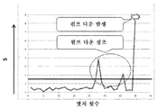
도 11은, 비교예에 관한 펌프 전류의 최댓값을 감시한 경우의 설명도이다. 도 12는, 실시예에 관한 펌프 전류의 최댓값의 표준 편차를 감시한 경우의 설명도이다. 또한, 도 11, 도 12에서의 역치는, 모두 직선(상수)으로 표시하고 있는데, 본 발명을 설명하는데 있어서 정확한 표시를 할 필요가 없기 때문이다. 특히, 도 12의 역치는, 이상이 발생한 프로세스 레시피와 동일한 처리 조건에서 과거에 실행된 프로세스 레시피를 실행한 횟수와 해당 프로세스 레시피 실행마다 산출된 제1 표준 편차(S)로부터 산출된 제2 표준 편차(S)에 상수(이 경우에는 3)를 곱한 값으로 산출된다.11 is an explanatory diagram when the maximum value of the pump current according to the comparative example is monitored. 12 is an explanatory diagram when the standard deviation of the maximum value of the pump current according to the embodiment is monitored. In addition, the threshold values in Figs. 11 and 12 are all displayed in a straight line (constant) because it is not necessary to accurately display the present invention. In particular, the threshold of FIG. 12 is the second standard deviation calculated from the number of times the process recipe executed in the past and the first standard deviation S calculated for each process recipe execution in the same processing conditions as the process recipe in which the abnormality occurred. It is calculated by multiplying (S) by a constant (3 in this case).
본 실시 형태에서, 서브레시피의 스텝 A(지정 스텝)를 복수회 실행하게 된다. 서브레시피 내의 스텝 A의 최댓값으로 관리한 것이 도 11이다. 또한, 도 11에서, 종축은 펌프 전류(Ip)의 값이며, 횡축은 프로세스 레시피의 실행 횟수인 뱃치 횟수이며, 역치를 나타내는 직선은, 예를 들어 펌프의 사양으로 결정되는 펌프 전류의 상한값이다. 이 경우, 서브레시피 내의 스텝의 실행 시간이 짧기 때문에, 펌프 전류(Ip)의 값의 전류 상승이 그 피크까지 달하기 전에, 다음 처리(스텝 B)로 변화해버리기 때문에, 펌프의 전류(Ip)의 최댓값만으로는, 펌프가 정지한 것은 검지할 수 있어도, 펌프의 정지(도 11에서는, 펌프 다운 발생)의 징조를 포착하는 것은 곤란하였다.In this embodiment, step A (designated step) of the sub recipe is executed multiple times. It is FIG. 11 which managed by the maximum value of step A in a sub recipe. In Fig. 11, the vertical axis is the value of the pump current Ip, the horizontal axis is the number of batches which is the number of executions of the process recipe, and the straight line indicating the threshold is, for example, the upper limit value of the pump current determined by the specifications of the pump. In this case, since the execution time of the step in the sub recipe is short, the current of the pump (Ip) is changed because the current rise of the value of the pump current (Ip) reaches the peak before proceeding to the next process (Step B). Even if it was possible to detect that the pump was stopped only with the maximum value of, it was difficult to catch the sign of the stop of the pump (in FIG. 11, the pump down occurred).
한편, 서브레시피의 스텝 A 각각의 펌프 전류(Ip)의 최댓값의 표준 편차(S)를 사용해서 관리한 것이 도 12이다. 또한, 도 12에서, 종축은 펌프 전류(Ip)의 표준 편차(S)이며, 횡축은 프로세스 레시피의 실행 횟수인 뱃치 횟수이며, 역치를 나타내는 직선은, 제2 표준 편차(S)의 3배(3시그마)이다. 이 경우, 스파이크 형상의 전류 상승이 많이 발생하면, 발생 빈도가 많을수록, 반복 n회의 펌프 전류(Ip)의 최댓값의 편차가 커진다. 도 12에서는, 뱃치 횟수 20 내지 25의 사이, 및 뱃치 횟수 30 내지 32의 사이의 2군데에 있어서, 펌프 전류(Ip)의 최댓값의 편차가 크게 되어 있다. 따라서, 발생 빈도를 가미한 검지가 가능하게 되어, 펌프의 정지(도 12에서는, 펌프 다운 발생) 이전에, 펌프의 정지 징조를 포착하는 것이 가능해진다.On the other hand, Fig. 12 shows the management using the standard deviation S of the maximum value of the pump current Ip of each step A of the subrecipe. In Fig. 12, the vertical axis is the standard deviation S of the pump current Ip, the horizontal axis is the number of batches that is the number of executions of the process recipe, and the straight line representing the threshold is 3 times the second standard deviation S ( 3 sigma). In this case, if the spike-shaped current rises a lot, the higher the frequency of occurrence, the larger the deviation of the maximum value of the pump current Ip repeatedly n times. In FIG. 12, the deviation of the maximum value of the pump current Ip is large in two places between 20 to 25 batch times and 30 to 32 batch times. Therefore, it is possible to detect the frequency of occurrence, and it is possible to capture the stop sign of the pump before the pump stops (in FIG. 12, the pump down occurs).
이상, 본 발명자에 의해 이루어진 발명을 실시예에 기초하여 구체적으로 설명했지만, 본 발명은, 상기 실시 형태 및 실시예에 한정되는 것은 아니며, 다양하게 변경 가능한 것은 말할 필요도 없다.As mentioned above, although the invention made by the present inventors has been specifically described based on examples, the present invention is not limited to the above embodiments and examples, and needless to say, various changes are possible.
상술한 실시 형태 및 실시예에서는, 반도체 제조 장치 및 반도체 장치의 제조 방법에 대하여 설명되었지만, 본 발명은 반도체 제조 장치 및 반도체 장치 제조 방법에 한정되는 것은 아니며, 예를 들어 액정 표시(LCD) 장치와 같은 유리 기판을 처리하는 제조 장치 및 그 제조 방법에도 적용 가능하다.In the above-described embodiments and examples, the semiconductor manufacturing apparatus and the manufacturing method of the semiconductor device have been described, but the present invention is not limited to the semiconductor manufacturing apparatus and the semiconductor device manufacturing method, for example, with a liquid crystal display (LCD) device. It is applicable also to the manufacturing apparatus which processes the same glass substrate, and its manufacturing method.
또한, 성막 처리에는, 예를 들어 CVD(chemical vapor deposition), PVD(Physical Vapor Deposition), 산화막, 질화막을 형성하는 처리, 금속을 포함하는 막을 형성하는 처리 등을 포함한다.In addition, the film-forming process includes, for example, chemical vapor deposition (CVD), physical vapor deposition (PVD), oxide film, a process for forming a nitride film, and a process for forming a film containing metal.
또한, 상술한 실시 형태 및 실시예에서는, 성막 처리를 행하는 반도체 제조 장치에 대하여 설명되었지만, 다른 기판 처리 장치(노광 장치, 리소그래피 장치, 도포 장치, 플라스마를 이용한 CVD 장치 등)에도 적용할 수 있다.In addition, although the semiconductor manufacturing apparatus which performs film-forming processing in the above-described embodiments and examples has been described, it can also be applied to other substrate processing apparatuses (exposure apparatus, lithography apparatus, coating apparatus, CVD apparatus using plasma, etc.).
서브레시피를 실행하는 특정 스텝을 포함하는 프로세스 레시피를 컴퓨터에 실행시켜, 피처리체를 처리하는 처리 장치에 적용할 수 있다.A process recipe including a specific step for executing a sub recipe can be executed on a computer and applied to a processing apparatus for processing an object.
1 : 기판 처리 장치
18 : 기판
200 : 제어 시스템
201 : 주컨트롤러
215 : 장치 관리 컨트롤러
215e : 장치 상태 감시부
215f : 이상 해석 지원부
215h : 기억부
DD : 장치 데이터
UCL : 장치 데이터(DD)에 관련된 상한의 지정값, 역치1: Substrate processing device
18: substrate
200: control system
201: Main controller
215: device management controller
215e: device status monitoring unit
215f: abnormal analysis support
215h: memory
DD: device data
UCL: Upper limit designation and threshold related to device data (DD)
Claims (14)
상기 프로세스 레시피의 실행 중인 장치 데이터를 수집하여, 기억부에 축적하는 장치 관리 컨트롤러를 포함하는 기판 처리 장치이며,
상기 장치 관리 컨트롤러는,
상기 장치 데이터가 축적된 상기 기억부를 검색하고,
상기 서브레시피를 구성하는 각 스텝 중 지정 스텝에서의 장치 데이터를, 상기 서브레시피의 실행 횟수분 취득하고,
상기 실행 횟수분 취득된 상기 장치 데이터의 제1 표준 편차를 산출하고,
산출한 상기 제1 표준 편차를 역치와 비교하여, 상기 역치를 초과하면 알람을 발생시키도록 구성되는, 기판 처리 장치.A main controller for executing a process recipe including a specific step for executing a sub recipe, executing the sub recipe for a predetermined number of times in a processing control unit, and performing a predetermined processing on the substrate;
It is a substrate processing apparatus including a device management controller for collecting the device data being executed in the process recipe, and accumulating it in the storage unit,
The device management controller,
Search for the storage unit in which the device data is accumulated,
Of each step constituting the sub-recipe, device data in a designated step is acquired for the number of execution times of the sub-recipe,
Calculate a first standard deviation of the device data acquired for the number of execution times,
And compare the calculated first standard deviation with a threshold value, and generate an alarm when the threshold value is exceeded.
상기 주컨트롤러는, 적어도 상기 제1 스텝 및 상기 제2 스텝을 복수회 실행하면서, 상기 장치 데이터를 상기 장치 관리 컨트롤러에 출력하고,
상기 장치 관리 컨트롤러는, 상기 제1 스텝 및 상기 제2 스텝에서의 상기 장치 데이터를 각각 상기 기억부에 축적하도록 구성되어 있는, 기판 처리 장치.The method of claim 1, wherein the sub-recipe includes at least a first step and a second step,
The main controller outputs the device data to the device management controller while executing at least the first step and the second step multiple times,
The device management controller is configured to store the device data in the first step and the second step, respectively, in the storage unit.
상기 제2 스텝은 반응 가스를 상기 처리실에 공급하는 스텝이며,
상기 서브레시피는 또한, 상기 원료 가스를 퍼지하는 제3 스텝 또는 상기 반응 가스를 퍼지하는 제4 스텝을 포함하도록 구성되어 있는, 기판 처리 장치.The method of claim 7, wherein the first step is a step of supplying a raw material gas to the processing chamber,
The second step is a step of supplying a reaction gas to the processing chamber,
The sub-recipe further comprises a third step of purging the raw material gas or a fourth step of purging the reaction gas.
상기 비교부는, 상기 제1 표준 편차가 상기 역치를 초과하고 있으면 상기 이상 해석 지원부에 이상을 통지하고,
상기 이상 해석 지원부는, 상기 이상의 요인을 해석하기 위한 장해 정보 화면을 조작 화면에 표시시키도록 구성되어 있는, 기판 처리 장치.The apparatus of claim 9, further comprising an anomaly analysis support unit configured to support an anomaly analysis occurring in the apparatus,
The comparison unit notifies the abnormality analysis support unit of the abnormality when the first standard deviation exceeds the threshold,
The abnormality analysis support unit is configured to display a failure information screen for analyzing the abnormality factor on an operation screen.
상기 장치 데이터가 축적된 상기 기억부를 검색하는 공정과,
상기 서브레시피 중 지정 스텝에서의 상기 장치 데이터를, 상기 서브레시피의 실행 횟수분 취득하는 공정과,
상기 실행 횟수분 취득된 상기 장치 데이터의 제1 표준 편차를 산출하는 공정과,
산출한 상기 제1 표준 편차를 역치와 비교하는 공정과,
상기 역치를 초과하면 알람을 발생시키는 공정을 갖는,
기판 처리 장치의 이상 감시 방법.When executing a process recipe including a specific step for executing a sub-recipe, the sub-recipe is executed by a processing control unit, and an operation unit for controlling to perform a predetermined process on the substrate, and running device data of the process recipe are collected. , It is an abnormality monitoring method of the substrate processing apparatus including the data monitoring unit which accumulates in the storage unit
Searching for the storage unit in which the device data is accumulated;
A step of acquiring the device data in a designated step among the sub-recipients for the number of execution times of the sub-recipe;
Calculating a first standard deviation of the device data acquired for the number of execution times;
Comparing the calculated first standard deviation with a threshold,
Having a process for generating an alarm when the threshold is exceeded,
Method for abnormality monitoring of substrate processing equipment.
상기 프로세스 레시피의 실행 중인 장치 데이터를 수집하여, 기억부에 축적하는 장치 관리 컨트롤러
를 포함하는 기판 처리 장치를 제어하기 위한 컴퓨터에서 실행되는 기판 처리 장치의 프로그램이며,
상기 장치 데이터가 축적된 상기 기억부를 검색하는 수순과,
상기 서브레시피를 구성하는 각 스텝 중 지정 스텝에서의 상기 장치 데이터를, 상기 서브레시피의 실행 횟수분 취득하는 수순과,
상기 실행 횟수분 취득된 상기 장치 데이터의 제1 표준 편차를 산출하는 수순과,
산출한 상기 제1 표준 편차를 역치와 비교하여, 상기 역치를 초과하면 알람을 발생시키는 수순
을 컴퓨터에 실행시키는 프로그램.A main controller for executing a process recipe including a specific step for executing a sub recipe, executing the sub recipe for a predetermined number of times in a processing control unit, and performing a predetermined processing on the substrate;
A device management controller that collects running device data of the process recipe and stores it in a storage unit
It is a program of a substrate processing apparatus executed in a computer for controlling a substrate processing apparatus comprising a,
A procedure for searching the storage unit in which the device data is accumulated;
A procedure for acquiring the device data at a designated step among the steps constituting the subrecipe for the number of execution times of the subrecipe;
A procedure for calculating a first standard deviation of the device data acquired for the number of execution times;
The procedure of comparing the calculated first standard deviation with a threshold and generating an alarm when the threshold is exceeded
A program that runs the computer.
Priority Applications (1)
| Application Number | Priority Date | Filing Date | Title |
|---|---|---|---|
| KR1020227013031A KR102519802B1 (en) | 2017-09-04 | 2017-09-04 | Substrate processing device, method for monitoring for anomaly in substrate processing device, and program stored in recording medium |
Applications Claiming Priority (1)
| Application Number | Priority Date | Filing Date | Title |
|---|---|---|---|
| PCT/JP2017/031719 WO2019043934A1 (en) | 2017-09-04 | 2017-09-04 | Substrate processing device, method for monitoring for anomaly in substrate processing device, and program |
Related Child Applications (1)
| Application Number | Title | Priority Date | Filing Date |
|---|---|---|---|
| KR1020227013031A Division KR102519802B1 (en) | 2017-09-04 | 2017-09-04 | Substrate processing device, method for monitoring for anomaly in substrate processing device, and program stored in recording medium |
Publications (2)
| Publication Number | Publication Date |
|---|---|
| KR20200029598A true KR20200029598A (en) | 2020-03-18 |
| KR102389689B1 KR102389689B1 (en) | 2022-04-22 |
Family
ID=65527238
Family Applications (2)
| Application Number | Title | Priority Date | Filing Date |
|---|---|---|---|
| KR1020227013031A KR102519802B1 (en) | 2017-09-04 | 2017-09-04 | Substrate processing device, method for monitoring for anomaly in substrate processing device, and program stored in recording medium |
| KR1020207006145A KR102389689B1 (en) | 2017-09-04 | 2017-09-04 | Substrate processing apparatus, abnormal monitoring method of substrate processing apparatus, and program stored in recording medium |
Family Applications Before (1)
| Application Number | Title | Priority Date | Filing Date |
|---|---|---|---|
| KR1020227013031A KR102519802B1 (en) | 2017-09-04 | 2017-09-04 | Substrate processing device, method for monitoring for anomaly in substrate processing device, and program stored in recording medium |
Country Status (5)
| Country | Link |
|---|---|
| US (1) | US11782425B2 (en) |
| JP (1) | JP6833048B2 (en) |
| KR (2) | KR102519802B1 (en) |
| SG (1) | SG11202001932UA (en) |
| WO (1) | WO2019043934A1 (en) |
Families Citing this family (4)
| Publication number | Priority date | Publication date | Assignee | Title |
|---|---|---|---|---|
| JP7304692B2 (en) * | 2018-12-13 | 2023-07-07 | 東京エレクトロン株式会社 | Substrate processing method and substrate processing apparatus |
| JP7188560B2 (en) * | 2019-03-27 | 2022-12-13 | 株式会社島津製作所 | Data processing program for pump monitor, vacuum pump and product deposition diagnostics |
| KR102073789B1 (en) * | 2019-07-05 | 2020-02-05 | 김태화 | Pump back stream preventing structure for semiconductor manufacturing device |
| JP7246576B2 (en) * | 2020-07-02 | 2023-03-27 | 東京エレクトロン株式会社 | Information processing method, model generation method, and information processing device |
Citations (7)
| Publication number | Priority date | Publication date | Assignee | Title |
|---|---|---|---|---|
| JPS5855841B2 (en) | 1978-06-19 | 1983-12-12 | チエルヤビンスキ− ポリテクニチエスキ− インスチテユ−ト イメニ レニンスコゴ コムソモラ | Metal bar rolling method and rolling roll for it |
| KR19990071784A (en) * | 1995-12-04 | 1999-09-27 | 미키오 이시마루 | Monitoring and analysis system for manufacturing processes using single-step feedback and statistical simulation |
| JP2000283056A (en) * | 1999-03-26 | 2000-10-10 | Hitachi Ltd | Vacuum pump abnormality monitoring system |
| KR20090043511A (en) * | 2006-08-01 | 2009-05-06 | 도쿄엘렉트론가부시키가이샤 | Server device and program |
| JP2012186213A (en) | 2011-03-03 | 2012-09-27 | Hitachi Kokusai Electric Inc | Substrate processing system, management apparatus and data analysis method |
| JP2016134585A (en) * | 2015-01-22 | 2016-07-25 | ルネサスエレクトロニクス株式会社 | Semiconductor manufacturing device, diagnosis system for the same, and method of manufacturing semiconductor device |
| JP2017011051A (en) * | 2015-06-19 | 2017-01-12 | 株式会社ジェイ・イー・ティ | Substrate processing system and substrate processing method |
Family Cites Families (11)
| Publication number | Priority date | Publication date | Assignee | Title |
|---|---|---|---|---|
| US7477960B2 (en) * | 2005-02-16 | 2009-01-13 | Tokyo Electron Limited | Fault detection and classification (FDC) using a run-to-run controller |
| JP4712462B2 (en) * | 2005-07-11 | 2011-06-29 | 東京エレクトロン株式会社 | Substrate processing monitoring device, substrate processing monitoring system, substrate processing monitoring program, and recording medium |
| JP5015015B2 (en) * | 2006-01-27 | 2012-08-29 | 株式会社日立国際電気 | Substrate processing apparatus, recipe display method, substrate processing method, semiconductor device manufacturing method, and recipe transition display method |
| CN101359965B (en) * | 2008-09-18 | 2011-04-20 | 中兴通讯股份有限公司 | Method and apparatus optimizing determination level of optical receiver |
| US8618807B2 (en) * | 2009-06-30 | 2013-12-31 | Lam Research Corporation | Arrangement for identifying uncontrolled events at the process module level and methods thereof |
| JP5490462B2 (en) * | 2009-08-17 | 2014-05-14 | 横河電機株式会社 | Film thickness measuring device |
| JP5855841B2 (en) * | 2011-04-01 | 2016-02-09 | 株式会社日立国際電気 | Management device |
| US9255578B2 (en) * | 2012-07-31 | 2016-02-09 | Fisher-Rosemount Systems, Inc. | Systems and methods to monitor pump cavitation |
| US10724137B2 (en) * | 2013-02-05 | 2020-07-28 | Kokusai Eletric Corporation | Cleaning method, method of manufacturing semiconductor device, substrate processing apparatus, recording medium, and cleaning completion determining method |
| JP2015115540A (en) * | 2013-12-13 | 2015-06-22 | 株式会社日立国際電気 | Management apparatus, management method of substrate processing device, substrate processing system and recording medium |
| JP6723669B2 (en) * | 2016-09-27 | 2020-07-15 | 東京エレクトロン株式会社 | Abnormality detection program, abnormality detection method, and abnormality detection device |
-
2017
- 2017-09-04 WO PCT/JP2017/031719 patent/WO2019043934A1/en active Application Filing
- 2017-09-04 SG SG11202001932UA patent/SG11202001932UA/en unknown
- 2017-09-04 KR KR1020227013031A patent/KR102519802B1/en active IP Right Grant
- 2017-09-04 JP JP2019538899A patent/JP6833048B2/en active Active
- 2017-09-04 KR KR1020207006145A patent/KR102389689B1/en active IP Right Grant
-
2020
- 2020-03-03 US US16/807,601 patent/US11782425B2/en active Active
Patent Citations (7)
| Publication number | Priority date | Publication date | Assignee | Title |
|---|---|---|---|---|
| JPS5855841B2 (en) | 1978-06-19 | 1983-12-12 | チエルヤビンスキ− ポリテクニチエスキ− インスチテユ−ト イメニ レニンスコゴ コムソモラ | Metal bar rolling method and rolling roll for it |
| KR19990071784A (en) * | 1995-12-04 | 1999-09-27 | 미키오 이시마루 | Monitoring and analysis system for manufacturing processes using single-step feedback and statistical simulation |
| JP2000283056A (en) * | 1999-03-26 | 2000-10-10 | Hitachi Ltd | Vacuum pump abnormality monitoring system |
| KR20090043511A (en) * | 2006-08-01 | 2009-05-06 | 도쿄엘렉트론가부시키가이샤 | Server device and program |
| JP2012186213A (en) | 2011-03-03 | 2012-09-27 | Hitachi Kokusai Electric Inc | Substrate processing system, management apparatus and data analysis method |
| JP2016134585A (en) * | 2015-01-22 | 2016-07-25 | ルネサスエレクトロニクス株式会社 | Semiconductor manufacturing device, diagnosis system for the same, and method of manufacturing semiconductor device |
| JP2017011051A (en) * | 2015-06-19 | 2017-01-12 | 株式会社ジェイ・イー・ティ | Substrate processing system and substrate processing method |
Also Published As
| Publication number | Publication date |
|---|---|
| SG11202001932UA (en) | 2020-04-29 |
| JPWO2019043934A1 (en) | 2020-03-26 |
| KR102389689B1 (en) | 2022-04-22 |
| US11782425B2 (en) | 2023-10-10 |
| US20200201305A1 (en) | 2020-06-25 |
| JP6833048B2 (en) | 2021-02-24 |
| WO2019043934A1 (en) | 2019-03-07 |
| KR102519802B1 (en) | 2023-04-10 |
| KR20220051437A (en) | 2022-04-26 |
Similar Documents
| Publication | Publication Date | Title |
|---|---|---|
| KR102089890B1 (en) | Substrate processing apparatus, device management controller, and program | |
| US11782425B2 (en) | Substrate processing apparatus, method of monitoring abnormality of substrate processing apparatus, and recording medium | |
| KR102192094B1 (en) | Substrate processing unit, device management controller and recording medium | |
| KR102243476B1 (en) | Substrate processing apparatus, apparatus management controller, program and method of manufacturing semiconductor device | |
| CN107240564B (en) | Processing device, device management controller, and device management method | |
| US20220375331A1 (en) | Processing Apparatus, Display Method, Method of Manufacturing Semiconductor Device and Non-transitory Computer-readable Recording Medium | |
| CN107305855B (en) | Substrate processing apparatus, apparatus management controller and apparatus management method | |
| KR20210019057A (en) | Substrate processing apparatus, manufacturing method and program of semiconductor device |
Legal Events
| Date | Code | Title | Description |
|---|---|---|---|
| E902 | Notification of reason for refusal | ||
| E701 | Decision to grant or registration of patent right | ||
| A107 | Divisional application of patent | ||
| GRNT | Written decision to grant |