KR20200029521A - Carbon catalyst, battery electrode and battery - Google Patents
Carbon catalyst, battery electrode and battery Download PDFInfo
- Publication number
- KR20200029521A KR20200029521A KR1020207003951A KR20207003951A KR20200029521A KR 20200029521 A KR20200029521 A KR 20200029521A KR 1020207003951 A KR1020207003951 A KR 1020207003951A KR 20207003951 A KR20207003951 A KR 20207003951A KR 20200029521 A KR20200029521 A KR 20200029521A
- Authority
- KR
- South Korea
- Prior art keywords
- catalyst
- carbon
- carbon catalyst
- present
- ratio
- Prior art date
Links
- 239000003054 catalyst Substances 0.000 title claims abstract description 309
- OKTJSMMVPCPJKN-UHFFFAOYSA-N Carbon Chemical compound [C] OKTJSMMVPCPJKN-UHFFFAOYSA-N 0.000 title claims abstract description 191
- 229910052799 carbon Inorganic materials 0.000 title claims abstract description 183
- XEEYBQQBJWHFJM-UHFFFAOYSA-N Iron Chemical compound [Fe] XEEYBQQBJWHFJM-UHFFFAOYSA-N 0.000 claims abstract description 141
- 229910052742 iron Inorganic materials 0.000 claims abstract description 78
- 238000002835 absorbance Methods 0.000 claims abstract description 28
- 238000010521 absorption reaction Methods 0.000 claims abstract description 25
- 239000012299 nitrogen atmosphere Substances 0.000 claims abstract description 12
- 238000002411 thermogravimetry Methods 0.000 claims abstract description 7
- 229910052751 metal Inorganic materials 0.000 claims description 70
- 239000002184 metal Substances 0.000 claims description 70
- 229910052757 nitrogen Inorganic materials 0.000 claims description 48
- 125000004433 nitrogen atom Chemical group N* 0.000 claims description 42
- 238000000921 elemental analysis Methods 0.000 claims description 32
- 238000004458 analytical method Methods 0.000 claims description 19
- 230000004580 weight loss Effects 0.000 claims description 16
- 150000001721 carbon Chemical group 0.000 claims description 13
- 238000001095 inductively coupled plasma mass spectrometry Methods 0.000 claims description 12
- 238000009841 combustion method Methods 0.000 claims description 11
- 239000011148 porous material Substances 0.000 claims description 8
- 238000004438 BET method Methods 0.000 claims description 5
- 230000003197 catalytic effect Effects 0.000 abstract description 29
- 239000013585 weight reducing agent Substances 0.000 abstract description 8
- 238000012916 structural analysis Methods 0.000 abstract 1
- 230000000052 comparative effect Effects 0.000 description 57
- 238000012360 testing method Methods 0.000 description 46
- PXHVJJICTQNCMI-UHFFFAOYSA-N Nickel Chemical compound [Ni] PXHVJJICTQNCMI-UHFFFAOYSA-N 0.000 description 44
- 239000002994 raw material Substances 0.000 description 38
- 239000000203 mixture Substances 0.000 description 37
- BASFCYQUMIYNBI-UHFFFAOYSA-N platinum Chemical compound [Pt] BASFCYQUMIYNBI-UHFFFAOYSA-N 0.000 description 37
- 229910052725 zinc Inorganic materials 0.000 description 32
- 239000011701 zinc Substances 0.000 description 32
- 238000003763 carbonization Methods 0.000 description 29
- CWYNVVGOOAEACU-UHFFFAOYSA-N Fe2+ Chemical compound [Fe+2] CWYNVVGOOAEACU-UHFFFAOYSA-N 0.000 description 28
- 239000010410 layer Substances 0.000 description 28
- 238000004833 X-ray photoelectron spectroscopy Methods 0.000 description 25
- 229910052759 nickel Inorganic materials 0.000 description 25
- 238000000833 X-ray absorption fine structure spectroscopy Methods 0.000 description 24
- IJGRMHOSHXDMSA-UHFFFAOYSA-N Atomic nitrogen Chemical compound N#N IJGRMHOSHXDMSA-UHFFFAOYSA-N 0.000 description 21
- 229910052782 aluminium Inorganic materials 0.000 description 21
- XAGFODPZIPBFFR-UHFFFAOYSA-N aluminium Chemical compound [Al] XAGFODPZIPBFFR-UHFFFAOYSA-N 0.000 description 21
- -1 ferrous transition metal Chemical class 0.000 description 21
- HCHKCACWOHOZIP-UHFFFAOYSA-N Zinc Chemical compound [Zn] HCHKCACWOHOZIP-UHFFFAOYSA-N 0.000 description 20
- 239000005539 carbonized material Substances 0.000 description 19
- 229910052723 transition metal Inorganic materials 0.000 description 16
- 239000000126 substance Substances 0.000 description 15
- KDLHZDBZIXYQEI-UHFFFAOYSA-N Palladium Chemical compound [Pd] KDLHZDBZIXYQEI-UHFFFAOYSA-N 0.000 description 14
- 239000000446 fuel Substances 0.000 description 14
- 239000011651 chromium Substances 0.000 description 13
- 239000010936 titanium Substances 0.000 description 13
- 229910052688 Gadolinium Inorganic materials 0.000 description 12
- 229910052779 Neodymium Inorganic materials 0.000 description 12
- 229910052772 Samarium Inorganic materials 0.000 description 12
- 229910052804 chromium Inorganic materials 0.000 description 12
- 229910052697 platinum Inorganic materials 0.000 description 12
- 229910052719 titanium Inorganic materials 0.000 description 12
- FYYHWMGAXLPEAU-UHFFFAOYSA-N Magnesium Chemical compound [Mg] FYYHWMGAXLPEAU-UHFFFAOYSA-N 0.000 description 11
- 239000011777 magnesium Substances 0.000 description 11
- 229910052749 magnesium Inorganic materials 0.000 description 11
- 239000002245 particle Substances 0.000 description 11
- 239000010948 rhodium Substances 0.000 description 10
- 150000003624 transition metals Chemical class 0.000 description 10
- XLYOFNOQVPJJNP-UHFFFAOYSA-N water Substances O XLYOFNOQVPJJNP-UHFFFAOYSA-N 0.000 description 10
- RYGMFSIKBFXOCR-UHFFFAOYSA-N Copper Chemical compound [Cu] RYGMFSIKBFXOCR-UHFFFAOYSA-N 0.000 description 9
- QVGXLLKOCUKJST-UHFFFAOYSA-N atomic oxygen Chemical compound [O] QVGXLLKOCUKJST-UHFFFAOYSA-N 0.000 description 9
- 239000010949 copper Substances 0.000 description 9
- 238000004502 linear sweep voltammetry Methods 0.000 description 9
- 230000014759 maintenance of location Effects 0.000 description 9
- 239000011572 manganese Substances 0.000 description 9
- 239000010955 niobium Substances 0.000 description 9
- 229910052760 oxygen Inorganic materials 0.000 description 9
- 239000001301 oxygen Substances 0.000 description 9
- 238000010248 power generation Methods 0.000 description 9
- 230000009467 reduction Effects 0.000 description 9
- 239000002344 surface layer Substances 0.000 description 9
- 229910052802 copper Inorganic materials 0.000 description 8
- 239000011889 copper foil Substances 0.000 description 8
- 238000009792 diffusion process Methods 0.000 description 8
- 239000007789 gas Substances 0.000 description 8
- 229910052747 lanthanoid Inorganic materials 0.000 description 8
- 150000002602 lanthanoids Chemical class 0.000 description 8
- 229910052748 manganese Inorganic materials 0.000 description 8
- 238000000034 method Methods 0.000 description 8
- 229910052750 molybdenum Inorganic materials 0.000 description 8
- 229910052758 niobium Inorganic materials 0.000 description 8
- 239000011368 organic material Substances 0.000 description 8
- 229910052706 scandium Inorganic materials 0.000 description 8
- 229910052709 silver Inorganic materials 0.000 description 8
- 229910052727 yttrium Inorganic materials 0.000 description 8
- 229910052768 actinide Inorganic materials 0.000 description 7
- 150000001255 actinides Chemical class 0.000 description 7
- 239000012298 atmosphere Substances 0.000 description 7
- 239000001257 hydrogen Substances 0.000 description 7
- 229910052739 hydrogen Inorganic materials 0.000 description 7
- 229910052763 palladium Inorganic materials 0.000 description 7
- 229910052703 rhodium Inorganic materials 0.000 description 7
- 229910052707 ruthenium Inorganic materials 0.000 description 7
- 229910052720 vanadium Inorganic materials 0.000 description 7
- 229910052726 zirconium Inorganic materials 0.000 description 7
- UFHFLCQGNIYNRP-UHFFFAOYSA-N Hydrogen Chemical compound [H][H] UFHFLCQGNIYNRP-UHFFFAOYSA-N 0.000 description 6
- ZMXDDKWLCZADIW-UHFFFAOYSA-N N,N-Dimethylformamide Chemical compound CN(C)C=O ZMXDDKWLCZADIW-UHFFFAOYSA-N 0.000 description 6
- 238000010586 diagram Methods 0.000 description 6
- 239000008151 electrolyte solution Substances 0.000 description 6
- 239000010931 gold Substances 0.000 description 6
- 229910052736 halogen Inorganic materials 0.000 description 6
- 238000004519 manufacturing process Methods 0.000 description 6
- 239000002002 slurry Substances 0.000 description 6
- 238000001179 sorption measurement Methods 0.000 description 6
- 239000001913 cellulose Substances 0.000 description 5
- 229920002678 cellulose Polymers 0.000 description 5
- 230000000694 effects Effects 0.000 description 5
- 230000001747 exhibiting effect Effects 0.000 description 5
- 238000010438 heat treatment Methods 0.000 description 5
- 230000000737 periodic effect Effects 0.000 description 5
- 229920002239 polyacrylonitrile Polymers 0.000 description 5
- 229920006395 saturated elastomer Polymers 0.000 description 5
- 239000000243 solution Substances 0.000 description 5
- LXBGSDVWAMZHDD-UHFFFAOYSA-N 2-methyl-1h-imidazole Chemical compound CC1=NC=CN1 LXBGSDVWAMZHDD-UHFFFAOYSA-N 0.000 description 4
- VEXZGXHMUGYJMC-UHFFFAOYSA-N Hydrochloric acid Chemical compound Cl VEXZGXHMUGYJMC-UHFFFAOYSA-N 0.000 description 4
- 229920000557 Nafion® Polymers 0.000 description 4
- 229920002845 Poly(methacrylic acid) Polymers 0.000 description 4
- 229920002125 Sokalan® Polymers 0.000 description 4
- 239000006229 carbon black Substances 0.000 description 4
- 239000003575 carbonaceous material Substances 0.000 description 4
- 239000012153 distilled water Substances 0.000 description 4
- 238000001035 drying Methods 0.000 description 4
- 229910052737 gold Inorganic materials 0.000 description 4
- 125000005843 halogen group Chemical group 0.000 description 4
- 238000005259 measurement Methods 0.000 description 4
- 239000012528 membrane Substances 0.000 description 4
- QJGQUHMNIGDVPM-UHFFFAOYSA-N nitrogen group Chemical group [N] QJGQUHMNIGDVPM-UHFFFAOYSA-N 0.000 description 4
- 238000010606 normalization Methods 0.000 description 4
- 239000004584 polyacrylic acid Substances 0.000 description 4
- 239000000047 product Substances 0.000 description 4
- 239000007787 solid Substances 0.000 description 4
- JIAARYAFYJHUJI-UHFFFAOYSA-L zinc dichloride Chemical compound [Cl-].[Cl-].[Zn+2] JIAARYAFYJHUJI-UHFFFAOYSA-L 0.000 description 4
- KFZMGEQAYNKOFK-UHFFFAOYSA-N Isopropanol Chemical compound CC(C)O KFZMGEQAYNKOFK-UHFFFAOYSA-N 0.000 description 3
- KWYUFKZDYYNOTN-UHFFFAOYSA-M Potassium hydroxide Chemical compound [OH-].[K+] KWYUFKZDYYNOTN-UHFFFAOYSA-M 0.000 description 3
- KJTLSVCANCCWHF-UHFFFAOYSA-N Ruthenium Chemical compound [Ru] KJTLSVCANCCWHF-UHFFFAOYSA-N 0.000 description 3
- 239000002253 acid Substances 0.000 description 3
- JZQOJFLIJNRDHK-CMDGGOBGSA-N alpha-irone Chemical compound CC1CC=C(C)C(\C=C\C(C)=O)C1(C)C JZQOJFLIJNRDHK-CMDGGOBGSA-N 0.000 description 3
- 239000007864 aqueous solution Substances 0.000 description 3
- 238000010000 carbonizing Methods 0.000 description 3
- 239000011248 coating agent Substances 0.000 description 3
- 238000000576 coating method Methods 0.000 description 3
- 229920001577 copolymer Polymers 0.000 description 3
- 238000005520 cutting process Methods 0.000 description 3
- 229910001873 dinitrogen Inorganic materials 0.000 description 3
- RAXXELZNTBOGNW-UHFFFAOYSA-N imidazole Natural products C1=CNC=N1 RAXXELZNTBOGNW-UHFFFAOYSA-N 0.000 description 3
- 229910052741 iridium Inorganic materials 0.000 description 3
- NQXWGWZJXJUMQB-UHFFFAOYSA-K iron trichloride hexahydrate Chemical compound O.O.O.O.O.O.[Cl-].Cl[Fe+]Cl NQXWGWZJXJUMQB-UHFFFAOYSA-K 0.000 description 3
- 238000002156 mixing Methods 0.000 description 3
- 150000002894 organic compounds Chemical class 0.000 description 3
- 229910052762 osmium Inorganic materials 0.000 description 3
- 125000004430 oxygen atom Chemical group O* 0.000 description 3
- 238000002186 photoelectron spectrum Methods 0.000 description 3
- 229920000642 polymer Polymers 0.000 description 3
- 230000001603 reducing effect Effects 0.000 description 3
- 229920005989 resin Polymers 0.000 description 3
- 239000011347 resin Substances 0.000 description 3
- 230000002441 reversible effect Effects 0.000 description 3
- MHOVAHRLVXNVSD-UHFFFAOYSA-N rhodium atom Chemical compound [Rh] MHOVAHRLVXNVSD-UHFFFAOYSA-N 0.000 description 3
- 239000010944 silver (metal) Substances 0.000 description 3
- 238000001228 spectrum Methods 0.000 description 3
- 238000003756 stirring Methods 0.000 description 3
- 238000001075 voltammogram Methods 0.000 description 3
- 238000003466 welding Methods 0.000 description 3
- 229910000859 α-Fe Inorganic materials 0.000 description 3
- NWUYHJFMYQTDRP-UHFFFAOYSA-N 1,2-bis(ethenyl)benzene;1-ethenyl-2-ethylbenzene;styrene Chemical compound C=CC1=CC=CC=C1.CCC1=CC=CC=C1C=C.C=CC1=CC=CC=C1C=C NWUYHJFMYQTDRP-UHFFFAOYSA-N 0.000 description 2
- VEUMANXWQDHAJV-UHFFFAOYSA-N 2-[2-[(2-hydroxyphenyl)methylideneamino]ethyliminomethyl]phenol Chemical compound OC1=CC=CC=C1C=NCCN=CC1=CC=CC=C1O VEUMANXWQDHAJV-UHFFFAOYSA-N 0.000 description 2
- PAYRUJLWNCNPSJ-UHFFFAOYSA-N Aniline Chemical compound NC1=CC=CC=C1 PAYRUJLWNCNPSJ-UHFFFAOYSA-N 0.000 description 2
- LFQSCWFLJHTTHZ-UHFFFAOYSA-N Ethanol Chemical compound CCO LFQSCWFLJHTTHZ-UHFFFAOYSA-N 0.000 description 2
- YLQBMQCUIZJEEH-UHFFFAOYSA-N Furan Chemical compound C=1C=COC=1 YLQBMQCUIZJEEH-UHFFFAOYSA-N 0.000 description 2
- OAKJQQAXSVQMHS-UHFFFAOYSA-N Hydrazine Chemical compound NN OAKJQQAXSVQMHS-UHFFFAOYSA-N 0.000 description 2
- UQSXHKLRYXJYBZ-UHFFFAOYSA-N Iron oxide Chemical compound [Fe]=O UQSXHKLRYXJYBZ-UHFFFAOYSA-N 0.000 description 2
- 229920000877 Melamine resin Polymers 0.000 description 2
- 229910000861 Mg alloy Inorganic materials 0.000 description 2
- YNAVUWVOSKDBBP-UHFFFAOYSA-N Morpholine Chemical compound C1COCCN1 YNAVUWVOSKDBBP-UHFFFAOYSA-N 0.000 description 2
- GLUUGHFHXGJENI-UHFFFAOYSA-N Piperazine Chemical compound C1CNCCN1 GLUUGHFHXGJENI-UHFFFAOYSA-N 0.000 description 2
- KAESVJOAVNADME-UHFFFAOYSA-N Pyrrole Chemical compound C=1C=CNC=1 KAESVJOAVNADME-UHFFFAOYSA-N 0.000 description 2
- FAPWRFPIFSIZLT-UHFFFAOYSA-M Sodium chloride Chemical compound [Na+].[Cl-] FAPWRFPIFSIZLT-UHFFFAOYSA-M 0.000 description 2
- YTPLMLYBLZKORZ-UHFFFAOYSA-N Thiophene Chemical compound C=1C=CSC=1 YTPLMLYBLZKORZ-UHFFFAOYSA-N 0.000 description 2
- 125000004429 atom Chemical group 0.000 description 2
- 230000005587 bubbling Effects 0.000 description 2
- 230000008859 change Effects 0.000 description 2
- 150000001875 compounds Chemical class 0.000 description 2
- 238000001514 detection method Methods 0.000 description 2
- 238000009826 distribution Methods 0.000 description 2
- 239000011363 dried mixture Substances 0.000 description 2
- 150000002148 esters Chemical class 0.000 description 2
- 238000011156 evaluation Methods 0.000 description 2
- 239000000706 filtrate Substances 0.000 description 2
- 238000001914 filtration Methods 0.000 description 2
- 230000004927 fusion Effects 0.000 description 2
- PCHJSUWPFVWCPO-UHFFFAOYSA-N gold Chemical compound [Au] PCHJSUWPFVWCPO-UHFFFAOYSA-N 0.000 description 2
- 238000000227 grinding Methods 0.000 description 2
- 150000002367 halogens Chemical class 0.000 description 2
- 125000004435 hydrogen atom Chemical group [H]* 0.000 description 2
- 238000009616 inductively coupled plasma Methods 0.000 description 2
- 239000011261 inert gas Substances 0.000 description 2
- GKOZUEZYRPOHIO-UHFFFAOYSA-N iridium atom Chemical compound [Ir] GKOZUEZYRPOHIO-UHFFFAOYSA-N 0.000 description 2
- 230000007935 neutral effect Effects 0.000 description 2
- 229910052755 nonmetal Inorganic materials 0.000 description 2
- SYQBFIAQOQZEGI-UHFFFAOYSA-N osmium atom Chemical compound [Os] SYQBFIAQOQZEGI-UHFFFAOYSA-N 0.000 description 2
- VLTRZXGMWDSKGL-UHFFFAOYSA-N perchloric acid Chemical compound OCl(=O)(=O)=O VLTRZXGMWDSKGL-UHFFFAOYSA-N 0.000 description 2
- 238000005554 pickling Methods 0.000 description 2
- 239000005518 polymer electrolyte Substances 0.000 description 2
- 238000010298 pulverizing process Methods 0.000 description 2
- XSCHRSMBECNVNS-UHFFFAOYSA-N quinoxaline Chemical compound N1=CC=NC2=CC=CC=C21 XSCHRSMBECNVNS-UHFFFAOYSA-N 0.000 description 2
- 239000002904 solvent Substances 0.000 description 2
- 238000002798 spectrophotometry method Methods 0.000 description 2
- 239000000758 substrate Substances 0.000 description 2
- KDYFGRWQOYBRFD-UHFFFAOYSA-N succinic acid Chemical compound OC(=O)CCC(O)=O KDYFGRWQOYBRFD-UHFFFAOYSA-N 0.000 description 2
- 239000000725 suspension Substances 0.000 description 2
- 239000011592 zinc chloride Substances 0.000 description 2
- 235000005074 zinc chloride Nutrition 0.000 description 2
- MGRVRXRGTBOSHW-UHFFFAOYSA-N (aminomethyl)phosphonic acid Chemical compound NCP(O)(O)=O MGRVRXRGTBOSHW-UHFFFAOYSA-N 0.000 description 1
- JYEUMXHLPRZUAT-UHFFFAOYSA-N 1,2,3-triazine Chemical compound C1=CN=NN=C1 JYEUMXHLPRZUAT-UHFFFAOYSA-N 0.000 description 1
- MCTWTZJPVLRJOU-UHFFFAOYSA-N 1-methyl-1H-imidazole Chemical compound CN1C=CN=C1 MCTWTZJPVLRJOU-UHFFFAOYSA-N 0.000 description 1
- HYZJCKYKOHLVJF-UHFFFAOYSA-N 1H-benzimidazole Chemical compound C1=CC=C2NC=NC2=C1 HYZJCKYKOHLVJF-UHFFFAOYSA-N 0.000 description 1
- RNAMYOYQYRYFQY-UHFFFAOYSA-N 2-(4,4-difluoropiperidin-1-yl)-6-methoxy-n-(1-propan-2-ylpiperidin-4-yl)-7-(3-pyrrolidin-1-ylpropoxy)quinazolin-4-amine Chemical compound N1=C(N2CCC(F)(F)CC2)N=C2C=C(OCCCN3CCCC3)C(OC)=CC2=C1NC1CCN(C(C)C)CC1 RNAMYOYQYRYFQY-UHFFFAOYSA-N 0.000 description 1
- KXGFMDJXCMQABM-UHFFFAOYSA-N 2-methoxy-6-methylphenol Chemical compound [CH]OC1=CC=CC([CH])=C1O KXGFMDJXCMQABM-UHFFFAOYSA-N 0.000 description 1
- KGIGUEBEKRSTEW-UHFFFAOYSA-N 2-vinylpyridine Chemical compound C=CC1=CC=CC=N1 KGIGUEBEKRSTEW-UHFFFAOYSA-N 0.000 description 1
- MGADZUXDNSDTHW-UHFFFAOYSA-N 2H-pyran Chemical compound C1OC=CC=C1 MGADZUXDNSDTHW-UHFFFAOYSA-N 0.000 description 1
- LOXWVAXWPZWIOO-UHFFFAOYSA-N 7-bromo-1-chloronaphthalene Chemical compound C1=C(Br)C=C2C(Cl)=CC=CC2=C1 LOXWVAXWPZWIOO-UHFFFAOYSA-N 0.000 description 1
- NLHHRLWOUZZQLW-UHFFFAOYSA-N Acrylonitrile Chemical compound C=CC#N NLHHRLWOUZZQLW-UHFFFAOYSA-N 0.000 description 1
- 239000002028 Biomass Substances 0.000 description 1
- PZNSFCLAULLKQX-UHFFFAOYSA-N Boron nitride Chemical compound N#B PZNSFCLAULLKQX-UHFFFAOYSA-N 0.000 description 1
- UJOBWOGCFQCDNV-UHFFFAOYSA-N Carbazole Natural products C1=CC=C2C3=CC=CC=C3NC2=C1 UJOBWOGCFQCDNV-UHFFFAOYSA-N 0.000 description 1
- 229920002134 Carboxymethyl cellulose Polymers 0.000 description 1
- 229920002101 Chitin Polymers 0.000 description 1
- 229920001661 Chitosan Polymers 0.000 description 1
- VYZAMTAEIAYCRO-UHFFFAOYSA-N Chromium Chemical compound [Cr] VYZAMTAEIAYCRO-UHFFFAOYSA-N 0.000 description 1
- MBMLMWLHJBBADN-UHFFFAOYSA-N Ferrous sulfide Chemical compound [Fe]=S MBMLMWLHJBBADN-UHFFFAOYSA-N 0.000 description 1
- 229910002617 Gd(NO3)3·6H2O Inorganic materials 0.000 description 1
- PWHULOQIROXLJO-UHFFFAOYSA-N Manganese Chemical compound [Mn] PWHULOQIROXLJO-UHFFFAOYSA-N 0.000 description 1
- 239000004640 Melamine resin Substances 0.000 description 1
- ZOKXTWBITQBERF-UHFFFAOYSA-N Molybdenum Chemical compound [Mo] ZOKXTWBITQBERF-UHFFFAOYSA-N 0.000 description 1
- JZTPOMIFAFKKSK-UHFFFAOYSA-N O-phosphonohydroxylamine Chemical compound NOP(O)(O)=O JZTPOMIFAFKKSK-UHFFFAOYSA-N 0.000 description 1
- ZCQWOFVYLHDMMC-UHFFFAOYSA-N Oxazole Chemical compound C1=COC=N1 ZCQWOFVYLHDMMC-UHFFFAOYSA-N 0.000 description 1
- 230000010718 Oxidation Activity Effects 0.000 description 1
- 241000282320 Panthera leo Species 0.000 description 1
- 239000004696 Poly ether ether ketone Substances 0.000 description 1
- 239000004952 Polyamide Substances 0.000 description 1
- 239000004962 Polyamide-imide Substances 0.000 description 1
- 239000004642 Polyimide Substances 0.000 description 1
- 239000004721 Polyphenylene oxide Substances 0.000 description 1
- 239000004372 Polyvinyl alcohol Substances 0.000 description 1
- 229920001328 Polyvinylidene chloride Polymers 0.000 description 1
- 235000006040 Prunus persica var persica Nutrition 0.000 description 1
- 240000006413 Prunus persica var. persica Species 0.000 description 1
- CZPWVGJYEJSRLH-UHFFFAOYSA-N Pyrimidine Chemical compound C1=CN=CN=C1 CZPWVGJYEJSRLH-UHFFFAOYSA-N 0.000 description 1
- BQCADISMDOOEFD-UHFFFAOYSA-N Silver Chemical compound [Ag] BQCADISMDOOEFD-UHFFFAOYSA-N 0.000 description 1
- FZWLAAWBMGSTSO-UHFFFAOYSA-N Thiazole Chemical compound C1=CSC=N1 FZWLAAWBMGSTSO-UHFFFAOYSA-N 0.000 description 1
- RTAQQCXQSZGOHL-UHFFFAOYSA-N Titanium Chemical compound [Ti] RTAQQCXQSZGOHL-UHFFFAOYSA-N 0.000 description 1
- NRTOMJZYCJJWKI-UHFFFAOYSA-N Titanium nitride Chemical compound [Ti]#N NRTOMJZYCJJWKI-UHFFFAOYSA-N 0.000 description 1
- XSQUKJJJFZCRTK-UHFFFAOYSA-N Urea Chemical compound NC(N)=O XSQUKJJJFZCRTK-UHFFFAOYSA-N 0.000 description 1
- IBVAQQYNSHJXBV-UHFFFAOYSA-N adipic acid dihydrazide Chemical compound NNC(=O)CCCCC(=O)NN IBVAQQYNSHJXBV-UHFFFAOYSA-N 0.000 description 1
- PNEYBMLMFCGWSK-UHFFFAOYSA-N aluminium oxide Inorganic materials [O-2].[O-2].[O-2].[Al+3].[Al+3] PNEYBMLMFCGWSK-UHFFFAOYSA-N 0.000 description 1
- 230000005540 biological transmission Effects 0.000 description 1
- JHXKRIRFYBPWGE-UHFFFAOYSA-K bismuth chloride Chemical compound Cl[Bi](Cl)Cl JHXKRIRFYBPWGE-UHFFFAOYSA-K 0.000 description 1
- KGBXLFKZBHKPEV-UHFFFAOYSA-N boric acid Chemical compound OB(O)O KGBXLFKZBHKPEV-UHFFFAOYSA-N 0.000 description 1
- 239000004327 boric acid Substances 0.000 description 1
- 239000004202 carbamide Substances 0.000 description 1
- 150000001720 carbohydrates Chemical class 0.000 description 1
- 239000001768 carboxy methyl cellulose Substances 0.000 description 1
- 235000010948 carboxy methyl cellulose Nutrition 0.000 description 1
- 239000008112 carboxymethyl-cellulose Substances 0.000 description 1
- 239000012159 carrier gas Substances 0.000 description 1
- 229910001567 cementite Inorganic materials 0.000 description 1
- 229920001429 chelating resin Polymers 0.000 description 1
- 238000006243 chemical reaction Methods 0.000 description 1
- LJAOOBNHPFKCDR-UHFFFAOYSA-K chromium(3+) trichloride hexahydrate Chemical compound O.O.O.O.O.O.[Cl-].[Cl-].[Cl-].[Cr+3] LJAOOBNHPFKCDR-UHFFFAOYSA-K 0.000 description 1
- 229910017052 cobalt Inorganic materials 0.000 description 1
- 239000010941 cobalt Substances 0.000 description 1
- GUTLYIVDDKVIGB-UHFFFAOYSA-N cobalt atom Chemical compound [Co] GUTLYIVDDKVIGB-UHFFFAOYSA-N 0.000 description 1
- 238000002485 combustion reaction Methods 0.000 description 1
- 238000011161 development Methods 0.000 description 1
- 238000007599 discharging Methods 0.000 description 1
- 230000009977 dual effect Effects 0.000 description 1
- 239000003792 electrolyte Substances 0.000 description 1
- 238000005516 engineering process Methods 0.000 description 1
- 239000003822 epoxy resin Substances 0.000 description 1
- 238000011049 filling Methods 0.000 description 1
- 239000007849 furan resin Substances 0.000 description 1
- UIWYJDYFSGRHKR-UHFFFAOYSA-N gadolinium atom Chemical compound [Gd] UIWYJDYFSGRHKR-UHFFFAOYSA-N 0.000 description 1
- XWFVFZQEDMDSET-UHFFFAOYSA-N gadolinium(3+);trinitrate;hexahydrate Chemical compound O.O.O.O.O.O.[Gd+3].[O-][N+]([O-])=O.[O-][N+]([O-])=O.[O-][N+]([O-])=O XWFVFZQEDMDSET-UHFFFAOYSA-N 0.000 description 1
- 239000001307 helium Substances 0.000 description 1
- 229910052734 helium Inorganic materials 0.000 description 1
- SWQJXJOGLNCZEY-UHFFFAOYSA-N helium atom Chemical compound [He] SWQJXJOGLNCZEY-UHFFFAOYSA-N 0.000 description 1
- 150000002431 hydrogen Chemical class 0.000 description 1
- 150000004679 hydroxides Chemical class 0.000 description 1
- NBZBKCUXIYYUSX-UHFFFAOYSA-N iminodiacetic acid Chemical compound OC(=O)CNCC(O)=O NBZBKCUXIYYUSX-UHFFFAOYSA-N 0.000 description 1
- 230000000977 initiatory effect Effects 0.000 description 1
- 239000003456 ion exchange resin Substances 0.000 description 1
- 229920003303 ion-exchange polymer Polymers 0.000 description 1
- 150000002505 iron Chemical class 0.000 description 1
- 150000004698 iron complex Chemical class 0.000 description 1
- 150000002506 iron compounds Chemical class 0.000 description 1
- 235000014413 iron hydroxide Nutrition 0.000 description 1
- 229910001337 iron nitride Inorganic materials 0.000 description 1
- NCNCGGDMXMBVIA-UHFFFAOYSA-L iron(ii) hydroxide Chemical compound [OH-].[OH-].[Fe+2] NCNCGGDMXMBVIA-UHFFFAOYSA-L 0.000 description 1
- 239000003273 ketjen black Substances 0.000 description 1
- 229920005610 lignin Polymers 0.000 description 1
- 239000003077 lignite Substances 0.000 description 1
- 238000012423 maintenance Methods 0.000 description 1
- 239000000463 material Substances 0.000 description 1
- JDSHMPZPIAZGSV-UHFFFAOYSA-N melamine Chemical compound NC1=NC(N)=NC(N)=N1 JDSHMPZPIAZGSV-UHFFFAOYSA-N 0.000 description 1
- 150000001247 metal acetylides Chemical class 0.000 description 1
- 150000002739 metals Chemical class 0.000 description 1
- VNWKTOKETHGBQD-UHFFFAOYSA-N methane Chemical compound C VNWKTOKETHGBQD-UHFFFAOYSA-N 0.000 description 1
- 239000011733 molybdenum Substances 0.000 description 1
- LSHROXHEILXKHM-UHFFFAOYSA-N n'-[2-[2-[2-(2-aminoethylamino)ethylamino]ethylamino]ethyl]ethane-1,2-diamine Chemical compound NCCNCCNCCNCCNCCN LSHROXHEILXKHM-UHFFFAOYSA-N 0.000 description 1
- QEFYFXOXNSNQGX-UHFFFAOYSA-N neodymium atom Chemical compound [Nd] QEFYFXOXNSNQGX-UHFFFAOYSA-N 0.000 description 1
- GUCVJGMIXFAOAE-UHFFFAOYSA-N niobium atom Chemical compound [Nb] GUCVJGMIXFAOAE-UHFFFAOYSA-N 0.000 description 1
- 150000004767 nitrides Chemical class 0.000 description 1
- 150000007523 nucleic acids Chemical class 0.000 description 1
- 102000039446 nucleic acids Human genes 0.000 description 1
- 108020004707 nucleic acids Proteins 0.000 description 1
- 229920000368 omega-hydroxypoly(furan-2,5-diylmethylene) polymer Polymers 0.000 description 1
- 230000003647 oxidation Effects 0.000 description 1
- 238000007254 oxidation reaction Methods 0.000 description 1
- 230000001590 oxidative effect Effects 0.000 description 1
- 150000002926 oxygen Chemical class 0.000 description 1
- GPNDARIEYHPYAY-UHFFFAOYSA-N palladium(ii) nitrate Chemical compound [Pd+2].[O-][N+]([O-])=O.[O-][N+]([O-])=O GPNDARIEYHPYAY-UHFFFAOYSA-N 0.000 description 1
- 230000002093 peripheral effect Effects 0.000 description 1
- 229920001568 phenolic resin Polymers 0.000 description 1
- 239000005011 phenolic resin Substances 0.000 description 1
- 229920000962 poly(amidoamine) Polymers 0.000 description 1
- 229920000747 poly(lactic acid) Polymers 0.000 description 1
- 229920002492 poly(sulfone) Polymers 0.000 description 1
- 229920002037 poly(vinyl butyral) polymer Polymers 0.000 description 1
- 229920002647 polyamide Polymers 0.000 description 1
- 229920002312 polyamide-imide Polymers 0.000 description 1
- 229920000768 polyamine Polymers 0.000 description 1
- 229920000767 polyaniline Polymers 0.000 description 1
- 229920001088 polycarbazole Polymers 0.000 description 1
- 229920000647 polyepoxide Polymers 0.000 description 1
- 229920000728 polyester Polymers 0.000 description 1
- 229920000570 polyether Polymers 0.000 description 1
- 229920002530 polyetherether ketone Polymers 0.000 description 1
- 229920001721 polyimide Polymers 0.000 description 1
- 239000004626 polylactic acid Substances 0.000 description 1
- 229920000128 polypyrrole Polymers 0.000 description 1
- 239000004814 polyurethane Substances 0.000 description 1
- 229920002635 polyurethane Polymers 0.000 description 1
- 229920002451 polyvinyl alcohol Polymers 0.000 description 1
- 239000005033 polyvinylidene chloride Substances 0.000 description 1
- 229920002717 polyvinylpyridine Polymers 0.000 description 1
- PBMFSQRYOILNGV-UHFFFAOYSA-N pyridazine Chemical compound C1=CC=NN=C1 PBMFSQRYOILNGV-UHFFFAOYSA-N 0.000 description 1
- 230000004044 response Effects 0.000 description 1
- 150000003839 salts Chemical class 0.000 description 1
- KZUNJOHGWZRPMI-UHFFFAOYSA-N samarium atom Chemical compound [Sm] KZUNJOHGWZRPMI-UHFFFAOYSA-N 0.000 description 1
- SIXSYDAISGFNSX-UHFFFAOYSA-N scandium atom Chemical compound [Sc] SIXSYDAISGFNSX-UHFFFAOYSA-N 0.000 description 1
- VSZWPYCFIRKVQL-UHFFFAOYSA-N selanylidenegallium;selenium Chemical compound [Se].[Se]=[Ga].[Se]=[Ga] VSZWPYCFIRKVQL-UHFFFAOYSA-N 0.000 description 1
- 239000004332 silver Substances 0.000 description 1
- HKZLPVFGJNLROG-UHFFFAOYSA-M silver monochloride Chemical compound [Cl-].[Ag+] HKZLPVFGJNLROG-UHFFFAOYSA-M 0.000 description 1
- 239000011780 sodium chloride Substances 0.000 description 1
- 238000003860 storage Methods 0.000 description 1
- 239000001384 succinic acid Substances 0.000 description 1
- 150000004763 sulfides Chemical class 0.000 description 1
- JBQYATWDVHIOAR-UHFFFAOYSA-N tellanylidenegermanium Chemical compound [Te]=[Ge] JBQYATWDVHIOAR-UHFFFAOYSA-N 0.000 description 1
- IEXRMSFAVATTJX-UHFFFAOYSA-N tetrachlorogermane Chemical compound Cl[Ge](Cl)(Cl)Cl IEXRMSFAVATTJX-UHFFFAOYSA-N 0.000 description 1
- 238000009210 therapy by ultrasound Methods 0.000 description 1
- 229920005992 thermoplastic resin Polymers 0.000 description 1
- 229920001187 thermosetting polymer Polymers 0.000 description 1
- 229930192474 thiophene Natural products 0.000 description 1
- 239000011573 trace mineral Substances 0.000 description 1
- 235000013619 trace mineral Nutrition 0.000 description 1
- TXVNDKHBDRURNU-UHFFFAOYSA-K trichlorosamarium;hexahydrate Chemical compound O.O.O.O.O.O.[Cl-].[Cl-].[Cl-].[Sm+3] TXVNDKHBDRURNU-UHFFFAOYSA-K 0.000 description 1
- ZSDSQXJSNMTJDA-UHFFFAOYSA-N trifluralin Chemical compound CCCN(CCC)C1=C([N+]([O-])=O)C=C(C(F)(F)F)C=C1[N+]([O-])=O ZSDSQXJSNMTJDA-UHFFFAOYSA-N 0.000 description 1
- LEONUFNNVUYDNQ-UHFFFAOYSA-N vanadium atom Chemical compound [V] LEONUFNNVUYDNQ-UHFFFAOYSA-N 0.000 description 1
- 238000005406 washing Methods 0.000 description 1
- VWQVUPCCIRVNHF-UHFFFAOYSA-N yttrium atom Chemical compound [Y] VWQVUPCCIRVNHF-UHFFFAOYSA-N 0.000 description 1
Images


Classifications
-
- H—ELECTRICITY
- H01—ELECTRIC ELEMENTS
- H01M—PROCESSES OR MEANS, e.g. BATTERIES, FOR THE DIRECT CONVERSION OF CHEMICAL ENERGY INTO ELECTRICAL ENERGY
- H01M4/00—Electrodes
- H01M4/86—Inert electrodes with catalytic activity, e.g. for fuel cells
- H01M4/90—Selection of catalytic material
- H01M4/92—Metals of platinum group
- H01M4/925—Metals of platinum group supported on carriers, e.g. powder carriers
- H01M4/926—Metals of platinum group supported on carriers, e.g. powder carriers on carbon or graphite
-
- H—ELECTRICITY
- H01—ELECTRIC ELEMENTS
- H01M—PROCESSES OR MEANS, e.g. BATTERIES, FOR THE DIRECT CONVERSION OF CHEMICAL ENERGY INTO ELECTRICAL ENERGY
- H01M4/00—Electrodes
- H01M4/86—Inert electrodes with catalytic activity, e.g. for fuel cells
- H01M4/96—Carbon-based electrodes
-
- B—PERFORMING OPERATIONS; TRANSPORTING
- B01—PHYSICAL OR CHEMICAL PROCESSES OR APPARATUS IN GENERAL
- B01J—CHEMICAL OR PHYSICAL PROCESSES, e.g. CATALYSIS OR COLLOID CHEMISTRY; THEIR RELEVANT APPARATUS
- B01J21/00—Catalysts comprising the elements, oxides, or hydroxides of magnesium, boron, aluminium, carbon, silicon, titanium, zirconium, or hafnium
- B01J21/18—Carbon
-
- B—PERFORMING OPERATIONS; TRANSPORTING
- B01—PHYSICAL OR CHEMICAL PROCESSES OR APPARATUS IN GENERAL
- B01J—CHEMICAL OR PHYSICAL PROCESSES, e.g. CATALYSIS OR COLLOID CHEMISTRY; THEIR RELEVANT APPARATUS
- B01J23/00—Catalysts comprising metals or metal oxides or hydroxides, not provided for in group B01J21/00
- B01J23/70—Catalysts comprising metals or metal oxides or hydroxides, not provided for in group B01J21/00 of the iron group metals or copper
- B01J23/74—Iron group metals
- B01J23/745—Iron
-
- B—PERFORMING OPERATIONS; TRANSPORTING
- B01—PHYSICAL OR CHEMICAL PROCESSES OR APPARATUS IN GENERAL
- B01J—CHEMICAL OR PHYSICAL PROCESSES, e.g. CATALYSIS OR COLLOID CHEMISTRY; THEIR RELEVANT APPARATUS
- B01J27/00—Catalysts comprising the elements or compounds of halogens, sulfur, selenium, tellurium, phosphorus or nitrogen; Catalysts comprising carbon compounds
- B01J27/24—Nitrogen compounds
-
- B—PERFORMING OPERATIONS; TRANSPORTING
- B01—PHYSICAL OR CHEMICAL PROCESSES OR APPARATUS IN GENERAL
- B01J—CHEMICAL OR PHYSICAL PROCESSES, e.g. CATALYSIS OR COLLOID CHEMISTRY; THEIR RELEVANT APPARATUS
- B01J35/00—Catalysts, in general, characterised by their form or physical properties
- B01J35/60—Catalysts, in general, characterised by their form or physical properties characterised by their surface properties or porosity
-
- C—CHEMISTRY; METALLURGY
- C01—INORGANIC CHEMISTRY
- C01B—NON-METALLIC ELEMENTS; COMPOUNDS THEREOF; METALLOIDS OR COMPOUNDS THEREOF NOT COVERED BY SUBCLASS C01C
- C01B32/00—Carbon; Compounds thereof
-
- H—ELECTRICITY
- H01—ELECTRIC ELEMENTS
- H01M—PROCESSES OR MEANS, e.g. BATTERIES, FOR THE DIRECT CONVERSION OF CHEMICAL ENERGY INTO ELECTRICAL ENERGY
- H01M12/00—Hybrid cells; Manufacture thereof
- H01M12/04—Hybrid cells; Manufacture thereof composed of a half-cell of the fuel-cell type and of a half-cell of the primary-cell type
- H01M12/06—Hybrid cells; Manufacture thereof composed of a half-cell of the fuel-cell type and of a half-cell of the primary-cell type with one metallic and one gaseous electrode
-
- H—ELECTRICITY
- H01—ELECTRIC ELEMENTS
- H01M—PROCESSES OR MEANS, e.g. BATTERIES, FOR THE DIRECT CONVERSION OF CHEMICAL ENERGY INTO ELECTRICAL ENERGY
- H01M12/00—Hybrid cells; Manufacture thereof
- H01M12/08—Hybrid cells; Manufacture thereof composed of a half-cell of a fuel-cell type and a half-cell of the secondary-cell type
-
- H—ELECTRICITY
- H01—ELECTRIC ELEMENTS
- H01M—PROCESSES OR MEANS, e.g. BATTERIES, FOR THE DIRECT CONVERSION OF CHEMICAL ENERGY INTO ELECTRICAL ENERGY
- H01M4/00—Electrodes
- H01M4/86—Inert electrodes with catalytic activity, e.g. for fuel cells
- H01M4/90—Selection of catalytic material
- H01M4/9091—Unsupported catalytic particles; loose particulate catalytic materials, e.g. in fluidised state
-
- H—ELECTRICITY
- H01—ELECTRIC ELEMENTS
- H01M—PROCESSES OR MEANS, e.g. BATTERIES, FOR THE DIRECT CONVERSION OF CHEMICAL ENERGY INTO ELECTRICAL ENERGY
- H01M8/00—Fuel cells; Manufacture thereof
- H01M8/10—Fuel cells with solid electrolytes
- H01M2008/1095—Fuel cells with polymeric electrolytes
-
- Y—GENERAL TAGGING OF NEW TECHNOLOGICAL DEVELOPMENTS; GENERAL TAGGING OF CROSS-SECTIONAL TECHNOLOGIES SPANNING OVER SEVERAL SECTIONS OF THE IPC; TECHNICAL SUBJECTS COVERED BY FORMER USPC CROSS-REFERENCE ART COLLECTIONS [XRACs] AND DIGESTS
- Y02—TECHNOLOGIES OR APPLICATIONS FOR MITIGATION OR ADAPTATION AGAINST CLIMATE CHANGE
- Y02E—REDUCTION OF GREENHOUSE GAS [GHG] EMISSIONS, RELATED TO ENERGY GENERATION, TRANSMISSION OR DISTRIBUTION
- Y02E60/00—Enabling technologies; Technologies with a potential or indirect contribution to GHG emissions mitigation
- Y02E60/30—Hydrogen technology
- Y02E60/50—Fuel cells
Landscapes
- Chemical & Material Sciences (AREA)
- Chemical Kinetics & Catalysis (AREA)
- Engineering & Computer Science (AREA)
- Materials Engineering (AREA)
- Organic Chemistry (AREA)
- Electrochemistry (AREA)
- General Chemical & Material Sciences (AREA)
- Manufacturing & Machinery (AREA)
- Inorganic Chemistry (AREA)
- Catalysts (AREA)
- Inert Electrodes (AREA)
- Fuel Cell (AREA)
Abstract
우수한 촉매 활성과 우수한 내구성을 지니는 탄소 촉매, 전지 전극 및 전지를 제공한다. 탄소 촉매는, 철을 함유하고, 질소 분위기하에서의 열중량분석에 의해 측정된 200℃ 내지 1200℃의 온도 범위에서의 중량감소율이 12.0중량% 이하를 나타내며, 상기 철의 K 흡수단의 X선 흡수 미세구조분석에 있어서 하기 (a) 및/또는 (b)를 나타내는 탄소구조를 포함한다: (a) 7,110eV에서의 규격화 흡광도에 대한 7,130eV에서의 규격화 흡광도의 비가 7.0 이상임; (b) 7,110eV에서의 규격화 흡광도에 대한 7,135eV에서의 규격화 흡광도의 비가 7.0 이상임.It provides a carbon catalyst, a battery electrode and a battery having excellent catalytic activity and excellent durability. The carbon catalyst contains iron and has a weight reduction rate of 12.0% by weight or less in a temperature range of 200 ° C to 1200 ° C measured by thermogravimetric analysis under a nitrogen atmosphere, and the X-ray absorption fine of the K absorption end of the iron In the structural analysis, carbon structures represented by the following (a) and / or (b) are included: (a) The ratio of the standardized absorbance at 7,130 eV to the standardized absorbance at 7,110 eV is 7.0 or more; (b) The ratio of the standardized absorbance at 7,135 eV to the standardized absorbance at 7,110 eV is 7.0 or more.
Description
본 발명은, 탄소 촉매, 전지 전극 및 전지에 관한 것이다.The present invention relates to a carbon catalyst, a battery electrode, and a battery.
현재, 연료전지의 전극용 촉매로서는, 백금 촉매가 사용되고 있다. 그러나, 예를 들어, 백금의 매장량은 한정되어 있고, 고분자형 연료전지(polymer electrolyte fuel cell: PEFC)에 있어서는, 백금의 사용에 의해 가격이 높아지는 등, 해결해야 할 문제가 많다. 이 때문에, 백금을 사용하지 않는 대체 기술의 개발이 진행되어 왔다.Currently, a platinum catalyst is used as a catalyst for an electrode of a fuel cell. However, for example, the reserve amount of platinum is limited, and in the polymer electrolyte fuel cell (PEFC), there are many problems to be solved, such as the price increases due to the use of platinum. For this reason, development of alternative technology that does not use platinum has been progressed.
구체적으로, 예를 들어, 특허문헌 1에는, 전이금속 함유 이온교환 수지를 탄소화시켜 얻어진 탄소화 재료로 형성되고, 평균 입경이 10 내지 20㎚인 셸(shell)형태 구조의 탄소입자가 비응집 상태로 집합되어 형성된 연료전지용 전극촉매가 기재되어 있다.Specifically, for example, in Patent Document 1, carbon particles formed in a carbonized material obtained by carbonizing a transition metal-containing ion exchange resin and having an average particle diameter of 10 to 20 nm are non-agglomerated. An electrode catalyst for a fuel cell formed by being aggregated in a state is described.
그러나, 종래, 우수한 촉매 활성과 우수한 내구성을 지니는 탄소 촉매를 얻는 것은 어려웠다.However, conventionally, it has been difficult to obtain a carbon catalyst having excellent catalytic activity and excellent durability.
본 발명은, 상기 과제를 감안하여 이루어진 것으로, 우수한 촉매 활성과 우수한 내구성을 지니는 탄소 촉매, 전지 전극 및 전지를 제공하는 것을 그 목적의 하나로 한다.One object of the present invention is to provide a carbon catalyst, a battery electrode, and a battery having excellent catalytic activity and excellent durability.
상기 과제를 해결하기 위하여, 본 발명의 일 실시형태에 따른 탄소 촉매는, 철을 함유하고, 질소 분위기하에서의 열중량분석에 의해 측정된 200℃ 내지 1200℃의 온도 범위에서의 중량감소율이 12.0중량% 이하를 나타내고, 상기 철의 K 흡수단(K absorption edge)의 X선 흡수 미세구조분석에 있어서 하기 (a) 및/또는 (b)를 나타내는 탄소구조를 포함한다: (a) 7,110eV에서의 규격화 흡광도(normalized absorbance)에 대한 7,130eV에서의 규격화 흡광도의 비가 7.0 이상임; (b) 7,110eV에서의 규격화 흡광도에 대한 7,135eV에서의 규격화 흡광도의 비가 7.0 이상임.In order to solve the above problems, the carbon catalyst according to an embodiment of the present invention contains iron and has a weight reduction rate of 12.0% by weight in a temperature range of 200 ° C to 1200 ° C measured by thermogravimetric analysis under a nitrogen atmosphere. The following shows the carbon structure shown in (a) and / or (b) in the X-ray absorption microstructure analysis of the K absorption edge of iron: (a) Standardization at 7,110 eV The ratio of normalized absorbance at 7,130 eV to normalized absorbance is 7.0 or higher; (b) The ratio of the standardized absorbance at 7,135 eV to the standardized absorbance at 7,110 eV is 7.0 or more.
본 발명에 따르면, 우수한 촉매 활성과 우수한 내구성을 지니는 탄소 촉매가 제공된다.According to the present invention, a carbon catalyst having excellent catalytic activity and excellent durability is provided.
또한, 상기 탄소 촉매는, 전체 세공 용적에 대한 메조세공(mesopore) 용적의 비율이 20% 이상일 수 있다. 또한, 상기 탄소 촉매는, 유도결합 플라즈마 질량분석에 의해 측정된 상기 철의 함유량이 0.01중량% 이상일 수 있다.In addition, the carbon catalyst may have a ratio of mesoporous volume to total pore volume of 20% or more. In addition, the carbon catalyst, the content of the iron measured by inductively coupled plasma mass spectrometry may be 0.01% by weight or more.
또한, 상기 탄소 촉매는, 연소법에 기초한 원소분석에 의해 측정된 질소원자 함유량이 1.0중량% 이상을 나타낼 수 있다. 또한, 상기 탄소 촉매는, 연소법에 기초한 원소분석에 의해 측정되는, 탄소원자 함유량에 대한 질소원자 함유량의 비율이 1.1% 이상을 나타낼 수 있다.Further, the carbon catalyst may have a nitrogen atom content of 1.0% by weight or more measured by elemental analysis based on the combustion method. Further, the carbon catalyst may exhibit a ratio of nitrogen atom content to carbon atom content of 1.1% or more, as measured by elemental analysis based on the combustion method.
또한, 상기 탄소 촉매는, 상기 철 이외의 금속을 더 포함할 수 있다. 또한, 상기 탄소 촉매는, BET법에 의해 측정된 비표면적이 800 ㎡/g 이상일 수 있다.Further, the carbon catalyst may further include a metal other than the iron. Further, the carbon catalyst may have a specific surface area of 800 m 2 / g or more measured by the BET method.
상기 과제를 해결하기 위한 본 발명의 일 실시형태에 관한 전지 전극은, 상기 어느 하나의 탄소 촉매를 포함한다. 본 발명에 따르면, 우수한 촉매 활성과 우수한 내구성을 지니는 탄소 촉매를 포함하는 전지 전극이 제공된다.The battery electrode according to one embodiment of the present invention for solving the above problems includes any one of the above carbon catalysts. According to the present invention, a battery electrode comprising a carbon catalyst having excellent catalytic activity and excellent durability is provided.
상기 과제를 해결하기 위한 본 발명의 일 실시형태에 관한 전지는, 상기 전지 전극을 포함한다. 본 발명에 따르면, 우수한 촉매 활성과 우수한 내구성을 지니는 탄소 촉매를 포함하는 전지가 제공된다.The battery according to one embodiment of the present invention for solving the above problems includes the battery electrode. According to the present invention, a battery including a carbon catalyst having excellent catalytic activity and excellent durability is provided.
본 발명에 따르면, 우수한 촉매 활성과 우수한 내구성을 지니는 탄소 촉매, 전지 전극 및 전지가 제공된다.According to the present invention, a carbon catalyst, battery electrode, and battery having excellent catalytic activity and excellent durability are provided.
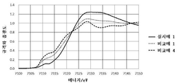
도 1a는, 본 발명의 일 실시형태에 따른 실시예에 있어서, 철의 K 흡수단의 X선 흡수 미세구조 분석을 한 결과의 일례를 나타내는 설명도이다.
도 1b는, 본 발명의 일 실시형태에 따른 실시예에 있어서, 철의 K 흡수단의 X선 흡수 미세구조 분석을 한 결과의 다른 예를 나타내는 설명도이다.
도 2a는, 본 발명의 일 실시형태에 따른 실시예에 있어서, 탄소 촉매를 평가한 결과의 일례를 나타내는 설명도이다.
도 2b는, 본 발명의 일 실시형태에 따른 실시예에 있어서, 탄소 촉매를 평가한 결과의 다른 예를 나타내는 설명도이다.
도 3은 본 발명의 일 실시형태에 따른 실시예에 있어서 공기전지의 최대출력 밀도를 평가한 결과를 나타내는 설명도이다.
도 4는 본 발명의 일 실시형태에 따른 실시예에 있어서 공기전지의 출력 유지율을 평가한 결과를 나타내는 설명도이다.1A is an explanatory diagram showing an example of a result of X-ray absorption microstructure analysis of an iron K absorption end in an embodiment according to an embodiment of the present invention.
1B is an explanatory diagram showing another example of the result of X-ray absorption microstructure analysis of the K absorption end of iron in the embodiment according to the embodiment of the present invention.
2A is an explanatory diagram showing an example of a result of evaluating a carbon catalyst in an example according to an embodiment of the present invention.
2B is an explanatory diagram showing another example of a result of evaluating a carbon catalyst in an example according to an embodiment of the present invention.
3 is an explanatory diagram showing a result of evaluating a maximum output density of an air battery in an embodiment according to an embodiment of the present invention.
4 is an explanatory diagram showing a result of evaluating an output retention rate of an air battery in an embodiment according to an embodiment of the present invention.
이제, 본 발명의 일 실시형태에 따른 탄소 촉매(이하, "본 발명의 촉매"라 칭함), 본 발명의 일 실시형태에 따른 전지 전극(이하, "본 발명의 전극"이라 칭함) 및 본 발명의 일 실시형태에 따른 전지(이하, "본 발명의 전지"라 칭함)에 대해서 설명할 것이다. 또, 본 발명은 본 실시형태에 기재된 예로 한정되지 않는다.Now, a carbon catalyst according to an embodiment of the present invention (hereinafter referred to as "catalyst of the present invention"), a battery electrode according to an embodiment of the present invention (hereinafter referred to as "electrode of the present invention") and the present invention A battery according to an embodiment of the present invention (hereinafter referred to as "battery of the present invention") will be described. Moreover, this invention is not limited to the example described in this embodiment.
본 발명의 발명자들은, 우수한 촉매 활성과 우수한 내구성을 지니는 탄소 촉매를 수득하는 기술적 수단에 대해서 예의 검토를 거듭한 결과, 철을 함유하고, 열중량분석에 의한 중량감소율이 특정한 역치 이하를 나타내는 탄소 촉매이며, 또한 해당 철의 K 흡수단의 X선 흡수 미세구조분석에 있어서, 특정한 상태의 철을 다량 함유하는 탄소구조를 갖는 탄소 촉매가 우수한 촉매 활성과 우수한 내구성을 지니는 것을 독자적으로 발견하여, 본 발명을 완성시키기에 이르렀다.The inventors of the present invention have repeatedly studied the technical means for obtaining a carbon catalyst having excellent catalytic activity and excellent durability, and as a result, a carbon catalyst containing iron and exhibiting a weight reduction rate by thermogravimetric analysis is below a certain threshold. In addition, in the X-ray absorption microstructure analysis of the K absorption end of the corresponding iron, the present invention was independently found that the carbon catalyst having a carbon structure containing a large amount of iron in a specific state has excellent catalytic activity and excellent durability. Came to complete.
본 발명의 촉매는, 철을 함유하고, 질소 분위기하에서의 열중량분석에 의해 측정된 200℃ 내지 1200℃의 온도 범위에서의 중량감소율이 12.0중량% 이하를 나타내고, 해당 철의 K 흡수단의 X선 흡수 미세구조(이하, "XAFS"라 칭함) 분석에 있어서 하기 (a) 및/또는 (b)를 나타내는 탄소구조를 포함한다: (a) 7,110eV에서의 규격화 흡광도에 대한 7,130eV에서의 규격화 흡광도의 비가 7.0 이상임; (b) 7,110eV에서의 규격화 흡광도에 대한 7,135eV에서의 규격화 흡광도의 비가 7.0 이상임. XAFS 분석에 있어서의 규격화 흡광도란, 흡수단의 흡광도가 0에 결속되고, 흡수단 이후의 흡광도가 1에 결속되도록 규격화를 행한 흡광도이다.The catalyst of the present invention contains iron, and the weight loss ratio in the temperature range of 200 ° C to 1200 ° C measured by thermogravimetric analysis in a nitrogen atmosphere is 12.0% by weight or less, and X-rays of the K absorption end of the iron In the absorption microstructure (hereinafter referred to as "XAFS") analysis, the carbon structures represented by (a) and / or (b) are included: (a) Normalized absorbance at 7,130 eV versus normalized absorbance at 7,110 eV Ratio of 7.0 or more; (b) The ratio of the standardized absorbance at 7,135 eV to the standardized absorbance at 7,110 eV is 7.0 or more. The normalized absorbance in XAFS analysis is the absorbance obtained by normalization such that the absorbance at the absorption end is bound to 0, and the absorbance after the absorption end is bound to 1.
본 발명의 촉매는, 후술하는, 그 제조 시에 있어서의 탄소화의 원료에 유래하는 철을 함유한다. 즉, 본 발명의 촉매는, 탄소화의 원료에 철이 포함되어 있었던 것에 기인하여, 그 내부에 해당 철을 함유한다. 이 때문에, 본 발명의 촉매가, 후술의 금속 제거 처리를 거쳐서 제조되었을 경우이더라도, 본 발명의 촉매의 내부에는, 원료 유래의 미량의 철이 잔존한다.The catalyst of the present invention contains iron derived from a raw material for carbonization at the time of its production, which will be described later. That is, the catalyst of the present invention contains iron in its interior due to the fact that iron was included in the raw material for carbonization. For this reason, even when the catalyst of the present invention is produced through the metal removal treatment described later, a trace amount of iron derived from the raw material remains inside the catalyst of the present invention.
구체적으로, 예를 들어, 본 발명의 촉매가 입자 형상일 경우, 본 발명의 촉매를 형성하는 입자를 절단하면, 절단에 의해 노출한 해당 입자의 단면에 철이 검출된다. 이 본 발명의 촉매에 포함되는 철은, 예를 들어, 유도결합 플라즈마(ICP) 발광 분광 광도법에 의해 검출할 수 있다.Specifically, for example, when the catalyst of the present invention is in the form of particles, when the particles forming the catalyst of the present invention are cut, iron is detected on the cross section of the particles exposed by cutting. The iron contained in the catalyst of the present invention can be detected, for example, by inductively coupled plasma (ICP) emission spectrophotometry.
또 본 발명의 촉매는, 질소 분위기하에서의 열중량분석(이하, "TG"라 칭함)에 있어서 측정되는 200℃ 내지 1200℃의 온도 범위에서의 중량감소율이 12.0중량% 이하를 나타낸다. 본 발명의 촉매는, TG에 의한 상기 중량감소율이 바람직하게는 11.0중량% 이하, 더 바람직하게는 10.0중량% 이하, 더욱더 바람직하게는 9.0중량% 이하, 특히 바람직하게는 8.0중량% 이하를 나타낸다.In addition, the catalyst of the present invention exhibits a weight loss ratio of 12.0% by weight or less in a temperature range of 200 ° C to 1200 ° C measured in a thermogravimetric analysis (hereinafter referred to as "TG") under a nitrogen atmosphere. In the catalyst of the present invention, the weight reduction rate by TG is preferably 11.0% by weight or less, more preferably 10.0% by weight or less, even more preferably 9.0% by weight or less, particularly preferably 8.0% by weight or less.
본 발명의 촉매가 상기 특정의 역치 이하의 상기 중량감소율을 나타내는 것은, 본 발명의 촉매가 우수한 내구성에 기여한다. 즉, 질소 분위기하의 TG에 있어서의 탄소 촉매의 중량감소율이 작은 것은, 해당 탄소 촉매가 열적으로 안정적인 것을 나타낸다. 탄소 촉매가 열적으로 안정적인 것은, 예를 들어, 해당 탄소 촉매의 탄소구조를 구성하는 원자간의 결합 에너지가 큰 것에 기인하는 것으로 여겨진다. 이 때문에, 열적으로 안정적인 탄소 촉매는, 전기 화학적으로도 안정하게 된다. 그리고, 전기 화학적으로 안정적인 탄소 촉매는, 연료전지 등의 용도에 있어서, 내구성이 높아진다. 따라서, 질소 분위기하의 TG에 있어서의 중량감소율이 작은 본 발명의 촉매는, 우수한 내구성을 나타낸다. 본 발명의 촉매의 상기 중량감소율의 하한값은 특별히 한정되지 않지만, 해당 중량감소율은 1.0중량% 이상일 수 있다.The fact that the catalyst of the present invention exhibits the weight loss rate below the specified threshold value contributes to the excellent durability of the catalyst of the present invention. That is, a small weight loss rate of the carbon catalyst in TG under a nitrogen atmosphere indicates that the carbon catalyst is thermally stable. It is believed that the carbon catalyst is thermally stable due to, for example, a large binding energy between atoms constituting the carbon structure of the carbon catalyst. For this reason, the thermally stable carbon catalyst is also electrochemically stable. In addition, the electrochemically stable carbon catalyst has high durability in applications such as fuel cells. Therefore, the catalyst of the present invention having a small weight loss rate in TG under a nitrogen atmosphere exhibits excellent durability. The lower limit of the weight loss rate of the catalyst of the present invention is not particularly limited, but the weight loss rate may be 1.0% by weight or more.
또, 본 발명의 촉매의 탄소구조는, 철의 K 흡수단의 XAFS 분석에 있어서, (a) 7,130/7,110비가 7.0 이상을 나타내고, (b) 7,135/7,110비가 7.0 이상을 나타내고, 또는 (a) 7,130/7,110비가 7.0 이상 및 (b) 7,135/7,110비가 7.0 이상을 나타낸다. 본 발명의 촉매의 탄소구조는, 바람직하게는 8.0 이상의 7,130/7,110비 및/또는 7,135/7,110비, 더 바람직하게는, 9.0 이상의 7,130/7,110비 및/또는 7,135/7,110비를 나타낸다.In addition, in the carbon structure of the catalyst of the present invention, in the XAFS analysis of the K absorption end of iron, (a) 7,130 / 7,110 ratio represents 7.0 or more, (b) 7,135 / 7,110 ratio represents 7.0 or more, or (a) The 7,130 / 7,110 ratio represents 7.0 or more and (b) the 7,135 / 7,110 ratio represents 7.0 or more. The carbon structure of the catalyst of the present invention preferably shows a ratio of 7,130 / 7,110 and / or 7,135 / 7,110 of 8.0 or more, more preferably a ratio of 7,130 / 7,110 and / or 7,135 / 7,110 of 9.0 or more.
본 발명의 촉매는, 전술한 중량감소율의 역치의 각각과; 전술한 7,130/7,110비 및/또는 상기 7,135/7,110비의 역치의 각각을 적절하게 조합시킴으로써, 규정될 수 있다.The catalyst of the present invention, each of the threshold of the weight loss rate described above; It can be defined by appropriately combining each of the above-mentioned 7,130 / 7,110 ratios and / or the thresholds of the above 7,135 / 7,110 ratios.
구체적으로, 본 발명의 촉매는, 예를 들어, 바람직하게는 8.0 이상의 7,130/7,110비 및/또는 8.0 이상의 7,135/7,110비를 나타내는 탄소구조를 포함하고, 또한 11.0중량% 이하의 중량감소율을 나타내고, 더 바람직하게는 8.0 이상의 7,130/7,110비 및/또는 8.0 이상의 7,135/7,110비를 나타내는 탄소구조를 포함하고, 또한 10.0중량% 이하의 중량감소율을 나타내며, 더욱더 바람직하게는 9.0 이상의 7,130/7,110비 및/또는 9.0 이상의 7,135/7,110비를 나타내는 탄소구조를 포함하고, 또한 9.0중량% 이하의 중량감소율을 나타내고, 특히 바람직하게는 9.0 이상의 7,130/7,110비 및/또는 9.0 이상의 7,135/7,110비를 나타내는 탄소구조를 포함하고, 또한 8.0중량% 이하의 상기 중량감소율을 나타낸다. 본 발명의 촉매의 7,130/7,110비 및 7,135/7,110비의 상한치는 특별히 한정되지 않지만, 해당 7,130/7,110비 및 7,135/7,110비는 각각 30.0 이하일 수 있다.Specifically, the catalyst of the present invention, for example, preferably includes a carbon structure exhibiting a 7,130 / 7,110 ratio of 8.0 or higher and / or a 7,135 / 7,110 ratio of 8.0 or higher, and also exhibits a weight loss ratio of 11.0% by weight or less, More preferably, it includes a carbon structure showing a 7,130 / 7,110 ratio of 8.0 or more and / or a 7,135 / 7,110 ratio of 8.0 or more, and also shows a weight loss ratio of 10.0% by weight or less, even more preferably a 7,130 / 7,110 ratio of 9.0 or more, and / or Or a carbon structure showing a ratio of 7,135 / 7,110 of 9.0 or more, and also showing a weight loss ratio of 9.0% by weight or less, particularly preferably a carbon structure showing a ratio of 7,130 / 7,110 of 9.0 or more and / or a ratio of 7,135 / 7,110 of 9.0 or more And the weight loss rate of 8.0% by weight or less. The upper limits of the 7,130 / 7,110 ratio and the 7,135 / 7,110 ratio of the catalyst of the present invention are not particularly limited, but the corresponding 7,130 / 7,110 ratio and the 7,135 / 7,110 ratio may be 30.0 or less, respectively.
본 발명의 촉매의 탄소구조가, XAFS 분석에 있어서, 상기 특정의 역치 이상의 7,130/7,110비 및/또는 7,135/7,110비를 나타내는 것은, 본 발명의 촉매의 우수한 촉매 활성에 기여한다. 즉, 철의 K 흡수단의 XAFS 분석에 있어서, 해당 K 흡수단 이후의 피크의 에너지는, 철원자의 1s 궤도의 전자가 σ결합의 반결합성 궤도로 변이되는 에너지를 나타내고 있어, σ 결합의 결합 에너지를 반영하고 있다. 한편, K 흡수단 이전 피크는, 철원자의 1s 궤도의 전자가 d 궤도로 변이되고 있는 것을 나타내고 있으며, 이것은, 철원자가 비대칭한 구조를 갖고 있는 것을 나타내고 있다.The carbon structure of the catalyst of the present invention, in the XAFS analysis, shows a 7,130 / 7,110 ratio and / or a 7,135 / 7,110 ratio above the specified threshold, which contributes to the excellent catalytic activity of the catalyst of the invention. That is, in the XAFS analysis of the K-absorbing end of iron, the energy of the peak after the K-absorbing end represents the energy in which the electrons in the 1s orbit of the iron atom are transformed into the semi-bonding orbit of the σ bond, and the binding energy of the σ bond Is reflected. On the other hand, the peak before the K absorption end indicates that the electron of the 1s orbit of the iron atom is being shifted to the d orbit, which indicates that the iron atom has an asymmetric structure.
따라서, 7,130eV 및 7,135eV에서의 규격화 흡광도가 높다는 것은, 철원자가, 7,130eV 및 7,135eV에 대응하는 에너지를 나타내는 특정한 2종의 결합을 갖는 것을 나타내고, 7,110eV에서의 규격화 흡광도가 높다는 것은, 철원자가 비대칭한 구조를 갖는 것을 나타낸다. 그리고, 본 발명의 촉매에 있어서는, 특정의 2종의 비금속 결합을 갖는 철원자가, 활성점의 하나로서 기능하고 있는 것으로 여겨진다. 따라서, 철의 K 흡수단의 XAFS 분석에 있어서 상기 특정의 역치 이상의 7,130/7,110비 및 7,135/7,110비를 나타내는 탄소구조를 갖는 본 발명의 촉매는, 특정의 2종의 비금속 결합을 갖는 철원자를 비교적 다량 함유함으로써, 우수한 촉매 활성을 지닌다.Therefore, the high standardized absorbance at 7,130 eV and 7,135 eV indicates that the iron atom has a specific two kinds of bonds representing energy corresponding to 7,130 eV and 7,135 eV, and the high standardized absorbance at 7,110 eV is the iron source. It shows that it has an asymmetric structure. In addition, in the catalyst of the present invention, it is considered that an iron atom having two specific nonmetallic bonds functions as one of the active sites. Therefore, in the XAFS analysis of the K absorption end of iron, the catalyst of the present invention having a carbon structure exhibiting 7,130 / 7,110 ratios and 7,135 / 7,110 ratios above the specified thresholds is relatively relatively iron atom having two specific nonmetallic bonds By containing a large amount, it has excellent catalytic activity.
또한, 본 발명의 촉매의 탄소구조가, 철의 XAFS 분석에 있어서, 상기 특정의 역치 이상, 또한 30.0이하의 범위 내의 7,130/7,110비 및 7,135/7,110비를 나타낼 경우, 본 발명의 촉매에 있어서는, 철원자의 특정의 2종의 비금속 결합과, 상기 비대칭 구조가 해당 범위에 대응하는 특정 밸런스로 존재한다. 이 경우, 본 발명의 촉매는, 상기 특정의 2종의 비금속 결합과, 상기 비대칭 구조를 갖는 철원자를 함유함으로써, 우수한 촉매 활성을 지닌다.In addition, when the carbon structure of the catalyst of the present invention exhibits 7,130 / 7,110 ratios and 7,135 / 7,110 ratios within the ranges above the specified threshold and 30.0 or less in XAFS analysis of iron, in the catalyst of the invention, The specific two types of non-metallic bonds of the iron atom and the asymmetric structure exist at a specific balance corresponding to the range. In this case, the catalyst of the present invention has excellent catalytic activity by containing two specific non-metal bonds and an iron atom having the asymmetric structure.
본 발명의 촉매는, 철을 함유하고, 상기 특정의 역치 이하의 중량감소율을 나타내고, 또한 상기 특정의 역치 이상의 7,130/7,110비 및/또는 7,135/7,110비를 나타내는 탄소구조를 갖는 것에 의해, 우수한 촉매 활성과 우수한 내구성을 갖는다.The catalyst of the present invention is an excellent catalyst by containing iron, exhibiting a weight loss ratio below the specified threshold, and having a carbon structure showing 7,130 / 7,110 ratio and / or 7,135 / 7,110 ratio above the specified threshold It has activity and excellent durability.
본 발명의 촉매는, 전체 세공 용적에 대한 메조세공용적의 비율(이하, "메조세공비율"이라 칭함)이 20% 이상일 수도 있다. 이 경우, 본 발명의 촉매의 메조세공비율은 25% 이상인 것이 바람직하다. 본 발명의 촉매의 메조세공비율의 상한치는 특별히 한정되지 않지만, 해당 메조세공비율은, 예를 들어, 70% 이하, 바람직하게는 65% 이하일 수 있다. 본 발명의 촉매의 메조세공비율은, 상기 각 하한값과 각 상한치를 임의로 조합시켜서 규정할 수 있지만, 해당 메조세공비율은, 예를 들어, 바람직하게는 20% 이상 70% 이하, 특히 바람직하게는 25% 이상, 65% 이하이다.In the catalyst of the present invention, the ratio of mesopore volume to total pore volume (hereinafter referred to as "mesopore ratio") may be 20% or more. In this case, the mesopore ratio of the catalyst of the present invention is preferably 25% or more. The upper limit of the mesoporosity ratio of the catalyst of the present invention is not particularly limited, but the mesoporosity ratio may be, for example, 70% or less, preferably 65% or less. The mesoporosity ratio of the catalyst of the present invention can be defined by arbitrarily combining each of the lower limit values and the upper limit values, but the mesoporosity ratio is preferably, for example, 20% or more and 70% or less, particularly preferably 25. % Or more and 65% or less.
본 실시형태에 있어서, 메조세공은, 직경이 2㎚ 이상 50㎚ 이하인 미세 구멍이며, 메조세공용적(㎤/g)은 해당 메조세공의 용적의 총합이다. 또한, 미세세공은, 직경이 2㎚ 미만인 미세 구멍이며, 미세세공용적(㎤/g)은, 해당 미세세공의 용적의 총합이다. 또한, 거대세공은, 직경이 50㎚ 초과의 미세 구멍이며, 거대세공용적(㎤/g)은 해당 거대세공의 용적의 총합이다. 그리고, 전체 세공용적(㎤/g)은, 미세세공용적과 메조세공용적과 거대세공용적의 합계이다.In this embodiment, the mesopores are micropores having a diameter of 2 nm or more and 50 nm or less, and the mesopore volume (cm 3 / g) is the sum of the volumes of the mesopores. The micropores are micropores having a diameter of less than 2 nm, and the micropore volume (cm 3 / g) is the sum of the volumes of the micropores. In addition, the macropores are micropores having a diameter of more than 50 nm, and the macropore volume (cm 3 / g) is the sum of the volumes of the macropores. The total pore volume (cm 3 / g) is the sum of the micropore volume, the mesopore volume, and the macropore volume.
본 발명의 촉매는, 유도결합 플라즈마 질량분석(이하, "ICP-MS"라 칭함)으로부터 측정되는, 철의 함유량이 0.01중량% 이상일 수 있다. 이 경우, 본 발명의 촉매의 상기 철 함유량은, 바람직하게는 0.05중량% 이상, 더 바람직하게는 0.10중량% 이상, 특히 바람직하게는 0.15중량% 이상이다.The catalyst of the present invention may have an iron content of 0.01% by weight or more, as measured by inductively coupled plasma mass spectrometry (hereinafter referred to as "ICP-MS"). In this case, the iron content of the catalyst of the present invention is preferably 0.05% by weight or more, more preferably 0.10% by weight or more, particularly preferably 0.15% by weight or more.
본 발명의 촉매의 ICP-MS에 의해 측정된 철 함유량은, 본 발명의 촉매의 전체 중량에 대한 철원자의 중량의 비율(중량%)로서 산출된다. 본 발명의 촉매의 상기 철 함유량의 상한치는 특별히 한정되지 않지만, 철 함유량은 10.00중량% 이하일 수 있다.The iron content measured by ICP-MS of the catalyst of the present invention is calculated as the ratio (weight%) of the weight of iron atoms to the total weight of the catalyst of the present invention. The upper limit of the iron content of the catalyst of the present invention is not particularly limited, but the iron content may be 10.00% by weight or less.
본 발명의 촉매는 연소법에 기초한 원소분석에 의해 측정된 질소원자 함유량이 1.0중량% 이상을 나타낼 수 있다. 이 경우, 본 발명의 촉매는, 원소분석에 의해 측정된 질소원자 함유량이 바람직하게는 1.1중량% 이상, 특히 바람직하게는 1.2중량% 이상을 나타낸다.The catalyst of the present invention may exhibit a nitrogen atom content of 1.0% by weight or more measured by elemental analysis based on the combustion method. In this case, the catalyst of the present invention preferably has a nitrogen atom content measured by elemental analysis of 1.1% by weight or more, particularly preferably 1.2% by weight or more.
본 발명의 촉매가, 상기 원소분석에 의해 측정된 질소원자 함유량으로서 상기 특정의 역치 이상을 나타내는 것은, 본 발명의 촉매가, 비교적 다량의 질소원자를 함유하는 것을 나타내고 있다. 본 발명의 촉매의 원소분석에 의해 측정된 질소원자 함유량의 상한치는 특별히 한정되지 않지만, 해당 원소분석에 의해 측정된 질소원자 함유량은 10.0중량% 이하일 수 있다.The fact that the catalyst of the present invention exhibits a specific threshold value or more as the nitrogen atom content measured by the elemental analysis indicates that the catalyst of the present invention contains a relatively large amount of nitrogen atoms. The upper limit of the nitrogen atom content measured by elemental analysis of the catalyst of the present invention is not particularly limited, but the nitrogen atom content measured by the elemental analysis may be 10.0% by weight or less.
또한, 본 발명의 촉매는, X선광전자분광법(이하, "XPS"라 칭함)에 의해 측정된 질소원자 농도가 1.0 atm% 이상을 나타내고, 또한 연소법에 기초한 원소분석에 의해 측정된 질소원자 함유량이 1.0중량% 이상을 나타낼 수 있다.In addition, the catalyst of the present invention has a nitrogen atom concentration of 1.0 atm% or more measured by X-ray photoelectron spectroscopy (hereinafter referred to as "XPS"), and a nitrogen atom content measured by elemental analysis based on the combustion method. 1.0% by weight or more.
이 경우, 본 발명의 촉매는, 바람직하게는 XPS에 의해 측정된 질소원자 농도가 1.1 atm% 이상 그리고 원소분석에 의해 측정된 질소원자 함유량이 1.1중량% 이상을 나타내고, 특히 바람직하게는 XPS에 의해 측정된 질소원자 농도가 1.2 atm% 이상 그리고 원소분석에 의해 측정된 질소원자 함유량이 1.2중량% 이상을 나타낸다.In this case, the catalyst of the present invention preferably has a nitrogen atom concentration of 1.1 atm% or more measured by XPS and a nitrogen atom content of 1.1% by weight or more measured by elemental analysis, particularly preferably by XPS. The measured nitrogen atom concentration is 1.2 atm% or more and the nitrogen atom content measured by elemental analysis is 1.2 wt% or more.
본 발명의 촉매가, XPS에 의해 측정된 질소원자 농도로서 상기 특정의 역치 이상, 그리고 상기 원소분석에 의해 측정된 질소원자 함유량으로서 상기 특정의 역치 이상을 나타내는 것은, 본 발명의 촉매가, 그 표층부분(표면에서부터 수 ㎚의 깊이까지의 부분)뿐만 아니라, 그 내부(해당 표층부분보다 깊은 내부)에도 해당 표층부분과 동등한 양의 질소원자를 함유하는 것, 즉, 그 표층부분으로부터 내부까지 비교적 균질한 탄소 구조를 갖고 있는 것을 반영하고 있다.It is noted that the catalyst of the present invention exhibits the above specified threshold as the nitrogen atom concentration measured by XPS, and the above specified threshold as the nitrogen atom content measured by the elemental analysis. Not only the part (the part from the surface to a depth of several nm), but also the inside (the inside deeper than the corresponding surface part) contains the same amount of nitrogen atom as the surface part, that is, relatively homogeneous from the surface part to the inside It reflects a carbon structure.
그리고, 본 발명의 촉매가, 위에서 기재된 바와 같은 표층부분으로부터 내부까지 비교적 균질한 탄소구조를 갖는 것에 의해, 예를 들어, 해당 표층부분의 활성점이 상실되었을 경우이더라도, 해당 표층부분보다 깊은 내부의 활성점이 기능함으로써, 본 발명의 촉매의 촉매 활성의 저하가 효과적으로 억제된다.And, the catalyst of the present invention has a relatively homogeneous carbon structure from the surface layer portion to the interior as described above, for example, even when the active point of the surface layer portion is lost, the internal activity deeper than the surface layer portion When the point functions, a decrease in catalytic activity of the catalyst of the present invention is effectively suppressed.
본 발명의 촉매의 XPS에 의해 측정된 질소원자 농도, 및 원소분석에 의해 측정된 질소원자 함유량의 상한치는 특별히 한정되지 않지만, 해당 XPS에 의해 측정된 질소원자 농도는 10.0 atm% 이하일 수 있고, 해당 원소분석에 의해 측정된 질소원자 함유량은 10.0중량% 이하일 수 있다.The upper limit of the nitrogen atom concentration measured by XPS of the catalyst of the present invention and the nitrogen atom content measured by elemental analysis is not particularly limited, but the nitrogen atom concentration measured by the XPS may be 10.0 atm% or less, The nitrogen atom content measured by elemental analysis may be 10.0% by weight or less.
본 발명의 촉매는, 연소법에 기초한 원소분석에 의해 측정된, 1.1% 이상의 탄소원자 함유량에 대한 질소원자 함유량의 비율(이하, "원소분석에 의해 측정된 N/C 비율"이라 칭함)을 나타낼 수 있다. 이 경우, 본 발명의 촉매는, 바람직하게는 1.2% 이상, 특히 바람직하게는 1.3% 이상의 원소분석에 의해 측정된 N/C 비율을 나타낸다.The catalyst of the present invention can exhibit a ratio of nitrogen atom content to carbon atom content of 1.1% or more as measured by elemental analysis based on the combustion method (hereinafter referred to as "N / C ratio measured by element analysis"). have. In this case, the catalyst of the present invention preferably exhibits an N / C ratio measured by elemental analysis of at least 1.2%, particularly preferably at least 1.3%.
본 발명의 촉매가, 상기 원소분석에 의해 측정된 N/C 비율로서 상기 특정의 역치 이상을 나타내는 것은, 본 발명의 촉매가 비교적 다량의 질소원자를 함유하는 것을 나타낸다. 본 발명의 촉매의 원소분석에 의해 측정된 N/C 비율의 상한치는 특별히 한정되지 않지만, 15.0% 이하일 수 있다.The catalyst of the present invention exhibiting a specific threshold value or more as the N / C ratio measured by the elemental analysis indicates that the catalyst of the present invention contains a relatively large amount of nitrogen atoms. The upper limit of the N / C ratio measured by elemental analysis of the catalyst of the present invention is not particularly limited, but may be 15.0% or less.
또한, 본 발명의 촉매는, XPS에 의해 측정된, 탄소원자 농도에 대한 질소원자 농도의 비율(이하, "XPS에 의한 N/C 비율"이라 칭함)이 1.1% 이상을 나타낼 수 있고, 연소법에 의한 원소분석에 의해 측정된 N/C 비율이 1.1% 이상 나타낼 수 있다.In addition, the catalyst of the present invention, the ratio of the nitrogen atom concentration to the carbon atom concentration (hereinafter referred to as "N / C ratio by XPS") measured by XPS may exhibit 1.1% or more, and the combustion method The N / C ratio measured by elemental analysis may be more than 1.1%.
이 경우, 본 발명의 촉매는, 바람직하게는 XPS에 의한 N/C 비율이 1.2% 이상 그리고 원소분석에 의해 측정된 N/C 비율이 1.2% 이상을 나타내고, 특히 바람직하게는 XPS에 의한 N/C 비율이 1.3% 이상 그리고 원소분석에 의해 측정된 N/C 비율이 1.3% 이상을 나타낸다.In this case, the catalyst of the present invention preferably has an N / C ratio of 1.2% or more by XPS and an N / C ratio measured by elemental analysis of 1.2% or more, particularly preferably N / C by XPS. The C ratio is 1.3% or more, and the N / C ratio measured by elemental analysis is 1.3% or more.
본 발명의 촉매가, XPS에 의한 N/C 비율로서 상기 특정의 역치 이상을 나타내고, 또한 원소분석에 의해 측정된 N/C 비율로서 상기 특정의 역치 이상을 나타내는 것은, 본 발명의 촉매가, 그 표층부분(표면에서 수 ㎚의 깊이까지의 부분)뿐만 아니라, 그 내부(해당 표층부분보다 깊은 내부)에도 해당 표층부분과 동등한 양의 질소원자를 함유하는 것을 반영하고 있다.The catalyst of the present invention exhibits the above-mentioned specific threshold or more as an N / C ratio by XPS, and the catalyst of the present invention exhibits the above-mentioned specific threshold or more as an N / C ratio measured by elemental analysis. In addition to the surface layer portion (the portion from the surface to a depth of several nm), the inside (inside deeper than the surface layer portion) reflects the same amount of nitrogen atoms as the surface layer portion.
본 발명의 촉매가, 위에서 기재된 바와 같이 표층부분으로부터 내부까지 비교적 균질한 탄소구조를 갖는 것에 의해, 예를 들어, 해당 표층부분의 활성점이 손실되어버렸을 경우이더라도, 해당 표층부분보다 깊은 내부의 활성점이 기능함으로써, 본 발명의 촉매의 촉매 활성의 저하가 효과적으로 억제된다.Since the catalyst of the present invention has a relatively homogeneous carbon structure from the surface layer portion to the interior as described above, for example, even when the active point of the surface layer portion is lost, the internal activity point deeper than the surface layer portion By functioning, reduction of the catalytic activity of the catalyst of the present invention is effectively suppressed.
본 발명의 촉매의 XPS에 의한 N/C 비율, 및 원소분석에 의해 측정된 N/C 비율의 상한치는 특별히 한정되지 않지만, 해당 XPS에 의한 N/C 비율은 15.0% 이하일 수 있고, 또한 해당 원소분석에 의해 측정된 N/C 비율은 15.0% 이하일 수 있다.The upper limit of the N / C ratio by the XPS of the catalyst of the present invention and the N / C ratio measured by elemental analysis is not particularly limited, but the N / C ratio by the XPS may be 15.0% or less, and the corresponding element The N / C ratio determined by analysis may be 15.0% or less.
본 발명의 촉매는, 철 이외의 금속(이하, "비철금속"이라 칭함)을 더 함유할 수 있다. 이 경우, 본 발명의 촉매에 함유되는 비철금속은, 전술한 본 발명의 촉매의 특성이 얻어지는 것이면 특별히 한정되지 않지만, 전이금속인 것이 바람직하다.The catalyst of the present invention may further contain a metal other than iron (hereinafter referred to as "non-ferrous metal"). In this case, the non-ferrous metal contained in the catalyst of the present invention is not particularly limited as long as the properties of the catalyst of the present invention described above are obtained, but is preferably a transition metal.
본 실시형태에 있어서, 비철금속은, 주기율표의 III족 내지 XII족에 속하는 금속이며, 주기율표의 III족 내지 XII족의 제4주기에 속하는 전이금속인 것이 바람직하다. 구체적으로, 본 발명의 촉매에 함유되는 비철금속은, 예를 들어, 스칸듐(Sc), 티타늄(Ti), 바나듐(V), 크롬(Cr), 망간(Mn), 코발트(Co), 니켈(Ni), 구리(Cu), 아연(Zn), 이트륨(Y), 지르코늄(Zr), 니오브(Nb), 몰리브덴(Mo), 루테늄(Ru), 로듐(Rh), 팔라듐(Pd), 은(Ag), 란타노이드(예를 들어, 네오디뮴(Nd), 사마륨(Sm) 및 가돌리늄(Gd)으로 이루어진 군으로부터 선택되는 1종 이상) 및 악티노이드로 이루어진 군, 또는 Sc, Ti, V, Cr, Mn, Co, Ni, Cu, Zn, Y, Zr, Nb, Mo, Ag, 란타노이드(예를 들어, Nd, Sm 및 Gd로 이루어진 군으로부터 선택되는 1종 이상) 및 악티노이드로 이루어진 군으로부터 선택되는 1종 이상일 수 있다.In the present embodiment, the non-ferrous metal is preferably a metal belonging to group III to XII of the periodic table, and a transition metal belonging to the fourth period of group III to XII of the periodic table. Specifically, the non-ferrous metal contained in the catalyst of the present invention, for example, scandium (Sc), titanium (Ti), vanadium (V), chromium (Cr), manganese (Mn), cobalt (Co), nickel (Ni ), Copper (Cu), zinc (Zn), yttrium (Y), zirconium (Zr), niobium (Nb), molybdenum (Mo), ruthenium (Ru), rhodium (Rh), palladium (Pd), silver (Ag) ), Lanthanoids (e.g., one or more selected from the group consisting of neodymium (Nd), samarium (Sm) and gadolinium (Gd)) and actinoids, or Sc, Ti, V, Cr, Mn , Co, Ni, Cu, Zn, Y, Zr, Nb, Mo, Ag, lanthanoids (e.g., one or more selected from the group consisting of Nd, Sm and Gd) and actinoids It may be one or more.
또한, 본 발명의 촉매는, 바람직하게는 Fe와, Ti, Cr, Zn, Nd, Sm 및 Gd로 이루어진 군으로부터 선택되는 1종 이상의 비철금속을 함유한다. 이 경우, 본 발명의 촉매는, 예를 들어, Fe 및 Zn을 함유할 수 있다.Further, the catalyst of the present invention preferably contains Fe and at least one non-ferrous metal selected from the group consisting of Ti, Cr, Zn, Nd, Sm and Gd. In this case, the catalyst of the present invention may contain Fe and Zn, for example.
본 발명의 촉매가 비철금속으로서 상기 특정의 전이금속을 함유할 경우, 본 발명의 촉매는 또 다른 전이금속을 더 함유할 수 있다. 즉, 예를 들어, 본 발명의 촉매가 Fe와, Ti, Cr, Zn, Nd, Sm 및 Gd로 이루어진 군으로부터 선택되는 1종 이상의 제1 비철전이금속을 함유할 경우, Sc, Ti, V, Cr, Mn, Co, Ni, Cu, Y, Zr, Nb, Mo, Ru, Rh, Pd, Ag, 란타노이드(예를 들어, Nd, Sm 및 Gd로 이루어진 군으로부터 선택되는 1종 이상) 및 악티노이드로 이루어진 군, 또는 Sc, Ti, V, Cr, Mn, Co, Ni, Cu, Zn, Y, Zr, Nb, Mo, Ag, 란타노이드(예를 들어, Nd, Sm 및 Gd로 이루어진 군으로부터 선택되는 1종 이상) 및 악티노이드로 이루어진 군으로부터 선택되는 1종 이상이며 해당 제1 비철전이금속과는 다른 제2 비철전이금속을 더 함유할 수 있다.When the catalyst of the present invention contains the above specific transition metal as a non-ferrous metal, the catalyst of the present invention may further contain another transition metal. That is, for example, when the catalyst of the present invention contains at least one first non-ferrous transition metal selected from the group consisting of Fe, Ti, Cr, Zn, Nd, Sm and Gd, Sc, Ti, V, Cr, Mn, Co, Ni, Cu, Y, Zr, Nb, Mo, Ru, Rh, Pd, Ag, Lanthanoids (e.g., one or more selected from the group consisting of Nd, Sm and Gd) and Acti From the group consisting of noids, or Sc, Ti, V, Cr, Mn, Co, Ni, Cu, Zn, Y, Zr, Nb, Mo, Ag, lanthanoids (e.g., from the group consisting of Nd, Sm and Gd) And one or more selected from the group consisting of actinoids, and may further contain a second non-ferrous transition metal different from the first non-ferrous transition metal.
또 본 발명의 촉매는 백금(Pt)을 함유하지 않을 수 있다. 본 발명의 촉매는, 백금(Pt), 루테늄(Ru), 로듐(Rh), 팔라듐(Pd), 이리듐(Ir), 금(Au) 및 오스뮴(Os)으로 이루어진 군으로부터 선택되는 1종 이상을 함유하지 않을 수 있다.In addition, the catalyst of the present invention may not contain platinum (Pt). The catalyst of the present invention, at least one selected from the group consisting of platinum (Pt), ruthenium (Ru), rhodium (Rh), palladium (Pd), iridium (Ir), gold (Au) and osmium (Os) It may not contain.
본 발명의 촉매가, 철에 부가해서, 후술하는 탄소화의 원료에 유래하는 비철금속을 포함할 경우, 본 발명의 촉매는, 탄소화의 원료에 해당 철 및 비철금속이 포함되어 있었던 것에 기인하고, 그 내부에 해당 철과 해당 비철금속을 포함한다. 즉, 본 발명의 촉매가, 후술의 금속 제거 처리를 거쳐서 제조되었을 경우에 있어서도, 본 발명의 촉매의 내부에는, 미량의 해당 철 및 비철금속이 잔존한다.When the catalyst of the present invention contains, in addition to iron, a non-ferrous metal derived from a carbonized raw material, which will be described later, the catalyst of the present invention is due to the fact that the iron and non-ferrous metal were contained in the carbonized raw material. The iron and the corresponding non-ferrous metal are included inside. That is, even when the catalyst of the present invention is produced through a metal removal treatment described later, a small amount of the corresponding iron and non-ferrous metal remains inside the catalyst of the present invention.
구체적으로, 예를 들어, 철 및 비철금속을 함유하는 본 발명의 촉매가 입자형상일 경우, 본 발명의 촉매를 형성하는 입자를 절단하면, 절단에 의해 노출된 해당 입자의 단면에 해당 철 및 비철금속이 검출된다. 본 발명의 촉매에 함유되는 철 및 비철금속은, 예를 들어, 유도결합 플라즈마(ICP) 발광 분광 광도법에 의해 검출할 수 있다.Specifically, for example, when the catalyst of the present invention containing iron and a non-ferrous metal is in the form of particles, when cutting the particles forming the catalyst of the present invention, the corresponding iron and non-ferrous metals are formed on the cross-section of the particles exposed by cutting. Is detected. The ferrous and non-ferrous metals contained in the catalyst of the present invention can be detected by, for example, inductively coupled plasma (ICP) emission spectrophotometry.
본 발명의 촉매는, BET법에 의해 측정된 비표면적이 800 ㎡/g 이상일 수 있다. 이 경우, 질소 가스를 이용한 BET법에 의한 본 발명의 촉매의 비표면적은, 바람직하게는 1,000 ㎡/g 이상, 특히 바람직하게는 1,200 ㎡/g 이상이다.The catalyst of the present invention may have a specific surface area of 800 m 2 / g or more measured by the BET method. In this case, the specific surface area of the catalyst of the present invention by the BET method using nitrogen gas is preferably 1,000 m 2 / g or more, particularly preferably 1,200 m 2 / g or more.
본 발명의 촉매의 비표면적이 상기 특정 역치 이상인 것은, 본 발명의 촉매에 의한 화학반응의 효율화에 기여하고, 우수한 촉매 활성에 기여한다. 본 발명의 촉매의 상기 비표면적의 상한치는 특별히 한정되지 않지만, 해당 비표면적은, 3,000㎡/g 이하일 수 있다.When the specific surface area of the catalyst of the present invention is greater than or equal to the above specified threshold, it contributes to the efficiency of the chemical reaction by the catalyst of the present invention and contributes to excellent catalytic activity. Although the upper limit of the specific surface area of the catalyst of the present invention is not particularly limited, the specific surface area may be 3,000 m 2 / g or less.
본 발명의 촉매는, 그 자체로 촉매 활성을 지니는 탄소재료이다. 본 발명의 촉매를 형성하는 탄소재료는, 예를 들어, 후술하는 바와 같이 유기물을 함유하는 원료의 탄소화에 의해 얻어진 탄소화 재료 및 철이다. 또한, 본 발명의 촉매가, 유기물과 금속을 함유하는 원료의 탄소화에 의해 얻어진 탄소화 재료, 철 및 비철금속일 경우, 본 발명의 촉매의 탄소구조에는 해당 비철금속이 포함된다. 이 경우에, 본 발명의 촉매의 촉매 활성은, 해당 비철금속보다도, 주로 철과 해당 탄소구조 자체에 함유되는 활성점에 의한 것으로 여겨진다. 본 발명의 촉매가 지니는 촉매 활성은, 예를 들어, 산화 활성, 및/또는 환원 활성이며, 보다 구체적으로는, 예를 들어, 산소 환원 활성 및/또는 수소 산화 활성이다.The catalyst of the present invention is itself a carbon material having catalytic activity. The carbon material forming the catalyst of the present invention is, for example, a carbonized material and iron obtained by carbonization of a raw material containing an organic material, as described later. Further, when the catalyst of the present invention is a carbonized material obtained by carbonization of a raw material containing an organic substance and a metal, iron and a non-ferrous metal, the carbon structure of the catalyst of the present invention includes the non-ferrous metal. In this case, it is considered that the catalytic activity of the catalyst of the present invention is mainly due to the active point contained in iron and the carbon structure itself, rather than the non-ferrous metal. The catalytic activity possessed by the catalyst of the present invention is, for example, oxidizing activity and / or reducing activity, and more specifically, for example, oxygen reducing activity and / or hydrogen oxidation activity.
본 발명의 촉매는, 그 자체가 단독으로 촉매 활성을 지니므로, 본 발명의 촉매는 Pt를 함유하지 않을 수 있거나, 또는 본 발명의 촉매는 Pt와 같은 희소 금속을 함유하지 않을 수도 있다. 그러나, 본 발명의 촉매는, 이것으로 한정되지 않고, 예를 들어, 해당 희소금속을 담지하는 담체로서 이용될 수 있어도 된다. 이 경우, 본 발명의 촉매에 담지되는 희소금속은, 예를 들어, Pt, Ru, Rh, Pd, Ir, Au 및 Os로 이루어진 군으로부터 선택되는 1종 이상이다.Since the catalyst of the present invention itself has catalytic activity alone, the catalyst of the present invention may not contain Pt, or the catalyst of the present invention may not contain rare metals such as Pt. However, the catalyst of the present invention is not limited to this, and may be used, for example, as a carrier supporting the rare metal. In this case, the rare metal supported on the catalyst of the present invention is, for example, one or more selected from the group consisting of Pt, Ru, Rh, Pd, Ir, Au and Os.
본 발명의 촉매가, 희소금속의 담체로서 이용되는 경우이더라도, 아직 해당 희소금속을 담지하고 있지 않은 담체로서의 본 발명의 촉매(해당 희소금속을 담지하기 전의 본 발명의 촉매)는, 그 자체가 촉매 활성을 지니는 탄소재료, 즉, 탄소 촉매이다.Even if the catalyst of the present invention is used as a carrier for a rare metal, the catalyst of the present invention (the catalyst of the present invention before carrying the rare metal) as a carrier that does not yet support the rare metal is itself a catalyst It is an active carbon material, that is, a carbon catalyst.
본 발명의 촉매의 제조 방법은, 전술한 특성을 지니는 탄소 촉매가 얻어지는 방법이면 특별히 한정되지 않지만, 본 실시형태에 있어서는, 유기물 및 철을 함유하는 원료를 가압 하에 탄소화시키는 것을 포함하는 방법에 대해서 설명한다.The method for producing the catalyst of the present invention is not particularly limited as long as it is a method in which a carbon catalyst having the above-described properties is obtained, but in the present embodiment, a method including carbonizing a raw material containing an organic substance and iron under pressure is described. do.
원료에 함유되는 유기물은, 탄소화될 수 있는 것이면 특별히 한정되지 않는다. 구체적으로, 유기물로서는, 예를 들어, 고분자량의 유기 화합물(예를 들어, 열경화성 수지 및/또는 열가소성 수지 등의 수지) 및/또는 저분자량의 유기 화합물이 사용된다. 또한, 유기물로서 바이오매스가 사용될 수도 있다.The organic substance contained in the raw material is not particularly limited as long as it can be carbonized. Specifically, as the organic material, for example, a high molecular weight organic compound (for example, a resin such as a thermosetting resin and / or a thermoplastic resin) and / or a low molecular weight organic compound are used. In addition, biomass may be used as an organic material.
유기물로서는, 질소-함유 유기물이 바람직하게 사용된다. 질소-함유 유기물은, 그 분자 내에 질소원자를 함유하는 유기 화합물을 함유하는 유기물이면 특별히 한정되지 않는다. 본 발명의 촉매가, 질소-함유 유기물을 함유하는 원료의 탄소화물일 경우, 본 발명의 촉매의 탄소구조는 질소원자를 함유한다.As the organic material, a nitrogen-containing organic material is preferably used. The nitrogen-containing organic substance is not particularly limited as long as it is an organic substance containing an organic compound containing a nitrogen atom in the molecule. When the catalyst of the present invention is a carbohydrate of a raw material containing a nitrogen-containing organic substance, the carbon structure of the catalyst of the present invention contains a nitrogen atom.
구체적으로, 유기물은, 예를 들어, 폴리아크릴로나이트릴, 폴리아크릴로나이트릴-폴리아크릴산 공중합체, 폴리아크릴로나이트릴-폴리아크릴산 메틸 공중합체, 폴리아크릴로나이트릴-폴리메타크릴산 공중합체, 폴리아크릴로나이트릴-폴리메타크릴산-폴리메탈릴설폰산 공중합체, 폴리아크릴로나이트릴-폴리메타크릴산 메틸 공중합체, 페놀 수지, 폴리푸르푸릴 알코올, 퓨란, 퓨란 수지, 페놀 폼알데하이드 수지, 멜라민, 멜라민 수지, 에폭시 수지, 질소-함유 킬레이트 수지(예를 들어, 폴리아민형, 이미노다이아세트산형, 아미노인산형 및 아미노메틸포스폰산형으로 이루어진 군으로부터 선택되는 1종 이상), 폴리아마이드-이미드 수지, 피롤, 폴리피롤, 폴리비닐피롤, 3-메틸폴리피롤, 아크릴로나이트릴, 폴리염화비닐리덴, 티오펜, 옥사졸, 티아졸, 피라졸, 비닐피리딘, 폴리비닐피리딘, 피리다진, 피리미딘, 피페라진, 피란, 몰폴린, 이미다졸, 1-메틸이미다졸, 2-메틸이미다졸, 퀴녹살린, 아닐린, 폴리아닐린, 숙신산 다이하이드라자이드, 아디프산 다이하이드라자이드, 폴리설폰, 폴리아미노비스말레이미드, 폴리이미드, 폴리비닐알코올, 폴리비닐부티랄, 벤조이미다졸, 폴리벤조이미다졸, 폴리아마이드, 폴리에스터, 폴리락트산, 폴리에터, 폴리에터에터케톤, 셀룰로스, 카복시메틸셀룰로스, 리그닌, 키틴, 키토산, 피치, 갈탄, 비단, 털, 폴리아미노산, 핵산, DNA, RNA, 하이드라진, 하이드라자이드, 요소, 살렌(salen), 폴리카바졸, 폴리비스말레이미드, 트라이아진, 폴리아크릴산, 폴리아크릴산 에스터, 폴리메타크릴산 에스터, 폴리메타크릴산, 폴리우레탄, 폴리아미도아민 및 폴리카보다이이미드로 이루어진 군으로부터 선택되는 1종 이상일 수 있다.Specifically, the organic material is, for example, polyacrylonitrile, polyacrylonitrile-polyacrylic acid copolymer, polyacrylonitrile-polyacrylic acid methyl copolymer, polyacrylonitrile-polymethacrylic acid copolymer Copolymer, polyacrylonitrile-polymethacrylic acid-polymetalylsulfonic acid copolymer, polyacrylonitrile-polymethacrylic acid methyl copolymer, phenol resin, polyfurfuryl alcohol, furan, furan resin, phenol formaldehyde resin , Melamine, melamine resin, epoxy resin, nitrogen-containing chelating resin (for example, at least one selected from the group consisting of polyamine type, iminodiacetic acid type, aminophosphoric acid type and aminomethylphosphonic acid type), polyamide- Imide resin, pyrrole, polypyrrole, polyvinylpyrrole, 3-methylpolypyrrole, acrylonitrile, polyvinylidene chloride, thiophene, oxazole, thiazole, pi Sol, vinylpyridine, polyvinylpyridine, pyridazine, pyrimidine, piperazine, pyran, morpholine, imidazole, 1-methylimidazole, 2-methylimidazole, quinoxaline, aniline, polyaniline, succinic acid dihai Drazide, adipic acid dihydrazide, polysulfone, polyaminobismaleimide, polyimide, polyvinyl alcohol, polyvinyl butyral, benzoimidazole, polybenzoimidazole, polyamide, polyester, polylactic acid, Polyether, polyetheretherketone, cellulose, carboxymethylcellulose, lignin, chitin, chitosan, peach, lignite, silk, hair, polyamino acid, nucleic acid, DNA, RNA, hydrazine, hydrazide, urea, salen ( salen), consisting of polycarbazole, polybismaleimide, triazine, polyacrylic acid, polyacrylic acid ester, polymethacrylic acid ester, polymethacrylic acid, polyurethane, polyamidoamine and polycarbodiimide It may be at least one member selected from the group.
원료에 있어서의 유기물의 함유량은, 본 발명의 촉매가 얻어지는 범위이면 특별히 한정되지 않지만, 예를 들어, 5질량% 이상 90질량% 이하, 바람직하게는 10질량% 이상 80질량% 이하일 수 있다.The content of the organic substance in the raw material is not particularly limited as long as the catalyst of the present invention is obtained, but may be, for example, 5% by mass to 90% by mass, preferably 10% by mass to 80% by mass.
탄소화의 원료에 함유되는 철로서는, 해당 철의 단체 및/또는 해당 철의 화합물이 사용된다. 철 화합물로서는, 예를 들어, 철의 염, 철의 산화물, 철의 수산화물, 철의 질화물, 철의 황화물, 철의 탄화물 및 철의 착체로 이루어진 군으로부터 선택되는 1종 이상을 사용할 수 있다.As the iron contained in the carbonized raw material, a simple substance of the iron and / or a compound of the iron is used. As the iron compound, for example, one or more selected from the group consisting of iron salt, iron oxide, iron hydroxide, iron nitride, iron sulfide, iron carbide and iron complex can be used.
원료에 있어서의 철의 함유량은, 본 발명의 촉매가 얻어지는 범위이면 특별히 한정되지 않지만, 예를 들어, 0.001질량% 이상 90질량% 이하, 바람직하게는 0.002질량% 이상 80질량% 이하인 것이 바람직하다.The content of iron in the raw material is not particularly limited as long as the catalyst of the present invention is obtained, but it is preferably, for example, 0.001 mass% or more and 90 mass% or less, preferably 0.002 mass% or more and 80 mass% or less.
탄소화의 원료는 비철금속을 더 함유할 수 있다. 이 경우, 유기물과 철과 비철금속을 함유하는 원료가 가압 하에서 탄소화된다. 본 발명의 촉매가, 유기물과 철과 비철금속을 함유하는 원료의 탄소화에 의해 얻어지는 탄소화 재료일 경우, 본 발명의 촉매는, 해당 철 및 비철금속을 포함한다. 원료에 함유되는 비철금속은, 전술한 본 발명의 촉매의 특성이 얻어지는 것이면 특별히 한정되지 않는다. 비철금속은 전이금속인 것이 바람직하다.The carbonization raw material may further contain a non-ferrous metal. In this case, organic materials and raw materials containing iron and non-ferrous metals are carbonized under pressure. When the catalyst of the present invention is a carbonized material obtained by carbonization of an organic material and a raw material containing iron and a non-ferrous metal, the catalyst of the present invention includes the iron and non-ferrous metal. The non-ferrous metal contained in the raw material is not particularly limited as long as the characteristics of the catalyst of the present invention described above are obtained. It is preferable that the non-ferrous metal is a transition metal.
본 실시형태에 있어서, 비철금속은, 주기율표의 III족 내지 XII족의 제4 주기에 속하는 전이금속이고, 바람직하게는 주기율표의 III족 내지 XII족에 속하는 금속이고, 바람직하게는 주기율표의 III족 내지 XII족 중 제4주기에 속하는 전이금속이다. 구체적으로, 원료에 함유되는 비철금속은, 예를 들어, Sc, Ti, V, Cr, Mn, Co, Ni, Cu, Zn, Y, Zr, Nb, Mo, Ru, Rh, Pd, Ag, 란타노이도(예를 들어, Nd, Sm 및 Gd로 이루어진 군으로부터 선택된 1종 이상) 및 악티노이드로 이루어진 군, 또는 Sc, Ti, V, Cr, Mn, Co, Ni, Cu, Zn, Y, Zr, Nb, Mo, Ag, 란타노이도(예를 들어, Nd, Sm 및 Gd로 이루어진 군으로부터 선택된 1종 이상) 및 악티노이드로 이루어진 군으로부터 선택되는 1종 이상일 수 있다.In the present embodiment, the non-ferrous metal is a transition metal belonging to the fourth period of Group III to XII of the periodic table, preferably a metal belonging to Group III to XII of the periodic table, preferably Group III to XII of the periodic table It is a transition metal belonging to the fourth cycle of the family. Specifically, the non-ferrous metal contained in the raw material, for example, Sc, Ti, V, Cr, Mn, Co, Ni, Cu, Zn, Y, Zr, Nb, Mo, Ru, Rh, Pd, Ag, lanthanoid Figure (e.g., one or more selected from the group consisting of Nd, Sm and Gd) and the group consisting of actinoids, or Sc, Ti, V, Cr, Mn, Co, Ni, Cu, Zn, Y, Zr, Nb, Mo, Ag, lanthanoid (eg, one or more selected from the group consisting of Nd, Sm and Gd) and one or more selected from the group consisting of actinoids.
또한, 원료는, Fe와, Ti, Cr, Zn, Nd, Sm 및 Gd로 이루어진 군으로부터 선택되는 1종 이상의 비철금속을 포함하는 것이 바람직하다. 이 경우, 원료는 Fe 및 Zn을 함유할 수 있다.In addition, it is preferable that the raw material contains Fe and at least one non-ferrous metal selected from the group consisting of Ti, Cr, Zn, Nd, Sm and Gd. In this case, the raw materials may contain Fe and Zn.
원료가 철에 부가해서 비철금속으로서 상기 특정의 전이금속을 함유할 경우, 해당 원료는 또 다른 전이금속을 더 포함할 수 있다. 즉, 예를 들어, 원료가 Fe와, Ti, Cr, Fe, Zn, Nd, Sm 및 Gd로 이루어진 군으로부터 선택되는 1종 이상의 제1 비철전이금속을 포함할 경우, Sc, Ti, V, Cr, Mn, Co, Ni, Cu, Zn, Y, Zr, Nb, Mo, Ru, Rh, Pd, Ag, 란타노이드(예를 들어, Nd, Sm 및 Gd로 이루어진 군으로부터 선택되는 1종 이상) 및 악티노이드로 이루어진 군, 또는 Sc, Ti, V, Cr, Mn, Co, Ni, Cu, Zn, Y, Zr, Nb, Mo, Ag, 란타노이드(예를 들어, Nd, Sm 및 Gd로 이루어진 군으로부터 선택되는 1종 이상) 및 악티노이드로 이루어진 군으로부터 선택되는 1종 이상이며 해당 제1 비철전이금속과는 다른 제2 비철전이금속을 더 포함할 수도 있다.When the raw material contains the specific transition metal as a non-ferrous metal in addition to iron, the raw material may further include another transition metal. That is, for example, when the raw material includes Fe, Ti, Cr, Fe, Zn, Nd, Sm and one or more first non-ferrous transition metals selected from the group consisting of Gd, Sc, Ti, V, Cr , Mn, Co, Ni, Cu, Zn, Y, Zr, Nb, Mo, Ru, Rh, Pd, Ag, lanthanoid (for example, one or more selected from the group consisting of Nd, Sm and Gd) and The group consisting of actinoids, or the group consisting of Sc, Ti, V, Cr, Mn, Co, Ni, Cu, Zn, Y, Zr, Nb, Mo, Ag, lanthanoids (eg, Nd, Sm and Gd And at least one selected from the group consisting of actinoids, and may further include a second non-ferrous transition metal different from the first non-ferrous transition metal.
또 원료는 백금(Pt)을 함유하지 않을 수 있다. 이 경우, 원료는, 백금(Pt), 루테늄(Ru), 로듐(Rh), 팔라듐(Pd), 이리듐(Ir), 금(Au) 및 오스뮴(Os)으로 이루어진 군으로부터 선택되는 1종 이상을 함유하지 않을 수 있다.In addition, the raw material may not contain platinum (Pt). In this case, the raw material is one or more selected from the group consisting of platinum (Pt), ruthenium (Ru), rhodium (Rh), palladium (Pd), iridium (Ir), gold (Au) and osmium (Os). It may not contain.
원료에 함유된 비철금속으로서는, 해당 비철금속의 단체 및/또는 해당 비철금속의 화합물이 사용된다. 비철금속 화합물로서는, 예를 들어, 비철금속의 염, 비철금속의 산화물, 비철금속의 수산화물, 비철금속의 질화물, 비철금속의 황화물, 비철금속의 탄화물 및 비철금속의 착체로 이루어진 군으로부터 선택되는 1종 이상을 사용할 수 있다.As the non-ferrous metal contained in the raw material, a single substance of the non-ferrous metal and / or a compound of the non-ferrous metal is used. As the non-ferrous metal compound, for example, one or more selected from the group consisting of salts of non-ferrous metals, oxides of non-ferrous metals, hydroxides of non-ferrous metals, nitrides of non-ferrous metals, sulfides of non-ferrous metals, carbides of non-ferrous metals, and complexes of non-ferrous metals can be used.
원료에 있어서의 비철금속의 함유량(2종 이상의 비철금속을 사용할 경우에는, 해당 2종 이상의 비철금속의 함유량의 합계)은, 본 발명의 촉매가 얻어지는 범위이면 특별히 한정되지 않지만, 예를 들어, 1질량% 이상, 90질량% 이하, 바람직하게는 2질량% 이상, 80질량% 이하일 수 있다.The content of the non-ferrous metal in the raw material (when two or more types of non-ferrous metals are used, the sum of the content of the two or more types of non-ferrous metals) is not particularly limited as long as the catalyst of the present invention is obtained, for example, 1% by mass or more , 90% by mass or less, preferably 2% by mass or more, and 80% by mass or less.
탄소화는, 가압 하에, 원료를 가열하고, 해당 원료가 탄소화되는 온도 (이하, "탄소화 온도"라 칭함)에서 유지시킴으로써 수행된다. 탄소화 온도는, 원료가 탄소화되는 온도이면 특별히 한정되지 않고, 예를 들어, 300℃ 이상이다. 구체적으로, 이 경우, 유기물을 함유하는 원료는, 가압 하, 300℃ 이상의 온도에서 탄소화된다.Carbonization is performed by heating the raw material under pressure and maintaining it at a temperature at which the raw material is carbonized (hereinafter referred to as "carbonization temperature"). The carbonization temperature is not particularly limited as long as the raw material is carbonized, and is, for example, 300 ° C or higher. Specifically, in this case, the raw material containing an organic substance is carbonized under pressure at a temperature of 300 ° C or higher.
또한, 탄소화 온도는, 예를 들어, 700℃ 이상, 바람직하게는 900℃ 이상, 더 바람직하게는 1,000℃ 이상, 특히 바람직하게는, 1,100℃ 이상으로 설정될 수 있다. 탄소화 온도의 상한치는, 특별히 한정되지 않지만, 해당 탄소화 온도는, 예를 들어, 3000℃ 이하이다.In addition, the carbonization temperature may be set to, for example, 700 ° C or higher, preferably 900 ° C or higher, more preferably 1,000 ° C or higher, and particularly preferably 1,100 ° C or higher. Although the upper limit of the carbonization temperature is not particularly limited, the carbonization temperature is, for example, 3000 ° C or less.
탄소화 온도까지의 승온 속도는, 예를 들어, 0.5℃/분 이상, 300℃/분 이하이다. 탄소화 온도에서 원료를 유지하는 기간은, 예를 들어, 1초 이상, 24시간 이하이며, 바람직하게는, 5분 이상, 24시간 이하이다. 탄소화는, 질소 분위기 등의 불활성 가스 분위기 중에서 행하는 것이 바람직하다. 즉, 탄소화는, 예를 들어, 질소 가스 등의 불활성 가스의 유동 하에 행하는 것이 바람직하다.The rate of temperature rise to the carbonization temperature is, for example, 0.5 ° C / min or more and 300 ° C / min or less. The period for holding the raw material at the carbonization temperature is, for example, 1 second or more and 24 hours or less, and preferably 5 minutes or more and 24 hours or less. Carbonization is preferably performed in an inert gas atmosphere such as a nitrogen atmosphere. That is, carbonization is preferably performed under a flow of an inert gas such as nitrogen gas.
탄소화를 행하는 분위기의 압력은, 대기압보다 큰 압력이면 특별히 한정되지 않지만, 예를 들어, 게이지압으로 환산해서 0.05㎫ 이상의 압력이다. 구체적으로, 이 경우, 유기물을 함유하는 원료는, 게이지압으로 환산해서 0.05㎫ 이상의 압력하에서 탄소화된다.The pressure in the atmosphere for carbonization is not particularly limited as long as it is a pressure greater than atmospheric pressure, but is, for example, a pressure of 0.05 MPa or more in terms of gauge pressure. Specifically, in this case, the raw material containing an organic substance is carbonized under a pressure of 0.05 MPa or more in terms of gauge pressure.
또한, 탄소화를 행하는 분위기의 압력은, 게이지압으로 환산해서, 0.10㎫이상, 0.15㎫이상, 또는 0.20㎫이상일 수 있다.Further, the pressure in the atmosphere for carbonization may be 0.10 MPa or more, 0.15 MPa or more, or 0.20 MPa or more in terms of gauge pressure.
본 발명의 촉매의 제조 방법은, 상기 탄소화에 의해 얻어지는 탄소화 재료에 새로운 처리를 실시하는 것을 더 포함할 수 있다. 즉, 예를 들어, 탄소화 재료에 금속 제거 처리를 실시할 수 있다. 이 경우, 본 발명의 촉매의 제조 방법은, 유기물을 함유하는 원료는 가압 하에서 탄소화시키는 것과, 이어서, 해당 탄소화에 의해 얻어진 탄소화 재료에 금속 제거 처리를 실시하는 것을 포함한다. 금속 제거 처리는, 탄소화 재료에 포함되는 원료 유래의 금속의 양을 저감하는 처리이다. 금속 제거 처리는, 예를 들어, 산에 의한 세정 처리 및/또는 전해 처리이다.The method for producing a catalyst of the present invention may further include subjecting the carbonized material obtained by the carbonization to a new treatment. That is, for example, a metal removal treatment can be performed on the carbonized material. In this case, the production method of the catalyst of the present invention includes carbonizing a raw material containing an organic substance under pressure, and then subjecting the carbonized material obtained by the carbonization to a metal removal treatment. The metal removal treatment is a treatment for reducing the amount of metal derived from the raw material contained in the carbonized material. The metal removal treatment is, for example, an acid washing treatment and / or an electrolytic treatment.
본 발명의 전극은, 전술한 본 발명의 촉매를 포함한다. 즉, 본 발명의 전극은, 예를 들어, 본 발명의 촉매가 담지된 전지 전극이다. 구체적으로, 본 발명의 전극은, 예를 들어, 전극 기재와, 해당 전극 기재에 담지된 본 발명의 촉매를 포함하는 전지 전극이다.The electrode of this invention contains the catalyst of this invention mentioned above. That is, the electrode of the present invention is, for example, a battery electrode carrying the catalyst of the present invention. Specifically, the electrode of the present invention is, for example, a battery electrode including an electrode substrate and the catalyst of the present invention supported on the electrode substrate.
여기서, 위에서 설명된 바와 같이, 본 발명의 촉매는, 그 자체가 단독으로 촉매 활성을 지니므로, 본 발명의 전극은 Pt를 함유하지 않을 수 있거나 또는 Pt와 같은 상기 희소금속을 포함하지 않을 수도 있다. 그러나, 본 발명은 이것으로 한정되지 않는다. 본 발명의 전극은, 예를 들어, 해당 희소금속을 담지하는 담체로서의 본 발명의 촉매와, 해당 본 발명의 촉매에 담지된 해당 희소금속을 포함할 수 있다.Here, as described above, since the catalyst of the present invention itself has catalytic activity alone, the electrode of the present invention may not contain Pt or may not contain the rare metal such as Pt. . However, the present invention is not limited to this. The electrode of the present invention may include, for example, the catalyst of the present invention as a carrier for supporting the rare metal, and the rare metal supported on the catalyst of the present invention.
본 발명의 전극은, 예를 들어, 연료전지(예를 들어, 고체고분자형 연료전지), 공기전지, 물전해조(예를 들어, 고체고분자형 물전해조), 레독스 플로우 전지(redox flow cell), 또는 할로겐 전지의 전극이다. 또한, 본 발명의 전극은, 예를 들어, 캐소드 또는 애노드, 바람직하게는 캐소드이다. 즉, 본 발명의 전극은, 연료전지, 공기전지, 물전해조, 레독스 플로우 전지 또는 할로겐 전지의 캐소드 또는 애노드, 바람직하게는, 연료전지 캐소드, 공기전지 캐소드, 물전해조 캐소드, 레독스 플로우 전지 캐소드 또는 할로겐 전지 캐소드이다.The electrode of the present invention is, for example, a fuel cell (eg, a solid polymer fuel cell), an air cell, a water electrolytic tank (eg, a solid polymer water electrolytic tank), a redox flow cell (redox flow cell) Or an electrode of a halogen battery. Further, the electrode of the present invention is, for example, a cathode or an anode, preferably a cathode. That is, the electrode of the present invention is a cathode or anode of a fuel cell, an air cell, a water electrolyzer, a redox flow cell or a halogen cell, preferably a fuel cell cathode, an air cell cathode, a water electrolytic cell cathode, a redox flow cell cathode Or a halogen cell cathode.
본 발명의 전지는 전술한 전지 전극을 포함한다. 즉, 본 발명의 전지는, 예를 들어, 본 발명의 전극을 포함하는 연료전지(예를 들어, 고체 고분자형 연료전지), 공기전지, 레독스 플로우 전지, 또는 할로겐 전지이다. 본 발명의 전지는, 본 발명의 전극을 포함하는 막/전극 접합체(이하 "MEA"라 지칭됨)를 포함할 수 있다. 본 발명의 전지는, 캐소드 또는 애노드로서 본 발명의 전극을 포함하는 전지, 바람직하게는 캐소드로서 본 발명의 전극을 포함하는 전지이다. 즉, 본 발명의 전지는, 캐소드 또는 애노드로서 본 발명의 전극을 포함하는 연료전지, 공기전지, 레독스 플로우 전지 또는 할로겐 전지, 바람직하게는 캐소드로서 본 발명의 전극을 포함하는 연료전지, 공기전지, 레독스 플로우 전지 또는 할로겐 전지이다.The battery of the present invention includes the battery electrode described above. That is, the battery of the present invention is, for example, a fuel cell (eg, a solid polymer fuel cell), an air cell, a redox flow cell, or a halogen cell including the electrode of the present invention. The battery of the present invention may include a membrane / electrode assembly (hereinafter referred to as "MEA") containing the electrode of the present invention. The battery of the invention is a battery comprising the electrode of the invention as a cathode or anode, preferably a battery comprising the electrode of the invention as a cathode. That is, the battery of the present invention is a fuel cell, an air cell, a redox flow cell or a halogen cell including the electrode of the present invention as a cathode or an anode, preferably a fuel cell, an air cell comprising the electrode of the present invention as a cathode , Redox flow battery or halogen battery.
다음에, 본 실시형태에 따른 구체적인 실시예에 대해서 설명한다.Next, specific examples according to the present embodiment will be described.
실시예Example
[실시예 1][Example 1]
1.0g의 폴리아크릴로나이트릴(PAN), 1.0g의 2-메틸 이미다졸, 6.0g의 염화아연(ZnCl2)과, 0.18g의 염화철(III) 6수화물(FeCl3·6H2O)과, 30g의 다이메틸폼아마이드를 혼합하였다. 얻어진 혼합물로부터 건조에 의해 용매를 제거하였다. 건조시킨 혼합물을 대기 중에서 가열하여, 250℃에서 불융화를 행하였다.1.0 g of polyacrylonitrile (PAN), 1.0 g of 2-methyl imidazole, 6.0 g of zinc chloride (ZnCl 2 ), 0.18 g of iron (III) chloride hexahydrate (FeCl 3 · 6H 2 O) and , 30 g of dimethylformamide was mixed. The solvent was removed by drying from the obtained mixture. The dried mixture was heated in the atmosphere, and infusified at 250 ° C.
불융화 후의 혼합물을, 질소 분위기 중, 0.90㎫의 게이지 압력하, 1300℃에서 가열 유지시킴으로써, 탄소화를 행하였다.Carbonization was performed by heating and maintaining the mixture after infusation at 1300 ° C under a gauge pressure of 0.90 MPa in a nitrogen atmosphere.
탄소화에 의해 얻어진 탄소화 재료에 묽은 염산을 첨가하고, 교반하였다. 그 후, 탄소화 재료를 함유하는 현탁액을, 여과막을 사용해서 여과하고, 여과액이 중성이 될 때까지 증류수로 탄소화 재료를 세정하였다. 이와 같이 해서 산세정에 의한 금속 제거 처리를 행하였다.Dilute hydrochloric acid was added to the carbonized material obtained by carbonization, followed by stirring. Thereafter, the suspension containing the carbonized material was filtered using a filtration membrane, and the carbonized material was washed with distilled water until the filtrate became neutral. In this way, the metal removal treatment by pickling was performed.
미분쇄기에 의해, 금속 제거 처리 후의 탄소화 재료를, 그 입자직경의 중간치가 1㎛ 이하가 될 때까지 분쇄하였다. 이와 같이 해서, 분쇄 후의 탄소화 재료를, 실시예 1의 탄소 촉매로서 수득하였다.The carbonized material after the metal removal treatment was pulverized by a fine grinding machine until the median value of the particle diameter became 1 µm or less. In this way, the carbonized material after pulverization was obtained as the carbon catalyst of Example 1.
[실시예 2][Example 2]
0.90㎫ 대신에 0.45㎫의 게이지 압력하에서 탄소화를 행한 것 이외에는 전술한 실시예 1과 마찬가지로 해서, 실시예 2의 탄소 촉매를 얻었다.A carbon catalyst of Example 2 was obtained in the same manner as in Example 1 described above, except that carbonization was performed under a gauge pressure of 0.45 MPa instead of 0.90 MPa.
[실시예 3][Example 3]
0.90㎫ 대신에 0.20㎫의 게이지 압력하에서 탄소화를 행한 것 이외에는 전술한 실시예 1과 마찬가지로 해서, 실시예 3의 탄소 촉매를 얻었다.The carbon catalyst of Example 3 was obtained in the same manner as in Example 1, except that carbonization was performed under a gauge pressure of 0.20 MPa instead of 0.90 MPa.
[실시예 4][Example 4]
0.90㎫ 대신에 0.10㎫의 게이지 압력하에서 탄소화를 행한 것 이외에는 전술한 실시예 1과 마찬가지로 해서, 실시예 4의 탄소 촉매를 얻었다.The carbon catalyst of Example 4 was obtained in the same manner as in Example 1 described above, except that carbonization was performed under a gauge pressure of 0.10 MPa instead of 0.90 MPa.
[실시예 5][Example 5]
불융화 전에, 0.018g의 염화크롬 6수화물(CrCl3·6H2O)을 더 함유하는 혼합물을 조제하고, 해당 혼합물을 불융화시킨 것 이외에는 전술한 실시예 1과 마찬가지로 해서, 실시예 5의 탄소 촉매를 얻었다.A carbon mixture of Example 5 was prepared in the same manner as in Example 1 described above, except that a mixture further containing 0.018 g of chromium chloride hexahydrate (CrCl 3 · 6H 2 O) was prepared before infusation, and the mixture was infusible. Catalyst was obtained.
[실시예 6][Example 6]
불융화 전에, 0.06g의 붕산(B(HO)3)을 더 함유하는 혼합물을 조제하고, 해당 혼합물을 불융화시킨 것 이외에는 전술한 실시예 1과 마찬가지로 해서, 실시예 6의 탄소 촉매를 얻었다.A carbon catalyst of Example 6 was obtained in the same manner as in Example 1 described above, except that a mixture further containing 0.06 g of boric acid (B (HO) 3 ) was prepared before infusation, and the mixture was infusible.
[실시예 7][Example 7]
1.0g 대신에 2.0g의 2-메틸 이미다졸을 사용한 것 이외에는 전술한 실시예 1과 마찬가지로 해서, 실시예 7의 탄소 촉매를 얻었다.The carbon catalyst of Example 7 was obtained in the same manner as in Example 1 described above, except that 2.0 g of 2-methyl imidazole was used instead of 1.0 g.
[실시예 8][Example 8]
불융화 전에, 0.075g의 질산가돌리늄 6수화물(Gd(NO3)3·6H2O)을 더 함유하는 혼합물을 조제하고, 해당 혼합물을 불융화시킨 것 이외에는 전술한 실시예 1과 마찬가지로 해서, 실시예 8의 탄소 촉매를 얻었다.A mixture containing a further 0.075 g of gadolinium nitrate hexahydrate (Gd (NO 3 ) 3 · 6H 2 O) was prepared before the infusation, and the same procedure as in Example 1 was carried out except that the mixture was infusible. The carbon catalyst of Example 8 was obtained.
[실시예 9][Example 9]
불융화 전에, 0.69g의 염화게르마늄(IV)(GeCl4)을 더 함유하는 혼합물을 조제하고, 해당 혼합물을 불융화시킨 것 이외에는 전술한 실시예 1과 마찬가지로 해서, 실시예 9의 탄소 촉매를 얻었다.A carbon catalyst of Example 9 was obtained in the same manner as in Example 1 described above, except that a mixture further containing 0.69 g of germanium (IV) chloride (GeCl 4 ) was prepared before being infusible, and the mixture was infusible. .
[실시예 10][Example 10]
불융화 전에, 0.06g의 질산팔라듐 6수화물(Pd(NO3)2·6H2O)을 더 함유하는 혼합물을 조제하고, 해당 혼합물을 불융화시킨 것 이외에는 전술한 실시예 1과 마찬가지로 해서, 실시예 10의 탄소 촉매를 얻었다.A mixture containing a further 0.06 g of palladium nitrate hexahydrate (Pd (NO 3 ) 2 · 6H 2 O) was prepared, and the same procedure as in Example 1 was carried out, except that the mixture was infused. The carbon catalyst of Example 10 was obtained.
[실시예 11][Example 11]
불융화 전에, 0.48g의 염화은(AgCl)을 더 함유하는 혼합물을 조제하고, 해당 혼합물을 불융화시킨 것 이외에는 전술한 실시예 1과 마찬가지로 해서, 실시예 11의 탄소 촉매를 얻었다.A carbon catalyst of Example 11 was obtained in the same manner as in Example 1 described above, except that a mixture further containing 0.48 g of silver chloride (AgCl) was prepared before the infusation, and the mixture was infusible.
[실시예 12][Example 12]
불융화 전에, 0.06g의 염화사마륨 6수화물(SmCl3·6H2O)을 더 함유하는 혼합물을 조제하고, 해당 혼합물을 불융화시킨 것 이외에는 전술한 실시예 1과 마찬가지로 해서, 실시예 12의 탄소 촉매를 얻었다.A carbon mixture of Example 12 was prepared in the same manner as in Example 1 described above, except that a mixture further containing 0.06 g of samarium chloride hexahydrate (SmCl 3 · 6H 2 O) was prepared prior to infusation, and the mixture was infusible. Catalyst was obtained.
[실시예 13][Example 13]
불융화 전에, 0.03g의 질화 티타늄(TiN)을 더 함유하는 혼합물을 조제하고, 해당 혼합물을 불융화시킨 것 이외에는 전술한 실시예 1과 마찬가지로 해서, 실시예 13의 탄소 촉매를 얻었다.A carbon catalyst of Example 13 was obtained in the same manner as in Example 1 described above, except that a mixture further containing 0.03 g of titanium nitride (TiN) was prepared before the infusation, and the mixture was infusible.
[실시예 14][Example 14]
불융화 전에, 0.06g의 염화 네오디뮴 6수화물(NdCl2·6H2O)을 더 포함하는 혼합물을 조제하여, 해당 혼합물을 불융화시킨 것 이외에는 전술한 실시예 1과 마찬가지로 해서, 실시예 14의 탄소 촉매를 얻었다.A carbon mixture of Example 14 was prepared in the same manner as in Example 1 described above, except that a mixture further comprising 0.06 g of neodymium chloride hexahydrate (NdCl 2 · 6H 2 O) was infused, and the mixture was infusible. Catalyst was obtained.
[실시예 15][Example 15]
불융화 전에, 1.06g의 염화비스무트(III)(BiCl3)를 더 함유하는 혼합물을 조제하여, 해당 혼합물을 불융화시킨 것 이외에는 전술한 실시예 1과 마찬가지로 해서, 실시예 15의 탄소 촉매를 얻었다.A mixture containing 1.06 g of bismuth (III) chloride (BiCl 3 ) was further prepared prior to insolubilization, and the carbon catalyst of Example 15 was obtained in the same manner as in Example 1 described above except that the mixture was infusible. .
[비교예 1][Comparative Example 1]
1.0g의 폴리아크릴로나이트릴(PAN)과, 1.0g의 2-메틸 이미다졸과, 6.0g의 염화아연(ZnCl2)과, 0.18g의 염화철(III) 6수화물(FeCl3·6H2O)과, 30g의 다이메틸폼아마이드를 혼합하였다. 얻어진 혼합물로부터 건조에 의해 용매를 제거하였다. 건조시킨 혼합물을 대기 중에서 가열하고, 250℃에서 불융화를 행하였다.1.0 g of polyacrylonitrile (PAN), 1.0 g of 2-methyl imidazole, 6.0 g of zinc chloride (ZnCl 2 ), and 0.18 g of iron (III) chloride hexahydrate (FeCl 3 · 6H 2 O ) And 30 g of dimethylformamide were mixed. The solvent was removed by drying from the obtained mixture. The dried mixture was heated in the atmosphere and infusified at 250 ° C.
불융화 후의 혼합물을, 질소 분위기 중, 상압하, 1300℃에서 가열 유지시킴으로써, 탄소화를 행하였다.Carbonization was performed by heating and maintaining the mixture after infusation at 1300 ° C under normal pressure in a nitrogen atmosphere.
탄소화에 의해 얻어진 탄소화 재료에 묽은 염산을 첨가하고, 교반하였다. 그 후, 탄소화 재료를 함유하는 현탁액을, 여과막을 사용해서 여과하고, 여과액이 중성이 될 때까지 증류수로 탄소화 재료를 세정하였다. 이와 같이 해서 산세정에 의한 금속 제거 처리를 행하였다.Dilute hydrochloric acid was added to the carbonized material obtained by carbonization, followed by stirring. Thereafter, the suspension containing the carbonized material was filtered using a filtration membrane, and the carbonized material was washed with distilled water until the filtrate became neutral. In this way, the metal removal treatment by pickling was performed.
미분쇄기에 의해, 금속 제거 처리 후의 탄소화 재료를, 그 입자직경의 중간치가 1㎛ 이하가 될 때까지 분쇄하였다. 이와 같이 해서 분쇄 후의 탄소화 재료를, 비교예 1의 탄소 촉매로서 수득하였다.The carbonized material after the metal removal treatment was pulverized by a fine grinding machine until the median value of the particle diameter became 1 µm or less. Thus, the carbonized material after pulverization was obtained as the carbon catalyst of Comparative Example 1.
[비교예 2][Comparative Example 2]
1300℃ 대신에 1000℃에서 탄소화를 행한 것 이외에는 전술한 비교예 1과 마찬가지로 해서, 비교예 2의 탄소 촉매를 얻었다.A carbon catalyst of Comparative Example 2 was obtained in the same manner as in Comparative Example 1 described above, except that carbonization was performed at 1000 ° C instead of 1300 ° C.
[비교예 3][Comparative Example 3]
1,300℃ 대신에 800℃에서 탄소화를 행한 것 이외에는 전술한 비교예 1과 마찬가지로 해서, 비교예 3의 탄소 촉매를 얻었다.The carbon catalyst of Comparative Example 3 was obtained in the same manner as in Comparative Example 1 described above, except that carbonization was performed at 800 占 폚 instead of 1,300 占 폚.
[비교예 4][Comparative Example 4]
평균 입자직경이 150㎛인 분말 형태의 α철(철분, 후지필름와코쥰야쿠코교 주식회사(Fujifilm Wako Pure Chemical Corporation) 제품)을 사용하였다.Powdered α-iron (iron powder, manufactured by Fujifilm Wako Pure Chemical Corporation) having an average particle diameter of 150 μm was used.
[비교예 5][Comparative Example 5]
0.129g의 펜타에틸렌헥사민과, 0.075g의 염화철(III) 6수화물(FeCl3·6H2O)과, 25㎖의 에탄올을 혼합한 후, 24시간 교반함으로써, 탄소화의 원료를 조제하였다.A carbonized raw material was prepared by mixing 0.129 g of pentaethylenehexamine, 0.075 g of iron (III) chloride hexahydrate (FeCl 3 · 6H 2 O), and 25 ml of ethanol, followed by stirring for 24 hours.
얻어진 원료와, 0.500g의 카본블랙(CABOT VXC72R)을 서로 혼합하였다. 이 혼합물을 증발기에서 농축시키고, 800℃에서 2시간 가열 유지시킴으로써, 해당 탄소화 재료를 해당 카본블랙에 담지하였다. 이와 같이 해서 비교예 5의 탄소 촉매를 얻었다.The obtained raw material and 0.500 g of carbon black (CABOT VXC72R) were mixed with each other. The mixture was concentrated in an evaporator and heated at 800 ° C. for 2 hours to support the carbonized material on the carbon black. Thus, the carbon catalyst of Comparative Example 5 was obtained.
[열중량분석][Thermogravimetric Analysis]
시차열천평(TG-DTA2020SA, 브루커 에이엑스에스 주식회사(Bruker AXS Inc.) 제품)을 이용해서, 질소 분위기하에서의 TG에 의해, 탄소 촉매의 중량감소율을 측정하였다. 즉, 탄소 촉매 10㎎을 넣은 알루미나제 용기를 장치에 설치하고, 이어서, 상온에서 질소(200 ㎖/분)를 흐르게 한 상태에서 해당 장치를 1시간 유지시켰다. 그 후, 승온 속도 10℃/분에서, 상온으로부터 1200℃까지 탄소 촉매를 가열하고, 200℃ 내지 1200℃의 온도 범위의 중량감소율을 측정하였다. 탄소 촉매에 흡착한 물 등의 영향을 제거하기 위해서, 200℃에 있어서의 탄소 촉매의 중량으로부터, 1200℃에 있어서의 해당 탄소 촉매의 중량을 차감해서 얻어진 차이분을, 해당 200℃에 있어서의 탄소 촉매의 중량으로 나눈 값에 100을 곱함으로써, 탄소 촉매의 중량감소율(중량%)을 얻었다.Using a differential thermal balance (TG-DTA2020SA, manufactured by Bruker AXS Inc.), the weight reduction rate of the carbon catalyst was measured by TG in a nitrogen atmosphere. That is, a container made of alumina containing 10 mg of carbon catalyst was installed in the device, and then the device was maintained for 1 hour while nitrogen (200 mL / min) was flowed at room temperature. Then, at a heating rate of 10 ° C / min, the carbon catalyst was heated from room temperature to 1200 ° C, and the weight loss ratio in the temperature range of 200 ° C to 1200 ° C was measured. In order to remove the influence of water adsorbed on the carbon catalyst, the difference obtained by subtracting the weight of the carbon catalyst at 1200 ° C from the weight of the carbon catalyst at 200 ° C is the carbon at 200 ° C. The weight reduction ratio (% by weight) of the carbon catalyst was obtained by multiplying the value divided by the weight of the catalyst by 100.
[X선 흡수 미세구조분석][X-ray absorption microstructure analysis]
탄소 촉매에 함유되는 철의 K 흡수단의 XAFS 분석을 하였다. 즉, 아이치 싱크로트론 광 센터(Aichi Synchrotron Light Center)(일본 아이치현 소재)의 빔라인 BL5S1을 이용해서, 경질 X선을 사용한 XAFS 분석을 하였다(링(Ring): 1.2GeV/300.0㎃ 내지 300.3㎃, 모노크로메이터: Si(111), 빔 크기: 0.50㎜×0.30㎜, 광자수: 7,000eV에서 1010개, 분해능(E/ΔE): 12keV에서 7,000).XAFS analysis of the K absorption end of iron contained in the carbon catalyst was performed. That is, XAFS analysis using hard X-rays was performed using the beam line BL5S1 of Aichi Synchrotron Light Center (Aichi Prefecture, Japan) (Ring: 1.2GeV / 300.0㎃ to 300.3㎃, mono) Chromator: Si (111), beam size: 0.50 mm × 0.30 mm, number of photons: 10 10 at 7,000 eV, resolution (E / ΔE): 7,000 at 12 keV).
구체적으로, 에지 점프(흡수단 전후에서의 흡광도의 차이)가 1이 되도록 양을 조절한 탄소 촉매를 원통에 채우고, 압축시켜서 제작한 시료를 투과법에 의해 측정하였다. 단, 에지 점프가 1이 될 때에 흡수단(원자의 궤도에 속박되어 있는 전자를 최저 비점유 상태로 여기시키기 위한 에너지(흡수단 에너지)) 후의 흡광도가 4를 초과할 경우에는, 흡수단 이후의 흡광도가 4를 초과하지 않는 범위에서 에지 점프가 최대가 되도록 탄소 촉매의 양을 조절하였다. 또한, 에지 점프가 1이 되는 양에서는 부피가 적어 측정에 적합하지 않을 경우에는, 탄소 촉매에 질화붕소(BN)를 가해서 얻어진 혼합물을 원통에 채웠다. 측정 범위는 6,813eV 내지 8,213eV이고, 스텝 폭은 0.32eV이며, 측정 시간은 0.06초/point였다.Specifically, a sample prepared by filling the cylinder with a carbon catalyst whose amount was adjusted so that the edge jump (the difference in absorbance before and after the absorption means) was 1, and compressing it was measured by a transmission method. However, when the absorbance after the absorption stage (energy to excite electrons bound to the orbit of the atom to the lowest non-occupied state (energy of absorbing means) when the edge jump is 1 exceeds 4, after the absorption stage The amount of the carbon catalyst was adjusted so that the edge jump was the maximum in the range where the absorbance did not exceed 4. In addition, when the amount of edge jump is 1, when the volume is small and is not suitable for measurement, the mixture obtained by adding boron nitride (BN) to the carbon catalyst was filled in a cylinder. The measurement range was 6,813 eV to 8,213 eV, the step width was 0.32 eV, and the measurement time was 0.06 seconds / point.
분석에 있어서는, 일반적인 XAFS 해석 소프트웨어의 하나인 "Athena"를 이용하였다(Athena Demeter 0.9.24, copyright 2006-2015 Bruce Ravel using Ifeffit 1.2.12 copyright 2008 Matt Newville, Univ of Chicago).For analysis, "Athena", which is one of general XAFS analysis software, was used (Athena Demeter 0.9.24, copyright 2006-2015 Bruce Ravel using Ifeffit 1.2.12 copyright 2008 Matt Newville, Univ of Chicago).
규격화는, 해석 소프트웨어 "Athena"의 "Main window" 있어서의 "Normalization and background removal parameters"란에 다음 수치를 입력하는 것에 의해 수행하였다. E0: 흡광도가 최대 1차 미분을 갖게 되었을 때의 에너지. 규격화 차수(Normalization order): 3. 프리-에지 범위(Pre-edge range): -150 내지 - 30. 규격화 범위(Normalization range): 150 내지 1000. 평탄화된 규격화 데이터(Flatten normalized data): 온(On). 단, 조건은 디폴트(default)로부터 변경하지 않았다. 규격화는, 흡수단 이전과 흡수단 이후의 백그라운드를 각각의 영역에 있어서 측정 데이터의 중앙을 통과하도록 그릴 수 있으면, 특별히 한정되는 것은 아니다.The standardization was performed by inputting the following numerical values in the "Normalization and background removal meterarameters" column in the "Main window" of the analysis software "Athena". E 0 : Energy when absorbance has a maximum first derivative. Normalization order: 3. Pre-edge range: -150 to-30. Normalization range: 150 to 1000. Flattened normalized data: On ). However, the condition was not changed from the default. The standardization is not particularly limited as long as the background before and after the absorption stage can be drawn to pass through the center of the measurement data in each region.
XAFS 스펙트럼의 예로서, 도 1a에는, 실시예 1 및 비교예 1에서 얻어진 탄소 촉매 및 비교예 4에서 사용된 α철의 XAFS 스펙트럼을 나타내고, 도 1b에 비교예 1 및 비교예 2에서 얻어진 탄소 촉매 및 비교예 4에서 사용된 α철의 XAFS 스펙트럼을 나타낸다. 도 1a 및 도 1b에 있어서, 가로축은 에너지(eV)를 나타내고, 세로축은 규격화 흡광도를 나타낸다.As an example of the XAFS spectrum, FIG. 1A shows the carbon catalyst obtained in Example 1 and Comparative Example 1 and the XAFS spectrum of α iron used in Comparative Example 4, and the carbon catalyst obtained in Comparative Example 1 and Comparative Example 2 in FIG. 1B. And XAFS spectrum of α iron used in Comparative Example 4. 1A and 1B, the horizontal axis represents energy (eV), and the vertical axis represents normalized absorbance.
[비표면적, 미세세공용적, 메조세공용적, 거대세공용적][Specific surface area, micropore volume, mesopore volume, macropore volume]
탄소 촉매의 비표면적, 미세세공용적, 메조세공용적 및 거대세공용적을, 비표면적·세공분포 측정장치(Tristar 3000, 주식회사 시마즈세이사쿠쇼(Shimadzu Corporation) 제품)를 이용해서 측정하였다.The specific surface area, micropore volume, mesopore volume, and macropore volume of the carbon catalyst were measured using a specific surface area / pore distribution measuring device (Tristar 3000, manufactured by Shimadzu Corporation).
즉, 우선, 0.1g의 탄소 촉매를, 100℃, 6.7×10⁻²Pa에서, 3시간 유지시킴으로써, 해당 탄소 촉매에 흡착되어 있는 수분을 제거하였다. 다음에, BET법에 의해서, 77K에 있어서의 질소흡착 등온선으로부터, 탄소 촉매의 비표면적(㎡/g)을 수득하였다. 또한, 77K에 있어서의 질소흡착 등온선은, 77K의 온도에서, 질소 가스의 압력의 변화에 따르는, 탄소 재료에 대한 질소흡착량의 변화를 측정함으로써 얻었다.That is, first, 0.1 g of the carbon catalyst was maintained at 100 ° C and 6.7 x 10 -2 Pa for 3 hours to remove moisture adsorbed on the carbon catalyst. Next, the specific surface area (m 2 / g) of the carbon catalyst was obtained from the nitrogen adsorption isotherm at 77 K by the BET method. In addition, the nitrogen adsorption isotherm at 77K was obtained by measuring the change in the amount of nitrogen adsorption to the carbon material in response to a change in the pressure of nitrogen gas at a temperature of 77K.
한편, 온도 77K에 있어서의 질소흡착 등온선으로부터, BJH법에 의해 거대세공용적 및 메조세공용적(㎤/g)을 수득하였다. 온도 77K에 있어서의 질소흡착 등온선의 P/P0=0.98의 점(P는 평형 시의 압력을 나타내고, P0은, 포화 증기압(77K의 질소에서는 1.01×10⁵㎩)을 나타냄)에서의 흡착량에 기초하여 전체 세공용적(㎤/g)을 얻었다. 또한, 전체 세공용적으로부터, 거대세공용적과 메조세공용적의 합계를 차감함으로써, 미세세공용적(㎤/g)을 산출하였다. 그리고, 메조세공용적(㎤/g)을 전세공용적(㎤/g)으로 나누어서 얻어진 값에 100을 곱해서 메조세공비율(%)을 산출하였다.On the other hand, a macropore volume and a mesopore volume (cm 3 / g) were obtained by the BJH method from the nitrogen adsorption isotherm at a temperature of 77K. Adsorption at a point of P / P 0 = 0.98 of the nitrogen adsorption isotherm at temperature 77K (P denotes pressure at equilibrium, P 0 denotes saturated vapor pressure (1.01 x 10 5 kPa at 77K nitrogen)) The total pore volume (cm 3 / g) was obtained based on the amount. Further, the micropore volume (cm 3 / g) was calculated by subtracting the total of the macropore volume and the mesopore volume from the total pore volume. Then, the mesopore ratio (%) was calculated by multiplying the value obtained by dividing the mesopore volume (cm 3 / g) by the total pore volume (cm 3 / g) to 100.
BJH법은, Barrett, Joyner, Halenda에 의해 제창된 메조세공의 분포를 수득하는 대표적인 방법이다(E P Barrett, L G Joyner and P P Halenda, J Am Chem Soc,73,373,(1951)).The BJH method is a representative method for obtaining the distribution of mesopores proposed by Barrett, Joyner, Halenda (E P Barrett, L G Joyner and P P Halenda, J Am Chem Soc, 73,373, (1951)).
[유도결합 플라즈마 질량분석][Inductively coupled plasma mass spectrometry]
ICP-MS에 의해 탄소 촉매의 철 함유량을 측정하였다. 즉, 25㎎의 탄소 촉매를, 대기분위기하, 800℃에서, 3시간 가열 유지시킴으로써, 해당 탄소 촉매 중의 비금속 성분을 제거하였다. 그 후, 탄소 촉매를 진한 염산 5㎖ 중에 침지시킴으로써, 해당 탄소 촉매에 함유되어 있는 금속을 용해시켰다. 그 후, 전체 중량이 25g이 되도록 증류수를 가해서 희석시켜, 금속 용액을 얻었다. 그리고, 얻어진 금속 용액의 철원자 농도를, 시퀀셜형 플라즈마 발광 분석 장치(sequential plasma emission spectrometer)(ICP-8100, 주식회사 시마즈세이사쿠쇼 제품)를 이용해서 측정하였다.The iron content of the carbon catalyst was measured by ICP-MS. That is, the non-metal component in the carbon catalyst was removed by heating and maintaining the 25 mg carbon catalyst at 800 ° C. for 3 hours under an atmospheric atmosphere. Then, the metal contained in the carbon catalyst was dissolved by immersing the carbon catalyst in 5 ml of concentrated hydrochloric acid. Thereafter, distilled water was added and diluted so that the total weight was 25 g to obtain a metal solution. Then, the iron atom concentration of the obtained metal solution was measured using a sequential plasma emission spectrometer (ICP-8100, manufactured by Shimadzu Corporation).
이어서, 금속 용액의 철원자 농도(㎎/g)에 해당 금속 용액의 중량(25g)을 곱해서 얻어진 값을, 탄소 촉매의 중량(25㎎)으로 나누어서 얻어진 값에 100을 곱하여, 해당 탄소 촉매의 철 함유량(중량%)을 산출하였다.Subsequently, the value obtained by multiplying the iron atom concentration (mg / g) of the metal solution by the weight (25 g) of the metal solution is divided by the weight (25 mg) of the carbon catalyst, and multiplied by 100 to obtain the iron of the carbon catalyst. Content (% by weight) was calculated.
[X선 광전자분광법][X-ray photoelectron spectroscopy]
탄소 촉매를 XPS에 의해 해석하였다. 즉, X선 광전자 분광장치(AXIS NOVA, KRATOS사 제품)를 이용해서, 탄소 촉매의 표면에 있어서의 탄소원자, 질소원자 및 산소원자의 각 코어 준위로부터의 광전자 스펙트럼을 측정하였다. X선원에는 AlKα선(10㎃, 15kV, Pass energy 40eV)을 이용하였다. 얻어진 광전자 스펙트럼에 있어서는, 탄소원자의 1s 궤도에 유래하는 C1s 피크의 피크 탑이 284.5eV에 위치하도록 결합 에너지의 보정을 행하였다.The carbon catalyst was analyzed by XPS. That is, the photoelectron spectrum from each core level of the carbon atom, nitrogen atom and oxygen atom on the surface of the carbon catalyst was measured using an X-ray photoelectron spectroscopy (AXIS NOVA, manufactured by KRATOS). For the X-ray source, AlKα rays (10 kV, 15 kV,
얻어진 광전자 스펙트럼으로부터, 질소원자농도(atm%), 탄소원자농도(atm%), 및 산소원자농도(atm%)를 얻었다. 또한, 질소원자농도(atm%)를 탄소원자농도(atm%)로 나누어서 얻어진 값에 100을 곱하여, XPS에 의해 측정된 N/C 비율(%)을 산출하였다.From the obtained photoelectron spectrum, nitrogen atom concentration (atm%), carbon atom concentration (atm%), and oxygen atom concentration (atm%) were obtained. Further, the value obtained by dividing the nitrogen atom concentration (atm%) by the carbon atom concentration (atm%) was multiplied by 100 to calculate the N / C ratio (%) measured by XPS.
[원소분석][Element analysis]
탄소 촉매에 연소법에 기초한 원소 분석을 시행하였다. 즉, 유기 미량원소 분석장치(2400II, 퍼킨엘머 주식회사)를 이용해서, 탄소 촉매의 질소 함유량을 연소법에 의해 측정하였다. 헬륨을 캐리어 가스로서 이용해서, 2㎎의 탄소 촉매를, 연소관 온도 980℃, 환원관 온도 640℃의 조건하에 분석하였다.Elemental analysis based on the combustion method was performed on the carbon catalyst. That is, the nitrogen content of the carbon catalyst was measured by a combustion method using an organic trace element analyzer (2400II, Perkin Elmer Co., Ltd.). Using helium as the carrier gas, a 2 mg carbon catalyst was analyzed under conditions of a combustion tube temperature of 980 ° C and a reduction tube temperature of 640 ° C.
탄소 촉매에 함유된 질소원자의 중량을, 해당 탄소 촉매의 전체 중량으로 나눈 값에 100을 곱하여, 해당 탄소 촉매의 질소원자 함유량(중량%)을 산출하였다.The nitrogen atom content (% by weight) of the carbon catalyst was calculated by multiplying the weight of the nitrogen atom contained in the carbon catalyst by the total weight of the carbon catalyst divided by 100.
마찬가지로, 탄소 촉매에 함유된 탄소원자의 중량 및 수소의 중량을 각각 해당 탄소 촉매의 전체 중량으로 나눈 값에 100을 곱하여, 탄소원자 함유량(중량%) 및 수소원자 함유량(중량%)을 산출하였다. 또한, 질소원자 함유량(중량%)을 탄소원자 함유량(중량%)로 나눈 값에 100을 곱하여, 원소분석에 의해 측정된 N/C 비율(%)을 산출하였다.Likewise, the weight of the carbon atom contained in the carbon catalyst and the weight of hydrogen were multiplied by 100 divided by the total weight of the carbon catalyst to calculate the carbon atom content (% by weight) and the hydrogen atom content (% by weight). Further, the nitrogen atom content (% by weight) divided by the carbon atom content (% by weight) was multiplied by 100 to calculate the N / C ratio (%) measured by elemental analysis.
[촉매 활성][Catalyst activity]
탄소 촉매의 촉매 활성을, 회전링 디스크 전극장치(RRDE-3A 회전링 디스크 전극장치 ver. 1.2, BAS 주식회사(BAS Inc.) 제품)와, 듀얼 전기 화학 아날라이저(CHI700C, 주식회사 ALS사(ALS Corporation) 제품)를 이용해서 평가하였다. 즉, 우선 탄소 촉매를 함유하는 작용 전극을 포함하는, 3극식의 회전링 디스크 전극장치를 제작하였다. 구체적으로, 탄소 촉매 5㎎과, 5% 나피온(등록상표)(시그마알드리치사 제품, 나피온과 불소화 이온교환 수지, 5% 용액(정리 번호: 510211)) 50㎕와, 물 400㎕와, 아이소프로필 알코올 100㎕를 혼합해서 슬러리를 조제하였다. 다음에, 이 슬러리에 초음파 처리를 10분 행하고, 그 후, 호모지나이저 처리를 2분 행하였다. 그리고, 얻어진 슬러리를, 탄소 촉매의 도포량이 0.1㎎/㎠가 되도록, 작용 전극(RRDE-3A용 링 디스크 전극, 백금 링-금 디스크 전극 디스크 직경 4㎜, BAS 주식회사 제품)에 도포하고, 건조시킴으로써, 해당 탄소 촉매를 함유하는 작용 전극을 제작하였다.The catalytic activity of the carbon catalyst is a rotary ring disk electrode device (RRDE-3A rotary ring disk electrode device ver. 1.2, manufactured by BAS Inc.) and a dual electrochemical analyzer (CHI700C, ALS Corporation (ALS Corporation). Product). That is, first, a three-pole rotating ring disk electrode device including a working electrode containing a carbon catalyst was produced. Specifically, 5 mg of a carbon catalyst, 5% Nafion (registered trademark) (Sigma Aldrich, Nafion and fluorinated ion exchange resin, 5% solution (Clearance No .: 510211)) 50 μl, 400 μl of water, A slurry was prepared by mixing 100 µl of isopropyl alcohol. Next, this slurry was subjected to an ultrasonic treatment for 10 minutes, and then a homogenizer treatment was performed for 2 minutes. Then, the resulting slurry was applied to a working electrode (RRDE-3A ring disk electrode, platinum ring-gold disk electrode disk diameter of 4 mm, manufactured by BAS Corporation) so that the coating amount of the carbon catalyst was 0.1 mg / cm 2, and dried. , A working electrode containing the carbon catalyst was prepared.
또 반대 전극으로서는 백금전극(Pt 카운터 전극 23㎝, BAS 주식회사 제품)을 사용하고, 참조 전극으로서는 가역식 수소전극(RHE)(저장식 가역수소전극, 주식회사 이씨 프론티어사(EC Frontier Co., Ltd.) 제품)을 사용하였다. 이와 같이 해서, 탄소 촉매를 함유하는 작용 전극, 반대 전극으로서의 백금전극 및 참조 전극으로서의 가역식 수소전극(RHE)을 포함하는 회전링 디스크 전극장치를 얻었다. 또한, 전해액으로서는, 0.1M 과염소산 수용액을 사용하였다.A platinum electrode (Pt counter electrode 23 cm, manufactured by BAS Corporation) is used as a counter electrode, and a reversible hydrogen electrode (RHE) (storage type reversible hydrogen electrode, EC Frontier Co., Ltd.) is used as a reference electrode. Product). In this way, a rotating ring disk electrode apparatus including a working electrode containing a carbon catalyst, a platinum electrode as a counter electrode, and a reversible hydrogen electrode (RHE) as a reference electrode was obtained. In addition, 0.1 M perchloric acid aqueous solution was used as the electrolytic solution.
그리고, 상기 회전링 디스크 전극장치를 이용한 촉매 활성을 측정하였다. 즉, 탄소 촉매를 함유하는 작용 전극을 포함하는, 3극식의 회전링 디스크 전극장치를 이용한 질소 분위기하에 있어서의 선형 스위프 볼타메트리(linear sweep voltammetry)(N2-LSV) 및 산소 분위기하에 있어서의 선형 스위프 볼타메트리(O2-LSV)를 실시하였다.Then, the catalytic activity using the rotating ring disk electrode device was measured. That is, the linear sweep voltammetry (N 2 -LSV) in a nitrogen atmosphere using a three-pole rotary ring disk electrode device including a working electrode containing a carbon catalyst and an oxygen atmosphere Linear sweep voltammetry (O 2 -LSV) was performed.
N2-LSV에 있어서는, 우선 질소 버블링을 10분 행하여, 전해액 내의 산소를 제거하였다. 그 후, 전극을 회전속도 1600rpm으로 회전시켜, 스위프 속도 20㎷/sec로 전위 스위핑시켰을 때의 전류밀도를 전위의 함수로서 기록하였다.In N 2 -LSV, nitrogen bubbling was first performed for 10 minutes to remove oxygen in the electrolytic solution. Thereafter, the electrode was rotated at a rotational speed of 1600 rpm, and the current density when the potential was swept at a sweep speed of 20 kPa / sec was recorded as a function of the potential.
O2-LSV에 있어서는, 더욱 그 후, 산소 버블링을 10분 행하고, 전해액 내를 포화 산소로 충족시켰다. 그 후, 전극을 회전속도 1600rpm으로 회전시켜, 스위프 속도 20㎷/sec로 전위 스위핑시켰을 때의 전류밀도를 전위의 함수로서 기록하였다(O2-LSV). 그리고, O2-LSV로부터 N2-LSV를 차감하여, 산소 환원 볼타모그램을 얻었다. 또, 얻어진 산소 환원 볼타모그램에 있어서, 환원 전류가 음의 값, 산화 전류가 양의 값이 되도록 수치에 부호를 붙였다.In O 2 -LSV, after that, oxygen bubbling was performed for 10 minutes, and the inside of the electrolytic solution was satisfied with saturated oxygen. Thereafter, the electrode was rotated at a rotational speed of 1600 rpm, and the current density at the time of electric potential sweep at a sweep speed of 20 kPa / sec was recorded as a function of electric potential (O 2 -LSV). Then, N 2 -LSV was subtracted from O 2 -LSV to obtain an oxygen-reduced voltammogram. In addition, in the obtained oxygen reduction voltammogram, the numerical values were added so that the reduction current was a negative value and the oxidation current was a positive value.
이와 같이 해서 얻어진 산소환원 볼타모그램으로부터, 탄소 촉매의 내구성 시험 개시 시의 촉매 활성을 나타내는 지표의 하나로서, 0.7V(대(vs.) NHE)의 전압을 인가했을 때의 전류밀도 i0.7(㎃/㎠)을 기록하였다.From the oxygen-reduced voltammogram thus obtained, the current density i 0.7 (at the time of applying a voltage of 0.7 V (vs.) NHE) as one of the indicators of catalyst activity at the start of the durability test of the carbon catalyst ㎃ / cm 2) was recorded.
[초기 성능 및 내구성][Initial performance and durability]
탄소 촉매를 포함하는 촉매층이 형성된 전지 캐소드를 제조하였다. 즉, 우선, 전술한 바와 같이 해서 제조된 탄소 촉매 0.25g과, 전해질 용액과, 볼 25g을 포트에 투입하고, 200rpm, 50분간 볼 밀(ball mill)로 혼합함으로써, 균일하게 분산된 해당 탄소 촉매를 함유하는 슬러리 형태의 촉매층용 조성물을 수득하였다.A battery cathode having a catalyst layer including a carbon catalyst was prepared. That is, first, 0.25 g of the carbon catalyst prepared as described above, the electrolyte solution, and 25 g of the ball were added to the pot, and mixed by a ball mill at 200 rpm for 50 minutes, thereby uniformly dispersed the carbon catalyst. A composition for a catalyst layer in the form of a slurry was obtained.
얻어진 슬러리 형태의 촉매층용 조성물을, 가스 확산층("29BC", SGL카본(carbon)사제)(2.3㎝×2.3㎝)의 면적 5㎠의 영역 위로, 전지 전극의 단위면적당의 탄소 촉매의 함유량이 1.5㎎/㎠가 되도록 도포해서 건조시킴으로써, 해당 가스 확산층 위로 촉매층을 형성하였다. 이와 같이 해서, 탄소 촉매를 포함하는 촉매층이 형성된 전지 전극을 얻었다.The obtained slurry-type catalyst layer composition had a content of carbon catalyst per unit area of the battery electrode of 1.5 over an area of 5 cm 2 of gas diffusion layer (“29BC”, manufactured by SGL Carbon) (2.3 cm × 2.3 cm). The catalyst layer was formed on the gas diffusion layer by coating and drying at a concentration of mg / cm 2. In this way, a battery electrode on which a catalyst layer containing a carbon catalyst was formed was obtained.
다음에, 얻어진 전지 전극의 전류 유지 시험(내구성 시험)을 행하였다. 즉, 정극(positive electrode)으로서는, 전술한 바와 같이 해서 제조된, 촉매층(정극 촉매층)을 포함하는 전지 전극을 사용하였다. 한편, 부극(negative electrode)은 아래와 같이 해서 제작하였다. 0.5g의 Pt/C와, 5% NAFION(등록상표) 10g과, 증류수 2g과, 볼 25g을 포트에 투입하고, 200rpm, 50분간 볼 밀로 혼합함으로써, 슬러리 형태의 Pt/C 조성물을 조제하였다. 이 슬러리 형태의 Pt/C 조성물을, 가스 확산층(5㎠) 상에 단위면적당의 Pt/C 도포량이 0.3㎎/㎠가 되도록 한 것 이외에는, 상기 정극과 마찬가지로 해서, 해당 Pt/C 조성물로부터 형성된 촉매층(부극 촉매층)을 포함하는 부극을 제작하였다.Next, a current holding test (durability test) of the obtained battery electrode was performed. That is, as a positive electrode, a battery electrode including a catalyst layer (positive electrode catalyst layer) prepared as described above was used. On the other hand, a negative electrode was prepared as follows. A slurry-type Pt / C composition was prepared by adding 0.5 g of Pt / C, 10% of 5% NAFION (registered trademark), 2 g of distilled water, and 25 g of balls into a pot and mixing with a ball mill at 200 rpm for 50 minutes. A catalyst layer formed from the Pt / C composition in the same manner as the positive electrode, except that the Pt / C composition in the form of a slurry was applied to the gas diffusion layer (5 cm 2) with a Pt / C applied amount per unit area of 0.3 mg / cm 2. A negative electrode including (negative electrode catalyst layer) was produced.
이어서, 상기 정극 촉매층과 상기 부극 촉매층 사이에, 고체고분자 전해질막(Dupont사 제품, "NAFION(등록상표) 211")을 배치하고, 이들을 150℃, 1㎫의 조건에서 3분간 압착시킴으로써, MEA를 제작하였다. 이 MEA에 1쌍의 개스킷을 부착하고, 또한 1쌍의 세퍼레이터(separator) 사이에 삽입함으로써, 연료 전지의 단위 셀을 제작하였다.Then, between the positive electrode catalyst layer and the negative electrode catalyst layer, a solid polymer electrolyte membrane (manufactured by Dupont, "NAFION (registered trademark) 211") was placed, and these were pressed at 150 ° C and 1 MPa for 3 minutes to perform MEA. It was produced. A unit cell of a fuel cell was produced by attaching a pair of gaskets to this MEA and inserting it between a pair of separators.
그 후, 전술한 바와 같이 해서 제작한 단위 셀을 연료전지 자동평가 시스템(주식회사 토요테크니카(Toyo Corporation) 제품)에 설치하고, 발전 시험을 행한 후, 전류 유지 시험(내구성 시험)을 행하였다.Subsequently, the unit cell produced as described above was installed in a fuel cell automatic evaluation system (manufactured by Toyo Corporation), and subjected to a power generation test, followed by a current holding test (durability test).
발전 시험은, 단 셀에 대해서, 배압 70㎪하에 정극측에 포화 가습공기(산소)를 2.5ℓ/분으로 공급하고, 부극측에 포화 가습수소를 1.0ℓ/분으로 공급하고, 셀 온도를 75℃로 설정하고, 개방 회로 전압을 5분간 측정하였다. 그 후, 셀 전류밀도를 1.5A/㎠에서부터 0A/㎠까지, 각 전류밀도로 3분간 유지시켜 셀 전압을 측정하였다. 이 발전 시험에 있어서, 탄소 촉매의 내구성 시험 개시 시의 촉매 활성을 나타내는 지표의 하나로서, 전류밀도 0.2A/㎠에서 관측되는 전위(초기 전위 BOL(Beginning Of Life))(㎷)를 기록하였다.In the power generation test, for a cell, saturated humidified air (oxygen) was supplied at the positive electrode side at a pressure of 70 MPa at 2.5 l / min, saturated humidified hydrogen at the negative electrode side was supplied at 1.0 l / min, and the cell temperature was 75. It was set to ℃, and the open circuit voltage was measured for 5 minutes. Thereafter, the cell current density was maintained from 1.5 A / cm 2 to 0 A / cm 2 for 3 minutes at each current density, and the cell voltage was measured. In this power generation test, the potential (initial potential BOL (Beginning Of Life)) (kV) observed at a current density of 0.2 A / cm 2 was recorded as one of the indices showing the catalytic activity at the start of the durability test of the carbon catalyst.
전류 유지 시험(내구성 시험)은, 단위 셀의 정극측에 배압 70㎪하에 포화 가습공기(산소)를 2.0ℓ/분으로 공급하고, 단위 셀의 부극측에 포화 가습수소를 0.5ℓ/분으로 공급하고, 셀 온도를 75℃로 설정하였다. 전류밀도를 0.5A/㎠로 일정하게 유지하고, 이 상태를 60시간 유지시킴으로써 전류 유지 시험(내구성 시험)을 행하였다. 이 시험에 의해 전지의 내구성이 평가되었다.In the current holding test (durability test), saturated humidified air (oxygen) was supplied at a pressure of 70 l under a back pressure of 70 kPa to the positive electrode side of the unit cell, and saturated humidified hydrogen was supplied at 0.5 l / min to the negative electrode side of the unit cell. And the cell temperature was set to 75 ° C. The current holding test (durability test) was performed by keeping the current density constant at 0.5 A / cm 2 and holding this state for 60 hours. The durability of the battery was evaluated by this test.
상기 전류 유지 시험(내구성 시험)을 개시하고 나서 60시간의 경과 후, 재차 발전 시험을 행하여, 발전 시험에 있어서 전류밀도 0.2A/㎠에서 관측되는 전위를 전류 유지 시험(내구성 시험) 전후에 비교함으로써 내구성을 평가하였다.After 60 hours have elapsed since the start of the current holding test (durability test), a power generation test was conducted again, and the potential observed at a current density of 0.2 A / cm 2 in the power generation test was compared before and after the current holding test (durability test). Durability was evaluated.
즉, 전류 유지 시험(내구성 시험) 전의 발전 시험에 있어서 전류밀도 0.2A/㎠에서 관측된 전위(㎷)로부터, 해당 전류 유지 시험(내구성 시험) 후의 발전 시험에 있어서 전류밀도 0.2A/㎠에서 관측된 전위(㎷)를 차감해서 얻어진 값을, 60시간 후의 전위 저하량(㎷)으로서 얻었다. 또한, 전류 유지 시험(내구성 시험) 후의 발전 시험에 있어서 전류밀도 0.2A/㎠에서 관측된 전위(㎷)를, 해당 전류 유지 시험(내구성 시험) 전의 발전 시험에 있어서 전류밀도 0.2A/㎠에서 관측된 전위(㎷)로 나누어서 얻을 수 있는 값에 100을 곱하여, 전위 유지율(%)을 산출하였다.That is, from the potential observed at a current density of 0.2 A / cm 2 in the power generation test before the current holding test (durability test), it is observed at a current density of 0.2 A / cm 2 in the power generation test after the current holding test (durability test). The value obtained by subtracting the displaced potential (㎷) was obtained as the potential reduction amount (㎷) after 60 hours. In addition, in the power generation test after the current holding test (durability test), the potential observed at a current density of 0.2 A / cm 2 was observed at the current density of 0.2 A / cm 2 in the power generation test before the current holding test (durability test). The value obtained by dividing by the potential (㎷) was multiplied by 100 to calculate the potential retention rate (%).
도 2a에는, 실시예 1 내지 15 및 비교예 1 내지 5의 재료에 대해서, 내구성 시험 개시 전의 촉매 활성(초기 활성)으로서의 전류밀도 i0.7(㎃/㎠) 및 전위 BOL(㎷)과, 내구성 시험에 있어서의 60시간 후의 전위저하량(㎷) 및 전위유지율(%)과, TG에 의해 측정된 중량감소율(중량%)과, XAFS에 의해 측정된 7,110eV, 7,130eV 및 7,135eV에서의 규격화 흡광도 그리고 7,130/7,110비 및 7,135/7,110비를 평가한 결과를 나타낸다. 비교예 5의 탄소 촉매에 대해서는, 전류밀도 i0.7(㎃/㎠)의 값이 현저하게 작았기 때문에, 내구성 시험은 수행하지 않았다.In Fig. 2A, for the materials of Examples 1 to 15 and Comparative Examples 1 to 5, the current density i 0.7 (㎃ / cm 2) and potential BOL (㎷) as the catalytic activity (initial activity) before the durability test was started, and the durability test Potential reduction amount (%) and potential retention rate (%) after 60 hours, and weight reduction rate (% by weight) measured by TG, and standardized absorbance at 7,110eV, 7,130eV and 7,135eV measured by XAFS And it shows the result of evaluating the 7,130 / 7,110 ratio and the 7,135 / 7,110 ratio. For the carbon catalyst of Comparative Example 5, since the value of the current density i 0.7 (kPa / cm 2) was remarkably small, the durability test was not performed.
도 2b에는, 실시예 1 내지 15 및 비교예 1 내지 5에서 얻어진 탄소 촉매에 대해서, BET 비표면적(㎡/g); 미세세공용적(㎤/g); 메조세공용적(㎤/g); 거대세공용적(㎤/g); 메조세공비율(%); ICP-MS에 의해 측정된 철 함유량(중량%); XPS에 의한 탄소원자 농도(atm%), 산소원자 농도(atm%), 질소원자 농도(atm%) 및 N/C 비율(%); 및 원소분석(연소법)에 의한 탄소원자 함유량(중량%), 수소원자 함유량(중량%), 질소원자 함유량(중량%) 및 N/C 비율(%)을 평가한 결과를 나타낸다.2B, for the carbon catalysts obtained in Examples 1 to 15 and Comparative Examples 1 to 5, BET specific surface area (m 2 / g); Micropore volume (cm 3 / g); Mesoporous volume (cm 3 / g); Macropore volume (cm 3 / g); Mesoporation ratio (%); Iron content (% by weight) as measured by ICP-MS; Carbon atom concentration (atm%), oxygen atom concentration (atm%), nitrogen atom concentration (atm%) and N / C ratio (%) by XPS; And the results of evaluating the carbon atom content (% by weight), hydrogen atom content (% by weight), nitrogen atom content (% by weight) and N / C ratio (%) by elemental analysis (combustion method).
도 2a에 나타낸 바와 같이, 비교예 1의 탄소 촉매에서, 내구성 시험에 있어서의 전위저하량 및 전위유지율은 각각 24㎷ 및 96.6%였지만, 해당 내구성 시험 개시 전의 전류밀도 i0.7 및 전위 BOL이 각각 -0.6 ㎃/㎠ 및 714㎷였다. 즉, 비교예 1의 탄소 촉매의 촉매 활성은 낮았다.As shown in Fig. 2A, in the carbon catalyst of Comparative Example 1, the potential reduction amount and the potential retention rate in the durability test were 24 mA and 96.6%, respectively, but the current density i 0.7 and the potential BOL before the endurance test started were- 0.6 MPa /
비교예 2의 탄소 촉매에서, 내구성 시험 개시 전의 전류밀도 i0.7 및 전위 BOL은 각각 -2.0 ㎃/㎠ 및 760㎷였지만, 해당 내구성 시험에 있어서의 전위저하량 및 전위유지율이 각각 95㎷ 및 87.5%였다. 즉, 비교예 2의 탄소 촉매의 내구성은 낮았다.In the carbon catalyst of Comparative Example 2, the current density i 0.7 and the potential BOL before the endurance test were -2.0 ㎃ /
비교예 3의 탄소 촉매에서, 내구성 시험 개시 전의 전류밀도 i0.7은 -0.9 ㎃/㎠였지만, 해당 내구성 시작전의 전위 BOL은 620㎷이며, 해당 내구성 시험에 있어서의 전위저하량 및 전위유지율이 각각 105㎷ 및 83.1%였다. 즉, 비교예 2의 탄소 촉매의 촉매 활성 및 내구성은 낮았다.In the carbon catalyst of Comparative Example 3, the current density i 0.7 before the start of the endurance test was -0.9 ㎃ / cm 2, but the potential BOL before the start of the endurance test was 620 ,, and the potential drop amount and the potential maintenance rate in the endurance test were 105 respectively. ㎷ and 83.1%. That is, the catalytic activity and durability of the carbon catalyst of Comparative Example 2 were low.
비교예 5의 탄소 촉매에서, 전류밀도i0.7이 -0.03 ㎃/㎠였다. 즉, 비교예 5의 탄소 촉매의 촉매 활성은 극히 낮았다.In the carbon catalyst of Comparative Example 5, the current density i 0.7 was -0.03 kPa / cm 2. That is, the catalytic activity of the carbon catalyst of Comparative Example 5 was extremely low.
이것에 대해서, 실시예 1 내지 15의 탄소 촉매에서, 내구성 시험 개시 전의 전류밀도 i0.7 및 전위 BOL은, 각각 -0.9 ㎃/㎠ 내지 -1.4 ㎃/㎠, 및 732㎷ 내지 750㎷이며, 해당 내구성 시험에 있어서의 전위저하량 및 전위유지율은 각각 26㎷ 내지 40㎷ 및 94.6% 내지 96.5%였다. 즉, 실시예 1 내지 15의 탄소 촉매는 우수한 촉매 활성과 우수한 내구성을 겸비하고 있었다.On the other hand, in the carbon catalysts of Examples 1 to 15, the current density i 0.7 and the potential BOL before the end of the durability test were -0.9 kV / cm2 to -1.4 kV / cm2, and 732 kV to 750 kV, respectively, and the durability The potential reduction amount and the potential retention rate in the test were 26 kV to 40 kV and 94.6% to 96.5%, respectively. That is, the carbon catalysts of Examples 1 to 15 had excellent catalytic activity and excellent durability.
비교예 1 및 비교예 5의 탄소 촉매의 TG에 의해 측정된 중량감소율은 각각 6.9중량% 및 4.0중량%이며, 비교예 2 및 비교예 3의 탄소 촉매의 중량감소율은 각각 12.5중량% 및 30.6중량%였다. 한편, 실시예 1 내지 15의 탄소 촉매의 TG에 의해 측정된 중량원료율은 7.5중량% 이하였다.The weight loss rates measured by TG of the carbon catalysts of Comparative Examples 1 and 5 were 6.9% and 4.0% by weight, respectively, and the weight reduction rates of the carbon catalysts of Comparative Examples 2 and 3 were 12.5% and 30.6%, respectively %. On the other hand, the weight raw material ratio measured by TG of the carbon catalysts of Examples 1 to 15 was 7.5% by weight or less.
비교예 1의 탄소 촉매의 XAFS에 의해 측정된 7,130/7,110비는 6.4였다. 비교예 2 및 비교예 3의 탄소 촉매의 XAFS에 의해 측정된 7,130/7,110비는 각각 15.3 및 21.0였다. 비교예 4의 αFe의 XAFS에 의해 측정된 7,130/7,110비는 4.3이었다. 비교예 5의 탄소 촉매의 XAFS에 의해 측정된 7,130/7,110비는 33.3이었다. 한편, 실시예 1 내지 15의 탄소 촉매의 XAFS에 의해 측정된 7,130/7,110비는 9.8 내지 15.8이었다.The ratio of 7,130 / 7,110 measured by XAFS of the carbon catalyst of Comparative Example 1 was 6.4. The 7,130 / 7,110 ratios measured by XAFS of the carbon catalysts of Comparative Example 2 and Comparative Example 3 were 15.3 and 21.0, respectively. The ratio of 7,130 / 7,110 measured by XAFS of αFe of Comparative Example 4 was 4.3. The ratio of 7,130 / 7,110 measured by XAFS of the carbon catalyst of Comparative Example 5 was 33.3. On the other hand, the ratio of 7,130 / 7,110 measured by XAFS of the carbon catalysts of Examples 1 to 15 was 9.8 to 15.8.
비교예 1의 탄소 촉매의 XAFS에 의해 측정된 7,135/7,110비는 6.0이었다. 비교예 2 및 비교예 3의 탄소 촉매의 XAFS에 의해 측정된 7,135/7,110비는, 각각 15.1 및 20.7이었다. 비교예 4의 αFe의 XAFS에 의해 측정된 7,135/7,110비는 3.8이었다. 비교예 5의 탄소 촉매의 XAFS에 의해 측정된 7,135/7,110비는 31.5이었다. 한편, 실시예 1 내지 15의 탄소 촉매의 XAFS에 의해 측정된 7,130/7,110비는, 9.6 내지 15.6이었다.The ratio of 7,135 / 7,110 measured by XAFS of the carbon catalyst of Comparative Example 1 was 6.0. The ratio of 7,135 / 7,110 measured by XAFS of the carbon catalysts of Comparative Example 2 and Comparative Example 3 was 15.1 and 20.7, respectively. The ratio of 7,135 / 7,110 measured by XAFS of αFe of Comparative Example 4 was 3.8. The ratio of 7,135 / 7,110 measured by XAFS of the carbon catalyst of Comparative Example 5 was 31.5. On the other hand, the ratio of 7,130 / 7,110 measured by XAFS of the carbon catalysts of Examples 1 to 15 was 9.6 to 15.6.
또한, 도 2b에 나타낸 바와 같이, 비교예 1 및 비교예 2의 탄소 촉매의 BET 비표면적은, 각각 1420 ㎡/g 및 1400 ㎡/g이었다. 비교예 3의 탄소 촉매의 BET 비표면적은 1180 ㎡/g이었다. 비교예 5의 탄소 촉매의 BET 비표면적은 90 ㎡/g이었다. 한편, 실시예 1 내지 15의 탄소 촉매의 BET 비표면적은, 1440 ㎡/g 내지 1690 ㎡/g이었다.2B, the BET specific surface areas of the carbon catalysts of Comparative Example 1 and Comparative Example 2 were 1420 m 2 / g and 1400 m 2 / g, respectively. The BET specific surface area of the carbon catalyst of Comparative Example 3 was 1180 m 2 / g. The BET specific surface area of the carbon catalyst of Comparative Example 5 was 90 m 2 / g. On the other hand, the BET specific surface area of the carbon catalysts of Examples 1 to 15 was 1440 m 2 / g to 1690 m 2 / g.
비교예 1 및 비교예 2의 탄소 촉매의 메조세공비율은 각각 38% 및 41%였다. 비교예 3의 탄소 촉매의 메조세공비율은 17%였다. 비교예 5의 탄소 촉매의 메조세공비율은 65%였다. 한편, 실시예 1 내지 15의 탄소 촉매의 메조세공비율은 32% 내지 57%였다.The mesopore ratios of the carbon catalysts of Comparative Example 1 and Comparative Example 2 were 38% and 41%, respectively. The mesoporosity ratio of the carbon catalyst of Comparative Example 3 was 17%. The mesoporosity ratio of the carbon catalyst of Comparative Example 5 was 65%. On the other hand, the mesoporosity ratio of the carbon catalysts of Examples 1 to 15 was 32% to 57%.
비교예 1 내지 3의 탄소 촉매의 ICP-MS에 의해 측정된 철 함유량은 0.28중량% 내지 0.54중량%였다. 비교예 5의 탄소 촉매의 ICP-MS에 의해 측정된 철 함유량은 2.70중량%였다. 한편, 실시예 1 내지 15의 탄소 촉매의 ICP-MS에 의해 측정된 철 함유량은, 0.17중량% 내지 0.30중량%였다.The iron content of the carbon catalysts of Comparative Examples 1 to 3 measured by ICP-MS was 0.28% by weight to 0.54% by weight. The iron content of the carbon catalyst of Comparative Example 5 measured by ICP-MS was 2.70% by weight. On the other hand, the iron content measured by ICP-MS of the carbon catalysts of Examples 1 to 15 was 0.17% by weight to 0.30% by weight.
비교예 1 내지 3의 탄소 촉매의 XPS에 의해 측정된 질소원자 농도는 1.54 atm% 내지 10.15 atm%였다. 비교예 5의 탄소 촉매의 ICP-MS에 의해 측정된 철 함유량은 0.24 atm%였다. 한편, 실시예 1 내지 15의 탄소 촉매의 XPS에 의해 측정된 질소원자 농도는 1.21 atm% 이상이었다.The nitrogen atom concentrations measured by XPS of the carbon catalysts of Comparative Examples 1 to 3 were 1.54 atm% to 10.15 atm%. The iron content of the carbon catalyst of Comparative Example 5 measured by ICP-MS was 0.24 atm%. On the other hand, the nitrogen atom concentration measured by XPS of the carbon catalysts of Examples 1 to 15 was 1.21 atm% or more.
또한, 비교예 1 내지 3의 탄소 촉매의 원소분석에 의해 측정된 질소원자 함유량은 1.55중량% 내지 15.79중량%였다. 비교예 5의 탄소 촉매의 원소분석에 의해 측정된 질소원자 함유량은 검출 한계값 미만이었다. 한편, 실시예 1 내지 15의 탄소 촉매의 XPS에 의해 측정된 질소원자 농도는 1.45중량% 이상이었다.In addition, the nitrogen atom content measured by elemental analysis of the carbon catalysts of Comparative Examples 1 to 3 was 1.55% by weight to 15.79% by weight. The nitrogen atom content measured by elemental analysis of the carbon catalyst of Comparative Example 5 was below the detection limit. On the other hand, the nitrogen atom concentration measured by XPS of the carbon catalysts of Examples 1 to 15 was 1.45% by weight or more.
비교예 1 내지 3의 탄소 촉매의 XPS에 의한 N/C 비율은 1.65% 내지 11.71%였다. 비교예 5의 탄소 촉매의 XPS에 의한 N/C 비율은 0.26%였다. 한편, 실시예 1 내지 15의 탄소 촉매의 XPS에 의한 N/C 비율은 1.33% 이상이었다.The N / C ratio of the carbon catalysts of Comparative Examples 1 to 3 by XPS was 1.65% to 11.71%. The N / C ratio by XPS of the carbon catalyst of Comparative Example 5 was 0.26%. On the other hand, the N / C ratio of the carbon catalysts of Examples 1 to 15 by XPS was 1.33% or more.
또한, 비교예 1 내지 3의 탄소 촉매의 원소분석에 의해 측정된 N/C 비율은 1.71% 내지 21.75%였다. 비교예 5의 탄소 촉매의 원소분석에 의해 측정된 N/C 비율은 검출 한계값 미만이었다. 한편, 실시예 1 내지 15의 탄소 촉매의 원소분석에 의해 측정된 N/C 비율은 1.58% 이상이었다.In addition, the N / C ratio measured by elemental analysis of the carbon catalysts of Comparative Examples 1 to 3 was 1.71% to 21.75%. The N / C ratio measured by elemental analysis of the carbon catalyst of Comparative Example 5 was below the detection limit. On the other hand, the N / C ratio measured by elemental analysis of the carbon catalysts of Examples 1 to 15 was 1.58% or more.
[아연 공기전지의 제조][Production of zinc air battery]
탄소 촉매를 함유하는 촉매층이 형성된 전지 전극을 제조하였다. 구체적으로, 우선 전술한 실시예 1의 탄소 촉매 0.25g과, 전해질 용액을 샘플병에 투입하고, 초음파욕에서 10분간 처리하였다. 그 후, 호모지나이저에서 25000rpm, 10분간 교반하고, 초음파 호모지나이저에서 출력 30W, 주파수 20㎑, 10분간 더 처리함으로써, 균일하게 분산된 탄소 촉매를 함유하는 슬러리 형태의 촉매층용 조성물을 얻었다.A battery electrode on which a catalyst layer containing a carbon catalyst was formed was prepared. Specifically, first, 0.25 g of the carbon catalyst of Example 1 described above, and an electrolyte solution were introduced into a sample bottle, and treated in an ultrasonic bath for 10 minutes. Subsequently, the mixture was stirred at 25000 rpm for 10 minutes in a homogenizer, and further processed by an ultrasonic homogenizer for an output of 30 W, a frequency of 20 Hz, and 10 minutes to obtain a composition for a catalyst layer in the form of a slurry containing a uniformly dispersed carbon catalyst.
얻어진 슬러리 형태의 촉매층용 조성물을, 가스 확산층("29BC", SGL 카본사(SGL Carbon Co., Ltd.) 제품)(3.0㎝×3.0㎝)의 면적 9㎠의 영역 위에, 전지 전극의 단위면적당의 탄소 촉매의 함유량이 1.5㎎/㎠가 되도록 도포해서 건조시킴으로써, 해당 가스 확산층 위에 촉매층을 형성하였다. 이와 같이 해서, 탄소 촉매를 함유하는 촉매층이 형성된 전지 전극을 얻었다. 또한, 비교를 위하여, 탄소 촉매 대신에, 고전기 전도성 카본블랙(케첸 블랙(Ketjen black), 라이온 주식회사(Lion Corporation) 제품)을 사용한 것 이외에는 마찬가지 방식으로 해서, 전지 전극을 얻었다.The obtained slurry-type composition for a catalyst layer was placed on an area of 9 cm 2 of gas diffusion layer (“29BC”, manufactured by SGL Carbon Co., Ltd.) (3.0 cm × 3.0 cm) per unit area of the battery electrode. The catalyst layer was formed on the gas diffusion layer by coating and drying the carbon catalyst so that the content of the catalyst was 1.5 mg / cm 2. In this way, a battery electrode on which a catalyst layer containing a carbon catalyst was formed was obtained. Further, for comparison, a battery electrode was obtained in the same manner except that a high-electroconductive conductive carbon black (Ketjen black, manufactured by Lion Corporation) was used instead of the carbon catalyst.
다음에, 전술한 바와 같이 해서 얻어진 전지 전극을 포함하는 아연 공기전지를 제조하였다. 구체적으로, 8㎝×6㎝의 크기로 잘라낸 2매의 알루미늄 라미네이트(다이니폰인쇄 주식회사(Dai Nippon Printing Co., Ltd.) 제품)을 준비하였다. 한쪽의 알루미늄 라미네이트의 일부를 오려내어, 정방형의 창문부(2㎝×2㎝)를 형성하였다.Next, a zinc air battery including the battery electrode obtained as described above was produced. Specifically, two aluminum laminates (Dai Nippon Printing Co., Ltd. products) cut to a size of 8 cm × 6 cm were prepared. A portion of one aluminum laminate was cut out to form a square window portion (2 cm × 2 cm).
이어서, 3㎝×9㎝의 크기로 잘라낸 니켈판(주식회사 닐라코(Nilaco Corporation) 제품, 두께 0.1㎜)을 준비하였다. 이 니켈판으로부터 2㎝×6㎝의 크기의 부분을 잘라내어, 정방형상의 기부(3㎝×3㎝)와, 해당 기부에서부터 연장되는 장방형상의 단자부(1㎝×6㎝)로 구성되는 L자 형상의 니켈판을 얻었다.Subsequently, a nickel plate cut out to a size of 3 cm × 9 cm (Nilaco Corporation, 0.1 mm thick) was prepared. A 2 cm × 6 cm portion is cut out from the nickel plate, and an L-shape composed of a square base (3 cm × 3 cm) and a rectangular terminal portion (1 cm × 6 cm) extending from the base. A nickel plate was obtained.
이어서, 이 니켈판의 기부가 상기 한쪽의 알루미늄 라미네이트의 창문부에서부터 노출되도록, 해당 알루미늄 라미네이트에 해당 니켈판을 적층시켰다. 또한, 이 니켈판의 기부 중, 알루미늄 라미네이트의 창문부에서부터 노출된 부분(2㎝×2㎝)에, 공기 취입 구멍으로서, 규칙적으로 배치된 9개의 구멍(직경 3㎜)을 형성하였다(3구멍×3구멍).Subsequently, the nickel plate was laminated on the aluminum laminate so that the base of the nickel plate was exposed from the window portion of the one aluminum laminate. Further, in the base portion of the nickel plate, nine holes (3 mm in diameter) arranged regularly as air blow holes were formed in the exposed portions (2 cm x 2 cm) from the window portion of the aluminum laminate (3 holes). × 3 holes).
그 후, 니켈판의 기부의 알루미늄 라미네이트와는 반대쪽의 표면과, 전술한 바와 같이 해서 얻어진 전지 전극(3㎝×3㎝)의 가스 확산층이 접하도록, 해당 니켈판의 기부에 해당 전지 전극을 적층시켰다. 또한, 전지 전극의 니켈판과는 반대쪽의 표면(즉, 촉매층의 표면)의 폭 0.5㎝의 프레임 형상의 외주부분으로부터, 그 주위의 알루미늄 라미네이트 위로 연장되도록 열용착 테이프(다이니폰인쇄 주식회사 제품)을 배치하였다. 그리고, 이 열용착 테이프의 열용착에 의해, 전지 전극, 니켈판 및 알루미늄 라미네이트를 일체화시켜, 정극(공기전극)을 얻었다.Thereafter, the battery electrode is laminated on the base of the nickel plate so that the surface opposite to the aluminum laminate of the base of the nickel plate is in contact with the gas diffusion layer of the battery electrode (3 cm x 3 cm) obtained as described above. Ordered. In addition, a heat-sealed tape (manufactured by Dainippon Printing Co., Ltd.) was extended from the frame-shaped outer peripheral part of the frame having a width of 0.5 cm on the surface opposite the nickel plate of the battery electrode (that is, the surface of the catalyst layer) to the aluminum laminate around it. Was placed. And the battery electrode, the nickel plate, and the aluminum laminate were integrated by heat welding of this heat welding tape, and the positive electrode (air electrode) was obtained.
한편, 3㎝×9㎝의 크기로 잘라낸 구리박(호센 주식회사(Hohsen Corp.) 제품, 두께 20㎛)으로부터, 전술한 니켈판과 마찬가지로, 2㎝×6㎝의 크기의 부분을 잘라내서, 정방형상의 기부(3㎝×3㎝)와, 해당 기부로부터 연장되는 장방형상의 단자부(1㎝×6㎝)를 포함하는 L자 형상의 구리박을 얻었다. 이어서, 이 구리박의 기부와, 3㎝×3㎝의 크기로 잘라낸 아연판(주식회사 니라코(Nilaco Corporation) 제품, 두께 0.5㎜)을 초음파 용접기로 용접해서, 아연 부극을 얻었다.On the other hand, from a copper foil cut out to a size of 3 cm x 9 cm (Hohsen Corp. product, thickness 20 µm), like the nickel plate described above, a portion of a size of 2 cm x 6 cm was cut out, and a square shape was obtained. An L-shaped copper foil was obtained comprising a base (3 cm x 3 cm) and a rectangular terminal portion (1 cm x 6 cm) extending from the base. Subsequently, the base of this copper foil and a zinc plate cut out to a size of 3 cm x 3 cm (manufactured by Nilaco Corporation, thickness 0.5 mm) were welded by an ultrasonic welding machine to obtain a zinc negative electrode.
그 후, 양극의 촉매층의 표면에, 3㎝×3㎝의 크기로 잘라낸 셀룰로스 세퍼레이터(닛폰 코도시코교 주식회사(Nippon Kodoshi Corporation) 제품, TF40-50)를 적층시켰다. 다음에, 셀룰로스 세퍼레이터의 정극과 반대쪽의 표면과, 아연부극의 아연판의 표면이 접하도록, 해당 셀룰로스 세퍼레이터에 해당 아연부극을 적층하였다. 이 때, 니켈판의 단자부와, 구리박의 단자부가 겹치지 않도록, 해당 니켈판 및 해당 구리박을 배치하였다.Thereafter, a cellulosic separator (Nippon Kodoshi Corporation, TF40-50) cut to a size of 3 cm x 3 cm was laminated on the surface of the catalyst layer of the anode. Next, the zinc negative electrode was laminated on the cellulose separator so that the surface opposite to the positive electrode of the cellulose separator and the surface of the zinc plate of the zinc negative electrode were in contact. At this time, the nickel plate and the copper foil were disposed so that the terminal portion of the nickel plate and the terminal portion of the copper foil did not overlap.
또한, 아연부극의 셀룰로스 세퍼레이터와 반대쪽의 표면(즉, 구리박의 표면)에, 다른 쪽의 알루미늄 라미네이트(8㎝×6㎝)를 적층하였다. 다음에, 적층된 1쌍의 알루미늄 라미네이트의 4개의 변 중 3개를 열융착시킴으로써, 1개의 변이 개구된 해당 알루미늄 라미네이트의 백을 형성하였다.Further, the aluminum laminate (8 cm × 6 cm) was laminated on the other surface (ie, the surface of the copper foil) opposite to the cellulosic separator of the zinc negative electrode. Next, three of the four sides of the stacked pair of aluminum laminates were heat-sealed to form a bag of the corresponding aluminum laminate with one side opened.
즉, 이 알루미늄 라미네이트의 백 속에는, 창문부가 형성된 상기 한쪽의 알루미늄 라미네이트로부터, 다른 쪽의 알루미늄 라미네이트를 향해서, L자 형상의 니켈판, 전지 전극의 가스 확산층, 해당 전지 전극의 촉매층, 셀룰로스 세퍼레이터, 아연전극의 아연판 및 해당 아연전극의 L자 형상의 구리박이, 이 순서로 배치되었다.That is, in the bag of this aluminum laminate, from the one aluminum laminate in which the window portion is formed, toward the other aluminum laminate, the L-shaped nickel plate, the gas diffusion layer of the battery electrode, the catalyst layer of the battery electrode, the cellulose separator, and zinc The zinc plate of the electrode and the L-shaped copper foil of the said zinc electrode were arrange | positioned in this order.
또한, 알루미늄 라미네이트 백의 개구로부터, 전해액으로서 4㏖/ℓ의 수산화칼륨(하야시쥰야쿠코교 주식회사(Hayashi Pure Chemical Ind.,Ltd.) 제품) 수용액을 주입하였다. 최후에, 알루미늄 라미네이트 백의 개구를 열융착으로 폐쇄해서, 아연 공기전지 셀을 얻었다. 또, 셀의 외부로 연장되는 니켈판의 단자부를 정극단자로서 이용하고, 구리박의 단자부를 부극단자로서 이용하였다.Further, an aqueous solution of 4 mol / L potassium hydroxide (manufactured by Hayashi Pure Chemical Ind., Ltd.) was injected as an electrolyte from the opening of the aluminum laminate bag. Finally, the opening of the aluminum laminate bag was closed by thermal fusion to obtain a zinc air battery cell. Further, a terminal portion of the nickel plate extending to the outside of the cell was used as a positive electrode terminal, and a terminal portion of a copper foil was used as a negative electrode terminal.
[마그네슘 공기전지의 제조][Production of magnesium air battery]
전술한 아연 공기전극과 마찬가지로 해서, 전술한 바와 같이 해서 얻어진 전지 전극을 포함하는 마그네슘 공기전지를 제조하였다. 구체적으로, 전술한 아연부극에 대신에, 정방형상의 기부(3㎝×3㎝)와, 해당 기부로부터 연장되는 장방형상의 단자부(1㎝×6㎝)를 포함하는 L자 형상의 마그네슘 합금판을, 마그네슘 부극으로서 사용해서, 창문부가 형성된 한쪽의 알루미늄 라미네이트로부터, 다른 쪽의 알루미늄 라미네이트를 향해서, L자 형상의 니켈판, 전지 전극의 가스 확산층, 해당 전지 전극의 촉매층, 셀룰로스 세퍼레이터, 및 해당 마그네슘 부극이, 이 순서로 배열되어, 1개의 변이 개구된 알루미늄 라미네이트의 백을 형성하였다.In the same manner as the zinc air electrode described above, a magnesium air battery including the battery electrode obtained as described above was produced. Specifically, instead of the zinc anode described above, an L-shaped magnesium alloy plate including a square base (3 cm x 3 cm) and a rectangular terminal portion (1 cm x 6 cm) extending from the base, Used as a magnesium negative electrode, from one aluminum laminate with a window portion toward the other aluminum laminate, the L-shaped nickel plate, the gas diffusion layer of the battery electrode, the catalyst layer of the battery electrode, the cellulose separator, and the magnesium negative electrode , Arranged in this order, to form a bag of aluminum laminate with one side open.
이어서, 알루미늄 라미네이트 백의 개구를 통해서, 전해액으로서 역할하는 4㏖/ℓ의 염화나트륨(칸토카가쿠코교 주식회사(Kanto Chemical Industry Co., Ltd.) 제품) 수용액을 주입하였다. 최후에, 알루미늄 라미네이트 백의 개구를 열융착으로 폐쇄해서, 마그네슘 공기전지 셀을 얻었다. 또, 셀의 외부로 연장되는 니켈판의 단자부를 정극단자로서 이용하고, 마그네슘 합금판의 단자부를 부극단자로서 이용하였다.Subsequently, an aqueous solution of 4 mol / L sodium chloride (manufactured by Kanto Chemical Industry Co., Ltd.) serving as an electrolytic solution was injected through the opening of the aluminum laminate bag. Finally, the opening of the aluminum laminate bag was closed by thermal fusion to obtain a magnesium air battery cell. Further, a terminal portion of the nickel plate extending to the outside of the cell was used as a positive electrode terminal, and a terminal portion of a magnesium alloy plate was used as a negative electrode terminal.
[공기전지의 특성 평가][Evaluation of characteristics of air batteries]
전술한 바와 같이 제조된 아연 공기전지 및 마그네슘 공기전지의 최대 출력 밀도를, 충방전 장치(호쿠토덴코 주식회사(HOKUTO DENKO CORPORATION) 제품, HJ0505 SM8A)를 이용해서, 셀 전압 0.5V를 컷오프 전압(cut-off voltage)으로서 측정하였다.The maximum output density of the zinc air battery and the magnesium air battery manufactured as described above was performed using a charging / discharging device (HOKUTO DENKO CORPORATION, HJ0505 SM8A), and the cell voltage 0.5V was cut-off voltage (cut- off voltage).
도 3에는, 아연 공기전지 및 마그네슘 공기전지의 각각에 대해서, 그 정극 및 부극의 구성과, 최대 출력 밀도(㎽/㎠)를 측정한 결과를 나타낸다. 도 3에 나타낸 바와 같이, 아연 공기전지 및 마그네슘 공기전지 둘 다에 대해서도, 탄소 촉매를 함유하는 정극을 포함하는 공기전지에 있어서, 카본블랙을 함유하는 정극을 포함하는 공기전지에 비해서 현저하게 높은 최대 출력 밀도가 얻어졌다. 구체적으로, 탄소 촉매는 공기전지에 있어서 우수한 촉매 활성을 나타내는 것이 확인되었다.Fig. 3 shows the results of measuring the configuration of the positive electrode and the negative electrode and the maximum output density (km / cm 2) for each of the zinc air battery and the magnesium air battery. As shown in Fig. 3, for both a zinc air battery and a magnesium air battery, the air battery containing a positive electrode containing a carbon catalyst is significantly higher than the air battery containing a positive electrode containing a carbon black. Power density was obtained. Specifically, it was confirmed that the carbon catalyst exhibits excellent catalytic activity in the air cell.
또한, 아연 공기전지 및 마그네슘 공기전지의 내구성을 평가하였다. 구체적으로, 전술한 바와 같이 제조된 공기전지의 출력 특성 시험을 행하였다. 다음에, 10 ㎃/㎠의 전류값에서, 이론값의 30%까지 정전류방전을 행하였다. 그 후, 다시 출력 특성 시험을 행하였다. 그리고, 정전류방전 후의 출력값을, 해당 정전류방전 전의 출력값으로 나누어서 얻어진 값에 100을 곱함으로써, 출력 유지율(%)을 산출하였다.In addition, the durability of the zinc air battery and the magnesium air battery was evaluated. Specifically, an output characteristic test of the air battery manufactured as described above was conducted. Next, a constant current discharge was performed at a current value of 10 mA / cm 2 to 30% of the theoretical value. Then, the output characteristic test was performed again. Then, the output retention ratio (%) was calculated by multiplying the value obtained by dividing the output value after the constant current discharge by the output value before the constant current discharge by 100.
도 4에는, 아연 공기전지 및 마그네슘 공기전지의 각각에 대해서, 그 정극 및 부극의 구성과, 출력 유지율(%)을 측정함으로써 얻어진 결과를 나타낸다. 도 4에 나타낸 바와 같이, 아연 공기전지 및 마그네슘 공기전지의 어느 것에 대해서도, 탄소 촉매를 함유하는 정극을 포함하는 공기전지에 있어서, 카본블랙을 함유하는 정극을 포함하는 공기전지에 비해서 현저하게 높은 출력 유지율이 얻어졌다. 즉, 탄소 촉매는 공기전지에 있어서 우수한 내구성을 나타내는 것이 확인되었다.4 shows the results obtained by measuring the configuration of the positive electrode and the negative electrode and the output retention rate (%) for each of the zinc air battery and the magnesium air battery. As shown in Fig. 4, for both the zinc air battery and the magnesium air battery, in the air battery containing the positive electrode containing the carbon catalyst, the output is significantly higher than the air battery containing the positive electrode containing the carbon black. Retention rates were obtained. That is, it was confirmed that the carbon catalyst exhibited excellent durability in the air battery.
Claims (9)
철을 함유하되,
질소 분위기하에서의 열중량분석에 의해 측정된 200℃ 내지 1200℃의 온도 범위에서의 중량감소율이 12.0중량% 이하를 나타내고, 상기 철의 K 흡수단(K absorption edge)의 X선 흡수 미세구조분석에 있어서 하기 (a) 및/또는 (b)를 나타내는 탄소구조를 포함하는, 탄소 촉매:
(a) 7,110eV에서의 규격화 흡광도(normalized absorbance)에 대한 7,130eV에서의 규격화 흡광도의 비가 7.0 이상임;
(b) 7,110eV에서의 규격화 흡광도에 대한 7,135eV에서의 규격화 흡광도의 비가 7.0 이상임.As a carbon catalyst,
Contains iron,
In the temperature range of 200 ° C to 1200 ° C measured by thermogravimetric analysis under a nitrogen atmosphere, the weight loss rate is 12.0% by weight or less, and in the X-ray absorption microstructure analysis of the K absorption edge of the iron A carbon catalyst comprising a carbon structure represented by (a) and / or (b) below:
(a) The ratio of the normalized absorbance at 7,130 eV to the normalized absorbance at 7,110 eV is 7.0 or more;
(b) The ratio of the standardized absorbance at 7,135 eV to the standardized absorbance at 7,110 eV is 7.0 or more.
Applications Claiming Priority (3)
| Application Number | Priority Date | Filing Date | Title |
|---|---|---|---|
| JPJP-P-2017-137457 | 2017-07-13 | ||
| JP2017137457 | 2017-07-13 | ||
| PCT/JP2018/025249 WO2019013051A1 (en) | 2017-07-13 | 2018-07-03 | Carbon catalyst, cell electrode, and cell |
Publications (1)
| Publication Number | Publication Date |
|---|---|
| KR20200029521A true KR20200029521A (en) | 2020-03-18 |
Family
ID=65002006
Family Applications (1)
| Application Number | Title | Priority Date | Filing Date |
|---|---|---|---|
| KR1020207003951A KR20200029521A (en) | 2017-07-13 | 2018-07-03 | Carbon catalyst, battery electrode and battery |
Country Status (7)
| Country | Link |
|---|---|
| US (1) | US11145876B2 (en) |
| EP (1) | EP3653294A4 (en) |
| JP (1) | JP6553832B2 (en) |
| KR (1) | KR20200029521A (en) |
| CN (1) | CN110891679B (en) |
| CA (1) | CA3069376A1 (en) |
| WO (1) | WO2019013051A1 (en) |
Families Citing this family (4)
| Publication number | Priority date | Publication date | Assignee | Title |
|---|---|---|---|---|
| JP7383214B2 (en) * | 2019-11-27 | 2023-11-20 | アイオン株式会社 | Electrode of electricity storage device and method for manufacturing the same |
| JP7175945B2 (en) * | 2020-09-10 | 2022-11-21 | 日清紡ホールディングス株式会社 | Metal-supported catalysts, battery electrodes and batteries |
| JPWO2022097200A1 (en) * | 2020-11-04 | 2022-05-12 | ||
| CN114784304B (en) * | 2022-04-21 | 2024-04-02 | 佛山仙湖实验室 | Bimetallic atom doped porous carbon material catalyst and preparation method and application thereof |
Citations (1)
| Publication number | Priority date | Publication date | Assignee | Title |
|---|---|---|---|---|
| JP2007207662A (en) | 2006-02-03 | 2007-08-16 | Gunma Univ | Electrode catalyst for fuel cell, its manufacturing method, and fuel cell using the catalyst |
Family Cites Families (11)
| Publication number | Priority date | Publication date | Assignee | Title |
|---|---|---|---|---|
| JP5466483B2 (en) * | 2009-10-15 | 2014-04-09 | 産協企業有限股▲ふん▼公司 | Spherical activated carbon and manufacturing method thereof |
| JP5608595B2 (en) | 2010-03-30 | 2014-10-15 | 富士フイルム株式会社 | Nitrogen-containing carbon alloy, method for producing the same, and carbon catalyst using the same |
| JP5149364B2 (en) * | 2010-11-08 | 2013-02-20 | 国立大学法人群馬大学 | Carbon catalyst, method for producing the same, electrode and battery using the same |
| DE102013106637A1 (en) * | 2012-06-26 | 2014-04-03 | Studiengesellschaft Kohle Mbh | Catalytically active carbon materials, processes for their preparation and their use as catalysts |
| JP5942277B2 (en) | 2012-07-06 | 2016-06-29 | パナソニックIpマネジメント株式会社 | Carbon-based material, electrode catalyst, electrode, gas diffusion electrode, electrochemical device, fuel cell, and method for producing carbon-based material |
| JP6159585B2 (en) | 2013-06-14 | 2017-07-05 | 日清紡ホールディングス株式会社 | Porous carbon catalyst, method for producing the same, electrode and battery |
| CN105452391A (en) | 2013-08-08 | 2016-03-30 | 狮王特殊化学株式会社 | Carbon black and production method therefor, and electricity storage device and conductive resin composition |
| JP6460448B2 (en) * | 2014-02-07 | 2019-01-30 | 日産自動車株式会社 | Porous carbon material and method for producing the same |
| JP6329263B2 (en) * | 2014-06-20 | 2018-05-23 | パナソニック株式会社 | Carbon-based material, electrode catalyst, electrode, electrochemical device, fuel cell, and method for producing carbon-based material |
| WO2016088716A1 (en) * | 2014-12-05 | 2016-06-09 | 日清紡ホールディングス株式会社 | Carbon catalyst, electrode, and battery |
| CA3081959A1 (en) | 2017-11-16 | 2019-05-23 | Nisshinbo Holdings Inc. | Cathode, membrane electrode assembly, and battery |
-
2018
- 2018-07-03 JP JP2019517115A patent/JP6553832B2/en active Active
- 2018-07-03 US US16/629,538 patent/US11145876B2/en active Active
- 2018-07-03 WO PCT/JP2018/025249 patent/WO2019013051A1/en unknown
- 2018-07-03 CN CN201880046600.8A patent/CN110891679B/en active Active
- 2018-07-03 KR KR1020207003951A patent/KR20200029521A/en not_active Application Discontinuation
- 2018-07-03 EP EP18831683.0A patent/EP3653294A4/en active Pending
- 2018-07-03 CA CA3069376A patent/CA3069376A1/en active Pending
Patent Citations (1)
| Publication number | Priority date | Publication date | Assignee | Title |
|---|---|---|---|---|
| JP2007207662A (en) | 2006-02-03 | 2007-08-16 | Gunma Univ | Electrode catalyst for fuel cell, its manufacturing method, and fuel cell using the catalyst |
Also Published As
| Publication number | Publication date |
|---|---|
| CN110891679A (en) | 2020-03-17 |
| JPWO2019013051A1 (en) | 2019-07-18 |
| WO2019013051A1 (en) | 2019-01-17 |
| US20200243873A1 (en) | 2020-07-30 |
| US11145876B2 (en) | 2021-10-12 |
| JP6553832B2 (en) | 2019-07-31 |
| CA3069376A1 (en) | 2019-01-17 |
| EP3653294A4 (en) | 2021-04-14 |
| CN110891679B (en) | 2022-12-02 |
| EP3653294A1 (en) | 2020-05-20 |
Similar Documents
| Publication | Publication Date | Title |
|---|---|---|
| CA2779403C (en) | Carbon catalyst, process for production of same, and electrode and battery each utilizing same | |
| WO2012063681A1 (en) | Carbon catalyst and process for production thereof, and electrode and battery each equipped with same | |
| US11145876B2 (en) | Carbon catalyst, cell electrode, and cell | |
| US20220263100A1 (en) | Metal-loaded catalyst, battery electrode and battery | |
| US11764366B2 (en) | Cathode, membrane electrode assembly, and battery | |
| EP2562860A1 (en) | Carbon catalyst for direct fuel cell cathode, and direct fuel cell cathode and direct fuel cell using same | |
| JP7175890B2 (en) | Carbon catalysts, battery electrodes and batteries | |
| US20220302469A1 (en) | Carbon catalyst, battery electrode, and battery | |
| JP6630457B2 (en) | Cathode, membrane electrode assembly and battery |
Legal Events
| Date | Code | Title | Description |
|---|---|---|---|
| A201 | Request for examination | ||
| E902 | Notification of reason for refusal |