KR20200029442A - Exposure equipment - Google Patents
Exposure equipment Download PDFInfo
- Publication number
- KR20200029442A KR20200029442A KR1020207000630A KR20207000630A KR20200029442A KR 20200029442 A KR20200029442 A KR 20200029442A KR 1020207000630 A KR1020207000630 A KR 1020207000630A KR 20207000630 A KR20207000630 A KR 20207000630A KR 20200029442 A KR20200029442 A KR 20200029442A
- Authority
- KR
- South Korea
- Prior art keywords
- template
- light irradiation
- pattern
- unit
- light
- Prior art date
Links
Images


Classifications
-
- G—PHYSICS
- G03—PHOTOGRAPHY; CINEMATOGRAPHY; ANALOGOUS TECHNIQUES USING WAVES OTHER THAN OPTICAL WAVES; ELECTROGRAPHY; HOLOGRAPHY
- G03F—PHOTOMECHANICAL PRODUCTION OF TEXTURED OR PATTERNED SURFACES, e.g. FOR PRINTING, FOR PROCESSING OF SEMICONDUCTOR DEVICES; MATERIALS THEREFOR; ORIGINALS THEREFOR; APPARATUS SPECIALLY ADAPTED THEREFOR
- G03F7/00—Photomechanical, e.g. photolithographic, production of textured or patterned surfaces, e.g. printing surfaces; Materials therefor, e.g. comprising photoresists; Apparatus specially adapted therefor
- G03F7/70—Microphotolithographic exposure; Apparatus therefor
- G03F7/70216—Mask projection systems
- G03F7/70258—Projection system adjustments, e.g. adjustments during exposure or alignment during assembly of projection system
-
- G—PHYSICS
- G03—PHOTOGRAPHY; CINEMATOGRAPHY; ANALOGOUS TECHNIQUES USING WAVES OTHER THAN OPTICAL WAVES; ELECTROGRAPHY; HOLOGRAPHY
- G03F—PHOTOMECHANICAL PRODUCTION OF TEXTURED OR PATTERNED SURFACES, e.g. FOR PRINTING, FOR PROCESSING OF SEMICONDUCTOR DEVICES; MATERIALS THEREFOR; ORIGINALS THEREFOR; APPARATUS SPECIALLY ADAPTED THEREFOR
- G03F1/00—Originals for photomechanical production of textured or patterned surfaces, e.g., masks, photo-masks, reticles; Mask blanks or pellicles therefor; Containers specially adapted therefor; Preparation thereof
- G03F1/50—Mask blanks not covered by G03F1/20 - G03F1/34; Preparation thereof
-
- G—PHYSICS
- G03—PHOTOGRAPHY; CINEMATOGRAPHY; ANALOGOUS TECHNIQUES USING WAVES OTHER THAN OPTICAL WAVES; ELECTROGRAPHY; HOLOGRAPHY
- G03F—PHOTOMECHANICAL PRODUCTION OF TEXTURED OR PATTERNED SURFACES, e.g. FOR PRINTING, FOR PROCESSING OF SEMICONDUCTOR DEVICES; MATERIALS THEREFOR; ORIGINALS THEREFOR; APPARATUS SPECIALLY ADAPTED THEREFOR
- G03F7/00—Photomechanical, e.g. photolithographic, production of textured or patterned surfaces, e.g. printing surfaces; Materials therefor, e.g. comprising photoresists; Apparatus specially adapted therefor
- G03F7/20—Exposure; Apparatus therefor
-
- G—PHYSICS
- G03—PHOTOGRAPHY; CINEMATOGRAPHY; ANALOGOUS TECHNIQUES USING WAVES OTHER THAN OPTICAL WAVES; ELECTROGRAPHY; HOLOGRAPHY
- G03F—PHOTOMECHANICAL PRODUCTION OF TEXTURED OR PATTERNED SURFACES, e.g. FOR PRINTING, FOR PROCESSING OF SEMICONDUCTOR DEVICES; MATERIALS THEREFOR; ORIGINALS THEREFOR; APPARATUS SPECIALLY ADAPTED THEREFOR
- G03F7/00—Photomechanical, e.g. photolithographic, production of textured or patterned surfaces, e.g. printing surfaces; Materials therefor, e.g. comprising photoresists; Apparatus specially adapted therefor
- G03F7/70—Microphotolithographic exposure; Apparatus therefor
- G03F7/70691—Handling of masks or workpieces
- G03F7/70758—Drive means, e.g. actuators, motors for long- or short-stroke modules or fine or coarse driving
-
- G—PHYSICS
- G03—PHOTOGRAPHY; CINEMATOGRAPHY; ANALOGOUS TECHNIQUES USING WAVES OTHER THAN OPTICAL WAVES; ELECTROGRAPHY; HOLOGRAPHY
- G03F—PHOTOMECHANICAL PRODUCTION OF TEXTURED OR PATTERNED SURFACES, e.g. FOR PRINTING, FOR PROCESSING OF SEMICONDUCTOR DEVICES; MATERIALS THEREFOR; ORIGINALS THEREFOR; APPARATUS SPECIALLY ADAPTED THEREFOR
- G03F9/00—Registration or positioning of originals, masks, frames, photographic sheets or textured or patterned surfaces, e.g. automatically
- G03F9/70—Registration or positioning of originals, masks, frames, photographic sheets or textured or patterned surfaces, e.g. automatically for microlithography
- G03F9/7088—Alignment mark detection, e.g. TTR, TTL, off-axis detection, array detector, video detection
Abstract
주사 노광에 있어서 마크를 형성한 부품과 마크를 형성하고 있지 않는 부품과의 위치 관계를 구할 수가 있다. 마스크 보유부(20)를 제1 방향으로 이동시켜 노광하는 노광 장치로서, 마스크 보유부(20)의 제1 방향과 대략 직교하는 측면(20d)에 템플릿(25)이 설치된다. 광 조사부로부터 템플릿(25)을 향해 광이 조사되면, 카메라(18)는, 광 조사부로부터 조사된 패턴과 템플릿(25)에 형성된 패턴이 겹쳐진 화상을 읽어낸다. In the scanning exposure, it is possible to obtain the positional relationship between a part that forms a mark and a part that does not form a mark. As an exposure apparatus for exposing by moving the mask holding portion 20 in the first direction, a template 25 is provided on a side surface 20d approximately perpendicular to the first direction of the mask holding portion 20. When light is irradiated from the light irradiation unit toward the template 25, the camera 18 reads an image in which the pattern irradiated from the light irradiation unit overlaps the pattern formed in the template 25.
Description
본 발명은 노광 장치에 관한 것이다. The present invention relates to an exposure apparatus.
특허 문헌 1에는, 거푸집에 형성된 마크와, 기판 스테이지에 재치된 기판 상에 형성된 마크와의 간섭 무늬를 스코프(scope)로 검출하고, 이에 기초하여 2개의 물체의 위치 관계를 구하는 검출 장치가 개시되어 있다.
특허 문헌 1에 기재의 발명에서는, 2개의 물체의 위치 관계를 구하는데 2개의 부품의 각각에 마크를 형성해야 한다고 하는 문제가 있다. 또, 특허 문헌 1에 기재의 발명에서는, 거푸집 및 기판의 각각에 복수의 마크를 형성하고, 마크를 하나하나 차례로 검출할 필요가 있기 때문에, 특허 문헌 1에 기재의 발명을 기판을 이동시키면서 노광을 행하는 이른바 주사 노광에 적용할 수 없다. In the invention described in
본 발명은 이러한 사정을 감안하여 이루어진 것으로, 주사 노광에 있어서 마크를 형성한 부품과 마크를 형성하고 있지 않는 부품과의 위치 관계를 구할 수가 있는 노광 장치를 제공하는 것을 목적으로 한다. The present invention has been made in view of such circumstances, and an object of the present invention is to provide an exposure apparatus capable of obtaining a positional relationship between a part that forms a mark and a part that does not form a mark in scanning exposure.
상기 과제를 해결하기 위해서, 본 발명과 관련되는 노광 장치는, 예를 들면 상측에 대략 수평인 면인 제1 면이 형성된 정반과, 상기 제1 면에 제1 방향을 따라 이동 가능하게 설치된 평면시(平面視) 대략 직사각형 형상의 대략 판상의 마스크 보유부로서, 상기 제1 면과 대향하는 면과 반대측의 면인 대략 수평인 제2 면에 마스크가 재치되는 마스크 보유부와, 상기 마스크 보유부를 상기 제1 방향으로 이동시키는 구동부와, 상기 마스크 보유부의, 상기 제2 면과 인접하고, 또한 상기 제1 방향과 대략 직교하는 제3 면에 인접하여 설치된 템플릿(template)과, 상기 마스크 보유부의 상방에, 상기 제1 방향과 대략 직교하는 방향인 제2 방향을 따라 설치된 복수의 광 조사부와, 상기 광 조사부로부터 조사되어 상기 템플릿을 통과한 광을 수광하는 카메라를 구비하고, 상기 템플릿에는, 상기 제1 방향을 따른 제1 선이, 당해 제1 선의 폭과 대략 동일한 간격으로 배치된 제1 패턴이 형성된 제1 영역과, 상기 제2 방향을 따른 제2 선이, 당해 제2 선의 폭과 대략 동일한 간격으로 배치된 제2 패턴이 형성된 제2 영역이, 상기 제1 방향으로 인접하여 형성되고, 상기 템플릿은, 상기 제1 패턴 및 상기 제2 패턴이 상측으로 노출하도록 설치되고, 상기 광 조사부는, 상기 광 조사부의 하측에 상기 템플릿이 위치하도록 상기 구동부에 의해 상기 마스크 보유부가 이동되었을 때에, 상기 템플릿을 향해 광을 조사하고, 상기 카메라는, 상기 광 조사부로부터 조사된 패턴과, 상기 제1 패턴 및 상기 제2 패턴이 겹쳐진 화상을 읽어내는 것을 특징으로 한다. In order to solve the above problems, the exposure apparatus according to the present invention includes, for example, a platen on which a first surface, which is a substantially horizontal surface, is formed, and a plane surface installed movably along the first direction on the first surface (平面 視) A substantially rectangular-shaped, substantially plate-shaped mask holding portion, wherein the mask holding portion is placed on a second, substantially horizontal, second surface that is opposite to the first face and the face, and the mask holding portion is the first. The driving part which moves in the direction, the template which is provided adjacent to the 2nd surface and the 3rd surface substantially orthogonal to the said 1st direction, and above the said mask holding part, and above the said mask holding part, And a plurality of light irradiation units installed along a second direction, which is a direction substantially orthogonal to the first direction, and a camera that receives light emitted from the light irradiation unit and passed through the template, In the template, a first region in which the first line along the first direction is disposed at substantially the same distance as the width of the first line, and a second line along the second direction in the second direction, A second region in which a second pattern disposed at substantially the same width as the width of the two lines is formed is formed adjacent to the first direction, and the template is installed so that the first pattern and the second pattern are exposed upward. , When the mask holding portion is moved by the driving unit so that the template is located below the light irradiation unit, the light irradiation unit irradiates light toward the template, and the camera is configured to match the pattern irradiated from the light irradiation unit. , Reading an image in which the first pattern and the second pattern overlap.
본 발명과 관련되는 노광 장치에 의하면, 마스크 보유부를 제1 방향으로 이동시켜 노광하는 노광 장치로서, 마스크 보유부의 제1 방향과 대략 직교하는 측면에 인접하여 템플릿이 설치된다. 광 조사부로부터 템플릿을 향해 광이 조사되면, 카메라는, 광 조사부로부터 조사된 패턴과 템플릿에 형성된 패턴이 겹쳐진 화상을 읽어낸다. 이에 의해 주사 노광에 있어서 마크를 형성한 부품(템플릿, 마스크 보유부)과 마크를 형성하고 있지 않는 부품(광 조사부)과의 위치 관계를 구할 수가 있다. 그리고, 마스크 보유부와 광 조사부와의 위치 관계에 기초하여, 복수의 광 조사부의 위치 관계를 구할 수가 있다. According to the exposure apparatus according to the present invention, a template is provided adjacent to a side surface substantially orthogonal to the first direction of the mask holding portion as an exposure apparatus for exposing by moving the mask holding portion in the first direction. When light is irradiated from the light irradiation unit toward the template, the camera reads an image in which the pattern irradiated from the light irradiation unit overlaps the pattern formed in the template. In this way, the positional relationship between the part (template, mask holding part) on which the mark is formed and the part (light irradiation part) on which the mark is not formed in scanning exposure can be obtained. Then, based on the positional relationship between the mask holding portion and the light irradiation portion, the positional relationship of the plurality of light irradiation portions can be obtained.
또, 템플릿에는, 제1 방향을 따른 제1 선이, 제1 선의 폭과 대략 동일한 간격으로 배치된 제1 패턴이 형성된 제1 영역과, 제1 방향과 대략 직교하는 방향인 제2 방향을 따른 제2 선이, 제2 선의 폭과 대략 동일한 간격으로 배치된 제2 패턴이 형성된 제2 영역이, 제1 방향으로 인접하여 형성되기 때문에, 카메라가 패턴을 읽어냄으로써, 마스크 보유부(템플릿)와 광 조사부(복수의 광 조사부 사이)의 제1 방향을 따른 위치 관계와 제2 방향을 따른 위치 관계를 구할 수가 있다. 패턴의 피치에 따라 위치 관계가 구해지므로, 제1 패턴, 제2 패턴을 마이크로미터 단위의 피치로 함으로써, 나노미터 단위의 높은 정밀도로 위치 관계를 구할 수가 있다. Further, in the template, the first line along the first direction, the first region in which the first pattern is disposed at substantially the same distance as the width of the first line, and the second direction, which is a direction substantially orthogonal to the first direction, Since the second area in which the second pattern is formed in which the second line is arranged at substantially the same distance as the width of the second line is formed adjacent to the first direction, the camera reads the pattern, thereby making the mask holding part (template) and The positional relationship along the first direction and the positional relationship along the second direction of the light irradiation unit (between multiple light irradiation units) can be obtained. Since the positional relationship is obtained according to the pitch of the pattern, the positional relationship can be obtained with high precision in nanometers by setting the first pattern and the second pattern to be in micrometer pitch.
여기서, 상기 템플릿이 설치되는 템플릿 보유부를 구비하고, 상기 템플릿 보유부는, 상기 제3 면에, 상기 제3 면과 대략 평행 방향으로 이동 가능하게 설치되고, 상기 마스크 보유부는, 상기 마스크의 상면과, 상기 템플릿의 상면이 대략 일치하도록, 상기 템플릿 보유부를 상기 제3 면과 대략 평행 방향으로 이동시키는 템플릿 구동부를 가져도 좋다. 이에 의해 마스크의 종류에 의한 두께의 차이분에 관계가 없이 마스크의 상면과 템플릿의 상면을 대략 일치시킬 수가 있다. Here, the template is provided with a template retaining portion is installed, the template retaining portion is provided to be movable in the direction substantially parallel to the third surface, the third surface, the mask holding portion, the upper surface of the mask, You may have a template drive part which moves the template holding part in a substantially parallel direction with the third surface so that the upper surface of the template approximately coincides. Thereby, the upper surface of the mask and the upper surface of the template can be roughly matched regardless of the difference in thickness depending on the type of mask.
여기서, 상기 템플릿 보유부는, 투명한 재료로 형성되고, 상기 템플릿 보유부의 상측의 면에는, 상기 템플릿이 설치되는 오목부가 형성되고, 상기 오목부와 상기 템플릿과의 사이에는, 탄성을 가지는 투명한 수지 재료가 충전되어도 좋다. 이에 의해 템플릿을 오목부에 접착하면서 온도 등의 변화나 템플릿 보유부의 평행 이동에 의한 왜곡을 방지할 수가 있다. Here, the template holding portion is formed of a transparent material, a concave portion on which the template is installed is formed on an upper surface of the template holding portion, and a transparent resin material having elasticity is provided between the concave portion and the template. It may be charged. Thereby, it is possible to prevent the distortion due to a change in temperature or the like and the parallel movement of the template holding portion while adhering the template to the concave portion.
여기서, 상기 구동부 및 상기 광 조사부를 제어하는 제어부를 구비하고, 상기 광 조사부는, 상기 제1 방향을 따른 줄무늬 형상의 제3 패턴으로서, 상기 제1 패턴보다 줄무늬의 폭이 넓은 또는 폭이 좁은 제3 패턴의 광과, 상기 제2 방향을 따른 줄무늬 형상의 제4 패턴으로서, 상기 제2 패턴보다 줄무늬의 폭이 넓은 또는 폭이 좁은 제4 패턴의 광을 조사하고, 상기 카메라는, 상기 제1 패턴과 상기 제3 패턴이 겹쳐짐으로써 형성된 모아레(moire) 줄무늬인 제1 모아레 줄무늬와, 상기 제2 패턴과 상기 제4 패턴이 겹쳐짐으로써 형성된 모아레 줄무늬인 제2 모아레 줄무늬를 읽어내고, 상기 제어부는, 상기 제1 모아레 줄무늬에 기초하여 상기 광 조사부의 상기 제2 방향의 위치 어긋남을 취득하고, 상기 제2 모아레 줄무늬에 기초하여 상기 광 조사부의 상기 제1 방향의 위치 어긋남을 취득해도 좋다. 이와 같이 모아레 줄무늬의 검은색의 피크 위치, 흰색의 피크 위치나 모아레 줄무늬의 위상을 검출함으로써, 광 조사부의 위치 어긋남을 용이하게 취득할 수가 있다. 또, 카메라로 모아레 줄무늬를 관찰하기 때문에, 카메라가 높은 성능이 아닌(예를 들면, 카메라가 제1 패턴, 제2 패턴을 직접 읽을 수 없는) 경우에 있어서도, 마스크 보유부와 광 조사부와의 위치 관계를 높은 정밀도로 구할 수가 있다. Here, the control unit for controlling the driving unit and the light irradiation unit, the light irradiation unit is a third pattern of a stripe shape along the first direction, the width of the stripes or narrower width than the first pattern The third pattern of light and the fourth pattern of the stripe shape along the second direction are irradiated with the light of the fourth pattern having a wider width or a narrower width than the second pattern, and the camera is configured to generate the first pattern. The first moire stripes, which are moire stripes formed by overlapping the pattern and the third pattern, and the second moire stripes, which are moire stripes formed by overlapping the second pattern and the fourth pattern, are read, and the control unit A positional deviation in the second direction of the light irradiation part is obtained based on the first moiré stripes, and the first direction of the light irradiation part is obtained based on the second moiré stripes. You may obtain a position deviation. Thus, the position shift of a light irradiation part can be acquired easily by detecting the black peak position of a moire streak, the white peak position, or the phase of a moire streak. Moreover, since the moire streak is observed with the camera, even when the camera is not of high performance (for example, the camera cannot directly read the first pattern and the second pattern), the position between the mask holding portion and the light irradiation portion The relationship can be obtained with high precision.
여기서, 상기 템플릿에는, 상기 제1 방향을 따라 보았을 때에, 상기 제1 영역의 양측에 상기 제2 영역이 설치되어도 좋다. 이에 의해 제1 영역의 +x측에 배치된 제2 영역에 의한 모아레 줄무늬와 제1 영역의 -x측에 배치된 제2 영역에 의한 모아레 줄무늬를 맞춤(필요에 따라서 제2 영역 사이를 보완함)으로써 검은색의 피크 위치, 흰색의 피크 위치를 복수 검출할 수가 있고, 이에 의해 광 조사부의 x방향의 위치 어긋남을 정확하게 취득할 수가 있다. 또, 제2 영역에 끼워지는 제1 영역을, 템플릿에 굽음이 발생하였다고 해도 신축이 없는(또는 가장 적은) 중앙 부분에 둘 수가 있다. Here, the second region may be provided on both sides of the first region when viewed along the first direction in the template. Thereby, the moiré stripes by the second area arranged on the + x side of the first area and the moiré stripes by the second area arranged on the -x side of the first area are matched (compensating between the second areas if necessary). By doing so, a plurality of black peak positions and white peak positions can be detected, whereby the positional displacement in the x direction of the light irradiation section can be accurately obtained. In addition, the first region sandwiched by the second region can be placed in the center portion where there is no stretch (or least) even if bending occurs in the template.
여기서, 상기 제어부는, 상기 마스크에 묘화하는 패턴의 위치 및 형상에 관한 정보인 묘화 정보를 취득하고, 상기 묘화 정보에 기초하여 상기 광 조사부로부터 상기 마스크에 광을 조사하여 묘화 처리를 행하고, 상기 제1 모아레 줄무늬에 기초하여 상기 광 조사부의 상기 제2 방향의 위치 어긋남을 취득하고, 당해 위치 어긋남에 기초하여 상기 묘화 정보의 상기 제2 방향의 위치를 조정하고, 상기 제2 모아레 줄무늬에 기초하여 상기 광 조사부의 상기 제1 방향의 위치 어긋남을 취득하고, 당해 위치 어긋남에 기초하여 상기 광 조사부에 출력하는 신호의 타이밍을 조정해도 좋다. 이에 의해 광 조사부끼리의 위치 어긋남을 보정하여 묘화 처리를 행할 수가 있다. 따라서, 마스크에 묘화된 화상에 있어서, 광 조사부 사이의 이음매의 어긋남을 없애어 마스크에 깨끗한 묘화를 행할 수가 있다. Here, the control unit acquires drawing information, which is information about the position and shape of the pattern to be drawn on the mask, and performs drawing processing by irradiating light to the mask from the light irradiation unit based on the drawing information. Position shift in the second direction of the light irradiation part is obtained based on 1 moire streak, position in the second direction of the drawing information is adjusted based on the position shift, and based on the second moire streak The positional deviation in the first direction of the light irradiation unit may be acquired, and the timing of the signal output to the light irradiation unit may be adjusted based on the positional shift. Thereby, it is possible to correct the positional deviation between the light irradiation units and perform rendering processing. Therefore, in the image drawn on the mask, the misalignment of the seams between the light irradiation parts can be eliminated, and the mask can be rendered clean.
여기서, 상기 마스크 보유부의 상기 제1 방향에 있어서의 위치를 취득하는 위치 측정부가 설치되고, 상기 마스크 보유부에는, 상기 제3 면과 반대측의 면인 제4 면을 따라 막대 미러(bar mirror)가 설치되고, 상기 광 조사부에는, 상기 막대 미러와 평행한 미러(mirror)가 설치되고, 상기 정반에는, 상기 미러의 위치를 기준으로 한 상기 막대 미러의 위치를 측정함으로써, 상기 광 조사부와 상기 마스크 보유부와의 위치 관계를 측정하는 레이저 간섭계가 설치되고, 상기 제어부는, 상기 위치 측정부의 측정 결과와, 상기 레이저 간섭계의 측정 결과에 기초하여 상기 광 조사부로부터 광을 조사해도 좋다. 공기 중에서 레이저 간섭계를 이용하면 10㎚ 가까이의 요동이 나와 버리지만, 위치 측정부에 대해서는 요동은 발생하지 않는다. 이와 같이 위치 측정부의 측정 결과를 레이저 간섭계를 이용하여 보정함으로써, 높은 정밀도로 마스크 보유부의 이동 및 묘화 위치의 보정을 행할 수가 있다. Here, a position measuring unit for acquiring a position in the first direction of the mask holding unit is provided, and a bar mirror is installed on the mask holding unit along a fourth surface that is a surface opposite to the third surface. In the light irradiation part, a mirror parallel to the bar mirror is installed, and the light irradiation part and the mask holding part are measured on the surface by measuring the position of the bar mirror based on the position of the mirror. A laser interferometer for measuring the positional relationship with is provided, and the control unit may irradiate light from the light irradiation unit based on the measurement result of the position measurement unit and the measurement result of the laser interferometer. If a laser interferometer is used in the air, fluctuations close to 10 nm appear, but fluctuations do not occur in the position measuring unit. Thus, by correcting the measurement result of the position measuring unit using a laser interferometer, it is possible to correct the movement and drawing position of the mask holding unit with high precision.
본 발명에 의하면, 주사 노광에 있어서 마크를 형성한 부품과 마크를 형성하고 있지 않는 부품과의 위치 관계를 구할 수가 있다. According to the present invention, it is possible to obtain a positional relationship between a part that forms a mark and a part that does not form a mark in scanning exposure.
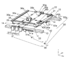
도 1은 제1의 실시의 형태와 관련되는 노광 장치(1)의 개략을 나타내는 사시도이다.
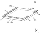
도 2는 마스크 보유부(20)의 개략을 나타내는 사시도이다.
도 3은 템플릿 보유부(24) 및 템플릿(25)에 대해 설명하는 도이다.
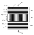
도 4는 템플릿(25)의 상면(25a)의 부분 확대도이다.
도 5는 1매의 마스크로부터 템플릿(25)이 복수 작성되는 모습을 모식적으로 나타내는 도이다.
도 6은 광 조사부(30a)의 개략을 나타내는 주요부 투시도이다.
도 7은 측정부(40) 및 레이저 간섭계(50)가 마스크 보유부(20)의 위치를 측정하는 모습을 나타내는 개략도이다.
도 8은 노광 장치(1)의 전기적인 구성을 나타내는 블록도이다.
도 9는 제어부(151a)가 행하는 구동부(61, 62)의 제어에 대해 설명하는 도이다.
도 10은 광 조사부(30a~30g)가 템플릿(25)의 상을 통과할 때에 광 조사부(30a~30g)로부터 각각 조사되는 광(이하, 검사용 패턴이라고 함)을 나타내는 도이다.
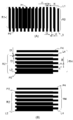
도 11은 촬상 소자(18x)에 결상된 화상의 일부를 예시하는 도이며, (A)는 패턴 P1과 패턴 P3이 겹친 부분의 화상의 일례이며, (B)는 패턴 P2와 패턴 P4가 겹친 부분의 화상의 일례이다.
도 12는 제어부(151a)가 행하는 묘화 위치 보정 처리에 대해 설명하는 도이다. 1 is a perspective view showing an outline of an
2 is a perspective view schematically showing the
3 is a diagram for explaining the
4 is a partially enlarged view of the
5 is a diagram schematically showing how a plurality of
6 is a perspective view of a main part showing an outline of the
7 is a schematic view showing a state in which the
8 is a block diagram showing the electrical configuration of the
9 is a diagram for explaining control of the
10 is a view showing light (hereinafter, referred to as an inspection pattern) irradiated from the
11 is a diagram illustrating a part of an image formed on the imaging element 18x, (A) is an example of an image of a portion where pattern P1 and pattern P3 overlap, and (B) is a portion where pattern P2 and pattern P4 overlap. It is an example of an image.
12 is a diagram for explaining a drawing position correction process performed by the
이하, 본 발명의 실시 형태를 도면을 참조하여 상세하게 설명한다. 각 도면에 있어서, 동일한 요소에는 동일한 부호를 붙이고 중복된 부분에 대해서는 설명을 생략한다. Hereinafter, embodiments of the present invention will be described in detail with reference to the drawings. In each drawing, the same reference numerals are assigned to the same elements, and descriptions of overlapping parts are omitted.
본 발명에 있어서의 노광 장치는, 대략 수평 방향으로 유지한 감광성 기판(예를 들면, 유리 기판)을 주사 방향으로 이동시키면서 레이저 등의 광을 조사하여 포토마스크(photomask)를 생성하는 마스크 제조 장치이다. 감광성 기판으로서는, 예를 들면 열팽창율이 매우 작은(예를 들면, 약 5.5x10⁻⁷/K 정도) 석영 유리가 이용된다.The exposure apparatus in the present invention is a mask manufacturing apparatus that generates a photomask by irradiating light such as a laser while moving a photosensitive substrate (for example, a glass substrate) held in a substantially horizontal direction in the scanning direction. . As the photosensitive substrate, quartz glass having a very small thermal expansion coefficient (for example, about 5.5x10 -7 / K) is used.
노광 장치에 의해 생성되는 포토마스크는, 예를 들면 액정표시장치용의 기판을 제조하기 위해서 이용되는 노광용 마스크이다. 포토마스크는, 한 변이 예를 들면 1m를 넘는(예를 들면, 1400㎜x1220㎜) 대형의 대략 직사각형 형상의 기판 상에, 1개 또는 복수개의 이미지 디바이스용 전사 패턴이 형성된 것이다. 이하, 가공전, 가공중 및 가공후의 감광성 기판(포토마스크)을 포괄하는 개념으로서 마스크 M이라고 하는 용어를 사용한다. The photomask produced by the exposure apparatus is, for example, an exposure mask used for manufacturing a substrate for a liquid crystal display device. In a photomask, a transfer pattern for one or a plurality of image devices is formed on a large, substantially rectangular substrate having one side of, for example, more than 1 m (for example, 1400 mm × 1220 mm). Hereinafter, the term mask M is used as a concept encompassing photosensitive substrates (photomasks) before, during, and after processing.
다만, 본 발명의 노광 장치는, 마스크 제조 장치에 한정되지 않는다. 본 발명의 노광 장치는, 대략 수평 방향으로 유지한 기판을 주사 방향으로 이동시키면서 광(레이저, UV(UltraViolet), 편광 광 등을 포함)을 조사하는 여러 가지 장치를 포함하는 개념이다. However, the exposure apparatus of the present invention is not limited to the mask manufacturing apparatus. The exposure apparatus of the present invention is a concept including various apparatuses that irradiate light (including laser, UV (UltraViolet), polarized light, etc.) while moving a substrate held in a substantially horizontal direction in a scanning direction.
도 1은 제1의 실시의 형태와 관련되는 노광 장치(1)의 개략을 나타내는 사시도이다. 노광 장치(1)는, 주로 정반(11)과, 판상부(12)와, 레일(13, 14)과, 프레임체(frame body)(15)와, 마스크 보유부(20)와, 광 조사부(30)와, 측정부(40)와, 레이저 간섭계(50)를 가진다. 또한, 도 1에 있어서는, 일부의 구성에 대해 도시를 생략하고 있다. 또, 노광 장치(1)는, 장치 전체를 덮는 도시하지 않는 온도 조정부에 의해 일정 온도로 유지되어 있다. 1 is a perspective view showing an outline of an
정반(11)은, 대략 직방체 형상(두꺼운 판 형상)의 부재이며, 예를 들면 돌(예를 들면, 화강암)이나 낮은 팽창율의 주물(예를 들면, 니켈계의 합금)로 형성된다. 정반(11)은, 상측(+z측)에 대략 수평(xy평면과 대략 평행)인 상면(11a)을 가진다. The
정반(11)은, 설치면(예를 들면, 상(床)) 상에 재치된 복수의 제진대(도시하지 않음)의 상에 재치된다. 이에 의해 정반(11)이 제진대(除振臺)를 통해 설치면 상에 재치된다. 제진대는 이미 공지이기 때문에 상세한 설명을 생략한다. 또한, 제진대는 필수는 아니다. 정반(11)의 +x측에는, 마스크 M을 마스크 보유부(20)에 설치하는 로더(loader)(도시하지 않음)가 설치된다. The
레일(13)은, 세라믹제의 가늘고 긴 판상의 부재이며, 정반(11)의 상면(11a)에, 긴 방향이 x방향을 따르도록 고정된다. 3개의 레일(13)은, 높이(z방향의 위치)가 대략 동일하고, 상면이 높은 정밀도 및 높은 평탄도로 형성된다. The
로더(loader)측(+x측)의 레일(13)은, 단(端)이 상면(11a)의 단부에 설치되고, 반(反)로더(loader)측(-x측)의 레일(13)은, 단(端)이 상면(11a)의 단부보다 내측에 설치된다. The
판상부(12)는, 레일(13)의 상에 재치된다. 판상부(12)는, 세라믹제의 대략 판상의 부재이며, 전체적으로 대략 직사각형 형상이다. 판상부(12)의 하면(-z측의 면)에는, 긴 방향이 x방향을 따르도록 가이드부(도시하지 않음)가 설치된다. 이에 의해 판상부(12)가 x방향 이외에 이동하지 않게 판상부(12)의 이동 방향이 규제된다. The plate-shaped
판상부(12)의 상면(12a)에는, 레일(14)이 설치된다. 레일(14)은, 긴 방향이 y방향을 따르도록 고정된다. 레일(14)은, 높이가 대략 동일하고, 상면이 높은 정밀도 및 높은 평탄도로 형성된다. A
마스크 보유부(20)는, 평면시 대략 직사각형 형상의 대략 판상이며, 열팽창 계수가 대략 0.5~1x10⁻⁷/K의 낮은 팽창성 세라믹을 이용하여 형성된다. 이에 의해 마스크 보유부(20)의 변형을 방지할 수가 있다. 또한, 마스크 보유부(20)는, 열팽창 계수가 대략 5x10⁻⁸/K의 매우 낮은 팽창성 유리 세라믹을 이용하여 형성할 수도 있다. 이 경우에는, 제어할 수 없는 온도 변화가 발생하였다고 해도, 마스크 보유부(20)의 변형을 확실하게 방지할 수가 있다. 또한, 마스크 보유부(20)를 마스크 M과 마찬가지로 신축하는 재료로 형성해도 좋다. The
마스크 보유부(20)는, 레일(14)의 상에 재치된다. 바꾸어 말하면, 마스크 보유부(20)는, 판상부(12) 및 레일(13, 14)을 통해 상면(11a)에 설치된다. The
마스크 보유부(20)의 하면에는, 긴 방향이 y방향을 따르도록 가이드부(도시하지 않음)가 설치된다. 이에 의해 마스크 보유부(20), 즉 판상부(12)가 y방향 이외에 이동하지 않게 마스크 보유부(20)의 이동 방향이 규제된다. On the lower surface of the
이와 같이 마스크 보유부(20)(판상부(12))는, 레일(13)을 따라 x방향으로 이동 가능하게 설치되고, 마스크 보유부(20)는, 레일(14)을 따라 y방향으로 이동 가능하게 설치된다. Thus, the mask holding part 20 (plate-shaped part 12) is movably installed along the
마스크 보유부(20)는, 대략 수평인 상면(20a)을 가진다. 상면(20a)에는, 마스크 M(도시 생략)이 재치된다. 마스크 보유부(20)의 상세한 것에 대해서는 후에 상술한다. The
노광 장치(1)는, 도시하지 않는 구동부(61, 62)(도 1에서는 도시하지 않음, 도 8 참조)를 가진다. 구동부(61, 62)는, 예를 들면 리니어 모터(linear motor)이다. 구동부(61)는 마스크 보유부(20)(판상부(12))을 레일(13)을 따라 x방향으로 이동시키고, 구동부(62)는 마스크 보유부(20)를 레일(14)을 따라 y방향으로 이동시킨다. 구동부(61, 62)가 판상부(12)나 마스크 보유부(20)를 이동시키는 방법은, 이미 공지의 여러 가지 방법을 이용할 수가 있다. The
측정부(40)(도 1에서는 도시 생략, 도 7 참조)는, 예를 들면 리니어 엔코더(encoder)이며, 마스크 보유부(20)의 위치를 측정한다. 측정부(40)는, 위치 측정부(41, 42)를 가진다. 측정부(40)에 대해서는 후에 상술한다. The measurement unit 40 (not shown in FIG. 1 and see FIG. 7) is, for example, a linear encoder, and measures the position of the
정반(11)에는, 프레임체(15)가 설치된다. 프레임체(15)는, 마스크 보유부(20)의 상방(+z방향)에 광 조사부(30)를 보유한다. The frame body 15 is provided on the
광 조사부(30)는, 마스크 M에 광(본 실시의 형태에서는, 레이저 광)을 조사한다. 광 조사부(30)는, y방향을 따라 일정 간격(예를 들면, 대략 200㎜ 띄워서)으로 설치된다. 본 실시의 형태에서는, 7개의 광 조사부(30a), 광 조사부(30b), 광 조사부(30c), 광 조사부(30d), 광 조사부(30e), 광 조사부(30f), 광 조사부(30g)를 가진다. 광 조사부(30a~30g)는, 각각 도시하지 않는 구동부에 의해, z방향으로 이동 가능하게 설치된다. 광 조사부(30a~30g)전체를 10㎜ 정도의 범위에서 조동(粗動)시키는 조동축(粗動軸)(도시하지 않음)과, 광 조사부(30a~30g)를 30㎛ 정도의 범위에서 미동(微動)시키는 미동축(微動軸)(도시하지 않음)을 가진다. 광 조사부(30)에 대해서는 후에 상술한다. The
레이저 간섭계(50)는, 레이저 간섭계(51, 52)를 가진다. 프레임체(15)의 -y측에 설치된 기둥에는, 레이저 간섭계(51)가 설치된다. 또, 정반(11)의 +x측의 측면에는, 레이저 간섭계(52)(도 1에서는 도시 생략)가 설치된다. 레이저 간섭계(50)에 대해서는 후에 상술한다. The
다음에, 마스크 보유부(20)에 대해 설명한다. 도 2는 마스크 보유부(20)의 개략을 나타내는 사시도이다. Next, the
마스크 보유부(20)는, 상면(20a)과 인접하는 측면(20b, 20c, 20d)를 가진다. 측면(20d)은 측면(20b)의 반대측의 면이다. 측면(20b)은 +x측의 측면이며, 측면(20c)은 -y측의 측면이며, 측면(20d)은 -x측의 측면이다. 측면(20b, 20d)은, x방향과 대략 직교하고 있고(y방향을 대략 따르고 있고), 측면(20c)은 x방향을 대략 따르고 있다. 측면(20b, 20c, 20d)은, z방향과 대략 평행이다. The
상면(20a)에는, 막대 미러(21, 22, 23)가 설치된다. 막대 미러(21, 22)는, 측면(20b)을 따라 설치되고, 막대 미러(23)는, -y측의 측면(20c)을 따라 설치된다. Bar mirrors 21, 22, and 23 are provided on the
측면(20d)에는, 템플릿 보유부(24)가 설치된다. 템플릿 보유부(24)에는, 템플릿(25)이 설치된다. On the
도 3은 템플릿 보유부(24) 및 템플릿(25)에 대해 설명하는 도이다. 템플릿 보유부(24)는, 투명한 재료(예를 들면, 석영 유리)로 형성되고, z방향과 대략 평행 방향으로 이동 가능하게 설치된다. 템플릿 보유부(24)를 석영 유리로 함으로써, 템플릿(25)의 열팽창에 의한 왜곡을 최소로 할 수가 있다. 3 is a diagram for explaining the
템플릿 보유부(24)의 상측의 면(24a)에는, 템플릿(25)이 설치되는 오목부(24b)가 형성된다. 오목부(24b)와 템플릿(25)의 사이에는, 탄성을 가지는 투명한 수지 재료(26)가 충전된다. 이에 의해 템플릿(25)을 오목부(24b)에 접착하면서 온도 등의 변화에 의한 왜곡을 방지할 수가 있다. 수지 재료(26)가 충전되는 공간의 두께는, 도 3에 있어서의 좌우 방향, 높이 방향 모두 대략 동일하게 한다. On the
마스크 보유부(20)에는, 구동부(63)(도 3에서는 도시하지 않음, 도 8 참조)가 설치된다. 구동부(63)는, 템플릿 보유부(24)를 z방향(도 3의 화살표 방향)으로 이동시킨다. 또, 템플릿 보유부(24)는, 측면(20d)에 대해, 도시하지 않는 진공 흡착 기구 또는 마찰력에 의해 고정된다. 구동부(63)나 진공 흡착 기구는, 이미 공지의 여러 가지 방법을 이용할 수가 있다. The
구동부(63)는, 마스크 보유부(20)의 상면(20a)에 재치된 마스크 M의 상면 Ma와, 템플릿(25)의 상면(25a)가 대략 일치(여기서, 대략 일치란, 대략 ±30㎛ 이내인 것)하도록, 템플릿 보유부(24)를 측면(20d)과 대략 평행 방향으로 이동시킨다. 템플릿 보유부(24)는, 마스크 M의 종류에 의한 두께의 차이분 (10㎜ 정도)만 z방향으로 이동 가능하게 설치되는 것이 바람직하다. In the driving
템플릿(25)은, 상면(25a)가 상측으로 노출하도록 템플릿 보유부(24)에 설치된다. 도 4는 템플릿(25)의 상면(25a)의 부분 확대도이다. The
상면(25a)에는, x방향을 대략 따른 선 L1이, 선 L1의 폭과 대략 동일한 간격으로 배치된 줄무늬 형상의 패턴 P1이 형성된 영역 R1과, y방향을 대략 따른 선 L2가, 선 L2의 폭과 대략 동일한 간격으로 배치된 줄무늬 형상의 패턴 P2가 형성된 영역 R2가 형성된다. 영역 R1과 영역 R2는, x방향으로 인접하여 형성되고, x방향을 따라 보았을 때에 영역 R1의 양측에 영역 R2가 설치된다. 영역 R1, R2의 x방향의 길이는 대략 300㎛이다. On the
영역 R1은, 템플릿(25)의 x방향 대략 중앙에 설치된다. 템플릿(25)의 x방향 대략 중앙은, 만일 템플릿(25)에 굽음이 발생하였다고 해도 신축이 없는(또는 가장 적은) 부분이다. 이와 같이 영역 R1, R2를 배치함으로써, 모아레 줄무늬를 촬상하는(후에 상술) 처리를 마스크 보유부(20)가 정지한 상태로 행하는 경우에 있어서도, +x측의 영역 R2와 -x측의 영역 R2로 보완함으로써 광 조사부(30)의 대물 렌즈(32)의 대칭 왜곡 성분을 상쇄(cancel)할 수가 있다. The region R1 is provided approximately in the center of the x direction of the
패턴 P1은, 광 조사부(30a~30g)의 y방향의 위치를 결정하기 위한 패턴이며, 패턴 P2는, 광 조사부(30a~30g)로부터 마스크 M에 광을 조사하는 타이밍을 결정하기 위한 패턴이다. 선 L1, L2의 폭 l1, l2는 대략 1~2㎛이다. The pattern P1 is a pattern for determining the position in the y direction of the
패턴 P1, P2의 외측에는, 십자 패턴 P5가 형성된다. 십자 패턴 P5는, 광 조사부(30a~30g)의 y방향의 간격과 대략 동일한 간격으로 형성된다. Cross patterns P5 are formed outside the patterns P1 and P2. The cross pattern P5 is formed at an interval substantially equal to the interval in the y direction of the
템플릿(25)은, 도 5에 나타내듯이, 1매의 마스크(감광성 기판)로부터 복수 작성된다. 마스크는 예를 들면 폭 1400㎜x1220㎜ 정도의 크기이며, 마스크 상에 띠모양의 영역 R1, R2를 복수 형성하고, 이것을 중심으로 한 소정의 폭(예를 들면, 50㎜)으로 마스크를 절단함으로써 템플릿(25)이 형성된다. 템플릿(25)은 마스크 M과 같은 재질이기 때문에, 비록 환경 온도가 변화하여 마스크 M이 열팽창 또는 열수축 하였다고 해도, 템플릿(25)도 같은 양만큼 팽창 또는 수축하기 때문에, 온도 변화에 의한 불편을 최소한으로 할 수 있다. As shown in Fig. 5, a plurality of
도 3의 설명으로 되돌아간다. 템플릿 보유부(24)에는, 면(24a)과 대향하는 면(24c)에 인접하여 렌즈(27)가 설치된다. 도 3의 2점 쇄선으로 나타내듯이, 템플릿(25)에는 광 조사부(30)(도 3에서는 도시 생략)로부터 광이 조사되고, 템플릿(25) 및 렌즈(27)를 통과한 광은 카메라(18)에 입사한다. Returning to the description of FIG. 3. The
카메라(18)는, 레일(13)(도 3에서는 도시 생략)에 설치된다. 카메라(18)는, z방향으로 이동 가능하게 설치되어 도시하지 않는 구동부에 의해 z방향으로 구동된다. 카메라(18)는, y방향을 따라 7개(카메라(18a~18g), 도 12 참조) 설치된다. The
카메라(18)는, CCD, CMOS 등의 촬상 소자(18x)를 가지고, 템플릿(25) 및 렌즈(27)를 통과한 광을 수광한다. 카메라(18)의 시야는 대략 1㎜x1.2㎜ 정도이며, 촬상 소자(18x)에는 패턴 P1, P2 및 십자 패턴 P5가 모두 결상된다. The
카메라(18) 및 렌즈(27)는, 높은 성능일 필요는 없다. 예를 들면, 광학 왜곡의 유무와는 상관이 없이 촬상 소자(18x)의 해상도는 낮아도 좋다. 이에 대해서는 후에 상술한다. The
다음에, 광 조사부(30)에 대해 설명한다. 광 조사부(30a)~광 조사부(30g)는, 동일한 구성이기 때문에, 이하 광 조사부(30a)에 대해 설명한다. Next, the
도 6은 광 조사부(30a)의 개략을 나타내는 주요부 투시도이다. 광 조사부(30a)는, 주로 DMD(Digital Mirror Device)(31)와, 대물 렌즈(32)와, 광원부(33)와, AF(Auto-Focus) 처리부(34)를 가진다. 6 is a perspective view of a main part showing an outline of the
DMD(31)는, 디지털 미러 디바이스(Digital Mirror Device : DMD)이며, 면상(面狀)의 레이저 광을 조사 가능하다. DMD(31)는, 다수의 가동식의 마이크로 미러(도시 생략)를 가지고, 1매의 마이크로 미러로부터 1화소분의 광이 조사된다. 마이크로 미러는, 크기가 대략 10㎛이며, 2차원 형상으로 배치되어 있다. DMD(31)에는 광원부(33)(후에 상술)로부터 광이 조사되고, 광은 각 마이크로 미러에서 반사된다. 마이크로 미러는, 그 대각선과 대략 평행한 축을 중심으로 회전 가능하고, ON(마스크 M을 향해 광을 반사시킴)과 OFF(마스크 M을 향해 광을 반사시키지 않음)의 변환이 가능하다. DMD(31)는 이미 공지이기 때문에 상세한 설명을 생략한다. The
대물 렌즈(32)는, DMD(31)의 각 마이크로 미러에서 반사된 레이저 광을 마스크 M의 표면에 결상시킨다. 묘화시에는, 광 조사부(30a~30g)의 각각으로부터 광이 조사되고, 이 광이 마스크 M 상에서 결상함으로써, 마스크 M에 패턴이 묘화된다. The
광원부(33)는, 주로 광원(33a)과, 렌즈(33b)와, 플라이 아이 렌즈(fly-eye lens)(33c)와, 렌즈(33d, 33e)와, 미러(33f)를 가진다. 광원(33a)은, 예를 들면 레이저 다이오드이며, 광원(33a)으로부터 출사된 광은 광섬유 등을 통해 렌즈(33b)에 도입된다. The
광은 렌즈(33b)로부터 플라이 아이 렌즈(33c)에 도입된다. 플라이 아이 렌즈(33c)는 복수매의 렌즈(도시하지 않음)를 2차원 형상으로 배치한 것이고, 플라이 아이 렌즈(33c)에 있어서 다수의 점광원이 만들어진다. 플라이 아이 렌즈(33c)를 통과한 광은 렌즈(33d, 33e)(예를 들면, 콘덴서 렌즈)를 거쳐 평행광으로 되고, 미러(33f)에서 DMD(31)를 향해 반사된다. Light is introduced from the
AF 처리부(34)는, 마스크 M에 조사되는 광의 초점을 마스크 M에 맞추는 것이고, 주로 AF용 광원(34a)과, 콜리메이터 렌즈(collimator lens)(34b)와, AF용 실린드리칼 렌즈(cylinderical lens)(34c)와, 미러(34d, 34e)와, 렌즈(34f)와, AF 센서(34g, 34h)를 가진다. AF용 광원(34a)으로부터 조사된 광은 콜리메이터 렌즈(34b)에서 평행광으로 되고, AF용 실린드리칼 렌즈(34c)에서 선상(線狀)의 광으로 되고, 미러(34d)에서 반사되어 마스크 M의 표면에 결상 한다. 마스크 M에서 반사한 광은 미러(34e)에서 반사되고, 렌즈(34f)로 집광되어, AF 센서(34g, 34h)에 입사한다. AF 처리부(34)는, AF 센서(34g, 34h)에서 수광된 결과에 기초하여 촛점 맞춤 위치를 구하는 오토포커스(Auto-Focus) 처리를 행한다. 또한, 오토포커스 처리는 이미 공지이기 때문에 상세한 설명을 생략한다. The
도 7은 측정부(40) 및 레이저 간섭계(50)가 마스크 보유부(20)의 위치를 측정하는 모습을 나타내는 개략도이다. 또한, 도 7에서는, 레일(13, 14)의 일부만 도시하고 있다. 또, 도 7에서는, 광 조사부(30a, 30g)만 도시하고, 광 조사부(30b~30f)에 대해서는 도시를 생략한다. 7 is a schematic view showing a state in which the
위치 측정부(41, 42)는, 각각 스케일(41a, 42a)과, 검출 헤드(41b, 42b)를 가진다. The
스케일(41a)은, +y측의 레일(13)의 +y측의 단면 및 -y측의 레일(13)의 -y측의 단면에 설치된다. 검출 헤드(41b)는, 판상부(12)(도 6에서는 도시 생략)의 +y측 및 -y측의 단면에 설치된다. 도 7에서는, +y측의 스케일(41a) 및 검출 헤드(41b)에 대한 도시를 생략한다. The
스케일(42a)은, +x측의 레일(14)의 +x측의 단면 및 -x측의 레일(13)의 -x측의 단면에 설치된다. 검출 헤드(42b)(도 1에서는 도시 생략)는, 마스크 보유부(20)의 +x측 및 -x측의 단면에 설치된다. 도 7에서는, -x측의 스케일(42a) 및 검출 헤드(42b)에 대한 도시를 생략한다. The
스케일(41a, 42a)은, 예를 들면 레이저 홀로그램 스케일이며, 0.512㎛ 피치로 메모리가 형성되어 있다. 검출 헤드(41b, 42b)는, 광(예를 들면, 레이저 광)을 조사하고, 스케일(41a, 42a)에서 반사된 광을 취득하고, 이에 의해 발생하는 신호를 512 등분하여 1㎚를 얻고, 이에 의해 발생하는 신호를 5120 등분하여 0.1㎚를 얻는다. 위치 측정부(41, 42)는 이미 공지이기 때문에 상세한 설명을 생략한다. The
광 조사부(30a)에는, xz평면과 대략 평행한 반사면을 가지는 미러(35a)가 설치된다. 광 조사부(30g)에는, xz평면과 대략 평행한 반사면을 가지는 미러(35b, 35c)가 설치된다. 미러(35a, 35b, 35c)는, x방향의 위치가 겹치지 않게 설치된다. A
광 조사부(30a)에는, yz평면과 대략 평행한 반사면을 가지는 미러(36a)가 설치된다. 광 조사부(30g)에는, yz평면과 대략 평행한 반사면을 가지는 미러(36g)가 설치된다. The
레이저 간섭계(51, 52)는, 4개의 레이저 광을 조사한다. 레이저 간섭계(51)는, 레이저 간섭계(51a, 51b, 51c)를 가진다. 레이저 간섭계(52)는, 레이저 간섭계(52a, 52g)를 가진다. The
도 7에 있어서, 레이저 광의 경로를 2점 쇄선으로 나타낸다. 레이저 간섭계(51a, 51b, 51c)로부터 조사되는 광 중의 2개는, 막대 미러(23)에서 반사되어, 그 반사광이 레이저 간섭계(51a, 51b, 51c)에서 수광된다. In Fig. 7, the path of the laser light is indicated by a two-dot chain line. Two of the light irradiated from the laser interferometers 51a, 51b, and 51c are reflected by the
레이저 간섭계(51a)로부터 조사되는 광 중의 나머지의 2개는 미러(35a)에서 반사하여, 그 반사광이 레이저 간섭계(51a)에서 수광된다. 레이저 간섭계(51b)로부터 조사되는 광 중의 나머지의 2개는 미러(35b)에서 반사하여, 그 반사광이 레이저 간섭계(51b)에서 수광된다. 레이저 간섭계(51c)로부터 조사되는 광 중의 나머지의 2개는 미러(35c)에서 반사하여, 그 반사광이 레이저 간섭계(51c)에서 수광된다. The other two of the light irradiated from the laser interferometer 51a are reflected by the
레이저 간섭계(51a~51c)는, 각각 미러(35a~35c)의 위치를 기준으로 하여 막대 미러(23)의 위치를 측정함으로써, 광 조사부(30a, 30g)와 마스크 보유부(20)의 y방향의 위치 관계를 측정한다. The laser interferometers 51a to 51c measure the positions of the rod mirrors 23 based on the positions of the
레이저 간섭계(52a)로부터 조사되는 광 중의 2개는, 막대 미러(22)에서 반사되어, 그 반사광이 레이저 간섭계(52a)에서 수광된다. 레이저 간섭계(52g)로부터 조사되는 광 중의 2개는, 막대 미러(21)에서 반사되어, 그 반사광이 레이저 간섭계(52g)에서 수광된다. Two of the light irradiated from the
레이저 간섭계(52a)로부터 조사되는 광 중의 나머지의 2개는 미러(36a)에서 반사하여, 그 반사광이 레이저 간섭계(52a)에서 수광된다. 레이저 간섭계(52g)로부터 조사되는 광 중의 나머지의 2개는 미러(36g)에서 반사하여, 그 반사광이 레이저 간섭계(52g)에서 수광된다. The other two of the light irradiated from the
레이저 간섭계(52a, 52g)는, 각각 미러(36a, 36g)의 위치를 기준으로 하여 막대 미러(21, 22)의 위치를 측정함으로써, 광 조사부(30a~30g)와 마스크 보유부(20)의 x방향의 위치 관계를 측정한다. The
본 실시의 형태에서는, 광 조사부(30b~30f)에는 미러가 설치되지 않고, 그 미러의 위치를 측정하는 레이저 간섭계도 설치되지 않는다. 이것은 광 조사부(30b~30f)의 위치를 광 조사부(30a, 30g)의 위치에 기초하여 내삽(內揷:in terpolation)에 의해 구해지는 것과, 카메라(18)로 촬상되는 모아레 줄무늬를 이용한 보정 처리(후에 상술)에 의해 보정이 가능하기 때문이다. 이에 의해 장치를 소형화할 수가 있고 또한 비용을 내릴 수가 있다. In the present embodiment, no mirror is provided in the
도 8은 노광 장치(1)의 전기적인 구성을 나타내는 블록도이다. 노광 장치(1)는, CPU(Central Processing Unit)(151)와, RAM(Random Access Memory)(152)과, ROM(Read Only Memory)(153)과, 입출력 인터페이스(I/F)(154)와, 통신 인터페이스(I/F)(155)와, 미디어 인터페이스(I/F)(156)를 가지고, 이들은 광 조사부(30), 위치 측정부(41, 42), 레이저 간섭계(51, 52), 구동부(61, 62, 63) 등과 서로 접속되어 있다. 8 is a block diagram showing the electrical configuration of the
CPU(151)는, RAM(152), ROM(153)에 격납된 프로그램에 기초하여 동작하고, 각부의 제어를 행한다. CPU(151)에는, 위치 측정부(41, 42), 레이저 간섭계(51, 52) 등으로부터 신호가 입력된다. CPU(151)로부터 출력된 신호는, 구동부(61, 62, 63), 광 조사부(30)로 출력된다. The
RAM(152)은, 휘발성 메모리이다. ROM(153)은, 각종 제어 프로그램 등이 기억되어 있는 불휘발성 메모리이다. CPU(151)는, RAM(152), ROM(153)에 격납된 프로그램에 기초하여 동작하고, 각부의 제어를 행한다. 또, ROM(153)은, 노광 장치(1)의 기동시에 CPU(151)가 행하는 부트(boot) 프로그램이나, 노광 장치(1)의 하드웨어에 의존하는 프로그램, 마스크 M에의 묘화 데이터 등을 격납한다. 또, RAM(152)은, CPU(151)가 실행하는 프로그램 및 CPU(151)가 사용하는 데이터 등을 격납한다. The
CPU(151)는, 입출력 인터페이스(154)를 통해, 키보드나 마우스 등의 입출력 장치(141)를 제어한다. 통신 인터페이스(155)는, 네트워크(142)를 통해 다른 기기로부터 데이터를 수신하여 CPU(151)에 송신함과 아울러, CPU(151)가 생성한 데이터를 네트워크(142)를 통해 다른 기기에 송신한다. The
미디어 인터페이스(156)는, 기억 매체(143)에 격납된 프로그램 또는 데이터를 읽어내고, RAM(152)에 격납한다. 또한, 기억 매체(143)는, 예를 들면 IC 카드, SD 카드, DVD 등이다. The
또한, 각 기능을 실현하는 프로그램은, 예를 들면 기억 매체(143)로부터 읽어내어져, RAM(152)을 통해 노광 장치(1)에 인스톨(install) 되고, CPU(151)에 의해 실행된다. In addition, the program for realizing each function is read from the storage medium 143, for example, is installed in the
CPU(151)는, 입력 신호에 기초하여 노광 장치(1)의 각부를 제어하는 제어부(151a)의 기능을 가진다. 제어부(151a)는, CPU(151)가 읽어들인 소정의 프로그램을 실행함으로써 구축된다. 제어부(151a)가 행하는 처리에 대해서는 후에 상술한다. The
도 8에 나타내는 노광 장치(1)의 구성은, 본 실시 형태의 특징을 설명하는데 즈음하여 주요 구성을 설명한 것으로서, 예를 들면 일반적인 정보처리 장치가 구비하는 구성을 배제하는 것은 아니다. 노광 장치(1)의 구성 요소는, 처리 내용에 따라 한층 더 많은 구성 요소로 분류되어도 좋고, 1개의 구성 요소가 복수의 구성 요소의 처리를 실행해도 좋다. The configuration of the
이와 같이 구성된 노광 장치(1)의 작용에 대해 설명한다. 이하의 처리는, 주로 제어부(151a)에 의해 행해진다. The operation of the
제어부(151a)는, 묘화 처리에 앞서, 레이저 간섭계(51, 52)를 이용하여 위치 측정부(41, 42)의 교정(calibration)을 행한다. 또, 제어부(151a)는, 구동부(63)를 제어하여 템플릿 보유부(24)를 z방향으로 이동시키고, 마스크 M의 높이와 템플릿(25)의 높이를 일치시킨다. 다음에, 제어부(151a)는, 위치 측정부(41, 42)에서 취득한 측정치에 기초하여, 마스크 보유부(20)를 이동시킨다. The
제어부(151a)는, 위치 측정부(41, 42)의 측정 결과에 기초하여 마스크 보유부(20)를 x방향 및 y방향으로 이동시킨다. 도 9는 제어부(151a)가 행하는 구동부(61, 62)의 제어에 대해 설명하는 도이다. 여기에서는, 구동부(61, 62)가 리니어 모터인 것으로 하여 설명한다. The
우선, 추력 변환부(164, 174)는, 구동부(61, 62)의 가동자의 U상, V상, W상에 각각 신호를 출력하고, 추력 변환부(164, 174)는, 그 결과에 기초하여 가동자의 U상, V상, W상의 역률(역률(力率) 정보)을 구해 둔다. First, the
-y측의 위치 측정부(41)에 있어서의 계측 신호는, X카운터(1)(161)에 입력되고, +y측의 위치 측정부(41)에 있어서의 계측 신호는, X카운터(2)(162)에 입력된다. 제어부(151a)는, X카운터(1)(161)의 출력과 X카운터(2)(162)의 출력의 평균치를 현재 위치로 한다. The measurement signal from the
-x측의 위치 측정부(42)에 있어서의 계측 신호는, Y카운터(1)(171)에 입력되고, +x측의 위치 측정부(42)에 있어서의 계측 신호는, Y카운터(2)(172)에 입력된다. 제어부(151a)는, Y카운터(1)(171)의 출력과 Y카운터(2)(172)의 출력의 평균치를 현재 위치로 한다. -The measurement signal from the
목표 좌표 산출부(163, 173)에서는, 각각 CPU(151)로부터 출력되는 펄스 등에 기초하여, 현시점에 있어서의 목표 좌표(위치 지령)가 산출된다. 제어부(151a)는, X카운터(1)(161), X카운터(2)(162)로부터의 출력 신호와 목표 좌표 산출부(163)로부터 출력된 위치 지령과의 편차의 일차 함수(P)를 산출한다. 또, 제어부(151a)는, 편차의 적분에 비례하여 변화하는 입력치(I)와 편차의 미분에 비례하여 변화하는 입력치(D)를 산출한다. 이들 값은, 추력 변환부(164)에 입력된다. 제어부(151a)는, Y카운터(1)(171), Y카운터(2)(172)로부터의 출력 신호와 목표 좌표 산출부(173)로부터 출력된 위치 지령과의 편차의 일차 함수(P)를 산출한다. 또, 제어부(151a)는, 편차의 적분에 비례하여 변화하는 입력치(I)와 편차의 미분에 비례하여 변화하는 입력치(D)를 산출한다. 이들 값은, 추력 변환부(174)에 입력된다. The target coordinate
또한, 제어부(151a)는, 목표 좌표 산출부(163, 173)에서 각각 산출된 위치 지령을 1차 미분하는 1차 미분항과 위치 지령을 2차 미분하는 2차 미분항을 산출하고, 각각 추력 변환부(164, 174)에 입력한다. 추력 변환부(164, 174)에는, 각각 원점 센서(165, 175)로부터 구동부(61, 62)의 위치를 관리하기 위해서 기준이 되는 원점 신호가 입력된다. In addition, the
추력 변환부(164, 174)는, 각각 입력된 정보에 기초하여 구동부(61, 62)를 구동하기 위한 신호를 생성한다. 구체적으로는, 추력 변환부(164, 174)는, 비례 동작, 적분 동작, 미분 동작을 조합한 PID 제어와, 목표 좌표 산출부(163, 173)로부터 입력된 위치 지령, 1차 미분항, 2차 미분항에 기초한 피드포워드(feed-forward) 제어를 행한다. 그리고, 추력 변환부(164, 174)에서는, 제어 결과, 역률 정보 등에 기초하여 구동 신호를 생성한다. 구동 신호는, U상, V상, W상의 각각 대응하는 신호이며, 증폭기(amplifier)에서 각각 증폭된 후, 가동자의 U상, V상, W상의 코일 각각에 출력된다. 따라서, 마스크 보유부(20)를 정확하게 이동시킬 수가 있다. 또한, 정밀도가 높은 제어(㎚~수십㎚ 단위의 제어)를 행하기 위해서는, 증폭기는, DC(Direct Current) 리니어 증폭기인 것이 바람직하다. The
제어부(151a)는, 이와 같이 하여 마스크 보유부(20)를 이동시키면서, 광 조사부(30)의 하측을 마스크 M이 통과할 때에 광 조사부(30)로부터 광을 조사하여 묘화 처리를 행한다. The
이 묘화 처리에 있어서, 제어부(151a)는, 광 조사부(30)의 하측에 템플릿(25)이 위치할 때에, 광 조사부(30)로부터 템플릿(25)을 향해 광을 조사하고, 광 조사부(30)의 x방향 및 y방향의 위치 어긋남을 취득한다. 이하, 광 조사부(30)의 x방향 및 y방향의 위치 어긋남의 취득 방법에 대해 설명한다. 당해 처리는, 제어부(151a)가 구동부(61, 62)에 의해 마스크 보유부(20)를 이동시키면서 행해진다. In this drawing process, the
도 10은 광 조사부(30a~30g)가 템플릿(25)의 상을 통과할 때에 광 조사부(30a~30g)로부터 각각 조사되는 광(이하, 검사용 패턴이라고 함)을 나타내는 도이다. 검사용 패턴은, x방향을 따른 선 L3이, 선 L3의 폭과 대략 동일한 간격으로 배치된 줄무늬 형상의 패턴 P3을 가지는 영역 R3과, y방향을 따른 선 L4가, 선 L4의 폭과 대략 동일한 간격으로 배치된 줄무늬 형상의 패턴 P4가 형성된 영역 R4를 가진다. 영역 R3과 영역 R4는, x방향으로 인접하여 형성되고, x방향을 따라 보았을 때에 영역 R3의 양측에 영역 R4가 설치된다. 선 L3, L4의 폭 l3, l4는, 각각 선 L1, L2의 폭 l1, l2보다 굵다. 또, 광 조사부(30a~30g)로부터는, 십자 패턴 P6이 조사된다. 10 is a view showing light (hereinafter, referred to as an inspection pattern) irradiated from the
검사용 패턴은, 템플릿(25) 등을 통과하여 카메라(18)의 촬상 소자(18x)에 결상된다. 카메라(18a~18g)(도 12 참조)에서는, 각각 광 조사부(30a~30g)로부터 조사된 패턴 P3, P4, P6과 템플릿(25)에 형성된 패턴 P1, P2, P5가 겹쳐진 화상을 읽어낸다. The inspection pattern passes through the
도 11은 촬상 소자(18x)에 결상된 화상의 일부를 예시하는 도이며, (A)는 패턴 P1과 패턴 P3이 겹친 부분의 화상의 일례이며, (B)는 패턴 P2와 패턴 P4가 겹친 부분의 화상의 일례이다. 또한, 도 11에서는 설명을 위해 패턴 P1과 패턴 P3을 비켜 놓고, 패턴 P2와 패턴 P4를 비켜 놓아 도시하고 있다. 11 is a diagram illustrating a part of an image formed on the imaging element 18x, (A) is an example of an image of a portion where pattern P1 and pattern P3 overlap, and (B) is a portion where pattern P2 and pattern P4 overlap. It is an example of an image. 11, the pattern P1 and the pattern P3 are set aside for illustration, and the pattern P2 and the pattern P4 are set aside.
선 L3의 폭 l3이 선 L1의 폭 l1보다 굵고, 선 L3 사이의 간격(폭 l3과 대략 동일)이 선 L1 사이의 간격(폭 l1과 대략 동일)보다 넓기 때문에, 도 11(A)에 나타내듯이, 촬상 소자(18x)에는 모아레 줄무늬가 결상된다. 제어부(151a)는, 패턴 P1, P3에 의해 형성된 모아레 줄무늬의 검은색의 피크 위치, 흰색의 피크 위치나 모아레 줄무늬의 위상을 검출함으로써, 광 조사부(30a~30g)의 y방향의 위치 어긋남을 취득한다. Since the width l3 of the line L3 is larger than the width l1 of the line L1, and the spacing between the lines L3 (approximately equal to the width l3) is larger than the spacing between the lines L1 (approximately the same as the width l1), it is shown in Fig. 11 (A). As such, moire streaks are formed on the imaging element 18x. The
선 L4의 폭 l4가 선 L2의 폭 l2보다 굵고, 선 L4간의 간격(폭 l4와 대략 동일)이 선 L2간의 간격(폭 l2와 대략 동일)보다 넓기 때문에, 도 11(B)에 나타내듯이, 촬상 소자(18x)에는 모아레 줄무늬가 결상된다. 제어부(151a)는, 패턴 P2, P4에 의해 형성된 모아레 줄무늬의 검은색의 피크 위치, 흰색의 피크 위치나 모아레 줄무늬의 위상을 검출함으로써, 광 조사부(30a~30g)의 x방향의 위치 어긋남을 취득한다. As the width l4 of the line L4 is larger than the width l2 of the line L2, and the spacing between the lines L4 (approximately equal to the width l4) is wider than the spacing between the lines L2 (approximately the same as the width l2), as shown in Fig. 11 (B), Moire stripes are formed on the imaging element 18x. The
또한, 본 실시의 형태에서는, 선 L3, L4의 폭 l3, l4가 각각 선 L1, L2의 폭 l1, l2보다 굵고, 선 L3, L4간의 간격이 선 L1, L2간의 간격보다 넓지만, 선 L3, L4의 폭 l3, l4가 각각 선 L, L21의 폭 l1, l2보다 가늘고, 선 L3, L4간의 간격이 선 L1, L2간의 간격보다 좁아도 좋다. 이 경우에도, 촬상 소자(18x)에는 모아레 줄무늬가 결상된다. Further, in the present embodiment, the widths l3 and l4 of the lines L3 and L4 are larger than the widths l1 and l2 of the lines L1 and L2, respectively, and the space between the lines L3 and L4 is wider than the space between the lines L1 and L2, but the line L3 , The widths l3 and l4 of L4 may be thinner than the widths l1 and l2 of the lines L and L21, respectively, and the spacing between the lines L3 and L4 may be narrower than the spacing between the lines L1 and L2. Also in this case, moire stripes are formed on the imaging element 18x.
영역 R1, R3은 y방향을 따라 연속하고 있기 때문에, 촬상 소자(18x)에서 읽어내어지는 모아레 줄무늬에는 검은색의 피크 위치, 흰색의 피크 위치가 복수 포함된다. 그렇지만, 영역 R2, R4는 x방향의 폭이 좁기 때문에, 영역 R2, R4가 1개의 경우에는 검은색의 피크 위치, 흰색의 피크 위치가 복수 포함되지 않을 우려가 있다. 본 실시의 형태에서는, x방향을 따라 보았을 때에 영역 R1, R3의 양측에 설치되기 때문에, 영역 R1, R3의 +x측에 배치된 영역 R2, R4에 의한 모아레 줄무늬와 영역 R1, R3의 -x측에 배치된 영역 R2, R4에 의한 모아레 줄무늬를 맞춤(필요에 따라서 영역 R2, R4간을 보완함)으로써 검은색의 피크 위치, 흰색의 피크 위치를 복수 검출할 수가 있고, 이에 의해 광 조사부(30a~30g)의 x방향의 위치 어긋남을 정확하게 취득할 수가 있다. Since the regions R1 and R3 are continuous along the y-direction, the moire stripes read out from the imaging element 18x include a plurality of black peak positions and white peak positions. However, since the widths in the x-direction of the regions R2 and R4 are narrow, there is a concern that a plurality of black peak locations and white peak locations may not be included when the regions R2 and R4 are one. In this embodiment, since it is provided on both sides of the regions R1 and R3 when viewed along the x direction, the moiré stripes by the regions R2 and R4 arranged on the + x side of the regions R1 and R3 and -x of the regions R1 and R3 By aligning the moiré stripes by the regions R2 and R4 arranged on the side (compensating between the regions R2 and R4 as necessary), a plurality of black peak positions and white peak positions can be detected, thereby allowing the light irradiation unit ( The positional deviation in the x direction of 30a to 30g) can be accurately obtained.
본 실시의 형태에서는, 모아레 줄무늬를 이용하기 때문에, 선 L1, L2가 읽어내기 불가능한 카메라(18)를 이용하였다고 해도, 선 L1, L2의 폭의 수백분의 일의 정밀도로 위치 어긋남을 취득할 수가 있다(구체적으로는, 선 L1, L2가 대략 1㎛, 위치 어긋남의 취득 정밀도는 대략 1㎚). 또, 모아레 줄무늬가 읽어내기 가능하면, 렌즈(27)에 광학 왜곡이 있어도 문제는 없다. In this embodiment, since the moiré stripes are used, even if the
또한, 십자 패턴 P5, P6에 대해서는 모아레 줄무늬는 아니고, 십자 패턴 P5와 십자 패턴 P6이 동시에 카메라(18)에 결상된다. 이에 의해 광 조사부(30a~30g)의 큰 위치 어긋남(예를 들면, 광 조사부(30b)가 광 조사부(30a)의 y방향 바로 옆에서 일정 간격의 위치에 있는 등)을 취득할 수가 있다. In addition, the cross patterns P5 and P6 are not moire stripes, and the cross pattern P5 and the cross pattern P6 are imaged on the
이와 같이 하여 광 조사부(30a~30g)의 각각에 대해 x방향 및 y방향의 위치 어긋남을 취득한 후에, 제어부(151a)는, 위치 어긋남을 보정하도록 광 조사부(30a~30g)로부터 마스크 M에 광을 조사한다. 구체적으로는, 제어부(151a)는, 패턴 P2, P4에 의한 모아레 줄무늬의 계측 결과로부터 x방향의 오프셋(offset) 값을 조정하여, 광 조사부(30a~30g)에 광을 조사하는 신호(수평 동기 신호)의 타이밍을 변경함으로써 x방향의 위치 어긋남을 보정한다. 또, 제어부(151a)는, 패턴 P1, P3에 의한 모아레 줄무늬의 계측 결과로부터 y방향의 오프셋(offset) 값을 조정하여, 묘화 데이터를 위치 어긋남분만큼 y방향으로 이동시킴으로써 y방향의 위치 어긋남을 보정한다. After obtaining the positional deviation in the x direction and the y direction for each of the
여기서, 묘화 처리에 대해 제어부(151a)가 행하는 광 조사부(30)의 제어에 대해 설명한다. 도 12는 제어부(151a)가 행하는 묘화 위치 보정 처리에 대해 설명하는 도이다. Here, the control of the
위치 측정부(41, 42)의 측정 결과와 레이저 간섭계(52)의 측정 결과는, LUT(181a~187a)에 입력된다. LUT(181a)에 대해서는 레이저 간섭계(52a)의 측정 결과에 기초하여, LUT(187a)에 대해서는 레이저 간섭계(52g)의 측정 결과에 기초한다. LUT(182a~186a)에 대해서는 레이저 간섭계(52a, 52g)의 측정 결과에 기초하여 내삽(內揷)에 의해 산출한다. The measurement result of the
제어부(151a)는, 레이저 간섭계(51, 52)에 있어서의 측정 결과에 기초하여 각 광 조사부(30a~30g)의 LUT(181a~187a)를 산출한다. 또한, LUT(181a~187a)는, 위치 측정부(41, 42)와 레이저 간섭계(51, 52)의 계측차가 변화하지 않는 한 정상치이다. 또, LUT(181a~187a)는, 광 조사부(30a~30g)의 위치마다 xy좌표에 대응하여 값이 2차원 형상으로 배치된 것이다. The
이와 같이 위치 측정부(41, 42)의 측정 결과를 레이저 간섭계(51, 52)를 이용하여 보정한다. 공기 중에서 레이저 간섭계(51, 52)를 이용하면, 아무래도 10㎚ 가까이의 요동이 나와 버린다. 그에 대해 위치 측정부(41, 42)에서는 요동은 발생하지 않는다. 이와 같이 2종류의 방법의 측정 결과에 기초하여 LUT(181a~187a)를 이용한 보정을 행함으로써, 정밀도를 향상시킬 수가 있다. As described above, the measurement results of the
제어부(151a)는, 추력 변환부(164, 174)에 있어서 생성된 구동 신호에 기초하여 구동부(61, 62)를 구동하면서, 위치 측정부(41, 42)에 의해 마스크 보유부(20)의 x방향의 위치 및 마스크 보유부(20)의 y방향의 위치를 측정한다. 그리고, 이들 값을 각 광 조사부(30a~30g)의 위치에 따라 가중 가산하여, 현시점에 있어서의 광 조사부(30a~30g)의 x방향의 위치(191~197) 및 현시점에 있어서의 광 조사부(30a)의 y방향의 위치(198)를 산출한다. 가중 가산에 의한 위치(191~198)의 산출은, 위치 측정부(41, 42)가 광 조사부(30a~30g)의 위치에 있는 것으로 가정했을 때의 측정치의 산출과 마찬가지의 방법으로 행한다. 또한, 위치 측정부(41, 42)의 측정치는 각각 요(yaw) 변위량을 포함하기 때문에, y방향의 위치(198)는, 위치 측정부(41, 42)의 측정치로부터 구해진 회전량을 더하여 산출할 필요가 있다. The
카메라(18a~18g)로 계측된 모아레 줄무늬는, 각각 화상 처리 회로(190a~190g)에서 해석된다. 화상 처리 회로(190a~190g)에서의 해석 결과는, 각각 Ofs(181b~187b, 181c~187c)에 입력된다. Ofs(181b~187b)는, 각각 화상 처리 회로(190a~190g)에 있어서의 주사 노광마다의 패턴 P2, P4에 기초한 모아레 줄무늬의 해석 결과로부터 오프셋(offset) 값을 산출하고, Ofs(181c~187c)는, 각각 화상 처리 회로(190a~190g)에 있어서의 주사 노광마다의 패턴 P1, P3에 기초한 모아레 줄무늬의 해석 결과로부터 오프셋(offset) 값을 산출한다. Moiré stripes measured by the
제어부(151a)는, 광 조사부(30a)의 x방향의 위치(191)를 취득하면, 이 위치(191)에 있어서의 보정치를 LUT(181a)로부터 취득하고, 이것에 Ofs(181b)의 값을 더한 값을 광 조사부(30a)의 x방향의 패턴 위치 보정량으로서 산출한다. 마찬가지로 제어부(151a)는, 광 조사부(30b~30g)의 x방향의 위치(192~197)에 기초하여, 이 위치(192~197)에 있어서의 보정치를 LUT(182a~187a)로부터 취득하고, 이것에 Ofs(182b~187b)를 더한 값을 광 조사부(30b~30g)의 x방향의 패턴 위치 보정량으로서 각각 산출한다. When the
제어부(151a)는, x방향의 패턴 위치 보정량에 기초하여, 수평 동기 신호(도 12에 있어서의 H Drive)의 타이밍을 보정한다. The
또, 제어부(151a)는, 광 조사부(30a)의 y방향의 위치(198)를 취득하면, 이 위치(191)에 있어서의 보정치를 LUT(188a)로부터 취득하고, 이것에 Ofs(181c)의 값을 더한 값을 광 조사부(30a)의 y방향의 패턴 위치 보정량으로서 산출한다. 마찬가지로 제어부(151a)는, LUT(188a)의 값에 Ofs(182b~187b)의 값을 더한 값을 광 조사부(30b~30g)의 y방향의 패턴 위치 보정량으로서 각각 산출한다. 또한, 위치 측정부(41, 42)와 레이저 간섭계(51, 52)의 계측차가 변화하지 않는 한 LUT(188a)는 정상치이다. Moreover, the
제어부(151a)는, 산출된 x방향의 패턴 위치 보정량 및 y방향의 패턴 위치 보정량을 이용하여 묘화 정보를 보정한다. 제어부(151a)는, 보정 후의 묘화 정보에 기초하여, 광 조사부(30a~30g)의 하에 마스크 M이 온 타이밍에 조사를 개시한다. The
묘화는, 수평 동기 신호가 광 조사부(30a~30g)에 입력된 타이밍에 행해진다. 수평 동기 신호는, 묘화 화소에 대해서 1회 입력된다. Drawing is performed at the timing when the horizontal synchronization signal is input to the
템플릿(25)의 위치로부터 마스크 M의 단의 위치까지의 수평 동기 신호의 수는 미리 정해져 있고, ROM(153)에 기억되어 있다. 제어부(151a)는, 카메라(18)로 촬상된 화상에 기초하여 광 조사부(30a~30g)의 x방향의 위치 어긋남을 취득하고, 취득한 x방향의 위치 어긋남에 기초하여 소정 횟수의 수평 동기 신호를 내는 타이밍을 변경한다. The number of horizontal synchronization signals from the position of the
수평 동기 신호의 카운트의 개시 시점은, 패턴 P2, P4의 중합에 의해 형성된 모아레 줄무늬의 검은색의 피크 위치(흰색의 피크 위치라도 좋음)이다. 예를 들면, 광 조사부(30a)에 있어서의 모아레 줄무늬의 검은색의 피크 위치가 올바른 위치(설계치)에 있으면, 제어부(151a)는, 수평 동기 신호를 통상의 타이밍에 광 조사부(30a)에 입력한다. 또, 예를 들면 광 조사부(30b)에 있어서의 모아레 줄무늬의 검은색의 피크 위치가 올바른 위치보다 ΔX1만큼 -x측으로 어긋나 있으면, 제어부(151a)는, 수평 동기 신호를 통상보다 빠른 타이밍에 광 조사부(30b)에 입력하고, 광 조사부(30a)에 의해 묘화가 개시되는 x방향의 위치보다 ΔX1만큼 -x측으로 어긋난 위치로부터 묘화를 개시한다. The starting point of counting of the horizontal synchronization signal is the black peak position of the moire stripes formed by polymerization of the patterns P2 and P4 (the white peak position may be sufficient). For example, if the black peak position of the moire fringe in the
또한, 소정 횟수의 수평 동기 신호는, 위치 측정부(41) 및 레이저 간섭계(52)의 측정 결과에 기초하여 보정된다. 또, 템플릿(25)으로부터 묘화 개시 위치까지의 수평 동기 신호의 타이밍은, LUT(181a~187a) 및 오프셋(offset) 값(181b~187b)으로부터 산출된 위치 어긋남에 기초하여 보정된다. In addition, the horizontal synchronization signal of a predetermined number of times is corrected based on the measurement results of the
제어부(151a)는, 마스크 보유부(20)를 -x방향으로 이동시키면서 묘화 처리를 행한다. 마스크 보유부(20)가 -x방향의 단(端)으로 이동하고, 일렬분의 묘화가 종료하면, 제어부(151a)는, 마스크 보유부(20)를 +x방향의 단(端)으로 이동시키고, 또한 마스크 보유부(20)를 y방향으로 이동시킨다. 그리고, 제어부(151a)는, 템플릿(25)을 통과한 광의 모아레 줄무늬를 카메라(18)로 읽어냄으로써, 광 조사부(30)의 x방향 및 y방향의 위치 어긋남을 취득하는 처리와, 이 위치 어긋남을 보정한 묘화 처리를 반복한다. 또한 묘화 처리에서는, 묘화 위치의 오차를 작게 하기 위해, 최초의 1행의 묘화 후에, 대략 200㎜ 정도 마스크 보유부(20)를 -y방향으로 움직여서, 근처의 광 조사부(30)가 묘화한 바로 옆에 2행째의 묘화를 행하고, 다음에 마스크 보유부(20)를 +y방향으로 움직여서 1행째의 묘화의 이웃에 3행째의 묘화를 행하고, 다음에 마스크 보유부(20)를 -y방향으로 움직여서 2행째의 옆에 4행째의 묘화를 행한다라고 하는 처리를 반복하고, 마지막에 인접하는 광 조사부(30)의 대략 중간 위치의 행을 묘화한다. The
본 실시의 형태에 의하면, 마스크 보유부(20), 즉 템플릿(25)을 이동시키면서 광 조사부(30)로부터 광을 조사하고, 광 조사부(30)로부터 조사된 패턴과 템플릿(25)에 형성된 패턴이 겹쳐진 화상을 카메라(18)로 읽어냄으로써, 주사 노광에 있어서 마크를 형성한 부품(템플릿(25), 즉 마스크 보유부(20))과 마크를 형성하고 있지 않는 부품(광 조사부(30))과의 위치 관계를 구할 수가 있다. According to this embodiment, light is irradiated from the
또, 이 처리를 광 조사부(30a~30g)마다 행함으로써, 광 조사부(30a~30g)끼리의 위치 어긋남을 보정하여 묘화 처리를 행할 수가 있다. 따라서, 마스크 M에 묘화된 화상에 있어서, 광 조사부(30a)와 광 조사부(30b)의 이음매, 광 조사부(30b)와 광 조사부(30c)의 이음매, 광 조사부(30c)와 광 조사부(30d)의 이음매, 광 조사부(30d)와 광 조사부(30e)의 이음매, 광 조사부(30e)와 광 조사부(30f)의 이음매, 광 조사부(30f)와 광 조사부(30g)의 이음매의 어긋남을 없애어 마스크 M에 깨끗한 묘화를 행할 수가 있다. Moreover, by performing this process for each
또, 본 실시의 형태에 의하면, 템플릿(25)에 형성된 패턴 P1, P2와 광 조사부(30a~30g)로부터 조사되는 패턴 P3, P4의 모아레 줄무늬를 관찰함으로써, 카메라(18)가 패턴 P1, P2 등을 직접 읽을 수 없는 경우에 있어서도, 마스크 보유부(20)와 광 조사부(30a~30g)의 위치 관계를 구할 수가 있다. 따라서, 카메라(18)의 성능이 고도이지 않아도, 나노미터 단위의 정밀도로 광 조사부(30a~30g)의 위치 어긋남을 구할 수가 있다. Further, according to the present embodiment, the
또, 본 실시의 형태에 의하면, 템플릿 보유부(24)를 측면(20d)과 대략 평행 방향으로 이동 가능하게 설치함으로써, 마스크 M의 종류에 의한 두께의 차이분에 관계가 없이 마스크 보유부와 광 조사부(30)의 위치 관계나 광 조사부(30a~30g)끼리의 위치 어긋남을 취득할 수가 있다. Further, according to the present embodiment, by providing the
이상, 이 발명의 실시 형태를 도면을 참조하여 상술해 왔지만, 구체적인 구성은 이 실시 형태에 한정되는 것은 아니고, 이 발명의 요지를 일탈하지 않는 범위의 설계 변경 등도 포함된다. 당업자라면 실시 형태의 각 요소를 적당하게 변경, 추가, 변환 등을 하는 것이 가능하다. The embodiments of the present invention have been described above with reference to the drawings, but the specific configuration is not limited to this embodiment, and design changes and the like within the scope of the present invention are also included. It is possible for a person skilled in the art to appropriately change, add, and convert each element of the embodiment.
또, 본 발명에 있어서, 「대략」이란, 엄밀하게 동일한 경우뿐만 아니라, 동일성을 잃지 않는 정도의 오차나 변형을 포함하는 개념이다. 예를 들면, 대략 수평이란, 엄밀하게 수평의 경우에 한정되지 않고, 예를 들면 어느 정도의 오차를 포함하는 개념이다. 또, 예를 들면 단지 평행, 직교 등으로 표현하는 경우에 있어서, 엄밀하게 평행, 직교 등의 경우뿐만 아니라, 대략 평행, 대략 직교 등의 경우를 포함하는 것으로 한다. 또, 본 발명에 있어서, 「근방」이란, 기준이 되는 위치의 가까이의 어떤 범위(임의로 정할 수가 있음)의 영역을 포함하는 것을 의미한다. 예를 들면, A의 근방이라고 하는 경우에, A의 가까이의 어떤 범위의 영역으로서, A를 포함하고 있어도 포함하고 있지 않아도 좋은 것을 나타내는 개념이다. In addition, in the present invention, "approximately" is a concept that includes not only strictly identical cases, but also errors and deformations to the extent that identity is not lost. For example, approximately horizontal is not strictly limited to horizontal, and is a concept including a certain degree of error, for example. In addition, for example, in the case of merely expressing parallel, orthogonal, and the like, it is assumed that not only strictly parallel, orthogonal, etc., but also substantially parallel, approximately orthogonal, and the like are included. In addition, in the present invention, "near" means to include an area within a certain range (optionally determined) near the reference position. For example, in the case of the vicinity of A, it is a concept that indicates that even if A is included as an area in a range near A, it is not necessary to include it.
1:노광 장치
11:정반
11a:상면
12:판상부
12a:상면
13:레일(rail)
14:레일(rail)
15:프레임체(frame body)
18:카메라
18x:촬상 소자
20:마스크 보유부
20a:상면
20b, 20c, 20d:측면
21, 22, 23:막대 미러(bar mirror)
24:템플릿(template) 보유부
24a, 24c:면(面)
24b:오목부
25:템플릿
25a:상면
26:수지 재료
27:렌즈
30, 30a, 30b, 30c, 30d, 30e, 30f, 30g:광 조사부
31:DMD
32:대물 렌즈
33:광원부
33a:광원
33b:렌즈
33c:플라이 아이 렌즈
33d:렌즈
33e:렌즈
33f:미러(mirror)
34:AF 처리부
34a:AF용 광원
34b:콜리메이터 렌즈
34c:AF용 실린드리칼 렌즈
34d, 34e:미러(mirror)
34f:렌즈
34g, 34h:센서
35a, 35b, 35c:미러
36a, 36g:미러
40:측정부
41, 42:위치 측정부
41a, 42a:스케일
41b, 42b:검출 헤드
50, 51, 51a, 51b, 51c, 52, 52a, 52g:레이저 간섭계
61, 62, 63:구동부
141:입출력 장치
142:네트워크
143:기억 매체
151:CPU
151a:제어부
152:RAM
153:ROM
154:입출력 인터페이스
155:통신 인터페이스
156:미디어 인터페이스
163:목표 좌표 산출부
164:추력 변환부
165:원점 센서
173:목표 좌표 산출부
174:추력 변환부
175:원점 센서
181a, 182a, 183a, 184a, 185a, 186a, 187a, 188a:LUT
181b, 182b, 183b, 184b, 185b, 186b, 187b, 181c, 182c, 183c, 184c, 185c, 186c, 187c:Ofs 1: Exposure device 11: Platen
11a: Top view
12: Plate top 12a: Top
13: Rail 14: Rail
15: frame body
18: Camera 18x: Imaging element
20: Mask holding section
20a: Top 20b, 20c, 20d: Side
21, 22, 23: bar mirror
24: Template holder
24a, 24c:
25:
26: Resin material
27 : Lens
30, 30a, 30b, 30c, 30d, 30e, 30f, 30g: Light irradiation section
31: DMD
32: objective lens
33 : Light source department
33a:
33c: Fly Eye Lens
33d:
33f: Mirror
34: AF processing unit
34a: AF light source 34b: Collimator lens
34c: Cylindrical lens for AF
34d, 34e:
34g, 34h: Sensor
35a, 35b, 35c:
40: Measurement unit
41, 42: Position measuring unit
41a, 42a:
50, 51, 51a, 51b, 51c, 52, 52a, 52g: Laser interferometer
61, 62, 63: Drive
141: I / O device 142: Network
143: Memory media
151:
152: RAM 153: ROM
154: I / O interface 155: Communication interface
156 : Media interface
163: Target coordinate calculation unit 164: Thrust conversion unit
165 : Origin sensor
173: Target coordinate calculation unit 174: Thrust conversion unit
175: Origin sensor
181a, 182a, 183a, 184a, 185a, 186a, 187a, 188a : LUT
181b, 182b, 183b, 184b, 185b, 186b, 187b, 181c, 182c, 183c, 184c, 185c, 186c, 187c : Ofs
Claims (7)
상기 제1 면에 제1 방향을 따라 이동 가능하게 설치된 평면시 대략 직사각형 형상의 대략 판상의 마스크 보유부로서, 상기 제1 면과 대향하는 면과 반대측의 면인 대략 수평인 제2 면에 마스크가 재치되는 마스크 보유부와,
상기 마스크 보유부를 상기 제1 방향으로 이동시키는 구동부와,
상기 마스크 보유부의, 상기 제2 면과 인접하고, 또한 상기 제1 방향과 대략 직교하는 제3 면에 인접하여 설치된 템플릿과,
상기 마스크 보유부의 상방에, 상기 제1 방향과 대략 직교하는 방향인 제2 방향을 따라 설치된 복수의 광 조사부와,
상기 광 조사부로부터 조사되어 상기 템플릿을 통과한 광을 수광하는 카메라를 구비하고,
상기 템플릿에는, 상기 제1 방향을 따른 제1 선이, 당해 제1 선의 폭과 대략 동일한 간격으로 배치된 제1 패턴이 형성된 제1 영역과, 상기 제2 방향을 따른 제2 선이, 당해 제2 선의 폭과 대략 동일한 간격으로 배치된 제2 패턴이 형성된 제2 영역이, 상기 제1 방향으로 인접하여 형성되고,
상기 템플릿은, 상기 제1 패턴 및 상기 제2 패턴이 상측으로 노출하도록 설치되고,
상기 광 조사부는, 상기 광 조사부의 하측에 상기 템플릿이 위치하도록 상기 구동부에 의해 상기 마스크 보유부가 이동되었을 때에, 상기 템플릿을 향해 광을 조사하고,
상기 카메라는, 상기 광 조사부로부터 조사된 패턴과, 상기 제1 패턴 및 상기 제2 패턴이 겹쳐진 화상을 읽어내는 것을 특징으로 하는 노광 장치. A platen having a first surface, which is a substantially horizontal surface, on the upper side,
A flat plate-shaped, substantially plate-shaped mask holding portion movably installed along the first direction on the first surface, wherein the mask is placed on a second surface that is substantially horizontal, which is a surface opposite to the surface facing the first surface. A mask holding part,
A driving unit for moving the mask holding unit in the first direction,
A template provided adjacent to the second surface of the mask holding portion and adjacent to a third surface substantially perpendicular to the first direction;
A plurality of light irradiating units installed along the second direction, which is a direction substantially orthogonal to the first direction, above the mask holding unit;
And a camera that receives light that has been irradiated from the light irradiation unit and has passed through the template,
In the template, a first region in which the first line along the first direction is disposed at substantially the same distance as the width of the first line, and a second line along the second direction in the second direction, A second region in which a second pattern disposed at substantially the same distance as the width of the two lines is formed is formed adjacent to the first direction,
The template is installed so that the first pattern and the second pattern are exposed upward,
The light irradiating unit irradiates light toward the template when the mask holding unit is moved by the driving unit so that the template is located below the light irradiating unit,
The exposure apparatus, characterized in that the camera reads an image in which the pattern irradiated from the light irradiation unit overlaps the first pattern and the second pattern.
상기 템플릿이 설치되는 템플릿 보유부를 구비하고,
상기 템플릿 보유부는, 상기 제3 면에, 상기 제3 면과 대략 평행 방향으로 이동 가능하게 설치되고,
상기 마스크 보유부는, 상기 마스크의 상면과, 상기 템플릿의 상면이 대략 일치하도록, 상기 템플릿 보유부를 상기 제3 면과 대략 평행 방향으로 이동시키는 템플릿 구동부를 가지는 것을 특징으로 하는 노광 장치. According to claim 1,
It is provided with a template holding portion to which the template is installed,
The template holding portion is installed to be movable on the third surface in a direction substantially parallel to the third surface,
And the mask holding portion has a template driving portion that moves the template holding portion in a substantially parallel direction with the third surface so that the top surface of the mask and the top surface of the template approximately coincide.
상기 템플릿 보유부는, 투명한 재료로 형성되고,
상기 템플릿 보유부의 상측의 면에는, 상기 템플릿이 설치되는 오목부가 형성되고,
상기 오목부와 상기 템플릿과의 사이에는, 탄성을 가지는 투명한 수지 재료가 충전되는 것을 특징으로 하는 노광 장치. According to claim 2,
The template holding portion is formed of a transparent material,
On the upper surface of the template holding portion, a concave portion in which the template is installed is formed,
An exposure apparatus characterized in that a transparent resin material having elasticity is filled between the concave portion and the template.
상기 구동부 및 상기 광 조사부를 제어하는 제어부를 구비하고,
상기 광 조사부는, 상기 제1 방향을 따른 줄무늬 형상의 제3 패턴으로서, 상기 제1 패턴보다 줄무늬의 폭이 넓은 또는 폭이 좁은 제3 패턴의 광과, 상기 제2 방향을 따른 줄무늬 형상의 제4 패턴으로서, 상기 제2 패턴보다 줄무늬의 폭이 넓은 또는 폭이 좁은 제4 패턴의 광을 조사하고,
상기 카메라는, 상기 제1 패턴과 상기 제3 패턴이 겹쳐짐으로써 형성된 모아레 줄무늬인 제1 모아레 줄무늬와, 상기 제2 패턴과 상기 제4 패턴이 겹쳐짐으로써 형성된 모아레 줄무늬인 제2 모아레 줄무늬를 읽어내고,
상기 제어부는, 상기 제1 모아레 줄무늬에 기초하여 상기 광 조사부의 상기 제2 방향의 위치 어긋남을 취득하고, 상기 제2 모아레 줄무늬에 기초하여 상기 광 조사부의 상기 제1 방향의 위치 어긋남을 취득하는 것을 특징으로 하는 노광 장치. The method according to any one of claims 1 to 3,
It has a control unit for controlling the driving unit and the light irradiation unit,
The light irradiation unit is a third pattern having a stripe shape along the first direction, and a third pattern of light having a wider width or a narrower width than the first pattern, and a stripe-shaped stripe along the second direction. As a fourth pattern, light of a fourth pattern having a wider width or a narrower width than the second pattern is irradiated,
The camera reads a first moire stripe formed by overlapping of the first pattern and the third pattern, and a second moire stripe formed by overlapping the second pattern and the fourth pattern. Out,
The control unit acquires a position shift in the second direction of the light irradiation unit based on the first moiré stripes, and acquires a position shift in the first direction of the light irradiation unit based on the second moiré stripes. The exposure apparatus characterized by the above-mentioned.
상기 템플릿에는, 상기 제1 방향을 따라 보았을 때에, 상기 제1 영역의 양측에 상기 제2 영역이 설치되는 것을 특징으로 하는 노광 장치. According to claim 4,
An exposure apparatus characterized in that the second regions are provided on both sides of the first region when viewed along the first direction in the template.
상기 제어부는,
상기 마스크에 묘화하는 패턴의 위치 및 형상에 관한 정보인 묘화 정보를 취득하고, 상기 묘화 정보에 기초하여 상기 광 조사부로부터 상기 마스크에 광을 조사하여 묘화 처리를 행하고,
상기 제1 모아레 줄무늬에 기초하여 상기 광 조사부의 상기 제2 방향의 위치 어긋남을 취득하고, 당해 위치 어긋남에 기초하여 상기 묘화 정보의 상기 제2 방향의 위치를 조정하고,
상기 제2 모아레 줄무늬에 기초하여 상기 광 조사부의 상기 제1 방향의 위치 어긋남을 취득하고, 당해 위치 어긋남에 기초하여 상기 광 조사부에 출력하는 신호의 타이밍을 조정하는 것을 특징으로 하는 노광 장치. The method of claim 4 or 5,
The control unit,
Drawing information that is information regarding the position and shape of the pattern to be drawn on the mask is acquired, and writing processing is performed by irradiating light to the mask from the light irradiation unit based on the drawing information,
A positional shift in the second direction of the light irradiation part is acquired based on the first moire streak, and a position in the second direction of the drawing information is adjusted based on the positional shift,
An exposure apparatus comprising acquiring a positional shift in the first direction of the light irradiation part based on the second moire streak and adjusting the timing of a signal output to the light irradiation part based on the positional shift.
상기 마스크 보유부의 상기 제1 방향에 있어서의 위치를 취득하는 위치 측정부가 설치되고,
상기 마스크 보유부에는, 상기 제3 면과 반대측의 면인 제4 면을 따라 막대 미러가 설치되고,
상기 광 조사부에는, 상기 막대 미러와 평행한 미러가 설치되고,
상기 정반에는, 상기 미러의 위치를 기준으로 한 상기 막대 미러의 위치를 측정함으로써, 상기 광 조사부와 상기 마스크 보유부와의 위치 관계를 측정하는 레이저 간섭계가 설치되고,
상기 제어부는, 상기 위치 측정부의 측정 결과와, 상기 레이저 간섭계의 측정 결과에 기초하여 상기 광 조사부에서 광을 조사하는 것을 특징으로 하는 노광 장치. The method according to any one of claims 4 to 6,
A position measuring unit for acquiring a position in the first direction of the mask holding unit is provided,
In the mask holding portion, a rod mirror is installed along a fourth surface that is a surface opposite to the third surface,
A mirror parallel to the rod mirror is installed in the light irradiation unit,
A laser interferometer for measuring a positional relationship between the light irradiation part and the mask holding part by measuring the position of the bar mirror based on the position of the mirror is installed on the platen,
The control unit, the exposure apparatus, characterized in that for irradiating light from the light irradiation unit based on the measurement result of the position measurement unit and the measurement result of the laser interferometer.
Applications Claiming Priority (3)
| Application Number | Priority Date | Filing Date | Title |
|---|---|---|---|
| JP2017148848A JP2019028331A (en) | 2017-08-01 | 2017-08-01 | Exposure equipment |
| JPJP-P-2017-148848 | 2017-08-01 | ||
| PCT/JP2018/026727 WO2019026609A1 (en) | 2017-08-01 | 2018-07-17 | Exposure device |
Publications (1)
| Publication Number | Publication Date |
|---|---|
| KR20200029442A true KR20200029442A (en) | 2020-03-18 |
Family
ID=65232688
Family Applications (1)
| Application Number | Title | Priority Date | Filing Date |
|---|---|---|---|
| KR1020207000630A KR20200029442A (en) | 2017-08-01 | 2018-07-17 | Exposure equipment |
Country Status (5)
| Country | Link |
|---|---|
| JP (1) | JP2019028331A (en) |
| KR (1) | KR20200029442A (en) |
| CN (1) | CN110914762A (en) |
| TW (1) | TW201910937A (en) |
| WO (1) | WO2019026609A1 (en) |
Citations (1)
| Publication number | Priority date | Publication date | Assignee | Title |
|---|---|---|---|---|
| JP2012253325A (en) | 2011-05-10 | 2012-12-20 | Canon Inc | Detection device, detection method, imprint device, and manufacturing method of device |
Family Cites Families (8)
| Publication number | Priority date | Publication date | Assignee | Title |
|---|---|---|---|---|
| US6150231A (en) * | 1998-06-15 | 2000-11-21 | Siemens Aktiengesellschaft | Overlay measurement technique using moire patterns |
| JP2001296667A (en) * | 2000-04-14 | 2001-10-26 | Nikon Corp | Scanning exposure method and scanning type aligner, and mask |
| JP2006309022A (en) * | 2005-04-28 | 2006-11-09 | Fuji Photo Film Co Ltd | Drawing device and drawing method |
| JP2008242066A (en) * | 2007-03-27 | 2008-10-09 | Fujifilm Corp | Positional information management device, drawing system and positional information management method |
| US8363209B2 (en) * | 2007-07-10 | 2013-01-29 | Lg Electronics Inc. | Method and apparatus to adjust misalignment of the maskless exposure apparatus |
| WO2009011119A1 (en) * | 2007-07-13 | 2009-01-22 | Nikon Corporation | Pattern formation method and device, exposure method and device, and device manufacturing method and device |
| DE102008004762A1 (en) * | 2008-01-16 | 2009-07-30 | Carl Zeiss Smt Ag | Projection exposure apparatus for microlithography with a measuring device |
| JP6117594B2 (en) * | 2013-03-29 | 2017-04-19 | 株式会社Screenホールディングス | Drawing apparatus and drawing method |
-
2017
- 2017-08-01 JP JP2017148848A patent/JP2019028331A/en active Pending
-
2018
- 2018-06-25 TW TW107121695A patent/TW201910937A/en unknown
- 2018-07-17 CN CN201880046940.0A patent/CN110914762A/en active Pending
- 2018-07-17 WO PCT/JP2018/026727 patent/WO2019026609A1/en active Application Filing
- 2018-07-17 KR KR1020207000630A patent/KR20200029442A/en unknown
Patent Citations (1)
| Publication number | Priority date | Publication date | Assignee | Title |
|---|---|---|---|---|
| JP2012253325A (en) | 2011-05-10 | 2012-12-20 | Canon Inc | Detection device, detection method, imprint device, and manufacturing method of device |
Also Published As
| Publication number | Publication date |
|---|---|
| JP2019028331A (en) | 2019-02-21 |
| WO2019026609A1 (en) | 2019-02-07 |
| TW201910937A (en) | 2019-03-16 |
| CN110914762A (en) | 2020-03-24 |
Similar Documents
| Publication | Publication Date | Title |
|---|---|---|
| CN101673059B (en) | Lithographic apparatus and device manufacturing method | |
| TWI468880B (en) | Positioning system, lithographic apparatus and device manufacturing method | |
| KR101210975B1 (en) | Stage system calibration method, stage system and lithographic apparatus comprising such stage system | |
| KR20070026237A (en) | Position measurement system and lithographic apparatus | |
| KR20080099183A (en) | Lithographic apparatus and sensor calibration method | |
| KR101215316B1 (en) | Exposure apparatus and exposure method | |
| JP6740370B2 (en) | Lithographic apparatus | |
| US7408617B2 (en) | Lithographic apparatus and device manufacturing method utilizing a large area FPD chuck equipped with encoders an encoder scale calibration method | |
| TW201530264A (en) | Exposure apparatus and exposure method, and device manufacturing method | |
| TWI417679B (en) | Lithographic apparatus and patterning device | |
| KR101031274B1 (en) | Lithographic apparatus and calibration method | |
| JP2017524964A (en) | Object positioning system, control system, lithographic apparatus, object positioning method and device manufacturing method | |
| CN102163003B (en) | Lithographic apparatus and method for correcting a position of a stage of a lithographic apparatus | |
| JP6876218B2 (en) | Exposure device | |
| CN113544594A (en) | Model-based dynamic position correction for digital lithography tools | |
| KR20200029442A (en) | Exposure equipment | |
| JP6564727B2 (en) | Mask manufacturing apparatus and mask manufacturing apparatus control method | |
| US20160004172A1 (en) | Lithographic apparatus and device manufacturing method | |
| US11442372B2 (en) | Method of measuring an alignment mark or an alignment mark assembly, alignment system, and lithographic tool | |
| KR102293096B1 (en) | Drawing apparatus and drawing method | |
| JP2009302490A (en) | Exposure device and device manufacturing method |