KR20200027809A - A battery module manufactured using a single pouch case and a battery pack including the same - Google Patents
A battery module manufactured using a single pouch case and a battery pack including the same Download PDFInfo
- Publication number
- KR20200027809A KR20200027809A KR1020180106084A KR20180106084A KR20200027809A KR 20200027809 A KR20200027809 A KR 20200027809A KR 1020180106084 A KR1020180106084 A KR 1020180106084A KR 20180106084 A KR20180106084 A KR 20180106084A KR 20200027809 A KR20200027809 A KR 20200027809A
- Authority
- KR
- South Korea
- Prior art keywords
- cooling plate
- cell stack
- battery module
- battery
- pouch case
- Prior art date
Links
- 238000001816 cooling Methods 0.000 claims abstract description 71
- 238000007789 sealing Methods 0.000 claims description 11
- 230000000712 assembly Effects 0.000 claims description 10
- 238000000429 assembly Methods 0.000 claims description 10
- 238000000034 method Methods 0.000 claims description 10
- 238000004519 manufacturing process Methods 0.000 description 6
- 239000003792 electrolyte Substances 0.000 description 2
- 239000000463 material Substances 0.000 description 2
- 239000011347 resin Substances 0.000 description 2
- 229920005989 resin Polymers 0.000 description 2
- 230000015572 biosynthetic process Effects 0.000 description 1
- 230000008878 coupling Effects 0.000 description 1
- 238000010168 coupling process Methods 0.000 description 1
- 238000005859 coupling reaction Methods 0.000 description 1
- 230000004927 fusion Effects 0.000 description 1
- 238000003475 lamination Methods 0.000 description 1
- 239000002184 metal Substances 0.000 description 1
- 238000012986 modification Methods 0.000 description 1
- 230000004048 modification Effects 0.000 description 1
- 239000007773 negative electrode material Substances 0.000 description 1
- 239000007774 positive electrode material Substances 0.000 description 1
Images


Classifications
-
- H—ELECTRICITY
- H01—ELECTRIC ELEMENTS
- H01M—PROCESSES OR MEANS, e.g. BATTERIES, FOR THE DIRECT CONVERSION OF CHEMICAL ENERGY INTO ELECTRICAL ENERGY
- H01M10/00—Secondary cells; Manufacture thereof
- H01M10/60—Heating or cooling; Temperature control
- H01M10/64—Heating or cooling; Temperature control characterised by the shape of the cells
- H01M10/647—Prismatic or flat cells, e.g. pouch cells
-
- H—ELECTRICITY
- H01—ELECTRIC ELEMENTS
- H01M—PROCESSES OR MEANS, e.g. BATTERIES, FOR THE DIRECT CONVERSION OF CHEMICAL ENERGY INTO ELECTRICAL ENERGY
- H01M10/00—Secondary cells; Manufacture thereof
- H01M10/04—Construction or manufacture in general
- H01M10/0459—Cells or batteries with folded separator between plate-like electrodes
-
- H—ELECTRICITY
- H01—ELECTRIC ELEMENTS
- H01M—PROCESSES OR MEANS, e.g. BATTERIES, FOR THE DIRECT CONVERSION OF CHEMICAL ENERGY INTO ELECTRICAL ENERGY
- H01M10/00—Secondary cells; Manufacture thereof
- H01M10/60—Heating or cooling; Temperature control
- H01M10/61—Types of temperature control
- H01M10/613—Cooling or keeping cold
-
- H—ELECTRICITY
- H01—ELECTRIC ELEMENTS
- H01M—PROCESSES OR MEANS, e.g. BATTERIES, FOR THE DIRECT CONVERSION OF CHEMICAL ENERGY INTO ELECTRICAL ENERGY
- H01M10/00—Secondary cells; Manufacture thereof
- H01M10/60—Heating or cooling; Temperature control
- H01M10/65—Means for temperature control structurally associated with the cells
- H01M10/655—Solid structures for heat exchange or heat conduction
- H01M10/6554—Rods or plates
- H01M10/6555—Rods or plates arranged between the cells
-
- H01M2/0275—
-
- H01M2/1061—
-
- H01M2/1077—
-
- H—ELECTRICITY
- H01—ELECTRIC ELEMENTS
- H01M—PROCESSES OR MEANS, e.g. BATTERIES, FOR THE DIRECT CONVERSION OF CHEMICAL ENERGY INTO ELECTRICAL ENERGY
- H01M50/00—Constructional details or processes of manufacture of the non-active parts of electrochemical cells other than fuel cells, e.g. hybrid cells
- H01M50/10—Primary casings, jackets or wrappings of a single cell or a single battery
- H01M50/102—Primary casings, jackets or wrappings of a single cell or a single battery characterised by their shape or physical structure
- H01M50/105—Pouches or flexible bags
-
- H—ELECTRICITY
- H01—ELECTRIC ELEMENTS
- H01M—PROCESSES OR MEANS, e.g. BATTERIES, FOR THE DIRECT CONVERSION OF CHEMICAL ENERGY INTO ELECTRICAL ENERGY
- H01M50/00—Constructional details or processes of manufacture of the non-active parts of electrochemical cells other than fuel cells, e.g. hybrid cells
- H01M50/20—Mountings; Secondary casings or frames; Racks, modules or packs; Suspension devices; Shock absorbers; Transport or carrying devices; Holders
- H01M50/204—Racks, modules or packs for multiple batteries or multiple cells
- H01M50/207—Racks, modules or packs for multiple batteries or multiple cells characterised by their shape
- H01M50/211—Racks, modules or packs for multiple batteries or multiple cells characterised by their shape adapted for pouch cells
-
- H—ELECTRICITY
- H01—ELECTRIC ELEMENTS
- H01M—PROCESSES OR MEANS, e.g. BATTERIES, FOR THE DIRECT CONVERSION OF CHEMICAL ENERGY INTO ELECTRICAL ENERGY
- H01M50/00—Constructional details or processes of manufacture of the non-active parts of electrochemical cells other than fuel cells, e.g. hybrid cells
- H01M50/20—Mountings; Secondary casings or frames; Racks, modules or packs; Suspension devices; Shock absorbers; Transport or carrying devices; Holders
- H01M50/258—Modular batteries; Casings provided with means for assembling
-
- H—ELECTRICITY
- H01—ELECTRIC ELEMENTS
- H01M—PROCESSES OR MEANS, e.g. BATTERIES, FOR THE DIRECT CONVERSION OF CHEMICAL ENERGY INTO ELECTRICAL ENERGY
- H01M50/00—Constructional details or processes of manufacture of the non-active parts of electrochemical cells other than fuel cells, e.g. hybrid cells
- H01M50/50—Current conducting connections for cells or batteries
- H01M50/531—Electrode connections inside a battery casing
-
- Y—GENERAL TAGGING OF NEW TECHNOLOGICAL DEVELOPMENTS; GENERAL TAGGING OF CROSS-SECTIONAL TECHNOLOGIES SPANNING OVER SEVERAL SECTIONS OF THE IPC; TECHNICAL SUBJECTS COVERED BY FORMER USPC CROSS-REFERENCE ART COLLECTIONS [XRACs] AND DIGESTS
- Y02—TECHNOLOGIES OR APPLICATIONS FOR MITIGATION OR ADAPTATION AGAINST CLIMATE CHANGE
- Y02E—REDUCTION OF GREENHOUSE GAS [GHG] EMISSIONS, RELATED TO ENERGY GENERATION, TRANSMISSION OR DISTRIBUTION
- Y02E60/00—Enabling technologies; Technologies with a potential or indirect contribution to GHG emissions mitigation
- Y02E60/10—Energy storage using batteries
Abstract
Description
본 발명은, 단일 파우치 케이스를 이용하여 제조된 배터리 모듈 및 이를 포함하는 배터리 팩에 관한 것으로서, 좀 더 구체적으로는, 하나의 파우치 케이스 내에 복수의 전극 조립체가 수용되고 이에 따라 복수의 배터리 셀들이 파우치 케이스를 통해 서로 연결된 형태를 가짐으로써 제조 공정상의 효율을 높일 수 있고, 또한 냉각 효율 및 에너지 밀도가 향상된 배터리 모듈 및 이를 포함하는 배터리 팩에 관한 것이다.The present invention relates to a battery module manufactured using a single pouch case and a battery pack including the same, and more specifically, a plurality of electrode assemblies are accommodated in one pouch case and thus a plurality of battery cells are pouch It is possible to increase the efficiency in the manufacturing process by having a form connected to each other through the case, and also relates to a battery module including an improved cooling efficiency and energy density and a battery pack including the same.
통상적으로, 배터리 모듈은, 복수의 배터리 셀들을 적층하여 셀 적층체를 형성한 후 냉각 플레이트와 같은 냉각 부재들을 적용하는 방식으로 제조된다. 특히, 배터리 모듈을 구성하는 배터리 셀들이 파우치 타입 배터리 셀인 경우, 각각의 배터리 셀들을 적층하여 셀 적층체를 형성하기에 앞서, 배터리 셀의 양 측부에 형성되는 실링부, 즉 윙부를 폴딩하는 공정이 선행된다.Typically, a battery module is manufactured by stacking a plurality of battery cells to form a cell stack, and then applying cooling members such as cooling plates. Particularly, when the battery cells constituting the battery module are pouch-type battery cells, the process of folding the sealing portions formed on both sides of the battery cells, that is, the wing portions, before stacking the respective battery cells to form a cell stack, is performed. Preceded.
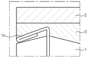
도 1을 참조하면, 종래의 배터리 모듈을 구성하는 파우치 타입 배터리 셀(1)이 나타나 있다. 상기 배터리 셀(1)은, 윙부(1a)가 폴딩된 형상을 가지며, 이처럼 윙부가 폴딩된 형태를 갖는 파우치 타입 배터리 셀의 경우, 폴딩된 윙부(1a)의 형상으로 인해 열 접촉 저항이 증가하게 된다.1, a pouch type battery cell 1 constituting a conventional battery module is shown. The battery cell 1 has a folded shape of the
즉, 상기 배터리 셀(1)의 엣지와 냉각 플레이트(2) 사이에는 TIM 층(thermal interface material layer)(3)이 개재될 수 있는데, 윙부(1a)의 형성에 따른 배터리 셀(1) 엣지부의 복잡한 형상으로 인해, TIM 층(3)과 배터리 셀(1) 사이의 열 접촉 저항이 증가하게 되는 것이다.That is, a thermal interface material layer (TIM)
이러한 열 접촉 저항의 증가는, 배터리 모듈의 냉각효율 저하로 이어지게 되며, 이러한 냉각효율의 저하는 배터리 모듈의 성능 및 수명 저하로 이어질 수 있다.The increase in thermal contact resistance leads to a decrease in cooling efficiency of the battery module, and a decrease in the cooling efficiency may lead to a decrease in performance and life of the battery module.
본 발명은, 상술한 문제점을 고려하여 창안된 것으로서, 배터리 모듈을 구성하는 각각의 배터리 셀들이 하나의 파우치 케이스를 통해 연결된 구조를 갖도록 하고, 이로써 셀 적층체의 제조 공정을 간소하게 하여 배터리 모듈 제조 공정의 효율을 향상시키는 것을 일 목적으로 한다.The present invention has been devised in consideration of the above-mentioned problems, so that each of the battery cells constituting the battery module has a structure connected through one pouch case, thereby simplifying the manufacturing process of the cell stack to manufacture the battery module It aims to improve the efficiency of a process.
또한, 본 발명은, 셀 적층체의 엣지 부분의 형상을 간단하게 하여 냉각을 위한 부재와 셀 적층체의 엣지 부분 간의 열 접촉 저항을 최소화 함으로써 배터리 모듈의 냉각 효율을 향상시키는 것을 다른 목적으로 한다.Another object of the present invention is to improve the cooling efficiency of the battery module by simplifying the shape of the edge portion of the cell stack to minimize thermal contact resistance between the member for cooling and the edge portion of the cell stack.
다만, 본 발명이 해결하고자 하는 기술적 과제는 상술한 과제에 제한되지 않으며, 언급되지 않은 또 다른 과제들은 아래에 기재된 발명의 설명으로부터 당업자에게 명확하게 이해될 수 있을 것이다.However, the technical problem to be solved by the present invention is not limited to the above-described problems, and other problems that are not mentioned will be clearly understood by those skilled in the art from the description of the invention described below.
상술한 과제를 해결하기 위한 본 발명의 일 실시예에 따른 배터리 모듈은, 복수의 배터리 셀을 포함하며, 서로 인접한 배터리 셀 사이가 파우치 케이스에 의해 상호 연결된 형태를 갖는 셀 적층체; 상기 셀 적층체의 일측에 구비되며, 상기 셀 적층체와 직접 또는 간접적으로 접촉하는 제1 냉각 플레이트; 및 상기 셀 적층체의 타측에 구비되며, 상기 셀 적층체와 직접 또는 간접적으로 접촉하는 제2 냉각 플레이트; 를 포함한다.A battery module according to an embodiment of the present invention for solving the above-described problem includes a plurality of battery cells, a cell stack having mutually adjacent battery cells connected to each other by a pouch case; A first cooling plate provided on one side of the cell stack and directly or indirectly contacting the cell stack; And a second cooling plate provided on the other side of the cell stack and directly or indirectly contacting the cell stack. It includes.
상기 배터리 모듈은, 상기 셀 적층체와 제1 냉각 플레이트 사이 및 상기 셀 적층체와 제2 냉각 플레이트 사이에 각각 개재되는 TIM 층을 더 포함할 수 있다.The battery module may further include a TIM layer interposed between the cell stack and the first cooling plate and between the cell stack and the second cooling plate, respectively.
상기 셀 적층체는, 파우치 케이스; 상기 파우치 케이스 내에 수용되며, 상기 파우치 케이스의 길이 방향을 따라 서로 소정의 간격을 두고 상호 이격되어 배치되는 복수의 전극 조립체; 및 상기 복수의 전극 조립체 각각에 구비되어 상기 파우치 케이스의 실링 영역을 통해 외부로 인출되는 전극 리드; 를 포함할 수 있다.The cell stack, pouch case; A plurality of electrode assemblies accommodated in the pouch case, and spaced apart from each other at predetermined intervals along the longitudinal direction of the pouch case; And an electrode lead provided on each of the plurality of electrode assemblies and drawn out through the sealing area of the pouch case. It may include.
상기 파우치 케이스는, 복수의 배터리 셀들이 서로 대면하도록, 서로 인접한 전극 조립체 사이에 형성되는 공간을 기준으로 하여 폴딩될 수 있다.The pouch case may be folded based on a space formed between adjacent electrode assemblies so that a plurality of battery cells face each other.
상기 배터리 셀은, 양 측부에 형성되는 윙부를 구비할 수 있다.The battery cell may include wing portions formed on both sides.
서로 인접한 배터리 셀 상호 간은 상기 윙부가 서로 연결될 수 있다.The wing portions may be connected to each other between adjacent battery cells.
상기 냉각 플레이트는 상기 윙부와 직접 또는 간접적으로 접촉할 수 있다.The cooling plate may contact the wing portion directly or indirectly.
상기 배터리 모듈은, 상기 서로 인접한 배터리 셀 사이에 개재되어 상기 제1 냉각 플레이트와 접촉하는 제3 냉각 플레이트; 및 상기 서로 인접한 배터리 셀 사이에 개재되어 상기 제2 냉각 플레이트와 접촉하는 제4 냉각 플레이트; 를 포함할 수 있다.The battery module may include a third cooling plate interposed between the adjacent battery cells and in contact with the first cooling plate; And a fourth cooling plate interposed between the battery cells adjacent to each other to contact the second cooling plate. It may include.
상기 제3 냉각 플레이트 및 제4 냉각 플레이트는, 상기 셀 적층체의 폭 방향을 따라 번갈아 배치될 수 있다.The third cooling plate and the fourth cooling plate may be alternately arranged along the width direction of the cell stack.
한편, 상술한 과제를 해결하기 위한 본 발명의 일 실시예에 따른 배터리 팩은, 상기 배터리 모듈을 복수개 포함하는 형태로 구현된다.On the other hand, the battery pack according to an embodiment of the present invention for solving the above-described problem is implemented in a form including a plurality of the battery module.
본 발명의 일 측면에 따르면, 배터리 모듈을 구성하는 각각의 배터리 셀들이 하나의 파우치 케이스를 통해 연결된 구조를 갖게 되어 셀 적층체의 형성 공정이 간소하게 되고, 이로써 배터리 모듈 제조 공정의 효율을 향상시킬 수 있다.According to an aspect of the present invention, since each battery cell constituting the battery module has a structure connected through one pouch case, the process of forming the cell stack is simplified, thereby improving the efficiency of the battery module manufacturing process. You can.
본 발명의 다른 측면에 따르면, 셀 적층체의 엣지 부분의 형상이 간단하게 되어 냉각을 위한 부재와 셀 적층체의 엣지 부분 간의 열 접촉 저항의 증가가 억제되고, 이로써 배터리 모듈의 냉각 효율이 향상될 수 있다.According to another aspect of the present invention, the shape of the edge portion of the cell stack is simplified, so that an increase in thermal contact resistance between the member for cooling and the edge portion of the cell stack is suppressed, thereby improving the cooling efficiency of the battery module. You can.
본 명세서에 첨부되는 다음의 도면들은 본 발명의 바람직한 실시예를 예시하는 것이며, 후술되는 발명의 상세한 설명과 함께 본 발명의 기술사상을 더욱 이해시키는 역할을 하는 것이므로, 본 발명은 그러한 도면에 기재된 사항에만 한정되어 해석되어서는 아니 된다.
도 1은, 종래의 배터리 모듈을 구성하는 셀 적층체의 일부를 나타내는 도면이다.
도 2는, 본 발명의 일 실시예에 따른 배터리 모듈을 나타내는 도면이다.
도 3은, 본 발명의 일 시시예에 따른 배터리 모듈의 일부를 나타내는 부분 확대도이다.
도 4는, 본 발명의 일 실시예에 따른 배터리 모듈에 적용되는 셀 적층체를 나타내는 도면이다.
도 5 및 도 6은, 본 발명의 일 실시예에 따른 배터리 모듈에 적용되는 셀 적층체의 제조 공정을 설명하기 위한 도면이다.The following drawings attached to this specification are intended to illustrate preferred embodiments of the present invention, and serve to further understand the technical idea of the present invention together with the detailed description of the invention described below, and thus the present invention is described in such drawings. It is not limited to interpretation.
1 is a view showing a part of a cell stack that constitutes a conventional battery module.
2 is a view showing a battery module according to an embodiment of the present invention.
3 is a partially enlarged view showing a part of a battery module according to an exemplary embodiment of the present invention.
4 is a view showing a cell stack applied to a battery module according to an embodiment of the present invention.
5 and 6 are views for explaining a manufacturing process of a cell stack applied to a battery module according to an embodiment of the present invention.
이하, 첨부된 도면을 참조하여 본 발명의 바람직한 실시예를 상세히 설명하기로 한다. 이에 앞서, 본 명세서 및 청구범위에 사용된 용어나 단어는 통상적이거나 사전적인 의미로 한정해서 해석되어서는 아니 되며, 발명자는 그 자신의 발명을 가장 최선의 방법으로 설명하기 위해 용어의 개념을 적절하게 정의할 수 있다는 원칙에 입각하여 본 발명의 기술적 사상에 부합하는 의미와 개념으로 해석되어야만 한다. 따라서, 본 명세서에 기재된 실시예와 도면에 도시된 구성은 본 발명의 가장 바람직한 일부 실시예에 불과할 뿐이고 본 발명의 기술적 사상을 모두 대변하는 것은 아니므로, 본 출원시점에 있어서 이들을 대체할 수 있는 다양한 균등물과 변형예들이 있을 수 있음을 이해하여야 한다.Hereinafter, preferred embodiments of the present invention will be described in detail with reference to the accompanying drawings. Prior to this, the terms or words used in the present specification and claims should not be construed as being limited to ordinary or lexical meanings, and the inventor appropriately explains the concept of terms to explain his or her invention in the best way. Based on the principle that it can be defined, it should be interpreted as meanings and concepts consistent with the technical spirit of the present invention. Therefore, the embodiments shown in the embodiments and the drawings shown in the specification are only some of the most preferred embodiments of the present invention, and do not represent all of the technical spirit of the present invention. It should be understood that there may be equivalents and variations.
도 2 및 도 3을 참조하여, 본 발명의 일 실시예에 따른 배터리 모듈의 구조를 설명하기로 한다.2 and 3, the structure of the battery module according to an embodiment of the present invention will be described.
도 2는 본 발명의 일 실시예에 따른 배터리 모듈을 나타내는 도면이고, 도 3은 본 발명의 일 시시예에 따른 배터리 모듈의 일부를 나타내는 부분 확대도이다.2 is a view showing a battery module according to an embodiment of the present invention, Figure 3 is a partial enlarged view showing a part of the battery module according to an embodiment of the present invention.
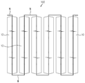
도 2 및 도 3을 참조하면, 본 발명의 일 실시예에 따른 배터리 모듈은 셀 적층체(100) 및 냉각 부재(200)를 포함한다. 2 and 3, a battery module according to an embodiment of the present invention includes a
상기 셀 적층체(100)는, 서로 연결되어 있는 복수의 배터리 셀(10)을 포함하며, 이러한 배터리 셀(10)들이 상호 대면하도록 적층된 형태를 갖는다. 상기 배터리 셀(10)들은, 파우치 타입의 배터리 셀로서 후술할 파우치 케이스(13)(도 5 참조)에 의해 상호 연결된 형태를 갖는다.The
즉, 복수의 배터리 셀(10) 각각의 양 측부에는 윙부(W)가 형성되는데, 서로 인접한 배터리 셀(10) 상호간은 각각의 윙부(W)가 서로 연결된 형태를 갖는다.That is, the wing portion W is formed on both sides of each of the plurality of
상기 냉각 부재(200)는, 셀 적층체(100)의 일측 및 타측에 각각 구비되는 제1 냉각 플레이트(210) 및 제2 냉각 플레이트(220)를 포함한다. 또한, 상기 냉각 부재(200)는, 인접한 배터리 셀(10) 사이에 개재되는 제3 냉각 플레이트(230) 및 제4 냉각 플레이트(240)를 더 포함할 수도 있다.The
상기 제1 냉각 플레이트(210)는, 셀 적층체(100)의 일측에 구비되며, 인접한 배터리 셀(10) 사이를 연결하는 윙부(W)와 직접 또는 간접적으로 접촉한다.The
상기 제2 냉각 플레이트(220)는, 셀 적층체(100)의 타측에 구비되며, 앞서 설명한 제1 냉각 플레이트(210)와 마찬가지로, 인접한 배터리 셀(10) 사이를 연결하는 윙부(W)와 직접 또는 간접적으로 접촉한다.The
상기 제3 냉각 플레이트(230)는, 서로 인접한 배터리 셀(10) 사이에 개재되며, 배터리 셀(10)의 폭 방향(도 2의 Y축과 나란한 방향)을 따라 연장되어 제1 냉각 플레이트(210)와 접촉한다. 상기 제1 냉각 플레이트(210)와 제3 냉각 플레이트(230)는, 서로 별개의 부품일 수도 있고 일체로 형성될 수도 있다.The
상기 제4 냉각 플레이트(240)는, 서로 인접한 배터리 셀(10) 사이에 개재되며, 배터리 셀(10)의 폭 방향(도 2의 Y축과 나란한 방향)을 따라 연장되어 제2 냉각 플레이트(220)와 접촉한다. 상기 제2 냉각 플레이트(220)와 제4 냉각 플레이트(240)는, 서로 별개의 부품일 수도 있고, 일체로 형성될 수도 있다.The
상기 제3 냉각 플레이트(230) 및 제4 냉각 플레이트(240)는, 셀 적층체(100)의 폭 방향(도 2의 X축과 나란한 방향)을 따라 번갈아 배치될 수 있다.The
한편, 상기 배터리 모듈은, 셀 적층체(100)와 제1 냉각 플레이트(210) 사이 및 셀 적층체(100)와 제2 냉각 플레이트(220) 사이에 각각 개재되는 TIM 층(thermal interface material layer)(300)을 더 포함할 수도 있다.Meanwhile, the battery module includes a thermal interface material layer (TIM) layer interposed between the
상기 TIM 층(300)은, 셀 적층체(100) 중 제1 냉각 플레이트(210)와 대면하는 영역 및 제2 냉각 플레이트(220)와 대면하는 영역이 평탄한 형상을 갖지 않아 셀 적층체(100)와 각각의 냉각 플레이트(210, 220) 간의 접촉 면적이 줄어들고, 이로써 냉각 효율이 떨어지는 것을 보완하기 위해 적용되는 것이다.In the TIM
상기 TIM 층(300)은, 제1, 제2 냉각 플레이트(210, 220)와 대면하는 셀 적층체(100)의 형상을 따라 형성되며, 이로써 냉각 플레이트(210, 220)와 셀 적층체(100) 간의 간접적인 접촉 면적을 극대화 함으로써 냉각 효율을 높여준다.The TIM
다음은, 도 4 내지 도 6을 참조하여, 본 발명의 일 실시예에 따른 배터리 모듈에 적용되는 셀 적층체(100)에 대해서 상세히 설명하기로 한다.Next, with reference to FIGS. 4 to 6, the
도 4는 본 발명의 일 실시예에 따른 배터리 모듈에 적용되는 셀 적층체를 나타내는 도면이고, 도 5 및 도 6은 본 발명의 일 실시예에 따른 배터리 모듈에 적용되는 셀 적층체의 제조 공정을 설명하기 위한 도면이다.4 is a view showing a cell stack applied to a battery module according to an embodiment of the present invention, and FIGS. 5 and 6 are processes for manufacturing a cell stack applied to a battery module according to an embodiment of the present invention It is a figure for illustration.
도 4 내지 도 6을 참조하면, 본 발명에 적용되는 셀 적층체(100)는 복수의 배터리 셀(10)들이 상호 대면하도록 적층된 형태를 가지며, 각각의 배터리 셀(10)들은 파우치 케이스(13)의 실링 영역 중 일부에 해당하는 윙부(W)에 의해 연결되어 있다.4 to 6, the
도 5 및 도 6에 나타나듯이, 복수의 상기 배터리 셀(10)은 개별적으로 제조되는 것이 아니라, 복수의 전극 조립체(11)들을 하나의 파우치 케이스(13) 내에 수용시킴으로써 한꺼번에 제조된다.5 and 6, a plurality of the
각각의 배터리 셀(10)은 전극 조립체(11), 전극 리드(12) 및 파우치 케이스(13)를 포함한다.Each
도면에 도시되지는 않았으나, 상기 전극 조립체(11)는, 양극, 음극 및 양극과 음극 사이에 개재되는 분리막을 포함하며, 이러한 양극, 음극 및 분리막이 1회 이상 적층된 형태 또는 양극, 음극 및 분리막이 적층되어 형성된 적층체가 권취된 형태를 가질 수 있다. 상기 양극은, 양극 집전체 및 양극 집전체의 적어도 일 면 상에 코팅된 양극 활물질 층을 포함한다. 또한, 상기 음극은, 음극 집전체 및 음극 집전체의 적어도 일 면 상에 코팅된 음극 활물질 층을 포함한다. Although not shown in the drawing, the
상기 전극 리드(12)는, 각각의 배터리 셀(10)마다 한 쌍씩 구비되는 것으로서, 전극 조립체(11)에 형성된 전극탭(미도시)에 연결되어 파우치 케이스(13)의 외부로 인출된다. 본 발명의 도면에서는 한 쌍의 상기 전극 리드(12)가 모두 전극 조립체의 일 측에 결합되어 동일한 방향으로 연장되는 경우만을 도시하고 있으나, 본 발명이 반드시 이에 한정되는 것은 아니다. 즉, 한 쌍의 전극 리드(12)는, 전극 조립체(11)의 일측 및 그 반대편인 타측에 각각 하나씩 구비되어 서로 반대방향으로 연장될 수도 있는 것이다.The
상기 파우치 케이스(13)는, 하부 케이스(13a) 및 상부 케이스(13b)를 포함하며, 각각의 케이스(13a, 13b)는 수지층/금속층/수지층의 순서로 적층된 파우치 필름으로 이루어진다.The
도 5에 나타난 바와 같이, 전극 리드(12)가 결합된 복수의 전극 조립체(11)들은, 먼저 하부 케이스(13a) 상에 소정의 간격을 두고 서로 이격되어 배치된다. 이 후, 도 6에 나타난 바와 같이, 상부 케이스(13b)가 전극 조립체(11)들을 커버하며 상부로부터 결합된다. 상기 하부 케이스(13a)와 상부 케이스(13b) 간의 결합은, 하부 케이스(13a)와 상부 케이스(13b)가 맞닿는 면이 열 융착 등의 방식에 의해 실링(sealing) 됨으로써 이루어진다.As shown in FIG. 5, the plurality of
상기 하부 케이스(13a)와 상부 케이스(13b) 중 적어도 어느 한 쪽에는 전극 조립체(11)와 대응되는 위치에 대응되는 형상으로 형성되어 전극 조립체(11)를 수용하는 수용부가 구비된다. 또한, 상기 수용부의 둘레에는 하부 케이스(13a)와 상부 케이스(13b)가 맞닿아 결합되는 실링 영역이 형성된다. At least one of the
실링 영역을 형성함에 있어서, 파우치 케이스(13)의 폭 방향(도 5 및 도 6을 기준으로 볼 때, 위아래 방향을 위미함) 일측과 타측 중 어느 한 곳을 제외한 나머지 영역이 우선적으로 실링된다. 이는 전해질의 주입을 위한 것으로서, 실링이 이루어지지 않은 영역(A)을 통해 전해질을 주입한 후, 해당 영역을 마저 실링 함으로써 파우치 케이스(13)가 밀봉된다.In forming the sealing area, the rest of the area except for one of the one side and the other side of the
이와 같이, 본 발명에 따른 셀 적층체(100)는, 하나의 파우치 케이스(13)를 이용하여 제조되므로, 복수의 배터리 셀(10)들이 파우치 케이스(13)를 통해 서로 연결된 형태를 갖게 된다.As described above, since the
본 발명에서는, 각각의 배터리 셀(10)에 있어서, 폭 방향(도 5 및 도 6을 기준으로 볼 때, 좌우 방향을 의미함) 양 측부에 형성된 실링 영역을 윙부(W)라 칭하기로 한다. 이 경우, 서로 인접한 배터리 셀(10)들은 윙부(W)에 의해서 연결된다.In the present invention, in each
또한, 상기 윙부(W)는 복수의 배터리 셀(10)들이 서로 대면하면서 적층된 형태를 갖도록 하기 위한 폴딩(folding)의 기준이 된다. 즉, 상기 셀 적층체(100)는, 윙부(W)를 기준으로 하여 인접한 배터리 셀(10)이 서로 대면하도록 폴딩된 형태를 갖는다.In addition, the wing portion W is a reference for folding so that a plurality of
상술한 바와 같이, 본 발명의 일 실시예에 따른 배터리 모듈은, 셀 적층체(100)를 구성하는 각각의 배터리 셀(10)들이 하나의 파우치 케이스(13)에 의해 모두 연결된 형태를 가짐으로써 케이싱(casing) 공정 및 실링 공정 등의 작업 효율을 높일 수 있다.As described above, in the battery module according to an embodiment of the present invention, each
또한, 본 발명의 일 실시예에 따른 배터리 모듈은, 서로 인접한 배터리 셀(10)이 윙부(W)에 의해 연결되어 있어서, 냉각 플레이트(210, 220)와 대면하는 영역이 평탄한 형상을 가질 수 있다. 이로써 냉각 플레이트(210, 220) 및/또는 TIM 층(300)과의 접촉면에서의 열 접촉 저항이 최소화 될 수 있으며, 이에 따라 배터리 모듈의 냉각 효율을 높일 수 있다.In addition, in the battery module according to an embodiment of the present invention, the
한편, 본 발명의 일 실시예에 따른 배터리 팩은, 상술한 바와 같은 본 발명의 일 실시예에 따른 배터리 모듈이 복수개 연결된 형태로 구현된다.On the other hand, the battery pack according to an embodiment of the present invention is implemented in a form in which a plurality of battery modules according to an embodiment of the present invention are connected as described above.
이상에서 본 발명은 비록 한정된 실시예와 도면에 의해 설명되었으나, 본 발명은 이것에 의해 한정되지 않으며 본 발명이 속하는 기술분야에서 통상의 지식을 가진 자에 의해 본 발명의 기술사상과 아래에 기재될 특허청구범위의 균등범위 내에서 다양한 수정 및 변형이 가능함은 물론이다.Although the present invention has been described above by way of limited examples and drawings, the present invention is not limited by this and will be described below and the technical idea of the present invention by those skilled in the art to which the present invention pertains. Of course, various modifications and variations are possible within the equal scope of the claims.
100: 셀 적층체
10: 배터리 셀
11: 전극 조립체
12: 전극 리드
13: 파우치 케이스
13a: 하부 케이스
13b: 상부 케이스
W: 윙부
200: 냉각 부재
210: 제1 냉각 플레이트
220: 제2 냉각 플레이트
230: 제3 냉각 플레이트
240: 제4 냉각 플레이트100: cell laminate
10: battery cell
11: electrode assembly
12: electrode lead
13: pouch case
13a: lower case
13b: upper case
W: Wing
200: cooling member
210: first cooling plate
220: second cooling plate
230: third cooling plate
240: fourth cooling plate
Claims (10)
상기 셀 적층체의 일측에 구비되며, 상기 셀 적층체와 직접 또는 간접적으로 접촉하는 제1 냉각 플레이트; 및
상기 셀 적층체의 타측에 구비되며, 상기 셀 적층체와 직접 또는 간접적으로 접촉하는 제2 냉각 플레이트;
를 포함하는 배터리 모듈.A cell stack comprising a plurality of battery cells and having mutually adjacent battery cells interconnected by a pouch case;
A first cooling plate provided on one side of the cell stack and directly or indirectly contacting the cell stack; And
A second cooling plate provided on the other side of the cell stack and directly or indirectly contacting the cell stack;
Battery module comprising a.
상기 배터리 모듈은,
상기 셀 적층체와 제1 냉각 플레이트 사이 및 상기 셀 적층체와 제2 냉각 플레이트 사이에 각각 개재되는 TIM 층을 더 포함하는 것을 특징으로 하는 배터리 모듈.According to claim 1,
The battery module,
And a TIM layer interposed between the cell stack and the first cooling plate and between the cell stack and the second cooling plate, respectively.
상기 셀 적층체는,
파우치 케이스;
상기 파우치 케이스 내에 수용되며, 상기 파우치 케이스의 길이 방향을 따라 서로 소정의 간격을 두고 상호 이격되어 배치되는 복수의 전극 조립체; 및
상기 복수의 전극 조립체 각각에 구비되어 상기 파우치 케이스의 실링 영역을 통해 외부로 인출되는 전극 리드;
를 포함하는 것을 특징으로 하는 배터리 모듈.According to claim 1,
The cell laminate,
Pouch case;
A plurality of electrode assemblies accommodated in the pouch case, and spaced apart from each other at predetermined intervals along the longitudinal direction of the pouch case; And
An electrode lead provided on each of the plurality of electrode assemblies and drawn out through the sealing area of the pouch case;
Battery module comprising a.
상기 파우치 케이스는,
복수의 배터리 셀들이 서로 대면하도록, 서로 인접한 전극 조립체 사이에 형성되는 공간을 기준으로 하여 폴딩되는 것을 특징으로 하는 배터리 모듈.The method of claim 3,
The pouch case,
A battery module, characterized in that a plurality of battery cells are folded on the basis of a space formed between adjacent electrode assemblies so as to face each other.
상기 배터리 셀은,
양 측부에 형성되는 윙부를 구비하는 것을 특징으로 하는 배터리 모듈.According to claim 1,
The battery cell,
A battery module comprising wing portions formed on both sides.
서로 인접한 배터리 셀 상호 간은 상기 윙부가 서로 연결된 것을 특징으로 하는 배터리 모듈.The method of claim 5,
A battery module characterized in that the wing portions are connected to each other between adjacent battery cells.
상기 냉각 플레이트는 상기 윙부와 직접 또는 간접적으로 접촉하는 것을 특징으로 하는 배터리 모듈.The method of claim 6,
The cooling plate is a battery module, characterized in that in direct or indirect contact with the wing.
상기 배터리 모듈은,
상기 서로 인접한 배터리 셀 사이에 개재되어 상기 제1 냉각 플레이트와 접촉하는 제3 냉각 플레이트; 및
상기 서로 인접한 배터리 셀 사이에 개재되어 상기 제2 냉각 플레이트와 접촉하는 제4 냉각 플레이트;
를 포함하는 것을 특징으로 하는 배터리 모듈.According to claim 1,
The battery module,
A third cooling plate interposed between the adjacent battery cells and in contact with the first cooling plate; And
A fourth cooling plate interposed between the battery cells adjacent to each other to contact the second cooling plate;
A battery module comprising a.
상기 제3 냉각 플레이트 및 제4 냉각 플레이트는,
상기 셀 적층체의 폭 방향을 따라 번갈아 배치되는 것을 특징으로 하는 배터리 모듈.The method of claim 8,
The third cooling plate and the fourth cooling plate,
The battery module, characterized in that arranged alternately along the width direction of the cell stack.
Priority Applications (1)
| Application Number | Priority Date | Filing Date | Title |
|---|---|---|---|
| KR1020180106084A KR102614749B1 (en) | 2018-09-05 | 2018-09-05 | A battery module manufactured using a single pouch case and a battery pack including the same |
Applications Claiming Priority (1)
| Application Number | Priority Date | Filing Date | Title |
|---|---|---|---|
| KR1020180106084A KR102614749B1 (en) | 2018-09-05 | 2018-09-05 | A battery module manufactured using a single pouch case and a battery pack including the same |
Publications (2)
| Publication Number | Publication Date |
|---|---|
| KR20200027809A true KR20200027809A (en) | 2020-03-13 |
| KR102614749B1 KR102614749B1 (en) | 2023-12-14 |
Family
ID=69938352
Family Applications (1)
| Application Number | Title | Priority Date | Filing Date |
|---|---|---|---|
| KR1020180106084A KR102614749B1 (en) | 2018-09-05 | 2018-09-05 | A battery module manufactured using a single pouch case and a battery pack including the same |
Country Status (1)
| Country | Link |
|---|---|
| KR (1) | KR102614749B1 (en) |
Citations (3)
| Publication number | Priority date | Publication date | Assignee | Title |
|---|---|---|---|---|
| KR20170022741A (en) * | 2015-08-21 | 2017-03-02 | 주식회사 엘지화학 | Battery module |
| KR20170135473A (en) * | 2016-05-31 | 2017-12-08 | 주식회사 엘지화학 | Battery module, battery pack comprising the battery module and vehicle comprising the battery pack |
| KR20180023637A (en) * | 2016-08-26 | 2018-03-07 | 주식회사 엘지화학 | Battery module |
-
2018
- 2018-09-05 KR KR1020180106084A patent/KR102614749B1/en active IP Right Grant
Patent Citations (3)
| Publication number | Priority date | Publication date | Assignee | Title |
|---|---|---|---|---|
| KR20170022741A (en) * | 2015-08-21 | 2017-03-02 | 주식회사 엘지화학 | Battery module |
| KR20170135473A (en) * | 2016-05-31 | 2017-12-08 | 주식회사 엘지화학 | Battery module, battery pack comprising the battery module and vehicle comprising the battery pack |
| KR20180023637A (en) * | 2016-08-26 | 2018-03-07 | 주식회사 엘지화학 | Battery module |
Also Published As
| Publication number | Publication date |
|---|---|
| KR102614749B1 (en) | 2023-12-14 |
Similar Documents
| Publication | Publication Date | Title |
|---|---|---|
| KR102058194B1 (en) | battery module | |
| KR101451051B1 (en) | Secondary battery | |
| JP2019530176A (en) | Method for manufacturing electrode unit for battery cell and electrode unit | |
| TW201304248A (en) | Assembled cell | |
| KR20190114645A (en) | Pouch case, and secondary battery and secondary battery pack using the same | |
| KR102654935B1 (en) | Pouch type secondary battery and method of fabricating same | |
| KR101147241B1 (en) | Electrode assembly, rechargeable battery, and fabricating methode of electrode used thereof | |
| KR20210066528A (en) | Battery module and battery pack including the same | |
| KR102505729B1 (en) | Secondary battery | |
| EP3255722B1 (en) | Battery module having improved cooling structure | |
| US20220085461A1 (en) | Secondary battery | |
| JP2015056257A (en) | Secondary battery | |
| KR20200027809A (en) | A battery module manufactured using a single pouch case and a battery pack including the same | |
| JP2000200593A (en) | Battery pack | |
| KR102576583B1 (en) | Bettery cell | |
| JP7304369B2 (en) | Non-aqueous electrolyte secondary battery | |
| US20230369653A1 (en) | Rechargeable battery, electrode assembly and method for manufacturing the same | |
| US20220384882A1 (en) | Outer package and battery | |
| JP5382079B2 (en) | Secondary battery | |
| KR102142565B1 (en) | Stepped unit battery cell and method of manufacturing the same | |
| KR20240009778A (en) | Pouch type rechargeable-battery | |
| TWM623167U (en) | Battery | |
| KR101811836B1 (en) | A Sealing Device For Battery Case having an unsealing portion employed with possibly adjusting heights | |
| KR20230129848A (en) | Pouch-type Battery Cell | |
| KR20230111915A (en) | Battery module and battery pack including the same |
Legal Events
| Date | Code | Title | Description |
|---|---|---|---|
| A201 | Request for examination | ||
| N231 | Notification of change of applicant | ||
| E902 | Notification of reason for refusal | ||
| E701 | Decision to grant or registration of patent right | ||
| GRNT | Written decision to grant |