KR20200026909A - Lighting system comprising a light transmissive structure and a light transmissive structure for redistribution of light - Google Patents
Lighting system comprising a light transmissive structure and a light transmissive structure for redistribution of light Download PDFInfo
- Publication number
- KR20200026909A KR20200026909A KR1020207002382A KR20207002382A KR20200026909A KR 20200026909 A KR20200026909 A KR 20200026909A KR 1020207002382 A KR1020207002382 A KR 1020207002382A KR 20207002382 A KR20207002382 A KR 20207002382A KR 20200026909 A KR20200026909 A KR 20200026909A
- Authority
- KR
- South Korea
- Prior art keywords
- light transmissive
- light
- degrees
- transmissive structure
- angle
- Prior art date
Links
- 239000000758 substrate Substances 0.000 claims abstract description 21
- 238000009826 distribution Methods 0.000 claims description 78
- 238000005286 illumination Methods 0.000 claims description 12
- 238000005452 bending Methods 0.000 description 23
- 238000000034 method Methods 0.000 description 9
- 230000003287 optical effect Effects 0.000 description 5
- 239000000463 material Substances 0.000 description 3
- 230000007423 decrease Effects 0.000 description 2
- 238000004519 manufacturing process Methods 0.000 description 2
- 238000012986 modification Methods 0.000 description 2
- 230000004048 modification Effects 0.000 description 2
- 229920000642 polymer Polymers 0.000 description 2
- 230000005855 radiation Effects 0.000 description 2
- 239000011343 solid material Substances 0.000 description 2
- 238000010146 3D printing Methods 0.000 description 1
- 239000000654 additive Substances 0.000 description 1
- 230000000996 additive effect Effects 0.000 description 1
- 230000006835 compression Effects 0.000 description 1
- 238000007906 compression Methods 0.000 description 1
- 230000003247 decreasing effect Effects 0.000 description 1
- 229910003460 diamond Inorganic materials 0.000 description 1
- 239000010432 diamond Substances 0.000 description 1
- 238000004049 embossing Methods 0.000 description 1
- 238000001125 extrusion Methods 0.000 description 1
- 238000001093 holography Methods 0.000 description 1
- 238000003384 imaging method Methods 0.000 description 1
- 238000001746 injection moulding Methods 0.000 description 1
- 238000000608 laser ablation Methods 0.000 description 1
- 238000003754 machining Methods 0.000 description 1
- 238000005459 micromachining Methods 0.000 description 1
- 238000000206 photolithography Methods 0.000 description 1
- 229920002120 photoresistant polymer Polymers 0.000 description 1
- 230000010076 replication Effects 0.000 description 1
- 239000004065 semiconductor Substances 0.000 description 1
- 229920001169 thermoplastic Polymers 0.000 description 1
- 239000004416 thermosoftening plastic Substances 0.000 description 1
- 238000007514 turning Methods 0.000 description 1
Images


Classifications
-
- F—MECHANICAL ENGINEERING; LIGHTING; HEATING; WEAPONS; BLASTING
- F21—LIGHTING
- F21V—FUNCTIONAL FEATURES OR DETAILS OF LIGHTING DEVICES OR SYSTEMS THEREOF; STRUCTURAL COMBINATIONS OF LIGHTING DEVICES WITH OTHER ARTICLES, NOT OTHERWISE PROVIDED FOR
- F21V5/00—Refractors for light sources
- F21V5/002—Refractors for light sources using microoptical elements for redirecting or diffusing light
- F21V5/005—Refractors for light sources using microoptical elements for redirecting or diffusing light using microprisms
-
- F—MECHANICAL ENGINEERING; LIGHTING; HEATING; WEAPONS; BLASTING
- F21—LIGHTING
- F21V—FUNCTIONAL FEATURES OR DETAILS OF LIGHTING DEVICES OR SYSTEMS THEREOF; STRUCTURAL COMBINATIONS OF LIGHTING DEVICES WITH OTHER ARTICLES, NOT OTHERWISE PROVIDED FOR
- F21V5/00—Refractors for light sources
- F21V5/08—Refractors for light sources producing an asymmetric light distribution
-
- G—PHYSICS
- G02—OPTICS
- G02B—OPTICAL ELEMENTS, SYSTEMS OR APPARATUS
- G02B19/00—Condensers, e.g. light collectors or similar non-imaging optics
- G02B19/0004—Condensers, e.g. light collectors or similar non-imaging optics characterised by the optical means employed
- G02B19/0009—Condensers, e.g. light collectors or similar non-imaging optics characterised by the optical means employed having refractive surfaces only
-
- G—PHYSICS
- G02—OPTICS
- G02B—OPTICAL ELEMENTS, SYSTEMS OR APPARATUS
- G02B19/00—Condensers, e.g. light collectors or similar non-imaging optics
- G02B19/0033—Condensers, e.g. light collectors or similar non-imaging optics characterised by the use
- G02B19/0047—Condensers, e.g. light collectors or similar non-imaging optics characterised by the use for use with a light source
-
- G—PHYSICS
- G02—OPTICS
- G02B—OPTICAL ELEMENTS, SYSTEMS OR APPARATUS
- G02B5/00—Optical elements other than lenses
- G02B5/02—Diffusing elements; Afocal elements
- G02B5/0205—Diffusing elements; Afocal elements characterised by the diffusing properties
- G02B5/021—Diffusing elements; Afocal elements characterised by the diffusing properties the diffusion taking place at the element's surface, e.g. by means of surface roughening or microprismatic structures
- G02B5/0215—Diffusing elements; Afocal elements characterised by the diffusing properties the diffusion taking place at the element's surface, e.g. by means of surface roughening or microprismatic structures the surface having a regular structure
-
- G—PHYSICS
- G02—OPTICS
- G02B—OPTICAL ELEMENTS, SYSTEMS OR APPARATUS
- G02B5/00—Optical elements other than lenses
- G02B5/02—Diffusing elements; Afocal elements
- G02B5/0205—Diffusing elements; Afocal elements characterised by the diffusing properties
- G02B5/021—Diffusing elements; Afocal elements characterised by the diffusing properties the diffusion taking place at the element's surface, e.g. by means of surface roughening or microprismatic structures
- G02B5/0231—Diffusing elements; Afocal elements characterised by the diffusing properties the diffusion taking place at the element's surface, e.g. by means of surface roughening or microprismatic structures the surface having microprismatic or micropyramidal shape
-
- G—PHYSICS
- G02—OPTICS
- G02B—OPTICAL ELEMENTS, SYSTEMS OR APPARATUS
- G02B5/00—Optical elements other than lenses
- G02B5/02—Diffusing elements; Afocal elements
- G02B5/0205—Diffusing elements; Afocal elements characterised by the diffusing properties
- G02B5/0257—Diffusing elements; Afocal elements characterised by the diffusing properties creating an anisotropic diffusion characteristic, i.e. distributing output differently in two perpendicular axes
-
- G—PHYSICS
- G02—OPTICS
- G02B—OPTICAL ELEMENTS, SYSTEMS OR APPARATUS
- G02B5/00—Optical elements other than lenses
- G02B5/02—Diffusing elements; Afocal elements
- G02B5/0273—Diffusing elements; Afocal elements characterized by the use
- G02B5/0278—Diffusing elements; Afocal elements characterized by the use used in transmission
-
- G—PHYSICS
- G02—OPTICS
- G02B—OPTICAL ELEMENTS, SYSTEMS OR APPARATUS
- G02B5/00—Optical elements other than lenses
- G02B5/02—Diffusing elements; Afocal elements
- G02B5/0273—Diffusing elements; Afocal elements characterized by the use
- G02B5/0294—Diffusing elements; Afocal elements characterized by the use adapted to provide an additional optical effect, e.g. anti-reflection or filter
-
- G—PHYSICS
- G02—OPTICS
- G02B—OPTICAL ELEMENTS, SYSTEMS OR APPARATUS
- G02B5/00—Optical elements other than lenses
- G02B5/04—Prisms
- G02B5/045—Prism arrays
Abstract
광 투과성 구조체는 대향하는 제1 및 제2 면을 갖는 광 투과성 기판, 및 제1 면 상에 마이크로프리즘 요소의 어레이를 포함한다. 각각의 마이크로프리즘 요소는 제2 면에 대해 제1 경사 각도로 배치된 제1 경사 표면, 및 제2 면에 대해 제2 경사 각도로 배치된 제2 경사 표면을 포함한다. 제1 경사 각도는 제2 경사 각도보다 작고, 제1 경사 표면과 제2 경사 표면 사이의 피크 각도는 약 70도 내지 약 100도의 범위에 있다. 제2 경사 표면은 이에 대해 수직인 각도에서 보았을 때 볼록한 곡률을 갖는다. 광 투과성 구조체는 제1 면과 대면하는 광원으로부터 방출된 광을 제1 방향으로 수신하고 제2 면으로부터 나오는 광을 제1 방향과 상이한 제2 방향으로 재분배하도록 구성된다.The light transmissive structure includes a light transmissive substrate having opposing first and second faces, and an array of microprism elements on the first face. Each microprism element includes a first inclined surface disposed at a first inclined angle with respect to the second face, and a second inclined surface disposed at a second inclined angle with respect to the second face. The first tilt angle is smaller than the second tilt angle, and the peak angle between the first tilt surface and the second tilt surface is in the range of about 70 degrees to about 100 degrees. The second inclined surface has a convex curvature when viewed at an angle perpendicular to it. The light transmissive structure is configured to receive light emitted from a light source facing the first face in a first direction and redistribute light exiting from the second face in a second direction different from the first direction.

Description
관련 출원에 대한 상호 참조Cross Reference to Related Application
본 출원은 2017년 6월 30일자로 출원되었고 발명의 명칭이 "LIGHT TRANSMISSIVE STRUCTURES FOR REDISTRIBUTION OF LIGHT AND LIGHTING SYSTEMS INCLUDING SAME"인 미국 가특허 출원 제62/527,573호에 대한 우선권을 주장하고, 이 출원의 전체 내용은 본 명세서에 참조로 포함된다.This application is filed on June 30, 2017 and claims priority to U.S. Provisional Patent Application No. 62 / 527,573 entitled "LIGHT TRANSMISSIVE STRUCTURES FOR REDISTRIBUTION OF LIGHT AND LIGHTING SYSTEMS INCLUDING SAME." The entire contents are incorporated herein by reference.
기술분야Technical Field
본 발명은 광원으로부터 방출된 광을 재분배하는 데에 사용될 수 있는 광 투과성 구조체 및 그러한 광 투과성 구조체를 포함하는 조명 시스템에 관한 것이다.The present invention relates to a light transmissive structure that can be used to redistribute light emitted from a light source and an illumination system comprising such a light transmissive structure.
고효율 LED 조명이 더욱 더 채택되고 있다. 통상적인 LED 광원은 약 120도의 반치폭(Full Width Half Max)("FWHM")을 갖는 램버시안 분포(Lambertian distribution)로 광을 방출한다. 하우징, 반사기 및 렌즈와 같은 조명 기구(또는 조명 시스템)의 요소와 결합된 LED는 FWHM이 1°만큼 낮은 것을 비롯하여 많은 광 분포를 생성할 수 있다. 통상적으로, 일반 조명용으로 판매되는 많은 비용 효율적인 LED는 120도 램버시안 변종이다. 많은 조명 기구(LED 및 전통적인 기구)는 일부 다운라이트, 작업등 및 트로퍼(troffer)에서 확인되는 것과 같이 평탄한 외부 표면을 갖는다. 이들 기구 중 다수에서, 미세 구조, 홀로그래픽 또는 체적 확산기와 같은 단순한 평면 확산기가 LED를 확산시켜 뷰어로부터 그 외관을 숨기고 조명 기구의 표면 외관을 매끄럽게 하는 데에 사용된다.High efficiency LED lighting is increasingly being adopted. Typical LED light sources emit light in a Lambertian distribution with a Full Width Half Max ("FWHM") of about 120 degrees. LEDs combined with elements of luminaires (or lighting systems) such as housings, reflectors, and lenses can produce many light distributions, including as low as 1 ° FWHM. Typically, many cost-effective LEDs sold for general lighting are 120 degree Lambertian variants. Many lighting fixtures (LEDs and traditional fixtures) have a flat outer surface as seen in some downlights, work lights and troffers. In many of these appliances, simple planar diffusers, such as microstructures, holographic or volume diffusers, are used to diffuse the LEDs to hide their appearance from the viewer and to smooth the surface appearance of the luminaire.
평면 확산기가 조명 기구에 사용될 때, 조명 기구 내부에 사용되는 광원, 렌즈, 하우징, 반사기, 배플 등과 같은 조명 기구의 요소의 조합은 본 명세서에서 소스 분포로 지칭되는 확산기의 수신면에 충돌하는 광 분포를 초래하게 된다. 사용된 요소에 따라, 소스 분포는 1°, 10°, 20°, 40°, 80°, 100°, 120°또는 140°를 포함하는 광범위한 FWHM 값을 가질 수 있다. 일부 경우에, 다른 요소로부터 많은 간섭을 받지 않고 확산기에 충돌하는 120°LED의 넓은 어레이가 120°근방의 소스 분포를 나타낼 것이다. 많은 경우에, 캔 스타일 다운라이트 또는 선형 월 워시 조명 기구(linear wall-wash luminaire)와 같은 조명 기구는 일반적으로 빔 각도의 확산을 제한하여 60°, 85° 또는 100°와 같은 중간 폭 소스 분포를 생성하는 반사성인 내부 측벽을 포함할 수 있다.When a planar diffuser is used in a luminaire, the combination of elements of the luminaire, such as a light source, lens, housing, reflector, baffle, etc., used inside the luminaire may impinge on the light distribution impinging on the receiving face of the diffuser, referred to herein as the source distribution. Will result. Depending on the factor used, the source distribution can have a wide range of FWHM values, including 1 °, 10 °, 20 °, 40 °, 80 °, 100 °, 120 ° or 140 °. In some cases, a wide array of 120 ° LEDs that impinge on the diffuser without much interference from other elements will exhibit a source distribution near 120 °. In many cases, luminaires, such as can-style downlights or linear wall-wash luminaires, typically limit the spread of the beam angle to produce a medium width source distribution such as 60 °, 85 ° or 100 °. It may include reflective inner sidewalls to create.
많은 조명 시스템에서, 조명될 목표 영역은 광원의 방출 영역보다 훨씬 더 크다. 광 분포는 통상적으로 조명 기술 협회(Illuminating Engineering Society)("IES")의 LM-79 표준에 설명된 것과 유사한 각도 측정 장치를 사용하는 방법으로 측정된다. 여기에 설명된 바와 같이, 광도(luminous intensity)는 광학 검출기에 의해 광원의 주축으로부터의 각도의 함수로서 측정된다. 광학 검출기 및/또는 광원은 서로에 대해 이동되어 광학 검출기가 원하는 각도에서 방출된 광을 측정한다.In many lighting systems, the target area to be illuminated is much larger than the emission area of the light source. Light distribution is typically measured by using an angle measuring device similar to that described in the LM-79 standard of the Illuminating Engineering Society ("IES"). As described herein, luminous intensity is measured by an optical detector as a function of angle from the major axis of the light source. The optical detector and / or light source are moved relative to each other so that the optical detector measures the light emitted at the desired angle.
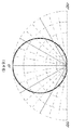
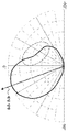
도 1은 하향 대면 광원(downward-facing light source)으로부터 방출된 광의 광도 분포를 나타내는 극 좌표이고, 이 예에서 하향 대면 광원은 FWHM이 120도인 램버시안 광 분포를 갖는 광원이다. 광도는 좌표에서 0°로 고려되는 천저점(즉, 하향 대면 방향)으로부터 각도의 코사인에 비례한다. 바닥과 같은 평탄한 표면이 램버시안 광 분포에 의해 조명될 때, 바닥의 조도는 천저점(기구 바로 아래)에서 가장 높고 천저점으로부터 멀어지는 바닥 상의 지점에 대해 단조롭게 감소한다. 조명 산업에서, 용어 "램버시안"은 또한 유사한 품질이지만 상이한 폭을 갖는 광 분포를 가리키는 데에 자주 사용된다. 즉, 천저점에서 피크를 갖고 더 높은 각도에서 단조롭게 감소하는 분포가 흔히 램버시안으로 명명된다. 일 예에서, FWHM이 80도인 가우시안 분포가 흔히 조명 산업에서 "램버시안"으로 명명될 것이다.FIG. 1 is a polar coordinate representing the luminance distribution of light emitted from a downward-facing light source, and in this example the downward facing light source is a light source having a Lambertian light distribution with an FWHM of 120 degrees. Luminance is proportional to the cosine of the angle from the bottom point (ie, downward facing direction), which is considered 0 ° in coordinates. When a flat surface, such as a floor, is illuminated by a Lambertian light distribution, the roughness of the floor decreases monotonically for the point on the floor that is highest at the bottom (just below the instrument) and away from the bottom. In the lighting industry, the term “lambertian” is also often used to refer to light distributions of similar quality but with different widths. That is, a distribution with peaks at the bottom and monotonically decreasing at higher angles is often named Lambertian. In one example, a Gaussian distribution with an FWHM of 80 degrees will often be named "Lambertian" in the lighting industry.
조명 및 다른 분야에서, 광원으로부터 방출되는 광을 벤딩시키는 것이 바람직할 수 있다. 조명 용례에서, 예를 들어 80도 각도를 갖는 다운라이트로부터의 광 분포 및 다운라이트의 주축 바로 아래에 센터링된 출력을 취하고, 분포가 비대칭 출력 분포, 즉 다운라이트의 일측에 센터링된 출력을 갖도록 분포를 시프트시키는 것이 바람직할 수 있다. 이는 벽, 표지판 또는 수술 환자와 같은 목표 영역에서 조명을 증가시키거나, 다른 용도 중에서도 비수직 각도로부터의 디스플레이 또는 표지판의 가시성을 개선시키는 것이 바람직할 수 있다. 또한, 소스 분포 및 출력이 직선 하향 방향(즉, 광원 바로 아래에 위치된 표면에 수직)에 대해 일정 각도로 센터링되도록 광원을 일정 각도로 돌린 다음, 광 분포를 추가로 벤딩하고 및/또는 비대칭 분포를 제공하는 것이 바람직할 수 있다.In lighting and other applications, it may be desirable to bend light emitted from a light source. In lighting applications, for example, it takes a light distribution from a downlight with an angle of 80 degrees and an output centered just below the main axis of the downlight and the distribution has an asymmetrical output distribution, ie an output centered on one side of the downlight. It may be desirable to shift. This may be desirable to increase illumination in a target area, such as a wall, sign or surgical patient, or to improve the visibility of a display or sign from a non-vertical angle, among other uses. Also, turn the light source at an angle so that the source distribution and output are centered at an angle with respect to the straight downward direction (ie, perpendicular to the surface located directly below the light source), then further bend the light distribution and / or asymmetrical distribution. It may be desirable to provide.
이 목적을 위해 캘리포니아주 토렌스 소재의 Luminit LLC로부터의 방향 선회 필름(Direction Turning Film) 및 미네소타주 세인트 폴 소재의 3M Optical Systems으로부터의 이미지 지향 필름 II(Image Directing Film II)에 의해 제공되는 것과 같은 평탄한 표면에 배열된 평행 선형 프리즘이 사용될 수 있다. 그러나, 이들 공지된 선형 프리즘 제품은 잘못된 방향으로 방출되는 못마땅한 품질의 광을 가질 수 있다. 예를 들어, 120도 램버시안 광원을 갖는 조명 기구에서는, 벽을 조명하기 위해 벽을 향해 광을 벤딩시키는 것이 바람직할 수 있다. 동시에, 원치않는 방향(즉, 벽에서 멀어지는)으로 남아있는 임의의 광이 0도(조명 기구 바로 아래에서 보는)에서 시작하는 기구를 보고 벤딩 방향(벽과 조명 기구로부터 멀리 있는)으로부터 멀어지게 90도 시야각에 접근하는 광으로부터 멀어지게 이동할 때 매끄럽고 단조롭게 페이드되게 하는 것이 바람직할 수 있다.For this purpose, flat such as those provided by Direction Turning Film from Luminit LLC, Torrance, Calif. And Image Directing Film II from 3M Optical Systems, St. Paul, Minn. Parallel linear prisms arranged on the surface can be used. However, these known linear prismatic products can have light of poor quality that is emitted in the wrong direction. For example, in a luminaire having a 120 degree Lambertian light source, it may be desirable to bend light towards the wall to illuminate the wall. At the same time, any light remaining in an undesired direction (i.e. away from the wall) may be viewed 90 degrees away from the bending direction (far from the wall and lighting fixture) by looking at the instrument starting at 0 degrees (just below the lighting fixture). It may also be desirable to fade smoothly and monotonously when moving away from the light approaching the viewing angle.
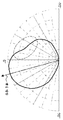
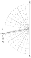
도 2 및 도 3은 각각 방향 전환 필름 및 이미지 지향 필름 II를 통과하는 120°소스 분포를 갖는 램버시안 광원을 사용하여 측정된 벤딩 평면에서의 광 분포를 도시하는 극 좌표이다. 광 분포 곡선의 좌측에 있는 광 분포 곡선의 부분(점선 타원형으로 나타냄)은 벤딩된 광이 어떻게 벤딩 방향으로부터 0도에서 90도까지 단조롭고 매끄럽게 페이드되지 않는지를 예시한다. 도 4 및 도 5는 각각 방향 전환 필름 및 이미지 지향 필름 II를 통과하는 80°소스 분포를 갖는 램버시안 광원을 사용하여 측정된 벤딩 평면에서의 광 분포를 도시하는 극 좌표이다. 예시된 바와 같이, 점선 타원형 내의 광 분포 곡선의 좌측에 있는 "돌출부"에 의해 입증되는 바와 같이, 광은 벤딩 방향으로부터 0도에서 90도까지 단조롭고 매끄럽게 페이드되지 않는다.2 and 3 are polar coordinates showing the light distribution in the bending plane measured using a Lambertian light source with a 120 ° source distribution through the redirection film and the image directing film II, respectively. The portion of the light distribution curve to the left of the light distribution curve (indicated by the dotted ovals) illustrates how the bent light does not fade smoothly and smoothly from 0 degrees to 90 degrees from the bending direction. 4 and 5 are polar coordinates showing the light distribution in the bending plane measured using a Lambertian light source with an 80 ° source distribution through the redirection film and the image directing film II, respectively. As illustrated, the light does not fade monotonously and smoothly from 0 degrees to 90 degrees from the bending direction, as evidenced by the “protrusions” to the left of the light distribution curve in the dotted oval.
FWHM이 1도 내지 140도인 소스 분포 및 다운라이트의 주축 바로 아래에 센터링된 출력을 갖는 다운라이트로부터 광 분포를 취하고, 분포가 벤딩 방향으로부터 0도에서 90도까지 광의 매끄럽고 단조로운 감소를 갖는 비대칭 출력 분포를 갖도록 벤딩 방향으로 분포를 시프트할 수 있는 것이 바람직하다. 또한, FWHM이 1도 내지 140도인 소스 분포 및 다운라이트의 위치 바로 아래의 축에 대해 경사각의 출력을 갖는 다운라이트로부터 광 분포를 취하고, 분포가 벤딩 방향으로부터 0도에서 90도까지 광의 매끄럽고 단조로운 감소를 갖는 대칭 또는 비대칭 출력 분포를 갖도록 벤딩 방향으로 분포를 추가로 시프트할 수 있는 것이 바람직하다.Asymmetrical power distribution taking a light distribution from a downlight with a source distribution with an FWHM of 1 degree to 140 degrees and an output centered just below the main axis of the downlight, the distribution having a smooth and monotonous decrease in light from 0 to 90 degrees from the bending direction. It is desirable to be able to shift the distribution in the bending direction to have. It also takes a light distribution from a downlight with a source distribution with an FWHM of 1 degree to 140 degrees and an output of tilt angle with respect to the axis just below the position of the downlight, with a smooth and monotonous reduction of the light from 0 to 90 degrees from the bending direction. It is desirable to be able to further shift the distribution in the bending direction to have a symmetrical or asymmetrical output distribution with.
본 발명의 실시예의 양태에 따르면, 대향하는 제1 및 제2 면을 갖는 광 투과성 기판 및 제1 면 상에 마이크로프리즘 요소의 어레이를 포함하는 광 투과성 구조체가 제공된다. 각각의 마이크로프리즘 요소는 제2 면에 대해 제1 경사 각도로 배치된 제1 경사 표면, 및 제2 면에 대해 제2 경사 각도로 배치된 제2 경사 표면을 포함한다. 제1 경사 각도는 제2 경사 각도보다 작고, 제1 경사 표면과 제2 경사 표면 사이의 피크 각도는 약 70도 내지 약 100도의 범위에 있다. 제2 경사 표면은 이에 대해 수직인 각도에서 보았을 때 볼록한 곡률을 갖는다. 광 투과성 구조체는 제1 면과 대면하는 광원으로부터 방출된 광을 제1 방향으로 수신하고 제2 면으로부터 나오는 광을 제1 방향과 상이한 제2 방향으로 재분배하도록 구성된다.According to an aspect of an embodiment of the present invention, a light transmissive structure is provided that includes a light transmissive substrate having opposing first and second faces and an array of microprism elements on the first face. Each microprism element includes a first inclined surface disposed at a first inclined angle with respect to the second face, and a second inclined surface disposed at a second inclined angle with respect to the second face. The first tilt angle is smaller than the second tilt angle, and the peak angle between the first tilt surface and the second tilt surface is in the range of about 70 degrees to about 100 degrees. The second inclined surface has a convex curvature when viewed at an angle perpendicular to it. The light transmissive structure is configured to receive light emitted from a light source facing the first face in a first direction and redistribute light exiting from the second face in a second direction different from the first direction.
일 실시예에서, 제2 면으로부터 방출된 광은 비대칭 분포를 갖는다.In one embodiment, the light emitted from the second face has an asymmetric distribution.
일 실시예에서, 제1 경사 각도는 약 10도 내지 약 40도의 범위에 있다.In one embodiment, the first tilt angle is in the range of about 10 degrees to about 40 degrees.
일 실시예에서, 제2 경사 각도는 약 40도 내지 약 100도의 범위에 있다.In one embodiment, the second tilt angle is in the range of about 40 degrees to about 100 degrees.
일 실시예에서, 각각의 마이크로프리즘 요소는 약 100 μm의 길이 및 약 40 μm의 폭을 갖는다.In one embodiment, each microprism element has a length of about 100 μm and a width of about 40 μm.
일 실시예에서, 마이크로프리즘 요소는 직교 행 및 열을 따른 그리드에서 광 투과성 기판 상에 배열된다.In one embodiment, the microprism elements are arranged on a light transmissive substrate in a grid along orthogonal rows and columns.
일 실시예에서, 마이크로프리즘 요소는 각각의 행에서 1/2 주기마다 위치를 교번한다.In one embodiment, the microprism elements alternate positions every 1/2 period in each row.
일 실시예에서, 제1 경사 표면은 실질적으로 평면형이다.In one embodiment, the first sloped surface is substantially planar.
일 실시예에서, 광 투과성 구조체는 마이크로프리즘 요소의 어레이에 걸쳐 물결 패턴을 포함하고, 물결 패턴은 복수의 피크 및 복수의 밸리를 갖는다. 일 실시예에서, 물결 패턴은 제3 방향으로 20 μm 주기를 갖고 제3 방향과 직교하는 제4 방향으로 60 μm 주기를 갖는다.In one embodiment, the light transmissive structure includes a wave pattern over an array of microprism elements, the wave pattern having a plurality of peaks and a plurality of valleys. In one embodiment, the wave pattern has a 20 μm period in the third direction and a 60 μm period in the fourth direction orthogonal to the third direction.
일 실시예에서, 마이크로프리즘 요소 중 적어도 일부는 육각형 형상을 대략적으로 채우도록 곡선형이고 포개진다. 일 실시예에서, 육각형 형상은 크기가 약 270 μm이다.In one embodiment, at least some of the microprism elements are curved and nested to approximately fill the hexagonal shape. In one embodiment, the hexagonal shape is about 270 μm in size.
일 실시예에서, 광 투과성 구조체는 곡선형이고 포개진 마이크로프리즘 요소를 포함하는 복수의 육각형 형상을 포함한다.In one embodiment, the light transmissive structure includes a plurality of hexagonal shapes that include curved and nested microprism elements.
본 발명의 양태에 따르면, 광원, 및 광원으로부터 이격된 광 투과성 구조체를 포함하는 조명 시스템이 제공된다. 광 투과성 구조체는 광원과 대면하는 제1 면 및 제1 면과 광 투과성 기판의 반대쪽에 있는 제2 면을 갖는 광 투과성 기판, 및 제1 면 상의 마이크로프리즘 요소의 어레이를 포함한다. 각각의 마이크로프리즘 요소는 제2 면에 대해 제1 경사 각도로 배치된 제1 경사 표면, 및 제2 면에 대해 제2 경사 각도로 배치된 제2 경사 표면을 포함한다. 제1 경사 각도는 제2 경사 각도보다 작고, 제1 경사 표면과 제2 경사 표면 사이의 피크 각도는 약 70도 내지 약 100도의 범위에 있다. 제2 경사 표면은 이에 대해 수직인 각도에서 보았을 때 볼록한 곡률을 갖는다. 광 투과성 구조체는 광원으로부터 방출된 광을 제1 방향으로 수신하고 제2 면으로부터 나오는 광을 제1 방향과 상이한 제2 방향으로 재분배하도록 구성된다.According to an aspect of the present invention, there is provided an illumination system comprising a light source and a light transmissive structure spaced from the light source. The light transmissive structure includes a light transmissive substrate having a first face facing a light source and a second face opposite the first face and the light transmissive substrate, and an array of microprism elements on the first face. Each microprism element includes a first inclined surface disposed at a first inclined angle with respect to the second face, and a second inclined surface disposed at a second inclined angle with respect to the second face. The first tilt angle is smaller than the second tilt angle, and the peak angle between the first tilt surface and the second tilt surface is in the range of about 70 degrees to about 100 degrees. The second inclined surface has a convex curvature when viewed at an angle perpendicular to it. The light transmissive structure is configured to receive light emitted from the light source in a first direction and to redistribute light exiting from the second surface in a second direction different from the first direction.
일 실시예에서, 광원은 10도 내지 120도의 반치폭 광 분포를 갖는다.In one embodiment, the light source has a full width at half maximum of 10 degrees to 120 degrees.
일 실시예에서, 광원 및 광 투과성 구조체는 광원으로부터 방출된 광의 주축이 광 투과성 구조체의 제1 면 상에 법선 내지 법선으로부터 약 45도의 각도로 입사하도록 배향된다.In one embodiment, the light source and the light transmissive structure are oriented such that a major axis of light emitted from the light source is incident on the first side of the light transmissive structure at an angle of about 45 degrees from normal to normal.
본 발명의 이들 및 다른 양태, 특징 및 특성, 뿐만 아니라 구조체의 관련 요소의 작동 방법 및 기능 그리고 부품들의 결합 및 제조의 경제는, 모두 본 명세서의 일부를 형성하는 첨부 도면을 참조하여 다음의 설명 및 첨부된 청구범위를 고려하면 더욱 명백해질 것이다. 그러나, 도면은 단지 예시 및 설명을 위한 것이며 본 발명의 한계를 정의하려는 것이 아님을 명백히 이해해야 한다. 명세서 및 청구범위에 사용될 때, 단수 형태의 표현은 문맥상 명백하게 달리 지시되지 않는 한 복수 대상을 포함한다.These and other aspects, features and characteristics of the present invention, as well as the method and function of operation of the relevant elements of the structure, and the economy of combining and manufacturing the parts, are all described below with reference to the accompanying drawings, which form a part of this specification. It will be more apparent in view of the appended claims. However, it should be clearly understood that the drawings are for illustrative purposes only and are not intended to define the limits of the invention. As used in the specification and claims, the singular forms “a”, “an” and “the” include plural referents unless the context clearly dictates otherwise.
이하의 도면의 구성요소는 본 개시내용의 일반적인 원리를 강조하기 위해 예시되어 있으며 반드시 실척으로 묘화되지 않지만, 도면 중 적어도 하나는 실척으로 묘화될 수도 있다. 대응하는 구성요소를 지정하는 참조 부호는 일관성 및 명료성을 위해 도면 전체에 걸쳐 필요에 따라 반복된다.
도 1은 120도의 반치폭("FWHM")을 갖는 램버시안 광 분포를 갖는 하향 대면 광원으로부터 방출된 광의 광도 분포를 나타내는 극 좌표이다.
도 2는 루미닛(Luminit) 방향 전환 필름을 통과한 후 도 1의 광도 소스 분포를 예시하는 극 좌표이다.
도 3은 3M 이미지 지향 필름을 통과한 후 도 1의 광도 소스 분포를 예시하는 극 좌표이다.
도 4는 루미닛 방향 전환 필름을 통과한 후 80도 FWHM 소스 분포를 갖는 하향 대면 광원으로부터 방출된 광의 광도 분포를 예시하는 극 좌표이다.
도 5는 3M 이미지 지향 필름을 통과한 후 80도 FWHM 소스 분포를 갖는 하향 대면 광원으로부터 방출된 광의 광도 분포를 예시하는 극 좌표이다.
도 6은 본 발명의 실시예에 따른 광원 및 광 투과성 구조체를 갖는 조명 시스템을 개략적으로 예시한다.
도 7은 본 발명의 일 실시예에 따른 도 6의 광 투과성 구조체의 일부로서 복수의 마이크로프리즘을 예시한다.
도 8은 본 발명의 일 실시예에 따른 도 6의 광 투과성 구조체의 일부로서 복수의 마이크로프리즘을 예시한다.
도 9는 본 발명의 일 실시예에 따른 도 6의 광 투과성 구조체의 일부로서 복수의 마이크로프리즘을 예시한다.
도 10은 본 발명의 일 실시예에 따른 도 6의 광 투과성 구조체의 일부로서 복수의 마이크로프리즘을 예시한다.
도 11은 반복 패턴으로 도 10의 마이크로프리즘을 예시한다.
도 12는 도 8의 마이크로프리즘을 갖는 광 투과성 구조체를 통과한 후 120도 FWHM 램버시안 소스 분포를 갖는 하향 대면 광원으로부터 방출된 광의 광도 분포를 예시하는 극 좌표이다.
도 13은 도 8의 마이크로프리즘을 갖는 광 투과성 구조체를 통과한 후 80도 FWHM 램버시안 소스 분포를 갖는 하향 대면 광원으로부터 방출된 광의 광도 분포를 예시하는 극 좌표이다.
도 14는 10도 만큼 경사진 10도 FWHM을 갖는 광원으로부터 방출된 광의 소스 분포를 예시하는 극 좌표이다.
도 15는 루미닛 방향 전환 필름을 통과한 후 도 14의 소스 분포의 극 좌표이다.
도 16은 도 8의 마이크로프리즘을 갖는 광 투과성 구조체를 통과한 후 도 14의 소스 분포의 극 좌표이다.
도 17은 30도 만큼 경사진 10도 FWHM을 갖는 광원으로부터 방출된 광의 소스 분포를 예시하는 극 좌표이다.
도 18은 루미닛 방향 전환 필름을 통과한 후 도 17의 소스 분포의 극 좌표이다.
도 19는 도 8의 마이크로프리즘을 갖는 광 투과성 구조체를 통과한 후 도 17의 소스 분포의 극 좌표이다.The components of the following figures are illustrated to emphasize the general principles of the present disclosure and are not necessarily drawn to scale, but at least one of the drawings may be drawn to scale. Reference numerals designating corresponding components are repeated as necessary throughout the drawings for consistency and clarity.
FIG. 1 is a polar coordinate representing the luminosity distribution of light emitted from a downward facing light source having a Lambertian light distribution with a half-width ("FWHM") of 120 degrees.
FIG. 2 is a polar coordinate illustrating the light source source distribution of FIG. 1 after passing through a Lumininit redirecting film.
3 is a polar coordinate illustrating the light source source distribution of FIG. 1 after passing through a 3M image oriented film.
4 is a polar coordinate illustrating the luminosity distribution of light emitted from a downward facing light source having an 80 degree FWHM source distribution after passing through the laminate redirecting film.
5 is a polar coordinate illustrating the luminosity distribution of light emitted from a downward facing light source having an 80 degree FWHM source distribution after passing through a 3M image oriented film.
6 schematically illustrates an illumination system having a light source and a light transmissive structure according to an embodiment of the invention.
FIG. 7 illustrates a plurality of microprisms as part of the light transmissive structure of FIG. 6 in accordance with an embodiment of the present invention. FIG.
8 illustrates a plurality of microprisms as part of the light transmissive structure of FIG. 6 in accordance with an embodiment of the present invention.
9 illustrates a plurality of microprisms as part of the light transmissive structure of FIG. 6 in accordance with an embodiment of the present invention.
FIG. 10 illustrates a plurality of microprisms as part of the light transmissive structure of FIG. 6 in accordance with an embodiment of the present invention. FIG.
FIG. 11 illustrates the microprism of FIG. 10 in a repeating pattern.
FIG. 12 is a polar coordinate illustrating the luminosity distribution of light emitted from a downward facing light source having a 120 degree FWHM Lambertian source distribution after passing through the light transmissive structure with the microprism of FIG. 8.
FIG. 13 is a polar coordinate illustrating the luminance distribution of light emitted from a downward facing light source having an 80 degree FWHM Lambertian source distribution after passing through the light transmissive structure with the microprism of FIG. 8.
14 is a polar coordinate illustrating a source distribution of light emitted from a light source having a 10 degree FWHM tilted by 10 degrees.
FIG. 15 is the polar coordinate of the source distribution of FIG. 14 after passing through the laminate redirecting film. FIG.
16 is the polar coordinate of the source distribution of FIG. 14 after passing through the light transmissive structure with the microprism of FIG. 8.
17 is a polar coordinate illustrating a source distribution of light emitted from a light source having a 10 degree FWHM tilted by 30 degrees.
18 is the polar coordinate of the source distribution of FIG. 17 after passing through the laminate redirecting film.
19 is the polar coordinate of the source distribution of FIG. 17 after passing through the light transmissive structure with the microprism of FIG.
도 6은 본 발명의 실시예에 따른 조명 시스템(10)을 개략적으로 예시한다. 예시된 바와 같이, 조명 시스템(10)은 광원(20), 및 광원(20)으로부터 이격된 확산기 또는 광 투과성 구조체(30)를 포함한다. 광원(20)은 LED 또는 복수의 LED와 같은 임의의 적절한 광원일 수 있다. 광 투과성 구조체(30)는 제1 면(34), 및 제1 면(34)의 반대쪽인 제2 면(36)을 갖는 광 투과성 기판(32)을 포함한다. 복수의 마이크로프리즘 요소(또는 마이크로프리즘)(38)는 제1 면(32) 상에 있다. 마이크로프리즘(38)의 실시예의 추가 세부 사항이 아래에 설명된다.6 schematically illustrates a
광 투과성 구조체(30)는 케이블, 측면 또는 에지에서의 프레임, 또는 하우징과 같은 인클로저를 사용하는 것과 같이 본 기술 분야에 공지된 임의의 기술을 통해 광원(20) 아래에 현수될 수 있다. 예시된 바와 같이, 광원(20) 및 광 투과성 구조체(30)는 하우징(40)에 장착된다. 단일 하우징(40)이 예시되어 있지만, 광원(20) 및/또는 광 투과성 구조체(30)는 하우징(40)에 장착된 서브 하우징에 장착될 수 있는 것으로 고려된다. 하우징(40)은 광원(20) 및 광 투과성 구조체(30)를 서로 원하는 간격 및 배향으로 유지하도록 구성된 하나 이상의 브래킷으로 구성될 수 있어, 광원(20)은 광의 가장 큰 세기가 광 투과성 기판(32)의 제1 면(34) 상에 원하는 각도로 입사되도록 광을 방출하게 된다. 아래에 보다 상세하게 설명되는 바와 같이, 광 투과성 구조체(30)는 제2 면(36)을 빠져나가는 광이 광원(20)으로부터 방출된 광의 주축과 상이한 주축을 갖도록 광을 "벤딩"시키도록 구성된다.The
도 7은 도 6의 광 투과성 구조체(30)의 마이크로프리즘(52)의 어레이(50)의 일 실시예를 예시한다. 예시된 바와 같이, 각각의 마이크로프리즘(52)은 실질적으로 평면형이고 약 40도의 경사 각도(55)를 갖는 제1 표면(54), 및 약 70도의 경사 각도(57)를 갖는 제2 표면(56)을 포함한다. 제1 표면(54)과 제2 표면(56) 사이의 피크 각도(59)는 약 70도이다. 제2 표면(56)은 제1 표면(54)의 경사 각도보다 큰 경사 각도(57), 및 제2 표면에 수직인 방향(N)에서 광 투과성 구조체(30)의 외부로부터 보았을 때 볼록한 곡률을 갖는다. 도 7에 예시된 실시예에서, 각각의 마이크로프리즘(52)은 크기가 약 100 μm(y축을 따라)×40 μm(x축을 따라)일 수 있고 직교 행 및 열을 따라 기판(32) 상에 배열된 복수의 마이크로프리즘(52)일 수 있다. 이들 치수는 단지 예로서 제공된 것으로 의도되고 마이크로프리즘(52)은 크기가 더 크거나 더 작을 수 있음을 이해해야 한다. 또한, 경사 각도(55, 57) 및 피크 각도(59)는 더 크거나 작을 수 있다. 예를 들어, 제1 표면(54)의 경사 각도(55)는 약 10도 내지 약 40도의 범위에 있을 수 있고, 제2 표면(56)의 경사 각도(57)는 약 40도 내지 약 100도의 범위에 있을 수 있으며, 피크 각도(59)는 약 70도 내지 약 100도의 범위에 있을 수 있다.FIG. 7 illustrates one embodiment of an
도 8은 도 6의 광 투과성 구조체(30)의 마이크로프리즘(62)의 어레이(60)의 실시예를 예시한다. 예시된 바와 같이, 각각의 마이크로프리즘(62)은 실질적으로 평면형이고 약 40도의 경사 각도(65)를 갖는 제1 표면(64), 및 약 70도의 경사 각도(67)를 갖는 제2 표면(66)을 포함한다. 제1 표면(64)과 제2 표면(66) 사이의 피크 각도(69)는 약 70도이다. 제2 표면(66)은 제1 표면(64)의 경사 각도보다 큰 경사 각도(67), 및 제2 표면에 수직인 방향(N)에서 광 투과성 구조체(30)의 외부로부터 보았을 때 볼록한 곡률을 갖는다. 도 8에 예시된 실시예에서, 각각의 마이크로프리즘(62)은 크기가 약 100 μm(y축을 따라)×40 μm(x축을 따라)일 수 있고, 예시된 바와 같이 마이크로프리즘(62)이 각각의 행에서 1/2 주기마다 위치를 교번하는 직교 행 및 열을 따라 기판(32) 상에 배열된 복수의 마이크로프리즘(62)일 수 있다. 이들 치수는 단지 예로서 제공된 것으로 의도되고 마이크로프리즘(62)은 크기가 더 크거나 더 작을 수 있음을 이해해야 한다. 또한, 경사 각도(65, 67) 및 피크 각도(69)는 더 크거나 작을 수 있다. 예를 들어, 제1 표면(64)의 경사 각도(65)는 약 10도 내지 약 40도의 범위에 있을 수 있고, 제2 표면(66)의 경사 각도(67)는 약 40도 내지 약 100도의 범위에 있을 수 있으며, 피크 각도(69)는 약 70도 내지 약 100도의 범위에 있을 수 있다.FIG. 8 illustrates an embodiment of an
도 9는 도 6의 광 투과성 구조체(30)의 마이크로프리즘(72)의 어레이(70)의 실시예를 예시한다. 예시된 바와 같이, 각각의 마이크로프리즘(72)은 약 40도의 경사 각도(75)를 갖는 제1 표면(74), 및 약 70도의 경사 각도(77)를 갖는 제2 표면(76)을 포함한다. 제1 표면(74)과 제2 표면(76) 사이의 피크 각도(79)는 약 70도이다. 제2 표면(76)은 제1 표면(74)의 경사 각도보다 큰 경사 각도(77), 및 제2 표면에 수직인 방향(N)에서 광 투과성 구조체(30)의 외부로부터 보았을 때 볼록한 곡률을 갖는다. 도 9에 예시된 실시예에서, 각각의 마이크로프리즘(72)은 크기가 약 100 μm(y축을 따라)×40 μm(x축을 따라)일 수 있고, 예시된 바와 같이 마이크로프리즘(72)이 각각의 행에서 1/2 주기마다 위치를 교번하는 직교 행 및 열을 따라 기판(32) 상에 배열된 복수의 마이크로프리즘(72)일 수 있다. 이들 치수는 단지 예로서 제공된 것으로 의도되고 마이크로프리즘(72)은 크기가 더 크거나 더 작을 수 있음을 이해해야 한다. 또한, 경사 각도(75, 77) 및 피크 각도(79)는 더 크거나 작을 수 있다. 예를 들어, 제1 표면(74)의 경사 각도(75)는 약 10도 내지 약 40도의 범위에 있을 수 있고, 제2 표면(76)의 경사 각도(77)는 약 40도 내지 약 100도의 범위에 있을 수 있으며, 피크 각도(79)는 약 70도 내지 약 100도의 범위에 있을 수 있다.FIG. 9 illustrates an embodiment of an
또한, 도 9에 예시된 바와 같이, 마이크로프리즘(70)의 어레이는 복수의 피크(78a) 및 복수의 밸리(78b)를 포함하는 물결 패턴(78)을 포함한다. 물결 패턴(78)은 y축에 평행한 방향으로 약 20 μm 주기일 수 있고 x축에 평행한 방향으로 약 60 μm 주기일 수 있다. 예시된 실시예는 어떠한 방식으로든 제한적인 것으로 고려되어서는 안되며, 상이한 크기를 갖는 상이한 물결 또는 텍스쳐 패턴이 본 발명의 실시예에 따라 사용될 수 있다.In addition, as illustrated in FIG. 9, the array of
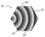
도 10은 광 투과성 구조체(30)의 마이크로프리즘(82)의 어레이(80)의 실시예의 부감도를 예시하고, 도 11은 반복 패턴(90)의 마이크로프리즘(82)의 어레이(80)를 예시한다. 예시된 바와 같이, 흰색은 마이크로프리즘(82)의 표면에서 보다 높은 지점을 나타내고, 보다 어두운 색상은 마이크로프리즘(82)의 표면에서 보다 낮은 지점을 나타낸다. 마이크로프리즘(82)은 상이한 크기의 곡선형이고, 육각형 형상(83)을 대략적으로 채우도록 포개진다. 각각의 마이크로프리즘(82)은 약 40도의 경사 각도(85)로 배치된 제1 표면(84) 및 약 70도의 경사 각도(87)로 배치된 제2 표면(86)을 갖는다. 제1 표면(84)과 제2 표면(86) 사이의 피크 각도(89)는 약 70도이다. 제2 표면(86)은 제1 표면(84)의 경사 각도보다 큰 경사 각도(87), 및 제2 표면에 수직인 방향(N)에서 광 투과성 구조체(30)의 외부로부터 보았을 때 볼록한 곡률을 갖는다. 육각형 형상(83)은 크기(평탄한 변-평탄한 변)가 약 270 μm일 수 있고 도 10에 부분적으로 도시된 바와 같이 기판(32)의 표면에 걸쳐 반복될 수 있다. 이 치수는 단지 예로서 제공된 것으로 의도되고 육각형 형상(83)은 크기가 더 크거나 더 작을 수 있음을 이해해야 한다. 다른 실시예에서, 포개진 곡선형 마이크로프리즘(82)은 육각형(83)과 다른 형상을 채우도록 배치될 수 있다. 예를 들어, 다른 실시예에서, 포개진 곡선형 마이크로프리즘(82)은 정사각형, 마름모꼴 또는 반복 패턴으로 복제될 수 있는 임의의 다른 원하는 형상을 채우도록 배치될 수 있다.10 illustrates an overhead view of an embodiment of an
본 명세서에 설명된 임의의 실시예에 따른 광 투과성 구조체는 본 기술 분야에 공지된 많은 기술을 사용하여 생성될 수 있다. 예를 들어, 일 실시예에서, 프리즘의 형상은 적절한 마스터 몰드, 및 열 경화성 폴리머 또는 자외선(UV) 광 경화성 폴리머를 사용하여 기판 상에 캐스팅될 수 있거나, 또는 그 형상은 압축 성형 또는 다른 성형을 통해 열가소성 기판으로 임프레싱될 수 있거나, 또는 압출 엠보싱 또는 사출 성형을 사용하여 기판과 동시에 생성될 수 있다. 마이크로프리즘은 마스터를 복제함으로써 생성될 수 있다. 예를 들어, 광 확산기는, 발명의 명칭이 "Systems And Methods for Fabricating Optical Microstructures Using a Cylindrical Platform and a Rastered Radiation Beam"인 Rinehart 등의 미국 특허 제7,190,387 B2호; 발명의 명칭이 "Methods for Mastering Microstructures Through a Substrate Using Negative Photoresist"인 Freese 등의 미국 특허 제7,867,695 B2호; 및/또는 발명의 명칭이 "Methods for Fabricating Microstructures by Imaging a Radiation Sensitive Layer Sandwiched Between Outer Layers"이고 본 발명의 양수인에게 양도된, Wood 등의 미국 특허 제7,192,692 B2호에 설명된 바와 같이 원하는 형상을 포함하는 마스터의 복제에 의해 제조될 수 있고, 이들 특허 모두의 개시내용은 본 명세서에 완전히 기재된 것처럼 그 전체가 본 명세서에 참조로 포함된다. 마스터 자체는 이들 특허에 설명된 레이저 스캐닝 기술을 사용하여 제조될 수 있고, 또한 이들 특허에 설명된 복제 기술을 사용하여 확산기를 제공하도록 복제될 수 있다.Light transmissive structures according to any of the embodiments described herein can be produced using many techniques known in the art. For example, in one embodiment, the shape of the prism can be cast on a substrate using a suitable master mold, and a heat curable polymer or an ultraviolet (UV) photocurable polymer, or the shape can be compression molded or other molded. It can be impressed into the thermoplastic substrate or can be produced simultaneously with the substrate using extrusion embossing or injection molding. Microprisms can be created by duplicating a master. For example, a light diffuser is disclosed in US Pat. No. 7,190,387 B2 to Rinehart et al., Entitled "Systems And Methods for Fabricating Optical Microstructures Using a Cylindrical Platform and a Rastered Radiation Beam"; US Patent No. 7,867,695 B2 to Freese et al., Entitled "Methods for Mastering Microstructures Through a Substrate Using Negative Photoresist"; And / or include the desired shape as described in US Pat. No. 7,192,692 B2 to Wood et al., Entitled "Methods for Fabricating Microstructures by Imaging a Radiation Sensitive Layer Sandwiched Between Outer Layers" and assigned to the assignee of the present invention. And the disclosures of all these patents are incorporated herein by reference in their entirety, as if fully set forth herein. The master itself can be manufactured using the laser scanning techniques described in these patents, and can also be replicated to provide a diffuser using the replication techniques described in these patents.
일 실시예에서, 본 기술 분야에 공지된 레이저 홀로그래피는 감광성 재료에 원하는 마이크로프리즘을 생성하는 홀로그래픽 패턴을 생성하는 데에 사용될 수 있다. 일 실시예에서, 반도체, 디스플레이, 회로 기판, 및 본 기술 분야에 공지된 다른 일반적인 기술에 사용되는 것과 같은 투영 또는 접촉 포토리소그래피는 마이크로프리즘을 감광성 재료에 노출시키는 데에 사용될 수 있다. 일 실시예에서, 마스크를 사용하거나 집속되고 변조된 레이저 빔을 사용하는 레이저 절제가 재료에 표시를 포함하는 마이크로프리즘을 생성하는 데에 사용될 수 있다. 일 실시예에서, 본 기술 분야에 공지된 미세 가공(다이아몬드 가공으로도 공지됨)은 고체 재료로부터 원하는 마이크로프리즘을 생성하는 데에 사용될 수 있다. 일 실시예에서, 본 기술 분야에 공지된 적층 제조(3D 인쇄로도 공지됨)는 고체 재료에서 원하는 마이크로프리즘을 생성하는 데에 사용될 수 있다.In one embodiment, laser holography known in the art can be used to create holographic patterns that produce the desired microprisms in the photosensitive material. In one embodiment, projection or contact photolithography, such as used in semiconductors, displays, circuit boards, and other general techniques known in the art, can be used to expose microprisms to photosensitive materials. In one embodiment, laser ablation using a mask or using a focused and modulated laser beam can be used to create a microprism that includes an indication in the material. In one embodiment, micromachining (also known as diamond machining) known in the art can be used to produce the desired microprism from a solid material. In one embodiment, additive manufacturing known in the art (also known as 3D printing) can be used to produce the desired microprisms in solid materials.
도 12는 도 8에 예시된 마이크로프리즘(62)의 어레이(60)를 갖는 광 투과성 구조체(30)를 통과하는 120도 FWHM 소스 분포를 갖는 램버시안 광원을 사용하여 측정된 벤딩 평면에서의 광 분포를 예시한다. 도 12는 벤딩 방향으로부터 0도에서 90도까지 광의 매끄럽고 단조로운 감소를 도시한다. 또한, 광 투과성 구조체(30)는 전술한 종래 기술의 필름과 비교하여 광의 벤딩을 더 강하게 하거나 증가시키는 것으로 보인다.FIG. 12 shows light distribution in the bending plane measured using a Lambertian light source having a 120 degree FWHM source distribution through a
도 13은 도 8에 예시된 마이크로프리즘(62)의 어레이(60)를 갖는 광 투과성 구조체(30)를 통과하는 80도 FWHM 소스 분포를 갖는 광원을 사용하여 측정된 벤딩 평면에서의 광 분포를 예시한다. 도 13은 벤딩 방향으로부터 0도에서 90도까지 광의 단조로운 감소를 도시한다. 또한, 광 투과성 구조체(30)는 전술한 종래 기술의 필름과 비교하여 광의 벤딩을 더 강하게 하거나 증가시키는 것으로 보인다.FIG. 13 illustrates the light distribution in the bending plane measured using a light source having an 80 degree FWHM source distribution through a
도 14는 광원으로부터 직접 하향으로 연장되는 방향(0°에 대응)에 대해 10도 만큼 경사진 10도 FWHM을 갖는 광원으로부터 방출된 광의 소스 분포를 예시한다. 예시된 바와 같이, 분포는 경사 방향에 대해 대체로 대칭이다.FIG. 14 illustrates a source distribution of light emitted from a light source having a 10 degree FWHM tilted by 10 degrees with respect to a direction extending directly downward from the light source (corresponding to 0 °). As illustrated, the distribution is generally symmetrical with respect to the oblique direction.
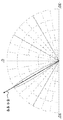
도 15는 도 14의 소스 분포가 루미닛 방향 전환 필름을 통과한 후 벤딩 평면에서의 광 분포를 예시한다. 예시된 바와 같이, 루미닛 방향 전환 필름은 일반적으로 경사 방향으로부터 약 +20°인 벤딩 방향으로 광을 재분배하지만, 또한 대체로 경사 방향으로부터 약 -20°의 각도로 지향되는 원하지 않는 2차 분포(100)를 생성한다.FIG. 15 illustrates the light distribution in the bending plane after the source distribution of FIG. 14 passes through the laminate redirecting film. As illustrated, the laminate redirecting film redistributes light in the bending direction, which is generally about + 20 ° from the oblique direction, but also generally has an unwanted secondary distribution (100) directed at an angle of about -20 ° from the oblique direction. )
도 16은 도 14의 소스 분포가 도 8의 마이크로프리즘(62)의 어레이(60)를 갖는 광 투과성 구조체(30)를 통과한 후 벤딩 평면에서의 광 분포를 예시한다. 예시된 바와 같이, 광 투과성 구조체(30)는 경사 방향으로부터 약 +20°인 벤딩 방향으로 광을 재분배하고 어떠한 2차 분포도 생성하지 않는다.FIG. 16 illustrates the light distribution in the bending plane after the source distribution of FIG. 14 passes through the
도 17은 광원으로부터 직접 하향으로 연장되는 방향(0°에 대응)에 대해 30도 만큼 경사진 10도 FWHM을 갖는 광원으로부터 방출된 광의 소스 분포를 예시한다. 예시된 바와 같이, 분포는 경사 방향에 대해 대체로 대칭이다.FIG. 17 illustrates a source distribution of light emitted from a light source having a 10 degree FWHM tilted by 30 degrees with respect to a direction extending directly downward from the light source (corresponding to 0 °). As illustrated, the distribution is generally symmetrical with respect to the oblique direction.
도 18은 도 17의 소스 분포가 루미닛 방향 전환 필름을 통과한 후 벤딩 평면에서의 광 분포를 예시한다. 예시된 바와 같이, 루미닛 방향 전환 필름은 일반적으로 경사 방향으로부터 약 +20°보다 큰 벤딩 방향으로 광을 재분배하지만, 또한 대체로 경사 방향으로부터 약 -60°보다 큰 각도로 지향되는 원하지 않는 2차 분포(110)를 생성한다.FIG. 18 illustrates the light distribution in the bending plane after the source distribution of FIG. 17 passes through the laminate redirecting film. As illustrated, the laminate redirecting film generally redistributes light in a bending direction greater than about + 20 ° from the oblique direction, but also generally has an undesired secondary distribution directed at an angle greater than about -60 ° from the oblique direction.
도 19는 도 17의 소스 분포가 도 8의 마이크로프리즘(62)의 어레이(60)를 갖는 광 투과성 구조체(30)를 통과한 후 벤딩 평면에서의 광 분포를 예시한다. 예시된 바와 같이, 광 투과성 구조체(30)는 경사 방향으로부터 +20°보다 큰 벤딩 방향으로 광을 재분배하고 어떠한 2차 분포도 생성하지 않는다.FIG. 19 illustrates the light distribution in the bending plane after the source distribution of FIG. 17 passes through the
본 명세서에 설명된 실시예는 다수의 가능한 구현 및 예를 나타내며, 본 개시내용을 반드시 임의의 특정 실시예로 제한하도록 의도되지 않는다. 대신에, 이들 실시예에 대해 다양한 수정이 이루어질 수 있으며, 본 명세서에 설명된 다양한 실시예의 상이한 조합은 명백히 설명되지 않았더라도 본 기술 분야의 숙련자에 의해 이해되는 바와 같이 본 발명의 일부로서 사용될 수 있다. 임의의 그러한 수정은 본 개시내용의 사상 및 범위 내에 포함되고 아래의 청구범위에 의해 보호되도록 의도된다.The embodiments described herein represent a number of possible implementations and examples, and are not intended to necessarily limit the present disclosure to any particular embodiment. Instead, various modifications may be made to these embodiments, and different combinations of the various embodiments described herein may be used as part of the invention, as would be understood by one of ordinary skill in the art, even if not explicitly described. . Any such modifications are intended to be included within the spirit and scope of the disclosure and protected by the following claims.
Claims (30)
대향하는 제1 및 제2 면을 갖는 광 투과성 기판; 및
제1 면 상의 마이크로프리즘 요소의 어레이를 포함하고,
각각의 마이크로프리즘 요소는 제2 면에 대해 제1 경사 각도로 배치된 제1 경사 표면, 및 제2 면에 대해 제2 경사 각도로 배치된 제2 경사 표면을 포함하며, 제1 경사 각도는 제2 경사 각도보다 작고, 제1 경사 표면과 제2 경사 표면 사이의 피크 각도는 약 70도 내지 약 100도의 범위에 있으며, 제2 경사 표면은 이에 대해 수직인 각도에서 보았을 때 볼록한 곡률을 갖고,
광 투과성 구조체는 제1 면과 대면하는 광원으로부터 방출된 광을 제1 방향으로 수신하고 제2 면으로부터 나오는 광을 제1 방향과 상이한 제2 방향으로 재분배하도록 구성되는, 광 투과성 구조체.It is a light transmissive structure,
A light transmissive substrate having opposing first and second faces; And
An array of microprism elements on the first face,
Each microprism element includes a first inclined surface disposed at a first inclined angle with respect to the second face, and a second inclined surface disposed at a second inclined angle with respect to the second face, wherein the first inclined angle is defined as a first inclined angle. Less than two inclination angles, the peak angle between the first inclined surface and the second inclined surface is in the range of about 70 degrees to about 100 degrees, and the second inclined surface has a convex curvature when viewed at an angle perpendicular to it;
The light transmissive structure is configured to receive light emitted from a light source facing the first face in a first direction and to redistribute light exiting from the second face in a second direction different from the first direction.
광원; 및
상기 광원으로부터 이격된 광 투과성 구조체를 포함하고,
상기 광 투과성 구조체는,
광 투과성 기판으로서, 상기 광원과 대면하는 제1 면 및 제1 면과 광 투과성 기판의 반대쪽에 있는 제2 면을 갖는, 광 투과성 기판, 및
제1 면 상의 마이크로프리즘 요소의 어레이를 포함하고, 각각의 마이크로프리즘 요소는 제2 면에 대해 제1 경사 각도로 배치된 제1 경사 표면, 및 제2 면에 대해 제2 경사 각도로 배치된 제2 경사 표면을 포함하며, 제1 경사 각도는 제2 경사 각도보다 작고, 제1 경사 표면과 제2 경사 표면 사이의 피크 각도는 약 70도 내지 약 100도의 범위에 있으며, 제2 경사 표면은 이에 대해 수직인 각도에서 보았을 때 볼록한 곡률을 갖고,
상기 광 투과성 구조체는 광원으로부터 방출된 광을 제1 방향으로 수신하고 제2 면으로부터 나오는 광을 제1 방향과 상이한 제2 방향으로 재분배하도록 구성되는, 조명 시스템.Lighting system,
Light source; And
A light transmissive structure spaced from the light source,
The light transmissive structure,
A light transmissive substrate, the light transmissive substrate having a first face facing the light source and a second face opposite to the first face and the light transmissive substrate, and
An array of microprism elements on a first face, each microprism element having a first slanted surface disposed at a first tilt angle with respect to the second face, and a first tilted surface disposed at a second tilt angle with respect to the second face. A second inclined surface, wherein the first inclined angle is less than the second inclined angle, the peak angle between the first inclined surface and the second inclined surface is in the range of about 70 degrees to about 100 degrees, and the second inclined surface is Has a convex curvature when viewed from a normal angle to
And the light transmissive structure is configured to receive light emitted from the light source in a first direction and redistribute light exiting from the second side in a second direction different from the first direction.
Applications Claiming Priority (3)
| Application Number | Priority Date | Filing Date | Title |
|---|---|---|---|
| US201762527573P | 2017-06-30 | 2017-06-30 | |
| US62/527,573 | 2017-06-30 | ||
| PCT/US2018/040268 WO2019006288A1 (en) | 2017-06-30 | 2018-06-29 | Light transmissive structures for redistribution of light and lighting systems including same |
Publications (1)
| Publication Number | Publication Date |
|---|---|
| KR20200026909A true KR20200026909A (en) | 2020-03-11 |
Family
ID=64742236
Family Applications (1)
| Application Number | Title | Priority Date | Filing Date |
|---|---|---|---|
| KR1020207002382A KR20200026909A (en) | 2017-06-30 | 2018-06-29 | Lighting system comprising a light transmissive structure and a light transmissive structure for redistribution of light |
Country Status (6)
| Country | Link |
|---|---|
| US (2) | US11300268B2 (en) |
| EP (1) | EP3645937B1 (en) |
| JP (2) | JP2020526874A (en) |
| KR (1) | KR20200026909A (en) |
| CN (1) | CN110998176B (en) |
| WO (1) | WO2019006288A1 (en) |
Cited By (1)
| Publication number | Priority date | Publication date | Assignee | Title |
|---|---|---|---|---|
| US11885485B2 (en) | 2017-06-30 | 2024-01-30 | Brightview Technologies, Inc. | Light transmissive structures for redistribution of light and lighting systems including same |
Families Citing this family (1)
| Publication number | Priority date | Publication date | Assignee | Title |
|---|---|---|---|---|
| KR20230117438A (en) | 2020-12-18 | 2023-08-08 | 브라이트뷰 테크놀로지즈 아이엔씨. | Edge-lit back light unit with improved efficiency |
Family Cites Families (23)
| Publication number | Priority date | Publication date | Assignee | Title |
|---|---|---|---|---|
| IT1289716B1 (en) * | 1996-12-05 | 1998-10-16 | Fiat Ricerche | LIGHTING DEVICE SUITABLE TO GENERATE A RECTANGULAR PATTERN IN THE WORKING AREA, FOR EXAMPLE FOR THE LIGHTING OF STRIPS |
| JP3542329B2 (en) * | 1998-09-16 | 2004-07-14 | 富士通株式会社 | Optical device and display device using the same |
| US7364341B2 (en) * | 1999-02-23 | 2008-04-29 | Solid State Opto Limited | Light redirecting films including non-interlockable optical elements |
| US6752505B2 (en) | 1999-02-23 | 2004-06-22 | Solid State Opto Limited | Light redirecting films and film systems |
| KR100432438B1 (en) * | 2001-01-18 | 2004-05-22 | 주식회사 송산 | Prism Diffuser |
| US7192692B2 (en) | 2003-09-11 | 2007-03-20 | Bright View Technologies, Inc. | Methods for fabricating microstructures by imaging a radiation sensitive layer sandwiched between outer layers |
| US7867695B2 (en) | 2003-09-11 | 2011-01-11 | Bright View Technologies Corporation | Methods for mastering microstructures through a substrate using negative photoresist |
| US7190387B2 (en) | 2003-09-11 | 2007-03-13 | Bright View Technologies, Inc. | Systems for fabricating optical microstructures using a cylindrical platform and a rastered radiation beam |
| US8619363B1 (en) * | 2007-11-06 | 2013-12-31 | Fusion Optix, Inc. | Light redirecting element comprising a forward diffracting region and a scattering region |
| DE102007059732B4 (en) * | 2007-12-12 | 2020-11-12 | Pictiva Displays International Limited | Light emitting device |
| US20110128470A1 (en) | 2008-04-17 | 2011-06-02 | Jun Yorita | Light distribution control panel, display device for mounting on mobile unit, light distribution control sheet, optical component, lighting device, and display device |
| CN101963326B (en) * | 2009-07-23 | 2012-03-14 | 富士迈半导体精密工业(上海)有限公司 | Reflector and lighting device |
| CN102859272B (en) | 2010-04-30 | 2014-01-08 | 潘定国 | Light guide plate with micro prisms, manufacture methode thereof and plate-shape lamp and plate-shape lamp fixture made thereby |
| JP2012069282A (en) * | 2010-09-21 | 2012-04-05 | Sumitomo Chemical Co Ltd | Optical sheet, plane light source device, and transmission image display device |
| JP5131791B2 (en) | 2011-03-14 | 2013-01-30 | 学校法人 関西大学 | Condensing film and solar cell module |
| GB2516967A (en) * | 2013-08-09 | 2015-02-11 | Iq Structures Sro | Autostereoscopic prismatic printing rasters |
| WO2015062863A1 (en) | 2013-10-29 | 2015-05-07 | Koninklijke Philips N.V. | Lighting unit, especially for road illumination |
| US10317583B2 (en) * | 2013-12-19 | 2019-06-11 | Bright View Technologies Corporation | 2D deglaring diffusers increasing axial luminous intensity |
| US9746604B2 (en) * | 2014-01-06 | 2017-08-29 | Agira, Inc. | Light guide apparatus and fabrication method thereof |
| RU2660919C1 (en) | 2014-02-04 | 2018-07-11 | Шарп Кабусики Кайся | Lighting element, a lighting device and a method for mounting the lighting device |
| CN108603746B (en) * | 2016-02-10 | 2020-03-27 | 恩普乐股份有限公司 | Marker device |
| CN106646720A (en) * | 2016-11-16 | 2017-05-10 | 华南理工大学 | Double-surface anisotropic concentric arc curved distributed micro prism array light guide plate |
| JP2020526874A (en) | 2017-06-30 | 2020-08-31 | ブライト ヴュー テクノロジーズ コーポレーションBright View Technologies Corporation | Light-transmitting structure for redistribution of light and lighting system containing it |
-
2018
- 2018-06-29 JP JP2019571741A patent/JP2020526874A/en active Pending
- 2018-06-29 KR KR1020207002382A patent/KR20200026909A/en not_active Application Discontinuation
- 2018-06-29 US US16/625,830 patent/US11300268B2/en active Active
- 2018-06-29 WO PCT/US2018/040268 patent/WO2019006288A1/en unknown
- 2018-06-29 CN CN201880048811.5A patent/CN110998176B/en active Active
- 2018-06-29 EP EP18824408.1A patent/EP3645937B1/en active Active
-
2022
- 2022-03-22 US US17/700,990 patent/US11885485B2/en active Active
-
2023
- 2023-08-18 JP JP2023133439A patent/JP2023159281A/en active Pending
Cited By (1)
| Publication number | Priority date | Publication date | Assignee | Title |
|---|---|---|---|---|
| US11885485B2 (en) | 2017-06-30 | 2024-01-30 | Brightview Technologies, Inc. | Light transmissive structures for redistribution of light and lighting systems including same |
Also Published As
| Publication number | Publication date |
|---|---|
| JP2023159281A (en) | 2023-10-31 |
| EP3645937A1 (en) | 2020-05-06 |
| CN110998176B (en) | 2023-05-02 |
| US11885485B2 (en) | 2024-01-30 |
| US20210156539A1 (en) | 2021-05-27 |
| WO2019006288A1 (en) | 2019-01-03 |
| EP3645937B1 (en) | 2024-03-06 |
| JP2020526874A (en) | 2020-08-31 |
| US11300268B2 (en) | 2022-04-12 |
| EP3645937A4 (en) | 2021-03-24 |
| CN110998176A (en) | 2020-04-10 |
| US20220214023A1 (en) | 2022-07-07 |
Similar Documents
| Publication | Publication Date | Title |
|---|---|---|
| US9765949B2 (en) | Shaped microstructure-based optical diffusers for creating batwing and other lighting patterns | |
| US10072816B2 (en) | Microstructure-based optical diffusers for creating batwing and other lighting patterns | |
| US10302275B2 (en) | Microstructure-based diffusers for creating batwing lighting patterns | |
| US11885485B2 (en) | Light transmissive structures for redistribution of light and lighting systems including same | |
| US20160161663A1 (en) | Dual-sided film with compound prisms | |
| JP7436369B2 (en) | Microstructure that converts light with Lambertian distribution into batwing distribution | |
| US11499683B2 (en) | Micro-structured optical sheet and panel light assembly using same | |
| KR20120056016A (en) | Illuminating apparatus with reduced glare | |
| US20120219277A1 (en) | Luminaire, Camera or Camcorder Having Same and Optical Element for a Luminaire | |
| RU186640U1 (en) | OPTICAL DEVICE FOR MODIFICATION OF LIGHT DISTRIBUTION SCHEME | |
| RU2700182C2 (en) | Tubular light-emitting device | |
| JP2015141766A (en) | illumination device and Fresnel lens sheet | |
| WO2018172149A1 (en) | High visual comfort road and urban led lighting | |
| TWI677645B (en) | Illumination device | |
| US11946608B1 (en) | Asymmetric collimator | |
| WO2015195160A1 (en) | Microstructure-based diffusers for creating batwing lighting patterns | |
| JP2011054333A (en) | Lighting device and lighting system | |
| JP6213805B2 (en) | Illuminated mirror device | |
| JP2015035412A (en) | Lighting device | |
| JP2015141768A (en) | illumination device and Fresnel lens sheet | |
| JP2010135146A (en) | Luminaire | |
| JP2010218723A (en) | Luminaire |
Legal Events
| Date | Code | Title | Description |
|---|---|---|---|
| A201 | Request for examination | ||
| E902 | Notification of reason for refusal |