KR20200026517A - Low Noise Cable For Charger and Discharger - Google Patents
Low Noise Cable For Charger and Discharger Download PDFInfo
- Publication number
- KR20200026517A KR20200026517A KR1020180104549A KR20180104549A KR20200026517A KR 20200026517 A KR20200026517 A KR 20200026517A KR 1020180104549 A KR1020180104549 A KR 1020180104549A KR 20180104549 A KR20180104549 A KR 20180104549A KR 20200026517 A KR20200026517 A KR 20200026517A
- Authority
- KR
- South Korea
- Prior art keywords
- cable
- insulating member
- current low
- charging
- discharging
- Prior art date
Links
Images


Classifications
-
- H—ELECTRICITY
- H01—ELECTRIC ELEMENTS
- H01B—CABLES; CONDUCTORS; INSULATORS; SELECTION OF MATERIALS FOR THEIR CONDUCTIVE, INSULATING OR DIELECTRIC PROPERTIES
- H01B7/00—Insulated conductors or cables characterised by their form
- H01B7/02—Disposition of insulation
-
- H—ELECTRICITY
- H01—ELECTRIC ELEMENTS
- H01B—CABLES; CONDUCTORS; INSULATORS; SELECTION OF MATERIALS FOR THEIR CONDUCTIVE, INSULATING OR DIELECTRIC PROPERTIES
- H01B3/00—Insulators or insulating bodies characterised by the insulating materials; Selection of materials for their insulating or dielectric properties
- H01B3/18—Insulators or insulating bodies characterised by the insulating materials; Selection of materials for their insulating or dielectric properties mainly consisting of organic substances
- H01B3/30—Insulators or insulating bodies characterised by the insulating materials; Selection of materials for their insulating or dielectric properties mainly consisting of organic substances plastics; resins; waxes
- H01B3/302—Polyurethanes or polythiourethanes; Polyurea or polythiourea
-
- H—ELECTRICITY
- H01—ELECTRIC ELEMENTS
- H01B—CABLES; CONDUCTORS; INSULATORS; SELECTION OF MATERIALS FOR THEIR CONDUCTIVE, INSULATING OR DIELECTRIC PROPERTIES
- H01B3/00—Insulators or insulating bodies characterised by the insulating materials; Selection of materials for their insulating or dielectric properties
- H01B3/18—Insulators or insulating bodies characterised by the insulating materials; Selection of materials for their insulating or dielectric properties mainly consisting of organic substances
- H01B3/30—Insulators or insulating bodies characterised by the insulating materials; Selection of materials for their insulating or dielectric properties mainly consisting of organic substances plastics; resins; waxes
- H01B3/42—Insulators or insulating bodies characterised by the insulating materials; Selection of materials for their insulating or dielectric properties mainly consisting of organic substances plastics; resins; waxes polyesters; polyethers; polyacetals
- H01B3/421—Polyesters
-
- H—ELECTRICITY
- H01—ELECTRIC ELEMENTS
- H01B—CABLES; CONDUCTORS; INSULATORS; SELECTION OF MATERIALS FOR THEIR CONDUCTIVE, INSULATING OR DIELECTRIC PROPERTIES
- H01B3/00—Insulators or insulating bodies characterised by the insulating materials; Selection of materials for their insulating or dielectric properties
- H01B3/18—Insulators or insulating bodies characterised by the insulating materials; Selection of materials for their insulating or dielectric properties mainly consisting of organic substances
- H01B3/30—Insulators or insulating bodies characterised by the insulating materials; Selection of materials for their insulating or dielectric properties mainly consisting of organic substances plastics; resins; waxes
- H01B3/44—Insulators or insulating bodies characterised by the insulating materials; Selection of materials for their insulating or dielectric properties mainly consisting of organic substances plastics; resins; waxes vinyl resins; acrylic resins
- H01B3/443—Insulators or insulating bodies characterised by the insulating materials; Selection of materials for their insulating or dielectric properties mainly consisting of organic substances plastics; resins; waxes vinyl resins; acrylic resins from vinylhalogenides or other halogenoethylenic compounds
-
- H—ELECTRICITY
- H01—ELECTRIC ELEMENTS
- H01B—CABLES; CONDUCTORS; INSULATORS; SELECTION OF MATERIALS FOR THEIR CONDUCTIVE, INSULATING OR DIELECTRIC PROPERTIES
- H01B7/00—Insulated conductors or cables characterised by their form
- H01B7/02—Disposition of insulation
- H01B7/0208—Cables with several layers of insulating material
- H01B7/0216—Two layers
-
- H—ELECTRICITY
- H01—ELECTRIC ELEMENTS
- H01B—CABLES; CONDUCTORS; INSULATORS; SELECTION OF MATERIALS FOR THEIR CONDUCTIVE, INSULATING OR DIELECTRIC PROPERTIES
- H01B7/00—Insulated conductors or cables characterised by their form
- H01B7/02—Disposition of insulation
- H01B7/0291—Disposition of insulation comprising two or more layers of insulation having different electrical properties
-
- H—ELECTRICITY
- H01—ELECTRIC ELEMENTS
- H01B—CABLES; CONDUCTORS; INSULATORS; SELECTION OF MATERIALS FOR THEIR CONDUCTIVE, INSULATING OR DIELECTRIC PROPERTIES
- H01B7/00—Insulated conductors or cables characterised by their form
- H01B7/17—Protection against damage caused by external factors, e.g. sheaths or armouring
- H01B7/29—Protection against damage caused by extremes of temperature or by flame
- H01B7/295—Protection against damage caused by extremes of temperature or by flame using material resistant to flame
-
- H—ELECTRICITY
- H01—ELECTRIC ELEMENTS
- H01B—CABLES; CONDUCTORS; INSULATORS; SELECTION OF MATERIALS FOR THEIR CONDUCTIVE, INSULATING OR DIELECTRIC PROPERTIES
- H01B7/00—Insulated conductors or cables characterised by their form
- H01B7/32—Insulated conductors or cables characterised by their form with arrangements for indicating defects, e.g. breaks or leaks
-
- H—ELECTRICITY
- H01—ELECTRIC ELEMENTS
- H01B—CABLES; CONDUCTORS; INSULATORS; SELECTION OF MATERIALS FOR THEIR CONDUCTIVE, INSULATING OR DIELECTRIC PROPERTIES
- H01B9/00—Power cables
- H01B9/003—Power cables including electrical control or communication wires
-
- H—ELECTRICITY
- H01—ELECTRIC ELEMENTS
- H01B—CABLES; CONDUCTORS; INSULATORS; SELECTION OF MATERIALS FOR THEIR CONDUCTIVE, INSULATING OR DIELECTRIC PROPERTIES
- H01B9/00—Power cables
- H01B9/006—Constructional features relating to the conductors
-
- H—ELECTRICITY
- H01—ELECTRIC ELEMENTS
- H01B—CABLES; CONDUCTORS; INSULATORS; SELECTION OF MATERIALS FOR THEIR CONDUCTIVE, INSULATING OR DIELECTRIC PROPERTIES
- H01B9/00—Power cables
- H01B9/02—Power cables with screens or conductive layers, e.g. for avoiding large potential gradients
Abstract
Description
본 발명은 충·방전기용 대전류 저노이즈 케이블에 관한 것으로, 더욱 상세하게는 케이블 상호간의 전기적인 유도로 인해 발생하는 노이즈 영향을 최소화하고, 케이블의 부피도 줄일 수 있는 충·방전기용 대전류 저노이즈 케이블에 관한 것이다.The present invention relates to a large current low noise cable for charging and discharging, and more particularly, to a large current low noise cable for charging and discharging which can minimize the noise effect caused by electrical induction between cables and reduce the volume of the cable. will be.
전기 케이블(cable)에 노이즈(noise)가 발생하는 경우, 전기 공급 품질의 하락으로 인해 장치에 오작동이나 장애를 일으킬 수 있다. 전기 케이블에는 내부적 요인 및 외부적 요인에 의해 여러가지 노이즈가 발생할 수 있다. 예를 들어, 복수의 케이블이 인접하는 경우 케이블 상호간의 유도 현상에 의해 케이블에 노이즈가 발생할 수 있으며, 이는 케이블 상호 간의 용량성 결합과 유도성 결합에 의하여 발생할 수 있다.If noise occurs in the cable, a decrease in the quality of the electrical supply can cause the device to malfunction or fail. In electrical cables, various noises may occur due to internal and external factors. For example, when a plurality of cables are adjacent to each other, noise may occur in the cable due to induction between the cables, which may be caused by capacitive coupling and inductive coupling between the cables.
용량성 결합에 의한 전기 노이즈를 감소시키기 위해서는 케이블 상호간의 작용정전용량을 최소화 해야 한다. 예를 들어, 용량성 결합에 의한 전기 노이즈를 감소시킬 수 있는 방법으로 케이블간의 이격거리를 증가시키거나, 케이블 사이에 차폐망 또는 접지된 격벽을 설치하는 방법 등이 있다.To reduce the electrical noise caused by capacitive coupling, the operating capacitance between the cables must be minimized. For example, a method of reducing electrical noise by capacitive coupling may include increasing a separation distance between cables, or installing a shielding network or a grounded partition between the cables.
유도성 결합에 의한 전기 노이즈를 감소시키기 위한 가장 보편적인 방법은 보호하고자 하는 케이블에 트위스트 페어(Twisted Pair)를 사용하는 것이다. 트위스트 페어(Twisted Pair)를 사용하는 경우, 케이블 내 도선간 기전력을 서로 상쇄시킬 수 있으며, 잡음 자속에 의하여 케이블 양단간에 유기되는 전압을 상대적으로 평형이 되게 함으로써 전기 노이즈를 감소시킬 수 있다.The most common way to reduce electrical noise by inductive coupling is to use twisted pairs for the cables to be protected. When a twisted pair is used, the electromotive force between the conductors in the cable can be canceled with each other, and the electrical noise can be reduced by relatively balancing the voltage induced between the cables by the noise magnetic flux.
도 1은 트위스트 페어 케이블에서 기전력 상쇄로 인한 유도성 결합 감소를 설명하는 도면이다.1 is a diagram illustrating inductive coupling reduction due to electromotive force cancellation in twisted pair cable.
도 1에 도시된 바와 같이 자속의 방향이 지면쪽으로 향할때 케이블에는 실선 화살표와 같이 기전력이 발생한다. 따라서, 트위스트 페어 케이블의 경우, 각 부분에서 서로 반대 방향의 기전력이 발생되어 서로 상쇄되고 유도성 결합이 감소될 수 있다.As shown in FIG. 1, when the magnetic flux is directed toward the ground, electromotive force is generated in the cable as shown by the solid arrow. Thus, in the case of a twisted pair cable, electromotive force in opposite directions can be generated at each part to cancel each other and reduce inductive coupling.
케이블의 용량이 커질수록 케이블을 구성하는 선의 두께가 커지게 된다. 고용량의 케이블의 경우에도, 트위스트 페어를 사용하면 기전력이 상쇄되어 노이즈에 민감하지 않게 된다. 그러나, 고용량 케이블은 부피가 크기 때문에 일정하게 트위스트 하는 것이 어렵고, 트위스트 형태를 유지하는 것도 힘들다. 또한, 고용량 케이블의 경우 트위스트 페어를 사용하게 되면 케이블의 부피도 증가하는 문제가 있다.
As the capacity of the cable increases, the thickness of the wire constituting the cable increases. Even for high capacity cables, the use of twisted pairs cancels the electromotive force and makes it insensitive to noise. However, high capacity cables are bulky, which makes it difficult to twist constantly and maintain a twisted shape. In addition, in the case of a high-capacity cable, when the twisted pair is used, there is a problem that the volume of the cable also increases.
본 발명은 케이블 상호간의 전기적인 유도로 인해 발생하는 노이즈 영향을 최소화하여 케이블의 송전 성능을 높일 수 있는 충·방전기용 대전류 저노이즈 케이블을 제공한다.The present invention provides a high-current low-noise cable for charging and discharging that can increase the transmission performance of the cable by minimizing the noise effect caused by the electrical induction between the cables.
본 발명은 노이즈 감소와 함께 기존의 고용량 케이블보다 부피가 작으면서 일정하게 형태를 유지할 수 있는 충·방전기용 대전류 저노이즈 케이블을 제공한다.The present invention provides a high-current low-noise cable for charging and discharging, which can maintain a constant shape while reducing the volume and with a smaller volume than a conventional high capacity cable.
본 발명은 구성 요소를 단순화하여 생산과 유지보수를 용이하게 할 수 있는 충·방전기용 대전류 저노이즈 케이블을 제공한다.
The present invention provides a high-current low-noise cable for charger and discharger that can simplify the components and facilitate production and maintenance.
본 발명에 따른 충·방전기용 대전류 저노이즈 케이블은 양극 선, 상기 양극 선의 외측을 둘러싸는 제1 절연부재, 상기 제1 절연부재의 외측을 둘러싸는 음극 선 및 상기 음극 선의 외측을 둘러싸는 제2 절연부재를 포함한다.The high current low noise cable for charging and discharging according to the present invention includes a positive electrode wire, a first insulating member surrounding the outside of the positive electrode line, a negative electrode surrounding the outside of the first insulating member, and a second insulation surrounding the outside of the negative electrode line. Member.
일 실시예에서, 상기 충·방전기용 대전류 저노이즈 케이블은 상기 음극 선과 상기 제2 절연부재 사이에 위치하는 양극 센싱(sensing)도선 및 음극 센싱(sensing)도선을 더 포함할 수 있다.In one embodiment, the high-current low-noise cable for charging and discharging may further include an anode sensing lead and a cathode sensing lead disposed between the cathode line and the second insulation member.
일 실시예에서, 상기 양극 센싱도선과 음극 센싱도선은 꼬아져서(twisted) 상기 케이블의 길이 방향으로 연장될 수 있다.In one embodiment, the anode sensing lead and the cathode sensing lead may be twisted and extend in the longitudinal direction of the cable.
일 실시예에서, 상기 케이블은 상기 전원을 2차전지 또는 EDLC(Electrical Double Layer Capacitor)를 충방전하는 충·방전기를 연결하되, 상기 양극 센싱도선과 음극 센싱도선은 상기 2차전지 또는 EDLC와 테스트 장치를 연결하여 상기 2차전지 또는 EDLC의 충방전상태를 체크할 수 있다.In one embodiment, the cable is connected to the charge and discharger for charging and discharging the power supply to the secondary battery or EDLC (Electrical Double Layer Capacitor), the positive and negative sensing wires are tested with the secondary battery or EDLC The device can be connected to check the state of charge and discharge of the secondary battery or EDLC.
일 실시예에서, 상기 양극 선과 상기 음극 선은 임피던스가 동일할 수 있다.In one embodiment, the anode line and the cathode line may have the same impedance.
일 실시예에서, 상기 양극 선과 음극 선은 각각 복수의 낱개 도선으로 이루어질 수 있다.In one embodiment, the anode line and the cathode line may each be composed of a plurality of individual conductors.
일 실시예에서, 상기 제1 절연부재 및 상기 제2 절연부재는 FR-PVC 소재로 이루어질 수 있다.In one embodiment, the first insulating member and the second insulating member may be made of a FR-PVC material.
일 실시예에서, 제1 절연부재는 FR-PVC(난연 폴리염화비닐) 소재로 이루어지고, 상기 제2 절연부재는 PU(폴리우레탄) 소재로 이루어질 수 있다.
In one embodiment, the first insulating member may be made of FR-PVC (flame retardant polyvinyl chloride) material, the second insulating member may be made of PU (polyurethane) material.
이상에서 설명한 바와 같이, 본 발명에 따른 충·방전기용 대전류 저노이즈 케이블은 케이블 상호간의 전기적인 유도로 인해 발생하는 노이즈 영향을 최소화하여 케이블의 송전 성능을 높일 수 있다.As described above, the charging and discharging large current low noise cable according to the present invention can increase the transmission performance of the cable by minimizing the noise effect caused by the electrical induction between the cables.
본 발명에 따른 충·방전기용 대전류 저노이즈 케이블은 노이즈 감소와 함께 기존의 고용량 케이블보다 부피가 작으면서 일정하게 형태를 유지할 수 있다.The high-current low-noise cable for charging and discharging according to the present invention can maintain its shape while being smaller in volume than a conventional high capacity cable with noise reduction.
본 발명에 따른 충·방전기용 대전류 저노이즈 케이블은 구성 요소를 단순화하여 생산과 유지보수를 용이하게 할 수 있다.
The high current low noise cable for charging and discharging according to the present invention can simplify the components and facilitate production and maintenance.
도 1은 트위스트 페어 케이블에서 기전력 상쇄로 인한 유도성 결합 감소를 설명하는 도면
도 2는 본 발명의 일 실시예에 따른 충·방전기용 대전류 저노이즈 케이블을 이용하여 2차 전지를 충방전하는 시스템을 나타내는 구성도
도 3a는 도 1의 충·방전기용 대전류 저노이즈 케이블의 횡단면도를 나타내는 도면
도 3b는 도 1의 충·방전기용 대전류 저노이즈 케이블의 종단면도를 나타내는 도면
도 3c는 도 1의 충·방전기용 대전류 저노이즈 케이블의 횡단면도의 다른 실시예를 나타내는 도면
도 3d는 도 1의 충·방전기용 대전류 저노이즈 케이블의 종단면도의 다른 실시예를 나타내는 도면
도 4는 실물로 구현된 충·방전기용 대전류 저노이즈 케이블의 일 예를 나타내는 도면
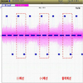
도 5는 일반부하 케이블에서의 노이즈를 측정한 예를 나타내는 도면
도 6은 트위스트(twisted) 케이블의 노이즈를 측정한 예를 나타내는 도면
도 7은 본 발명의 일 실시예에 따른 충·방전기용 대전류 저노이즈 케이블의 노이즈를 측정한 예를 나타내는 도면1 illustrates reduction of inductive coupling due to electromotive force cancellation in twisted pair cable
2 is a block diagram showing a system for charging and discharging a secondary battery using a large current low noise cable for charging and discharging according to an embodiment of the present invention.
FIG. 3A is a cross-sectional view of a high current low noise cable for charger and discharger of FIG. 1. FIG.
FIG. 3B is a longitudinal sectional view of the high current low noise cable for charger and discharger of FIG. 1; FIG.
3C is a diagram illustrating another embodiment of a cross-sectional view of the high current low noise cable for charger and discharger of FIG. 1.
3D is a view showing another embodiment of the longitudinal cross-sectional view of the high current and low noise cable for charger and discharger of FIG.
4 is a view showing an example of a high-current low-noise cable for charge and discharge implemented in real
5 is a diagram illustrating an example of measuring noise in a general load cable.
6 shows an example in which noise of a twisted cable is measured.
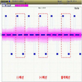
7 is a diagram illustrating an example of measuring noise of a large current low noise cable for a charger / discharger according to an embodiment of the present invention.
이하, 본 발명에 따른 충·방전기용 대전류 저노이즈 케이블을 실시하기 위한 구체적인 내용을 설명하면 다음과 같다.
Hereinafter, a detailed description for carrying out the high current low noise cable for charging and discharging according to the present invention will be described.
도 2는 본 발명의 일 실시예에 따른 충·방전기용 대전류 저노이즈 케이블을 이용하여 2차 전지를 충방전하는 시스템을 나타내는 구성도이다.2 is a block diagram showing a system for charging and discharging a secondary battery using a large current low noise cable for charging and discharging according to an embodiment of the present invention.
도 2를 참조하면, 케이블(230)은 전원(210)과 충·방전기(220)를 연결하며, 충·방전기(220)는 2차전지(240)를 충방전할 수 있다.Referring to FIG. 2, the
전원(210)은 충·방전기(220)를 통해 2차전지(240)에 전력을 공급하여 2차전지(240)를 충방전한다. 일 실시예에서, 전원(210)은 직류(DC) 전원에 해당할 수 있다. 구현 예에 따라 전원(210)은 하나의 전원에서 다수의 충·방전기에 각각 직류 전압을 공급하는 형태일 수도 있고, 하나의 전원에 하나의 충·방전기가 매칭되어 각 전원이 매칭되는 충·방전기에 직류 전압을 공급하는 형태일 수도 있다.The
충·방전기(220)는 전원(210)으로부터 공급받은 전력을 이용하여 2차전지(240)의 충방전을 제어한다. 예를 들어, 충·방전기(220)는 2차전지(240)의 현재 충방전 상태를 모니터링하고, 관리자에 의해 기 설정된 조건에 따라 2차전지(240)를 충방전한다. 구현 예에 따라 충·방전기(220)는 하나의 충·방전기(220)가 다수의 2차전지(240)를 충방전하는 형태일 수도 있고, 하나의 2차전지(240)에 하나의 충·방전기(220)가 매칭되어 각각의 2차전지(240)를 충방전하는 형태일 수도 있다. 도 2에서는 충방전대상을 2차전지를 예시로 하였으나, EDLC(Electrical Double Layer Capacitor)도 충·방전기(220)에 연결되어 충방전될 수 있다.The charger /
케이블(230)은 전원(210)과 충·방전기(220)를 연결하여 충·방전기(220)에 전력을 공급한다.The
고용량의 2차전지 또는 EDLC를 충방전하는 경우, 전원(210), 충·방전기(220) 및 케이블(230)도 고용량 충방전을 지원할 수 있어야 한다. 이하에서는, 고용량 충방전이 가능하고 케이블에서 발생하는 노이즈를 줄일 수 있는 충·방전기용 대전류 저노이즈 케이블(230)에 대해 설명하기로 한다.
When charging and discharging a high capacity secondary battery or EDLC, the
도 3a는 도 1의 충·방전기용 대전류 저노이즈 케이블의 횡단면도를 나타내는 도면이고, 도 3b는 도 1의 충·방전기용 대전류 저노이즈 케이블의 종단면도를 나타내는 도면이다.3A is a diagram showing a cross-sectional view of the high current low noise cable for charger and discharger of FIG. 1, and FIG. 3B is a diagram showing a longitudinal cross-sectional view of the high current low noise cable for charger and discharger of FIG. 1.
도 3a와 도 3b를 참조하면, 충·방전기용 대전류 저노이즈 케이블(230)은 양극 선(310), 제1 절연부재(320), 음극 선(330) 및 제2 절연부재(340)를 포함한다.3A and 3B, the high current
양극 선(310)과 음극 선(330)은 각각 전원(210)과 충·방전기(220)의 양극 단자와 음극단자에 연결된다. 일 실시예에서, 양극 선(310)과 음극 선(330)은 각각 복수의 낱개 도선으로 이루어진 선일 수 있으며, 각 낱개 도선은 구리 선 또는 알루미늄 선(HAL, ACSR)을 포함할 수 있다. 일 실시예에서, 양극선(310)과 음극 선(330)은 임피던스(impedance)가 동일하도록 구성될 수 있다.The
도 3a와 도 3b에서 양극 선(310)은 원형으로 구성되고 음극 선(330)은 링(ring) 형으로 구성된 것으로 도시되었으나, 구현 예에 따라 다른 형상으로 구현될 수도 있다.In FIGS. 3A and 3B, the
제1 절연부재(320)는 양극 선(310)의 외측을 둘러싸고, 양극 선(310)과 음극선(330) 사이를 절연시킨다. 일 실시예에서, 제1 절연부재(320)는 FR-PVC(난연 폴리염화비닐) 소재로 이루어질 수 있다.The first insulating
음극 선(330)은 제1 절연부재(320)의 외측을 둘러싸고, 제2 절연부재(340)는 음극 선(330)의 외측을 둘러싸도록 구성될 수 있다. 일 실시예에서, 제2 절연부재(340)는 FR-PVC(난연 폴리염화비닐) 소재로 이루어질 수 있다. 다른 실시예에서, 제2 절연부재(340)는 외부의 오염과 물리적 충격에 견딜 수 있는 PU(폴리우레탄) 소재로 이루어질 수도 있다.The
상기와 같이 구성된 충·방전기용 대전류 저노이즈 케이블(230)은 기존의 두 개의 선을 트위스트한 고용량 케이블 형태가 아니라 하나의 선이 다른 선을 감싸는 형태로 구성되어 기존의 고용량 케이블보다 부피가 감소하면서 일정하게 형태를 유지 할 수 있다. 또한, 충·방전기용 대전류 저노이즈 케이블(230)은 두 개의 선을 꼬아(트위스트하여) 전자기를 서로 상쇄하는 것보다 자기장이 덜 생기게 하여 유도성 결합에 의한 전기 노이즈를 감소시키는 것을 기대 할 수 있다.The high-current low-
충·방전기용 대전류 저노이즈 케이블(230)은 2차전지 또는 EDLC의 충방전상태를 체크하는 양극 센싱(sensing) 도선(350) 및 음극 센싱 도선(360)을 더 포함할 수 있다.The high current
일 실시예에서, 양극 센싱 도선(350)과 음극 센싱 도선(360)은 음극 선(330)과 제2 절연부재(340) 사이에 위치할 수 있다. 다른 실시예에서, 양극 센싱 도선(350)과 음극 센싱 도선(360)은 제2 절연부재(340) 사이에 위치할 수도 있다.In one embodiment, the
양극 센싱도선(350)과 음극 센싱도선(360)은 꼬아져서(twisted) 케이블(230)의 길이 방향으로 연장될 수 있다. 일 실시예에서, 양극 센싱도선(350)과 음극 센싱도선(360)은 2차전지 또는 EDLC와 테스트 장치(미도시)를 연결하여 2차전지 또는 EDLC의 충방전상태를 체크하도록 할 수 있다.The
일 실시예에서, 케이블(230)은 꼬아진(twisted) 양극 센싱도선(350)과 음극 센싱도선(360)에서 발생하는 자기장이 영향을 미치지 않도록 자기장 차폐층(미도시)으로 둘러싸이고, 음극 선(330)과 제2 절연부재(340) 사이에 위치할 수 있다. 다른 실시예에서, 양극 센싱도선(350)은 양극선(310)과 제1 차폐부재(320) 사이에 위치하고, 음극 센싱도선(360)은 음극 선(330)과 제2 절연부재(340) 사이에 위치하도록 구성될 수도 있다.In one embodiment, the
양극 선(310), 제1 절연부재(320), 음극 선(330) 및 제2 절연부재(340)의 두께는 충·방전기용 대전류 저노이즈 케이블(230)의 용량에 따라 달라질 수 있다. 예를 들어, 제1 절연부재(320)와 제2 절연부재(340)는 일정한 전계강도를 갖도록 실험을 통해 미리 결정된 범위의 두께를 갖도록 구현될 수 있다. The thickness of the
상기에서 예로 든 양극 선(310), 제1 절연부재(320), 음극 선(330) 및 제2 절연부재(340)의 두께는 일 실시예이며, 구현 예에 따라 두께는 달라질 수 있다.The thickness of the
도 3c는 도 1의 충·방전기용 대전류 저노이즈 케이블의 횡단면도의 다른 실시예를 나타내는 도면이고, 도 3d는 도 1의 충·방전기용 대전류 저노이즈 케이블의 종단면도의 다른 실시예를 나타내는 도면이다.3C is a diagram illustrating another embodiment of a cross-sectional view of the high current low noise cable for charger and discharger of FIG. 1, and FIG. 3D is a diagram illustrating another embodiment of a longitudinal cross-sectional view of the high current low noise cable for charger and discharger of FIG. 1.
일 실시예에서, 양극 센싱 도선(350)과 음극 센싱 도선(360)은 제1 절연부재(320)와 음극 선(330) 사이에 위치할 수 있다. 예를 들어, 양극 센싱 도선(350)과 음극 센싱 도선(360)은 도 3c 및 도 3d와 같이 제1 절연부재(320)의 외경에 맞닿아 제1 절연부재(320)와 음극 선(330) 사이에 위치할 수 있다. 다른 실시예에서, 양극 센싱 도선(350)과 음극 센싱 도선(360)은 음극 선(330) 사이에 사이에 위치할 수도 있다.
In one embodiment, the
도 5는 일반부하 케이블에서의 노이즈를 측정한 예를 나타내는 도면이다. 또한, 도 6은 트위스트(twisted) 케이블의 노이즈를 측정한 예를 나타내는 도면이다.5 is a diagram illustrating an example of measuring noise in a general load cable. 6 is a figure which shows the example which measured the noise of the twisted cable.
도 5를 참조하면, 오실로스코프를 통해 70SQ 규격의 일반부하 케이블의 출력 노이즈를 측정한 도면이고, 도 6은 70SQ 규격의 트위스트(twisted) 케이블의 노이즈를 측정한 도면이다. 각 도면에는 음극(-) 선, 양극(+) 선 및 출력 케이블 전체의 노이즈가 도시되어 있다.
Referring to FIG. 5, an output noise of a 70SQ standard general load cable is measured through an oscilloscope, and FIG. 6 is a diagram of noise of a twisted cable of 70SQ standard. Each figure shows the negative (-) line, the positive (+) line, and the noise of the entire output cable.
도 7은 본 발명의 일 실시예에 따른 충·방전기용 대전류 저노이즈 케이블의 노이즈를 측정한 예를 나타내는 도면이다. 7 is a diagram illustrating an example of measuring noise of a high current low noise cable for a charger and a discharger according to an embodiment of the present invention.
도 7을 참조하면, 도 7은 본 발명의 충·방전기용 대전류 저노이즈 케이블의 의 노이즈를 측정한 도면으로, 음극(-) 선, 양극(+) 선 및 출력 케이블 전체의 노이즈가 도시되어 있다. 도 7의 측정 결과를 보면, 출력 케이블 전체에서의 노이즈가 도 5와 도6의 케이블에 비해 현저히 낮아지는 것을 확인할 수 있다.
Referring to FIG. 7, FIG. 7 is a diagram measuring noise of the high-current low-noise cable for charging and discharging of the present invention. Looking at the measurement results of Figure 7, it can be seen that the noise in the entire output cable is significantly lower than the cables of Figures 5 and 6.
이상 본 발명의 실시예로 설명하였으나 본 발명의 기술적 사상이 상기 실시예로 한정되는 것은 아니며, 본 발명의 기술적 사상을 벗어나지 않는 범주에서 다양한 충·방전기용 대전류 저노이즈 케이블로 구현할 수 있다.
Although the embodiments of the present invention have been described above, the technical idea of the present invention is not limited to the above embodiments, and various high-current low-noise cables for charging and discharging may be implemented without departing from the technical idea of the present invention.
210 : 전원
220 : 충·방전기
230 : 케이블
240 : 2차전지210: power
220: charger / discharger
230: cable
240: secondary battery
Claims (9)
상기 양극 선의 외측을 둘러싸는 제1 절연부재;
상기 제1 절연부재의 외측을 둘러싸는 음극 선; 및
상기 음극 선의 외측을 둘러싸는 제2 절연부재를 포함하는 충·방전기용 대전류 저노이즈 케이블.
Anode line;
A first insulating member surrounding an outer side of the anode line;
A cathode wire surrounding an outer side of the first insulating member; And
A high current low noise cable for charging and discharging, comprising a second insulating member surrounding the outside of the cathode line.
상기 음극 선과 상기 제2 절연부재 사이에 위치하는 양극 센싱(sensing)도선 및 음극 센싱(sensing)도선을 더 포함하는 것을 특징으로 하는 충·방전기용 대전류 저노이즈 케이블.
The method of claim 1,
The charging and discharging large current low-noise cable further comprises a positive electrode sensing (sensing) lead and the negative electrode sensing (sensing) lead located between the cathode line and the second insulating member.
상기 음극 선과 상기 제1 절연부재 사이에 위치하는 양극 센싱(sensing)도선 및 음극 센싱(sensing)도선을 더 포함하는 것을 특징으로 하는 충·방전기용 대전류 저노이즈 케이블.
The method of claim 1,
And a cathode sensing lead and a cathode sensing lead positioned between the cathode wire and the first insulation member.
상기 양극 센싱도선과 음극 센싱도선은 꼬아져서(twisted) 상기 케이블의 길이 방향으로 연장되는 것을 특징으로 하는 충·방전기용 대전류 저노이즈 케이블.
The method according to claim 2 or 3,
The positive and negative sensing wires are twisted and extended in the longitudinal direction of the cable.
상기 케이블은 상기 전원을 2차전지 또는 EDLC(Electrical Double Layer Capacitor)를 충방전하는 충·방전기를 연결하되,
상기 양극 센싱도선과 음극 센싱도선은 상기 2차전지 또는 EDLC와 테스트 장치를 연결하여 상기 2차전지 또는 EDLC의 충방전상태를 체크하는 충·방전기용 대전류 저노이즈 케이블.
The method according to claim 2 or 3,
The cable connects the power source to a charge / discharger for charging and discharging a secondary battery or an electric double layer capacitor (EDLC),
The positive and negative sensing wires are connected to the secondary battery or EDLC and the test device to check the charge and discharge state of the secondary battery or EDLC high current low noise cable for a charge and discharge.
상기 양극 선과 상기 음극 선은 임피던스가 동일한 것을 특징으로 하는 충·방전기용 대전류 저노이즈 케이블.
The method of claim 1,
A high current low noise cable for a charger / discharger, wherein the anode line and the cathode line have the same impedance.
상기 양극 선과 음극 선은 각각 복수의 낱개 도선으로 이루어진 것을 특징으로 하는 충·방전기용 대전류 저노이즈 케이블.
The method of claim 1,
The positive and negative wires are high current low noise cables for charging and discharging, characterized in that each consisting of a plurality of individual wires.
상기 제1 절연부재 및 상기 제2 절연부재는 FR-PVC 소재로 이루어진 것을 특징으로 하는 충·방전기용 대전류 저노이즈 케이블.
The method of claim 1,
The first insulating member and the second insulating member is a high-current low-noise cable for charging and discharging, characterized in that the FR-PVC material.
상기 제1 절연부재는 FR-PVC(난연 폴리염화비닐) 소재로 이루어지고, 상기 제2 절연부재는 PU(폴리우레탄) 소재로 이루어진 것을 특징으로 하는 충·방전기용 대전류 저노이즈 케이블.
The method of claim 1,
The first insulating member is made of FR-PVC (flame-retardant polyvinyl chloride) material, the second insulating member is a high current low noise cable for charging and discharging, characterized in that made of PU (polyurethane) material.
Priority Applications (3)
| Application Number | Priority Date | Filing Date | Title |
|---|---|---|---|
| KR1020180104549A KR20200026517A (en) | 2018-09-03 | 2018-09-03 | Low Noise Cable For Charger and Discharger |
| CN201910806313.9A CN110444334A (en) | 2018-09-03 | 2019-08-29 | A kind of charge-discharge machine high current low noise cable |
| CN201921419053.1U CN210805320U (en) | 2018-09-03 | 2019-08-29 | High-current low-noise cable for charge and discharge motor |
Applications Claiming Priority (1)
| Application Number | Priority Date | Filing Date | Title |
|---|---|---|---|
| KR1020180104549A KR20200026517A (en) | 2018-09-03 | 2018-09-03 | Low Noise Cable For Charger and Discharger |
Publications (1)
| Publication Number | Publication Date |
|---|---|
| KR20200026517A true KR20200026517A (en) | 2020-03-11 |
Family
ID=68438324
Family Applications (1)
| Application Number | Title | Priority Date | Filing Date |
|---|---|---|---|
| KR1020180104549A KR20200026517A (en) | 2018-09-03 | 2018-09-03 | Low Noise Cable For Charger and Discharger |
Country Status (2)
| Country | Link |
|---|---|
| KR (1) | KR20200026517A (en) |
| CN (2) | CN210805320U (en) |
Families Citing this family (1)
| Publication number | Priority date | Publication date | Assignee | Title |
|---|---|---|---|---|
| KR20200026517A (en) * | 2018-09-03 | 2020-03-11 | 주식회사 피앤이솔루션 | Low Noise Cable For Charger and Discharger |
Citations (1)
| Publication number | Priority date | Publication date | Assignee | Title |
|---|---|---|---|---|
| KR20130011547A (en) | 2011-07-22 | 2013-01-30 | 대우조선해양 주식회사 | Noisi shielding cable |
Family Cites Families (9)
| Publication number | Priority date | Publication date | Assignee | Title |
|---|---|---|---|---|
| JP2003068151A (en) * | 2001-08-29 | 2003-03-07 | Toyota Industries Corp | Shield cable |
| CN201130546Y (en) * | 2007-12-17 | 2008-10-08 | 陈鸿华 | Improved structure of DC supply line |
| CN201590470U (en) * | 2009-02-18 | 2010-09-22 | 谭洪奎 | AC power supply type radio-frequency coaxial cable |
| JP6014910B2 (en) * | 2011-01-21 | 2016-10-26 | 矢崎総業株式会社 | High voltage conductive path and wire harness |
| JP5661536B2 (en) * | 2011-03-30 | 2015-01-28 | 富士重工業株式会社 | Electric vehicle |
| JP2014022219A (en) * | 2012-07-19 | 2014-02-03 | Yazaki Corp | Wire harness |
| CN203134401U (en) * | 2012-12-21 | 2013-08-14 | 上海起帆电线电缆有限公司 | Power source line used in strong magnetic field |
| CN105931710A (en) * | 2016-06-22 | 2016-09-07 | 镇江四益电子有限公司 | High-temperature resistant connection cable for electric vehicle drive motor |
| KR20200026517A (en) * | 2018-09-03 | 2020-03-11 | 주식회사 피앤이솔루션 | Low Noise Cable For Charger and Discharger |
-
2018
- 2018-09-03 KR KR1020180104549A patent/KR20200026517A/en not_active Application Discontinuation
-
2019
- 2019-08-29 CN CN201921419053.1U patent/CN210805320U/en active Active
- 2019-08-29 CN CN201910806313.9A patent/CN110444334A/en active Pending
Patent Citations (1)
| Publication number | Priority date | Publication date | Assignee | Title |
|---|---|---|---|---|
| KR20130011547A (en) | 2011-07-22 | 2013-01-30 | 대우조선해양 주식회사 | Noisi shielding cable |
Also Published As
| Publication number | Publication date |
|---|---|
| CN110444334A (en) | 2019-11-12 |
| CN210805320U (en) | 2020-06-19 |
Similar Documents
| Publication | Publication Date | Title |
|---|---|---|
| JP5362116B2 (en) | Method and apparatus for protecting a power system from superparamagnetic pulses | |
| US8487606B2 (en) | Sensor assembly, trip unit including the same, and method of manufacturing a sensor assembly | |
| US9739804B2 (en) | Closure for measuring voltage on power-carrying conductors | |
| CN106324454B (en) | A kind of XLPE cable insulation detection device and its electromagnetism interference method | |
| JP5842021B2 (en) | Fast current shunt | |
| CN210742376U (en) | Sleeve tap current and voltage monitoring device | |
| CN105953911A (en) | Vibration sensor used for monitoring mechanical fault of high-voltage circuit breaker | |
| US20210249156A1 (en) | Capacitive Power Transmission Cable | |
| CN105023644A (en) | Novel tubular bus system | |
| KR20200026517A (en) | Low Noise Cable For Charger and Discharger | |
| US4413304A (en) | Electromagnetic field compensated cable | |
| KR20160102338A (en) | Ionizer | |
| US6717790B1 (en) | Creeping discharge lightning protection device | |
| JP2012059495A (en) | Charging cable for electric vehicle | |
| CN102214812B (en) | Battery pack with static discharge protective function and electronic device | |
| KR20130047864A (en) | Apparatus for generating a high frequency pulse and apparatus for testing a coaxial protector using the same | |
| CN114270649A (en) | Protection of AC equipment | |
| CN219419990U (en) | Power distribution control device | |
| CN220107808U (en) | Power module, power adapter and power | |
| JP6089573B2 (en) | Vacuum capacitor type instrument transformer | |
| KR101184670B1 (en) | Power cable for alternating current | |
| JP2003337144A (en) | Method and apparatus for voltage detection in distribution line | |
| JP3421168B2 (en) | Bushing | |
| KR20140115509A (en) | Premolded joint for DC cable | |
| US20120161906A1 (en) | Resonant Circuit |
Legal Events
| Date | Code | Title | Description |
|---|---|---|---|
| A201 | Request for examination | ||
| E902 | Notification of reason for refusal | ||
| E601 | Decision to refuse application |