KR20200026030A - Heat exchange apparatus - Google Patents
Heat exchange apparatus Download PDFInfo
- Publication number
- KR20200026030A KR20200026030A KR1020190083992A KR20190083992A KR20200026030A KR 20200026030 A KR20200026030 A KR 20200026030A KR 1020190083992 A KR1020190083992 A KR 1020190083992A KR 20190083992 A KR20190083992 A KR 20190083992A KR 20200026030 A KR20200026030 A KR 20200026030A
- Authority
- KR
- South Korea
- Prior art keywords
- heat exchanger
- side wall
- passage
- outer casing
- leaf spring
- Prior art date
Links
- 238000007789 sealing Methods 0.000 claims abstract description 67
- 239000012530 fluid Substances 0.000 claims abstract description 43
- 230000000903 blocking effect Effects 0.000 claims abstract description 4
- 238000003780 insertion Methods 0.000 claims description 21
- 230000037431 insertion Effects 0.000 claims description 20
- 238000000034 method Methods 0.000 claims description 9
- 230000002093 peripheral effect Effects 0.000 claims description 5
- 238000003825 pressing Methods 0.000 claims description 3
- 238000007599 discharging Methods 0.000 claims description 2
- 238000005192 partition Methods 0.000 abstract description 3
- XLYOFNOQVPJJNP-UHFFFAOYSA-N water Substances O XLYOFNOQVPJJNP-UHFFFAOYSA-N 0.000 description 59
- 238000002485 combustion reaction Methods 0.000 description 37
- 239000007789 gas Substances 0.000 description 36
- 238000003466 welding Methods 0.000 description 9
- 239000002184 metal Substances 0.000 description 6
- 238000010079 rubber tapping Methods 0.000 description 5
- 238000005476 soldering Methods 0.000 description 5
- 235000013399 edible fruits Nutrition 0.000 description 4
- 238000010438 heat treatment Methods 0.000 description 4
- 229910000831 Steel Inorganic materials 0.000 description 3
- 239000002737 fuel gas Substances 0.000 description 3
- 238000002156 mixing Methods 0.000 description 3
- 239000010959 steel Substances 0.000 description 3
- 238000005452 bending Methods 0.000 description 2
- 239000003795 chemical substances by application Substances 0.000 description 2
- 238000001816 cooling Methods 0.000 description 2
- 230000003472 neutralizing effect Effects 0.000 description 2
- 239000003507 refrigerant Substances 0.000 description 2
- 238000011144 upstream manufacturing Methods 0.000 description 2
- OKTJSMMVPCPJKN-UHFFFAOYSA-N Carbon Chemical compound [C] OKTJSMMVPCPJKN-UHFFFAOYSA-N 0.000 description 1
- 230000002378 acidificating effect Effects 0.000 description 1
- 229910052799 carbon Inorganic materials 0.000 description 1
- BWRHOYDPVJPXMF-UHFFFAOYSA-N cis-Caran Natural products C1C(C)CCC2C(C)(C)C12 BWRHOYDPVJPXMF-UHFFFAOYSA-N 0.000 description 1
- 238000004891 communication Methods 0.000 description 1
- 239000002826 coolant Substances 0.000 description 1
- 239000000498 cooling water Substances 0.000 description 1
- 238000010586 diagram Methods 0.000 description 1
- 230000000694 effects Effects 0.000 description 1
- 239000013013 elastic material Substances 0.000 description 1
- 238000005304 joining Methods 0.000 description 1
- 238000003475 lamination Methods 0.000 description 1
- 239000007788 liquid Substances 0.000 description 1
- 238000000465 moulding Methods 0.000 description 1
- 230000002265 prevention Effects 0.000 description 1
- 239000003566 sealing material Substances 0.000 description 1
- 125000006850 spacer group Chemical group 0.000 description 1
- 239000000126 substance Substances 0.000 description 1
- 238000009423 ventilation Methods 0.000 description 1
Images


Classifications
-
- F—MECHANICAL ENGINEERING; LIGHTING; HEATING; WEAPONS; BLASTING
- F28—HEAT EXCHANGE IN GENERAL
- F28F—DETAILS OF HEAT-EXCHANGE AND HEAT-TRANSFER APPARATUS, OF GENERAL APPLICATION
- F28F9/00—Casings; Header boxes; Auxiliary supports for elements; Auxiliary members within casings
- F28F9/005—Other auxiliary members within casings, e.g. internal filling means or sealing means
-
- F—MECHANICAL ENGINEERING; LIGHTING; HEATING; WEAPONS; BLASTING
- F28—HEAT EXCHANGE IN GENERAL
- F28D—HEAT-EXCHANGE APPARATUS, NOT PROVIDED FOR IN ANOTHER SUBCLASS, IN WHICH THE HEAT-EXCHANGE MEDIA DO NOT COME INTO DIRECT CONTACT
- F28D21/00—Heat-exchange apparatus not covered by any of the groups F28D1/00 - F28D20/00
- F28D21/0001—Recuperative heat exchangers
- F28D21/0003—Recuperative heat exchangers the heat being recuperated from exhaust gases
- F28D21/0005—Recuperative heat exchangers the heat being recuperated from exhaust gases for domestic or space-heating systems
- F28D21/0007—Water heaters
-
- F—MECHANICAL ENGINEERING; LIGHTING; HEATING; WEAPONS; BLASTING
- F24—HEATING; RANGES; VENTILATING
- F24H—FLUID HEATERS, e.g. WATER OR AIR HEATERS, HAVING HEAT-GENERATING MEANS, e.g. HEAT PUMPS, IN GENERAL
- F24H1/00—Water heaters, e.g. boilers, continuous-flow heaters or water-storage heaters
- F24H1/10—Continuous-flow heaters, i.e. heaters in which heat is generated only while the water is flowing, e.g. with direct contact of the water with the heating medium
- F24H1/107—Continuous-flow heaters, i.e. heaters in which heat is generated only while the water is flowing, e.g. with direct contact of the water with the heating medium using fluid fuel
-
- F—MECHANICAL ENGINEERING; LIGHTING; HEATING; WEAPONS; BLASTING
- F16—ENGINEERING ELEMENTS AND UNITS; GENERAL MEASURES FOR PRODUCING AND MAINTAINING EFFECTIVE FUNCTIONING OF MACHINES OR INSTALLATIONS; THERMAL INSULATION IN GENERAL
- F16F—SPRINGS; SHOCK-ABSORBERS; MEANS FOR DAMPING VIBRATION
- F16F1/00—Springs
- F16F1/02—Springs made of steel or other material having low internal friction; Wound, torsion, leaf, cup, ring or the like springs, the material of the spring not being relevant
- F16F1/18—Leaf springs
- F16F1/182—Leaf springs with inter-engaging portions between leaves or between leaves and mountings, e.g. ridges, notches, ripples
-
- F—MECHANICAL ENGINEERING; LIGHTING; HEATING; WEAPONS; BLASTING
- F16—ENGINEERING ELEMENTS AND UNITS; GENERAL MEASURES FOR PRODUCING AND MAINTAINING EFFECTIVE FUNCTIONING OF MACHINES OR INSTALLATIONS; THERMAL INSULATION IN GENERAL
- F16L—PIPES; JOINTS OR FITTINGS FOR PIPES; SUPPORTS FOR PIPES, CABLES OR PROTECTIVE TUBING; MEANS FOR THERMAL INSULATION IN GENERAL
- F16L19/00—Joints in which sealing surfaces are pressed together by means of a member, e.g. a swivel nut, screwed on or into one of the joint parts
- F16L19/06—Joints in which sealing surfaces are pressed together by means of a member, e.g. a swivel nut, screwed on or into one of the joint parts in which radial clamping is obtained by wedging action on non-deformed pipe ends
- F16L19/07—Joints in which sealing surfaces are pressed together by means of a member, e.g. a swivel nut, screwed on or into one of the joint parts in which radial clamping is obtained by wedging action on non-deformed pipe ends adapted for use in socket or sleeve connections
-
- F—MECHANICAL ENGINEERING; LIGHTING; HEATING; WEAPONS; BLASTING
- F16—ENGINEERING ELEMENTS AND UNITS; GENERAL MEASURES FOR PRODUCING AND MAINTAINING EFFECTIVE FUNCTIONING OF MACHINES OR INSTALLATIONS; THERMAL INSULATION IN GENERAL
- F16L—PIPES; JOINTS OR FITTINGS FOR PIPES; SUPPORTS FOR PIPES, CABLES OR PROTECTIVE TUBING; MEANS FOR THERMAL INSULATION IN GENERAL
- F16L21/00—Joints with sleeve or socket
- F16L21/02—Joints with sleeve or socket with elastic sealing rings between pipe and sleeve or between pipe and socket, e.g. with rolling or other prefabricated profiled rings
- F16L21/035—Joints with sleeve or socket with elastic sealing rings between pipe and sleeve or between pipe and socket, e.g. with rolling or other prefabricated profiled rings placed around the spigot end before connection
-
- F—MECHANICAL ENGINEERING; LIGHTING; HEATING; WEAPONS; BLASTING
- F16—ENGINEERING ELEMENTS AND UNITS; GENERAL MEASURES FOR PRODUCING AND MAINTAINING EFFECTIVE FUNCTIONING OF MACHINES OR INSTALLATIONS; THERMAL INSULATION IN GENERAL
- F16L—PIPES; JOINTS OR FITTINGS FOR PIPES; SUPPORTS FOR PIPES, CABLES OR PROTECTIVE TUBING; MEANS FOR THERMAL INSULATION IN GENERAL
- F16L41/00—Branching pipes; Joining pipes to walls
- F16L41/08—Joining pipes to walls or pipes, the joined pipe axis being perpendicular to the plane of the wall or to the axis of another pipe
- F16L41/088—Joining pipes to walls or pipes, the joined pipe axis being perpendicular to the plane of the wall or to the axis of another pipe fixed using an elastic grommet between the extremity of the tube and the wall
-
- F—MECHANICAL ENGINEERING; LIGHTING; HEATING; WEAPONS; BLASTING
- F16—ENGINEERING ELEMENTS AND UNITS; GENERAL MEASURES FOR PRODUCING AND MAINTAINING EFFECTIVE FUNCTIONING OF MACHINES OR INSTALLATIONS; THERMAL INSULATION IN GENERAL
- F16L—PIPES; JOINTS OR FITTINGS FOR PIPES; SUPPORTS FOR PIPES, CABLES OR PROTECTIVE TUBING; MEANS FOR THERMAL INSULATION IN GENERAL
- F16L5/00—Devices for use where pipes, cables or protective tubing pass through walls or partitions
- F16L5/02—Sealing
- F16L5/10—Sealing by using sealing rings or sleeves only
-
- F—MECHANICAL ENGINEERING; LIGHTING; HEATING; WEAPONS; BLASTING
- F23—COMBUSTION APPARATUS; COMBUSTION PROCESSES
- F23D—BURNERS
- F23D14/00—Burners for combustion of a gas, e.g. of a gas stored under pressure as a liquid
- F23D14/02—Premix gas burners, i.e. in which gaseous fuel is mixed with combustion air upstream of the combustion zone
-
- F—MECHANICAL ENGINEERING; LIGHTING; HEATING; WEAPONS; BLASTING
- F23—COMBUSTION APPARATUS; COMBUSTION PROCESSES
- F23D—BURNERS
- F23D14/00—Burners for combustion of a gas, e.g. of a gas stored under pressure as a liquid
- F23D14/46—Details, e.g. noise reduction means
-
- F—MECHANICAL ENGINEERING; LIGHTING; HEATING; WEAPONS; BLASTING
- F24—HEATING; RANGES; VENTILATING
- F24H—FLUID HEATERS, e.g. WATER OR AIR HEATERS, HAVING HEAT-GENERATING MEANS, e.g. HEAT PUMPS, IN GENERAL
- F24H1/00—Water heaters, e.g. boilers, continuous-flow heaters or water-storage heaters
- F24H1/10—Continuous-flow heaters, i.e. heaters in which heat is generated only while the water is flowing, e.g. with direct contact of the water with the heating medium
- F24H1/12—Continuous-flow heaters, i.e. heaters in which heat is generated only while the water is flowing, e.g. with direct contact of the water with the heating medium in which the water is kept separate from the heating medium
- F24H1/14—Continuous-flow heaters, i.e. heaters in which heat is generated only while the water is flowing, e.g. with direct contact of the water with the heating medium in which the water is kept separate from the heating medium by tubes, e.g. bent in serpentine form
- F24H1/145—Continuous-flow heaters, i.e. heaters in which heat is generated only while the water is flowing, e.g. with direct contact of the water with the heating medium in which the water is kept separate from the heating medium by tubes, e.g. bent in serpentine form using fluid fuel
-
- F—MECHANICAL ENGINEERING; LIGHTING; HEATING; WEAPONS; BLASTING
- F24—HEATING; RANGES; VENTILATING
- F24H—FLUID HEATERS, e.g. WATER OR AIR HEATERS, HAVING HEAT-GENERATING MEANS, e.g. HEAT PUMPS, IN GENERAL
- F24H1/00—Water heaters, e.g. boilers, continuous-flow heaters or water-storage heaters
- F24H1/22—Water heaters other than continuous-flow or water-storage heaters, e.g. water heaters for central heating
- F24H1/40—Water heaters other than continuous-flow or water-storage heaters, e.g. water heaters for central heating with water tube or tubes
-
- F—MECHANICAL ENGINEERING; LIGHTING; HEATING; WEAPONS; BLASTING
- F24—HEATING; RANGES; VENTILATING
- F24H—FLUID HEATERS, e.g. WATER OR AIR HEATERS, HAVING HEAT-GENERATING MEANS, e.g. HEAT PUMPS, IN GENERAL
- F24H8/00—Fluid heaters characterised by means for extracting latent heat from flue gases by means of condensation
- F24H8/006—Means for removing condensate from the heater
-
- F—MECHANICAL ENGINEERING; LIGHTING; HEATING; WEAPONS; BLASTING
- F24—HEATING; RANGES; VENTILATING
- F24H—FLUID HEATERS, e.g. WATER OR AIR HEATERS, HAVING HEAT-GENERATING MEANS, e.g. HEAT PUMPS, IN GENERAL
- F24H9/00—Details
- F24H9/0005—Details for water heaters
-
- F—MECHANICAL ENGINEERING; LIGHTING; HEATING; WEAPONS; BLASTING
- F24—HEATING; RANGES; VENTILATING
- F24H—FLUID HEATERS, e.g. WATER OR AIR HEATERS, HAVING HEAT-GENERATING MEANS, e.g. HEAT PUMPS, IN GENERAL
- F24H9/00—Details
- F24H9/12—Arrangements for connecting heaters to circulation pipes
- F24H9/13—Arrangements for connecting heaters to circulation pipes for water heaters
- F24H9/139—Continuous flow heaters
-
- F—MECHANICAL ENGINEERING; LIGHTING; HEATING; WEAPONS; BLASTING
- F24—HEATING; RANGES; VENTILATING
- F24H—FLUID HEATERS, e.g. WATER OR AIR HEATERS, HAVING HEAT-GENERATING MEANS, e.g. HEAT PUMPS, IN GENERAL
- F24H9/00—Details
- F24H9/14—Arrangements for connecting different sections, e.g. in water heaters
- F24H9/146—Connecting elements of a heat exchanger
-
- F—MECHANICAL ENGINEERING; LIGHTING; HEATING; WEAPONS; BLASTING
- F24—HEATING; RANGES; VENTILATING
- F24H—FLUID HEATERS, e.g. WATER OR AIR HEATERS, HAVING HEAT-GENERATING MEANS, e.g. HEAT PUMPS, IN GENERAL
- F24H9/00—Details
- F24H9/18—Arrangement or mounting of grates or heating means
- F24H9/1809—Arrangement or mounting of grates or heating means for water heaters
- F24H9/1832—Arrangement or mounting of combustion heating means, e.g. grates or burners
- F24H9/1836—Arrangement or mounting of combustion heating means, e.g. grates or burners using fluid fuel
-
- F—MECHANICAL ENGINEERING; LIGHTING; HEATING; WEAPONS; BLASTING
- F24—HEATING; RANGES; VENTILATING
- F24H—FLUID HEATERS, e.g. WATER OR AIR HEATERS, HAVING HEAT-GENERATING MEANS, e.g. HEAT PUMPS, IN GENERAL
- F24H9/00—Details
- F24H9/20—Arrangement or mounting of control or safety devices
- F24H9/2007—Arrangement or mounting of control or safety devices for water heaters
- F24H9/2035—Arrangement or mounting of control or safety devices for water heaters using fluid fuel
-
- F—MECHANICAL ENGINEERING; LIGHTING; HEATING; WEAPONS; BLASTING
- F28—HEAT EXCHANGE IN GENERAL
- F28D—HEAT-EXCHANGE APPARATUS, NOT PROVIDED FOR IN ANOTHER SUBCLASS, IN WHICH THE HEAT-EXCHANGE MEDIA DO NOT COME INTO DIRECT CONTACT
- F28D9/00—Heat-exchange apparatus having stationary plate-like or laminated conduit assemblies for both heat-exchange media, the media being in contact with different sides of a conduit wall
- F28D9/0031—Heat-exchange apparatus having stationary plate-like or laminated conduit assemblies for both heat-exchange media, the media being in contact with different sides of a conduit wall the conduits for one heat-exchange medium being formed by paired plates touching each other
- F28D9/0043—Heat-exchange apparatus having stationary plate-like or laminated conduit assemblies for both heat-exchange media, the media being in contact with different sides of a conduit wall the conduits for one heat-exchange medium being formed by paired plates touching each other the plates having openings therein for circulation of at least one heat-exchange medium from one conduit to another
-
- F—MECHANICAL ENGINEERING; LIGHTING; HEATING; WEAPONS; BLASTING
- F28—HEAT EXCHANGE IN GENERAL
- F28F—DETAILS OF HEAT-EXCHANGE AND HEAT-TRANSFER APPARATUS, OF GENERAL APPLICATION
- F28F11/00—Arrangements for sealing leaky tubes and conduits
-
- F—MECHANICAL ENGINEERING; LIGHTING; HEATING; WEAPONS; BLASTING
- F28—HEAT EXCHANGE IN GENERAL
- F28F—DETAILS OF HEAT-EXCHANGE AND HEAT-TRANSFER APPARATUS, OF GENERAL APPLICATION
- F28F9/00—Casings; Header boxes; Auxiliary supports for elements; Auxiliary members within casings
- F28F9/001—Casings in the form of plate-like arrangements; Frames enclosing a heat exchange core
- F28F9/002—Casings in the form of plate-like arrangements; Frames enclosing a heat exchange core with fastening means for other structures
-
- F—MECHANICAL ENGINEERING; LIGHTING; HEATING; WEAPONS; BLASTING
- F28—HEAT EXCHANGE IN GENERAL
- F28F—DETAILS OF HEAT-EXCHANGE AND HEAT-TRANSFER APPARATUS, OF GENERAL APPLICATION
- F28F9/00—Casings; Header boxes; Auxiliary supports for elements; Auxiliary members within casings
- F28F9/02—Header boxes; End plates
- F28F9/0219—Arrangements for sealing end plates into casing or header box; Header box sub-elements
-
- F—MECHANICAL ENGINEERING; LIGHTING; HEATING; WEAPONS; BLASTING
- F02—COMBUSTION ENGINES; HOT-GAS OR COMBUSTION-PRODUCT ENGINE PLANTS
- F02M—SUPPLYING COMBUSTION ENGINES IN GENERAL WITH COMBUSTIBLE MIXTURES OR CONSTITUENTS THEREOF
- F02M26/00—Engine-pertinent apparatus for adding exhaust gases to combustion-air, main fuel or fuel-air mixture, e.g. by exhaust gas recirculation [EGR] systems
- F02M26/02—EGR systems specially adapted for supercharged engines
- F02M26/04—EGR systems specially adapted for supercharged engines with a single turbocharger
- F02M26/06—Low pressure loops, i.e. wherein recirculated exhaust gas is taken out from the exhaust downstream of the turbocharger turbine and reintroduced into the intake system upstream of the compressor
-
- F—MECHANICAL ENGINEERING; LIGHTING; HEATING; WEAPONS; BLASTING
- F24—HEATING; RANGES; VENTILATING
- F24H—FLUID HEATERS, e.g. WATER OR AIR HEATERS, HAVING HEAT-GENERATING MEANS, e.g. HEAT PUMPS, IN GENERAL
- F24H15/00—Control of fluid heaters
- F24H15/30—Control of fluid heaters characterised by control outputs; characterised by the components to be controlled
- F24H15/305—Control of valves
- F24H15/315—Control of valves of mixing valves
-
- F—MECHANICAL ENGINEERING; LIGHTING; HEATING; WEAPONS; BLASTING
- F24—HEATING; RANGES; VENTILATING
- F24H—FLUID HEATERS, e.g. WATER OR AIR HEATERS, HAVING HEAT-GENERATING MEANS, e.g. HEAT PUMPS, IN GENERAL
- F24H15/00—Control of fluid heaters
- F24H15/30—Control of fluid heaters characterised by control outputs; characterised by the components to be controlled
- F24H15/345—Control of fans, e.g. on-off control
- F24H15/35—Control of the speed of fans
-
- F—MECHANICAL ENGINEERING; LIGHTING; HEATING; WEAPONS; BLASTING
- F24—HEATING; RANGES; VENTILATING
- F24H—FLUID HEATERS, e.g. WATER OR AIR HEATERS, HAVING HEAT-GENERATING MEANS, e.g. HEAT PUMPS, IN GENERAL
- F24H15/00—Control of fluid heaters
- F24H15/30—Control of fluid heaters characterised by control outputs; characterised by the components to be controlled
- F24H15/355—Control of heat-generating means in heaters
- F24H15/36—Control of heat-generating means in heaters of burners
-
- F—MECHANICAL ENGINEERING; LIGHTING; HEATING; WEAPONS; BLASTING
- F28—HEAT EXCHANGE IN GENERAL
- F28D—HEAT-EXCHANGE APPARATUS, NOT PROVIDED FOR IN ANOTHER SUBCLASS, IN WHICH THE HEAT-EXCHANGE MEDIA DO NOT COME INTO DIRECT CONTACT
- F28D21/00—Heat-exchange apparatus not covered by any of the groups F28D1/00 - F28D20/00
- F28D2021/0019—Other heat exchangers for particular applications; Heat exchange systems not otherwise provided for
- F28D2021/008—Other heat exchangers for particular applications; Heat exchange systems not otherwise provided for for vehicles
- F28D2021/0082—Charged air coolers
-
- F—MECHANICAL ENGINEERING; LIGHTING; HEATING; WEAPONS; BLASTING
- F28—HEAT EXCHANGE IN GENERAL
- F28F—DETAILS OF HEAT-EXCHANGE AND HEAT-TRANSFER APPARATUS, OF GENERAL APPLICATION
- F28F2225/00—Reinforcing means
- F28F2225/02—Reinforcing means for casings
-
- F—MECHANICAL ENGINEERING; LIGHTING; HEATING; WEAPONS; BLASTING
- F28—HEAT EXCHANGE IN GENERAL
- F28F—DETAILS OF HEAT-EXCHANGE AND HEAT-TRANSFER APPARATUS, OF GENERAL APPLICATION
- F28F2265/00—Safety or protection arrangements; Arrangements for preventing malfunction
- F28F2265/16—Safety or protection arrangements; Arrangements for preventing malfunction for preventing leakage
-
- F—MECHANICAL ENGINEERING; LIGHTING; HEATING; WEAPONS; BLASTING
- F28—HEAT EXCHANGE IN GENERAL
- F28F—DETAILS OF HEAT-EXCHANGE AND HEAT-TRANSFER APPARATUS, OF GENERAL APPLICATION
- F28F2265/00—Safety or protection arrangements; Arrangements for preventing malfunction
- F28F2265/26—Safety or protection arrangements; Arrangements for preventing malfunction for allowing differential expansion between elements
-
- F—MECHANICAL ENGINEERING; LIGHTING; HEATING; WEAPONS; BLASTING
- F28—HEAT EXCHANGE IN GENERAL
- F28F—DETAILS OF HEAT-EXCHANGE AND HEAT-TRANSFER APPARATUS, OF GENERAL APPLICATION
- F28F9/00—Casings; Header boxes; Auxiliary supports for elements; Auxiliary members within casings
- F28F9/007—Auxiliary supports for elements
- F28F9/0075—Supports for plates or plate assemblies
-
- F—MECHANICAL ENGINEERING; LIGHTING; HEATING; WEAPONS; BLASTING
- F28—HEAT EXCHANGE IN GENERAL
- F28F—DETAILS OF HEAT-EXCHANGE AND HEAT-TRANSFER APPARATUS, OF GENERAL APPLICATION
- F28F9/00—Casings; Header boxes; Auxiliary supports for elements; Auxiliary members within casings
- F28F9/02—Header boxes; End plates
- F28F9/0219—Arrangements for sealing end plates into casing or header box; Header box sub-elements
- F28F9/0224—Header boxes formed by sealing end plates into covers
- F28F9/0226—Header boxes formed by sealing end plates into covers with resilient gaskets
-
- Y—GENERAL TAGGING OF NEW TECHNOLOGICAL DEVELOPMENTS; GENERAL TAGGING OF CROSS-SECTIONAL TECHNOLOGIES SPANNING OVER SEVERAL SECTIONS OF THE IPC; TECHNICAL SUBJECTS COVERED BY FORMER USPC CROSS-REFERENCE ART COLLECTIONS [XRACs] AND DIGESTS
- Y02—TECHNOLOGIES OR APPLICATIONS FOR MITIGATION OR ADAPTATION AGAINST CLIMATE CHANGE
- Y02B—CLIMATE CHANGE MITIGATION TECHNOLOGIES RELATED TO BUILDINGS, e.g. HOUSING, HOUSE APPLIANCES OR RELATED END-USER APPLICATIONS
- Y02B30/00—Energy efficient heating, ventilation or air conditioning [HVAC]
Landscapes
- Engineering & Computer Science (AREA)
- General Engineering & Computer Science (AREA)
- Mechanical Engineering (AREA)
- Physics & Mathematics (AREA)
- Thermal Sciences (AREA)
- Chemical & Material Sciences (AREA)
- Combustion & Propulsion (AREA)
- Heat-Exchange Devices With Radiators And Conduit Assemblies (AREA)
- Instantaneous Water Boilers, Portable Hot-Water Supply Apparatuses, And Control Of Portable Hot-Water Supply Apparatuses (AREA)
- Details Of Fluid Heaters (AREA)
Abstract
Description
본 발명은 열교환장치에 관한 것이다.The present invention relates to a heat exchanger.
특허문헌 1에 종래의 열교환장치가 개시되어 있다. 이 열교환장치는 외측 케이싱, 열교환체, 공급관, 배출관 및 복수의 관통구멍을 구비하고 있다.
외측 케이싱은 측벽을 포함하는 통형상의 둘레벽에 의해서 제 1 유체가 유통하는 제 1 통로를 구획하고 있다. 열교환체는 외측 케이싱의 제 1 통로 내에 수용되어 있다. 열교환체의 내부에는 제 2 유체가 유통하는 제 2 통로가 형성되어 있다. 구체적으로는, 제 1 유체는 연소배기가스이고, 제 2 유체는 물이다.The outer casing defines a first passage through which the first fluid flows by a cylindrical peripheral wall including side walls. The heat exchanger is accommodated in the first passage of the outer casing. Inside the heat exchanger, a second passage through which the second fluid flows is formed. Specifically, the first fluid is combustion exhaust gas, and the second fluid is water.
공급관 및 배출관은 각각 열교환체에서 측벽으로 향해서 돌출되어 있다. 복수의 관통구멍은 측벽에 관통되도록 형성되어 있다. 각 관통구멍은 공급관 및 배출관을 외측 케이싱의 외부로 돌출시킨다.The supply pipe and the discharge pipe respectively protrude from the heat exchanger toward the side wall. The plurality of through holes are formed to penetrate the side walls. Each through hole projects the supply pipe and the discharge pipe out of the outer casing.
이 열교환장치에서는 공급관에 의해서 열교환체의 제 2 통로에 제 2 유체가 공급된다. 또, 열교환체에 의해서 제 1 통로를 유통하는 제 1 유체와 제 2 통로를 유통하는 제 2 유체의 사이에서 열교환이 실행된다. 그리고, 배출관에 의해서 제 2 통로에서 제 2 유체가 배출된다.In this heat exchanger, the second fluid is supplied to the second passage of the heat exchanger by the supply pipe. Moreover, heat exchange is performed between the 1st fluid which distribute | circulates a 1st passage and the 2nd fluid which distribute | circulate a 2nd passage by a heat exchanger. Then, the second fluid is discharged from the second passage by the discharge pipe.
그런데, 상기한 바와 같이 구성된 열교환장치에서는, 제 1 통로에서 각 관통구멍을 경유하여 외측 케이싱의 외부에 이르는 누출경로를 차단할 필요가 있다. 그러므로, 예를 들면, 외측 케이싱의 둘레벽을 용접 등에 의해서 통형상으로 형성하기 전에, 측벽에 있어서의 각 관통구멍의 둘레 가장자리와 열교환체를 납땜하는 구성 등이 채용될 수 있다.By the way, in the heat exchanger comprised as mentioned above, it is necessary to interrupt the leak path | route to the exterior of an outer casing via each through hole in a 1st channel | path. Therefore, for example, before forming the circumferential wall of the outer casing into a tubular shape by welding or the like, a configuration or the like for soldering the circumferential edge of each through hole in the sidewall and the heat exchanger can be adopted.
그러나, 이 경우, 납땜 부분이 용접 등에 의한 측벽의 변형이나 열교환체의 치수 편차 등의 영향을 받기 쉬우므로, 기밀성의 확보가 어렵게 될 우려가 있다. 그 결과, 이 열교환장치에서는 제 1 유체가 제 1 통로에서 각 관통구멍을 경유하여 외측 케이싱의 외부로 누출될 우려가 있다.In this case, however, the soldered part is susceptible to the deformation of the side wall due to welding or the like and the dimensional deviation of the heat exchanger, so that the airtightness may be difficult to secure. As a result, in this heat exchange apparatus, there exists a possibility that a 1st fluid may leak out of an outer casing via each through hole in a 1st channel | path.
본 발명은 상기한 종래의 실정을 감안하여 이루어진 것으로서, 제 1 유체가 제 1 통로에서 각 관통구멍을 경유하여 외측 케이싱의 외부로 누출되는 것을 더 확실하게 억제할 수 있는 열교환장치를 제공하는 것을 해결하고자 하는 과제로 하고 있다.SUMMARY OF THE INVENTION The present invention has been made in view of the above-described conventional situation, and solves the problem of providing a heat exchanger that can more reliably suppress leakage of the first fluid to the outside of the outer casing via each through hole in the first passage. I'm trying to do that.
본 발명의 열교환장치는, 제 1 측벽을 포함하는 통형상의 둘레벽에 의해서 제 1 유체가 유통하는 제 1 통로를 구획하는 외측 케이싱과; 상기 외측 케이싱의 상기 제 1 통로 내에 수용되며, 제 2 유체가 유통하는 제 2 통로가 내부에 형성되며, 상기 제 1 유체와 상기 제 2 유체의 사이에서 열교환시키는 열교환체와; 상기 열교환체에서 상기 제 1 측벽으로 향해서 돌출되며, 상기 제 2 통로에 상기 제 2 유체를 공급하는 공급관과; 상기 열교환체에서 상기 제 1 측벽으로 향해서 돌출되며, 상기 제 2 통로에서 상기 제 2 유체를 배출하는 배출관과; 상기 제 1 측벽에 관통되도록 형성되며, 상기 공급관 및 상기 배출관을 상기 외측 케이싱의 외부로 돌출시키는 복수의 관통구멍과; 상기 제 1 측벽과 상기 열교환체의 사이에 설치되며, 상기 제 1 통로에서 상기 각 관통구멍을 경유하여 상기 외측 케이싱의 외부에 이르는 누출경로를 차단하는 탄성밀봉부재와; 상기 탄성밀봉부재에 대해서 상기 관통구멍의 관통방향과 평행한 제 1 방향의 탄지력을 작용시킴으로써 상기 탄성밀봉부재를 압축 변형시키는 탄지부재;를 구비하고 있는 것을 특징으로 한다.The heat exchanger of the present invention comprises: an outer casing which partitions a first passage through which a first fluid flows by a cylindrical peripheral wall including a first sidewall; A heat exchanger accommodated in the first passage of the outer casing and having a second passage through which a second fluid flows, for exchanging heat between the first fluid and the second fluid; A supply pipe protruding from the heat exchanger toward the first side wall and supplying the second fluid to the second passage; A discharge pipe protruding from the heat exchanger toward the first side wall and discharging the second fluid from the second passage; A plurality of through holes formed through the first side wall and protruding the supply pipe and the discharge pipe to the outside of the outer casing; An elastic sealing member disposed between the first side wall and the heat exchanger and blocking a leakage path from the first passage to the outside of the outer casing via the through holes; And a holding member for compressing and deforming the elastic sealing member by applying a holding force in a first direction parallel to the through direction of the through hole to the elastic sealing member.
본 발명의 열교환장치에서는, 제 1 측벽과 열교환체의 사이에 설치된 탄성밀봉부재에 대해서, 탄지부재가 관통구멍의 관통방향과 평행한 제 1 방향의 탄지력을 작용시킴으로써, 탄성밀봉부재를 압축 변형시킨다. 이것에 의해서, 탄성밀봉부재는 용접 등에 의한 측벽의 변형이나 열교환체의 치수 편차 등의 영향을 받기 어려우므로, 제 1 통로에서 각 관통구멍을 경유하여 외측 케이싱의 외부에 이르는 누출경로를 확실히 차단할 수 있다.In the heat exchange apparatus of the present invention, the elastic sealing member compresses and deforms the elastic sealing member by applying a force of force in the first direction parallel to the through direction of the through hole to the elastic sealing member provided between the first side wall and the heat exchanger. Let's do it. As a result, since the elastic sealing member is less likely to be affected by deformation of the side wall due to welding or the like and dimensional deviation of the heat exchanger, the leak path from the first passage to the outside of the outer casing can be reliably blocked. have.
따라서, 본 발명의 열교환장치에서는 제 1 유체가 제 1 통로에서 각 관통구멍을 경유하여 외측 케이싱의 외부로 누출되는 것을 더 확실하게 억제할 수 있다.Therefore, in the heat exchanger of the present invention, it is possible to more reliably suppress the leakage of the first fluid to the outside of the outer casing via each through hole in the first passage.
열교환체는 복수의 플레이트가 제 1 방향을 따라서 적층되어 있는 것이 바람직하다.It is preferable that a plurality of plates are laminated in the heat exchanger along the first direction.
이 경우, 열교환체의 제 1 방향의 치수 편차가 각 플레이트의 적층에 의해서 커지게 되는 경향이 있지만, 탄지부재에 탄지된 탄성밀봉부재는 그 치수 편차의 영향을 받기 어렵기 때문에, 제 1 유체가 제 1 통로에서 각 관통구멍을 경유하여 외측 케이싱의 외부로 누출되는 것을 한층 더 확실하게 억제할 수 있다.In this case, the dimensional deviation in the first direction of the heat exchanger tends to be large due to the lamination of the plates, but since the elastic sealing member held on the support member is hardly affected by the dimensional deviation, the first fluid Leaking to the outside of the outer casing through each through hole in the first passage can be more surely suppressed.
둘레벽은 제 1 방향에 있어서 제 1 측벽과 대향하는 제 2 측벽을 포함하고 있는 것이 바람직하다. 그리고, 탄지부재는 제 2 측벽과 열교환체의 사이에 배치되어 열교환체를 제 1 측벽으로 향해서 압압하는 탄지력을 발휘하는 것이 바람직하다.The circumferential wall preferably includes a second side wall facing the first side wall in the first direction. And, it is preferable that the finger member is disposed between the second side wall and the heat exchanger to exert a force for pressing the heat exchanger toward the first side wall.
이 경우, 탄지부재가 열교환체를 압압하는 탄지력이 탄성밀봉부재에 작용하기 쉬우므로, 탄성밀봉부재를 압축 변형시키기 쉽다. 그러므로, 제 1 유체가 제 1 통로에서 각 관통구멍을 경유하여 외측 케이싱의 외부로 누출되는 것을 한층 더 확실하게 억제할 수 있다.In this case, since the finger force which presses the heat exchange member to the elastic sealing member easily acts on the elastic sealing member, the elastic sealing member is easily compressed and deformed. Therefore, leakage of the first fluid to the outside of the outer casing via each through hole in the first passage can be more surely suppressed.
외측 케이싱은 둘레벽의 일단측이 개방된 삽입구를 가지고 있는 것이 바람직하다. 열교환체, 공급관 및 배출관은 삽입구를 경유하여 외측 케이싱의 제 1 통로내에 수용되는 것이 바람직하다. 그리고, 탄지부재는 삽입구를 경유하여 제 2 측벽과 열교환체의 사이에 삽입되는 것이 바람직하다.The outer casing preferably has an insertion opening in which one end side of the circumferential wall is opened. The heat exchanger, the supply pipe and the discharge pipe are preferably accommodated in the first passage of the outer casing via the insertion port. And, it is preferable that the stop member is inserted between the second side wall and the heat exchanger via the insertion hole.
이 경우, 외측 케이싱의 둘레벽을 용접 등에 의해서 통형상으로 형성한 후에, 열교환체, 공급관 및 배출관을 외측 케이싱의 제 1 통로 내에 수용하고, 탄지부재를 제 2 측벽과 열교환체의 사이에 삽입하는 작업을 용이하게 실시할 수 있다.In this case, after the circumferential wall of the outer casing is formed into a tubular shape by welding or the like, the heat exchanger, the supply pipe, and the discharge pipe are accommodated in the first passage of the outer casing, and the stop member is inserted between the second side wall and the heat exchanger. Work can be performed easily.
탄지부재는 제 2 측벽 및 열교환체의 일방에 맞닿는 판형상부재와, 판형상부재에 고정되며 제 2 측벽 및 열교환체의 타방에 탄성 변형된 상태로 맞닿는 판스프링을 가지고 있는 것이 바람직하다. 그리고, 탄지부재가 삽입구를 경유하여 제 2 측벽과 열교환체의 사이에 삽입되는 방향과 평행한 방향을 제 2 방향이라 하면, 판스프링은 제 2 방향의 중간 영역이 제 2 측벽 및 열교환체의 타방으로 향해서 불룩해지도록 만곡되어 있는 것이 바람직하다.The holding member preferably has a plate-like member which is in contact with one side of the second side wall and the heat exchanger, and a leaf spring which is fixed to the plate-like member and in contact with the second sidewall and the heat exchanger in an elastically deformed state. And, if the direction parallel to the direction in which the finger member is inserted between the second side wall and the heat exchanger via the insertion hole is called the second direction, the leaf spring has a middle region in the second direction, the other side of the second side wall and the heat exchanger. It is preferable that it bends so that it may bulge toward the surface.
이 경우, 판형상부재와 만곡된 판스프링에 의해서 탄지부재를 제 2 측벽과 열교환체의 사이에 슬라이딩시켜서 용이하게 삽입할 수 있다. 그리고, 탄지부재는 열교환체를 제 1 측벽으로 향해서 확실하게 압압할 수 있다.In this case, the holding member can be easily inserted by sliding between the second side wall and the heat exchanger by the plate member and the curved leaf spring. Then, the holding member can reliably press the heat exchanger toward the first side wall.
판형상부재는 제 1 측벽으로 향해서 돌출되어 열교환체에 맞닿는 복수의 돌출부를 가지고 있는 것이 바람직하다. 판스프링은 제 2 측벽에 맞닿는 것이 바람직하다. 그리고, 제 1 방향을 따라서 보았을 때, 각 관통구멍은 각각 대응하는 각 돌출부와 겹쳐져 있는 것이 바람직하다.It is preferable that the plate-shaped member has a plurality of protrusions which protrude toward the first side wall and abut against the heat exchanger. The leaf spring preferably contacts the second side wall. In addition, when viewed along the first direction, it is preferable that each through hole overlaps with each corresponding protrusion.
이 경우, 탄지부재의 탄지력이 열교환체를 압압함으로써 판형상부재의 각 돌출부 및 열교환체를 경유하여 탄성밀봉부재에 작용한다.In this case, the holding force of the finger member acts on the elastic sealing member via each of the protrusions and the heat exchange member of the plate member by pressing the heat exchange member.
판스프링은 제 2 방향에 있어서의 삽입구와는 반대측에 위치하는 단부만이 판형상부재에 고정되어 있는 것이 바람직하다.It is preferable that only the edge part located in the leaf spring opposite to the insertion opening in a 2nd direction is being fixed to the plate-shaped member.
이 경우, 탄지부재를 제 2 측벽과 열교환체의 사이에 삽입하는 초기 단계에 있어서 판스프링의 복원력을 약하게 하기 쉽다. 그 결과, 탄지부재를 제 2 측벽과 열교환체의 사이에 한층 더 용이하게 삽입할 수 있다. 또, 이 경우, 탄지부재가 제 2 측벽과 열교환체의 사이에 삽입된 상태에서, 판스프링이 열교환체의 치수 편차에 매우 적합하게 추종하면서 열교환체를 제 1 측벽으로 향해서 확실하게 압압할 수 있다.In this case, it is easy to weaken the restoring force of the leaf spring in the initial stage of inserting the support member between the second side wall and the heat exchanger. As a result, the holding member can be more easily inserted between the second side wall and the heat exchanger. In this case, in the state where the support member is inserted between the second side wall and the heat exchanger, the plate spring can reliably press the heat exchanger toward the first sidewall while following the dimensional deviation of the heat exchanger very well. .
탄지부재는, 일단측이 제 1 측벽에 걸려 고정되고 타단측이 열교환체에 걸려 고정되어, 열교환체를 제 1 측벽으로 향해서 끌어당기는 탄지력을 발휘하는 것이 바람직하다.It is preferable that the finger member is secured by hooking one end side to the first side wall and fixing the other end side to the heat exchanger to attract the heat exchanger toward the first side wall.
이 경우, 탄지부재의 탄지력이 열교환체를 끌어당김으로써 탄성밀봉부재에 작용한다.In this case, the holding force of the holding member acts on the elastic sealing member by attracting the heat exchanger.
본 발명의 열교환장치에 의하면, 제 1 유체가 제 1 통로에서 각 관통구멍을 경유하여 외측 케이싱의 외부로 누출되는 것을 더 확실하게 억제할 수 있다.According to the heat exchanger of the present invention, it is possible to more reliably suppress the first fluid from leaking to the outside of the outer casing via each through hole in the first passage.
도 1은 실시예 1의 열교환장치가 적용되는 급탕기의 모식도이다.
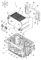
도 2는 실시예 1의 열교환장치의 분해 사시도이다.
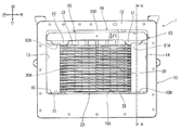
도 3은 실시예 1의 열교환장치의 상면도이다.
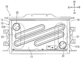
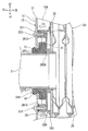
도 4는 도 3의 A-A 단면을 나타내는 단면도이다.
도 5는 도 4의 요부 확대 단면도이다.
도 6은 탄지부재의 사시도이다.
도 7은 외측 케이싱의 각 관통구멍과 판형상부재의 각 돌출부의 상대 위치 관계를 나타내는 측면도이다.
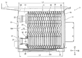
도 8은 도 4와 같은 단면도로서, 열교환체를 외측 케이싱의 제 1 통로 내에 수용하는 순서를 설명하는 도면이다.
도 9는 실시예 2의 열교환장치와 관한 것으로, 도 5와 같은 요부 확대 단면도이다.1 is a schematic diagram of a hot water heater to which the heat exchanger of the first embodiment is applied.
2 is an exploded perspective view of the heat exchanger of the first embodiment.
3 is a top view of the heat exchanger of the first embodiment.
4 is a cross-sectional view illustrating a cross section along AA of FIG. 3.
5 is an enlarged cross-sectional view of the main part of FIG. 4.
6 is a perspective view of the finger member.
Fig. 7 is a side view showing the relative positional relationship between the respective through holes of the outer casing and the protrusions of the plate-like member.
FIG. 8 is a cross-sectional view as shown in FIG. 4, illustrating a procedure for accommodating the heat exchanger in the first passage of the outer casing. FIG.
9 is a view related to the heat exchanger of the second embodiment, and is an enlarged cross-sectional view of the main portion as shown in FIG. 5.
이하, 본 발명을 구체화한 실시예 1, 2에 대해서 도면을 참조하여 설명한다.EMBODIMENT OF THE INVENTION Hereinafter, Example 1, 2 which actualized this invention is demonstrated with reference to drawings.
(실시예 1)(Example 1)
도 1에 나타내는 바와 같이, 실시예 1의 열교환장치(1)는 본 발명의 열교환장치의 구체적 형태의 일례이며, 급탕기(9)에 적용하고 있다. 급탕기(9)는 외장 케이스(90)를 구비하고 있다. 이 외장 케이스(90)는 케이스 본체(90C)와 도시하지 않은 전면 패널에 의해서 구성되어 있다. 케이스 본체(90C)는, 도 1의 지면의 전면측에 개구부가 형성된 직사각형의 상자 형상체이다. 전면 패널은 도 1의 지면의 전면측에 위치하며, 케이스 본체(90C)의 개구부를 덮고 있다.As shown in FIG. 1, the
이하의 설명에서는, 외장 케이스(90)의 전면 패널 측, 즉 도 1의 지면의 전면측을 전방이라 규정하고, 외장 케이스(90)의 전면 패널에 대면하는 상태로 급탕기(9)를 보았을 때에 왼쪽에 오는 측, 즉 도 1의 지면의 좌측을 좌방이라 규정한다. 그리고, 도 2 이후의 각 도면에 나타내는 전후, 좌우 및 상하의 각 방향은 모두 도 1에 대응하여 표시한다.In the following description, the front panel side of the
<급탕기의 구성><Constitution of hot water heater>
도 1에 나타내는 바와 같이, 급탕기(9)는 외장 케이스(90), 버너(8), 제어회로(4), 현열 열교환장치(7), 열교환장치(1), 배기덕트(6) 및 드레인 중화기(5)를 구비하고 있다. 버너(8), 제어회로(4), 현열 열교환장치(7), 열교환장치(1), 배기덕트(6) 및 드레인 중화기(5)는 외장 케이스(90)에 각각 수납되어 있다.As shown in FIG. 1, the hot water heater 9 includes an
외장 케이스(90)의 상벽에는 급기구(91) 및 배기구(92)가 형성되어 있다. 외장 케이스(90)의 외부 공기는 급기구(91)를 경유하여 외장 케이스(90) 내로 취입된다. 배기덕트(6)로 유도된 연소배기가스는 배기구(92)를 경유하여 외장 케이스(90)의 외부로 배출된다.An
외장 케이스(90) 내에는 가스 도입관(94), 입수관(95) 및 출탕관(96)이 배치되어 있으며, 이것들의 하단이 외장 케이스(90)의 하벽에서 돌출되어 있다. 가스 도입관(94)의 하단은 도시하지 않은 가스 공급원에서 연료가스를 공급하기 위한 가스배관(P3)에 접속되어 있다. 입수관(95)의 하단은 도시하지 않은 물 공급원에서 물을 공급하기 위한 급수배관(P1)에 접속되어 있다. 출탕관(96)의 하단은 카란이나 샤워 등의 출탕처(SP)로 탕수를 공급하기 위한 급탕배관(P2)에 접속되어 있다.In the
버너(8)는 버너 보디(81), 연소 플레이트(80), 연소 팬 유닛(85) 및 예혼합기(87)를 가지고 있다.The burner 8 has a
버너 보디(81)는 외장 케이스(90) 내의 상측에 배치되어 있다. 버너 보디(81)는 각(角)통형상의 둘레벽을 가지는 상자형상체이며, 하면측에 개구부가 형성되어 있다. 버너 보디(81)의 우측면의 상부에는 가스 도입구(81H)가 우측 방향으로 돌출되도록 형성되어 있다. 가스 도입구(81H)에는 역류방지밸브(81V)가 설치되어 있다.The
연소 플레이트(80)는 버너 보디(81)의 둘레벽에 둘러싸인 상태로 버너 보디(81)의 하면 개구부에 설치되어 있다. 연소 플레이트(80)는 복수의 불꽃구멍을 가지고 있다.The
연소 팬 유닛(85)은 팬 케이스(85C), 연소 팬(85F) 및 팬 모터(85M)를 가지고 있다.The
팬 케이스(85C)는 버너 보디(81)의 가스 도입구(81H)에 접속되어 있음과 아울러, 가스 흡입구(85H)가 하측 방향으로 돌출되도록 형성되어 있다. 연소 팬(85F)은 팬 케이스(85C)에 수용되어 있다. 연소 팬(85F)은 팬 케이스(85C)의 외부에 고정된 팬 모터(85M)에 의해서 회전 구동된다.The
예혼합기(87)는 연소 팬 유닛(85)의 하측에 배치되며, 가스 흡입구(85H)에 접속되어 있다. 예혼합기(87)는 도시하지 않은 혼합밸브를 가지고 있다. 예혼합기(87)에는 가스 도입관(94)의 상단이 접속되어 있다. 또, 예혼합기(87)에는, 일단이 외장 케이스(90) 내에 개방되어 있는 급기관(93)의 타단이 접속되어 있다.The
제어회로(4)는 급탕기(9)의 기동시부터 정지시까지 작동하는 전기회로이며, 급탕기(9) 전체의 동작을 제어한다. 예를 들면, 제어회로(4)는 버너(8)의 점화나 소화, 연소 팬(85F)을 회전 구동하는 팬 모터(85M)의 회전수의 조정, 예혼합기(87)의 도시하지 않은 혼합밸브의 개방도 조정 등의 제어를 실행한다.The
현열 열교환장치(7)는 부기체(缶器體)(70)를 구비하고 있다. 도 1에 간략하게 나타내는 부기체(70)는 각통형상의 둘레벽을 가지며, 상면측과 하면측에 개구부가 형성되어 있다. 부기체(70)의 상면 개구부는 버너 보디(81)의 하면 개구부에 접속되어 있다.The
도 1∼도 4에 나타내는 바와 같이, 열교환장치(1)는 외측 케이싱(10)을 구비하고 있다. 외측 케이싱(10)은 각통형상의 둘레벽(15)을 가지며, 상면측 및 하면측에 개구부가 형성되어 있다.As shown in FIGS. 1-4, the
도 2에 나타내는 바와 같이, 둘레벽(15)은 제 1 측벽(11), 제 2 측벽(12), 제 3 측벽(13) 및 제 4 측벽(14)을 포함하고 있다. 외측 케이싱(10)의 상면 개구부는 둘레벽(15)의 상단측이 개방되어 이루어지는 삽입구(10H)로 되어 있다.As shown in FIG. 2, the
제 1 측벽(11)은 둘레벽(15)의 우측면을 구성하는 평판(平板)이다. 제 2 측벽(12)은 둘레벽(15)의 좌측면을 구성하는 평판이며, 좌우방향에 있어서 제 1 측벽(11)과 대향하고 있다. 제 3 측벽(13)은 둘레벽(15)의 전면을 구성하는 평판이다. 제 4 측벽(14)은 둘레벽(15)의 후면을 구성하는 평판이며, 전후방향에 있어서 제 3 측벽(13)과 대향하고 있다.The
본 실시예에서는, 제 1 측벽(11), 제 3 측벽(13)의 우측 부분 및 제 4 측벽(14)의 우측 부분은 1장의 강판이 ㄷ자 형상으로 절곡되어 이루어진다. 제 2 측벽(12), 제 3 측벽(13)의 좌측 부분 및 제 4 측벽(14)의 좌측 부분도 1장의 강판이 ㄷ자 형상으로 절곡되어 이루어진다. 그리고, 이들 강판끼리가 도 2에 나타내는 접합선(J1, J2)을 따라서 용접 및 납땜됨으로써, 제 1 측벽(11), 제 2 측벽(12), 제 3 측벽(13) 및 제 4 측벽(14)이 강고하게 또한 기밀성 높게 접합되어 있다.In the present embodiment, the
제 1 측벽(11)에는 2개의 관통구멍(31, 32)이 형성되어 있다. 관통구멍(31)은 제 1 측벽(11)에 있어서의 후방 하측의 모서리부를 좌우방향으로 관통시킨 둥근 구멍이다. 관통구멍(32)은 제 1 측벽(11)에 있어서의 전방 상측의 모서리부를 좌우방향으로 관통시킨 둥근 구멍이다. 좌우방향은 본 발명의 「제 1 방향」의 일례이다.Two through
도 1 및 도 4에 나타내는 바와 같이, 외측 케이싱(10)의 하면 개구부에는 바닥벽(19)이 조립되어 있다. 바닥벽(19)은 복수의 통기구멍(19H)을 가지고 있다. 외측 케이싱(10)의 상면 개구부는 부기체(70)의 하면 개구부에 접속되어 있다.As shown to FIG. 1 and FIG. 4, the
도 1에 나타내는 바와 같이, 배기덕트(6)는 바닥 커버(60) 및 배기 통형상체(62)를 구비하고 있다. 바닥 커버(60)는 각통형상의 둘레벽을 가지며, 상면측에 개구부가 형성되어 있다. 바닥 커버(60)의 하면측은 경사진 바닥벽(61)에 의해서 폐색되어 있다.As shown in FIG. 1, the
바닥 커버(60)의 상면 개구부는 외측 케이싱(10)의 하면 개구부에 접속되어 있다. 배기 통형상체(62)는 바닥 커버(60)의 좌측면의 하부에 접속되되 좌측으로 연장된 후에 굴곡되어 상측 방향으로 연장되어 있다. 배기 통형상체(62)의 상단은 배기구(92)에 접속되어 있다.The top opening of the
바닥 커버(60)의 바닥벽(61)의 최하부에는 드레인 중화기(5)가 연결되어 있다. 드레인 중화기(5)의 내부에는 도시하지 않은 중화제가 장전되어 있다. 드레인 중화기(5)에는 드레인 배출관(98)의 상단이 접속되어 있다. 드레인 배출관(98)의 하단은 외장 케이스(90)의 하벽에서 돌출되어 있다.The
현열 열교환장치(7)의 부기체(70)와 열교환장치(1)의 외측 케이싱(10)과 배기덕트(6)는 버너(8)에 의해서 생성된 연소배기가스를 유통시켜서 배기구(92)에서 배출하는 열매(熱媒)통로를 구획하고 있다.The
열교환장치(1)의 외측 케이싱(10)은 둘레벽(15)에 의해서 상기 열매통로의 일부 구간인 제 1 통로(10A)를 구획하고 있다. 제 1 통로(10A)를 유통하는 연소배기가스는 본 발명의 「제 1 유체」의 일례이다.The
현열 열교환장치(7)는 부기체(70) 내를 유통하는 연소배기가스 중의 현열을 회수하여 급수배관(P1)에서 공급되는 물을 가열하기 위한의 것이다. 현열 열교환장치(7)는 제 1 전열관(71), 전열 핀(73) 및 제 2 전열관(72)을 가지고 있다.The
제 1 전열관(71) 및 전열 핀(73)은 부기체(70) 내의 하측에 배치되어 있다. 제 1 전열관(71)은 단면 타원형상의 배관이 부기체(70)의 좌측벽과 우측벽의 사이에서 좌우방향으로 연장되도록 복수 형성되어 있다. 전열 핀(73)은 좌우방향에 있어서 소정의 간격으로 늘어선 복수의 평판으로 이루어지며, 제 1 전열관(71)을 관통시키고 있다.The first
제 2 전열관(72)은 부기체(70) 내의 상측에 배치되어 있다. 제 2 전열관(72)은 단면 원형상의 배관이 부기체(70)의 좌측벽과 우측벽의 사이에서 좌우방향으로 연장되도록 복수 형성되어 있다.The second
제 1 전열관(71) 및 제 2 전열관(72)은 각각의 단부가 직렬로 접속됨으로써, 부기체(70) 내에서 사행하는 1개의 현열 열교환통로(75A)를 구성하고 있다. 현열 열교환통로(75A)의 하류단이 되는 제 2 전열관(72)의 배출측의 단부는 급탕배관(P2)으로의 탕수의 도출경로가 되는 출탕관(96)의 상단에 접속되어 있다. 현열 열교환통로(75A)의 상류단이 되는 제 1 전열관(71)의 공급측의 단부는 연결관(97)의 상단에 접속되어 있다.Each of the first
열교환장치(1)는 부기체(70) 내를 통과하여 외측 케이싱(10) 내의 제 1 통로(10A)를 유통하는 연소배기가스 중의 잠열을 회수하여 급수배관(P1)에서 공급되는 물을 가열하기 위한의 것이다. 도 1∼도 4에 나타내는 바와 같이, 열교환장치(1)는 열교환체(20), 공급관(21), 배출관(22), 탄성밀봉부재(40) 및 탄지부재(50)를 구비하고 있다.The
열교환체(20)는 외측 케이싱(10)의 제 1 통로(10A) 내에 수용되어 있다. 열교환체(20)는 복수의 금속제의 플레이트(29)가 좌우방향을 따라서 적층된 상태에서 서로 접합되어 이루어진다. 열교환체(20)의 내부에는 제 2 통로(20A)가 형성되어 있다.The
제 2 통로(20A)는 각 플레이트(29)에 의해서 구획된 1개의 중공부이다. 제 2 통로(20A)는 급수배관(P1)에서 공급되는 물을 유통시키는 것이 가능하게 되어 있다. 제 2 통로(20A)를 유통하는 물은 본 발명의 「제 2 유체」의 일례이다.The
도 2 및 도 4에 나타내는 바와 같이, 열교환체(20)에 있어서, 가장 우측에 위치하는 플레이트(29)와 가장 좌측에 위치하는 플레이트(29)는 다른 각 플레이트(29)보다도 두꺼운 평판이며, 열교환체(20)의 좌우 외면을 구성하고 있다.As shown in FIG. 2 and FIG. 4, in the
공급관(21)은 금속제의 원통이다. 공급관(21)은 열교환체(20)의 우측면에 있어서의 후방 하측의 모서리부에 접합되어 제 2 통로(20A)의 상류단과 연통하고 있다. 공급관(21)과 열교환체(20)는 납땜에 의해서 기밀성 높게 접합되어 있다. 공급관(21)은 제 1 측벽(11)으로 향해서 우측 방향으로 돌출되어 있다.The
배출관(22)은 금속제의 원통이다. 배출관(22)은 열교환체(20)의 우측면에 있어서의 전방 상측의 모서리부에 접합되어 제 2 통로(20A)의 하류단과 연통하고 있다. 배출관(22)과 열교환체(20)는 납땜에 의해서 기밀성 높게 접합되어 있다. 배출관(22)은 제 1 측벽(11)으로 향해서 우측 방향으로 돌출되어 있다.The
도 1, 도 2 및 도 4에 나타내는 바와 같이, 제 1 측벽(11)의 관통구멍(31)은 공급관(21)을 외측 케이싱(10)의 외부로 돌출시킨다. 제 1 측벽(11)의 관통구멍(32)은 배출관(22)을 외측 케이싱(10)의 외부로 돌출시킨다.As shown in FIG. 1, FIG. 2, and FIG. 4, the through-
도 1에 나타내는 바와 같이, 공급관(21)의 단부는 급수배관(P1)으로부터의 물의 도입경로가 되는 입수관(95)의 상단에 접속되어 있다. 배출관(22)의 단부는 연결관(97)의 하단에 접속되어 있다. 공급관(21)은 급수배관(P1)으로부터의 물을 제 2 통로(20A)에 공급한다. 배출관(22)은 그 물을 제 2 통로(20A)에서 현열 열교환통로(75A)로 향해서 배출한다.As shown in FIG. 1, the end part of the
도 2에 나타내는 바와 같이, 2개의 탄성밀봉부재(40)가 각각 공급관(21)과 배출관(22)에 끼워져 있다. 탄성밀봉부재(40)는 내열성 및 내약품성이 뛰어난 고무 등의 탄성 재료가 원환형상으로 성형되어 이루어진다.As shown in FIG. 2, two
도 4 및 도 5에서는 공급관(21)에 끼워진 탄성밀봉부재(40)의 단면 구성을 나타내고 있다. 배출관(22)에 끼워진 탄성밀봉부재(40)의 단면 구성은 공급관(21)에 끼워진 탄성밀봉부재(40)의 단면 구성과 같기 때문에, 그 도시 및 설명은 생략한다.4 and 5 show the cross-sectional structure of the elastic sealing
도 5에 확대하여 나타내는 바와 같이, 탄성밀봉부재(40)는 밀봉 본체(41), 걸어맞춤부(42) 및 립(lip)(43)을 가지고 있다. 원환형상인 밀봉 본체(41)의 좌측면은 열교환체(20)의 우측면에 밀착되어 있다. 밀봉 본체(41)의 우측면은 제 1 측벽(11)의 좌측면에 있어서의 관통구멍(31)을 둘러싸는 둘레 가장자리에 밀착되어 있다. 통형상인 걸어맞춤부(42)는 밀봉 본체(41)에서 우측 방향으로 돌출되되 제 1 측벽(11)의 관통구멍(31)을 통과한 후에 확장됨으로써 제 1 측벽(11)의 우측면에 있어서의 관통구멍(31)을 둘러싸는 둘레 가장자리에 걸어맞춰져 있다. 립(43)은 밀봉 본체(41)의 내주면에서 직경방향 내측으로 돌출되어 공급관(21)의 외주면에 밀착되어 있다.As enlarged in FIG. 5, the elastic sealing
이와 같은 구성인 탄성밀봉부재(40)는 제 1 측벽(11)의 좌측면과 열교환체(20)의 우측면의 사이에 설치된 밀봉 본체(41)와 이 밀봉 본체(41)를 보조하는 걸어맞춤부(42) 및 립(43)에 의해서, 제 1 통로(10A)에서 각 관통구멍(31, 32)을 경유하여 외측 케이싱(10)의 외부에 이르는 누출경로(LP1)를 차단하고 있다.The
도 3 및 도 4에 나타내는 바와 같이, 탄지부재(50)는 제 2 측벽(12)의 우측면과 열교환체(20)의 좌측면의 사이에 배치되어 있다. 도 2∼도 4 및 도 6에 나타내는 바와 같이, 탄지부재(50)는 판형상부재(53) 및 판스프링(56)을 가지고 있다.As shown in FIG. 3 and FIG. 4, the fingering
판형상부재(53)는 전후방향 및 상하방향으로 연장되는 금속제의 직사각형 평판의 4변(邊)이 좌측 방향으로 리브형상으로 굴곡되어 이루어진다. 판형상부재(53)는 2개의 돌출부(51, 52)를 가지고 있다. 돌출부(51)는 판형상부재(53)의 후단측에 형성되어 있다. 돌출부(52)는 판형상부재(53)의 전단측에 형성되어 있다.In the
도 2에 나타내는 바와 같이, 돌출부(51)와 돌출부(52)는 동일 형상이며, 각각 제 1 측벽(11)으로 향해서 우측 방향으로 돌출되어 있다. 돌출부(51)의 우측면(51A)과 돌출부(52)의 우측면(52A)은 상하방향으로 긴 장원형상의 평탄면으로 되어 있다.As shown in FIG. 2, the
도 3 및 도 4에 나타내는 바와 같이, 판형상부재(53)는 돌출부(51)의 우측면(51A)과 돌출부(52)의 우측면(52A)에 의해서 열교환체(20)의 좌측면에 맞닿아 있다.As shown in FIG. 3 and FIG. 4, the plate-shaped
도 7에 있어서, 좌우방향은 지면의 안길이 방향이다. 도 7에 2점 쇄선으로 나타내는 각 돌출부(51, 52)는 탄지부재(50)가 제 2 측벽(12)의 우측면과 열교환체(20)의 좌측면의 사이에 배치된 상태로 대응하고 있다. 좌우방향을 따라서 보았을 때, 제 1 측벽(11)의 관통구멍(31)은 돌출부(51)의 우측면(51A)의 하단부와 겹쳐져 있고, 제 1 측벽(11)의 관통구멍(32)은 돌출부(52)의 우측면(52A)의 상단부와 겹쳐져 있다.In FIG. 7, the left-right direction is the depth direction of the paper surface. Each of the
도 4 및 도 6에 나타내는 바와 같이, 판스프링(56)은 금속제의 직사각형 평판이 굽힘 가공되어 이루어진다. 판스프링(56)은 판형상부재(53)의 좌측면에 대향하고 또한 전후방향에 있어서 돌출부(51)와 돌출부(52)의 사이에 위치하도록 배치되어 있다. 판스프링(56)은 상하방향의 중간 영역(56C)이 제 2 측벽(12)으로 향해서 좌측 방향으로 불룩해지도록 아치형상으로 만곡되어 있다.As shown to FIG. 4 and FIG. 6, the
판스프링(56)에 있어서, 상하방향에 있어서의 삽입구(10H)와는 반대측에 위치하는 단부{즉, 하단부(56D)}와 상하방향에 있어서의 삽입구(10H) 측에 위치하는 단부{즉, 상단부(56U)}는 판형상부재(53)와 평행하게 되도록 굴곡되어 있다.In the
판스프링(56)의 하단부(56D)는 판형상부재(53)에 대해서 복수의 접합점(56P)에서 스폿 용접 등에 의해서 용접됨으로써 판형상부재(53)에 고정되어 있다. 한편, 판스프링(56)의 상단부(56U)는 판형상부재(53)에 맞닿아 있을 뿐이다.The
도 3 및 도 4에 나타내는 바와 같이, 탄지부재(50)가 제 2 측벽(12)의 우측면과 열교환체(20)의 좌측면의 사이에 배치된 상태에 있어서, 판스프링(56)은 그 중간 영역(56C)이 제 2 측벽(12)의 우측면에 맞닿음으로써, 좌우방향에 있어서 압축되도록 탄성변형되어 우측 방향의 탄지력(F1)을 열교환체(20)에 작용시킨다.As shown in FIG. 3 and FIG. 4, the
탄지부재(50)는 탄지력(F1)에 의해서 열교환체(20)를 제 1 측벽(11)으로 향해서 우측 방향으로 압압하여 제 1 측벽(11)의 좌측면과 열교환체(20)의 우측면의 간격을 좁게 한다.The
이와 같이, 탄지부재(50)는, 도 5에 나타내는 바와 같이 제 1 측벽(11)의 좌측면과 열교환체(20)의 우측면의 사이에 배치된 탄성밀봉부재(40)의 밀봉 본체(41)에 대해서, 관통구멍(31, 32)의 관통방향과 평행한 우측 방향의 탄지력(F1)를 작용시킴으로써, 밀봉 본체(41)를 좌우방향에 있어서 압축 변형시킨다. 그 결과, 밀봉 본체(41)가 제 1 측벽(11)의 좌측면과 열교환체(20)의 우측면에 확실하게 밀착되기 때문에, 탄성밀봉부재(40)가 누출경로(LP1)를 확실하게 차단할 수 있다.As described above, the holding
또한, 도 8에 나타내는 바와 같이, 공급관(21), 배출관(22) 및 열교환체(20)의 좌우방향의 길이(L1)는 외측 케이싱(10)의 제 1 측벽(11)과 제 2 측벽(12)이 이간되는 길이(L2)보다도 작게 설정되어 있다.In addition, as shown in FIG. 8, the length L1 of the
그러므로, 도 2 및 도 8에 화살표(Y1)로 나타내는 바와 같이, 공급관(21) 및 배출관(22)이 납땜되고, 2개의 탄성밀봉부재(40)가 각각 공급관(21) 및 배출관(22)에 끼워진 상태의 열교환체(20)를, 외측 케이싱(10)에 대해서 상측의 위치에서 하측 방향으로 이동시킴으로써, 삽입구(10H)를 경유하여 외측 케이싱(10)의 제 1 통로(10A) 내에 수용할 수 있다.Therefore, as indicated by arrows Y1 in FIGS. 2 and 8, the
그리고, 도 2 및 도 8에 화살표(Y2)로 나타내는 바와 같이, 열교환체(20)를 제 1 통로(10A) 내에서 우측 방향으로 이동시킴으로써, 도 4에 나타내는 바와 같이, 공급관(21)이 관통구멍(31)을 통과하여 외측 케이싱(10)의 외부로 돌출되는 상태로 함과 동시에 배출관(22)이 관통구멍(32)을 통과하여 외측 케이싱(10)의 외부로 돌출되는 상태로 하여, 각 탄성밀봉부재(40)가 누출경로(LP1)를 차단하는 상태로 할 수 있다.And as shown by the arrow Y2 in FIG. 2 and FIG. 8, by moving the
마지막으로, 도 2에 화살표(Y3)로 나타내는 바와 같이, 탄지부재(50)를 외측 케이싱(10)에 대해서 상측의 위치에서 하측 방향으로 이동시킴으로써, 삽입구(10H)를 경유하여 제 2 측벽(12)의 우측면과 열교환체(20)의 좌측면의 사이에 배치하여, 탄지부재(50)의 탄지력(F1)를 각 탄성밀봉부재(40)에 작용시킬 수 있다. 탄지부재(50)가 삽입구(10H)를 경유하여 제 2 측벽(12)과 열교환체(20)의 사이에 삽입되는 방향과 평행한 상하방향은 본 발명의 「제 2 방향」의 일례이다.Finally, as shown by arrow Y3 in FIG. 2, the
<급탕기의 급탕 동작><Hot water operation of hot water supply machine>
도 1에 나타내는 바와 같이, 급탕기(9)는 제어회로(4)의 제어에 의해서 이하와 같이 급탕 동작을 실행한다.As shown in FIG. 1, the hot water heater 9 performs the hot water operation as described below under the control of the
제어회로(4)는, 급탕 동작의 제어를 개시하면, 예혼합기(87) 내에 설치된 도시하지 않은 혼합밸브의 개방도를 조정함과 동시에, 연소 팬 유닛(85)의 연소 팬(85F)를 회전시킨다. 이것에 의해서, 예혼합기(87)는 급기구(91)를 경유하여 외장 케이스(90) 내로 취입된 공기를 급기관(93)에서 도입하여 가스배관(P3)에서 도입되는 연료가스와 혼합한다. 그리고, 연료가스와 공기의 혼합가스는 연소 팬(85F)의 회전에 의해서 예혼합기(87)에서 팬 케이스(85C) 내로 도입된 후, 버너 보디(81) 내로 공급된다.When the
버너(8)는 버너 보디(81) 내로 공급된 혼합가스를 연소 팬(85F)의 급기압에 의해서 연소 플레이트(80)의 불꽃구멍에서 하측으로 향해서 방출하고 착화시킴으로써 연소배기가스를 생성한다. 버너(8)의 연소량은 팬 모터(85M)의 회전수를 변경하여 연소 팬(85F)의 급기압을 증감시킴에 의해서 조정된다.The burner 8 generates combustion exhaust gas by releasing and igniting the mixed gas supplied into the
역류방지밸브(81V)는, 연소 팬(85F)의 회전시에는 가스 도입구(81H)를 개방하는 한편, 연소 팬(85F)의 정지시에는 가스 도입구(81H)를 폐쇄한다. 이것에 의해서, 버너 보디(81) 내로 공급된 혼합가스나 열교환체(20) 등의 표면에서 발생하는 강산성의 수증기가 연소 팬 유닛(85)의 팬 케이스(85C) 내, 예혼합기(87) 내 및 외장 케이스(90) 내로 역류하는 것을 방지한다.The
버너(8)에 의해서 생성된 연소배기가스는 현열 열교환장치(7)의 부기체(70) 내를 유통하고, 열교환장치(1)의 외측 케이싱(10) 내의 제 1 통로(10A)를 유통하고, 배기덕트(6)의 바닥 커버(60)에 의해서 배기 통형상체(62)로 유도되고, 배기구(92)에서 외장 커버(90)의 외부로 배출된다.The combustion exhaust gas generated by the burner 8 flows in the
급수배관(P1)에서 공급되는 물은 입수관(95), 공급관(21), 제 2 통로(20A), 배출관(22), 연결관(97), 현열 열교환통로(75A) 및 출탕관(96)을 경유하여 급탕배관(P2)으로 도출된다.Water supplied from the water supply pipe (P1) is the inlet pipe (95), supply pipe (21), the second passage (20A), discharge pipe (22), connecting pipe (97), sensible heat exchange passage (75A) and tapping pipe (96) ) Is led to the hot water supply pipe (P2).
현열 열교환장치(7)는 부기체(70) 내를 유통하는 연소배기가스 중의 현열을 제 1 전열관(71), 전열 핀(73) 및 제 2 전열관(72)에 의해서 회수하여 현열 열교환통로(75A)를 유통하는 물을 가열한다.The
열교환장치(1)는 부기체(70) 내를 통과하여 외측 케이싱(10) 내의 제 1 통로(10A)를 유통하는 연소배기가스 중의 잠열을 열교환체(20)의 각 플레이트(29)에 의해서 회수하여 급수배관(P1)에서 공급되어 제 2 통로(20A)를 유통하는 물을 가열한다.The
열교환장치(1) 및 현열 열교환장치(7)에 의해서 연소배기가스 중의 잠열이나 현열을 회수할 때에 열교환체(20), 제 1 전열관(71), 전열 핀(73) 및 제 2 전열관(72)의 표면에서 드레인이 응축 생성된다.When the latent heat or sensible heat in the combustion exhaust gas is recovered by the
드레인은 바닥 커버(60)의 바닥벽(61) 위에 적하되어 바닥벽(61)의 최하부에 모아진 후, 드레인 중화기(5)로 회수된다. 그리고, 이 드레인은 드레인 중화기(5) 내의 중화제에 의해서 중화된 후, 드레인 배출관(98)을 경유하여 외장 커버(90)의 외부로 배출된다.The drain is dropped on the
이와 같이, 급탕기(9)는 급수배관(P1)에서 열교환장치(1) 및 현열 열교환장치(7)로 공급되는 물을 버너(8)에서 생성되는 연소배기가스에 의해서 가열하여 소망 온도의 탕수로 한 후, 급탕배관(P2)을 통해서 출탕처(SP)로 공급한다.In this way, the hot water heater 9 heats the water supplied from the water supply pipe P1 to the
<작용 효과><Action effect>
실시예 1의 열교환장치(1)에서는, 도 4 및 도 5 등에 나타내는 바와 같이, 제 1 측벽(11)의 좌측면과 열교환체(20)의 우측면의 사이에 설치된 탄성밀봉부재(40)의 밀봉 본체(41)에 대해서, 탄지부재(50)가 관통구멍(31, 32)의 관통방향과 평행한 우측 방향의 탄지력(F1)을 작용시킴으로써, 밀봉 본체(41)를 좌우방향에 있어서 압축 변형시킨다. 그 결과, 밀봉 본체(41)가 제 1 측벽(11)의 좌측면과 열교환체(20)의 우측면에 확실하게 밀착된다. 이것에 의해서, 탄성밀봉부재(40)는 용접 등에 의한 둘레벽(15)의 변형이나 열교환체(20)의 치수 편차 등의 영향을 받기 어려우므로, 도 5에 나타내는 누출경로(LP1)를 확실하게 차단할 수 있다.In the
따라서, 실시예 1의 열교환장치(1)에서는, 연소배기가스가 제 1 통로(10A)에서 각 관통구멍(31, 32)을 경유하여 외측 케이싱(10)의 외부로 누출되는 것을 더 확실하게 억제할 수 있다.Therefore, in the
또, 이 열교환장치(1)에서는, 도 4 등에 나타내는 바와 같이, 열교환체(20)는 복수의 플레이트(29)가 좌우방향을 따라서 적층되어 있다. 그러므로, 열교환체(20)의 좌우방향의 치수 편차가 커지게 되는 경향이 있다. 이 점에서, 탄지부재(50)에 탄지된 탄성밀봉부재(40)는 압축 변형에 의해서 그 치수 편차의 영향을 받기 어렵기 때문에, 연소배기가스가 제 1 통로(10A)에서 각 관통구멍(31, 32)을 경유하여 외측 케이싱(10)의 외부로 누출되는 것을 한층 더 확실하게 억제할 수 있다.In addition, in this
또한, 이 열교환장치(1)에서는, 도 4에 나타내는 바와 같이, 탄지부재(50)가 제 2 측벽(12)의 우측면과 열교환체(20)의 좌측면의 사이에 배치되어 열교환체(20)를 제 1 측벽(11)으로 향해서 우측 방향으로 압압하는 탄지력(F1)를 발휘한다. 이것에 의해서, 탄지부재(50)의 탄지력(F1)이 열교환체(20)를 통해서 탄성밀봉부재(40)에 작용하여, 탄성밀봉부재(40)를 좌우방향에 있어서 압축 변형시키기 때문에, 연소배기가스가 제 1 통로(10A)에서 각 관통구멍(31, 32)을 경유하여 외측 케이싱(10)의 외부로 누출되는 것을 한층 더 확실하게 억제할 수 있다.Moreover, in this
또, 이 열교환장치(1)에서는, 도 2 및 도 8에 화살표(Y1, Y2)로 나타내는 바와 같이, 공급관(21) 및 배출관(22)이 납땜되고 2개의 탄성밀봉부재(40)가 각각 공급관(21) 및 배출관(22)에 끼워진 상태의 열교환체(20)는 외측 케이싱(10)의 삽입구(10H)를 경유하여 외측 케이싱(10)의 제 1 통로(10A) 내에 수용된다. 그리고, 도 2에 화살표(Y3)로 나타내는 바와 같이, 탄지부재(50)는 삽입구(10H)를 경유하여 제 2 측벽(12)의 우측면과 열교환체(20)의 좌측면의 사이에 삽입된다. 이러한 구성에 의해서, 이 열교환장치(1)에서는, 외측 케이싱(10)의 둘레벽(15)을 용접 등에 의해서 통형상으로 형성한 후에, 열교환체(20), 공급관(21) 및 배출관(22)을 외측 케이싱(10)의 제 1 통로(10A) 내에 수용하고, 탄지부재(50)를 제 2 측벽(12)과 열교환체(20)의 사이에 삽입하는 작업을 용이하게 실시할 수 있다.In the
또한, 이 열교환장치(1)에서는, 도 4 및 도 6 등에 나타내는 바와 같이, 탄지부재(50)는 열교환체(20)의 좌측면에 맞닿는 판형상부재(53)와, 판형상부재(53)에 고정되며 제 2 측벽(12)의 우측면에 탄성 변형된 상태로 맞닿는 판스프링(56)을 가지고 있다. 그리고, 판스프링(56)은 상하방향의 중간 영역(56C)이 제 2 측벽(12)의 우측면으로 향해서 불룩해지도록 만곡되어 있다. 이와 같이 간소한 구성인 판형상부재(53) 및 판스프링(56)에 의해서, 탄지부재(50)를 제 2 측벽(12)의 우측면과 열교환체(20)의 좌측면의 사이에 슬라이딩시켜서 용이하게 삽입할 수 있다. 그리고, 탄지부재(50)는 탄성 변형된 판스프링(56)의 탄지력(F1)에 의해서 열교환체(20)를 제 1 측벽(11)으로 향해서 확실하게 압압할 수 있다.In addition, in this
또, 이 열교환장치(1)에서는, 도 2∼도 4에 나타내는 바와 같이, 판형상부재(53)는 제 1 측벽(11)으로 향해서 우측 방향으로 돌출되어 열교환체(20)의 좌측면에 맞닿는 복수의 돌출부(51, 52)를 가지고 있다. 판스프링(56)은 제 2 측벽(12)의 우측면에 맞닿아 있다. 그리고, 도 7에 나타내는 바와 같이, 좌우방향을 따라서 보았을 때, 제 1 측벽(11)의 관통구멍(31)은 돌출부(51)의 우측면(51A)의 하단부와 겹쳐져 있고, 제 1 측벽(11)의 관통구멍(32)은 돌출부(52)의 우측면(52A)의 상단부와 겹쳐져 있다. 이러한 구성에 의해서, 탄지부재(50)의 판스프링(56)이 열교환체(20)를 압압하는 탄지력(F1)이 판형상부재(53)의 각 돌출부(51, 52) 및 열교환체(20)를 경유하여 탄성밀봉부재(40)에 확실하게 작용하기 때문에, 탄성밀봉부재(40)를 확실하게 압축 변형시킬 수 있다.In addition, in this
또한, 이 열교환장치(1)에서는, 도 4 및 도 6에 나타내는 바와 같이, 판스프링(56)의 하단부(56D)는 판형상부재(53)에 대해서 복수의 접합점(56P)에서 스폿 용접 등에 의해서 용접됨으로써 판형상부재(53)에 고정되어 있다. 한편, 판스프링(56)의 상단부(56U)는 판형상부재(53)에 맞닿아 있을 뿐이다. 이러한 구성에 의해서, 탄지부재(50)를 제 2 측벽(12)의 우측면과 열교환체(20)의 좌측면의 사이에 삽입하는 초기 단계에 있어서 판스프링(56)의 복원력을 약하게 하기 쉽다. 즉, 판스프링(56)에 비선형 스프링의 특성을 갖게 하기 쉽다. 그 결과, 탄지부재(50)를 제 2 측벽(12)의 우측면과 열교환체(20)의 좌측면의 사이에 한층 더 용이하게 삽입할 수 있다. 또, 탄지부재(50)가 제 2 측벽(12)의 우측면과 열교환체(20)의 좌측면의 사이에 삽입된 상태에서, 판스프링(56)이 열교환체(20)의 치수 편차에 매우 적합하게 추종하여 탄성 변형하여, 탄지력(F1)를 확실하게 발휘할 수 있기 때문에, 이 탄지력(F1)에 의해서 열교환체(20)를 제 1 측벽(11)으로 향해서 확실하게 압압할 수 있다.In addition, in this
(실시예 2)(Example 2)
도 9에 나타내는 바와 같이, 실시예 2의 열교환장치에서는, 실시예 1의 열교환장치(1)에 관한 탄성밀봉부재(40) 대신에 탄성밀봉부재(240)를 채용하고 있다. 또, 이 열교환장치에서는, 실시예 1에 관한 탄지부재(50) 대신에 복수의 나사(250)를 채용하고 있다. 복수의 나사(250)는 본 발명의 「탄지부재」의 일례이다. 또한, 이 열교환장치에서는 열교환체(20)가 접속부재(260)를 가지고 있다. 접속부재(260)는 열교환체(20)의 우측면에 있어서의 공급관(21) 및 배출관(22)에 대응하는 위치에 고정되어 열교환체(20)와 일체화되어 있다.As shown in FIG. 9, in the heat exchange apparatus of Example 2, the
도 9에서는 공급관(21)과 그 주변의 단면 구성만을 도시하고 있으나, 배출관(22)과 그 주변의 단면 구성도 같으므로 그 도시 및 설명을 생략한다.Although only the cross-sectional structure of the
실시예 2의 그 외의 구성은 실시예 1과 같다. 그러므로, 실시예 1과 동일한 구성에 대해서는 동일한 부호를 붙이고 그 설명을 생략 또는 간략화한다.The rest of the configuration of the second embodiment is the same as that of the first embodiment. Therefore, about the same structure as Example 1, the same code | symbol is attached | subjected and the description is abbreviate | omitted or simplified.
접속부재(260)는 금속제의 원반형상의 부재이다. 접속부재(260)의 외주연에는 통형상부(261) 및 플랜지부(262)가 형성되어 있다.The connecting
통형상부(261)는 접속부재(260)의 외주연에서 우측 방향으로 돌출되는 원통체이다. 통형상부(261)에는 복수의 나사구멍(261H)이 형성되어 있다. 각 나사구멍(261H)은 통형상부(261)의 우측 단면에서 좌측 방향으로 오목하게 되어 있으며, 또한 접속부재(260)의 둘레방향에 대해서 등간격으로 배치되어 있다. 통형상부(261)의 우측 단면에는 원환형상의 밀봉 링(261S)이 각 나사구멍(261H)을 개방하도록 부착되어 있다.The
플랜지부(262)는 접속부재(260)의 외주연에서 좌측 방향으로 원통형상으로 연장된 후에 접속부재(260)의 직경방향 외측으로 플랜지형상으로 돌출되어 있다. 플랜지부(262)는 열교환체(20)의 우측면에 납땜에 의해서 기밀성 높게 접합되어 있다.The
접속부재(260)의 중앙에는 둥근 구멍(260H)이 좌우 방향으로 관통되도록 형성되어 있다. 둥근 구멍(260H)에는 공급관(21)이 삽입되어 있다. 접속부재(260)에 있어서의 둥근 구멍(260H)의 내주연은 공급관(21)의 근원 부분에 납땜에 의해서 기밀성 높게 접합되어 있다.In the center of the connecting
탄성밀봉부재(240)는, 실시예 1에 관한 탄성밀봉부재(40)에 대해서, 립(43)을 생략함과 아울러 밀봉 본체(41) 및 걸어맞춤부(42)를 소경화(小徑化)하는 변경을 실시한 것이다. 밀봉 본체(41)의 좌측면은 접속부재(260)의 우측면에 있어서의 둥근 구멍(260H)을 둘러싸는 둘레 가장자리에 밀착되어 있다. 밀봉 본체(41)의 우측면은 제 1 측벽(11)의 좌측면에 있어서의 관통구멍(31)을 둘러싸는 둘레 가장자리에 밀착되어 있다. 통형상인 걸어맞춤부(42)는 밀봉 본체(41)에서 우측 방향으로 돌출되되 제 1 측벽(11)의 관통구멍(31)을 통과한 후에 확장됨으로써 제 1 측벽(11)의 우측면에 있어서의 관통구멍(31)을 둘러싸는 둘레 가장자리에 걸어맞춰져 있다. 밀봉 본체(41) 및 걸어맞춤부(42)의 내주면은 공급관(21)의 외주면에 밀착되어 있다.The
각 나사(250)의 일단측인 머리부(251)는 제 1 측벽(11)에 걸려 고정되어 있다. 각 나사(250)의 타단측인 나사부(252)는 열교환체(20)의 접속부재(260)에 있어서의 각 나사구멍(261H)에 나사 끼움되어 있다. 이것에 의해서, 각 나사(250)는 열교환체(20)를 제 1 측벽(11)으로 향해서 우측 방향으로 끌어당기는 탄지력(F2)을 발휘한다. 이 때, 밀봉 링(261S)이 통형상부(261)의 우측 단면과 제 1 측벽(11)의 좌측면의 사이에서 압축 변형되기 때문에, 쌍방의 간극이 밀봉된다.The
이와 같은 구성인 실시예 2의 열교환장치에서는, 복수의 나사(250)의 탄지력(F2)이 탄성밀봉부재(240)에 작용하여 탄성밀봉부재(240)를 좌우방향에 있어서 압축 변형시킨다. 그 결과, 탄성밀봉부재(240)는 제 1 통로(10A)에서 각 관통구멍(31, 32)을 경유하여 외측 케이싱(10)의 외부에 이르는 누출경로(LP2)를 확실하게 차단할 수 있다.In the heat exchanger of Example 2 having such a configuration, the holding force F2 of the plurality of
따라서, 실시예 2의 열교환장치에서는, 실시예 1의 열교환장치(1)와 마찬가지로, 연소배기가스가 제 1 통로(10A)에서 각 관통구멍(31, 32)을 경유하여 외측 케이싱(10)의 외부로 누출되는 것을 더 확실하게 억제할 수 있다.Therefore, in the heat exchanger of the second embodiment, similarly to the
이상에 있어서, 본 발명을 실시예 1, 2에 입각하여 설명하였으나, 본 발명은 상기 실시예 1, 2에 제한되는 것이 아니며, 그 취지를 일탈하지 않는 범위에서 적절히 변경하여 적용할 수 있는 것은 말할 필요도 없다.As mentioned above, although this invention was demonstrated based on Example 1, 2, this invention is not restrict | limited to the said Example 1, 2, It can be said that it can change suitably and apply it in the range which does not deviate from the meaning. There is no need.
실시예 1, 2에서는 제 1 유체가 연소배기가스이고 제 2 유체가 물이지만, 이 구성에 한정되지 않는다. 열매 또는 냉매인 제 1 유체가 제 1 통로를 유통하고, 피가열 유체 또는 피냉각 유체인 제 2 유체가 제 2 통로를 유통하는 구성이나, 열매 또는 냉매인 제 2 유체가 제 2 통로를 유통하고, 피가열 유체 또는 피냉각 유체인 제 1 유체가 제 1 통로를 유통하는 구성도 본 발명에 포함된다. 열매에는 연소배기가스 이외에 수증기나 기름 등이 포함된다. 냉매에는 냉각수나 에어콘 가스 등이 포함된다. 피가열 유체 또는 피냉각 유체에는 물 등의 액체나 공기 등의 기체가 포함된다.In Examples 1 and 2, the first fluid is combustion exhaust gas and the second fluid is water, but is not limited to this configuration. The first fluid, which is a fruit or refrigerant, flows through the first passage, and the second fluid, which is a heated or cooled fluid, flows through the second passage, but the second fluid, which is a fruit or refrigerant, flows through the second passage. Also included in the present invention is a configuration in which a first fluid, which is a fluid to be heated or a fluid to be cooled, flows through the first passage. Fruits include steam and oil in addition to combustion exhaust gases. The coolant includes cooling water, air conditioner gas, and the like. The heated fluid or the cooled fluid includes a liquid such as water or a gas such as air.
실시예 1, 2에서는 둘레벽(15)이 각통형상이지만 이것에 한정되지 않는다. 예를 들면, 둘레벽은 장원형이나 육각형의 통형상이어도 좋다.In Example 1, 2, although the
실시예 1에서는, 탄지부재(50)에 있어서, 판형상부재(53)가 열교환체(20)에 맞닿고, 판스프링(56)이 제 2 측벽(12)에 맞닿지만 이 구성에 한정되지 않는다. 예를 들면, 탄지부재(50)를 반전시켜서, 판스프링(56)이 열교환체(20)에 맞닿고, 판형상부재(53)가 제 2 측벽(12)에 맞닿도록 하여도 좋다.In Example 1, in the
실시예 1, 2에서는 복수의 플레이트가 적층된 열교환체를 채용하고 있으나, 본 발명은 제 2 유체가 내부를 유통하는 튜브에 의해서 구성된 열교환체를 채용하는 것도 가능하다. 또, 외측 케이싱은 통형상의 둘레벽을 가지고 있으면 좋으며, 바닥벽을 가지고 있어도 좋다. In Examples 1 and 2, a heat exchanger in which a plurality of plates are stacked is employed, but the present invention can also adopt a heat exchanger composed of a tube through which a second fluid flows. Moreover, the outer casing should just have a cylindrical circumferential wall, and may have a bottom wall.
본 발명은, 예를 들면 급탕 기능만을 가지는 급탕기, 급탕 기능과 욕조 급탕 기능을 가지는 급탕기, 온수 난방 단말에 온수를 순환 공급하는 난방용 열원기, 가열 대상에 온수 또는 열기를 공급하는 가열용 열원기, 냉각 대상에 냉수나 냉기를 공급하는 냉각용 열원기 등에 이용 가능하다.The present invention is, for example, a hot water heater having only a hot water supply function, a hot water heater having a hot water supply function and a bathtub hot water supply function , a heating heat source for circulating and supplying hot water to a hot water heating terminal, a heat source for heating to supply hot water or heat to a heating target, It can be used for a cooling heat source for supplying cold water or cold air to a cooling target.
1 - 열교환장치
11 - 제 1 측벽
15 - 둘레벽
10A - 제 1 통로
10 - 외측 케이싱
20A - 제 2 통로
20 - 열교환체
21 - 공급관
22 - 배출관
31,32 - 복수의 관통구멍
LP1 - 누출경로
40,240 - 탄성밀봉부재
F1,F2 - 탄지력
50 - 탄지부재(스페이서)
250 - 탄지부재(나사)
29 - 복수의 플레이트
12 - 제 2 측벽
10H - 삽입구
53 - 판형상부재
56 - 판스프링
56C - 판스프링에 있어서의 제 2 방향의 중간 영역
51,52 - 복수의 돌출부
56D - 판스프링의 제 2 방향에 있어서의 삽입구와는 반대측에 위치하는 단부(판스프링의 하단부)
251 - 탄지부재의 일단(나사의 머리부)
252 - 탄지부재의 타단(나사의 나사부)1-heat exchanger 11-first side wall
15-
10-
20-heat exchanger 21-supply line
22-
LP1-Leakage Path 40,240-Elastic Sealing Material
F1, F2-Force 50-Force Member (Spacer)
250-Supporting member (screws) 29-Multiple plates
12-
53-Leaf Shape 56-Leaf Spring
56C-intermediate region in the second direction in the leaf spring
51,52-Multiple protrusions
56D-end portion (lower end of the leaf spring) located on the side opposite to the insertion opening in the second direction of the leaf spring
251-One end of the finger member (head of the screw)
252-other end of the finger member
Claims (9)
상기 외측 케이싱의 상기 제 1 통로 내에 수용되며, 제 2 유체가 유통하는 제 2 통로가 내부에 형성되며, 상기 제 1 유체와 상기 제 2 유체의 사이에서 열교환시키는 열교환체와;
상기 열교환체에서 상기 제 1 측벽으로 향해서 돌출되며, 상기 제 2 통로에 상기 제 2 유체를 공급하는 공급관과;
상기 열교환체에서 상기 제 1 측벽으로 향해서 돌출되며, 상기 제 2 통로에서 상기 제 2 유체를 배출하는 배출관과;
상기 제 1 측벽에 관통되도록 형성되며, 상기 공급관 및 상기 배출관을 상기 외측 케이싱의 외부로 돌출시키는 복수의 관통구멍과;
상기 제 1 측벽과 상기 열교환체의 사이에 설치되며, 상기 제 1 통로에서 상기 각 관통구멍을 경유하여 상기 외측 케이싱의 외부에 이르는 누출경로를 차단하는 탄성밀봉부재와;
상기 탄성밀봉부재에 대해서 상기 관통구멍의 관통방향과 평행한 제 1 방향의 탄지력을 작용시킴으로써 상기 탄성밀봉부재를 압축 변형시키는 탄지부재;를 구비하고 있는 것을 특징으로 하는 열교환장치.
An outer casing defining a first passageway through which the first fluid flows by a cylindrical peripheral wall including a first sidewall;
A heat exchanger accommodated in the first passage of the outer casing and having a second passage through which a second fluid flows, for exchanging heat between the first fluid and the second fluid;
A supply pipe protruding from the heat exchanger toward the first side wall and supplying the second fluid to the second passage;
A discharge pipe protruding from the heat exchanger toward the first side wall and discharging the second fluid from the second passage;
A plurality of through holes formed through the first side wall and protruding the supply pipe and the discharge pipe to the outside of the outer casing;
An elastic sealing member disposed between the first side wall and the heat exchanger and blocking a leakage path from the first passage to the outside of the outer casing via the through holes;
And a holding member for compressing and deforming the elastic sealing member by applying a holding force in the first direction parallel to the through direction of the through hole with respect to the elastic sealing member.
상기 열교환체는 복수의 플레이트가 상기 제 1 방향을 따라서 적층되어 있는 것을 특징으로 하는 열교환장치.
The method according to claim 1,
The heat exchanger is a heat exchanger, characterized in that a plurality of plates are stacked in the first direction.
상기 둘레벽은, 상기 제 1 방향에 있어서 상기 제 1 측벽과 대향하는 제 2 측벽을 포함하고,
상기 탄지부재는, 상기 제 2 측벽과 상기 열교환체의 사이에 배치되어, 상기 열교환체를 상기 제 1 측벽으로 향해서 압압하는 상기 탄지력을 발휘하는 것을 특징으로 하는 열교환장치.
The method according to claim 1 or 2,
The circumferential wall includes a second sidewall facing the first sidewall in the first direction,
And the gripping member is disposed between the second sidewall and the heat exchanger to exert the finger force for pressing the heat exchanger toward the first sidewall.
상기 외측 케이싱은 상기 둘레벽의 일단측이 개방된 삽입구를 가지며,
상기 열교환체, 상기 공급관 및 상기 배출관은 상기 삽입구를 경유하여 상기 외측 케이싱의 상기 제 1 통로 내에 수용되고,
상기 탄지부재는 상기 삽입구를 경유하여 상기 제 2 측벽과 상기 열교환체의 사이에 삽입되는 것을 특징으로 하는 열교환장치.
The method according to claim 3,
The outer casing has an insertion opening in which one end side of the circumferential wall is opened,
The heat exchanger, the supply pipe and the discharge pipe are accommodated in the first passage of the outer casing via the insertion hole,
And the stopper member is inserted between the second side wall and the heat exchanger via the insertion hole.
상기 탄지부재는, 상기 제 2 측벽 및 상기 열교환체의 일방에 맞닿는 판형상부재와; 상기 판형상부재에 고정되며, 상기 제 2 측벽 및 상기 열교환체의 타방에 탄성 변형된 상태로 맞닿는 판스프링;을 가지며,
상기 탄지부재가 상기 삽입구를 경유하여 상기 제 2 측벽과 상기 열교환체의 사이에 삽입되는 방향과 평행한 방향을 제 2 방향이라 하면,
상기 판스프링은, 상기 제 2 방향의 중간 영역이 상기 제 2 측벽 및 상기 열교환체의 상기 타방으로 향해서 불룩해지도록 만곡되어 있는 것을 특징으로 하는 열교환장치.
The method according to claim 4,
The stop member includes a plate-shaped member in contact with one of the second side wall and the heat exchanger; And a leaf spring fixed to the plate-shaped member, the leaf spring contacting the second side wall and the other of the heat exchanger in an elastically deformed state.
When a direction parallel to a direction in which the finger member is inserted between the second side wall and the heat exchanger via the insertion hole is called a second direction,
The leaf spring is curved so that the intermediate region in the second direction is bulged toward the other side of the second side wall and the heat exchanger.
상기 판형상부재는 상기 제 1 측벽으로 향해서 돌출되어 상기 열교환체에 맞닿는 복수의 돌출부를 가지며,
상기 판스프링은 상기 제 2 측벽에 맞닿고,
상기 제 1 방향을 따라서 보았을 때, 상기 각 관통구멍은 각각 대응하는 상기 각 돌출부와 겹쳐져 있는 것을 특징으로 하는 열교환장치.
The method according to claim 5,
The plate member has a plurality of protrusions protruding toward the first side wall to abut on the heat exchanger,
The leaf spring abuts on the second sidewall,
When viewed along the first direction, each of the through holes overlaps with each of the corresponding protrusions.
상기 판스프링은, 상기 제 2 방향에 있어서의 상기 삽입구와는 반대측에 위치하는 단부만이 상기 판형상부재에 고정되어 있는 것을 특징으로 하는 열교환장치.
The method according to claim 5,
The heat exchanger of the leaf spring is characterized in that only an end portion of the leaf spring positioned opposite to the insertion opening in the second direction is fixed to the plate member.
상기 판스프링은, 상기 제 2 방향에 있어서의 상기 삽입구와는 반대측에 위치하는 단부만이 상기 판형상부재에 고정되어 있는 것을 특징으로 하는 열교환장치.
The method according to claim 6,
The heat exchanger of the leaf spring is characterized in that only an end portion of the leaf spring positioned opposite to the insertion opening in the second direction is fixed to the plate member.
상기 탄지부재는, 일단측이 상기 제 1 측벽에 걸려 고정되고 타단측이 상기 열교환체에 걸려 고정되어, 상기 열교환체를 상기 제 1 측벽으로 향해서 끌어당기는 상기 탄지력을 발휘하는 것을 특징으로 하는 열교환장치.The method according to claim 1 or 2,
The said finger member has one end side fixed to the said 1st side wall, and the other end side is fixed to the said heat exchanger, and exhibits the said clamping force which pulls the heat exchanger toward the said 1st side wall, The heat exchanger characterized by the above-mentioned. Device.
Applications Claiming Priority (2)
| Application Number | Priority Date | Filing Date | Title |
|---|---|---|---|
| JP2018161136A JP7162471B2 (en) | 2018-08-30 | 2018-08-30 | heat exchanger |
| JPJP-P-2018-161136 | 2018-08-30 |
Publications (1)
| Publication Number | Publication Date |
|---|---|
| KR20200026030A true KR20200026030A (en) | 2020-03-10 |
Family
ID=67770398
Family Applications (1)
| Application Number | Title | Priority Date | Filing Date |
|---|---|---|---|
| KR1020190083992A KR20200026030A (en) | 2018-08-30 | 2019-07-11 | Heat exchange apparatus |
Country Status (5)
| Country | Link |
|---|---|
| US (1) | US11306981B2 (en) |
| EP (1) | EP3627085B1 (en) |
| JP (1) | JP7162471B2 (en) |
| KR (1) | KR20200026030A (en) |
| CN (1) | CN110873453B (en) |
Cited By (1)
| Publication number | Priority date | Publication date | Assignee | Title |
|---|---|---|---|---|
| CN111854164A (en) * | 2020-06-17 | 2020-10-30 | 华帝股份有限公司 | Temperature control cabin with temperature compensation function and gas heat exchange equipment applying same |
Families Citing this family (5)
| Publication number | Priority date | Publication date | Assignee | Title |
|---|---|---|---|---|
| KR102531836B1 (en) * | 2020-07-27 | 2023-05-16 | 주식회사 경동나비엔 | Flow path cap plate and combustion chamber assembly including the same |
| CN112304142B (en) * | 2020-10-30 | 2022-03-11 | 深圳心派科技有限公司 | Air cooling and air duct heat dissipation device |
| KR20230007866A (en) * | 2021-07-06 | 2023-01-13 | 현대자동차주식회사 | Nipple assembly |
| CN113883715B (en) * | 2021-09-06 | 2023-09-05 | 广东四季福燃气具有限公司 | Cold and hot mixed constant temperature gas water heater and control method thereof |
| FI130610B (en) * | 2021-12-21 | 2023-12-13 | Vahterus Oy | Plate heat exhanger arrangement, use of it in exhaust gas heat recovery and method for recovering heat from exhaust gas |
Citations (1)
| Publication number | Priority date | Publication date | Assignee | Title |
|---|---|---|---|---|
| JP2017512966A (en) | 2014-03-17 | 2017-05-25 | キュンドン ナビエン シーオー.,エルティーディー. | Latent heat exchanger for hot water heating and condensing gas boiler including the same |
Family Cites Families (44)
| Publication number | Priority date | Publication date | Assignee | Title |
|---|---|---|---|---|
| JPH0356068U (en) * | 1989-09-20 | 1991-05-29 | ||
| JP3727021B2 (en) * | 2002-05-23 | 2005-12-14 | 株式会社ノーリツ | Crevice seal structure of heat exchanger |
| JP4148803B2 (en) * | 2003-03-11 | 2008-09-10 | リンナイ株式会社 | Heat exchanger |
| KR100506610B1 (en) * | 2003-12-12 | 2005-08-08 | 삼성전자주식회사 | Refrigeration apparatus and refrigerator with the refrigeration apparatus |
| US7364602B2 (en) * | 2004-03-16 | 2008-04-29 | Whirlpool Corporation | Air cleaner assembly |
| WO2006004468A1 (en) * | 2004-07-02 | 2006-01-12 | Volvo Technology Corporation | Internal combustion engine exhaust gas system |
| FR2886391B1 (en) | 2005-05-24 | 2014-01-03 | Valeo Systemes Thermiques | HEAT EXCHANGER HAVING A HEAT EXCHANGE BEAM IN A HOUSING |
| US7712327B2 (en) * | 2007-03-19 | 2010-05-11 | Colmac Coil Manufacturing, Inc. | Heat exchanger and method for defrosting a heat exchanger |
| JP5157811B2 (en) * | 2008-10-15 | 2013-03-06 | 株式会社デンソー | Pipe fitting |
| DE102009012024A1 (en) * | 2009-03-10 | 2010-09-16 | Behr Gmbh & Co. Kg | Intercooler for arrangement in a suction pipe |
| DE102009013969B4 (en) * | 2009-03-19 | 2011-03-31 | Ab Skf | sealing arrangement |
| US8544528B2 (en) * | 2009-07-10 | 2013-10-01 | Keihin Corporation | Heat exchanger equipped with partitioning members for use in a vehicular air conditioning apparatus |
| JP5565611B2 (en) * | 2009-12-25 | 2014-08-06 | 株式会社ノーリツ | Heat exchanger and hot water device provided with the same |
| DE102011008220A1 (en) * | 2010-01-13 | 2012-01-19 | Denso Corporation | heat exchangers |
| JP2012072996A (en) * | 2010-09-29 | 2012-04-12 | Noritz Corp | Heat exchanger |
| JP2012107804A (en) * | 2010-11-17 | 2012-06-07 | Mitsubishi Heavy Ind Ltd | Laminated heat exchanger, and heat medium heating apparatus and in-vehicle air-conditioning apparatus using the laminated heat exchanger |
| JP5090515B2 (en) * | 2010-11-29 | 2012-12-05 | 株式会社タクボ精機製作所 | Heat exchanger |
| JP5467037B2 (en) * | 2010-12-27 | 2014-04-09 | リンナイ株式会社 | Latent heat exchanger and hot water supply device |
| CN103250009B (en) * | 2010-12-27 | 2016-02-24 | 林内株式会社 | Latent heat exchanger, and hot-water supply |
| DE202011002197U1 (en) * | 2011-02-01 | 2012-02-02 | Dana Gmbh | heat exchangers |
| FR2975765B1 (en) * | 2011-05-26 | 2016-01-29 | Valeo Systemes Thermiques | THERMAL EXCHANGER, IN PARTICULAR FOR MOTOR VEHICLE, AND CORRESPONDING AIR INTAKE DEVICE |
| KR101140830B1 (en) * | 2011-08-08 | 2012-05-03 | (주)그랜드 텍 | Heat exchanging apparatus for sewer-pipe |
| JP5634376B2 (en) * | 2011-10-19 | 2014-12-03 | 三菱電機株式会社 | Plate heat exchanger and water heater |
| DE102012208771A1 (en) * | 2012-05-24 | 2013-11-28 | Behr Gmbh & Co. Kg | Heat exchanger for tempering a first fluid using a second fluid |
| DE102013005806A1 (en) * | 2013-04-04 | 2014-10-09 | Modine Manufacturing Co. | Nozzle connection for heat exchangers |
| US9670937B2 (en) * | 2013-05-30 | 2017-06-06 | Ingersoll-Rand Company | Centrifugal compressor having cooling system |
| JP6115959B2 (en) * | 2013-12-11 | 2017-04-19 | 株式会社フィルテック | Fluid heat exchange device |
| EP2886994B1 (en) * | 2013-12-20 | 2016-07-13 | Alfa Laval Corporate AB | Plate heat exchanger with mounting flange |
| US10337801B2 (en) * | 2013-12-20 | 2019-07-02 | Modine Manufacturing Company | Heat exchanger for cooling a flow of charge air, and method of assembling the same |
| KR101596284B1 (en) * | 2014-03-18 | 2016-02-23 | 주식회사 경동나비엔 | Heat exchanger |
| US10473407B2 (en) * | 2014-10-22 | 2019-11-12 | Grand Mate Co., Ltd. | Water heater having secondary heat exchanger |
| JP2016156592A (en) * | 2015-02-26 | 2016-09-01 | カルソニックカンセイ株式会社 | Heat exchanger |
| KR101723874B1 (en) * | 2015-04-29 | 2017-04-07 | 린나이코리아 주식회사 | Multifid Metal Plate and Heat Exchanger with Injection Flow Part |
| DE102015010287A1 (en) * | 2015-08-08 | 2017-02-09 | Modine Manufacturing Company | Indirect gas cooler |
| US20170089644A1 (en) * | 2015-09-30 | 2017-03-30 | Spx Flow, Inc. | Port Connection for a Heat Exchanger |
| JP6520681B2 (en) * | 2015-12-10 | 2019-05-29 | 株式会社デンソー | Heat exchanger |
| KR101777482B1 (en) * | 2015-12-29 | 2017-09-12 | 서진욱 | Plate type heat exchanger having a safety valve |
| DE102016100305A1 (en) * | 2016-01-11 | 2017-07-13 | Hanon Systems | Arrangement for intercooling |
| JP6807265B2 (en) | 2016-05-12 | 2021-01-06 | リンナイ株式会社 | Combustion device |
| DE102016009173B4 (en) * | 2016-07-29 | 2021-12-09 | W. O. M. World of Medicine GmbH | Device for flow temperature control of medical rinsing liquids |
| JP6905806B2 (en) * | 2016-08-25 | 2021-07-21 | リンナイ株式会社 | Heat exchanger and hot water supply device using it |
| KR20180034775A (en) * | 2016-09-27 | 2018-04-05 | 린나이코리아 주식회사 | Latent Heat Exchanger of Condensing Boilers |
| GB2557320B (en) * | 2016-12-06 | 2021-10-27 | Denso Marston Ltd | Heat exchanger |
| KR102452541B1 (en) * | 2016-12-14 | 2022-10-07 | 현대자동차주식회사 | Vehicle heat exchanger |
-
2018
- 2018-08-30 JP JP2018161136A patent/JP7162471B2/en active Active
-
2019
- 2019-07-11 KR KR1020190083992A patent/KR20200026030A/en not_active Application Discontinuation
- 2019-08-27 US US16/551,923 patent/US11306981B2/en active Active
- 2019-08-27 EP EP19193698.8A patent/EP3627085B1/en active Active
- 2019-08-28 CN CN201910799532.9A patent/CN110873453B/en active Active
Patent Citations (1)
| Publication number | Priority date | Publication date | Assignee | Title |
|---|---|---|---|---|
| JP2017512966A (en) | 2014-03-17 | 2017-05-25 | キュンドン ナビエン シーオー.,エルティーディー. | Latent heat exchanger for hot water heating and condensing gas boiler including the same |
Cited By (1)
| Publication number | Priority date | Publication date | Assignee | Title |
|---|---|---|---|---|
| CN111854164A (en) * | 2020-06-17 | 2020-10-30 | 华帝股份有限公司 | Temperature control cabin with temperature compensation function and gas heat exchange equipment applying same |
Also Published As
| Publication number | Publication date |
|---|---|
| JP7162471B2 (en) | 2022-10-28 |
| EP3627085B1 (en) | 2021-10-13 |
| JP2020034225A (en) | 2020-03-05 |
| CN110873453B (en) | 2022-10-04 |
| US11306981B2 (en) | 2022-04-19 |
| US20200072504A1 (en) | 2020-03-05 |
| CN110873453A (en) | 2020-03-10 |
| EP3627085A1 (en) | 2020-03-25 |
Similar Documents
| Publication | Publication Date | Title |
|---|---|---|
| KR20200026030A (en) | Heat exchange apparatus | |
| JP6538545B2 (en) | Combustion device | |
| JP6529364B2 (en) | Water heater | |
| CN109931691B (en) | Combustion apparatus | |
| KR102460086B1 (en) | Combustion Apparatus | |
| KR102413305B1 (en) | forced air supply type combustion apparatus | |
| JP6534906B2 (en) | Combustion device | |
| CN107461923B (en) | Heat source machine | |
| CN106482346B (en) | Burner device and hot water supply device provided with same | |
| JP2005069640A (en) | Combustion device | |
| JP6475092B2 (en) | Combustion device | |
| US20170211845A1 (en) | Device for dispensing a heated fluid | |
| JP6642098B2 (en) | Hot water equipment | |
| CN111795494B (en) | Heat source machine | |
| CN107543200B (en) | Gas supply manifold and gas combustion apparatus having the same | |
| CN109642751B (en) | Heat exchanger and water heating device | |
| EP3627066B1 (en) | Heating device | |
| CN111094865A (en) | Water heating device | |
| JP2019095142A (en) | Water heating device | |
| JP7257877B2 (en) | heat exchanger | |
| JP7464270B2 (en) | Water heater | |
| KR101880663B1 (en) | Air booster that enhanced confidentiality | |
| JP6931485B2 (en) | Hot water device | |
| CA3179592A1 (en) | Heat exchanger and water heater | |
| JP2019128101A (en) | Combustion device and water heater including the same |
Legal Events
| Date | Code | Title | Description |
|---|---|---|---|
| A201 | Request for examination | ||
| E902 | Notification of reason for refusal |